Week 1-7 - Organic Electronics: Foundations to Applications
32
Organic Electronics Stephen R. Forrest Week 1-7 Energy transfer (cont’d) Exciton diffusion Exciton recombination and annihilation Chapter 3.8.2 – 3.10 Optical Properties 4
Transcript of Week 1-7 - Organic Electronics: Foundations to Applications

Organic ElectronicsStephen R. Forrest
Week 1-7
Energy transfer (cont’d)Exciton diffusion
Exciton recombination and annihilationChapter 3.8.2 – 3.10
Optical Properties 4
Organic ElectronicsStephen R. Forrest
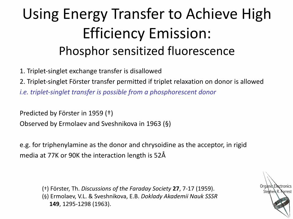
1. Triplet-singlet exchange transfer is disallowed2. Triplet-singlet Förster transfer permitted if triplet relaxation on donor is allowedi.e. triplet-singlet transfer is possible from a phosphorescent donor
Predicted by Förster in 1959 (†)Observed by Ermolaev and Sveshnikova in 1963 (§)
e.g. for triphenylamine as the donor and chrysoidine as the acceptor, in rigid media at 77K or 90K the interaction length is 52Å
(†) Förster, Th. Discussions of the Faraday Society 27, 7-17 (1959).(§) Ermolaev, V.L. & Sveshnikova, E.B. Doklady Akademii Nauk SSSR
149, 1295-1298 (1963).
Using Energy Transfer to Achieve High Efficiency Emission:
Phosphor sensitized fluorescence

Organic ElectronicsStephen R. Forrest
Phosphor sensitized fluorescenceMechanisms in guest-host systems
S
T
S
T
ISC S
T
exciton formation
phosphorescentsensitizer
fluorescentdye
host
exciton formation exciton formation
Phosphorescent donor and fluorescent acceptor must be separatedto prevent direct Dexter transfer to fluorescent triplet state Transfer possible for radiative triplet states
Baldo, M. A., Thompson, M. E. & Forrest, S. R. 2000. Nature, 403, 750.

Organic ElectronicsStephen R. Forrest
Delayed DCM2 fluorescence confirms sensitizing action of Ir(ppy)3
Red DCM2 Fluorophore sensitized by co-doping with green Ir(ppy)3 phosphor in an OLED
0 100 200 300 400 500 600 700 800 900 1000
1
10
100
Inte
nsity
(arb
itrar
y un
its)
Time (ns)
DCM2
Ir(ppy)3
Examine transient response of different spectral components of OLED luminescence.
Natural lifetime of DCM2 only ~ 1ns.
0.01 0.1 1 10 1003
4
5
6
7
89
10
Ext
erna
l qua
ntum
effi
cien
cy (%
)
Current density (mA/cm2)
0.00.10.20.30.40.50.60.70.80.91.0
EL
Inte
nsity
(arb
itrar
y un
its)
Wavelength (nm)400 450 500 550 600 650 700 750 800
0.2% DCM2and 8% Ir(ppy)3 in CBP
DCM2 fluorescence sensitized by Ir(ppy)3
DCM2
Ir(ppy)3
Roll-off in efficiency is due to chargetrapping on DCM2 molecules
Nearly complete energy transfer from Ir(ppy)3 to DCM2

Organic ElectronicsStephen R. Forrest
5
The Far Field: Radiative (Trivial) Energy Transfer
Donor Acceptor
!ω
• Involves the isotropic emission of a photon by a donor followed by absorption from a distant acceptor
• RDA>50 Å such that FRET inactive• No spin selection rules• Two step process:
• There is an orientation dependence due to dipole coupling
D* → D0 + !ω
A0 + !ω → A*
kET =9κ rad
2 ΦD
8πnrτ DRDA2 fD ω( )σ A ω( )exp −σ A ω( )ρNARDA( )dω∫
α A ω( ) = NAρMAσ A ω( ) /MwA =σ A ω( )ρNA
κ rad2 = cosθDA − cosθD cosθA( )2 : Geometric factor (dipoles couple when aligned)
: Absorption coefficient

Organic ElectronicsStephen R. Forrest
6
Summarizing our discussion on energy transferThe total rate is equal to the sum of the individual rates:
kET ,tot = kET ,exch + kET ,FRET + kET ,rad
Table 3.5: Energy transfer processes and their properties
Process Transfer rate
Distance Dependence Zone Characteristic transfer distance
Exchange (Dexter)
kET,exch
Contact <1 nm
FRET kET,FRET
Near <10 nm
Radiative kET,rad
Far >100 nm
Contact zone(Exchange: Dexter)
Near field zone(FRET: Förster)
Intermediate zone
Far field zone(Radiative: 1/r)
≤1≤10
>100

Organic ElectronicsStephen R. Forrest
7
Exciton Diffusion• The macroscopic transfer of energy resulting from a series of exciton
transfers between molecules• Process is random• Duration of process determined by lifetime τD of the exciton• Mean distance travelled known as diffusion length, LD
• Diffusion constant: LD2 = Dτ D
A"B"C"
D"
Donor-Acceptor Transfer
Non-radiative Radiative
PercolationCondition
High energy gap host (no transfer from guest)
Low energy gap guest

Organic ElectronicsStephen R. Forrest
8
Capture of excitons by acceptors
kc ≈ 4πDRc
Diffusion over large distances occurs by a series of random transfer steps from donor to acceptor⇒Relationship between capture rate, kc , and the diffusion constant is obtained using the diffusion equation⇒Assume probability for capture is unity when the exciton arrives within a distance Rc from the acceptor. (Rc = exciton capture radius.)
If diffusion occurs by individual FRET steps, then the relationship between LD andthe Förster radius is:
LD,FRET =16R03
a2
• Assumes molecules on a 3D cubic lattice, lattice constant a.• Analogous relationship holds for Dexter transfer
Chandrasekhar, S. 1943. Rev. Modern Phys., 15, 1.

Organic ElectronicsStephen R. Forrest
9
Diffusion Equation
D∇2n r,λ,t( )− n r,λ,t( )τ D
+G(r,λ,t) = ∂n r,λ,t( )∂t
n = exciton densityτD = exciton natural lifetimeG = Generation rate
Fick’s Law: In steady state, the flux is given by:
That is, flux is driven by a gradient in the concentration of n.
But energy conservation (no losses or sources) gives:
Which leads to Fick’s 2nd Law and the diffusion equation:
Diffusion from point of origin
Loss due to recombination
Generation due to incident light, etc.
J = −D∇n
∇J = − ∂n∂t
D∇2n = ∂n∂t
All variables functions of position,wavelength and time

Organic ElectronicsStephen R. Forrest
10
Measuring Exciton DiffusionBoundary Conditions and Solutions
Set up two experiments: one with a blocking and the other with a quenching layer on the material under test
Blocking: ∂n∂x
= 0
Blocking layer
x
Ener
gy �
o
Quenching: n=0
Quenching layer
x
Ener
gy
�
o
�
oG(x,λ,t) = I0 (λ,t)exp −α λ( )x⎡⎣ ⎤⎦
Spectrally resolved luminescent quenching (SR-PLQ)
Lunt, R. R., et al. J. Appl. Phys., 105, 053711.
Generation follows Beer-Lambert Law

Organic ElectronicsStephen R. Forrest
Diffusion Length Measurement by SR-PLQ
Lunt, R. R., et al. J. Appl. Phys., 105, 053711.
PL efficiency in the presence of a blocking (B) or quenching (Q) layer is a function of wavelength
Plot of their ratio gives a straight line with slope ∝ LD

Organic ElectronicsStephen R. Forrest
12
Measured Diffusion Lengths
Table 3.6: Measured diffusion lengths (LD) for singlet (S) and triplet (T) excitons of crystalline (C.) and amorphous (A.) films measured by spectrally resolved photoluminescence quenching.
Materiala,b Exciton Morphologyc Quenching/Blocking
Layerb LD (nm) D
(10-4cm2/s) NPD S A. C60/BCP 5.1 (±1.0) 0.7 (±0.2)
CBP S A. C60 (or NTCDA)/ Free
16.8 (±0.8) 40 (±12)
SubPc S A. C60/Bare 8.0 (±0.3) ≥6.4
PTCDA S C. - 55nm (flat) C60 (or NPD)/ NTCDA
10.4 (±1.0) 3.4 (±0.9)
DIP S C. - >150nm (up) C60/ Free 16.5 (±0.4) 15 (±4)
DIP S C. - 30nm (flat) C60/ Free 21.8 (±0.6) 26 (±7)
C60 S A. NPD/BPhen 34 (±3) 20 (±4)
C70 S A. NPD/BPhen 10 (±2)
PtOEP T - Mon. C. - >150nm (up) C60/BCP 18.0 (±0.6) 0.041
(±0.003)
PtOEP T – Dim. C. - >150nm (up) C60/BCP 13.1 (±0.5) 0.00061
(±0.0001) a All data are from (Lunt et al., 2009) except for C60 and C70 from (Bergemann et al., 2015). The larger error bars for LD for C60 and C70 is due to their comparatively weak luminescence.
b Materials used: NPD= N,N’-diphenyl-N,N’-bis(1-naphthyl)-1,1’biphenyl-4,4’’diamine; CBP=4’-bis(9-carbazolyl)-2,2’-biphenyl; PTCDA=3,4,9,10-perylenetetracarboxylic dianhydride; NTCDA=3,4,7,8 naphthalenetetracarboxylic dianhydride; SubPc= boron subphthalyocyanine chloride; DIP= diindenoperylene; PtOEP=Pt octaethylporphorin; BCP=bathocuproine; BPhen=bathophenanthroline; Free=no layer. c Up/flat refers to whether the molecular plane is perpendicular/parallel to the substrate.
Lunt, R. R., et al. J. Appl. Phys., 105, 053711.

Organic ElectronicsStephen R. Forrest
13
Diffusion Length Increases with Order
!!!!!
!!
Σ(Mean Xstal diameter)
Lunt, R. R., et al.. 2010. Adv. Mater., 22, 1233.
Why does the crystallite grain size have to be ~10・LD to realize the full LD of the material?
PTCDA grain size varied by OVPD growth conditions

Organic ElectronicsStephen R. Forrest
14
Annihilation!When excitons collide at a single molecular site, they can combine to form a single exciton and a ground state molecule: Exciton-exciton annihilation
Spin multiplicity can determine annihilation efficiency (Dexter vs FRET).Annihilation leads to losses, and phenomena like delayed fluorescence.
When excitons collide with charges, the charge can be excited, losing the exciton: Exciton-polaron annihilation

Organic ElectronicsStephen R. Forrest
15
Bad things happen to good excitons
Delayed fluorescenceTriplet fusion
S→ 2TSinglet fission whenES ≥ 2ET

Organic ElectronicsStephen R. Forrest
16
Rate Equations for Annihilation
dSdt
= GS − kS S − 12
kSSAS 2 − kSTAST − kSPASP + kTTA−ST2
dTdt
= GT − kTT − 2kTTA−ST2 − 1
2kTTA−TT 2 − kTPATP
Including all processes, we get two coupled rate equations:
Exciton generation rates
Example: Exciton generation by current (J) injection:
GT ,S (J ) = χT ,SηJ j / qd
Probability for forming triplet or singlet: χT =¾; χS =¼ (spin formation statistics)
electron-to-exciton conversion ratio
Layer thickness
But j is due to the injection of polarons, introducing rate equation #3:
dPdt
=j t( )qd
− krecP2

Organic ElectronicsStephen R. Forrest
17
Langevin recombination
krec =
qε rε0
µh + µe( )
Random polaron collisions: Pe + Ph → !Ω (heat, or possibly S or T)
Langevin recombination rate:
dTdt
= 34krecP
2 − kTT − 54kTTAT
2 − kTPATP
Giving two new rate equations:
dSdt
= 14krecP
2 − kSS +14kTTAT
2 − kSTAST
kS=1x10⁹(s*1 (( (kTPA=2x10*13(cm3*(s*1(kT=0(s*1 (( (( (kTSA=2x10*10(cm3*(s*1(kTTA=0(cm3*(s*1 ((µ=1x10*5(cm2*V*1s*1(
The fractions come from spin statistics:Ex.
54kTTAT
2 ⇒ T1 +T2kTTA⎯ →⎯ T12 ⊕ T3 +T4( ) kTTA⎯ →⎯ T12 +T34
kTTA⎯ →⎯ T5
Bimolecular process when an electron and hole collide
Transient response in a material with triplets, singlets & polarons
Zhang et al., Chem. Phys. Lett., 495, 161 (2010)

Organic ElectronicsStephen R. Forrest
18
DCM2:Alq3 Fluorescent OLEDsLuminance)(arb.))
Luminescence))
Turn –on transient
Accumulation of triplets due to injection leading to STA
Turn –off transient
Delayed fluorescence due to TTA
Zhang et al., Chem. Phys. Lett., 495, 161 (2010)
Fits to rate equations shown by lines
Organic ElectronicsStephen R. Forrest
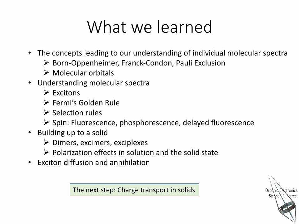
What we learned• The concepts leading to our understanding of individual molecular spectra
Ø Born-Oppenheimer, Franck-Condon, Pauli ExclusionØ Molecular orbitals
• Understanding molecular spectraØ ExcitonsØ Fermi’s Golden RuleØ Selection rulesØ Spin: Fluorescence, phosphorescence, delayed fluorescence
• Building up to a solidØ Dimers, excimers, exciplexesØ Polarization effects in solution and the solid state
• Exciton diffusion and annihilation
The next step: Charge transport in solids
Organic ElectronicsStephen R. Forrest
Electronic Properties of Organic Semiconductors
Electronic Properties 1
Energy Bands
Chapter 4.1

Organic ElectronicsStephen R. Forrest
21
Organic & Inorganic Semiconductor Properties: A Reminder
21
Property Organics Inorganics
Bonding van der Waals Covalent/Ionic
Charge Transport Polaron Hopping Band Transport
Mobility <0.1 cm2/V·s ~1000 cm2/V·s
Absorption 105-106 cm-1 104-105 cm-1
Excitons Frenkel Wannier-Mott
Binding Energy ~500-800 meV ~10-100 meV
Exciton Radius ~10 Å ~100 Å
Organic ElectronicsStephen R. Forrest
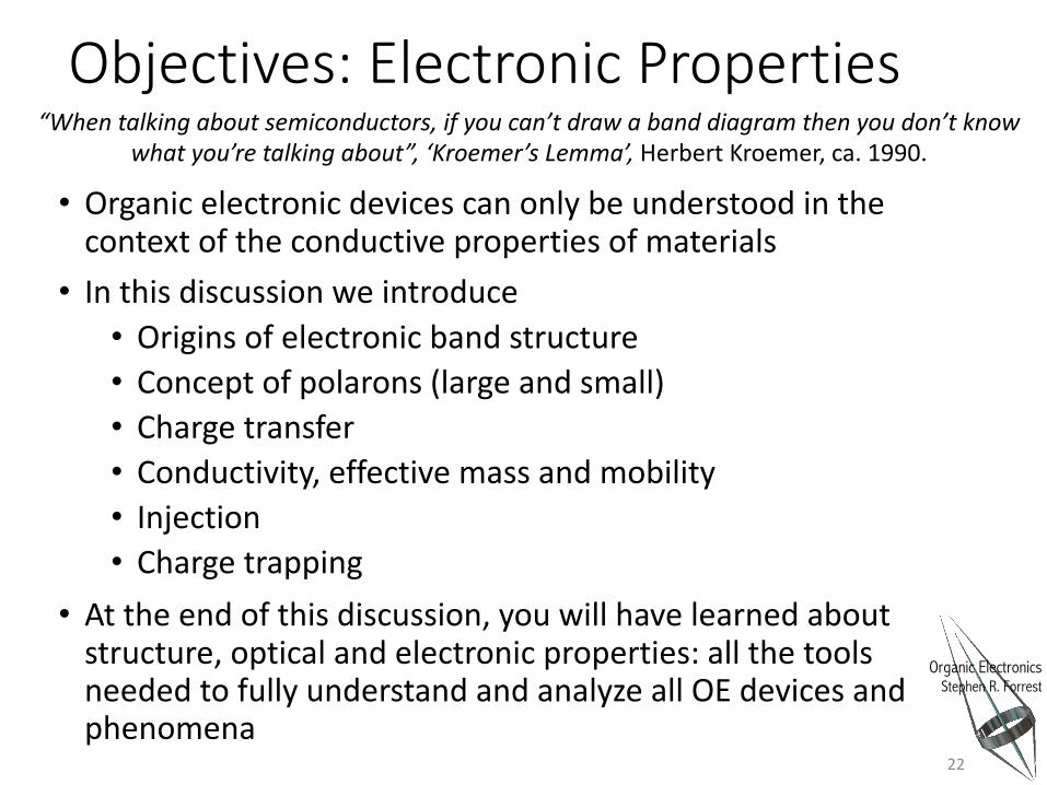
Objectives: Electronic Properties
• Organic electronic devices can only be understood in the context of the conductive properties of materials• In this discussion we introduce
• Origins of electronic band structure• Concept of polarons (large and small)• Charge transfer• Conductivity, effective mass and mobility• Injection• Charge trapping
• At the end of this discussion, you will have learned about structure, optical and electronic properties: all the tools needed to fully understand and analyze all OE devices and phenomena
22
“When talking about semiconductors, if you can’t draw a band diagram then you don’t know what you’re talking about”, ‘Kroemer’s Lemma’, Herbert Kroemer, ca. 1990.

Organic ElectronicsStephen R. Forrest
From energy levels to energy bands
Eg#
BW# Conduc,on##Band#
Valence#Band#
DOS#
Energy#
(a)#
Eg#HOMO#
Energy#
HOMO:1#HOMO:2#
• ##• ##• ##• ##
• ##• ##• ##• ##
• ##• ##• ##• ##
LUMO+2#LUMO+1#LUMO#
• ##• ##• ##• ##
(b)#
DOS#
Due to limited orbital overlap between adjacent molecules, energy bandwidths are small:• Large effective mass• Low charge velocity (and hence mobility)• Low conductivity• Band conduction is replaced by charge hopping
23

Organic ElectronicsStephen R. Forrest
Modes of Conduction
24
(a) ECBM
(b) (c)
ELUMO
EEAEIP
EVAC
(a) ECBM
(b) (c)
ELUMO
EEAEIP
EVAC
Band transport
Hopping and tunneling transport
• Coherent• Charge mean free path λ>>a•
BW
BW > kBT , !ω 0
Molecule
• Incoherent (each step independent of previous)• Charge mean free path λ~a• Tunneling between states of equal energy is band-like• BW < kBT , !ω 0
EB

Organic ElectronicsStephen R. Forrest
Hopping
25
Time
When there is strong electron-phonon (small polaron) coupling, we get another condition for band transport:
µ > qa
2
!!ω 0
kBT⎛⎝⎜
⎞⎠⎟
Optical phonon energy(typ. ~ 100 meV)
µ ~ 20 cm2/V-s at room temperature…very high (and probably unrealistic)!
Organic ElectronicsStephen R. Forrest
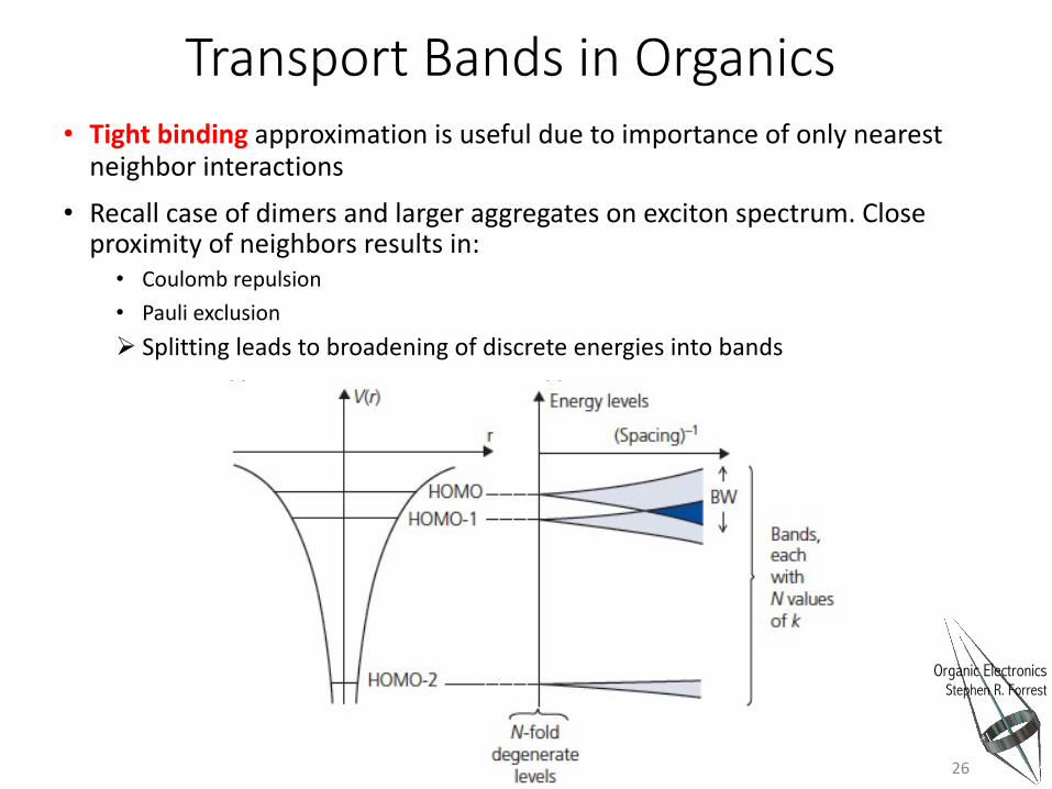
Transport Bands in Organics• Tight binding approximation is useful due to importance of only nearest
neighbor interactions
• Recall case of dimers and larger aggregates on exciton spectrum. Close proximity of neighbors results in:
• Coulomb repulsion• Pauli exclusionØ Splitting leads to broadening of discrete energies into bands
26

Organic ElectronicsStephen R. Forrest
Tight Binding ApproximationCalculating organic band structure
• Start with the unperturbed molecular orbitals of HOMO, HOMO-1, HOMO-2…, and LUMO, LUMO+1… These will diverge into separate bands as molecules approach
• The total Hamiltonian consists of the individual molecular component and the interaction between neighbors:
• Hint = U(r) that must be consistent with Bloch’s Theorem:• R = lattice spacing
• From LCAO, for the nth orbital, over N lattice sites, for wavevector k:
• This must have translational invariance of(Bloch Theorm)
27
Htot = Hmol + H int
U(r +R) =U(r)
ψ nk r( ) = ckii
N
∑ ψ n r −Ri( )
Contribution from ith molecule
ψ k r +R( ) = eikiRψ k r( ) cki =
1NeikiR

Organic ElectronicsStephen R. Forrest
Tight Binding Approximation-cont’d
• Schrodinger’s Eq. is now:
• It follows that:
• Solving, and since the eigenvalues of Hmol are Em of the original molecules:
Since
And solving this for an s-like HOMO level this equation has solution:
(higher symmetry orbitals have multiple solutions but we’ll keep it simple!)
28
Htotψ k r( ) = Hmol + H int( )ψ k r( ) = E k( )ψ k r( )
ψ m r( ) Htot ψ k r( ) = ψ m r( ) Hmol + H int( )ψ k r( ) = E k( ) ψ m r( )ψ k r( )Starting orbital wavefunction
E k( )− Em( ) ψ m r( )ψ k r( ) = ψ m r( ) H int ψ k r( )
ψ k r +R( ) = eikiRψ k r( )
E k( )− EHOMO = − E k( )− EHOMO( ) α Ri( )
i
N
∑ eikiRi − β − J Ri( )i
N
∑ eikiRi : overlap
Organic ElectronicsStephen R. Forrest
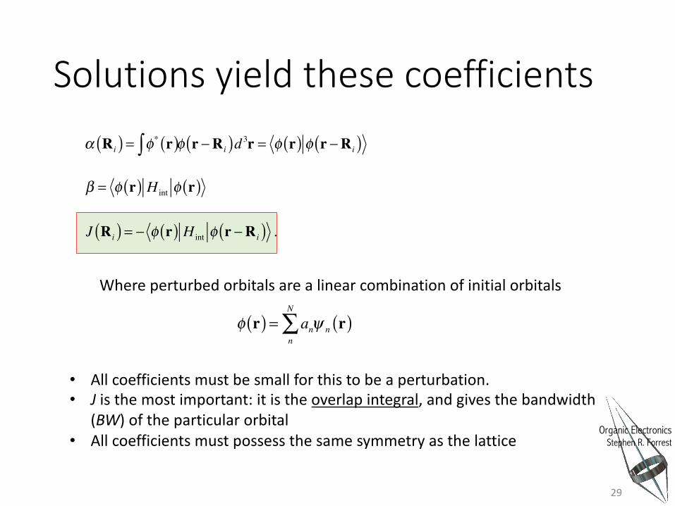
Solutions yield these coefficients
29
α Ri( ) = φ* r( )∫ φ r −Ri( )d 3r = φ r( ) φ r −Ri( )
β = φ r( ) H int φ r( )
J Ri( ) = − φ r( ) H int φ r −Ri( ) .
• All coefficients must be small for this to be a perturbation.• J is the most important: it is the overlap integral, and gives the bandwidth
(BW) of the particular orbital• All coefficients must possess the same symmetry as the lattice
φ r( ) = ann
N
∑ ψ n r( )
Where perturbed orbitals are a linear combination of initial orbitals

Organic ElectronicsStephen R. Forrest
• Now all the coefficients are small (this is only a perturbation), so the simple solution to E(k) is just:
• And the overlap between the perturbed and initial wavefunctions
• To solve this, we actually need a potential U(R) that should be large when the overlap is small, and small when the overlap is big so as not to perturb the system too much.
30
Tight Binding Approximation-cont’d.
E k( ) ~ Δ ′E + 2EW cos k iR( )Sum of EHOMO & excited monomer energies
BW = 4EW
BW ~ ψ m r( ) H int ψ k r −Rn.n.( ) ,
U(r) = −U0sin2 πR / a( )πR / a( )2 -U
/U0
-4 -3 -2 -1 1 2 3 4
1.0
0.9
0.8
0.7
0.6
0.5
0.4
0.3
0.2
0.1
0πR/a

Organic ElectronicsStephen R. Forrest
Simple Example of the TBA: fcc lattice
• First, assume α<<1 ⇒ in absence of interaction, overlap very small
• Now in fcc lattice, molecules at all 12 positions at ½a from origin• J has form:
• Total solution is cosine-like with BW=8Jfcc:
• Near zone center, ½ka is small.
31
E k( )− EHOMO = −β − J Ri( )
i=1
12
∑ cos k iRi( )
J Ri( ) = J fcc ~ − φ r( ) H int r( ) φ x − a2, y − a
2, z⎛
⎝⎜⎞⎠⎟
E k( )− EHOMO = −β − 4J fcc {cos 12 kxa( )cos 1
2 kya( ) + cos 12 kxa( )cos 1
2 kza( ) + cos 1
2 kya( )cos 12 kza( )}
vx (k) =
2J fcckxa2
! mx* = !2
2J fcca2
From energy dispersion relation, we obtian group velocity and mass
(same along y, z in cubic lattice)
Organic ElectronicsStephen R. Forrest
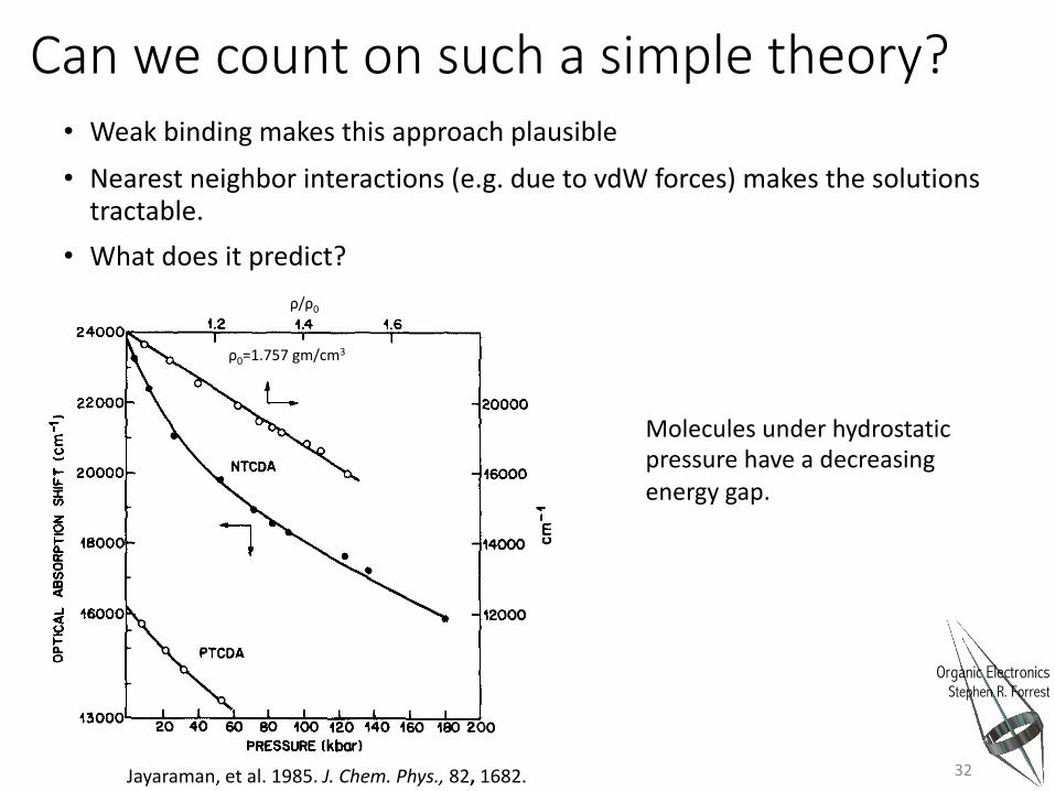
Can we count on such a simple theory?• Weak binding makes this approach plausible
• Nearest neighbor interactions (e.g. due to vdW forces) makes the solutions tractable.
• What does it predict?
32
ρ0=1.757gm/cm3
ρ/ρ0
Molecules under hydrostatic pressure have a decreasing energy gap.
Jayaraman, et al. 1985. J. Chem. Phys., 82, 1682.