Vol. 2000 Ruled Surface Machining on Five-Axis CNC · PDF fileJournal of Manufachlrzng...
11
Journal of Manufachlrzng Processes Vol. 2mo. 1 2000 0 Ruled Surface Machining on Five-Axis CNC Machine Tools Rong-Shine Lin, Dept. of Mechanical Engineering, National Chung Cheng University, Chia-Yi, Taiwan Yoram Koren, Dept. of Mechanical Engineering and Applied Mechanics, The University of Michigan, Ann Arbor, Michigan Abstract To achieve high precision and high productivity in machin- ing sculptured surfaces, a new architecture for a five-axis CNC interpolator for machining ruled surfaces was devel- oped and demonstrated on a milling machine. The objective of the five-axis interpolator is to continuously maintain the milling cutter axis in parallel with the straight lines of the ruled surface. The cutter position and orientation are calculated at each sampling period of the interpolator, and corresponding axial position commands are generated by an inverse kine- matics algorithm. This real-time approach produces precise surfaces and requires substantially less machining time com- pared to the conventional off-line approach. Two new g- codes are also given in this paper for the new interpolator to produce part surfaces in CNC milling machines. Keywords: Five-Axis Machining, Five-Axis CNC, Ruled Surface, Computer Control Introduction Parts containing ruled surfaces, such as conic and cylindrical surfaces, can be machined either by ball- end cutters on three-axis milling machines or by flank milling on five-axis milling machines. Using flank milling enables a tremendous increase in pro- ductivity as well as improvement of the surface fin- ish; however, the conventional methods for five-axis machining utilize the off-line approach by which the CAD system divides the curve into a set of line segments that approximates the curve at the desired tolerance.'-' These line segments are further processed by post processors to produce the g-code that contains the computer numeric control (CNC) commands needed to control the machine. The g- code is fed into the CNC real-time interpolator whose major function is to generate coordinated reference inputs for the servocontrollers that control the machine tool axes. Conventional off-line approaches for five-axis machines typically assume a constant tool orienta- tion along each segment. The constant orientation algorithm causes severe roughness around the end- points along the surface because the orientation changes are abrupt at these points. More advanced approaches assume a linear change in the tool orien- tation between each successive end-point. The linear orientation algorithm produces a better surface but still interpolates the orientations inaccurately between end-points (because the change of orienta- tion is not necessarily linear), which causes surface errors. An additional drawback of off-line methods is that the cutter accelerates and decelerates at each segment, which increases surface nonuniformity and substantially increases cutting time.8.9 Chou and Yanglo provided a mathematical formulation for a Euler-angle-type five-axis machine to track a para- metric curve. Their work interpolated the curve cor- rectly, but the required tool orientations were assumed to be given from CAD files that did not fit real-time implementations for CNC systems. To overcome these drawbacks, this paper devel- ops an algorithm for a real-time five-axis interpola- tor that continuously controls tool orientation and position. This interpolator can perform accurate pro- duction of ruled surfaces with flank cutters. The interpolator, which is contained in the CNC comput- er, calculates new commands in the same time peri- od used for sampling the control loop feedback (typ- ically 0.5 ms to 5 ms). In each sampling period, the interpolator performs two steps: (I) trajectory plan- ning based on a constant feed rate and (2) inverse kinematics transformation based on the structure of the machine. The developed real-time interpolator for machin- ing ruled surfaces is shown in Figure 1. The input to the interpolator is the NC g-code, which contains the geometric information of the part surface as well as the cutting conditions, such as feed rate, spindle speed, specific tool type, and so on. The trajectory planning portion generates the tool position (X, X Z) and orientation (Ox, O,, 0,) of the cutter in each sampling period based on the surface geometry and
Transcript of Vol. 2000 Ruled Surface Machining on Five-Axis CNC · PDF fileJournal of Manufachlrzng...

Journal of Manufachlrzng Processes Vol. 2mo. 1
2000 0 Ruled Surface Machining on Five-Axis CNC Machine Tools Rong-Shine Lin, Dept. of Mechanical Engineering, National Chung Cheng University, Chia-Yi, Taiwan Yoram Koren, Dept. of Mechanical Engineering and Applied Mechanics, The University of Michigan, Ann Arbor, Michigan
Abstract To achieve high precision and high productivity in machin-
ing sculptured surfaces, a new architecture for a five-axis CNC interpolator for machining ruled surfaces was devel- oped and demonstrated on a milling machine. The objective of the five-axis interpolator is to continuously maintain the milling cutter axis in parallel with the straight lines of the ruled surface. The cutter position and orientation are calculated at each sampling period of the interpolator, and corresponding axial position commands are generated by an inverse kine- matics algorithm. This real-time approach produces precise surfaces and requires substantially less machining time com- pared to the conventional off-line approach. Two new g- codes are also given in this paper for the new interpolator to produce part surfaces in CNC milling machines.
Keywords: Five-Axis Machining, Five-Axis CNC, Ruled Surface, Computer Control
Introduction Parts containing ruled surfaces, such as conic and
cylindrical surfaces, can be machined either by ball- end cutters on three-axis milling machines or by flank milling on five-axis milling machines. Using flank milling enables a tremendous increase in pro- ductivity as well as improvement of the surface fin- ish; however, the conventional methods for five-axis machining utilize the off-line approach by which the CAD system divides the curve into a set of line segments that approximates the curve at the desired tolerance.'-' These line segments are further processed by post processors to produce the g-code that contains the computer numeric control (CNC) commands needed to control the machine. The g- code is fed into the CNC real-time interpolator whose major function is to generate coordinated reference inputs for the servocontrollers that control the machine tool axes.
Conventional off-line approaches for five-axis machines typically assume a constant tool orienta- tion along each segment. The constant orientation algorithm causes severe roughness around the end-
points along the surface because the orientation changes are abrupt at these points. More advanced approaches assume a linear change in the tool orien- tation between each successive end-point. The linear orientation algorithm produces a better surface but still interpolates the orientations inaccurately between end-points (because the change of orienta- tion is not necessarily linear), which causes surface errors. An additional drawback of off-line methods is that the cutter accelerates and decelerates at each segment, which increases surface nonuniformity and substantially increases cutting time.8.9 Chou and Yanglo provided a mathematical formulation for a Euler-angle-type five-axis machine to track a para- metric curve. Their work interpolated the curve cor- rectly, but the required tool orientations were assumed to be given from CAD files that did not fit real-time implementations for CNC systems.
To overcome these drawbacks, this paper devel- ops an algorithm for a real-time five-axis interpola- tor that continuously controls tool orientation and position. This interpolator can perform accurate pro- duction of ruled surfaces with flank cutters. The interpolator, which is contained in the CNC comput- er, calculates new commands in the same time peri- od used for sampling the control loop feedback (typ- ically 0.5 ms to 5 ms). In each sampling period, the interpolator performs two steps: (I) trajectory plan- ning based on a constant feed rate and (2) inverse kinematics transformation based on the structure of the machine.
The developed real-time interpolator for machin- ing ruled surfaces is shown in Figure 1. The input to the interpolator is the NC g-code, which contains the geometric information of the part surface as well as the cutting conditions, such as feed rate, spindle speed, specific tool type, and so on. The trajectory planning portion generates the tool position (X, X Z) and orientation (Ox, O,, 0,) of the cutter in each sampling period based on the surface geometry and

.Journal of Munujactiiring Processes Vol. 21No. I 2000
Figure I Proposed Real-Time Interpolator for Machining Ruled Surfaces
Figure 2 Example of the Ruled Surface and Its Flank Milling
specified feed rate. This is a generic, machine-inde- pendent algorithm. Based on the calculated cutter's position and orientation, the reference values (x, JI, z, a, b) of the five axes are computed by the inverse kinematics transformation, an algorithm that depends on the structure of each particular machine. The detailed operation of these two algorithms is described in the following two sections. Examples are given in a later section.
Trajectory Planning The trajectory planning algorithm generates the
locations and orientations for the cutting tools based on part geometry and feed rate, which are obtained from the part program. The special geometric prop- erties of ruled surfaces are described in this section. Based on these properties, algorithms are presented
to calculate tool positions and tool orientations pre- cisely along the ruled surface with machining at a constant feed rate.
Ruled Surfaces A ruled surface is defined as a surface that
through each point of it passes at least one straight line lying entirely on the surface." In other words, a ruled surface is a surface generated by a family of straight lines (for example, a conic surface). This special geometric property can be used to increase the productivity of machining ruled surfaces on five-axis machines. The basic idea of this type of machining is moving the cutter's edge to follow the straight lines of the ruled surface. A ruled surface can be expressed by the following equation:
S(u, v) = (1 - v) C,, (u) + v C, (u) (1)
where Co and C1 are two boundary curves of the ruled surface, which are known as directrices; u and v are parameters, normally 0 5 u, v 5 1. An exam- ple of a ruled surface is shown in Figure 2.
Position Calculation In this research, the real-time five-axis interpola-
tor is proposed to be implemented on finish cutting, which removes only a small amount of material. Therefore, the tool motion can be assumed as con- stant feed rate machining. To simplify the imple- mentation process, the lower boundary curve of the ruled surface is chosen for the tool contact trajecto- ry, C(u), as follows:
where
The interpolator calculates the tool position at each sampling period (AT) based on this parametric curve. However, the constant change in the parame- ter Au in the parametric domain does not guarantee the constant length in the Cartesian domain, and consequently does not guarantee a constant feed

Journal of Manufacturing Processes Vol. 21No. 1
2000
rate. To obtain the constant feed rate ( V ) , the con- version between the parameter u and the constant distance that the tool moves at each sampling peri- od has to be derived. A solution based on Taylor's expansion is used to obtain the value of Au that cor- responds to the equal trajectory length of the para- metric curve. Eq. (3) below shows the function of u in terms of the length (V -AT) that the tool moves during one sampling period. If the machining feed rate V is constant, ( V . AT) is constant as well.
where
dx dv , dz x'=-,y'=-, a n d z =- du du du
The subscripts k and k-1 mean the current sampling time and previous sampling time, respectively. The cutter contact location at the kth sampling period can be obtained by substituting uk, from Eq. (3), into Eq. (2), as follows:
The precision of this approach has been ana- lyzed in Shpitalni, Koren, and Lo.12 It has been shown that the reference positions calculated by this real-time interpolator algorithm result in very small contour errors compared with conventional off-line interpolators. The variations in the veloci- ty commands (feed rates in g-codes) by the real- time approach are negligible for most applications. By contrast, the off-line approach causes very large velocity errors.
In addition, in machining by the conventional off- line interpolator, the machine has to follow a sequence of short straight lines, which causes accel- eration and deceleration at the beginning and the ending of each line. This results in a substantial increase in machining time. In contrast, the real-time approach reads the g-code of the parametric curve directly and generates the reference positions for the tool at the same rate needed by the control loops. This eliminates the acceleration and deceleration
effect and consequently results in a substantial reduction in machining time.8
To obtain the cutter's location, the cutter contact location, Eq. (4), must be offset a distance of the cut- ter radius along the surface normal direction. Therefore, the tool center position at the kth Sam- pling can be calculated as follow^:'^^^^
where r is the cutter radius and S is the ruled surface.
Orientation Calculation The key idea of using five-axis machining for
ruled surfaces is controlling the milling cutter axis in parallel with the straight lines of the ruled surface. In other words, the cutter not only follows the boundary curve of the ruled surface but also orients the cutter axis in the direction of the straight line where the cutter is located. Elaborated first is the off-line approach that varies cutter orientations lin- early between the intermediate points of the curve approximated by linear segments. With this off-line approach, the interpolated orientation n between the intermediate points is as follows:
where nk and nk-l are the orientations of the two end- points of the approximated segment and correspond to the parameters uk and ukl, respectively. This approach interpolates inaccurate orientations because the changes in the tool orientations are not necessarily linear. The orientation errors subse- quently affect the position accuracy (discussed fur- ther in the section below on inverse kinematics transformation). As an example, the orientation errors caused by the off-line interpolation of a ruled surface in terms of the parametric form
S(u, v) = (1 - v) co (u) + v C1 (u), 0 5 u , v 5 1
x(u) = 2.205u3 - 7.425u2 + 0 .22~ + 5
y(u) = -2.205u3 - 0.8 1u2 + 8.05 1
z(u) = 20 (continued)
Journal of Manufacturing Processes Vol. 21No. 1 2000
Errors (degree)
0.01 5
0.0125
0.01
0 0075
0.005
0 0025
0.2 0 4 0 6 0.8 1
Parameter (u)
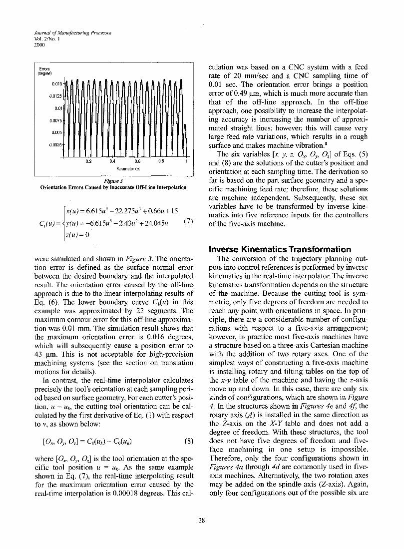
Figure 3 Orientation Errors Caused by Inaccurate Off-Line Interpolation
were simulated and shown in Figure 3. The orienta- tion error is defined as the surface normal error between the desired boundary and the interpolated result. The orientation error caused by the off-line approach is due to thehear interpolating results of Eq. (6). The lower boundary curve Cl(u) in this example was approximated by 22 segments. The maximum contour error for this off-line approxima- tion was 0.01 rnrn. The simulation result shows that the maximum orientation error is 0.016 degrees, which will subsequently cause a position error to 43 pm. This is not acceptable for high-precision machining systems (see the section on translation motions for details).
In contrast, the real-time interpolator calculates precisely the tool's orientation at each sampling peri- od based on surface geometry. For each cutter's posi- tion, u = uk, the cutting tool orientation can be cal- culated by the first derivative of Eq. (I) with respect to v, as shown below:
where [Ox, O,, O,] is the tool orientation at the spe- cific tool position u = uk. As the same example shown in Eq. (7), the real-time interpolating result for the maximum orientation error caused by the real-time interpolation is 0.00018 degrees. This cal-
culation was based on a CNC system with a feed rate of 20 mmlsec and a CNC sampling time of 0.01 sec. The orientation error brings a position error of 0.49 pm, which is much more accurate than that of the off-line approach. In the off-line approach, one possibility to increase the interpolat- ing accuracy is increasing the number of approxi- mated straight lines; however, this will cause very large feed rate variations, which results in a rough surface and makes machine ~ibrat ion.~
The six variables [x, y, z, Ox, O,, O,] of Eqs. (5) and (8) are the solutions of the cutter's position and orientation at each sampling time. The derivation so far is based on the part surface geometry and a spe- cific machining feed rate; therefore, these solutions are machine independent. Subsequently, these six variables have to be transformed by inverse kine- matics into five reference inputs for the controllers of the five-axis machine.
Inverse Kinematics Transformation The conversion of the trajectory planning out-
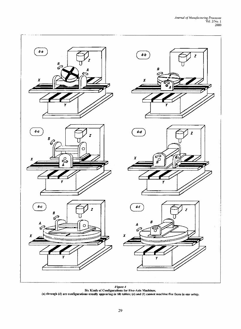
puts into control references is performed by inverse kinematics in the real-time interpolator. The inverse kinematics transformation depends on the structure of the machine. Because the cutting tool is sym- metric, only five degrees of freedom are needed to reach any point with orientations in space. In prin- ciple, there are a considerable number of configu- rations with respect to a five-axis arrangement; however, in practice most five-axis machines have a structure based on a three-axis Cartesian machine with the addition of two rotary axes. One of the simplest ways of constructing a five-axis machine is installing rotary and tilting tables on the top of the x-y table of the machine and having the z-axis move up and down. In this case, there are only six kinds of configurations, which are shown in Figure 4. In the structures shown in Figures 4e and 4J; the rotary axis (A) is installed in the same direction as the Z-axis on the X-Y table and does not add a degree of freedom. With these structures, the tool does not have five degrees of freedom and five- face machining in one setup is impossible. Therefore, only the four configurations shown in Figures 4a through 4d are commonly used in five- axis machines. Alternatively, the two rotation axes may be added on the spindle axis (Z-axis). Again, only four configurations out of the possible six are
Journal of Manufacturing Processes Vol. 2mo. 1
2000
Figure 4 Six Kinds of Configurations for Five-Axis Machines.
(a) through (d) are configurations usually appearing in tilt tables; (e) and (f) cannot machine five faces in one setup.
Journal of Munufacrurzng Proce~ses Vol 2INo. 1 2000
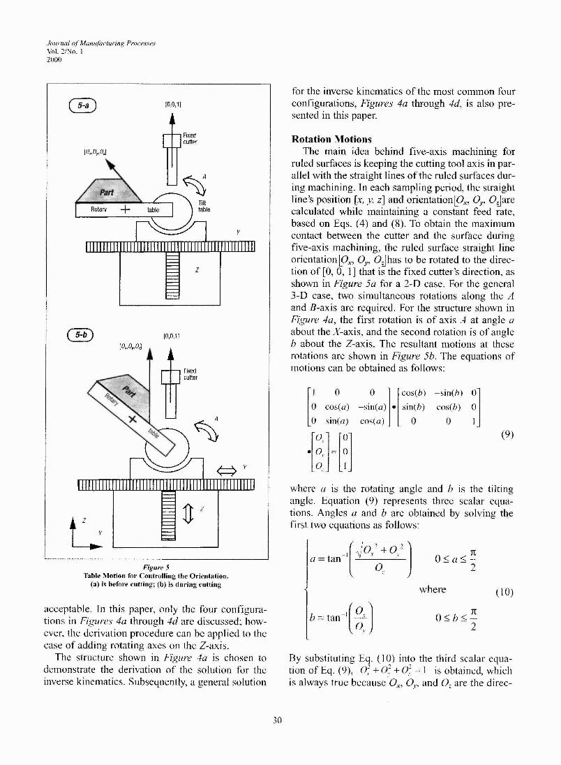
Figure 5 Table Motion for Controlling the Orientation.
(a) i s before cutting; (b) is during cutting
acceptable. In this paper, only the four configura- tions in Figures 4u through 4d are discussed; how- ever, the derivation procedure can be applied to the case of adding rotating axes on the Z-axis.
The structure shown in Figure 4u is chosen to demonstrate the derivation of the solution for the inverse kinematics. Subsequently, a general solution
for the inverse kinematics of the most common four configurations, Figures 4a through 4d, is also pre- sented in this paper.
Rotation Motions The main idea behind five-axis machining for
ruled surfaces is keeping the cutting tool axis in par- allel with the straight lines of the ruled surfaces dur- ing machining. In each sampling period, the straight line's position [x, y, z] and o r i en t a t i~np~ , O,, 0;lare calculated while maintaining a constant feed rate, based on Eqs. (4) and (8). To obtain the maximum contact between the cutter and the surface during five-axis machining, the ruled surface straight line orientationlo,, O,, OJhas to be rotated to the direc- tion of [0, 0 , 11 that is the fixed cutter's direction, as shown in Figure 5a for a 2-D case. For the general 3-D case, two simultaneous rotations along the A and B-axis are required. For the structure shown in Figure 4a, the first rotation is of axis A at angle a about the X-axis, and the second rotation is of angle b about the Z-axis. The resultant motions at these rotations are shown in Figure 56. The equations of motions can be obtained as follows:
where a is the rotating angle and b is the tilting angle. Equation (9) represents three scalar equa- tions. Angles a and b are obtained by solving the first two equations as follows:
where ( 1 0)
By substituting Eq. (10) into the third scalar equa- tion of Eq. (9), 0; + 0; + O_? = 1 is obtained, which is always true because Or, O,, and 0, are the direc-
Journal of Manufacturing Processes Val. 2iNo. 1
2000
tional cosines of a unit vector in Cartesian coordinates.
Translation Motions By the rotations demonstrated in Figures 5a and
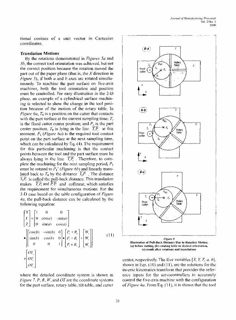
5b, the correct tool orientation was achieved, but not the correct position because the rotation moved the part out of the paper plane (that is, the X direction in Figure 5), if both a and b axes are rotated simuita- neously. To machine the part surface on five-axis machines, both the tool orientation and position must be controlled. For easy illustration in the 2-D plane, an example of a cylindrical surface machin- ing is selected to show the change in the tool posi- tion because of the motion of the rotary table. In Figure 6a, To is a position on the cutter that contacts with the part surface at the current sampling time; T, is the fixed cutter center position; and PC is the part center position. To is lying in the line at this moment. P, (Figure 6a) is the required tool contact point on the part surface at the next sampling time, which can be calculated by Eq. (4). The requirement for this particular machining is that the contact points between the tool and the part surface must be always lying in the line . Therefore, to com- plete the machining for the next sampling period, P, must be rotated to P,' (Figure 6b) and linearly trans- lated back to To by the distance . The distance T,4 is called the pull-back distance. This translation makes and and collinear, which satisfies the requirement for simultaneous motions. For the 3 -0 case based on the table configuration of Figure 4a, the pull-back distance can be calculated by the following equation:
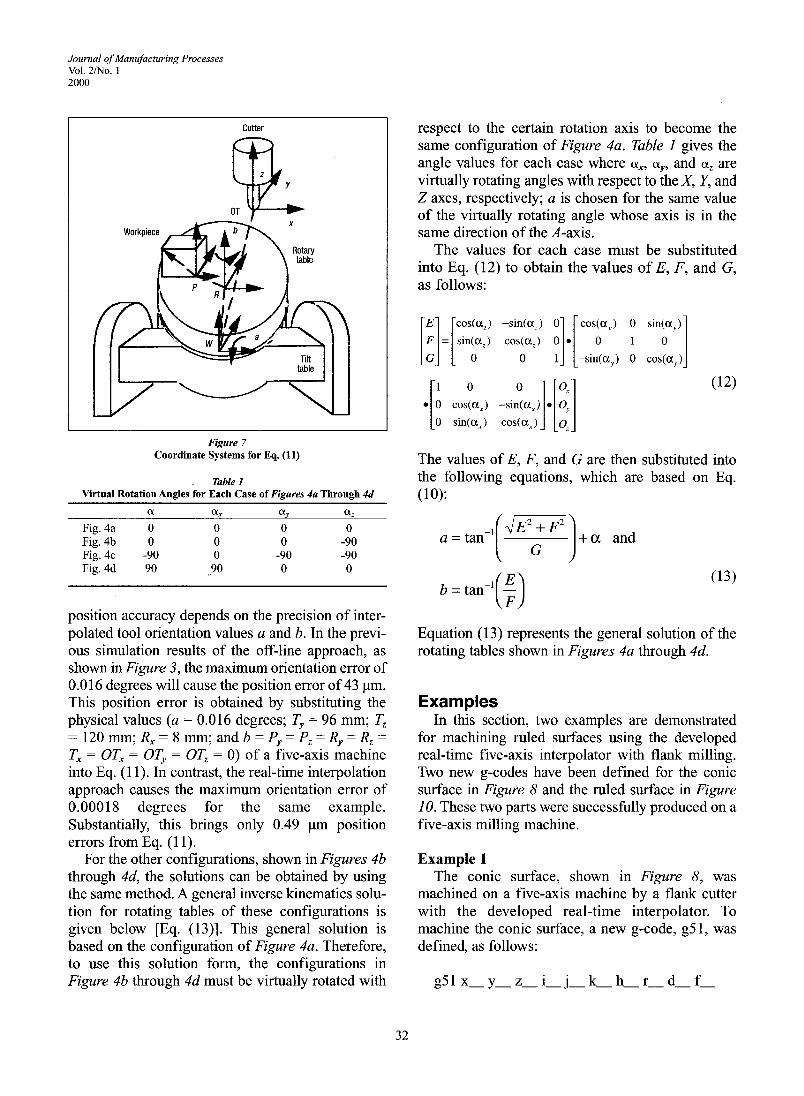
where the detailed coordinate system is shown in Figure 7. P, R, W, and OT are the coordinate systems for the part surface, rotary table, tilt table, and cutter
I I
Figure 6 lllustration of Pull-Back Distance Due to Rotation Motion. (a) before cutting, (b) rotating table to desired orientation,
(c) result after rotations and translations
center, respectively. The five variables [X, Z 2, a, b] , shown in Eqs. (10) and (1 I), are the solutions for the inverse kinematics transform that provides the refer- ence inputs for the servocontrollers to accurately control the five-axis machine with the configuration of Figure 4a. From Eq. (1 l), it is shown that the tool
Journal of Manufacturing Processes Vol. 2mo. 1 2000
Cutter
Figure 7 Coordinate Systems for Eq. (11)
Table 1 Virtual Rotation Angles for Each Case of Figures 4a Through 4d
0( cu, C'-Y a,
Fig. 4a 0 0 0 0 Fig. 4b 0 0 0 -90 Fig. 4c -90 0 -90 -90 Fig. 4d 90 90 0 0
position accuracy depends on the precision of inter- polated tool orientation values a and b. In the previ- ous simulation results of the off-line approach, as shown in Figure 3, the maximum orientation error of 0.016 degrees will cause the position error of 43 pm. This position error is obtained by substituting the physical values (a = 0.016 degrees; T, = 96 mm; T, = 120 mm; R, = 8 mm; and b = P, = P, = R, = R, =
T, = OT, = OT, = OT, = 0) of a five-axis machine into Eq. (1 I). In contrast, the real-time interpolation approach causes the maximum orientation error of 0.00018 degrees for the same example. Substantially, this brings only 0.49 pm position errors from Eq. (1 1).
For the other configurations, shown in Figures 4b through 4d, the solutions can be obtained by using the same method. A general inverse kinematics solu- tion for rotating tables of these configurations is given below [Eq. (13)l. This general solution is based on the configuration of Figure 4a. Therefore, to use this solution form, the configurations in Figure 4b through 4d must be virtually rotated with
respect to the certain rotation axis to become the same configuration of Figure 4a. Table 1 gives the angle values for each case where ol,, ol,, and a, are virtually rotating angles with respect to the X, Y, and Z axes, respectively; a is chosen for the same value of the virtually rotating angle whose axis is in the same direction of the A-axis.
The values for each case must be substituted into Eq. (12) to obtain the values of E, F, and G, as follows:
The values of E, F, and G are then substituted into the following equations, which are based on Eq. (10):
&TF ]+CX and
Equation (13) represents the general solution of the rotating tables shown in Figures 4a through 4d.
Examples In this section, two examples are demonstrated
for machining ruled surfaces using the developed real-time five-axis interpolator with flank milling. Two new g-codes have been defined for the conic surface in Figure 8 and the ruled surface in Figure 10. These two parts were successfully produced on a five-axis milling machine.
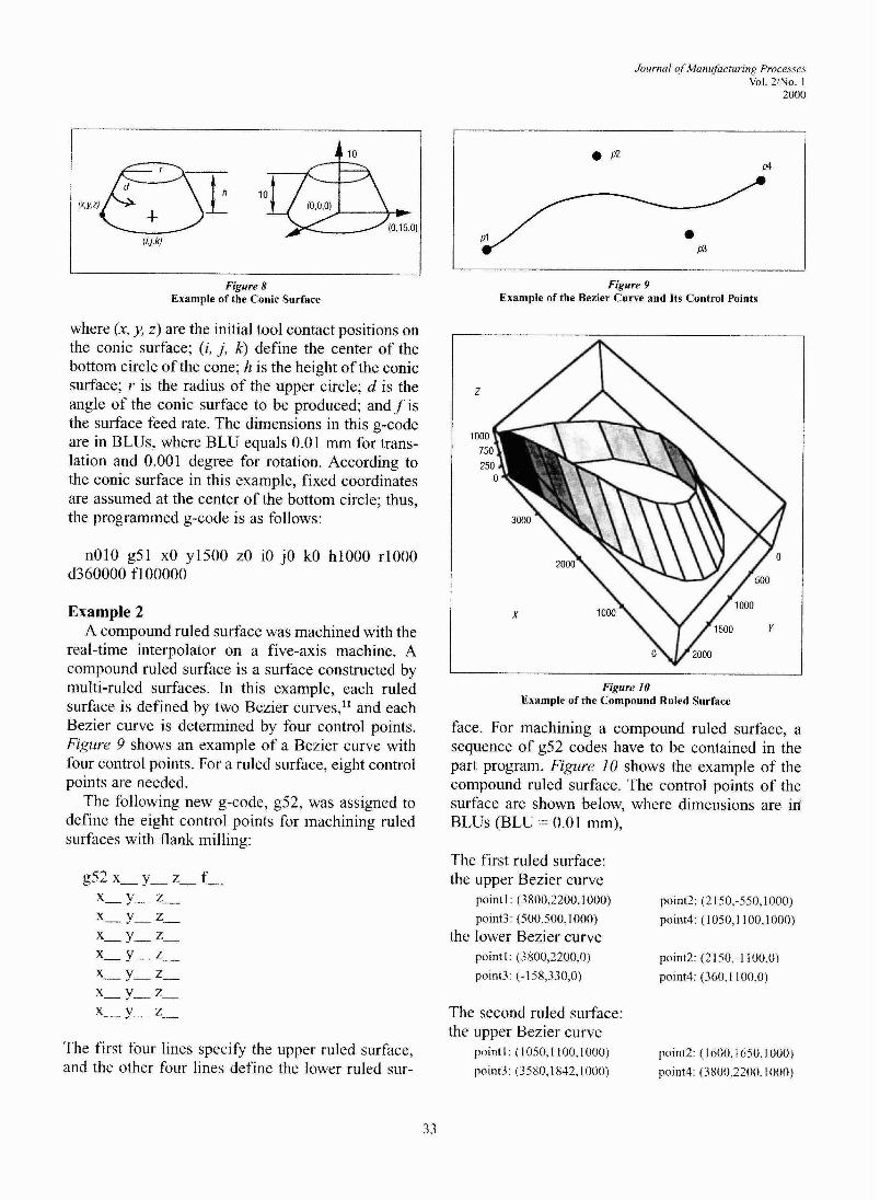
Example 1 The conic surface, shown in Figure 8, was
machined on a five-axis machine by a flank cutter with the developed real-time interpolator. To machine the conic surface, a new g-code, g5 1, was defined, as follows:
Jozrrnal of Manufacturing Processes Vol. 2Mo. 1
2000
Figure 8 Example of the Conic Surface
where (x, y, z) are the initial tool contact positions on the conic surface; (i, j, k) define the center of the bottom circle of the cone; h is the height of the conic surface; r is the radius of the upper circle; d is the angle of the conic surface to be produced; and f is the surface feed rate. The dimensions in this g-code are in BLUs, where BLU equals 0.01 mm for trans- lation and 0.001 degree for rotation. According to the conic surface in this example, fixed coordinates are assumed at the center of the bottom circle; thus, the programmed g-code is as follows:
Example 2 A compound ruled surface was machined with the
real-time interpolator on a five-axis machine. A compound ruled surface is a surface constructed by multi-ruIed surfaces. In this example, each ruled surface is defined by two Bezier curves," and each Bezier curve is determined by four control points. Figure 9 shows an example of a Bezier curve with four control points. For a ruled surface, eight control points are needed.
The following new g-code, g52, was assigned to define the eight control points for machining ruled surfaces with flank milling:
The first four lines specify the upper ruled surface, and the other four lines define the lower ruled sur-
Figure 9 Example of the Bezier Curve and Its Control Points
Figure 10 Example of the Compound Ruled Surface
face. For machining a compound ruled surface, a sequence of g52 codes have to be contained in the part program. Figure 10 shows the example of the compound ruled surface. The control points of the surface are shown below, where dimensions are in BLUs (BLU = 0.01 mm),
The first ruled surface: the upper Bezier curve
po~ntl (3800,2200,1000) po1nt2 (2 150,-550,1000)
point3 (500,500,1000) po1nt4 (1050,1100,1000) the lower Bezier curve
po~ntl (3800,2200.0) po1nt2 (2 150,- 1 100.0)
point3 (-1 58,330,O) point4 (360.1 100,O)
The second ruled surface: the upper Bezier curve
po~ntl (1050,1100,1000) po1nt2 (1 600,1650.1000) point3 (3580.1832.1000) point4 (3800,2200,1000)
Journal oj Manufacturing Processes Vol. 2Mo. I 2000
the lower Bezier curve po~ntl : (360,1100,0) point2: (878,1870,O)
polnt3: (28 10,1870,O) point4: (3800,2200,O)
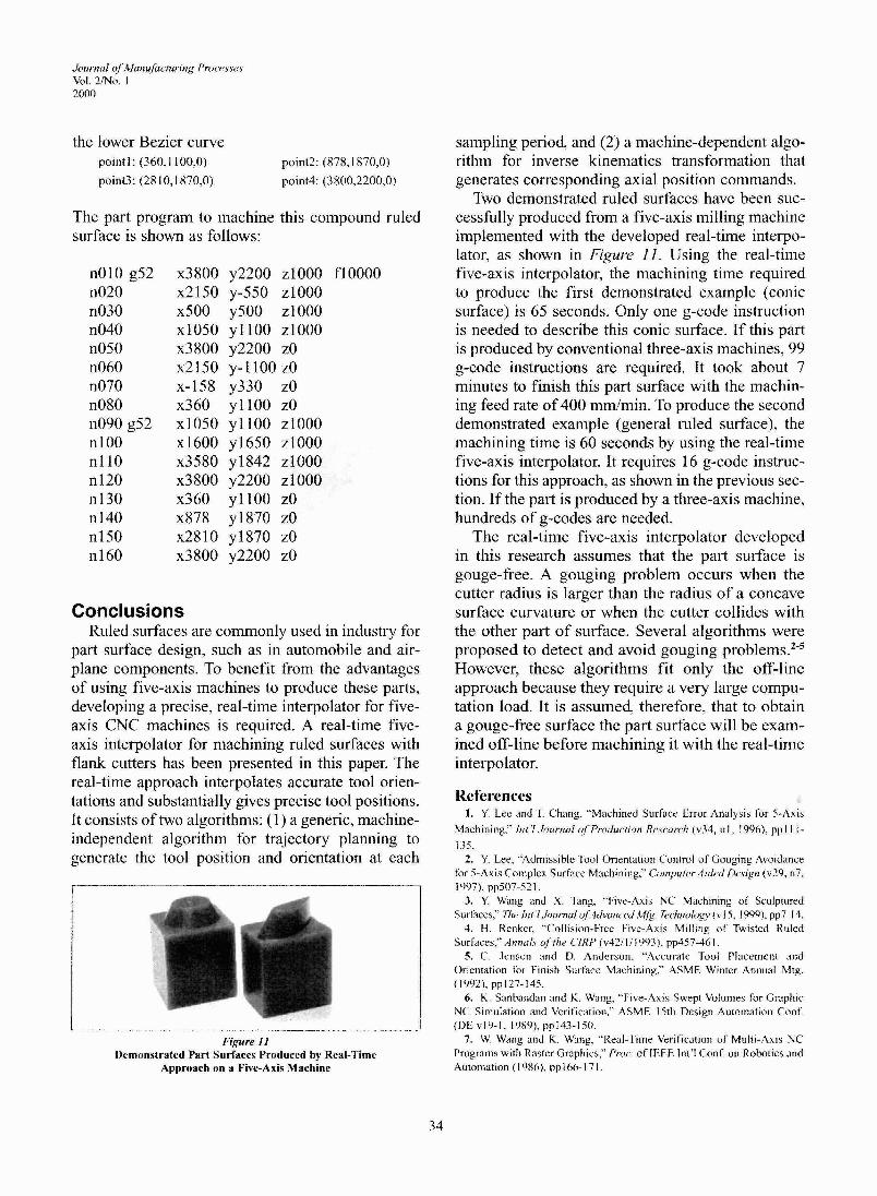
The part program to machine this compound ruled surface is shown as follows:
Conclusions Ruled surfaces are commonly used in industry for
part surface design, such as in automobile and air- plane components. To benefit from the advantages of using five-axis machines to produce these parts, developing a precise, real-time interpolator for five- axis CNC machines is required. A real-time five- axis interpolator for machining ruled surfaces with flank cutters has been presented in this paper. The real-time approach interpolates accurate tool orien- tations and substantially gives precise tool positions. It consists of two algorithms: (1) a generic, machine- independent algorithm for trajectory planning to generate the tool position and orientation at each
Figure I 1 Demonstrated Part Surfaces Produced by Real-Time
Approach on a Five-Axis Machine
sampling period, and (2) a machine-dependent algo- rithm for inverse kinematics transformation that generates corresponding axial position commands.
Two demonstrated ruled surfaces have been suc- cesshlly produced from a five-axis milling machine implemented with the developed real-time interpo- lator, as shown in Figure 11. Using the real-time five-axis interpolator, the machining time required to produce the first demonstrated example (conic surface) is 65 seconds. Only one g-code instruction is needed to describe this conic surface. If this part is produced by conventional three-axis machines, 99 g-code instructions are required. It took about 7 minutes to finish this part surface with the machin- ing feed rate of 400 mrnlmin. To produce the second demonstrated example (general ruled surface), the machining time is 60 seconds by using the real-time five-axis interpolator. It requires 16 g-code instruc- tions for this approach, as shown in the previous sec- tion. If the part is produced by a three-axis machine, hundreds of g-codes are needed.
The real-time five-axis interpolator developed in this research assumes that the part surface is gouge-free. A gouging problem occurs when the cutter radius is larger than the radius of a concave surface curvature or when the cutter collides with the other part of surface. Several algorithms were proposed to detect and avoid gouging However, these algorithms fit only the off-line approach because they require a very large compu- tation load. It is assumed, therefore, that to obtain a gouge-free surface the part surface will be exam- ined off-line before machining it with the real-time interpolator.
References 1. Y Lee and T Chang, "Machined Surface Error Analysrs for 5-Axis
Machlnlng," Itit 1 Jotrrnul ofProduc~lon Re5earth (v34. n l , 1996), pp111- 135
2. Y Lee, "Admiss~ble Tool Orlentatlon Controi of Gouging Avordan~e for AXIS Complex Surface Machlnlng." Comptrler 4ided Design (v29, n7 1997). pp507-52 1
3. Y Wang and X Tang, "FIV~-AXIS NC Mdchlning of Sculptured Surfaces:' The lnr 1 k > t ~ n u / ofAdtoncrd M& Gchnology (vl5, 1999). pp7- 14
4. H Renker. "Coll~s~on-Free F~ve-AXIS Mllllng of Tw~sted Ruled Surfaces: Annalr of the CIRP (v421111991), pp457-461
5. C Jensen and D Ander\on. "Accurate Tool Pldcernent dnd Onentallon for Finlsh Surface Machlmng.' ASMF W~nter Annudl Mrg (l 992), pp127- 145
6. K Sanbandan dnd K Wang. "F~ve-Ax15 'Swept Volumes for C~raph~c NC Slmulatlon dnd Ver~tlcdt~on,' ASME 15th Deslgn Automdtlon Conf (Dt v19-1. 1989), pp143-150
7. W Wang and K Wdng, "Real-Trme Vent~catlon ot Multi-AXIS NC Programs w ~ t h Raster Graphr~s," Ptoc of fPEt Int'l Conf on Robotrcz and Auromat~on ( I 986). pp 166-1 71
8. R. Lin and Y. Koren, "Real-Time Interpolators for Multi-Axis CNC Machine Tools," CIRP Journal ofMfg. Systems (v25, n2,1996), pp145-149.
9. D. Yang and T. Kong, "Parametric Interpolator Versus Linear Interpolator for Precision CNC Machining," Computer Aided Design (v26, n3, 1994), pp225-233.
10. J. Chou and D. Yang, "On the Generation of Coordinated Motion of Five-Axis CNCJCMM Machines," Journal of Engg. for Industry (v114, Feb. 1992), pp15-22.
11. Michacle E. Mortenson, Geometric Modeling (New York: Wiley Press, 1985).
12. M. Shpitalni, Y. Koren, and C.C. Lo, "Real-Time Curve Interpolator," Computer Aided Design (v26, nl I, 1994), pp832-838.
13. Y. Koren and R. Lin, "Five-Axis Surface Interpolators," Annals of the CZRP (v44/1/1995), pp379-382.
14. I. Faux and M. Pratt, Computational Geometry for Design and Mfg. (New York: John Wiley & Sons, 1981).
Journal of Manufacturing Processes Vol. 2mo. 1
2000
Authors' Biographies Rong-Shine Lin received his PhD in mechanical engineering and
applied mechanics from the University of Michigan in 1994. He worked for Chrysler Corporation as a tool and process engineer in the Dept. of Advanced Manufacturing Engineering from 1994 to 1995. He was an assis- tant professor of industrial engineering at Rutgers University from 1995 to 1997. Currently, he is an assistant professor in the Dept. of Mechanical Engineering at National Chung Cheng University (Taiwan). His research interests include five-axis CNCs, CAD/CAM/CNC, and rapid prototyping
Yoram Koren received a BSc and an MSc in electrical engineering and a DSc (1970) in mechanical engineering from the Technion-Israel Institute of Technology. He is the Paul G. Goebel Professor of Mechanical Engineering and Applied Mechanics at the University of Michigan. He is the author of many publications on automated manufacturing and is the inventor of work covered by three US patents in robotics.