
CNC MACHINING OF PROPELLERS TO BETTER THAN CLASS … · CNC MACHINING OF PROPELLERS TO BETTER ......
21
CNC MACHINING OF PROPELLERS TO BETTER THAN CLASS S TOLERANCES Bodo Gospodnetic
Transcript of CNC MACHINING OF PROPELLERS TO BETTER THAN CLASS … · CNC MACHINING OF PROPELLERS TO BETTER ......
CNC MACHINING OF PROPELLERS TO BETTER
THAN CLASS S TOLERANCES
Bodo Gospodnetic
CNC MACHINING OF PROPELLERS TO BETTER
THAN CLASS S TOLERANCES
Bodo Gospodnetic
Dominis Engineering Ltd. 5515 Canotek Rd., Unit 15
Gloucester, Ontario Canada K1J 9L1
tel.: (613) 747-0193
fax.: (613) 746-3321
Copyright © 2015 by SNAME

This paper was first presented on the 15th of September 2015 at
the 14th
Propeller and Shafting Symposium in Norfolk, Virginia, U.S.A.
Page 1 of 18
CNC MACHINING OF PROPELLERS TO BETTER
THAN CLASS S TOLERANCES
Slobodan (Bodo) Gospodnetic, Member
Dominis Engineering Ltd.
5515 Canotek Rd., Unit 15
Gloucester, Ontario
Canada K1J 9L1
Abstract Producing class S propellers and water jet impellers presents serious challenges for propeller manufacturers. To
overcome these challenges and consistently manufacture propellers with superior quality, an integrated approach
was adopted when developing and implementing a process for Computer Numerically Controlled (CNC) machining
of propeller surfaces. Highlights of this process are: (1) CNC machining of all blade surfaces; extreme surface
blending, (2) CNC machining to final form & finish without hand grinding and (3) high precision, better than class
S. This paper will describe various challenges encountered in the production of CP propeller blades and how these
challenges were overcome in order to produce accurate CP propeller blades which exceed class S tolerances.
INTRODUCTION
Computer Numerically Controlled (CNC) machining
of propeller blades was pioneered in the 1970’s by
KaMeWa (AB Karlstad Mekaniska Werstads) in
Sweden and in the1980’s by the Bird Johnson
Company (now Rolls-Royce Naval Marine) in
Walpole Mass. Papers by Donald E. Ridley (1) and
by Mark F. Nittel (2) give a comprehensive overview
of the implementation of a blade machining facility
in Walpole Mass. During the last 20 – 25 years CNC
milling machines have been generally accepted as the
preferred way of machining of propellers and
propeller blades. Even with this wide acceptance of
CNC machining technique, producing a propeller or a
propeller blade with class S tolerances remains a
challenge.
Class S tolerances are the tightest tolerances in ISO
484/1 (3) and ISO 484/2 (4) manufacturing standards
for propellers. Propellers meeting class S tolerances
represented the best that propeller manufacturers
could achieve in the 20th
century within the prices
that governments would pay for quiet naval
propellers. The demand for quiet propellers has
grown with the cruise ship business and Dominis
anticipates that the desire for even quieter propellers
will grow too. Dominis also believes that with
advances in manufacturing and enhancements in the
production process, propellers made to better than
class S tolerances could be produced for about the
same price. Therefore, let us see then what type of
manufacturing process would guarantee production
of propellers with precision exceeding class S
tolerances.
When developing this new process, all aspects of the
existing manufacturing processes which can
potentially influence the precision of the end result
were re-assessed. Possible improvements were
identified, and benefits of these improvements were
evaluated and implemented. The following
enhancements to the propeller manufacturing process
were implemented: propeller surface representation,
fixturing, tooling and CNC tool path generation.
Hand grinding of residual scallops left by milling
cutters on propeller blade surfaces was assessed as an
important source of variability and inconsistencies in
finish machined propeller surfaces. Therefore, hand
grinding was eliminated from the propeller
manufacturing process.
The ultimate goal of this new propeller
manufacturing process is CNC machining of all
propeller blade surfaces in such a way that after the
propeller blade is removed from the milling machine,
there is no need for any additional hand finishing. In
6-1
Page 2 of 18
other words, if the surface geometry and roughness
specified by propeller designer was met by the CNC
programs without additional hand finishing steps,
then it can be said that propeller blade was CNC
machined to “final form and finish” (7).
This paper will describe the various challenges and
successes in implementing this new propeller
manufacturing process for CNC machining of
Controllable Pitch (CP) propeller blades. This
protocol was used with great success in the
production of several sets of CP propeller blades for
the Halifax Class Canadian Patrol Frigates (CPF)
program and CP blades for USCG 210 foot cutters.
MACHINING TO FINAL FORM AND
FINISH
We use the following descriptive definition for “final
form and finish”: final form of a propeller is defined
by the propeller’s table of off-sets and/or by its CAD
solid model, while finish is the desired final surface
roughness of the propeller. We are typically asked to
meet tolerances of a particular propeller class as
specified by ISO 484/1 and ISO 484/2.
We feel that the final form of a propeller surface is
best achieved by CNC machining of the CP propeller
blade in a vertical position. Precision of the surface
geometry depends on several factors:
1, Precision of machining fixture
2, Blade bending due to stress relieving of
propeller blade casting
3, Blade bending due to machining forces
4, Cutter wear
Precision of the machining fixture is of paramount
importance and no effort should be spared in
achieving flatness of the bolting surface and
perpendicularity of dowel holes used for locating and
pinning the propeller blade casting on the fixture. In
our experience the effects of stress relieving during
rough machining are minimal if the propeller blade is
machined in several surface bands where the pressure
side of the band is machined immediately after the
suction side of the band. During finish machining,
blade bending due to machining forces is negligible.
Cutter wear could play a role only during finish
machining. However when machining Ni-Al-bronze
propeller blades we have not experienced major
problems with cutter wear.
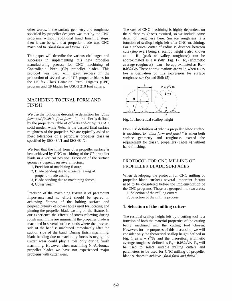
The cost of CNC machining is highly dependent on
the surface roughness required, so we include some
detail on roughness here. Surface roughness is a
function of scallop height left after CNC machining.
For a spherical cutter of radius r, distance between
cuts (step over) being s, scallop height ε also known
as Rt (peak to valley roughness) can be
approximated as ε = s2/8r (Fig. 1). Ra (arithmetic
average roughness) can be approximated as Ra =
0.032s2/r. These approximations are valid when ε « r.
For a derivation of this expression for surface
roughness see Qu and Shih (5).
Fig. 1, Theoretical scallop height
Dominis’ definition of when a propeller blade surface
is machined to “final form and finish” is when both
surface geometry and roughness exceed the
requirement for class S propellers (Table 4) without
hand finishing.
PROTOCOL FOR CNC MILLING OF
PROPELLER BLADE SURFACES
When developing the protocol for CNC milling of
propeller blade surfaces several important factors
need to be considered before the implementation of
the CNC programs. These are grouped into two areas:
1, Selection of the milling cutters
2, Selection of the milling process
1. Selection of the milling cutters
The residual scallop height left by a cutting tool is a
function of both the material properties of the casting
being machined and the cutting tool chosen.
However, for the purposes of this discussion, we will
consider only the theoretical scallop height defined in
Fig. 1 as ε = s2/8r and the theoretical arithmetic
average roughness defined as Ra = 0.032s2/r. Ra will
be used to select suitable milling cutters and
parameters to be used for CNC milling of propeller
blade surfaces to achieve “final form and finish”.
6-2
Page 3 of 18
After extensive experimentation and testing of ball
nose cutters of different types and diameters, cutters
suitable for rough and finish milling operations of
propeller blade surfaces were selected (see Table 1).
Table 1. ε and Ra for given cutter dia. and step over
Rough
milling
Finish
milling
Cutter diameter, d, inch 2 1.25
Step over, s, inch 0.197 0.025
Scallop height, ε, inch 0.0048 0.00012
Surface roughness Ra, µinch 1240 31
From Table 1 it can be seen that the target surface
roughness required for class S propellers can be
exceeded by using a 1.25 inch diameter ball nose
cutter. Using the 1.25” dia. ball nose cutter with a
step over of 0.625 mm (0.025 inch) will in theory
produce a surface finish (Ra) of approximately 31
µinch. Since the formulae that we are using for
computation of theoretical scallop height ε and
theoretical average surface roughness Ra are
approximations, the actual surface roughness after
CNC milling will probably be of poorer quality and
Ra somewhat greater than 31 µinch. The
measurement of the surface roughness after milling
will confirm the actual surface roughness obtained by
the CNC protocol implemented during
manufacturing. The ball nose cutter selected for
finish milling has a single round, center cutting,
carbide insert with two cutting edges. Inserts for this
cutter are precision ground with tolerance of
±0.00025 inch on the radius.
Selection of depth of cut for rough milling and finish
milling will be affected by the amount and
distribution of extra material on the casting. The extra
material on the propeller blade casting has to be
removed first by rough milling and then by finish
milling. Ideally, there should be only one roughing
and one finishing pass. However, if there is a
substantial amount of extra material on the casting or
if extra material on the casting is not evenly
distributed, more than one roughing pass will have to
be applied in order to bring the rough milled surface
down to the ideal amount of extra material for the
finishing pass.
What is the ideal amount of extra material to be
removed during finish milling pass? Testing of 1.25
inch diameter ball nose cutter under different milling
scenarios has shown that excellent results in terms of
surface finish and speed of milling can be achieved
with depths of cut between 0.060 inch and 0.080 inch
(1.5 mm to 2 mm). The 1.25” in dia. ball nose cutter
was used at feed rates up to 6 m/min. When tested,
the following parameters were used: rpm = 6285,
depth of cut 0.060 inch, width of cut of 0.025 inch.
The milling machine used for testing has a spindle
with a maximum rotational speed of 8000 rpm, with a
maximum programmable feed rate of 6 m/min and
rapid return rate of 10 m/min. Therefore, any
combinations of feed rate and speed which exceed 6
m/min could not be tested and evaluated. The milling
machine was thus the limiting factor for the speed of
finish milling.
2. Selection of the milling process
Direction of CNC milling was chosen to always be in
the direction of climb milling. Consequently the
cutter will be in the air during the return trajectory to
the starting point of the next cut step. Milling during
the return travel was briefly considered and rejected
as the cut produced by return milling was of inferior
quality to the cut produced by climb milling.
Selection of the geometry of the tool path is critical
to the quality of the CNC protocol. Radial section,
horizontal and vertical tool path trajectories were
considered. Of these we have selected radial section
cuts for CNC milling of the pressure side (PS) and
the suction side (SS) propeller blade surfaces. This
seemed the most logical approach since both the PS
and the SS surfaces of propeller blades are defined at
radial sections. The CAD surfaces used for creation
of tool paths are created from radial sections which
are defined by the table of off-sets and pitch, rake and
skew distributions.
Since leading and trailing edges are defined at the
same radial sections which define the PS and SS
surfaces, leading edge (LE), trailing edge (TE) and
anti-singing chamfer will be CNC milled in the same
tool path as the PS and the SS of the propeller blade.
All propeller blade surfaces were to be CNC milled
to + 0.020” dimension of target. This 0.5 mm, evenly
distributed, extra thickness per side will increase
propeller blade lifespan by providing additional
material for future polishing during regular propeller
cleaning and maintenance cycles.
The tip of the propeller blade (from r/R = 0.975) was
machined with a smaller step-over between cuts in
6-3
Page 4 of 18
order to reduce the scallop heights there at the
leading and trailing edges.
MANUFACTURING PROCESS FOR CNC
MACHINING OF CP PROPELLER
BLADES
Machining of CP propeller blades is most
conveniently done on a horizontal milling machine.
For illustration purposes, a CNC propeller
manufacturing process shall be described which was
developed for machining of CP propeller blades for
the Halifax Class Canadian Patrol Frigates (CPF).
The manufacturing process for CPF propeller blades
consists of four distinct operations:
1, Rough milling of the trunnion;
2, Rough milling of blade, fillet and palm
surfaces;
3, Finish milling of blade, fillet and palm
surfaces, and
4, Finish milling of the trunnion
The propeller blade trunnion is machined with the
propeller blade casting mounted and secured in a
special fixture which holds the propeller blade in a
horizontal orientation providing unhindered access to
the propeller blade foot and overhang. Trunnion OD,
blade overhang if any, trunnion seal surfaces, dowel
holes, bolt holes and counter bores are machined
while the propeller blade is in its horizontal
orientation. Propeller blade surfaces, fillets and palm
are machined with the propeller blade bolted and
pinned in the vertical orientation on a fixture attached
to the horizontal rotary table of the milling machine.
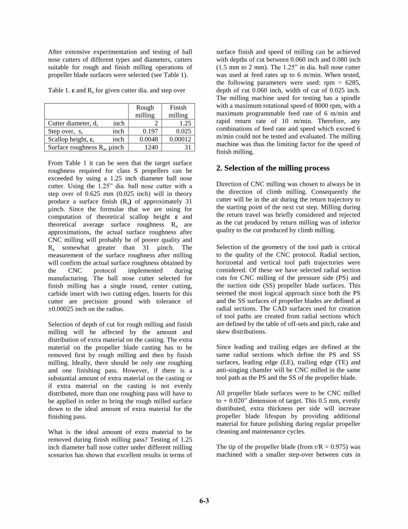
Operation 1: Rough milling of the
trunnion
Rough milling of the trunnion (Fig. 2) is an operation
which consists of standard shop activities such as
drilling, taping, facing and boring. However, facing
of the trunnion bottom (the blade reference plane)
surface and boring of dowel holes, two features
which are used for locating and securing the blade on
the vertical fixture, must be done with maximum care
and accuracy. Precision of the propeller blade
surfaces depends on the flatness of the blade
reference plane, perpendicularity of dowel holes to
the blade reference plane and precision of dowel hole
locations on the trunnion. It is also important to note
that the reference plane surface, dowel holes and the
trunnion OD will at this stage be finish machined to a
known plus dimension.
The back-counterboring of the trunnion bolt holes
presents additional challenges. This task requires
special tools which have been custom designed and
manufactured by Dominis Engineering.
Fig. 2, Rough milling of the trunnion
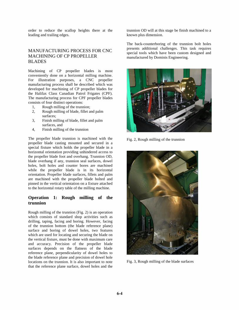
Fig. 3, Rough milling of the blade surfaces
6-4
Page 5 of 18
Operation 2: Rough milling of blade, fillet
and palm surfaces
The rough milling of blade surfaces (Fig. 3) consists
of 4 distinct tasks:
a) Rough milling of the blade contour using a 3
inch dia. shell mill cutter;
b) Rough milling of PS and SS surfaces using a 2
inch dia. ball nose cutter;
c) Rough milling of the palm using a 4 inch dia.
button mill cutter, and
d) Rough milling of fillets using a 2 inch dia. ball
nose cutter.
All blade surfaces were rough milled with 5 mm step-
over. All rough milling of radial sections is done
using climb milling with cuts starting at the TE and
ending at the LE, or vice versa depending on blade
side and blade orientation.
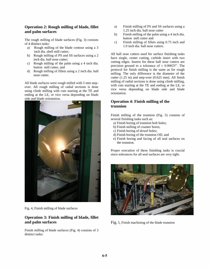
Fig. 4, Finish milling of blade surfaces
Operation 3: Finish milling of blade, fillet
and palm surfaces
Finish milling of blade surfaces (Fig. 4) consists of 3
distinct tasks:
a) Finish milling of PS and SS surfaces using a
1.25 inch dia. ball nose cutter
b) Finish milling of the palm using a 4 inch dia.
button mill cutter and
c) Finish milling of fillets using 0.75 inch and
1.0 inch dia. ball nose cutters.
All ball nose cutters used for surface finishing tasks
have single, center cutting, carbide insert with two
cutting edges. Inserts for these ball nose cutters are
precision ground to a tolerance of ± 0.00025”. The
protocol for finish milling is the same as for rough
milling. The only difference is the diameter of the
cutter (1.25 in) and step-over (0.625 mm). All finish
milling of radial sections is done using climb milling,
with cuts starting at the TE and ending at the LE, or
vice versa depending on blade side and blade
orientation.
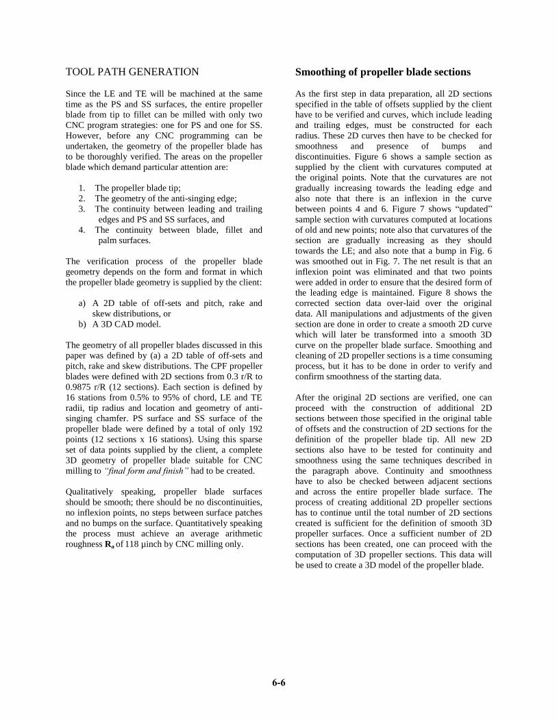
Operation 4: Finish milling of the
trunnion
Finish milling of the trunnion (Fig. 5) consists of
several finishing tasks such as:
a) Finish boring of trunnion bolt holes;
b) Finish milling of counter bores;
c) Finish boring of dowel holes;
d) Finish boring of the trunnion OD, and
e) Finish boring and facing of all seal surfaces on
the trunnion.
Proper execution of these finishing tasks is crucial
since tolerances for all seal surfaces are very tight.
Fig. 5, Finish machining of the blade trunnion
6-5
Page 6 of 18
TOOL PATH GENERATION
Since the LE and TE will be machined at the same
time as the PS and SS surfaces, the entire propeller
blade from tip to fillet can be milled with only two
CNC program strategies: one for PS and one for SS.
However, before any CNC programming can be
undertaken, the geometry of the propeller blade has
to be thoroughly verified. The areas on the propeller
blade which demand particular attention are:
1. The propeller blade tip;
2. The geometry of the anti-singing edge;
3. The continuity between leading and trailing
edges and PS and SS surfaces, and
4. The continuity between blade, fillet and
palm surfaces.
The verification process of the propeller blade
geometry depends on the form and format in which
the propeller blade geometry is supplied by the client:
a) A 2D table of off-sets and pitch, rake and
skew distributions, or
b) A 3D CAD model.
The geometry of all propeller blades discussed in this
paper was defined by (a) a 2D table of off-sets and
pitch, rake and skew distributions. The CPF propeller
blades were defined with 2D sections from 0.3 r/R to
0.9875 r/R (12 sections). Each section is defined by
16 stations from 0.5% to 95% of chord, LE and TE
radii, tip radius and location and geometry of anti-
singing chamfer. PS surface and SS surface of the
propeller blade were defined by a total of only 192
points (12 sections x 16 stations). Using this sparse
set of data points supplied by the client, a complete
3D geometry of propeller blade suitable for CNC
milling to “final form and finish” had to be created.
Qualitatively speaking, propeller blade surfaces
should be smooth; there should be no discontinuities,
no inflexion points, no steps between surface patches
and no bumps on the surface. Quantitatively speaking
the process must achieve an average arithmetic
roughness Ra of 118 µinch by CNC milling only.
Smoothing of propeller blade sections
As the first step in data preparation, all 2D sections
specified in the table of offsets supplied by the client
have to be verified and curves, which include leading
and trailing edges, must be constructed for each
radius. These 2D curves then have to be checked for
smoothness and presence of bumps and
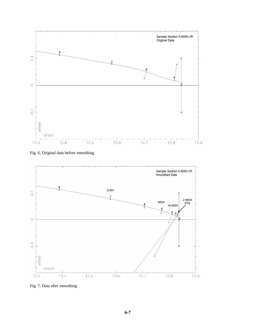
discontinuities. Figure 6 shows a sample section as
supplied by the client with curvatures computed at
the original points. Note that the curvatures are not
gradually increasing towards the leading edge and
also note that there is an inflexion in the curve
between points 4 and 6. Figure 7 shows “updated”
sample section with curvatures computed at locations
of old and new points; note also that curvatures of the
section are gradually increasing as they should
towards the LE; and also note that a bump in Fig. 6
was smoothed out in Fig. 7. The net result is that an
inflexion point was eliminated and that two points
were added in order to ensure that the desired form of
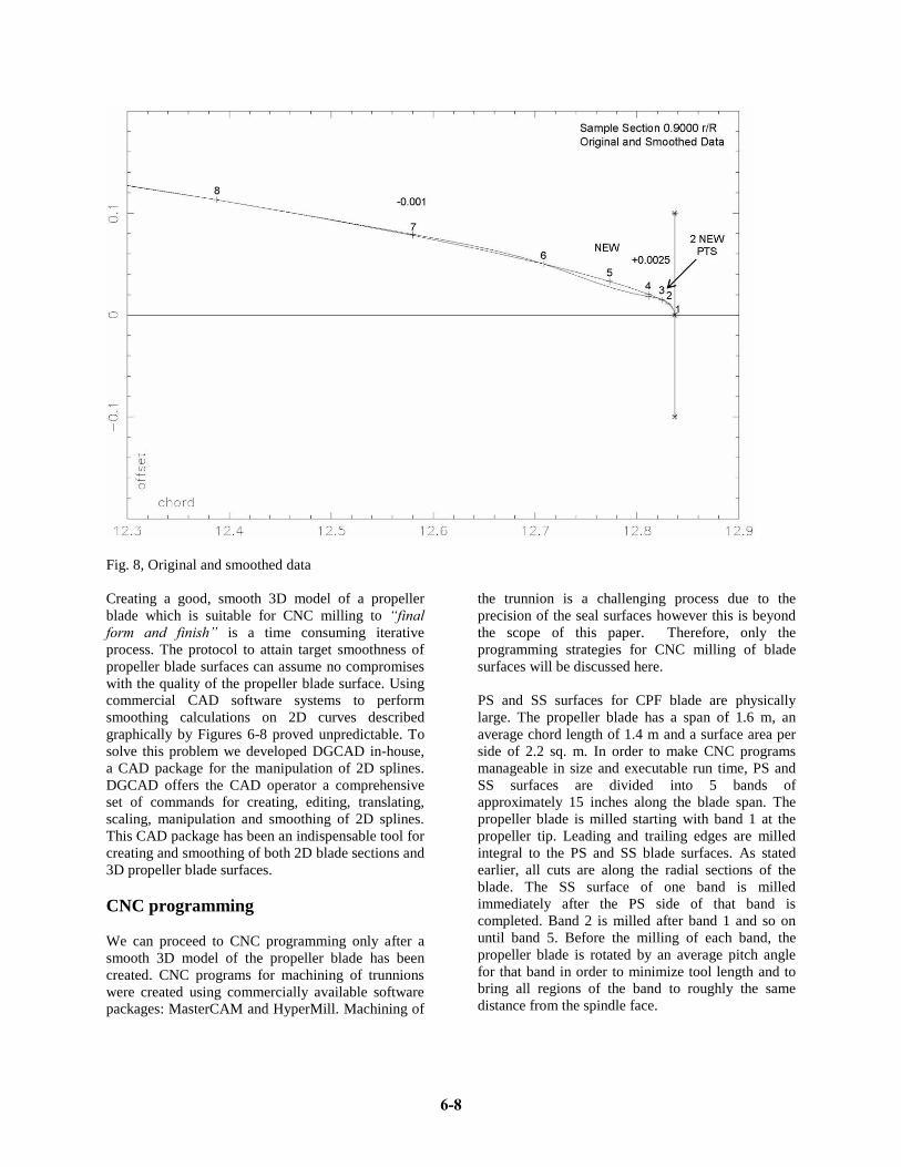
the leading edge is maintained. Figure 8 shows the
corrected section data over-laid over the original
data. All manipulations and adjustments of the given
section are done in order to create a smooth 2D curve
which will later be transformed into a smooth 3D
curve on the propeller blade surface. Smoothing and
cleaning of 2D propeller sections is a time consuming
process, but it has to be done in order to verify and
confirm smoothness of the starting data.
After the original 2D sections are verified, one can
proceed with the construction of additional 2D
sections between those specified in the original table
of offsets and the construction of 2D sections for the
definition of the propeller blade tip. All new 2D
sections also have to be tested for continuity and
smoothness using the same techniques described in
the paragraph above. Continuity and smoothness
have to also be checked between adjacent sections
and across the entire propeller blade surface. The
process of creating additional 2D propeller sections
has to continue until the total number of 2D sections
created is sufficient for the definition of smooth 3D
propeller surfaces. Once a sufficient number of 2D
sections has been created, one can proceed with the
computation of 3D propeller sections. This data will
be used to create a 3D model of the propeller blade.
6-6
Page 7 of 18
Fig. 6, Original data before smoothing
Fig. 7, Data after smoothing
6-7
Page 8 of 18
Fig. 8, Original and smoothed data
Creating a good, smooth 3D model of a propeller
blade which is suitable for CNC milling to “final
form and finish” is a time consuming iterative
process. The protocol to attain target smoothness of
propeller blade surfaces can assume no compromises
with the quality of the propeller blade surface. Using
commercial CAD software systems to perform
smoothing calculations on 2D curves described
graphically by Figures 6-8 proved unpredictable. To
solve this problem we developed DGCAD in-house,
a CAD package for the manipulation of 2D splines.
DGCAD offers the CAD operator a comprehensive
set of commands for creating, editing, translating,
scaling, manipulation and smoothing of 2D splines.
This CAD package has been an indispensable tool for
creating and smoothing of both 2D blade sections and
3D propeller blade surfaces.
CNC programming
We can proceed to CNC programming only after a
smooth 3D model of the propeller blade has been
created. CNC programs for machining of trunnions
were created using commercially available software
packages: MasterCAM and HyperMill. Machining of
the trunnion is a challenging process due to the
precision of the seal surfaces however this is beyond
the scope of this paper. Therefore, only the
programming strategies for CNC milling of blade
surfaces will be discussed here.
PS and SS surfaces for CPF blade are physically
large. The propeller blade has a span of 1.6 m, an
average chord length of 1.4 m and a surface area per
side of 2.2 sq. m. In order to make CNC programs
manageable in size and executable run time, PS and
SS surfaces are divided into 5 bands of
approximately 15 inches along the blade span. The
propeller blade is milled starting with band 1 at the
propeller tip. Leading and trailing edges are milled
integral to the PS and SS blade surfaces. As stated
earlier, all cuts are along the radial sections of the
blade. The SS surface of one band is milled
immediately after the PS side of that band is
completed. Band 2 is milled after band 1 and so on
until band 5. Before the milling of each band, the
propeller blade is rotated by an average pitch angle
for that band in order to minimize tool length and to
bring all regions of the band to roughly the same
distance from the spindle face.
6-8
Page 9 of 18
The actual CNC milling programs are generated
using the DGCAM software package. DGCAM was
developed in-house in order to facilitate generation of
large CNC programs required for CNC milling to
“final form and finish”. Input to DGCAM are data
representing surfaces and splines generated by the
DGCAD software and the parameters of the milling
protocol, i.e. serial numbers of the first and the last
radial sections, depth of cut, step-over, milling cutter
diameter, milling parameters etc. Except for minor
differences in the first and the last radial section to be
cut for each band, rough milling and finish milling
programs are machining the same surface bands
using different cutters, different depth of cut and
different step overs. Milling parameters for rough
milling and finish milling are given in Table 2. After
the CNC programs are created they are processed by
the DGPOST_R16 post processor software which
prepares NC code for the milling machine to be used
for milling of the propeller blade. Before CNC
programs can be allowed to run on the milling
machine, they have to be verified under full machine
simulation using the VERICUT software. CNC
programs are verified while milling a model of the
propeller blade casting mounted on the model of the
actual machining fixture.
Table 2, Parameters for rough and finish milling
Milling parameters Rough
milling
Finish
milling
Cutter diameter, inch 2 1.25
Step over, inch 0.197 0.025
Depth of cut, mm 6 – 8 1.5
Speed, rpm 3015 6285
Feed rate, m/min 1.2 6
CNC MILLING OF PROPELLER
BLADES
The CPF propeller blades were CNC machined on a
4-axis horizontal boring milling machine with a
working envelope of 2.5 m x 1.8 m x 1.4 m. This
milling machine has an 8000 rpm spindle,
programmable feed rate of up to 6 m/min and rapid
travel of 10 m/min in X, Y, Z axes, a programmable
(W-axis) quill 200 mm in dia. by 450 mm long and a
rotary table of 6 ton capacity with a maximum
rotational feed rate of 2 rpm. The controller of the
machine has large look ahead buffer which, for a
given curvature of the tool path, enables CNC milling
with maximum feed rates and minimum following
error. The milling machine is laser calibrated each
year. Positional accuracy on all linear axes of the
milling machine is in the order of ±0.004 mm.
Table 3, Rough and finish milling timing
Description Rough
milling
Finish
milling
PS SS PS SS
No. of cuts 340 340 2560 2560
Length of cuts, m 476 476 3584 3584
Cutting time, hours 7 7 12.8 12.8
Return time, hours 1.2 1.2 8.8 8.8
Total time, hours 8.2 8.2 21.6 21.6
Grand total time, hours 59.6
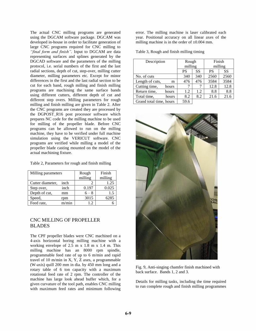
Fig. 9, Anti-singing chamfer finish machined with
back surface. Bands 1, 2 and 3.
Details for milling tasks, including the time required
to run complete rough and finish milling programmes
6-9
Page 10 of 18
for PS and SS surfaces are given in Table 3. For most
of the propeller blade castings, with no more than 8-
10 mm of extra material somewhat evenly
distributed, rough and finish milling of CPF propeller
blade surfaces was accomplished in 60 hours. Except
for indexing of propeller blade from PS to SS after
milling is completed for each band of propeller blade
surfaces which has to be performed by an operator,
the entire process is run unattended. Before finish
milling programs could be run on a propeller blade, a
sequence of special warm up programs for all axes
has to be run for several hours so that the milling
machine can reach its steady state temperature. Once
started, finish milling programs run continuously
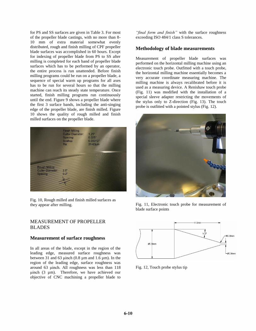
until the end. Figure 9 shows a propeller blade where
the first 3 surface bands, including the anti-singing
edge of the propeller blade, are finish milled. Figure
10 shows the quality of rough milled and finish
milled surfaces on the propeller blade.
Fig. 10, Rough milled and finish milled surfaces as
they appear after milling.
MEASUREMENT OF PROPELLER
BLADES
Measurement of surface roughness
In all areas of the blade, except in the region of the
leading edge, measured surface roughness was
between 31 and 63 μinch (0.8 µm and 1.6 µm). In the
region of the leading edge, surface roughness was
around 63 μinch. All roughness was less than 118
μinch (3 µm). Therefore, we have achieved our
objective of CNC machining a propeller blade to
“final form and finish” with the surface roughness
exceeding ISO 484/1 class S tolerances.
Methodology of blade measurements
Measurement of propeller blade surfaces was
performed on the horizontal milling machine using an
electronic touch probe. Outfitted with a touch probe,
the horizontal milling machine essentially becomes a
very accurate coordinate measuring machine. The
milling machine is always recalibrated before it is
used as a measuring device. A Renishaw touch probe
(Fig. 11) was modified with the installation of a
special sleeve adapter restricting the movements of
the stylus only to Z-direction (Fig. 13). The touch
probe is outfitted with a pointed stylus (Fig. 12).
Fig. 11, Electronic touch probe for measurement of
blade surface points
Fig. 12, Touch probe stylus tip
6-10
Page 11 of 18
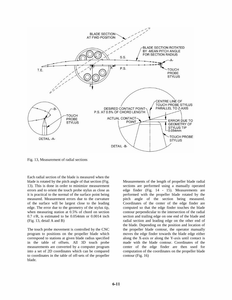
Fig. 13, Measurement of radial sections
Each radial section of the blade is measured when the
blade is rotated by the pitch angle of that section (Fig.
13). This is done in order to minimize measurement
errors and to orient the touch probe stylus as close as
it is practical to the normal of the surface point being
measured. Measurement errors due to the curvature
of the surface will be largest close to the leading
edge. The error due to the geometry of the stylus tip,
when measuring station at 0.5% of chord on section
0.7 r/R, is estimated to be 0.054mm or 0.0014 inch
(Fig. 13, detail A and B)
The touch probe movement is controlled by the CNC
program to positions on the propeller blade which
correspond to stations at given blade radius specified
in the table of offsets. All 3D touch probe
measurements are converted by a computer program
into a set of 2D coordinates which can be compared
to coordinates in the table of off-sets of the propeller
blade.
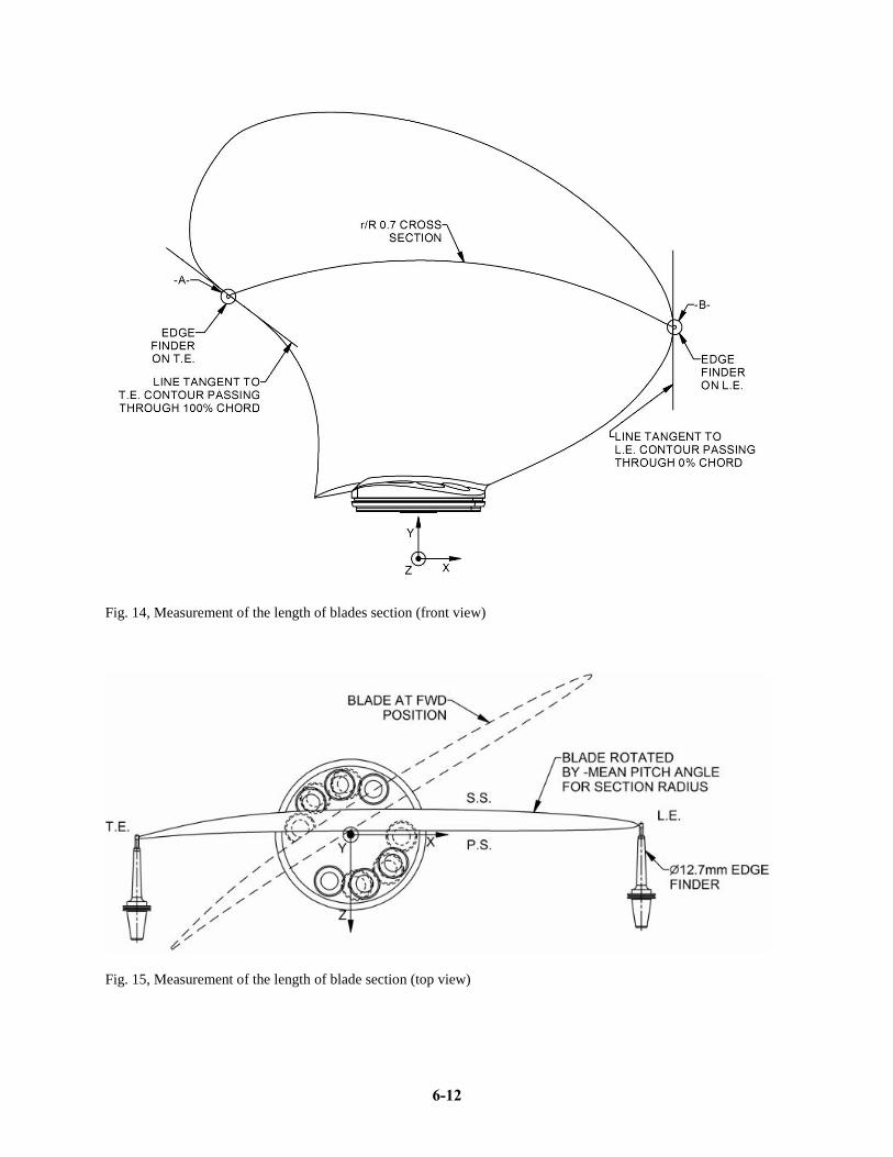
Measurements of the length of propeller blade radial
sections are performed using a manually operated
edge finder (Fig. 14 - 15). Measurements are
performed with the propeller blade rotated by the
pitch angle of the section being measured.
Coordinates of the center of the edge finder are
computed so that the edge finder touches the blade
contour perpendicular to the intersection of the radial
section and trailing edge on one end of the blade and
radial section and leading edge on the other end of
the blade. Depending on the position and location of
the propeller blade contour, the operator manually
moves the edge finder towards the blade edge either
along the X-axis or along the Y-axis until contact is
made with the blade contour. Coordinates of the
center of the edge finder are then used for
computation of the coordinates on the propeller blade
contour (Fig. 16)
6-11
Page 12 of 18
Fig. 14, Measurement of the length of blades section (front view)
Fig. 15, Measurement of the length of blade section (top view)
6-12
Page 13 of 18
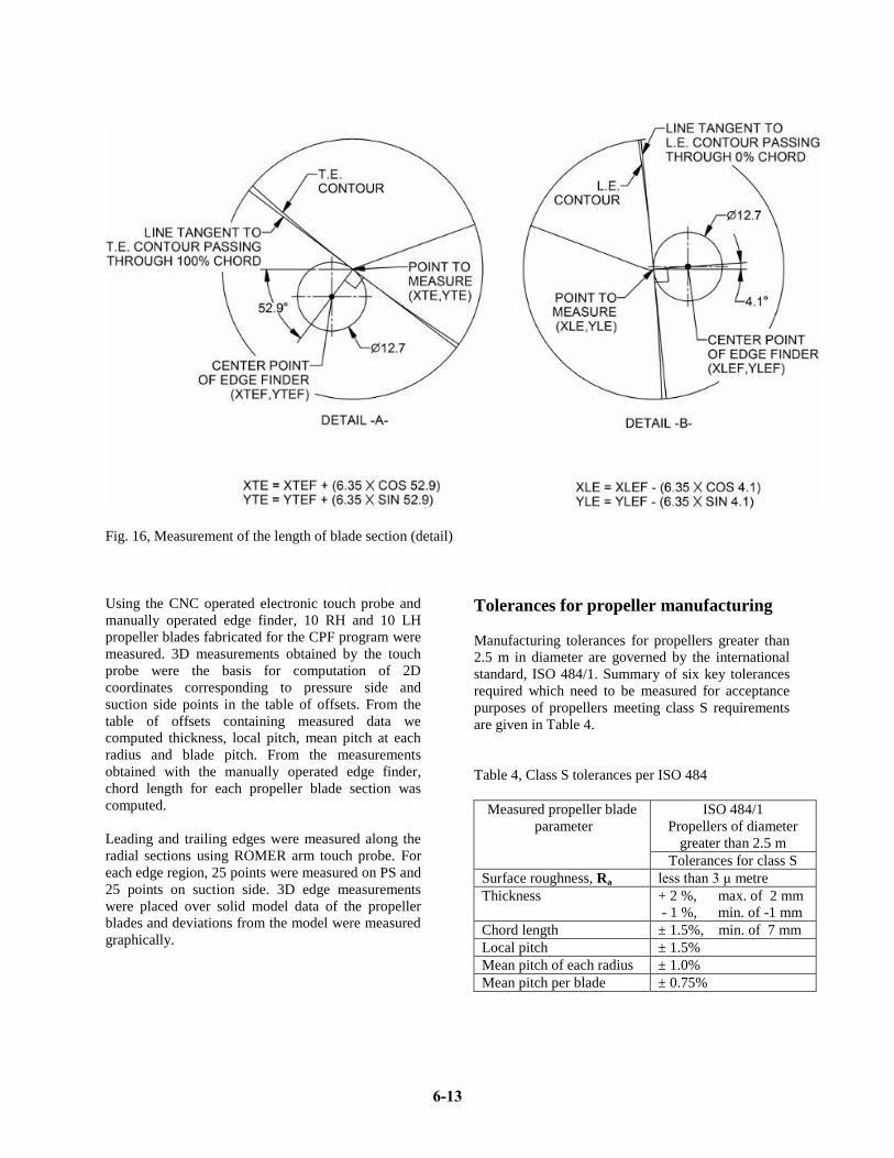
Fig. 16, Measurement of the length of blade section (detail)
Using the CNC operated electronic touch probe and
manually operated edge finder, 10 RH and 10 LH
propeller blades fabricated for the CPF program were
measured. 3D measurements obtained by the touch
probe were the basis for computation of 2D
coordinates corresponding to pressure side and
suction side points in the table of offsets. From the
table of offsets containing measured data we
computed thickness, local pitch, mean pitch at each
radius and blade pitch. From the measurements
obtained with the manually operated edge finder,
chord length for each propeller blade section was
computed.
Leading and trailing edges were measured along the
radial sections using ROMER arm touch probe. For
each edge region, 25 points were measured on PS and
25 points on suction side. 3D edge measurements
were placed over solid model data of the propeller
blades and deviations from the model were measured
graphically.
Tolerances for propeller manufacturing
Manufacturing tolerances for propellers greater than
2.5 m in diameter are governed by the international
standard, ISO 484/1. Summary of six key tolerances
required which need to be measured for acceptance
purposes of propellers meeting class S requirements
are given in Table 4.
Table 4, Class S tolerances per ISO 484
Measured propeller blade
parameter
ISO 484/1
Propellers of diameter
greater than 2.5 m
Tolerances for class S
Surface roughness, Ra less than 3 μ metre
Thickness
+ 2 %, max. of 2 mm
- 1 %, min. of -1 mm
Chord length ± 1.5%, min. of 7 mm
Local pitch ± 1.5%
Mean pitch of each radius ± 1.0%
Mean pitch per blade ± 0.75%
6-13
Page 14 of 18
Evaluation of measurements
Measurements for 10 RH and 10 LH propeller blades
were analysed and deviations of measured values
from design values were computed for seven key
propeller blade parameters:
1. Face (pressure side) coordinates
2. Back (suction side) coordinates
3. Thickness
4. Chord length
5. Local pitch
6. Mean pitch at each radius
7. Blade pitch
The ISO standard does not provide explicit tolerances
for coordinates on the face and back of the propeller
blades. However, measurements of coordinates on
propeller blade surfaces are used for the computation
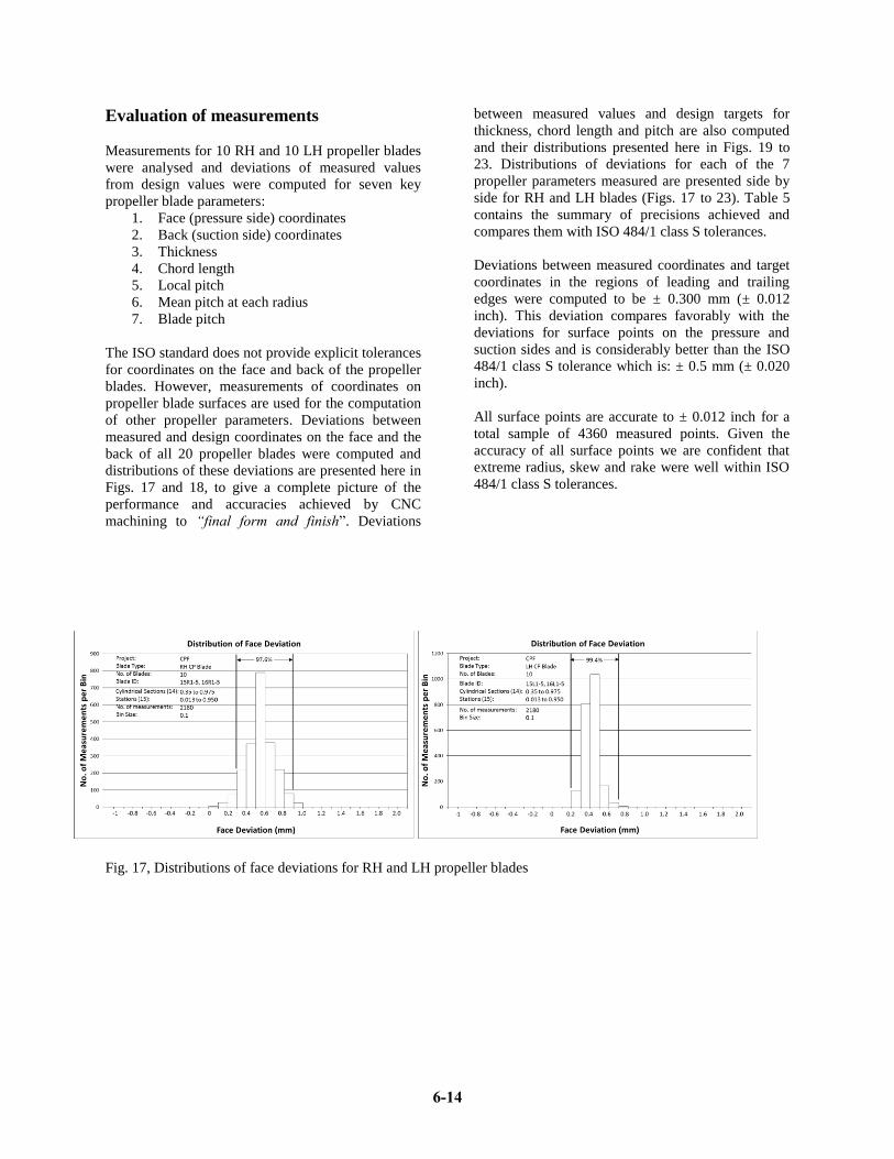
of other propeller parameters. Deviations between
measured and design coordinates on the face and the
back of all 20 propeller blades were computed and
distributions of these deviations are presented here in
Figs. 17 and 18, to give a complete picture of the
performance and accuracies achieved by CNC
machining to “final form and finish”. Deviations
between measured values and design targets for
thickness, chord length and pitch are also computed
and their distributions presented here in Figs. 19 to
23. Distributions of deviations for each of the 7
propeller parameters measured are presented side by
side for RH and LH blades (Figs. 17 to 23). Table 5
contains the summary of precisions achieved and
compares them with ISO 484/1 class S tolerances.
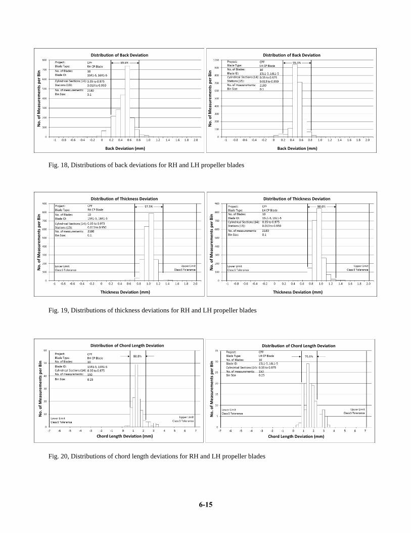
Deviations between measured coordinates and target
coordinates in the regions of leading and trailing
edges were computed to be ± 0.300 mm (± 0.012
inch). This deviation compares favorably with the
deviations for surface points on the pressure and
suction sides and is considerably better than the ISO
484/1 class S tolerance which is: ± 0.5 mm (± 0.020
inch).
All surface points are accurate to ± 0.012 inch for a
total sample of 4360 measured points. Given the
accuracy of all surface points we are confident that
extreme radius, skew and rake were well within ISO
484/1 class S tolerances.
Fig. 17, Distributions of face deviations for RH and LH propeller blades
6-14
Page 15 of 18
Fig. 18, Distributions of back deviations for RH and LH propeller blades
Fig. 19, Distributions of thickness deviations for RH and LH propeller blades
Fig. 20, Distributions of chord length deviations for RH and LH propeller blades
6-15
Page 16 of 18
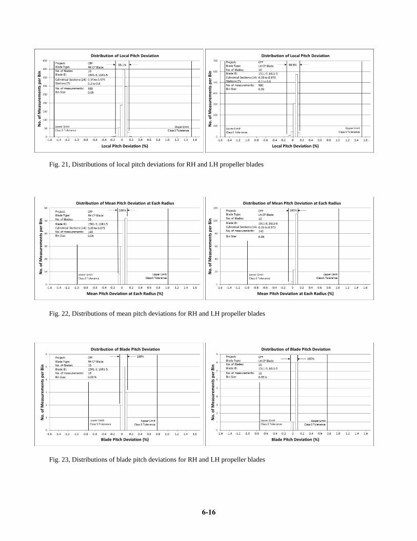
Fig. 21, Distributions of local pitch deviations for RH and LH propeller blades
Fig. 22, Distributions of mean pitch deviations for RH and LH propeller blades
Fig. 23, Distributions of blade pitch deviations for RH and LH propeller blades
6-16
Page 17 of 18
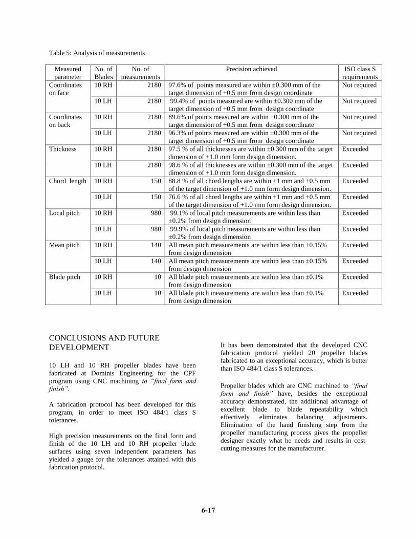
Table 5: Analysis of measurements
Measured
parameter
No. of
Blades
No. of
measurements
Precision achieved ISO class S
requirements
Coordinates
on face
10 RH 2180 97.6% of points measured are within ±0.300 mm of the
target dimension of +0.5 mm from design coordinate
Not required
10 LH 2180 99.4% of points measured are within ±0.300 mm of the
target dimension of +0.5 mm from design coordinate
Not required
Coordinates
on back
10 RH 2180 89.6% of points measured are within ±0.300 mm of the
target dimension of +0.5 mm from design coordinate
Not required
10 LH 2180 96.3% of points measured are within ±0.300 mm of the
target dimension of +0.5 mm from design coordinate
Not required
Thickness 10 RH 2180 97.5 % of all thicknesses are within ±0.300 mm of the target
dimension of +1.0 mm form design dimension.
Exceeded
10 LH 2180 98.6 % of all thicknesses are within ±0.300 mm of the target
dimension of +1.0 mm form design dimension.
Exceeded
Chord length 10 RH 150 88.8 % of all chord lengths are within +1 mm and +0.5 mm
of the target dimension of +1.0 mm form design dimension.
Exceeded
10 LH 150 76.6 % of all chord lengths are within +1 mm and +0.5 mm
of the target dimension of +1.0 mm form design dimension.
Exceeded
Local pitch 10 RH 980 99.1% of local pitch measurements are within less than
±0.2% from design dimension
Exceeded
10 LH 980 99.9% of local pitch measurements are within less than
±0.2% from design dimension
Exceeded
Mean pitch 10 RH 140 All mean pitch measurements are within less than ±0.15%
from design dimension
Exceeded
10 LH 140 All mean pitch measurements are within less than ±0.15%
from design dimension
Exceeded
Blade pitch
10 RH 10 All blade pitch measurements are within less than ±0.1%
from design dimension
Exceeded
10 LH 10 All blade pitch measurements are within less than ±0.1%
from design dimension
Exceeded
CONCLUSIONS AND FUTURE
DEVELOPMENT
10 LH and 10 RH propeller blades have been
fabricated at Dominis Engineering for the CPF
program using CNC machining to “final form and
finish”.
A fabrication protocol has been developed for this
program, in order to meet ISO 484/1 class S
tolerances.
High precision measurements on the final form and
finish of the 10 LH and 10 RH propeller blade
surfaces using seven independent parameters has
yielded a gauge for the tolerances attained with this
fabrication protocol.
It has been demonstrated that the developed CNC
fabrication protocol yielded 20 propeller blades
fabricated to an exceptional accuracy, which is better
than ISO 484/1 class S tolerances.
Propeller blades which are CNC machined to “final
form and finish” have, besides the exceptional
accuracy demonstrated, the additional advantage of
excellent blade to blade repeatability which
effectively eliminates balancing adjustments.
Elimination of the hand finishing step from the
propeller manufacturing process gives the propeller
designer exactly what he needs and results in cost-
cutting measures for the manufacturer.
6-17
Page 18 of 18
Future development efforts are directed towards
speeding up the process of clean-up and smoothing of
input propeller blade data and reducing rough and
finish milling times by developing new tooling for
high speed milling.
ACKNOWLEDGEMENT
I would like to acknowledge the encouragement,
guidance and generous support in developing this
propeller manufacturing process received from the
late Dr. Drasko Gospodnetic, Researcher Emeritus of
the National Research Council of Canada.
REFERENCES:
1) Ridley, Donald E.: “New NC blade
machining facility”; SNAME New England
Section Meeting, April 1982.
2) Nittel, Mark F.: “Numerically Controlled
Machining at Bird-Johnson Company – An
update”; SNAME New England Section
Meeting October 1988.
3) ISO 484/1 – 1981 (E): Shipbuilding – Ship
screw propellers – Manufacturing tolerances
– Part 1: Propellers of diameter greater than
2.5 m, 1981.
4) ISO 484/2 – 1981 (E): Shipbuilding – Ship
screw propellers – Manufacturing tolerances
– Part 2: Propellers of diameter between 0.80
and 2.5 m, 1981
5) Qu, Jun and Shih, Albert J.: “Analytical
surface roughness parameters of a theoretical
profile consisting of elliptical arcs”;
Machining science and technology, Vol. 7,
No. 2, pp. 281-294, Marcel Dekker Inc. 2003
6) Gospodnetic, D. and Gospodnetic S.:
“Integrated propeller manufacturing system”;
Shipbuilding symposium “Sorta”, Zagreb,
May 1996.
7) Gospodnetic, S.: “CNC milling of
monoblock propellers to final form and
finish”, Ottawa Marine Technical
Symposium, Ottawa, February 2013.
6-18