VIESMANN VITODENS 200-W - Viessmann · VIESMANN VITODENS 200-W Gas condensing boiler 12.0 to 150.0...
80
VIESMANN VITODENS 200-W Gas condensing boiler 12.0 to 150.0 kW As multi boiler system up to 900.0 kW VITODENS 200-W Type B2HA Wall mounted gas condensing boiler With modulating MatriX cylinder burner for natural gas and LPG For open flue or room sealed operation 5822 432 GB 4/2014 Technical guide
-
Upload
phunghuong -
Category
Documents
-
view
223 -
download
0
Transcript of VIESMANN VITODENS 200-W - Viessmann · VIESMANN VITODENS 200-W Gas condensing boiler 12.0 to 150.0...
VIESMANN VITODENS 200-WGas condensing boiler
12.0 to 150.0 kWAs multi boiler system up to 900.0 kW
VITODENS 200-W Type B2HA
Wall mounted gas condensing boilerWith modulating MatriX cylinder burner for natural gas andLPGFor open flue or room sealed operation
5822 432 GB 4/2014
Technical guide
Index
1. Vitodens 200-W 1.1 Product description ....................................................................................................... 41.2 Specification ................................................................................................................. 7
■ Vitodens 200-W, 45 and 60 kW ................................................................................ 8■ Vitodens 200-W, 80 and 100 kW .............................................................................. 12■ Vitodens 200-W, 125 and 150 kW ............................................................................ 14
2. Installation accessories 2.1 Product description ....................................................................................................... 17■ Installation accessories for the Vitodens 200-W, 45 and 60 kW ............................... 17■ Installation accessories for the Vitodens 200-W, 80 and 100 kW ............................. 18■ Installation accessories for the Vitodens 200-W, 125 and 150 kW ........................... 18■ Divicon heating circuit distributor .............................................................................. 20■ Installation accessories for multi boiler systems ....................................................... 26
3. DHW cylinder 3.1 Product description ....................................................................................................... 28
4. Design information 4.1 Positioning, installation ................................................................................................. 28■ Siting conditions for open flue operation (appliance type B) ..................................... 28■ Installation conditions for room sealed operation (appliance type C) ....................... 29■ Operation of the Vitodens in wet areas ..................................................................... 29■ Electrical connection ................................................................................................. 29■ Gas connection ......................................................................................................... 30■ Minimum clearances ................................................................................................. 31■ Installing the Vitodens 200-W, 45 to 100 kW directly onto a wall (single boiler) ....... 31■ Installing the Vitodens 200-W, 125 to 150 kW directly onto a wall (single boiler) ..... 32■ Pre-installation, multi boiler system .......................................................................... 34
4.2 Condensate connection ................................................................................................ 43■ Condensate drain and neutralisation ........................................................................ 44
4.3 Hydraulic connection .................................................................................................... 46■ General information .................................................................................................. 46■ Expansion vessels .................................................................................................... 47■ Multi boiler systems .................................................................................................. 47■ Low loss header ........................................................................................................ 47
4.4 Intended use ................................................................................................................. 48
5. Control units 5.1 Vitotronic 100, type HC1B, for constant temperature operation ................................... 49■ Layout and functions ................................................................................................. 49■ Specification Vitotronic 100, type HC1B ................................................................... 49
5.2 Vitotronic 200, type HO1B, for weather-compensated operation ................................. 50■ Specification Vitotronic 200, type HO1B ................................................................... 52
5.3 Vitotronic 300-K, type MW2B for multi boiler systems .................................................. 52■ Cascade control unit for the Vitodens 200-W with a Vitotronic 100 .......................... 52■ Design and function .................................................................................................. 52■ Specification, Vitotronic 300-K .................................................................................. 54■ Delivered condition Vitotronic 300-K ......................................................................... 55
Index
2 VIESMANN VITODENS 200-W
5822
432
GB
5.4 Accessories for the Vitotronic ....................................................................................... 55■ Allocation to control unit types .................................................................................. 55■ Vitotrol 100, type UTA ............................................................................................... 56■ Vitotrol 100, type UTDB ............................................................................................ 56■ External extension H4 ............................................................................................... 57■ Vitotrol 100, type UTDB-RF ...................................................................................... 57■ Notes regarding room temperature hook-up (RS function) for remote control units . 58■ Information on the Vitotrol 200A and Vitotrol 300A ................................................... 58■ Vitotrol 200A ............................................................................................................. 58■ Vitotrol 300A ............................................................................................................. 59■ Information on the Vitotrol 200 RF and Vitotrol 300 RF ............................................ 59■ Vitotrol 200 RF .......................................................................................................... 60■ Vitotrol 300 RF with table-top dock ........................................................................... 60■ Vitotrol 300 RF with wall mounting bracket ............................................................... 61■ Vitocomfort 200 ......................................................................................................... 62■ Wireless base station ................................................................................................ 62■ Wireless outside temperature sensor ....................................................................... 62■ Wireless repeater ...................................................................................................... 63■ Room temperature sensor ........................................................................................ 63■ Immersion temperature sensor ................................................................................. 64■ Mounting base for programming unit ........................................................................ 64■ Radio clock receiver .................................................................................................. 64■ KM BUS distributor ................................................................................................... 64■ Mixer extension kit with integral mixer motor ............................................................ 65■ Mixer extension kit for separate mixer motor ............................................................ 65■ Vitotronic 300-K extension for heating circuits 2 and 3 with mixers .......................... 66■ Extension kit for one heating circuit with mixer in conjunction with Divicon heating
circuit distributor ........................................................................................................ 66■ Extension kit for one heating circuit with mixer for the Vitotronic 300-K ................... 66■ Immersion temperature controller ............................................................................. 67■ Contact temperature controller ................................................................................. 67■ Solar control module, type SM1 ................................................................................ 68■ Internal extension H1 ................................................................................................ 69■ Internal extension H2 ................................................................................................ 69■ AM1 extension .......................................................................................................... 69■ EA1 extension ........................................................................................................... 70■ Vitocom 100, type LAN1 ........................................................................................... 70■ Vitocom 100, type GSM2 .......................................................................................... 71■ Vitocom 200, type LAN2 ........................................................................................... 72■ Vitocom 300, type LAN3 ........................................................................................... 73■ LON connecting cable for data exchange between control units .............................. 75■ Extension of the connecting cable ............................................................................ 76■ Terminator (2 pce) .................................................................................................... 76■ LON communication module ..................................................................................... 76
6. Appendix 6.1 Regulations / Directives ................................................................................................ 76■ Regulations and Directives ....................................................................................... 76
7. Keyword index .............................................................................................................................................. 78
Index (cont.)
VITODENS 200-W VIESMANN 3
5822
432
GB
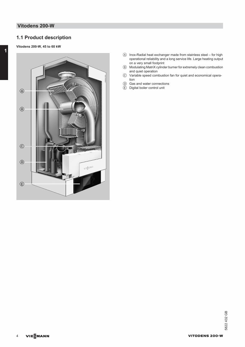
1.1 Product descriptionVitodens 200-W, 45 to 60 kW
A Inox-Radial heat exchanger made from stainless steel – for highoperational reliability and a long service life. Large heating outputon a very small footprint
B Modulating MatriX cylinder burner for extremely clean combustionand quiet operation
C Variable speed combustion fan for quiet and economical opera-tion
D Gas and water connectionsE Digital boiler control unit
Vitodens 200-W
4 VIESMANN VITODENS 200-W
1
5822
432
GB
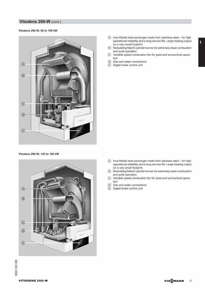
Vitodens 200-W, 80 to 100 kW
A Inox-Radial heat exchanger made from stainless steel – for highoperational reliability and a long service life. Large heating outputon a very small footprint
B Modulating MatriX cylinder burner for extremely clean combustionand quiet operation
C Variable speed combustion fan for quiet and economical opera-tion
D Gas and water connectionsE Digital boiler control unit
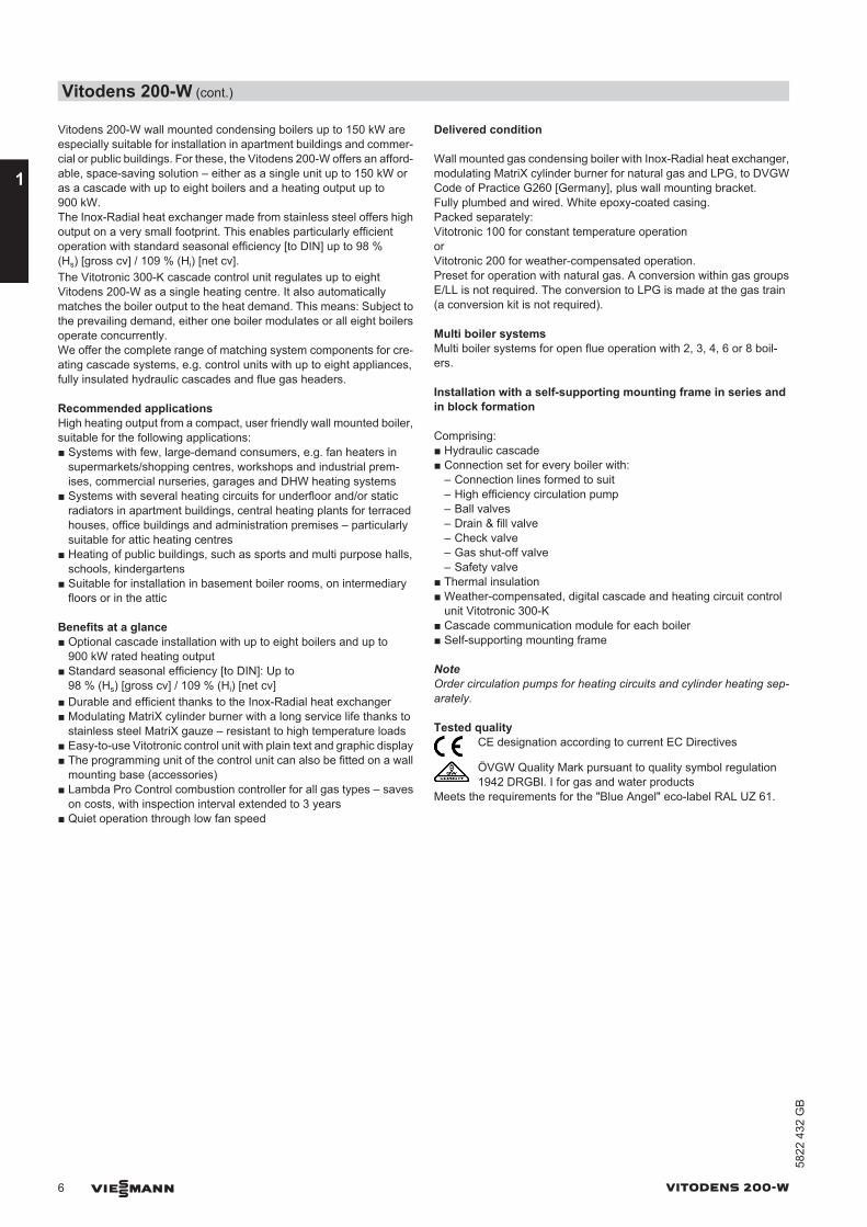
Vitodens 200-W, 125 to 150 kW
A Inox-Radial heat exchanger made from stainless steel – for highoperational reliability and a long service life. Large heating outputon a very small footprint.
B Modulating MatriX cylinder burner for extremely clean combustionand quiet operation
C Variable speed combustion fan for quiet and economical opera-tion
D Gas and water connectionsE Digital boiler control unit
Vitodens 200-W (cont.)
VITODENS 200-W VIESMANN 5
5822
432
GB
1
Vitodens 200-W wall mounted condensing boilers up to 150 kW areespecially suitable for installation in apartment buildings and commer-cial or public buildings. For these, the Vitodens 200-W offers an afford-able, space-saving solution – either as a single unit up to 150 kW oras a cascade with up to eight boilers and a heating output up to900 kW.The Inox-Radial heat exchanger made from stainless steel offers highoutput on a very small footprint. This enables particularly efficientoperation with standard seasonal efficiency [to DIN] up to 98 %(Hs) [gross cv] / 109 % (Hi) [net cv].The Vitotronic 300-K cascade control unit regulates up to eightVitodens 200-W as a single heating centre. It also automaticallymatches the boiler output to the heat demand. This means: Subject tothe prevailing demand, either one boiler modulates or all eight boilersoperate concurrently.We offer the complete range of matching system components for cre-ating cascade systems, e.g. control units with up to eight appliances,fully insulated hydraulic cascades and flue gas headers.
Recommended applicationsHigh heating output from a compact, user friendly wall mounted boiler,suitable for the following applications:■ Systems with few, large-demand consumers, e.g. fan heaters in
supermarkets/shopping centres, workshops and industrial prem-ises, commercial nurseries, garages and DHW heating systems
■ Systems with several heating circuits for underfloor and/or staticradiators in apartment buildings, central heating plants for terracedhouses, office buildings and administration premises – particularlysuitable for attic heating centres
■ Heating of public buildings, such as sports and multi purpose halls,schools, kindergartens
■ Suitable for installation in basement boiler rooms, on intermediaryfloors or in the attic
Benefits at a glance■ Optional cascade installation with up to eight boilers and up to
900 kW rated heating output■ Standard seasonal efficiency [to DIN]: Up to
98 % (Hs) [gross cv] / 109 % (Hi) [net cv]■ Durable and efficient thanks to the Inox-Radial heat exchanger■ Modulating MatriX cylinder burner with a long service life thanks to
stainless steel MatriX gauze – resistant to high temperature loads■ Easy-to-use Vitotronic control unit with plain text and graphic display■ The programming unit of the control unit can also be fitted on a wall
mounting base (accessories)■ Lambda Pro Control combustion controller for all gas types – saves
on costs, with inspection interval extended to 3 years■ Quiet operation through low fan speed
Delivered condition
Wall mounted gas condensing boiler with Inox-Radial heat exchanger,modulating MatriX cylinder burner for natural gas and LPG, to DVGWCode of Practice G260 [Germany], plus wall mounting bracket.Fully plumbed and wired. White epoxy-coated casing.Packed separately:Vitotronic 100 for constant temperature operationorVitotronic 200 for weather-compensated operation.Preset for operation with natural gas. A conversion within gas groupsE/LL is not required. The conversion to LPG is made at the gas train(a conversion kit is not required).
Multi boiler systemsMulti boiler systems for open flue operation with 2, 3, 4, 6 or 8 boil-ers.
Installation with a self-supporting mounting frame in series andin block formation
Comprising:■ Hydraulic cascade■ Connection set for every boiler with:
– Connection lines formed to suit– High efficiency circulation pump– Ball valves– Drain & fill valve– Check valve– Gas shut-off valve– Safety valve
■ Thermal insulation■ Weather-compensated, digital cascade and heating circuit control
unit Vitotronic 300-K■ Cascade communication module for each boiler■ Self-supporting mounting frame
NoteOrder circulation pumps for heating circuits and cylinder heating sep-arately.
Tested qualityCE designation according to current EC Directives
ÖVGW Quality Mark pursuant to quality symbol regulation1942 DRGBl. I for gas and water products
Meets the requirements for the "Blue Angel" eco-label RAL UZ 61.
Vitodens 200-W (cont.)
6 VIESMANN VITODENS 200-W
1
5822
432
GB
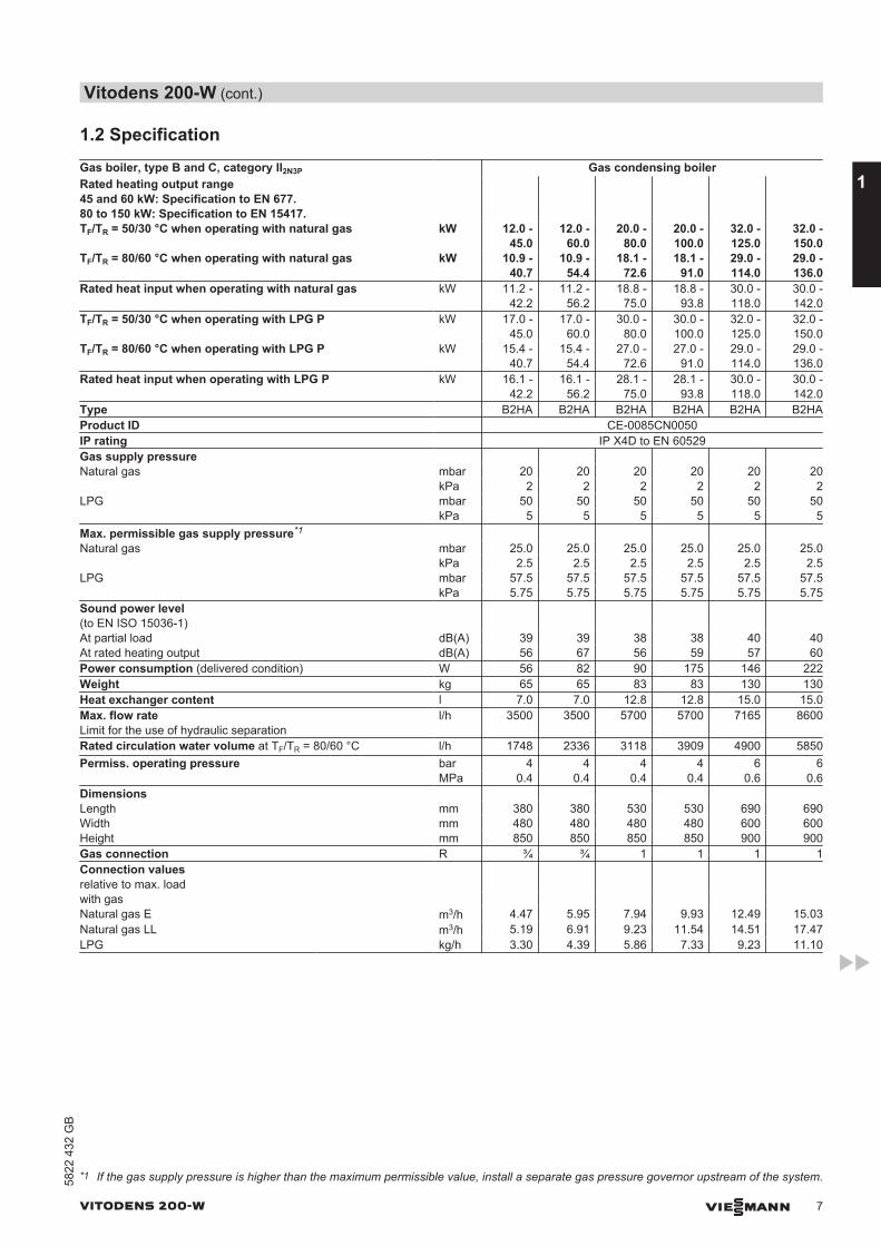
1.2 SpecificationGas boiler, type B and C, category II2N3P Gas condensing boilerRated heating output range45 and 60 kW: Specification to EN 677. 80 to 150 kW: Specification to EN 15417.
TF/TR = 50/30 °C when operating with natural gas kW 12.0 -45.0
12.0 -60.0
20.0 -80.0
20.0 -100.0
32.0 -125.0
32.0 -150.0
TF/TR = 80/60 °C when operating with natural gas kW 10.9 -40.7
10.9 -54.4
18.1 -72.6
18.1 -91.0
29.0 -114.0
29.0 -136.0
Rated heat input when operating with natural gas kW 11.2 -42.2
11.2 -56.2
18.8 -75.0
18.8 -93.8
30.0 -118.0
30.0 -142.0
TF/TR = 50/30 °C when operating with LPG P kW 17.0 -45.0
17.0 -60.0
30.0 -80.0
30.0 -100.0
32.0 -125.0
32.0 -150.0
TF/TR = 80/60 °C when operating with LPG P kW 15.4 -40.7
15.4 -54.4
27.0 -72.6
27.0 -91.0
29.0 -114.0
29.0 -136.0
Rated heat input when operating with LPG P kW 16.1 -42.2
16.1 -56.2
28.1 -75.0
28.1 -93.8
30.0 -118.0
30.0 -142.0
Type B2HA B2HA B2HA B2HA B2HA B2HAProduct ID CE-0085CN0050IP rating IP X4D to EN 60529Gas supply pressure Natural gas mbar 20 20 20 20 20 20 kPa 2 2 2 2 2 2LPG mbar 50 50 50 50 50 50 kPa 5 5 5 5 5 5Max. permissible gas supply pressure*1 Natural gas mbar 25.0 25.0 25.0 25.0 25.0 25.0 kPa 2.5 2.5 2.5 2.5 2.5 2.5LPG mbar 57.5 57.5 57.5 57.5 57.5 57.5 kPa 5.75 5.75 5.75 5.75 5.75 5.75Sound power level(to EN ISO 15036-1)
At partial load dB(A) 39 39 38 38 40 40At rated heating output dB(A) 56 67 56 59 57 60Power consumption (delivered condition) W 56 82 90 175 146 222Weight kg 65 65 83 83 130 130Heat exchanger content l 7.0 7.0 12.8 12.8 15.0 15.0Max. flow rateLimit for the use of hydraulic separation
l/h 3500 3500 5700 5700 7165 8600
Rated circulation water volume at TF/TR = 80/60 °C l/h 1748 2336 3118 3909 4900 5850Permiss. operating pressure bar 4 4 4 4 6 6 MPa 0.4 0.4 0.4 0.4 0.6 0.6Dimensions Length mm 380 380 530 530 690 690Width mm 480 480 480 480 600 600Height mm 850 850 850 850 900 900Gas connection R ¾ ¾ 1 1 1 1Connection valuesrelative to max. load
with gas Natural gas E m3/h 4.47 5.95 7.94 9.93 12.49 15.03Natural gas LL m3/h 5.19 6.91 9.23 11.54 14.51 17.47LPG kg/h 3.30 4.39 5.86 7.33 9.23 11.10
*1 If the gas supply pressure is higher than the maximum permissible value, install a separate gas pressure governor upstream of the system.
Vitodens 200-W (cont.)
VITODENS 200-W VIESMANN 7
5822
432
GB
1
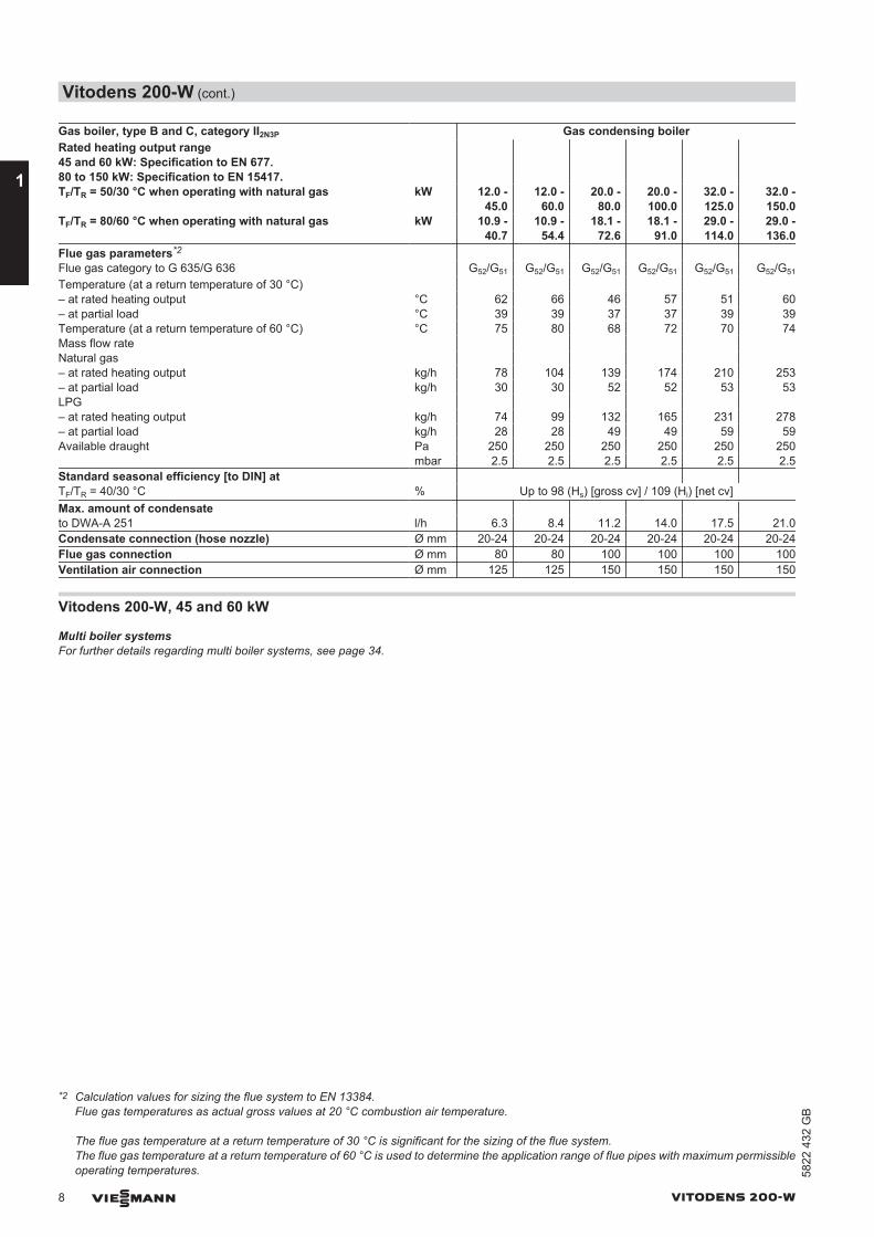
Gas boiler, type B and C, category II2N3P Gas condensing boilerRated heating output range45 and 60 kW: Specification to EN 677. 80 to 150 kW: Specification to EN 15417.
TF/TR = 50/30 °C when operating with natural gas kW 12.0 -45.0
12.0 -60.0
20.0 -80.0
20.0 -100.0
32.0 -125.0
32.0 -150.0
TF/TR = 80/60 °C when operating with natural gas kW 10.9 -40.7
10.9 -54.4
18.1 -72.6
18.1 -91.0
29.0 -114.0
29.0 -136.0
Flue gas parameters*2 Flue gas category to G 635/G 636 G52/G51 G52/G51 G52/G51 G52/G51 G52/G51 G52/G51
Temperature (at a return temperature of 30 °C) – at rated heating output °C 62 66 46 57 51 60– at partial load °C 39 39 37 37 39 39Temperature (at a return temperature of 60 °C) °C 75 80 68 72 70 74Mass flow rate Natural gas – at rated heating output kg/h 78 104 139 174 210 253– at partial load kg/h 30 30 52 52 53 53LPG – at rated heating output kg/h 74 99 132 165 231 278– at partial load kg/h 28 28 49 49 59 59Available draught Pa 250 250 250 250 250 250 mbar 2.5 2.5 2.5 2.5 2.5 2.5Standard seasonal efficiency [to DIN] at TF/TR = 40/30 °C % Up to 98 (Hs) [gross cv] / 109 (Hi) [net cv]Max. amount of condensate to DWA-A 251 l/h 6.3 8.4 11.2 14.0 17.5 21.0Condensate connection (hose nozzle) Ø mm 20-24 20-24 20-24 20-24 20-24 20-24Flue gas connection Ø mm 80 80 100 100 100 100Ventilation air connection Ø mm 125 125 150 150 150 150
Vitodens 200-W, 45 and 60 kW
Multi boiler systemsFor further details regarding multi boiler systems, see page 34.
*2 Calculation values for sizing the flue system to EN 13384.Flue gas temperatures as actual gross values at 20 °C combustion air temperature.
The flue gas temperature at a return temperature of 30 °C is significant for the sizing of the flue system.The flue gas temperature at a return temperature of 60 °C is used to determine the application range of flue pipes with maximum permissibleoperating temperatures.
Vitodens 200-W (cont.)
8 VIESMANN VITODENS 200-W
1
5822
432
GB
40
100
160 160
752
1975
1690
850
380
480
875
1166
160
EA
L
M
O
CB D F
H
PK
N
200
G
65 65
R
902
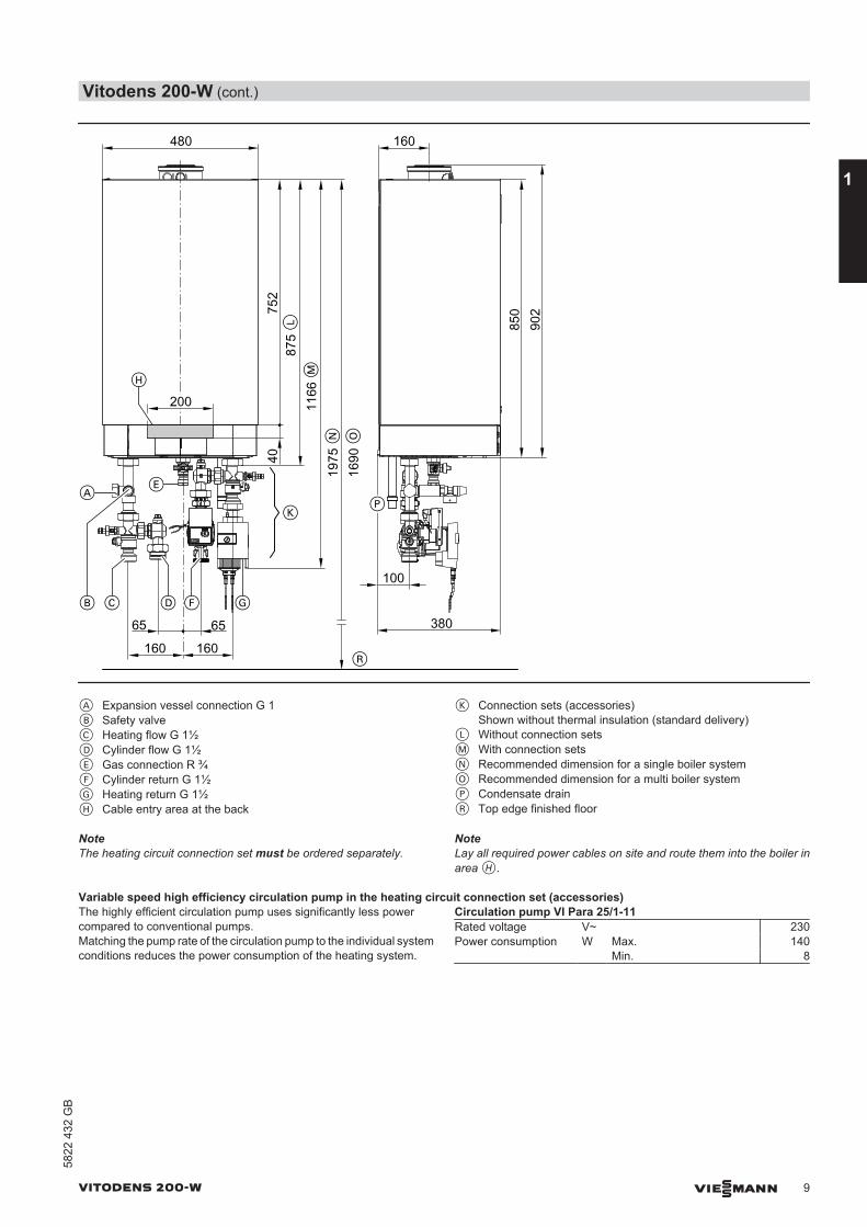
A Expansion vessel connection G 1B Safety valveC Heating flow G 1½D Cylinder flow G 1½E Gas connection R ¾F Cylinder return G 1½G Heating return G 1½H Cable entry area at the back
K Connection sets (accessories)Shown without thermal insulation (standard delivery)
L Without connection setsM With connection setsN Recommended dimension for a single boiler system O Recommended dimension for a multi boiler systemP Condensate drainR Top edge finished floor
NoteThe heating circuit connection set must be ordered separately.
NoteLay all required power cables on site and route them into the boiler inarea H.
Variable speed high efficiency circulation pump in the heating circuit connection set (accessories)The highly efficient circulation pump uses significantly less powercompared to conventional pumps.Matching the pump rate of the circulation pump to the individual systemconditions reduces the power consumption of the heating system.
Circulation pump VI Para 25/1-11Rated voltage V~ 230Power consumption W Max. 140 Min. 8
Vitodens 200-W (cont.)
VITODENS 200-W VIESMANN 9
5822
432
GB
1
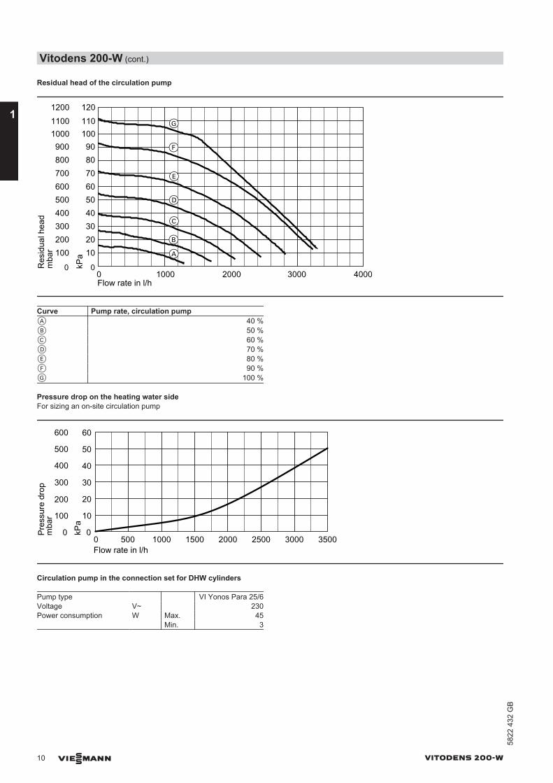
Residual head of the circulation pump
100
00 1000Flow rate in l/h
200
600
800
1000
300400500
700
900
2000 3000 4000
10
0
20
60
80
100
304050
70
90
kPa
1100 1101200 120
A
B
C
D
E
F
G
Res
idua
l hea
dm
bar
Curve Pump rate, circulation pumpA 40 %B 50 %C 60 %D 70 %E 80 %F 90 %G 100 %
Pressure drop on the heating water sideFor sizing an on-site circulation pump
0 500 1000 15000
100
200
300
400
500
600
Pres
sure
dro
p
0
10
20
30
40
50
60
kPa
2000 2500 3000 3500Flow rate in l/h
mba
r
Circulation pump in the connection set for DHW cylinders
Pump type VI Yonos Para 25/6Voltage V~ 230Power consumption W Max. 45
Min. 3
Vitodens 200-W (cont.)
10 VIESMANN VITODENS 200-W
1
5822
432
GB
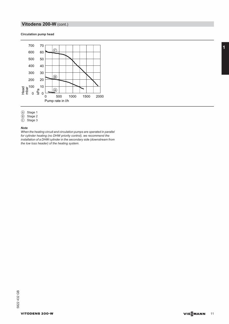
Circulation pump head
0 500 1000 15000
100
200
300
400
500
600
Hea
d
0
10
20
30
40
50
60
kPa
2000Pump rate in l/h
A
B
700 70C
mba
r
A Stage 1B Stage 2C Stage 3
NoteWhen the heating circuit and circulation pumps are operated in parallelfor cylinder heating (no DHW priority control), we recommend theinstallation of a DHW cylinder in the secondary side (downstream fromthe low loss header) of the heating system.
Vitodens 200-W (cont.)
VITODENS 200-W VIESMANN 11
5822
432
GB
1
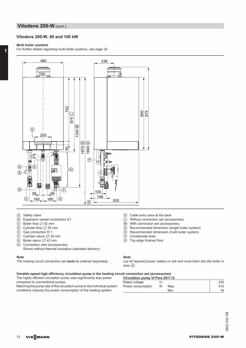
Vitodens 200-W, 80 and 100 kW
Multi boiler systemsFor further details regarding multi boiler systems, see page 34.
100
850
530
P
40
160 160
200
752
1975
1690
480
875
1300
E
L
M
O
K
H
N
236
A
B
C G
D F56 56
975
146R
A Safety valveB Expansion vessel connection G1C Boiler flow 7 42 mmD Cylinder flow 7 35 mmE Gas connection R 1F Cylinder return 7 35 mmG Boiler return 7 42 mmH Connection sets (accessories)
Shown without thermal insulation (standard delivery)
K Cable entry area at the backL Without connection set (accessories)M With connection set (accessories)N Recommended dimension (single boiler system)O Recommended dimension (multi boiler system)P Condensate drainR Top edge finished floor
NoteThe heating circuit connection set must be ordered separately.
NoteLay all required power cables on site and route them into the boiler inarea K.
Variable speed high efficiency circulation pump in the heating circuit connection set (accessories)The highly efficient circulation pump uses significantly less powercompared to conventional pumps.Matching the pump rate of the circulation pump to the individual systemconditions reduces the power consumption of the heating system.
Circulation pump VI Para 25/1-12Rated voltage V~ 230Power consumption W Max. 310 Min. 16
Vitodens 200-W (cont.)
12 VIESMANN VITODENS 200-W
1
5822
432
GB
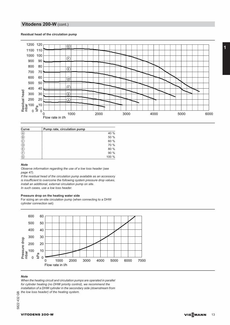
Residual head of the circulation pump
100
00 1000Flow rate in l/h
200
600
800
1000
300400500
700
900
2000 3000 4000
10
0
20
60
80
100
304050
70
90
kPa
5000 6000
1100 1101200 120
A
B
C
D
E
F
G
Res
idua
l hea
dm
bar
Curve Pump rate, circulation pumpA 40 %B 50 %C 60 %D 70 %E 80 %F 90 %G 100 %
NoteObserve information regarding the use of a low loss header (seepage 47).If the residual head of the circulation pump available as an accessoryis insufficient to overcome the following system pressure drop values,install an additional, external circulation pump on site.In such cases, use a low loss header.
Pressure drop on the heating water sideFor sizing an on-site circulation pump (when connecting to a DHWcylinder connection set)
0 1000 2000 30000
100
200
300
400
500
600
Pres
sure
dro
p
0
10
20
30
40
50
60
kPa
4000 5000 6000 7000Flow rate in l/h
mba
r
NoteWhen the heating circuit and circulation pumps are operated in parallelfor cylinder heating (no DHW priority control), we recommend theinstallation of a DHW cylinder in the secondary side (downstream fromthe low loss header) of the heating system.
Vitodens 200-W (cont.)
VITODENS 200-W VIESMANN 13
5822
432
GB
1
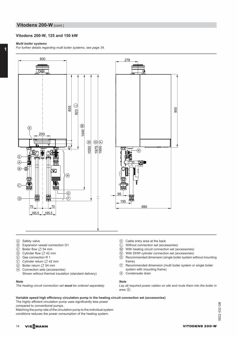
Vitodens 200-W, 125 and 150 kW
Multi boiler systemsFor further details regarding multi boiler systems, see page 34.
165,5165,5
923
1440
95
690
278
900
600
40
200
855
1975
1950
E
L
M
P
K
H
O
A
B
C
G
D F
70 70195
R1550N
A Safety valveB Expansion vessel connection G1C Boiler flow 7 54 mmD Cylinder flow 7 42 mmE Gas connection R 1F Cylinder return 7 42 mmG Boiler return 7 54 mmH Connection sets (accessories)
Shown without thermal insulation (standard delivery)
K Cable entry area at the backL Without connection set (accessories)M With heating circuit connection set (accessories)N With DHW cylinder connection set (accessories)O Recommended dimension (single boiler system without mounting
frame)P Recommended dimension (multi boiler system or single boiler
system with mounting frame)R Condensate drain
NoteThe heating circuit connection set must be ordered separately.
NoteLay all required power cables on site and route them into the boiler inarea K.
Variable speed high efficiency circulation pump in the heating circuit connection set (accessories)The highly efficient circulation pump uses significantly less powercompared to conventional pumps.Matching the pump rate of the circulation pump to the individual systemconditions reduces the power consumption of the heating system.
Vitodens 200-W (cont.)
14 VIESMANN VITODENS 200-W
1
5822
432
GB
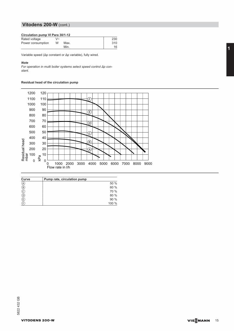
Circulation pump VI Para 30/1-12Rated voltage V~ 230Power consumption W Max. 310 Min. 16
Variable speed (Δp constant or Δp variable), fully wired.
NoteFor operation in multi boiler systems select speed control Δp con-stant.
Residual head of the circulation pump
100
00 2000Flow rate in l/h
200
600
800
1000
300400500
700
900
10
0
20
60
80
100
304050
70
90
kPa
1100 1101200 120
1000 40003000 60005000 80007000 9000
F
E
D
C
B
A
Res
idua
l hea
dm
bar
Curve Pump rate, circulation pumpA 50 %B 60 %C 70 %D 80 %E 90 %F 100 %
Vitodens 200-W (cont.)
VITODENS 200-W VIESMANN 15
5822
432
GB
1

NoteObserve information regarding the use of a low loss header (seepage 47).If the residual head of the circulation pump available as an accessoryis insufficient to overcome the following system pressure drop values,install an additional, external circulation pump on site.In such cases, use a low loss header.
Pressure drop on the heating water sideFor sizing an on-site circulation pump (when connecting to a DHWcylinder connection set)
0 1000 2000 30000
100
200
300
400
500
600
Pres
sure
dro
p
0
10
20
30
40
50
60
kPa
4000 5000 6000 7000Flow rate in l/h
mba
r
NoteWhen the heating circuit and circulation pumps are operated in parallelfor cylinder heating (no DHW priority control), we recommend theinstallation of a DHW cylinder in the secondary side (downstream fromthe low loss header) of the heating system.
Vitodens 200-W (cont.)
16 VIESMANN VITODENS 200-W
1
5822
432
GB
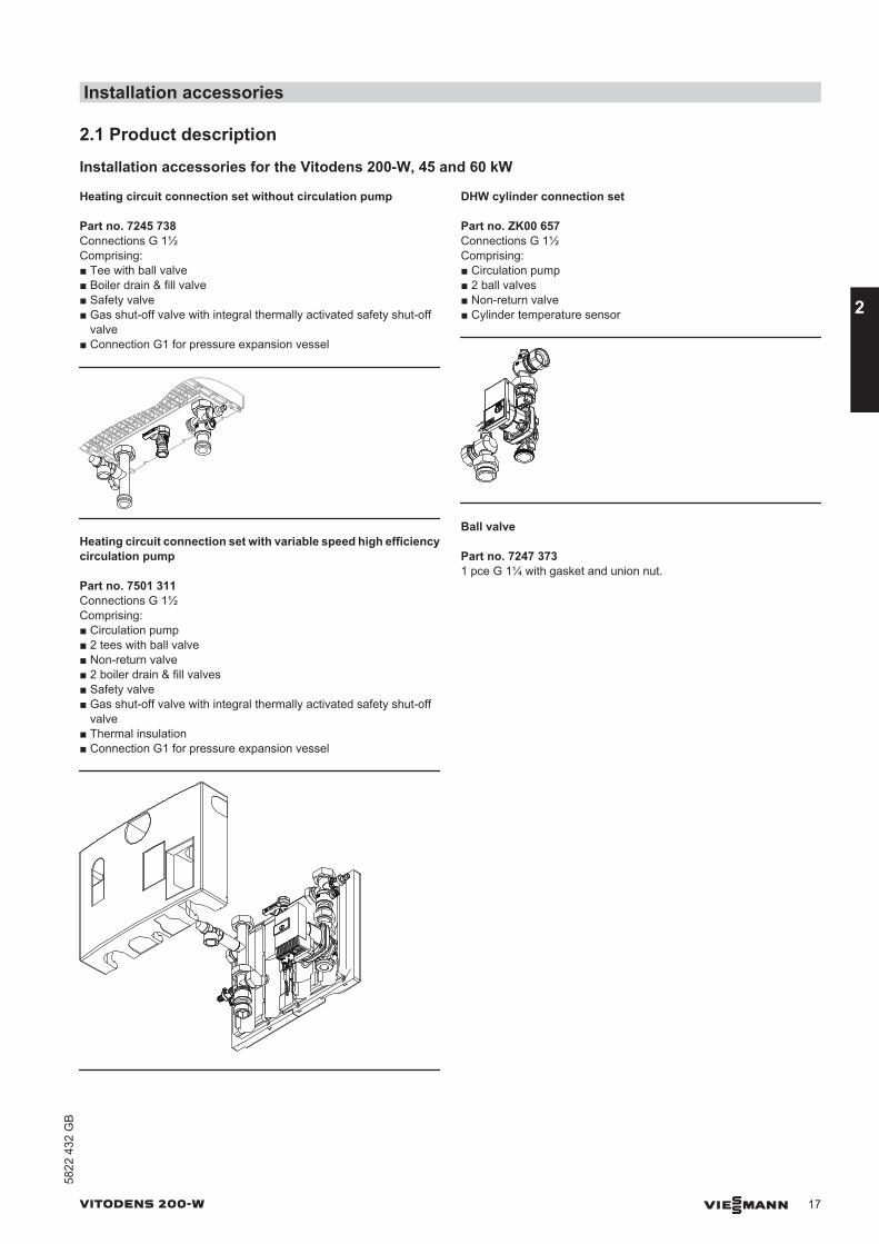
2.1 Product description
Installation accessories for the Vitodens 200-W, 45 and 60 kW
Heating circuit connection set without circulation pump
Part no. 7245 738Connections G 1½Comprising:■ Tee with ball valve■ Boiler drain & fill valve■ Safety valve■ Gas shut-off valve with integral thermally activated safety shut-off
valve■ Connection G1 for pressure expansion vessel
Heating circuit connection set with variable speed high efficiencycirculation pump
Part no. 7501 311Connections G 1½Comprising:■ Circulation pump■ 2 tees with ball valve■ Non-return valve■ 2 boiler drain & fill valves■ Safety valve■ Gas shut-off valve with integral thermally activated safety shut-off
valve■ Thermal insulation■ Connection G1 for pressure expansion vessel
DHW cylinder connection set
Part no. ZK00 657Connections G 1½Comprising:■ Circulation pump■ 2 ball valves■ Non-return valve■ Cylinder temperature sensor
Ball valve
Part no. 7247 3731 pce G 1¼ with gasket and union nut.
Installation accessories
VITODENS 200-W VIESMANN 17
5822
432
GB
2
Installation accessories for the Vitodens 200-W, 80 and 100 kW
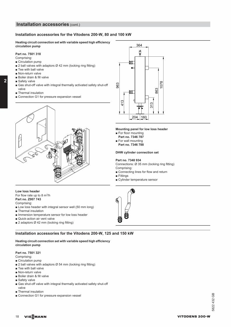
Heating circuit connection set with variable speed high efficiencycirculation pump
Part no. 7501 318Comprising:■ Circulation pump■ 2 ball valves with adaptors Ø 42 mm (locking ring fitting)■ Tee with ball valve■ Non-return valve■ Boiler drain & fill valve■ Safety valve■ Gas shut-off valve with integral thermally activated safety shut-off
valve■ Thermal insulation■ Connection G1 for pressure expansion vessel
Low loss headerFor flow rate up to 8 m3/hPart no. Z007 743Comprising:■ Low loss header with integral sensor well (50 mm long)■ Thermal insulation■ Immersion temperature sensor for low loss header■ Quick-action air vent valve■ 2 adaptors Ø 42 mm (locking ring fitting)
364
16020441
396
3
313
1078
863
Mounting panel for low loss header■ For floor mounting
Part no. 7346 787■ For wall mounting
Part no. 7346 788
DHW cylinder connection set
Part no. 7348 934Connections: Ø 35 mm (locking ring fitting)Comprising:■ Connecting lines for flow and return■ Fittings■ Cylinder temperature sensor
Installation accessories for the Vitodens 200-W, 125 and 150 kW
Heating circuit connection set with variable speed high efficiencycirculation pump
Part no. 7501 321Comprising:■ Circulation pump■ 2 ball valves with adaptors Ø 54 mm (locking ring fitting)■ Tee with ball valve■ Non-return valve■ Boiler drain & fill valve■ Safety valve■ Gas shut-off valve with integral thermally activated safety shut-off
valve■ Thermal insulation■ Connection G1 for pressure expansion vessel
Installation accessories (cont.)
18 VIESMANN VITODENS 200-W
2
5822
432
GB
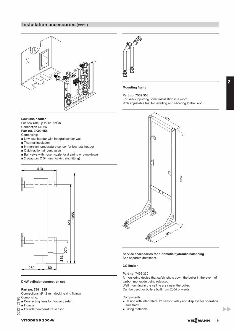
Low loss headerFor flow rate up to 12.9 m3/hConnection DN 65Part no. ZK00 658Comprising:■ Low loss header with integral sensor well■ Thermal insulation■ Immersion temperature sensor for low loss header■ Quick-action air vent valve■ Ball valve with hose nozzle for draining or blow-down■ 2 adaptors Ø 54 mm (locking ring fitting)
410
230 180
115
270
920 10
55
DHW cylinder connection set
Part no. 7501 325Connections: Ø 42 mm (locking ring fitting)Comprising:■ Connecting lines for flow and return■ Fittings■ Cylinder temperature sensor
Mounting frame
Part no. 7502 558For self-supporting boiler installation in a room.With adjustable feet for levelling and securing to the floor.
600
650
1950
Service accessories for automatic hydraulic balancingSee separate datasheet.
CO limiter
Part no. 7499 330A monitoring device that safely shuts down the boiler in the event ofcarbon monoxide being released.Wall mounting in the ceiling area near the boiler.Can be used for boilers built from 2004 onwards.
Components:■ Casing with integrated CO sensor, relay and displays for operation
and alarm.■ Fixing materials.
Installation accessories (cont.)
VITODENS 200-W VIESMANN 19
5822
432
GB
2
■ Power cable (2.0 m long).■ Connecting cable, relay for burner shutdown (2.0 m long).
70 45
117
SpecificationRated voltage 230 V~Rated frequency 50 HzPower consumption 3.5 WRated breaking capacity of the relay out-put
8 A 230 V~
Alarm threshold 40 ppm COSafety category IIIP rating IP 20 to EN 60529; ensure
through design/installationPermissible ambient temperature 70 °C
Divicon heating circuit distributor
Layout and function■ Available with R ¾, R 1 and R 1¼ connections.■ With heating circuit pump, check valve, ball valves with integral ther-
mometers and 3-way mixer or without mixer.■ Quick and simple installation due to pre-assembled unit and com-
pact design.■ All-round thermal insulation shells for low radiation losses.■ High efficiency pumps and optimised mixer curve ensure low elec-
tricity costs and precise control characteristics.■ The bypass valve for hydraulic balancing of the heating system is
available as an accessory and is provided as a threaded componentfor inserting into the prepared hole in the cast body.
■ Individually wall mounted or with a double or triple manifold.■ Also available as a kit. For further details see the Viessmann pricel-
ist.
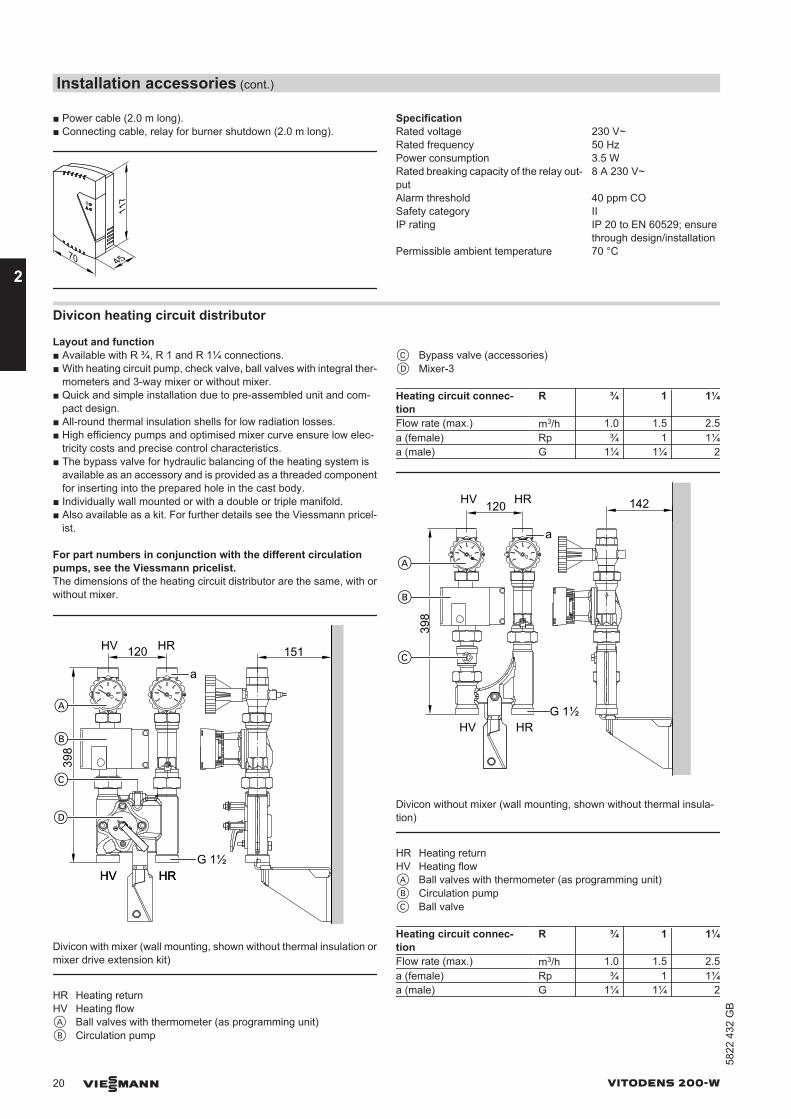
For part numbers in conjunction with the different circulationpumps, see the Viessmann pricelist.The dimensions of the heating circuit distributor are the same, with orwithout mixer.
D
151
398
A
B
C
G 1½
120HV HR
HV HRHV HR
a
Divicon with mixer (wall mounting, shown without thermal insulation ormixer drive extension kit)
HR Heating returnHV Heating flowA Ball valves with thermometer (as programming unit)B Circulation pump
C Bypass valve (accessories)D Mixer-3
Heating circuit connec-tion
R ¾ 1 1¼
Flow rate (max.) m3/h 1.0 1.5 2.5a (female) Rp ¾ 1 1¼a (male) G 1¼ 1¼ 2
142
398
A
B
HV HR120
C
G 1½HV HR
a
Divicon without mixer (wall mounting, shown without thermal insula-tion)
HR Heating returnHV Heating flowA Ball valves with thermometer (as programming unit)B Circulation pumpC Ball valve
Heating circuit connec-tion
R ¾ 1 1¼
Flow rate (max.) m3/h 1.0 1.5 2.5a (female) Rp ¾ 1 1¼a (male) G 1¼ 1¼ 2
Installation accessories (cont.)
20 VIESMANN VITODENS 200-W
2
5822
432
GB
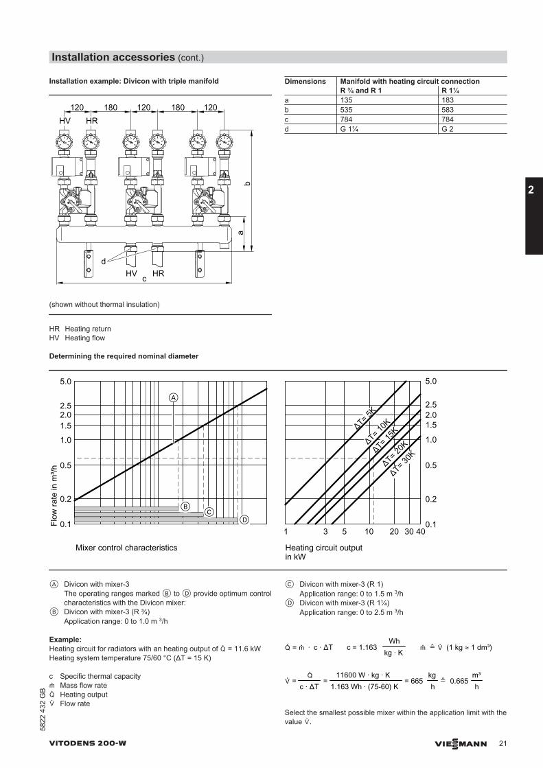
Installation example: Divicon with triple manifold
HV HR120 120 120
ba
d
c
180 180
HV HR
(shown without thermal insulation)
HR Heating returnHV Heating flow
Dimensions Manifold with heating circuit connection R ¾ and R 1 R 1¼a 135 183b 535 583c 784 784d G 1¼ G 2
Determining the required nominal diameter
A
ΔT= 15K
ΔT= 20K
ΔT= 30K
ΔT= 5K
ΔT= 10K
CB
D
2.52.5
Mixer control characteristics
2.0
0.1
0.2
0.5
1.0
1.5
5.0
Flow
rate
in m
³/h
10 20 30 405310.1
0.2
0.5
1.0
1.52.0
5.0
Heating circuit outputin kW
A Divicon with mixer-3The operating ranges marked B to D provide optimum controlcharacteristics with the Divicon mixer:
B Divicon with mixer-3 (R ¾)Application range: 0 to 1.0 m 3/h
C Divicon with mixer-3 (R 1)Application range: 0 to 1.5 m 3/h
D Divicon with mixer-3 (R 1¼)Application range: 0 to 2.5 m 3/h
Example:Heating circuit for radiators with an heating output of ² = 11.6 kWHeating system temperature 75/60 °C (ΔT = 15 K) c Specific thermal capacityµ Mass flow rate² Heating output´ Flow rate
² = µ · c · ΔT c = 1.163Wh
kg · K µ
²
c · ΔT=
kgh
´ =11600 W · kg · K
1.163 Wh · (75-60) K= 665
m³h
0.665
´ (1 kg ≈ 1 dm³)
Select the smallest possible mixer within the application limit with thevalue ´.
Installation accessories (cont.)
VITODENS 200-W VIESMANN 21
5822
432
GB
2
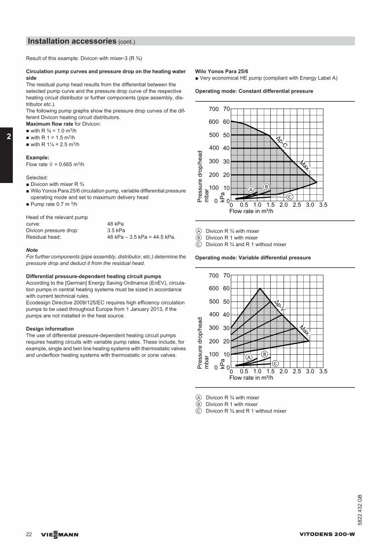
Result of this example: Divicon with mixer-3 (R ¾)
Circulation pump curves and pressure drop on the heating watersideThe residual pump head results from the differential between theselected pump curve and the pressure drop curve of the respectiveheating circuit distributor or further components (pipe assembly, dis-tributor etc.).The following pump graphs show the pressure drop curves of the dif-ferent Divicon heating circuit distributors. Maximum flow rate for Divicon:■ with R ¾ = 1.0 m3/h■ with R 1 = 1.5 m3/h■ with R 1¼ = 2.5 m3/h
Example:Flow rate ´ = 0.665 m3/h
Selected:■ Divicon with mixer R ¾■ Wilo Yonos Para 25/6 circulation pump, variable differential pressure
operating mode and set to maximum delivery head■ Pump rate 0.7 m 3/h
Head of the relevant pumpcurve: 48 kPaDivicon pressure drop: 3.5 kPaResidual head: 48 kPa – 3.5 kPa = 44.5 kPa.
NoteFor further components (pipe assembly, distributor, etc.) determine thepressure drop and deduct it from the residual head.
Differential pressure-dependent heating circuit pumpsAccording to the [German] Energy Saving Ordinance (EnEV), circula-tion pumps in central heating systems must be sized in accordancewith current technical rules. Ecodesign Directive 2009/125/EC requires high efficiency circulationpumps to be used throughout Europe from 1 January 2013, if thepumps are not installed in the heat source.
Design informationThe use of differential pressure-dependent heating circuit pumpsrequires heating circuits with variable pump rates. These include, forexample, single and twin line heating systems with thermostatic valvesand underfloor heating systems with thermostatic or zone valves.
Wilo Yonos Para 25/6■ Very economical HE pump (compliant with Energy Label A)
Operating mode: Constant differential pressure
40
0
10
20
30
0
100
200
300
400
0 0.5 1.0 1.5 2.0 2.5Flow rate in m³/h
Pres
sure
dro
p/he
adm
bar
kPa
50500
60600
3.0 3.5
70700Δp-C
Max.
C
BA
A Divicon R ¾ with mixerB Divicon R 1 with mixerC Divicon R ¾ and R 1 without mixer
Operating mode: Variable differential pressure
40
0
10
20
30
0
100
200
300
400
0 0.5 1.0 1.5 2.0 2.5Flow rate in m³/h
Pres
sure
dro
p/he
adm
bar
kPa
50500
60600
3.0 3.5
70700
Δp-V
Max.
AC
B
A Divicon R ¾ with mixerB Divicon R 1 with mixerC Divicon R ¾ and R 1 without mixer
Installation accessories (cont.)
22 VIESMANN VITODENS 200-W
2
5822
432
GB
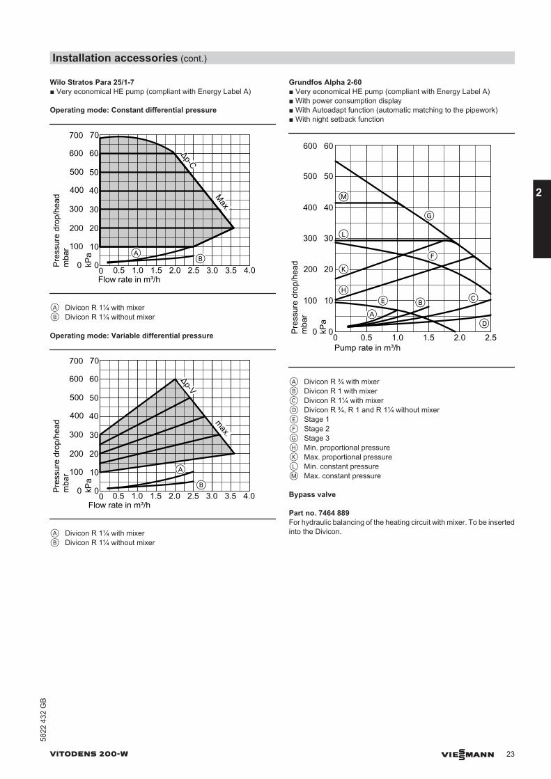
Wilo Stratos Para 25/1-7■ Very economical HE pump (compliant with Energy Label A)
Operating mode: Constant differential pressure
40
0
10
20
30
0
100
200
300
400
0 0.5 1.0 1.5 2.0 2.5Flow rate in m³/h
Pres
sure
dro
p/he
adm
bar
kPa
50500
60600
3.0 3.5 4.0
70700
Δp-C
Max.
BA
A Divicon R 1¼ with mixerB Divicon R 1¼ without mixer
Operating mode: Variable differential pressure
40
0
10
20
30
0
100
200
300
400
0 0.5 1.0 1.5 2.0 2.5Flow rate in m³/h
Pres
sure
dro
p/he
adm
bar
kPa
50500
60600
3.0 3.5 4.0
70700Δp-V
max.
B
A
A Divicon R 1¼ with mixerB Divicon R 1¼ without mixer
Grundfos Alpha 2-60■ Very economical HE pump (compliant with Energy Label A)■ With power consumption display■ With Autoadapt function (automatic matching to the pipework)■ With night setback function
DA
B CE
F
G
H
K
L
M40
0
10
20
30
0
100
200
300
400
0 0.5 1.0 1.5 2.0 2.5Pump rate in m³/h
Pres
sure
dro
p/he
adm
bar
kPa
50500
60600
A Divicon R ¾ with mixerB Divicon R 1 with mixerC Divicon R 1¼ with mixerD Divicon R ¾, R 1 and R 1¼ without mixerE Stage 1F Stage 2G Stage 3H Min. proportional pressureK Max. proportional pressureL Min. constant pressureM Max. constant pressure
Bypass valve
Part no. 7464 889For hydraulic balancing of the heating circuit with mixer. To be insertedinto the Divicon.
Installation accessories (cont.)
VITODENS 200-W VIESMANN 23
5822
432
GB
2
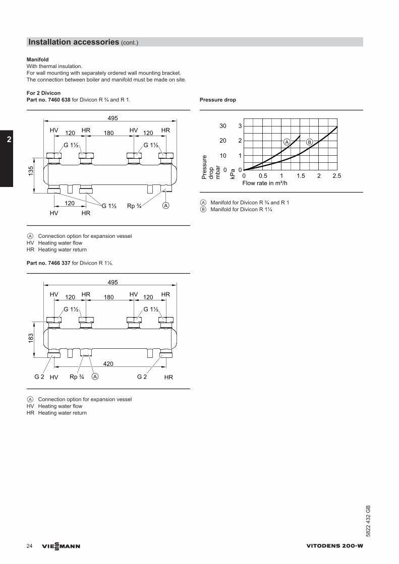
ManifoldWith thermal insulation.For wall mounting with separately ordered wall mounting bracket.The connection between boiler and manifold must be made on site.
For 2 DiviconPart no. 7460 638 for Divicon R ¾ and R 1.
HV HR HV HR120
495
HV HR120
135
120
A
180
G 1½ Rp ¾
G 1½ G 1½
A Connection option for expansion vesselHV Heating water flowHR Heating water return
Part no. 7466 337 for Divicon R 1¼.
HV HR HV HR120
495
HV HR
420
183
120
A
180
G 2Rp ¾G 2
G 1½ G 1½
A Connection option for expansion vesselHV Heating water flowHR Heating water return
Pressure drop
00 0.5 1 1.5 2Flow rate in m³/h
1
2
3
2.5kPa
A B
0
10
20
30
Pres
sure
drop
m
bar
A Manifold for Divicon R ¾ and R 1B Manifold for Divicon R 1¼
Installation accessories (cont.)
24 VIESMANN VITODENS 200-W
2
5822
432
GB
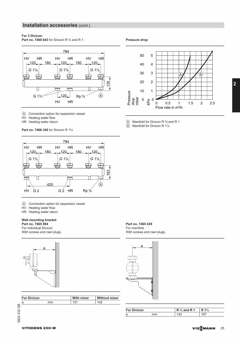
For 3 DiviconPart no. 7460 643 for Divicon R ¾ and R 1.
120HV HR HV HR HV HR
120 120
784
HV HR13
5
A
180 180
120G 1½ Rp ¾
G 1½ G 1½ G 1½
A Connection option for expansion vesselHV Heating water flowHR Heating water return
Part no. 7466 340 for Divicon R 1¼
120HV HR HV HR HV HR
120 120
784
HV HR
183
A
180 180
420
G 2 Rp ¾G 2
G 1½ G 1½ G 1½
A Connection option for expansion vesselHV Heating water flowHR Heating water return
Pressure drop
00 0.5 1 1.5 2Flow rate in m³/h
1
2
3
2.5kPa
4
5
A B
0
10
20
30
Pres
sure
drop
m
bar
40
50
A Manifold for Divicon R ¾ and R 1B Manifold for Divicon R 1¼
Wall mounting bracketPart no. 7465 894For individual Divicon.With screws and rawl plugs.
a
For Divicon With mixer Without mixera mm 151 142
Part no. 7465 439For manifold.With screws and rawl plugs.
a
For Divicon R ¾ and R 1 R 1¼a mm 142 167
Installation accessories (cont.)
VITODENS 200-W VIESMANN 25
5822
432
GB
2
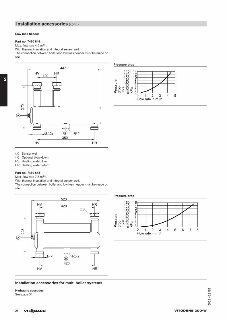
Low loss header
Part no. 7460 649Max. flow rate 4.5 m3/h.With thermal insulation and integral sensor well.The connection between boiler and low loss header must be made onsite.
120HV HR
447
275
G 1½
A
Rp 1B
350HV HR
A Sensor wellB Optional blow-downHV Heating water flowHR Heating water return
Pressure drop
Pres
sure
drop
00 1 2 3 4 5Flow rate in m³/h
2468
101214
kPa
020406080
100120140
mba
r
Part no. 7460 648Max. flow rate 7.5 m3/h.With thermal insulation and integral sensor well.The connection between boiler and low loss header must be made onsite.
G 2
420
523
295
A
HV HR
Rp 2
G 2
B420
HV HR
Pressure drop
0 1 2 3 4 5Flow rate in m³/h
6 7 8
Pres
sure
drop
02468
101214
kPa
020406080
100120140
mba
r
16160
Installation accessories for multi boiler systems
Hydraulic cascadesSee page 34.
Installation accessories (cont.)
26 VIESMANN VITODENS 200-W
2
5822
432
GB
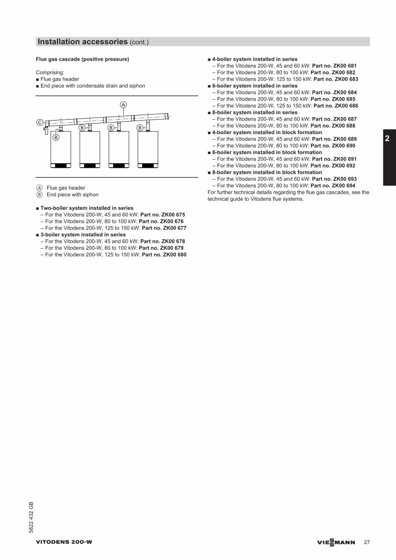
Flue gas cascade (positive pressure)
Comprising:■ Flue gas header■ End piece with condensate drain and siphon
A
C
B
B BB
A Flue gas headerB End piece with siphon
■ Two-boiler system installed in series– For the Vitodens 200-W, 45 and 60 kW: Part no. ZK00 675– For the Vitodens 200-W, 80 to 100 kW: Part no. ZK00 676– For the Vitodens 200-W, 125 to 150 kW: Part no. ZK00 677
■ 3-boiler system installed in series– For the Vitodens 200-W, 45 and 60 kW: Part no. ZK00 678– For the Vitodens 200-W, 80 to 100 kW: Part no. ZK00 679– For the Vitodens 200-W, 125 to 150 kW: Part no. ZK00 680
■ 4-boiler system installed in series– For the Vitodens 200-W, 45 and 60 kW: Part no. ZK00 681– For the Vitodens 200-W, 80 to 100 kW: Part no. ZK00 682– For the Vitodens 200-W, 125 to 150 kW: Part no. ZK00 683
■ 6-boiler system installed in series– For the Vitodens 200-W, 45 and 60 kW: Part no. ZK00 684– For the Vitodens 200-W, 80 to 100 kW: Part no. ZK00 685– For the Vitodens 200-W, 125 to 150 kW: Part no. ZK00 686
■ 8-boiler system installed in series– For the Vitodens 200-W, 45 and 60 kW: Part no. ZK00 687– For the Vitodens 200-W, 80 to 100 kW: Part no. ZK00 688
■ 4-boiler system installed in block formation– For the Vitodens 200-W, 45 and 60 kW: Part no. ZK00 689– For the Vitodens 200-W, 80 to 100 kW: Part no. ZK00 690
■ 6-boiler system installed in block formation– For the Vitodens 200-W, 45 and 60 kW: Part no. ZK00 691– For the Vitodens 200-W, 80 to 100 kW: Part no. ZK00 692
■ 8-boiler system installed in block formation– For the Vitodens 200-W, 45 and 60 kW: Part no. ZK00 693– For the Vitodens 200-W, 80 to 100 kW: Part no. ZK00 694
For further technical details regarding the flue gas cascades, see thetechnical guide to Vitodens flue systems.
Installation accessories (cont.)
VITODENS 200-W VIESMANN 27
5822
432
GB
2
3.1 Product descriptionFor details regarding DHW cylinders, see the technical guide to theVitodens up to 35 kW, or separate datasheets.
Design information
4.1 Positioning, installation
Siting conditions for open flue operation (appliance type B)(Type B23 and B33)
In rooms where air contamination from halogenated hydrocar-bons may occur, such as hairdressing salons, printing shops, chemi-cal cleaners, laboratories, etc., operate the Vitodens only as a roomsealed system.If in doubt, please contact us.Wall mounted boilers should not be installed in areas subject to verydusty conditions.The installation location must be kept free from frost and must be ade-quately ventilated.Provide a condensate drain and a discharge pipe for the safety valvein the installation room.The maximum ambient temperature of the system should not exceed35 °C.If these instructions are not observed, any consequential appliancedamage directly related to any of these causes is excluded from ourwarranty.a When installing in Austria, observe all current safety regulations
as defined by ÖVGW-TR Gas (G1), ÖNORM, ÖVGW, ÖVE andlocally applicable standards.
Vitodens 200-W from 60 kW and multi boiler systemsInstall boilers from 50 kW in accordance with the Combustion Order(FeuVo) [Germany] [or local regulations] in a separate installationroom. Fit the mains isolator outside the installation room.
Combustion air aperturesGas equipment with a total rated heating output in excess of 50 kWmust be provided with combustion air apertures leading to the outside.The cross-section should be at least 150 cm2 and should be 2 cm2
larger for each kW above 50 kW rated heating output. This cross-sec-tion may not be split over more than 2 apertures (observe FeuVo andTRGI 2008 point 5.5.4 [or local regulations]).
Example:Vitodens 200-W, 3 × 60 kW Total rated heating output 180 kW 150 cm2 + 130 × 2 cm2 = 410 cm2 or 2 × 205 cm2 .The combustion air apertures should measure at least 410 cm2 or 2 ×205 cm2.
Multi boiler systems with flue systems under positive pressureThe Vitodens 200-W multi boiler systems with common pressurisedflue systems are designed for open flue operation (type B).For further details, see the technical guide on flue systems for theVitodens.
Installation room (up to 50 kW)
Permissible:■ Boiler installation on the same floor■ Adjacent rooms with interconnected room air supply (larders, base-
ments, utility rooms etc.)■ Attic rooms, but only with adequate minimum chimney height to
DIN 18160 – 4 m above inlet (negative pressure operation).
Not permissible:■ Stairwells and communal hallways; exception: Detached and two-
family houses of low height (top edge of floor in the top storey <7 m above ground level)
■ Bathrooms and toilets without outside windows with shaft ventilation■ Rooms where explosive or flammable materials are stored■ Rooms that are ventilated mechanically or via individual duct sys-
tems to DIN 18117-1.
Observe all local fire regulations.
Connection on the flue gas side(For further details, see the technical guide "Flue systems for theVitodens")The connection piece to the chimney should be as short as possible.Therefore position the Vitodens as closely to the chimney as possi-ble.No special protective measures or clearances towards combustibleobjects, e.g. furniture, packaging or similar, need to be taken/observed.The surface temperatures of the Vitodens and the flue system neverexceed 85 ºC.
ExtractorsWhen installing appliances with extraction to the outside (cookerhoods, extractor fans etc.), ensure that air extraction will not createnegative pressure inside the installation room. A return flow of fluegases could otherwise result if the ventilation system and the Vitodensare operated simultaneously. In such cases, install an interlock cir-cuit.For this, the internal extension H2 (accessories) can be used. Thisswitches the extractors off when the burner is started.
Safety equipment for the installation roomViessmann heat sources are tested and approved in accordance withall safety regulations and are therefore fail-safe. Unpredictable, exter-nal factors may, in the rarest of cases, lead to the potentially harmfulescape of carbon monoxide (CO). For this case, we recommend usinga CO limiter. This can be ordered as a separate accessory (part no.7499 330).
DHW cylinder
28 VIESMANN VITODENS 200-W
3
5822
432
GB
Installation conditions for room sealed operation (appliance type C)The Vitodens can be installed as appliance type C13x, C33x, C43x, C53x,C63x, C83x or C93x to TRGl 2008, for room sealed operation independ-ent of the size and ventilation of the installation room.It may, for example, be installed in recreation rooms, in other livingspaces, in ancillary rooms without ventilation, in cupboards (open atthe top) and recesses, without maintaining minimum clearances tocombustible parts, as well as in attic rooms (pitched attics and longpanes) where the balanced flue pipe can be routed directly through theroof. Since the flue pipe connection piece for room sealed operation issurrounded by combustion air (coaxial pipe), no clearances towardscombustible parts need to be maintained (for further details, see thetechnical guide "Flue systems for the Vitodens").The installation area must be safe from the risk of frost.Provide a condensate drain and a discharge pipe for the safety valvein the installation room.Electrical interlocks for extractors (extractor hoods, etc.) are notrequired with room sealed operation.
Vitodens 200-W from 60 kWIn accordance with the Combustion Order (FeuVo) [Germany] boilersfrom 50 kW must be installed in a separate room [observe local regu-lations]. Fit the mains isolator outside the installation room.
Appropriate ventilation air and extract air apertures are required inaccordance with TRGI (see the technical guide on flue systems for theVitodens).
Installation in a garageTests carried out by the Gaswärme-Institut e.V., Essen, have con-firmed that the Vitodens is suitable for installation in garages.When installing this boiler in garages, maintain a clearance betweenthe floor and the burner of at least 500 mm. Install a frame or deflector(provided on site) to protect the boiler against mechanical damage.
Safety equipment for the installation roomViessmann heat sources are tested and approved in accordance withall safety regulations and are therefore fail-safe. Unpredictable, exter-nal factors may, in the rarest of cases, lead to the potentially harmfulescape of carbon monoxide (CO). For this case, we recommend usinga CO limiter. This can be ordered as a separate accessory (part no.7499 330).
Operation of the Vitodens in wet areasThe Vitodens is approved for installation in wet areas (IP rating:IP X 4D, splashproof)
When installing the Vitodens in wet areas, observe the safety zonesand minimum wall clearances according to VDE 0100 [or local regu-lations]. The Vitodens 200-W may be installed in safety zone 1.
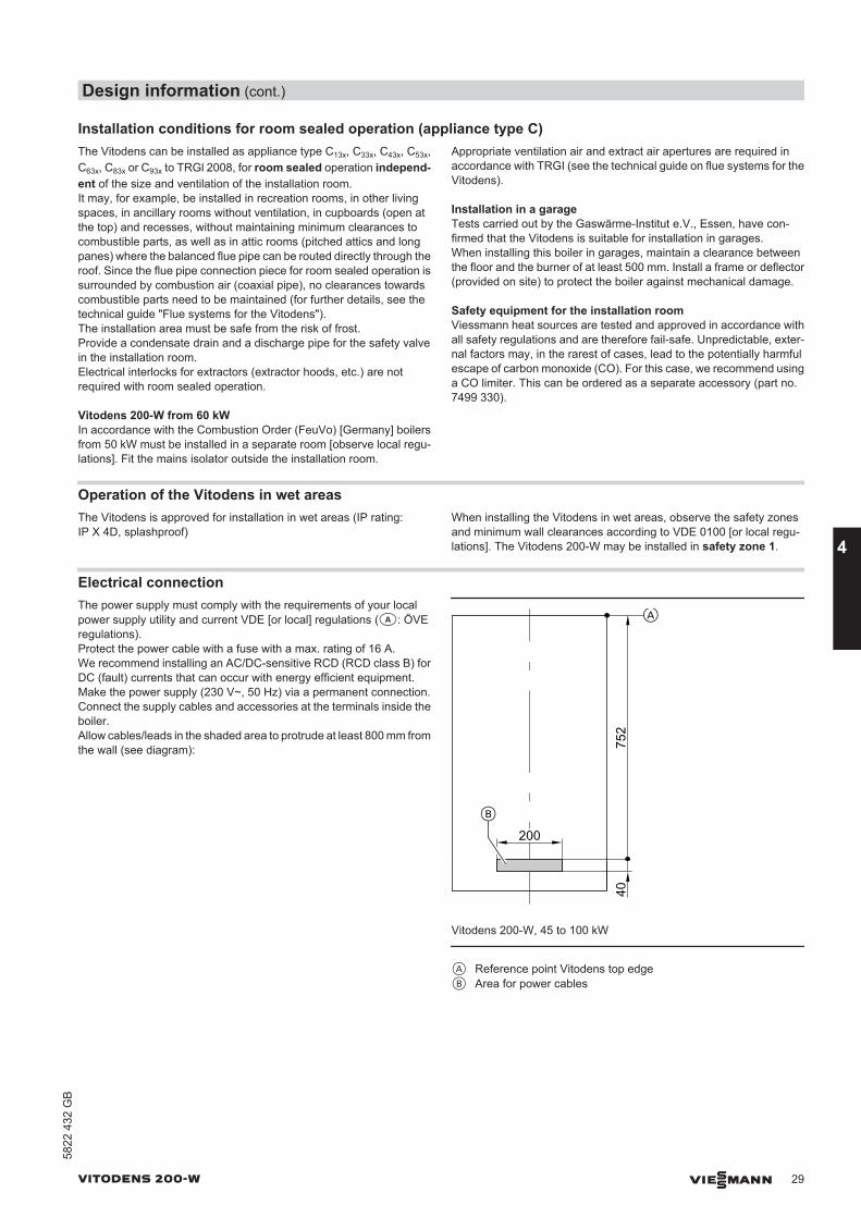
Electrical connectionThe power supply must comply with the requirements of your localpower supply utility and current VDE [or local] regulations (a: ÖVEregulations).Protect the power cable with a fuse with a max. rating of 16 A.We recommend installing an AC/DC-sensitive RCD (RCD class B) forDC (fault) currents that can occur with energy efficient equipment.Make the power supply (230 V~, 50 Hz) via a permanent connection.Connect the supply cables and accessories at the terminals inside theboiler.Allow cables/leads in the shaded area to protrude at least 800 mm fromthe wall (see diagram):
40
200
752
B
A
Vitodens 200-W, 45 to 100 kW
A Reference point Vitodens top edgeB Area for power cables
Design information (cont.)
VITODENS 200-W VIESMANN 29
5822
432
GB
4
40
200
855
B
A
Vitodens 200-W, 125 to 150 kW
A Reference point Vitodens top edgeB Area for power cables
Recommended leads/cables
NYM 3 G 1.5 mm2 2-core min. 0.75 mm2 4-core 1.5 mm2
or3-core 1.5 mm2 without green/yellowwire
– Power cables (also for accessories)– DHW circulation pump
– Extension AM1 or EA1– Outside temperature sensor– Vitotronic 200-H (LON)– Extension kit for heating circuit with mixer
(KM BUS)– Vitotrol 100, type UTDB (230 V)– Vitotrol 200A– Vitotrol 300A– Vitocomfort 200– Wireless base station– Radio clock receiver
– Vitotrol 100, type UTDB-RF (230 V)– Vitotrol 100, type UTA
Interlock switchInstall an interlock for open flue operation if an extractor (e.g. cookerhood) is fitted any room that is part of the interconnected combustionair supply.For this, the internal extension H2 (accessories) can be used. Thisswitches the extractors off when the burner is started.
Power supply for accessoriesThe power supply for accessories can be provided directly at the con-trol unit.This connection is switched by the system ON/OFF switch.If the total system current exceeds 6 A, connect one or more exten-sions directly to the mains supply via an ON/OFF switch.
Where the boiler is installed in a wet area, the power supply connectionof accessories must not be made at the control unit.
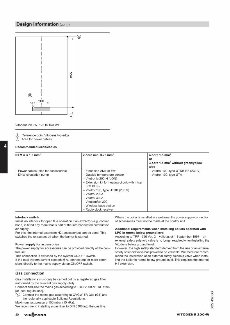
Additional requirements when installing boilers operated withLPG in rooms below ground levelAccording to TRF 1996 Vol. 2 – valid as of 1 September 1997 – anexternal safety solenoid valve is no longer required when installing theVitodens below ground level.However, the high safety standard derived from the use of an externalsafety solenoid valve has proved to be valuable. We therefore recom-mend the installation of an external safety solenoid valve when instal-ling the boiler in rooms below ground level. This requires the internalH1 extension.
Gas connectionGas installations must only be carried out by a registered gas fitterauthorised by the relevant gas supply utility.Connect and size the mains gas according to TRGI 2008 or TRF 1996[or local regulations].a Connect the mains gas according to ÖVGW-TR Gas (G1) and
the regionally applicable Building Regulations.Maximum test pressure 150 mbar (15 kPa).We recommend installing a gas filter to DIN 3386 into the gas line.
Design information (cont.)
30 VIESMANN VITODENS 200-W
4
5822
432
GB
Thermally activated safety shut-off valveAccording to paragraph 4, section 5 of the FeuVo 2008 [or local reg-ulations], thermally activated shut-off equipment that will shut off thegas supply if the external temperature exceeds 100 ºC must be instal-led in combustion equipment or in gas lines immediately upstream ofthe combustion equipment. These valves must isolate the gas supplyfor at least 30 minutes up to a temperature of 650 ºC. This is intendedto prevent the formation of explosive gas mixtures in the event of afire.The gas shut-off valves supplied with the Vitodens are equipped withintegral thermally activated safety shut-off valves.
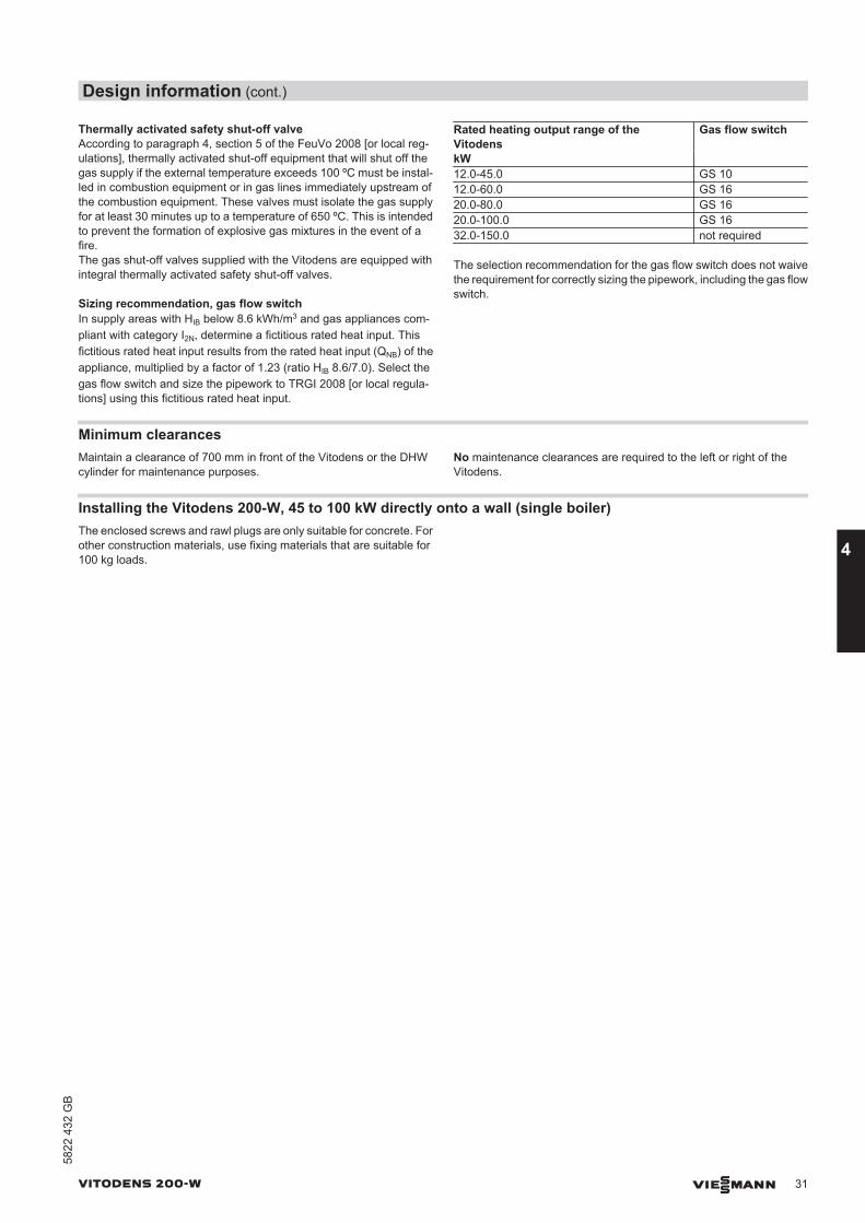
Sizing recommendation, gas flow switchIn supply areas with HIB below 8.6 kWh/m3 and gas appliances com-pliant with category I2N, determine a fictitious rated heat input. Thisfictitious rated heat input results from the rated heat input (QNB) of theappliance, multiplied by a factor of 1.23 (ratio HIB 8.6/7.0). Select thegas flow switch and size the pipework to TRGI 2008 [or local regula-tions] using this fictitious rated heat input.
Rated heating output range of theVitodens
Gas flow switch
kW12.0-45.0 GS 1012.0-60.0 GS 1620.0-80.0 GS 1620.0-100.0 GS 1632.0-150.0 not required
The selection recommendation for the gas flow switch does not waivethe requirement for correctly sizing the pipework, including the gas flowswitch.
Minimum clearancesMaintain a clearance of 700 mm in front of the Vitodens or the DHWcylinder for maintenance purposes.
No maintenance clearances are required to the left or right of theVitodens.
Installing the Vitodens 200-W, 45 to 100 kW directly onto a wall (single boiler)The enclosed screws and rawl plugs are only suitable for concrete. Forother construction materials, use fixing materials that are suitable for100 kg loads.
Design information (cont.)
VITODENS 200-W VIESMANN 31
5822
432
GB
4
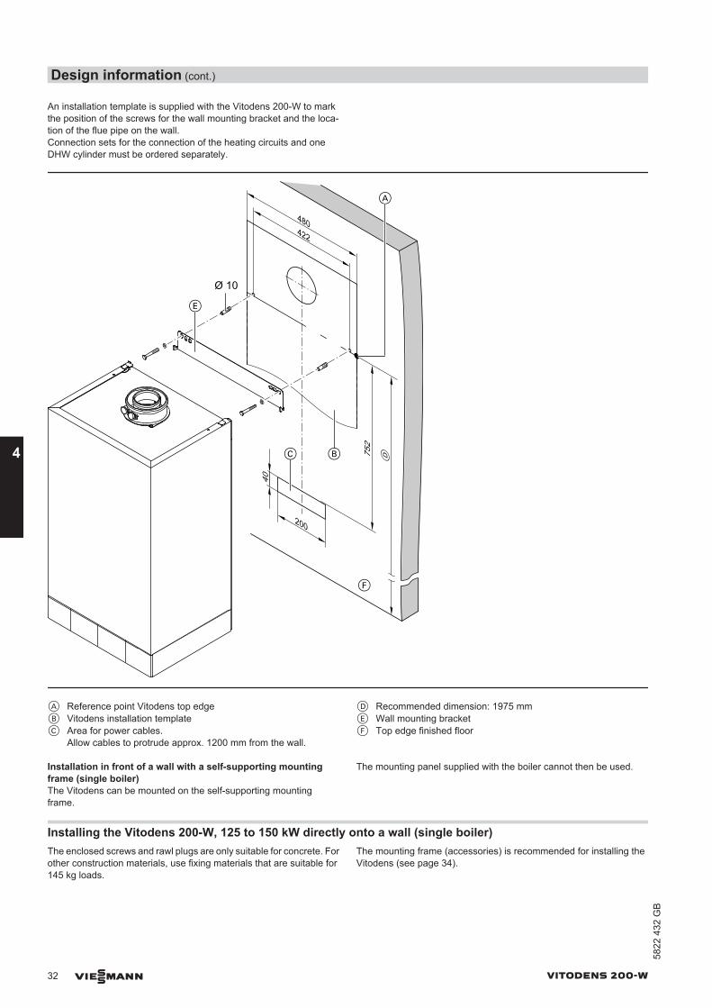
An installation template is supplied with the Vitodens 200-W to markthe position of the screws for the wall mounting bracket and the loca-tion of the flue pipe on the wall.Connection sets for the connection of the heating circuits and oneDHW cylinder must be ordered separately.
40
422
480
Ø 10
752
200
A
D
B
F
E
C
A Reference point Vitodens top edgeB Vitodens installation template C Area for power cables.
Allow cables to protrude approx. 1200 mm from the wall.
D Recommended dimension: 1975 mmE Wall mounting bracketF Top edge finished floor
Installation in front of a wall with a self-supporting mountingframe (single boiler)The Vitodens can be mounted on the self-supporting mountingframe.
The mounting panel supplied with the boiler cannot then be used.
Installing the Vitodens 200-W, 125 to 150 kW directly onto a wall (single boiler)The enclosed screws and rawl plugs are only suitable for concrete. Forother construction materials, use fixing materials that are suitable for145 kg loads.
The mounting frame (accessories) is recommended for installing theVitodens (see page 34).
Design information (cont.)
32 VIESMANN VITODENS 200-W
4
5822
432
GB
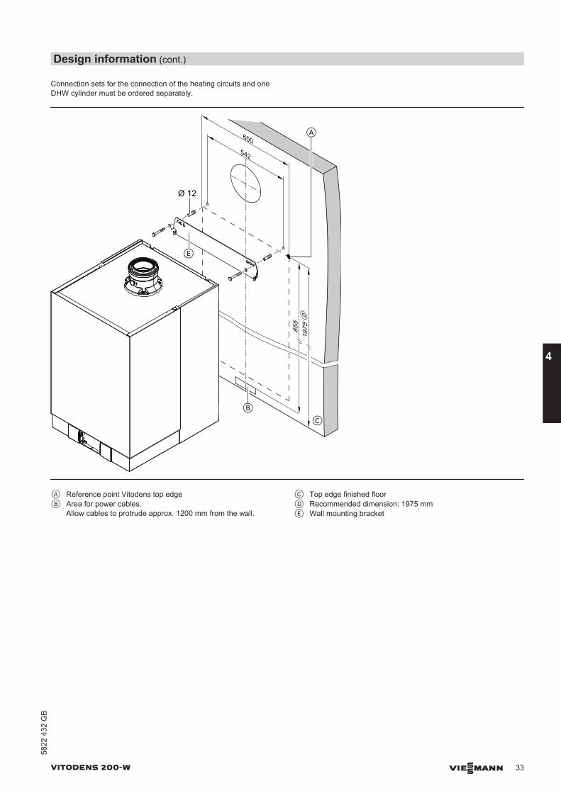
Connection sets for the connection of the heating circuits and oneDHW cylinder must be ordered separately.
1975
B
C
D
A
Ø 12
855
E
600542
A Reference point Vitodens top edgeB Area for power cables.
Allow cables to protrude approx. 1200 mm from the wall.
C Top edge finished floorD Recommended dimension: 1975 mmE Wall mounting bracket
Design information (cont.)
VITODENS 200-W VIESMANN 33
5822
432
GB
4
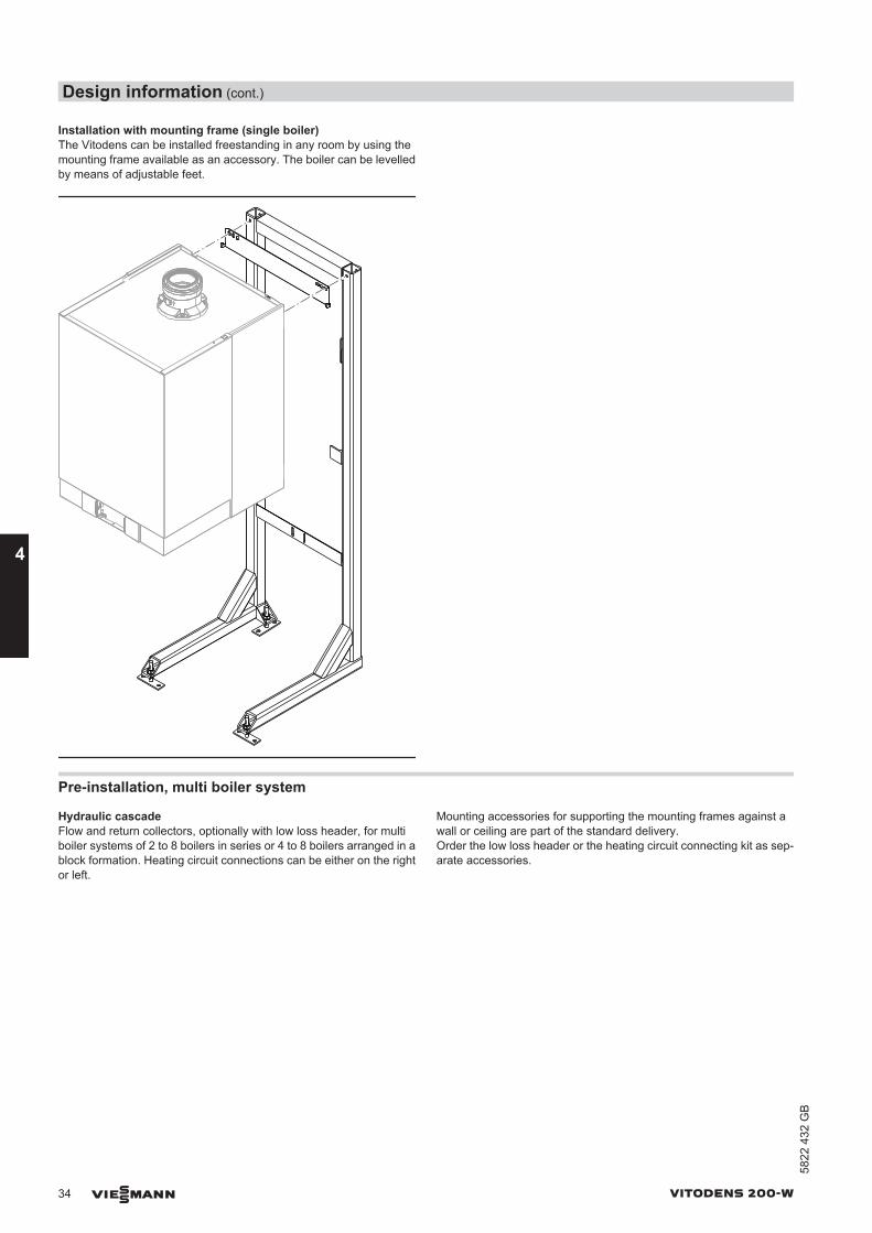
Installation with mounting frame (single boiler)The Vitodens can be installed freestanding in any room by using themounting frame available as an accessory. The boiler can be levelledby means of adjustable feet.
Pre-installation, multi boiler system
Hydraulic cascadeFlow and return collectors, optionally with low loss header, for multiboiler systems of 2 to 8 boilers in series or 4 to 8 boilers arranged in ablock formation. Heating circuit connections can be either on the rightor left.
Mounting accessories for supporting the mounting frames against awall or ceiling are part of the standard delivery.Order the low loss header or the heating circuit connecting kit as sep-arate accessories.
Design information (cont.)
34 VIESMANN VITODENS 200-W
4
5822
432
GB
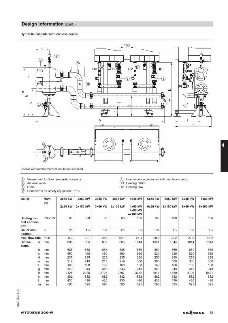
Hydraulic cascade with low loss header
k
cb
a
hf
g
AB
100
E E
HV HR HV HR
lm
HV
HRe
d
CRP 1
D
D
Shown without the thermal insulation supplied
A Sensor well for flow temperature sensorB Air vent valveC DrainD Connectors for safety equipment Rp ½
E Connection accessories with circulation pumpHR Heating returnHV Heating flow
Boiler Num-ber
2x45 kW 2x80 kW 3x45 kW 3x80 kW 4x45 kW 6x45 kW 6x80 kW 8x45 kW 8x80 kW
2x60 kW 2x100 kW 3x60 kW 3x100 kW 4x60 kW4x80 kW
4x100 kW
6x60 kW 6x100 kW 8x60 kW 8x100 kW
Heating cir-cuit connec-tion
PN6/DN 80 80 80 80 100 100 100 100 100
Boiler con-nection
G 1½ 1½ 1½ 1½ 1½ 1½ 1½ 1½ 1½
Max. flow rate m3/h 6.9 12.1 10.3 18.1 24.1 20.6 36.2 27.6 48.2Dimen-sions
a mm 805 805 805 805 1044 1044 1044 1044 1044
b mm 688 688 688 688 860 860 860 860 860 c mm 460 460 460 460 520 520 520 520 520 d mm 235 235 235 235 250 250 250 250 250 e mm 219 219 219 219 300 300 300 300 300 f mm 168 168 168 168 168 168 168 168 168 g mm 343 343 343 343 343 343 343 343 343 h mm 2125 2125 2707 2707 3382 4544 4659 5706 5821 k mm 882 882 882 882 882 882 882 882 882 l mm 430 430 430 430 430 430 430 430 430 m mm 595 595 595 595 595 595 595 595 595
Design information (cont.)
VITODENS 200-W VIESMANN 35
5822
432
GB
4
Boiler Number 2x125 kW 3x125 kW 4x125 kW 6x125 kW 2x150 kW 3x150 kW 4x150 kW 6x150 kW
Heating circuit connection PN6/DN 100 100 150 150Boiler connection G 2 2 2 2Max. flow rate m3/h 17.2 25.8 34.4 51.6Dimensions a mm 1218 1218 1218 1218 b mm 972 972 972 972 c mm 520 520 520 520 d mm 380 380 380 380 e mm 419 419 419 419 f mm 168 168 168 168 g mm 343 343 343 343 h mm 2461 3159 3974 5372 k mm 1025 1025 1025 1025 l mm 520 520 520 520 m mm 710 710 710 710
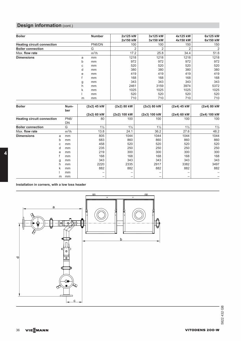
Boiler Num-ber
(2x2) 45 kW (2x2) 80 kW (2x3) 80 kW (2x4) 45 kW (2x4) 80 kW
(2x2) 60 kW (2x2) 100 kW (2x3) 100 kW (2x4) 60 kW (2x4) 100 kWHeating circuit connection PN6/
DN80 100 100 100 100
Boiler connection G 1½ 1½ 1½ 1½ 1½Max. flow rate m3/h 13.8 24.1 36.2 27.6 48.2Dimensions a mm 805 1044 1044 1044 1044 b mm 683 860 860 860 860 c mm 458 520 520 520 520 d mm 235 250 250 250 250 e mm 219 300 300 300 300 f mm 168 168 168 168 168 g mm 343 343 343 343 343 h mm 2220 2335 2917 3382 3497 k mm 882 882 882 882 882 l mm – – – – – m mm – – – – –
Installation in corners, with a low loss header
d
c
b
a
Design information (cont.)
36 VIESMANN VITODENS 200-W
4
5822
432
GB
Boiler Num-ber
2x45 kW 2x80 kW 3x45 kW 3x80 kW 4x45 kW 6x45 kW 6x80 kW 8x45 kW 8x80 kW
2x60 kW 2x100 kW 3x60 kW 3x100 kW 4x60 kW4x80 kW
4x100 kW
6x60 kW 6x100 kW 8x60 kW 8x100 kW
Heating cir-cuit connec-tion
PN6/DN 65 65 65 65 100 100 100 100 100
Dimen-sions
a mm 927 927 927 927 1022 1022 1137 1022 1137
b mm 1198 1198 1780 1780 2360 3522 3522 4684 4684 c mm 277 277 277 277 277 277 277 277 277 d mm 1204 1204 1204 1204 1299 1299 1414 1414 1414
Boiler Number 2x125 kW 3x125 kW 4x125 kW 6x125 kW 2x150 kW 3x150 kW 4x150 kW 6x150 kW
Heating circuit connection PN6/DN 100 100 100 100
Dimensions a mm 1022 1022 1022 1022 b mm 1439 2137 2952 4350 c mm 277 277 277 277 d mm 1299 1299 1299 1299
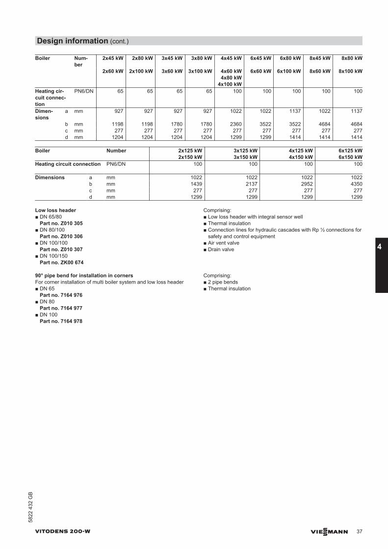
Low loss header■ DN 65/80
Part no. Z010 305■ DN 80/100
Part no. Z010 306■ DN 100/100
Part no. Z010 307■ DN 100/150
Part no. ZK00 674
Comprising:■ Low loss header with integral sensor well■ Thermal insulation■ Connection lines for hydraulic cascades with Rp ½ connections for
safety and control equipment■ Air vent valve■ Drain valve
90° pipe bend for installation in cornersFor corner installation of multi boiler system and low loss header■ DN 65
Part no. 7164 976■ DN 80
Part no. 7164 977■ DN 100
Part no. 7164 978
Comprising:■ 2 pipe bends■ Thermal insulation
Design information (cont.)
VITODENS 200-W VIESMANN 37
5822
432
GB
4
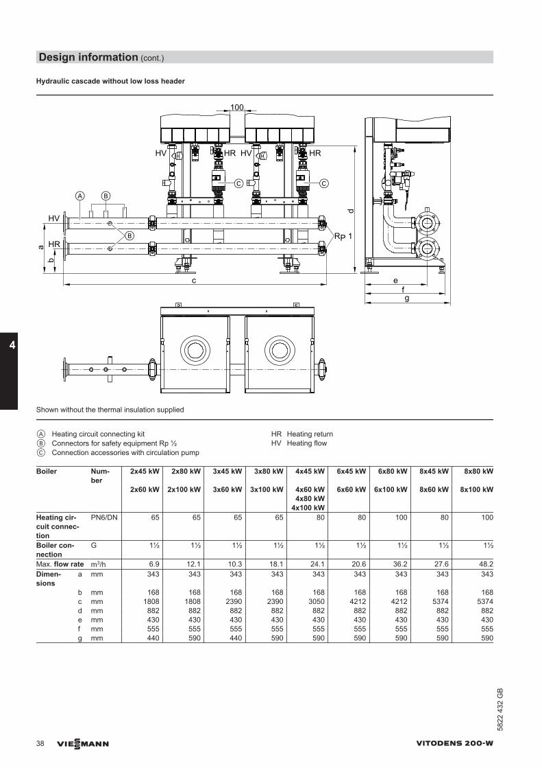
Hydraulic cascade without low loss header
ba
A
HR
HV
HV HR HV HR
efg
c
100
RP 1
B
B
C C
d
Shown without the thermal insulation supplied
A Heating circuit connecting kitB Connectors for safety equipment Rp ½C Connection accessories with circulation pump
HR Heating returnHV Heating flow
Boiler Num-ber
2x45 kW 2x80 kW 3x45 kW 3x80 kW 4x45 kW 6x45 kW 6x80 kW 8x45 kW 8x80 kW
2x60 kW 2x100 kW 3x60 kW 3x100 kW 4x60 kW4x80 kW
4x100 kW
6x60 kW 6x100 kW 8x60 kW 8x100 kW
Heating cir-cuit connec-tion
PN6/DN 65 65 65 65 80 80 100 80 100
Boiler con-nection
G 1½ 1½ 1½ 1½ 1½ 1½ 1½ 1½ 1½
Max. flow rate m3/h 6.9 12.1 10.3 18.1 24.1 20.6 36.2 27.6 48.2Dimen-sions
a mm 343 343 343 343 343 343 343 343 343
b mm 168 168 168 168 168 168 168 168 168 c mm 1808 1808 2390 2390 3050 4212 4212 5374 5374 d mm 882 882 882 882 882 882 882 882 882 e mm 430 430 430 430 430 430 430 430 430 f mm 555 555 555 555 555 555 555 555 555 g mm 440 590 440 590 590 590 590 590 590
Design information (cont.)
38 VIESMANN VITODENS 200-W
4
5822
432
GB

Boiler Number 2x125 kW 3x125 kW 4x125 kW 6x125 kW 2x150 kW 3x150 kW 4x150 kW 6x150 kW
Heating circuit connection PN6/DN 80 80 100 100
Boiler connection G 2 2 2 2Max. flow rate m3/h 17.2 25.8 34.4 51.6Dimensions a mm 343 343 343 343 b mm 168 168 168 168 c mm 2129 2827 3527 4925 d mm 1025 1025 1025 1025 e mm 520 520 520 520 f mm 710 710 710 710 g mm 755 755 755 755
Boiler Number (2x2) 45 kW (2x2) 80 kW (2x3) 80 kW (2x4) 45 kW (2x4) 80 kW (2x2) 60 kW (2x2) 100 kW (2x3) 100 kW (2x4) 60 kW (2x4) 100 kW
Heating circuit con-nection
PN6/DN 80 100 100 100 100
Boiler connection G 1½ 1½ 1½ 1½ 1½Max. flow rate m3/h 13.8 24.1 36.2 27.6 48.2Dimensions a mm 343 343 343 343 343 b mm 168 168 168 168 168 c mm 1888 1888 2470 3050 3050 d mm 882 882 882 882 882 e mm – – – – – f mm – – – – – g mm – – – – –
Heating circuit connecting kit■ DN 65
Part no. 7453 093■ DN 80
Part no. 7453 094■ DN 100
Part no. 7453 095
Comprising:■ Connection lines for hydraulic cascades with Rp ½ connections for
safety and control equipment■ Thermal insulation
Corner installation of multi boiler system and heating circuit connecting kit
d
c
b
a
Design information (cont.)
VITODENS 200-W VIESMANN 39
5822
432
GB
4
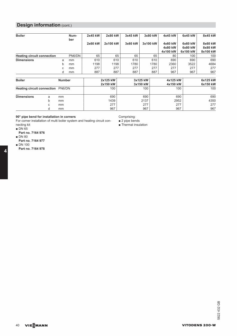
Boiler Num-ber
2x45 kW 2x80 kW 3x45 kW 3x80 kW 4x45 kW 6x45 kW 8x45 kW
2x60 kW 2x100 kW 3x60 kW 3x100 kW 4x60 kW4x80 kW
4x100 kW
6x60 kW6x80 kW
6x100 kW
8x60 kW8x80 kW
8x100 kWHeating circuit connection PN6/DN 65 65 65 65 80 100 100Dimensions a mm 610 610 610 610 690 690 690 b mm 1198 1198 1780 1780 2360 3522 4684 c mm 277 277 277 277 277 277 277 d mm 887 887 887 887 967 967 967
Boiler Number 2x125 kW 3x125 kW 4x125 kW 6x125 kW 2x150 kW 3x150 kW 4x150 kW 6x150 kW
Heating circuit connection PN6/DN 100 100 100 100
Dimensions a mm 690 690 690 690 b mm 1439 2137 2952 4350 c mm 277 277 277 277 d mm 967 967 967 967
90° pipe bend for installation in cornersFor corner installation of multi boiler system and heating circuit con-necting kit■ DN 65
Part no. 7164 976■ DN 80
Part no. 7164 977■ DN 100
Part no. 7164 978
Comprising:■ 2 pipe bends■ Thermal insulation
Design information (cont.)
40 VIESMANN VITODENS 200-W
4
5822
432
GB
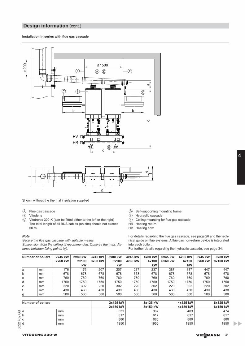
Installation in series with flue gas cascade
200 1500
F FA D
b b
da
c
C B
g
E
C
HVHR
e f
Shown without the thermal insulation supplied
A Flue gas cascadeB VitodensC Vitotronic 300-K (can be fitted either to the left or the right)
The total length of all BUS cables (on site) should not exceed50 m.
D Self-supporting mounting frameE Hydraulic cascadeF Ceiling mounting for flue gas cascadeHR Heating returnHV Heating flow
NoteSecure the flue gas cascade with suitable means.Suspension from the ceiling is recommended. Observe the max. dis-tance between fixing points F.
For details regarding the flue gas cascade, see page 26 and the tech-nical guide on flue systems. A flue gas non-return device is integratedinto each boiler.For further details regarding the hydraulic cascade, see page 34.
Number of boilers 2x45 kW 2x80 kW 3x45 kW 3x80 kW 4x45 kW 4x80 kW 6x45 kW 6x80 kW 8x45 kW 8x80 kW 2x60 kW 2x100
kW3x60 kW 3x100
kW4x60 kW 4x100
kW6x60 kW 6x100
kW8x60 kW 8x100 kW
a mm 176 176 207 207 237 237 387 387 447 447b mm 678 678 678 678 678 678 678 678 678 678c mm 760 760 760 760 760 760 760 760 760 760d mm 1750 1750 1750 1750 1750 1750 1750 1750 1750 1750e mm 220 302 220 302 220 302 220 302 220 302f mm 430 430 430 430 430 430 430 430 430 430g mm 580 580 580 580 580 580 580 580 580 580
Number of boilers 2x125 kW 3x125 kW 4x125 kW 6x125 kW 2x150 kW 3x150 kW 4x150 kW 6x150 kW
a mm 331 367 403 474b mm 617 617 617 617c mm 880 880 880 880d mm 1950 1950 1950 1950
Design information (cont.)
VITODENS 200-W VIESMANN 41
5822
432
GB
4
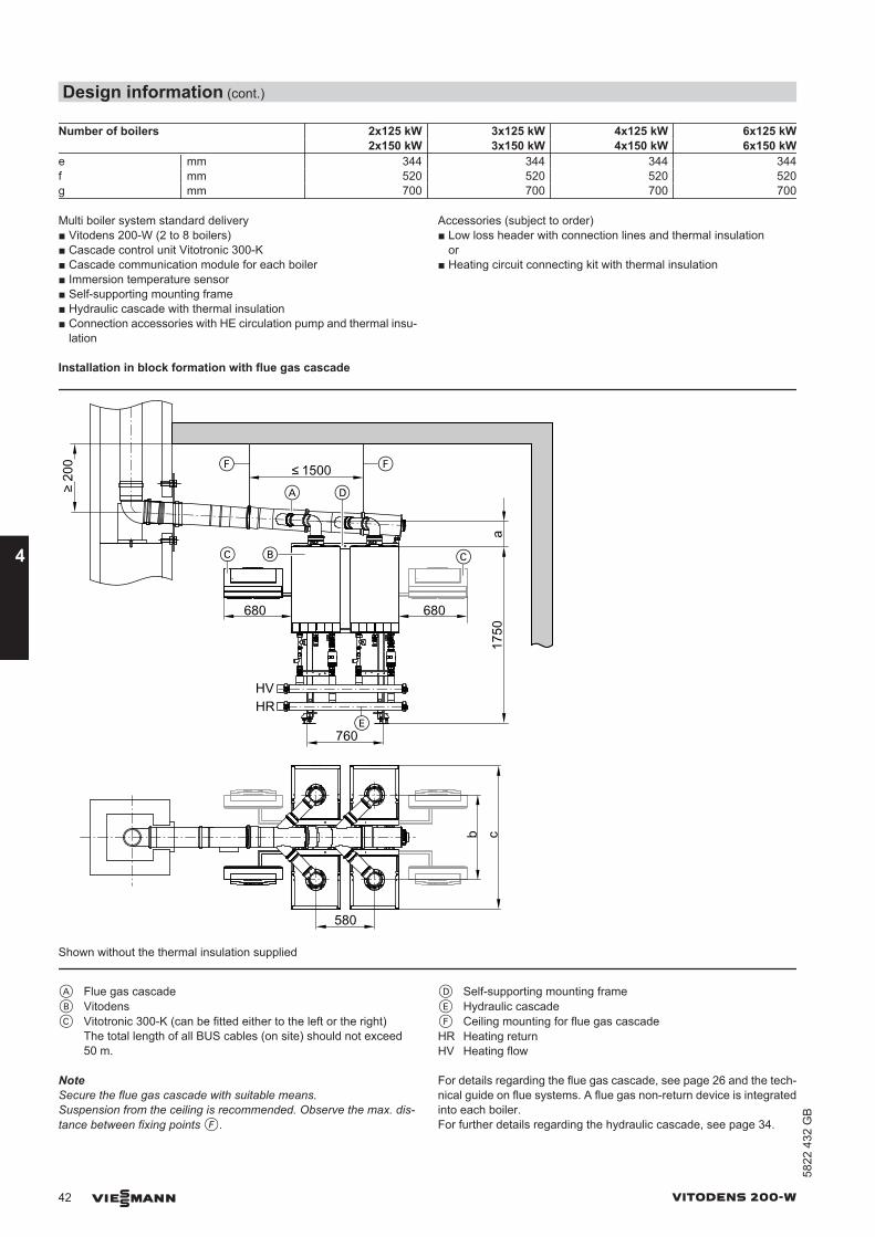
Number of boilers 2x125 kW 3x125 kW 4x125 kW 6x125 kW 2x150 kW 3x150 kW 4x150 kW 6x150 kW
e mm 344 344 344 344f mm 520 520 520 520g mm 700 700 700 700
Multi boiler system standard delivery■ Vitodens 200-W (2 to 8 boilers)■ Cascade control unit Vitotronic 300-K■ Cascade communication module for each boiler■ Immersion temperature sensor■ Self-supporting mounting frame■ Hydraulic cascade with thermal insulation■ Connection accessories with HE circulation pump and thermal insu-
lation
Accessories (subject to order)■ Low loss header with connection lines and thermal insulation
or■ Heating circuit connecting kit with thermal insulation
Installation in block formation with flue gas cascade
a17
50
680 680
1500b c
200 F F
A D
C B
E760
C
580
HVHR
Shown without the thermal insulation supplied
A Flue gas cascadeB VitodensC Vitotronic 300-K (can be fitted either to the left or the right)
The total length of all BUS cables (on site) should not exceed50 m.
D Self-supporting mounting frameE Hydraulic cascadeF Ceiling mounting for flue gas cascadeHR Heating returnHV Heating flow
NoteSecure the flue gas cascade with suitable means.Suspension from the ceiling is recommended. Observe the max. dis-tance between fixing points F.
For details regarding the flue gas cascade, see page 26 and the tech-nical guide on flue systems. A flue gas non-return device is integratedinto each boiler.For further details regarding the hydraulic cascade, see page 34.
Design information (cont.)
42 VIESMANN VITODENS 200-W
4
5822
432
GB
Boiler (2x2) 45 kW (2x2) 80 kW (2x3) 80 kW (2x4) 45 kW (2x4) 80 kW (2x2) 60 kW (2x2) 100 kW (2x3) 100 kW (2x4) 60 kW (2x4) 100 kW
a mm 176 176 207 176 237b mm 680 843 843 680 843c mm 1350 1422 1422 1350 1422
Multi boiler system standard delivery■ Vitodens 200-W (4 to 8 boilers)■ Cascade control unit Vitotronic 300-K■ Cascade communication module for each boiler■ Immersion temperature sensor■ Hydraulic cascade with thermal insulation■ Self-supporting mounting frame■ Connection accessories with HE circulation pump and thermal insu-
lation
Accessories (subject to order)■ Low loss header with connection lines and thermal insulation
or■ Heating circuit connecting kit with thermal insulation
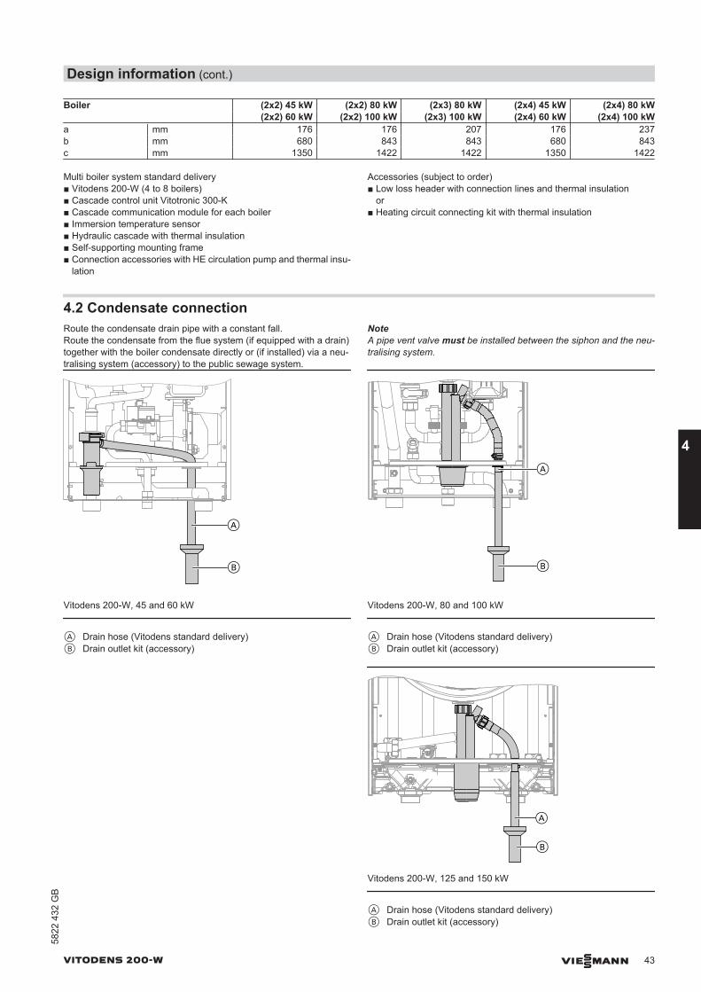
4.2 Condensate connectionRoute the condensate drain pipe with a constant fall.Route the condensate from the flue system (if equipped with a drain)together with the boiler condensate directly or (if installed) via a neu-tralising system (accessory) to the public sewage system.
NoteA pipe vent valve must be installed between the siphon and the neu-tralising system.
A
B
Vitodens 200-W, 45 and 60 kW
A Drain hose (Vitodens standard delivery)B Drain outlet kit (accessory)
A
B
Vitodens 200-W, 80 and 100 kW
A Drain hose (Vitodens standard delivery)B Drain outlet kit (accessory)
A
B
Vitodens 200-W, 125 and 150 kW
A Drain hose (Vitodens standard delivery)B Drain outlet kit (accessory)
Design information (cont.)
VITODENS 200-W VIESMANN 43
5822
432
GB
4
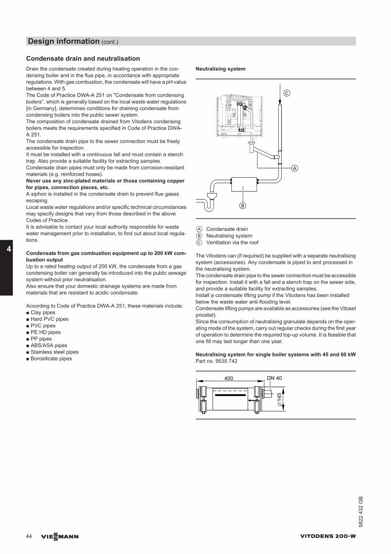
Condensate drain and neutralisationDrain the condensate created during heating operation in the con-densing boiler and in the flue pipe, in accordance with appropriateregulations. With gas combustion, the condensate will have a pH valuebetween 4 and 5.The Code of Practice DWA-A 251 on "Condensate from condensingboilers", which is generally based on the local waste water regulations[in Germany], determines conditions for draining condensate fromcondensing boilers into the public sewer system.The composition of condensate drained from Vitodens condensingboilers meets the requirements specified in Code of Practice DWA-A 251.The condensate drain pipe to the sewer connection must be freelyaccessible for inspection.It must be installed with a continuous fall and must contain a stenchtrap. Also provide a suitable facility for extracting samples.Condensate drain pipes must only be made from corrosion-resistantmaterials (e.g. reinforced hoses).Never use any zinc-plated materials or those containing copperfor pipes, connection pieces, etc. A siphon is installed in the condensate drain to prevent flue gasesescaping.Local waste water regulations and/or specific technical circumstancesmay specify designs that vary from those described in the aboveCodes of Practice.It is advisable to contact your local authority responsible for wastewater management prior to installation, to find out about local regula-tions.
Condensate from gas combustion equipment up to 200 kW com-bustion outputUp to a rated heating output of 200 kW, the condensate from a gascondensing boiler can generally be introduced into the public sewagesystem without prior neutralisation.Also ensure that your domestic drainage systems are made frommaterials that are resistant to acidic condensate.
According to Code of Practice DWA-A 251, these materials include:■ Clay pipes■ Hard PVC pipes■ PVC pipes■ PE HD pipes■ PP pipes■ ABS/ASA pipes■ Stainless steel pipes■ Borosilicate pipes
Neutralising system
A
C
B
A Condensate drainB Neutralising systemC Ventilation via the roof
The Vitodens can (if required) be supplied with a separate neutralisingsystem (accessories). Any condensate is piped to and processed inthe neutralising system.The condensate drain pipe to the sewer connection must be accessiblefor inspection. Install it with a fall and a stench trap on the sewer side,and provide a suitable facility for extracting samples.Install a condensate lifting pump if the Vitodens has been installedbelow the waste water anti-flooding level.Condensate lifting pumps are available as accessories (see the Vitosetpricelist).Since the consumption of neutralising granulate depends on the oper-ating mode of the system, carry out regular checks during the first yearof operation to determine the required top-up volume. It is feasible thatone fill may last longer than one year.
Neutralising system for single boiler systems with 45 and 60 kWPart no. 9535 742
400 DN 40
145
Design information (cont.)
44 VIESMANN VITODENS 200-W
4
5822
432
GB
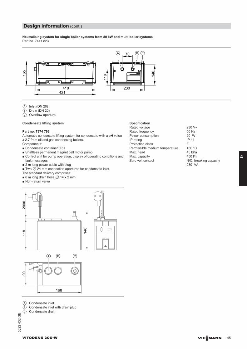
Neutralising system for single boiler systems from 80 kW and multi boiler systemsPart no. 7441 823
410421
11016
5
140
230
CBA 70
A Inlet (DN 20)B Drain (DN 20)C Overflow aperture
Condensate lifting system
Part no. 7374 796Automatic condensate lifting system for condensate with a pH value≥ 2.7 from oil and gas condensing boilers.Components:■ Condensate container 0.5 l■ Shaftless permanent magnet ball motor pump■ Control unit for pump operation, display of operating conditions and
fault messages■ 2 m long power cable with plug■ Two 7 24 mm connection apertures for condensate inletThe standard delivery comprises:■ 6 m long drain hose 7 14 x 2 mm■ Non-return valve
2000
90
168
148
118
A B C
A Condensate inletB Condensate inlet with drain plugC Condensate drain
SpecificationRated voltage 230 V~Rated frequency 50 HzPower consumption 20 WIP rating IP 44 Protection class FPermissible medium temperature +60 °CMax. head 45 kPaMax. capacity 450 l/hZero volt contact N/C, breaking capacity
230 VA
Design information (cont.)
VITODENS 200-W VIESMANN 45
5822
432
GB
4
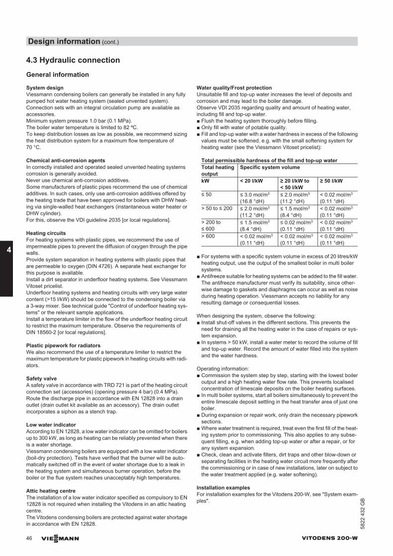
4.3 Hydraulic connection
General information
System designViessmann condensing boilers can generally be installed in any fullypumped hot water heating system (sealed unvented system). Connection sets with an integral circulation pump are available asaccessories.Minimum system pressure 1.0 bar (0.1 MPa).The boiler water temperature is limited to 82 ºC.To keep distribution losses as low as possible, we recommend sizingthe heat distribution system for a maximum flow temperature of70 °C.
Chemical anti-corrosion agentsIn correctly installed and operated sealed unvented heating systemscorrosion is generally avoided.Never use chemical anti-corrosion additives.Some manufacturers of plastic pipes recommend the use of chemicaladditives. In such cases, only use anti-corrosion additives offered bythe heating trade that have been approved for boilers with DHW heat-ing via single-walled heat exchangers (instantaneous water heater orDHW cylinder).For this, observe the VDI guideline 2035 [or local regulations].
Heating circuitsFor heating systems with plastic pipes, we recommend the use ofimpermeable pipes to prevent the diffusion of oxygen through the pipewalls.Provide system separation in heating systems with plastic pipes thatare permeable to oxygen (DIN 4726). A separate heat exchanger forthis purpose is available.Install a dirt separator in underfloor heating systems. See ViessmannVitoset pricelist.Underfloor heating systems and heating circuits with very large watercontent (>15 l/kW) should be connected to the condensing boiler viaa 3-way mixer. See technical guide "Control of underfloor heating sys-tems" or the relevant sample applications.Install a temperature limiter in the flow of the underfloor heating circuitto restrict the maximum temperature. Observe the requirements ofDIN 18560-2 [or local regulations].
Plastic pipework for radiatorsWe also recommend the use of a temperature limiter to restrict themaximum temperature for plastic pipework in heating circuits with radi-ators.
Safety valveA safety valve in accordance with TRD 721 is part of the heating circuitconnection set (accessories) (opening pressure 4 bar) (0.4 MPa).Route the discharge pipe in accordance with EN 12828 into a drainoutlet (drain outlet kit available as an accessory). The drain outletincorporates a siphon as a stench trap.
Low water indicatorAccording to EN 12828, a low water indicator can be omitted for boilersup to 300 kW, as long as heating can be reliably prevented when thereis a water shortage.Viessmann condensing boilers are equipped with a low water indicator(boil-dry protection). Tests have verified that the burner will be auto-matically switched off in the event of water shortage due to a leak inthe heating system and simultaneous burner operation, before theboiler or the flue system reaches unacceptably high temperatures.
Attic heating centreThe installation of a low water indicator specified as compulsory to EN12828 is not required when installing the Vitodens in an attic heatingcentre.The Vitodens condensing boilers are protected against water shortagein accordance with EN 12828.
Water quality/Frost protectionUnsuitable fill and top-up water increases the level of deposits andcorrosion and may lead to the boiler damage.Observe VDI 2035 regarding quality and amount of heating water,including fill and top-up water.■ Flush the heating system thoroughly before filling.■ Only fill with water of potable quality.■ Fill and top-up water with a water hardness in excess of the following
values must be softened, e.g. with the small softening system forheating water (see the Viessmann Vitoset pricelist):
Total permissible hardness of the fill and top-up waterTotal heatingoutput
Specific system volume
kW < 20 l/kW ≥ 20 l/kW to< 50 l/kW
≥ 50 l/kW
≤ 50 ≤ 3.0 mol/m3
(16.8 °dH)≤ 2.0 mol/m3
(11.2 °dH)< 0.02 mol/m3
(0.11 °dH)> 50 to ≤ 200 ≤ 2.0 mol/m3
(11.2 °dH)≤ 1.5 mol/m3
(8.4 °dH)< 0.02 mol/m3
(0.11 °dH)> 200 to≤ 600
≤ 1.5 mol/m3
(8.4 °dH)≤ 0.02 mol/m3
(0.11 °dH)< 0.02 mol/m3
(0.11 °dH)> 600 < 0.02 mol/m3
(0.11 °dH)< 0.02 mol/m3
(0.11 °dH)< 0.02 mol/m3
(0.11 °dH)
■ For systems with a specific system volume in excess of 20 litres/kWheating output, use the output of the smallest boiler in multi boilersystems.
■ Antifreeze suitable for heating systems can be added to the fill water.The antifreeze manufacturer must verify its suitability, since other-wise damage to gaskets and diaphragms can occur as well as noiseduring heating operation. Viessmann accepts no liability for anyresulting damage or consequential losses.
When designing the system, observe the following:■ Install shut-off valves in the different sections. This prevents the
need for draining all the heating water in the case of repairs or sys-tem expansion.
■ In systems > 50 kW, install a water meter to record the volume of filland top-up water. Record the amount of water filled into the systemand the water hardness.
Operating information:■ Commission the system step by step, starting with the lowest boiler
output and a high heating water flow rate. This prevents localisedconcentration of limescale deposits on the boiler heating surfaces.
■ In multi boiler systems, start all boilers simultaneously to prevent theentire limescale deposit settling in the heat transfer area of just oneboiler.
■ During expansion or repair work, only drain the necessary pipeworksections.
■ Where water treatment is required, treat even the first fill of the heat-ing system prior to commissioning. This also applies to any subse-quent filling, e.g. when adding top-up water or after a repair, or forany system expansion.
■ Check, clean and activate filters, dirt traps and other blow-down orseparating facilities in the heating water circuit more frequently afterthe commissioning or in case of new installations, later on subject tothe water treatment applied (e.g. water softening).
Installation examplesFor installation examples for the Vitodens 200-W, see "System exam-ples".
Design information (cont.)
46 VIESMANN VITODENS 200-W
4
5822
432
GB
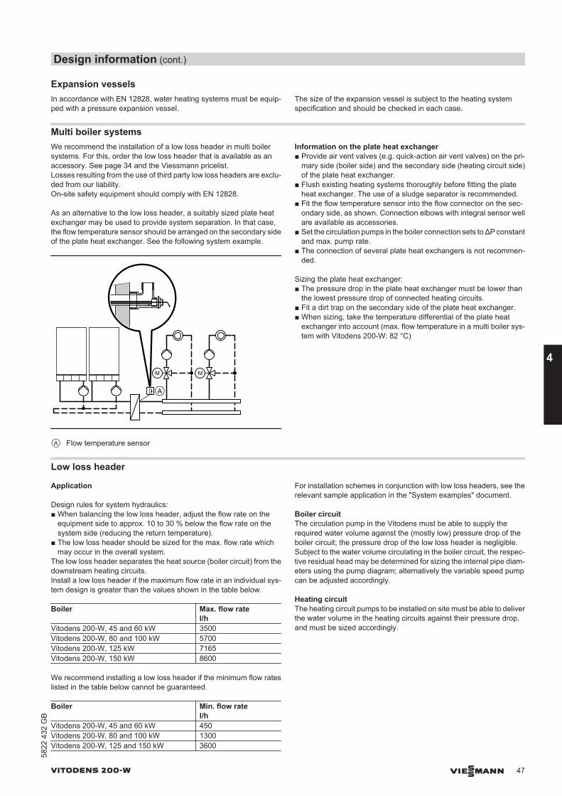
Expansion vesselsIn accordance with EN 12828, water heating systems must be equip-ped with a pressure expansion vessel.
The size of the expansion vessel is subject to the heating systemspecification and should be checked in each case.
Multi boiler systemsWe recommend the installation of a low loss header in multi boilersystems. For this, order the low loss header that is available as anaccessory. See page 34 and the Viessmann pricelist.Losses resulting from the use of third party low loss headers are exclu-ded from our liability.On-site safety equipment should comply with EN 12828.
As an alternative to the low loss header, a suitably sized plate heatexchanger may be used to provide system separation. In that case,the flow temperature sensor should be arranged on the secondary sideof the plate heat exchanger. See the following system example.
M M
A
A Flow temperature sensor
Information on the plate heat exchanger■ Provide air vent valves (e.g. quick-action air vent valves) on the pri-
mary side (boiler side) and the secondary side (heating circuit side)of the plate heat exchanger.
■ Flush existing heating systems thoroughly before fitting the plateheat exchanger. The use of a sludge separator is recommended.
■ Fit the flow temperature sensor into the flow connector on the sec-ondary side, as shown. Connection elbows with integral sensor wellare available as accessories.
■ Set the circulation pumps in the boiler connection sets to ΔP constantand max. pump rate.
■ The connection of several plate heat exchangers is not recommen-ded.
Sizing the plate heat exchanger:■ The pressure drop in the plate heat exchanger must be lower than
the lowest pressure drop of connected heating circuits.■ Fit a dirt trap on the secondary side of the plate heat exchanger.■ When sizing, take the temperature differential of the plate heat
exchanger into account (max. flow temperature in a multi boiler sys-tem with Vitodens 200-W: 82 °C)
Low loss header
Application
Design rules for system hydraulics:■ When balancing the low loss header, adjust the flow rate on the
equipment side to approx. 10 to 30 % below the flow rate on thesystem side (reducing the return temperature).
■ The low loss header should be sized for the max. flow rate whichmay occur in the overall system.
The low loss header separates the heat source (boiler circuit) from thedownstream heating circuits.Install a low loss header if the maximum flow rate in an individual sys-tem design is greater than the values shown in the table below.
Boiler Max. flow rate l/h
Vitodens 200-W, 45 and 60 kW 3500Vitodens 200-W, 80 and 100 kW 5700Vitodens 200-W, 125 kW 7165Vitodens 200-W, 150 kW 8600
We recommend installing a low loss header if the minimum flow rateslisted in the table below cannot be guaranteed.
Boiler Min. flow rate l/h
Vitodens 200-W, 45 and 60 kW 450Vitodens 200-W, 80 and 100 kW 1300Vitodens 200-W, 125 and 150 kW 3600
For installation schemes in conjunction with low loss headers, see therelevant sample application in the "System examples" document.
Boiler circuitThe circulation pump in the Vitodens must be able to supply therequired water volume against the (mostly low) pressure drop of theboiler circuit; the pressure drop of the low loss header is negligible.Subject to the water volume circulating in the boiler circuit, the respec-tive residual head may be determined for sizing the internal pipe diam-eters using the pump diagram; alternatively the variable speed pumpcan be adjusted accordingly.
Heating circuitThe heating circuit pumps to be installed on site must be able to deliverthe water volume in the heating circuits against their pressure drop,and must be sized accordingly.
Design information (cont.)
VITODENS 200-W VIESMANN 47
5822
432
GB
4
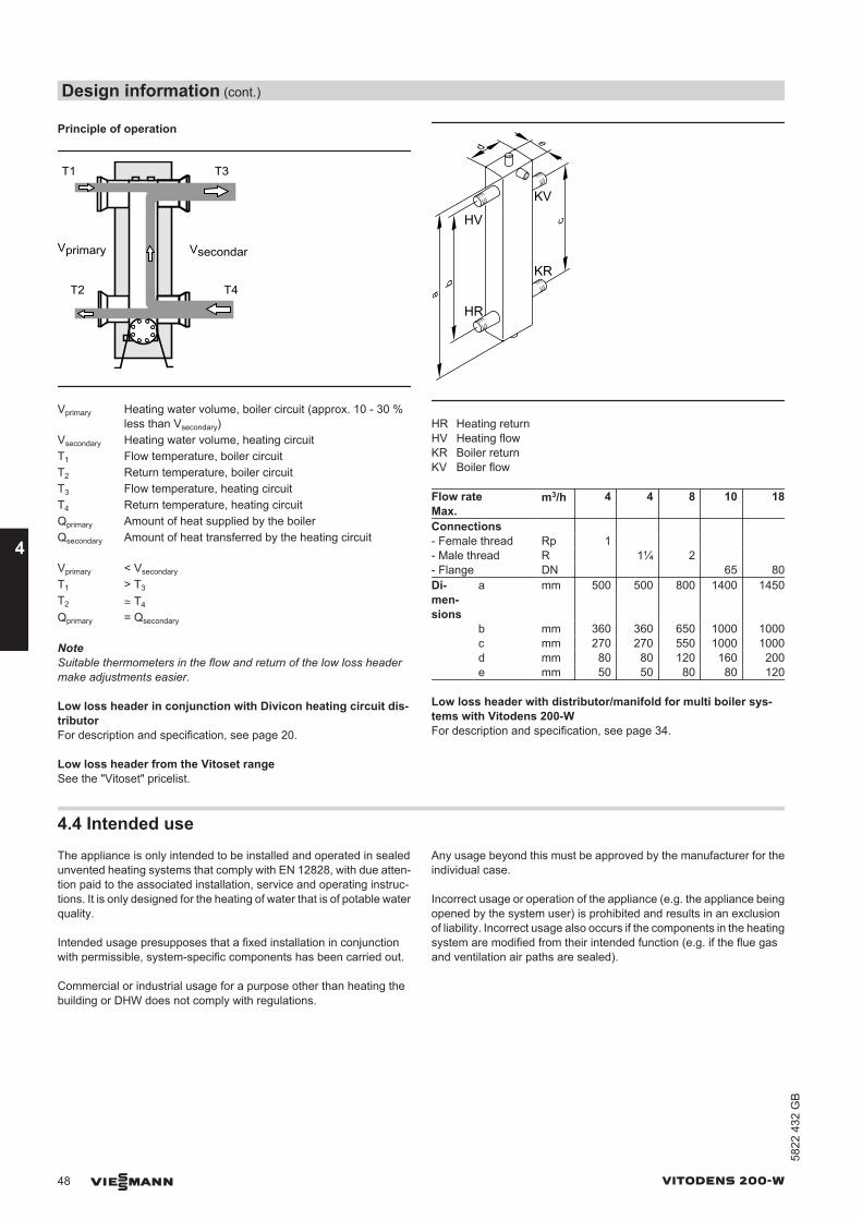
Principle of operation
T1 T3
T2 T4
VsecondaryVprimary
Vprimary Heating water volume, boiler circuit (approx. 10 - 30 %less than Vsecondary)
Vsecondary Heating water volume, heating circuitT1 Flow temperature, boiler circuitT2 Return temperature, boiler circuitT3 Flow temperature, heating circuitT4 Return temperature, heating circuitQprimary Amount of heat supplied by the boilerQsecondary Amount of heat transferred by the heating circuit
Vprimary < Vsecondary T1 > T3 T2 ≃ T4 Qprimary = Qsecondary
NoteSuitable thermometers in the flow and return of the low loss headermake adjustments easier.
Low loss header in conjunction with Divicon heating circuit dis-tributorFor description and specification, see page 20.
Low loss header from the Vitoset rangeSee the "Vitoset" pricelist.
ed
c
ba
HV
HR
KV
KR
HR Heating returnHV Heating flowKR Boiler returnKV Boiler flow
Flow rate Max.
m3/h 4 4 8 10 18
Connections - Female thread Rp 1 - Male thread R 1¼ 2 - Flange DN 65 80Di-men-sions
a mm 500 500 800 1400 1450
b mm 360 360 650 1000 1000 c mm 270 270 550 1000 1000 d mm 80 80 120 160 200 e mm 50 50 80 80 120
Low loss header with distributor/manifold for multi boiler sys-tems with Vitodens 200-WFor description and specification, see page 34.
4.4 Intended useThe appliance is only intended to be installed and operated in sealedunvented heating systems that comply with EN 12828, with due atten-tion paid to the associated installation, service and operating instruc-tions. It is only designed for the heating of water that is of potable waterquality.
Intended usage presupposes that a fixed installation in conjunctionwith permissible, system-specific components has been carried out.
Commercial or industrial usage for a purpose other than heating thebuilding or DHW does not comply with regulations.
Any usage beyond this must be approved by the manufacturer for theindividual case.
Incorrect usage or operation of the appliance (e.g. the appliance beingopened by the system user) is prohibited and results in an exclusionof liability. Incorrect usage also occurs if the components in the heatingsystem are modified from their intended function (e.g. if the flue gasand ventilation air paths are sealed).
Design information (cont.)
48 VIESMANN VITODENS 200-W
4
5822
432
GB
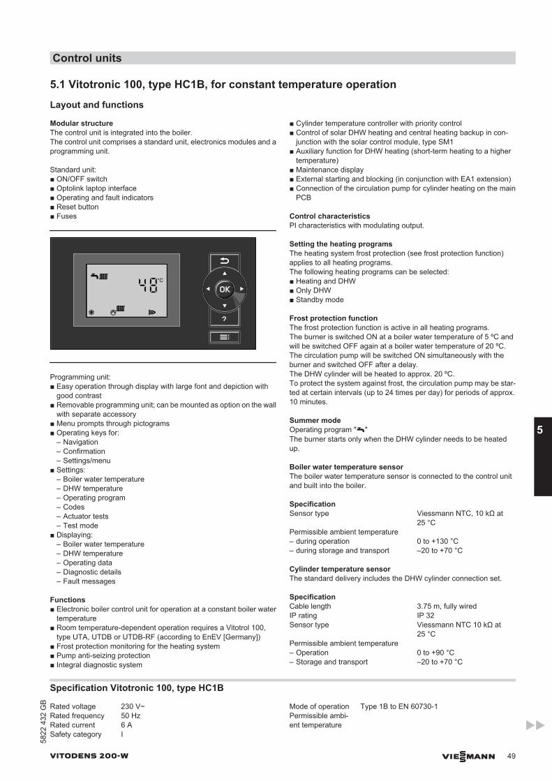
5.1 Vitotronic 100, type HC1B, for constant temperature operation
Layout and functions
Modular structureThe control unit is integrated into the boiler.The control unit comprises a standard unit, electronics modules and aprogramming unit.
Standard unit:■ ON/OFF switch■ Optolink laptop interface■ Operating and fault indicators■ Reset button■ Fuses
48°C
s A
Programming unit:■ Easy operation through display with large font and depiction with
good contrast■ Removable programming unit; can be mounted as option on the wall
with separate accessory■ Menu prompts through pictograms■ Operating keys for:
– Navigation– Confirmation– Settings/menu
■ Settings:– Boiler water temperature– DHW temperature– Operating program– Codes– Actuator tests– Test mode
■ Displaying:– Boiler water temperature– DHW temperature– Operating data– Diagnostic details– Fault messages
Functions■ Electronic boiler control unit for operation at a constant boiler water
temperature■ Room temperature-dependent operation requires a Vitotrol 100,
type UTA, UTDB or UTDB-RF (according to EnEV [Germany])■ Frost protection monitoring for the heating system■ Pump anti-seizing protection■ Integral diagnostic system
■ Cylinder temperature controller with priority control■ Control of solar DHW heating and central heating backup in con-
junction with the solar control module, type SM1■ Auxiliary function for DHW heating (short-term heating to a higher
temperature)■ Maintenance display■ External starting and blocking (in conjunction with EA1 extension)■ Connection of the circulation pump for cylinder heating on the main
PCB
Control characteristicsPI characteristics with modulating output.
Setting the heating programsThe heating system frost protection (see frost protection function)applies to all heating programs.The following heating programs can be selected:■ Heating and DHW■ Only DHW■ Standby mode
Frost protection functionThe frost protection function is active in all heating programs.The burner is switched ON at a boiler water temperature of 5 ºC andwill be switched OFF again at a boiler water temperature of 20 ºC.The circulation pump will be switched ON simultaneously with theburner and switched OFF after a delay.The DHW cylinder will be heated to approx. 20 ºC.To protect the system against frost, the circulation pump may be star-ted at certain intervals (up to 24 times per day) for periods of approx.10 minutes.
Summer modeOperating program "w" The burner starts only when the DHW cylinder needs to be heatedup.
Boiler water temperature sensorThe boiler water temperature sensor is connected to the control unitand built into the boiler.
SpecificationSensor type Viessmann NTC, 10 kΩ at
25 °CPermissible ambient temperature – during operation 0 to +130 °C– during storage and transport –20 to +70 °C
Cylinder temperature sensorThe standard delivery includes the DHW cylinder connection set.
SpecificationCable length 3.75 m, fully wiredIP rating IP 32Sensor type Viessmann NTC 10 kΩ at
25 °CPermissible ambient temperature – Operation 0 to +90 °C– Storage and transport –20 to +70 °C
Specification Vitotronic 100, type HC1B
Rated voltage 230 V~Rated frequency 50 HzRated current 6 ASafety category I
Mode of operation Type 1B to EN 60730-1Permissible ambi-ent temperature
Control units
VITODENS 200-W VIESMANN 49
5822
432
GB
5
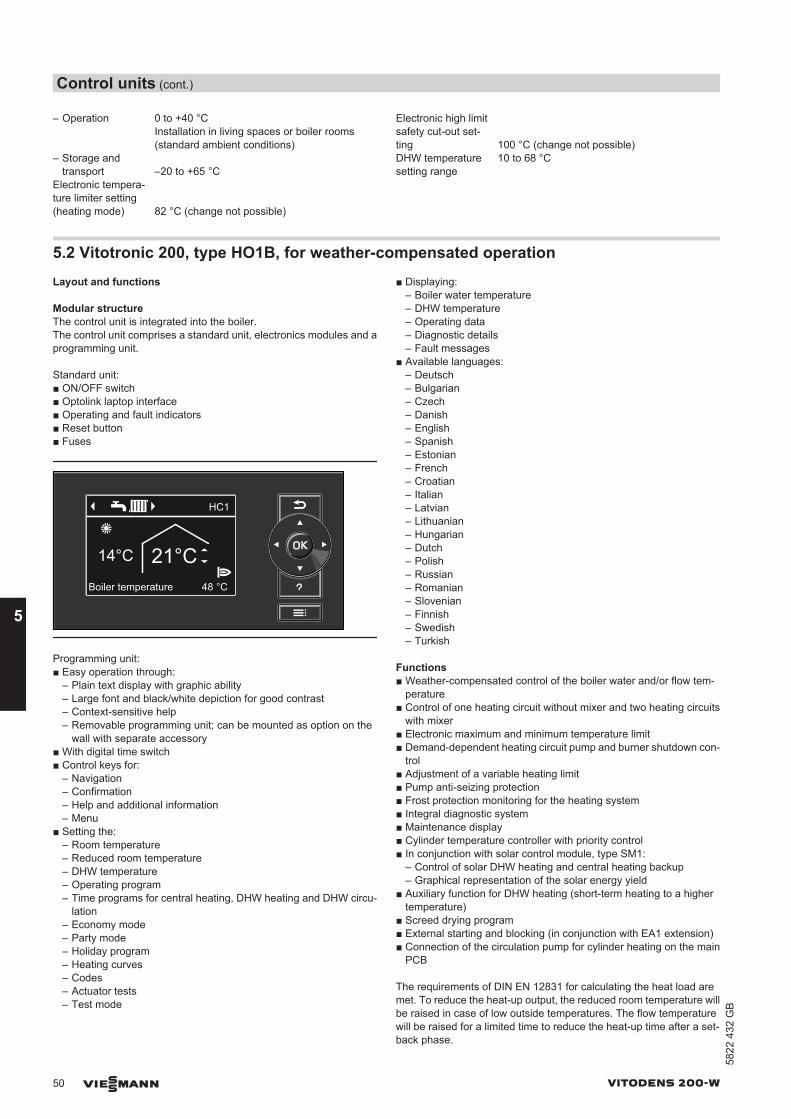
– Operation 0 to +40 °CInstallation in living spaces or boiler rooms(standard ambient conditions)
– Storage andtransport –20 to +65 °C
Electronic tempera-ture limiter setting(heating mode) 82 °C (change not possible)
Electronic high limitsafety cut-out set-ting 100 °C (change not possible)DHW temperaturesetting range
10 to 68 °C
5.2 Vitotronic 200, type HO1B, for weather-compensated operationLayout and functions
Modular structureThe control unit is integrated into the boiler.The control unit comprises a standard unit, electronics modules and aprogramming unit.
Standard unit:■ ON/OFF switch■ Optolink laptop interface■ Operating and fault indicators■ Reset button■ Fuses
48 °CBoiler temperature
HC1
14°C 21°C
Programming unit:■ Easy operation through:
– Plain text display with graphic ability– Large font and black/white depiction for good contrast– Context-sensitive help– Removable programming unit; can be mounted as option on the
wall with separate accessory■ With digital time switch■ Control keys for:
– Navigation– Confirmation– Help and additional information– Menu
■ Setting the:– Room temperature– Reduced room temperature– DHW temperature– Operating program– Time programs for central heating, DHW heating and DHW circu-
lation– Economy mode– Party mode– Holiday program– Heating curves– Codes– Actuator tests– Test mode
■ Displaying:– Boiler water temperature– DHW temperature– Operating data– Diagnostic details– Fault messages
■ Available languages:– Deutsch– Bulgarian– Czech– Danish– English– Spanish– Estonian– French– Croatian– Italian– Latvian– Lithuanian– Hungarian– Dutch– Polish– Russian– Romanian– Slovenian– Finnish– Swedish– Turkish
Functions■ Weather-compensated control of the boiler water and/or flow tem-
perature■ Control of one heating circuit without mixer and two heating circuits
with mixer■ Electronic maximum and minimum temperature limit■ Demand-dependent heating circuit pump and burner shutdown con-
trol■ Adjustment of a variable heating limit■ Pump anti-seizing protection■ Frost protection monitoring for the heating system■ Integral diagnostic system■ Maintenance display■ Cylinder temperature controller with priority control■ In conjunction with solar control module, type SM1:
– Control of solar DHW heating and central heating backup– Graphical representation of the solar energy yield
■ Auxiliary function for DHW heating (short-term heating to a highertemperature)
■ Screed drying program■ External starting and blocking (in conjunction with EA1 extension)■ Connection of the circulation pump for cylinder heating on the main
PCB
The requirements of DIN EN 12831 for calculating the heat load aremet. To reduce the heat-up output, the reduced room temperature willbe raised in case of low outside temperatures. The flow temperaturewill be raised for a limited time to reduce the heat-up time after a set-back phase.
Control units (cont.)
50 VIESMANN VITODENS 200-W
5
5822
432
GB
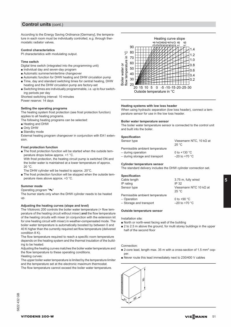
According to the Energy Saving Ordinance [Germany], the tempera-ture in each room must be individually controlled, e.g. through ther-mostatic radiator valves.
Control characteristicsPI characteristics with modulating output.
Time switchDigital time switch (integrated into the programming unit)■ Individual day and seven-day program■ Automatic summer/wintertime changeover■ Automatic function for DHW heating and DHW circulation pump■ Time, day and standard switching times for central heating, DHW
heating and the DHW circulation pump are factory-set■ Switching times are individually programmable, i.e. up to four switch-
ing periods per dayShortest switching interval: 10 minutesPower reserve: 14 days
Setting the operating programsThe heating system frost protection (see frost protection function)applies to all heating programs.The following heating programs can be selected:■ Heating and DHW■ Only DHW■ Standby modeExternal heating program changeover in conjunction with EA1 exten-sion.
Frost protection function■ The frost protection function will be started when the outside tem-
perature drops below approx. +1 °C.With frost protection, the heating circuit pump is switched ON andthe boiler water is maintained at a lower temperature of approx.20 °C.The DHW cylinder will be heated to approx. 20°C.
■ The frost protection function will be stopped when the outside tem-perature rises above approx. +3 °C.
Summer modeOperating program "w"The burner starts only when the DHW cylinder needs to be heatedup.
Adjusting the heating curves (slope and level)The Vitotronic 200 controls the boiler water temperature (= flow tem-perature of the heating circuit without mixer) and the flow temperatureof the heating circuits with mixer (in conjunction with the extension kitfor one heating circuit with mixer) in weather-compensated mode. Theboiler water temperature is automatically boosted by between 0 and40 K higher than the currently required set flow temperature (deliveredcondition 8 K).The flow temperature required to reach a specific room temperaturedepends on the heating system and the thermal insulation of the build-ing to be heated.Adjusting the heating curves matches the boiler water temperature andthe flow temperature to these operating conditions.Heating curves:The upper boiler water temperature is limited by the temperature limiterand the temperature set at the electronic maximum thermostat.The flow temperature cannot exceed the boiler water temperature.
3.2
3.4
Boile
r wat
er o
rflo
w te
mpe
ratu
re in
°C
Outside temperature in °C
Heating curve slope
3.0
2.8
2.2
2.4
2.0
1.6
1.41.21.00.80.60.40.2
9080706050403020
-20-15-10-505101520
1.8
2.6
-30-25
Heating systems with low loss headerWhen using hydraulic separation (low loss header), connect a tem-perature sensor for use in the low loss header.
Boiler water temperature sensorThe boiler water temperature sensor is connected to the control unitand built into the boiler.
SpecificationSensor type Viessmann NTC, 10 kΩ at
25 °CPermissible ambient temperature – during operation 0 to +130 °C– during storage and transport –20 to +70 °C
Cylinder temperature sensorThe standard delivery includes the DHW cylinder connection set.
SpecificationCable length 3.75 m, fully wiredIP rating IP 32Sensor type Viessmann NTC 10 kΩ at
25 °CPermissible ambient temperature – Operation 0 to +90 °C– Storage and transport –20 to +70 °C
Outside temperature sensor
Installation site:■ North or north-west facing wall of the building■ 2 to 2.5 m above the ground, for multi storey buildings in the upper
half of the second floor
Connection:■ 2-core lead, length max. 35 m with a cross-section of 1.5 mm2 cop-
per.■ Never route this lead immediately next to 230/400 V cables
41 66
80
Control units (cont.)
VITODENS 200-W VIESMANN 51
5822
432
GB
5
SpecificationIP rating IP 43 to EN 60529; ensure
through design/installationSensor type Viessmann NTC 10 kΩ, at
25 °CPermissible ambient temperature dur-ing operation, storage and transport −40 to +70 °C
Specification Vitotronic 200, type HO1B
Rated voltage 230 V~Rated frequency 50 HzRated current 6 ASafety category IPermissible ambienttemperature
– Operation 0 to +40 °CInstallation in living spaces or boiler rooms(standard ambient conditions)
– Storage and trans-port –20 to +65 °C
Electronic temperaturelimiter setting (heatingmode) 82 °C (no change possible)Electronic high limitsafety cut-out setting 100 °C (no change possible)DHW temperature set-ting range
10 to 68 °C
Heating curve settingrange
Slope 0.2 to 3.5Level –13 to 40 K
5.3 Vitotronic 300-K, type MW2B for multi boiler systems
Cascade control unit for the Vitodens 200-W with a Vitotronic 100Weather-compensated, digital cascade and heating circuit controlunit■ For multi boiler systems with Vitodens 200-W■ With boiler sequence strategy■ For up to two heating circuits with mixers (extension for heating cir-
cuits 2 and 3 required as accessory).Up to a further 32 Vitotronic 200-H heating circuit control units canbe connected via the LON BUS (LON communication modulerequired; accessory)
■ For modulating operation in conjunction with the Vitotronic 100, typeHC1B
■ With cylinder temperature controller or control unit of a primary storesystem with mixer assembly
■ Capable of communicating via LON BUS (LON communication mod-ule and terminators available as accessories)
■ With integral diagnostic system
NoteTo improve the resilience against interference/faults, the componentsof a control unit should be connected to the same phase.
Design and function
Modular designThe control unit comprises a standard unit, electronics modules and aprogramming unit.Standard unit:■ ON/OFF switch■ Emissions test switch■ Optolink laptop interface■ Operating and fault display■ Plug connection chamber
– Connection of external equipment via system plug– Connectors are plugged directly into the front of the open control
unit– Connection of three-phase consumers via additional contactors
Programming unit:■ Easy operation thanks to:
– Plain text display with graphic ability– Large font and black/white depiction for good contrast– Context-sensitive help
■ With digital time switch■ Operating keys for:
– Navigation– Confirmation– Help and additional information– Extended menu
■ Adjustment of:– Room temperature– Reduced room temperature– DHW temperature– Heating program– Time programs for central heating, DHW heating and DHW circu-
lation– Economy mode– Party mode– Holiday program– Heating curves– Codes– Actuator tests– Test mode
Control units (cont.)
52 VIESMANN VITODENS 200-W
5
5822
432
GB
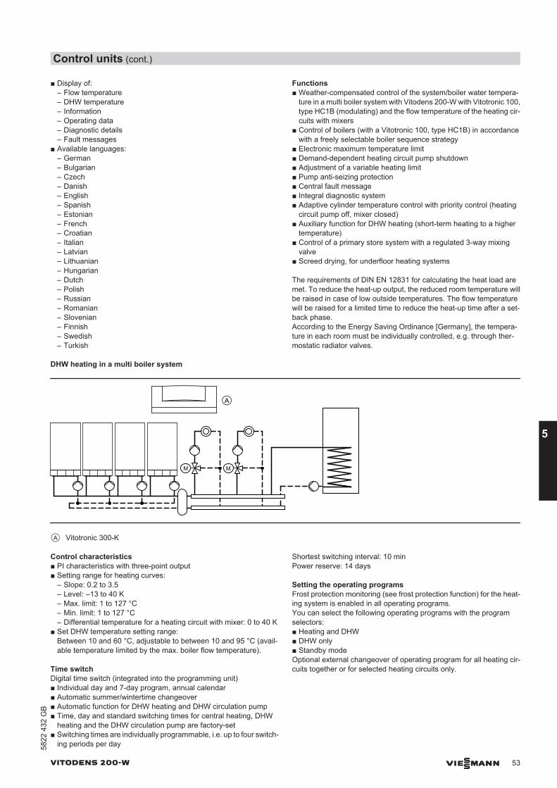
■ Display of:– Flow temperature– DHW temperature– Information– Operating data– Diagnostic details– Fault messages
■ Available languages:– German– Bulgarian– Czech– Danish– English– Spanish– Estonian– French– Croatian– Italian– Latvian– Lithuanian– Hungarian– Dutch– Polish– Russian– Romanian– Slovenian– Finnish– Swedish– Turkish
Functions■ Weather-compensated control of the system/boiler water tempera-
ture in a multi boiler system with Vitodens 200-W with Vitotronic 100,type HC1B (modulating) and the flow temperature of the heating cir-cuits with mixers
■ Control of boilers (with a Vitotronic 100, type HC1B) in accordancewith a freely selectable boiler sequence strategy
■ Electronic maximum temperature limit■ Demand-dependent heating circuit pump shutdown■ Adjustment of a variable heating limit■ Pump anti-seizing protection■ Central fault message■ Integral diagnostic system■ Adaptive cylinder temperature control with priority control (heating
circuit pump off, mixer closed)■ Auxiliary function for DHW heating (short-term heating to a higher
temperature)■ Control of a primary store system with a regulated 3-way mixing
valve■ Screed drying, for underfloor heating systems
The requirements of DIN EN 12831 for calculating the heat load aremet. To reduce the heat-up output, the reduced room temperature willbe raised in case of low outside temperatures. The flow temperaturewill be raised for a limited time to reduce the heat-up time after a set-back phase.According to the Energy Saving Ordinance [Germany], the tempera-ture in each room must be individually controlled, e.g. through ther-mostatic radiator valves.
DHW heating in a multi boiler system
A
M M
A Vitotronic 300-K
Control characteristics■ PI characteristics with three-point output■ Setting range for heating curves:
– Slope: 0.2 to 3.5– Level: –13 to 40 K– Max. limit: 1 to 127 °C– Min. limit: 1 to 127 °C– Differential temperature for a heating circuit with mixer: 0 to 40 K
■ Set DHW temperature setting range:Between 10 and 60 °C, adjustable to between 10 and 95 °C (avail-able temperature limited by the max. boiler flow temperature).
Time switchDigital time switch (integrated into the programming unit)■ Individual day and 7-day program, annual calendar■ Automatic summer/wintertime changeover■ Automatic function for DHW heating and DHW circulation pump■ Time, day and standard switching times for central heating, DHW
heating and the DHW circulation pump are factory-set■ Switching times are individually programmable, i.e. up to four switch-
ing periods per day
Shortest switching interval: 10 minPower reserve: 14 days
Setting the operating programsFrost protection monitoring (see frost protection function) for the heat-ing system is enabled in all operating programs.You can select the following operating programs with the programselectors:■ Heating and DHW■ DHW only■ Standby modeOptional external changeover of operating program for all heating cir-cuits together or for selected heating circuits only.
Control units (cont.)
VITODENS 200-W VIESMANN 53
5822
432
GB
5
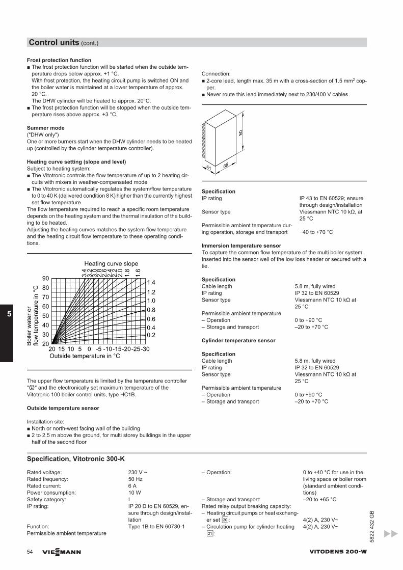
Frost protection function■ The frost protection function will be started when the outside tem-
perature drops below approx. +1 °C.With frost protection, the heating circuit pump is switched ON andthe boiler water is maintained at a lower temperature of approx.20 °C.The DHW cylinder will be heated to approx. 20°C.
■ The frost protection function will be stopped when the outside tem-perature rises above approx. +3 °C.
Summer mode("DHW only")One or more burners start when the DHW cylinder needs to be heatedup (controlled by the cylinder temperature controller).
Heating curve setting (slope and level)Subject to heating system:■ The Vitotronic controls the flow temperature of up to 2 heating cir-
cuits with mixers in weather-compensated mode■ The Vitotronic automatically regulates the system/flow temperature
to 0 to 40 K (delivered condition 8 K) higher than the currently highestset flow temperature
The flow temperature required to reach a specific room temperaturedepends on the heating system and the thermal insulation of the build-ing to be heated.Adjusting the heating curves matches the system flow temperatureand the heating circuit flow temperature to these operating condi-tions.
3.2
3.4
Boile
r wat
er o
rflo
w te
mpe
ratu
re in
°C
Outside temperature in °C
Heating curve slope
3.0
2.8
2.2
2.4
2.0
1.6
1.41.21.00.80.60.40.2
9080706050403020
-20-15-10-505101520
1.8
2.6
-30-25
The upper flow temperature is limited by the temperature controller"R" and the electronically set maximum temperature of theVitotronic 100 boiler control units, type HC1B.
Outside temperature sensor
Installation site:■ North or north-west facing wall of the building■ 2 to 2.5 m above the ground, for multi storey buildings in the upper
half of the second floor
Connection:■ 2-core lead, length max. 35 m with a cross-section of 1.5 mm2 cop-
per.■ Never route this lead immediately next to 230/400 V cables
41 66
80
SpecificationIP rating IP 43 to EN 60529; ensure
through design/installationSensor type Viessmann NTC 10 kΩ, at
25 °CPermissible ambient temperature dur-ing operation, storage and transport −40 to +70 °C
Immersion temperature sensorTo capture the common flow temperature of the multi boiler system.Inserted into the sensor well of the low loss header or secured with atie.
SpecificationCable length 5.8 m, fully wiredIP rating IP 32 to EN 60529Sensor type Viessmann NTC 10 kΩ at
25 °CPermissible ambient temperature – Operation 0 to +90 °C– Storage and transport –20 to +70 °C
Cylinder temperature sensor
SpecificationCable length 5.8 m, fully wiredIP rating IP 32 to EN 60529Sensor type Viessmann NTC 10 kΩ at
25 °CPermissible ambient temperature – Operation 0 to +90 °C– Storage and transport –20 to +70 °C
Specification, Vitotronic 300-K
Rated voltage: 230 V ~Rated frequency: 50 HzRated current: 6 APower consumption: 10 WSafety category: IIP rating: IP 20 D to EN 60529, en-
sure through design/instal-lation
Function: Type 1B to EN 60730-1Permissible ambient temperature
– Operation: 0 to +40 °C for use in theliving space or boiler room(standard ambient condi-tions)
– Storage and transport: –20 to +65 °CRated relay output breaking capacity: – Heating circuit pumps or heat exchang-
er set sÖ: 4(2) A, 230 V~– Circulation pump for cylinder heatingsA:
4(2) A, 230 V~
Control units (cont.)
54 VIESMANN VITODENS 200-W
5
5822
432
GB
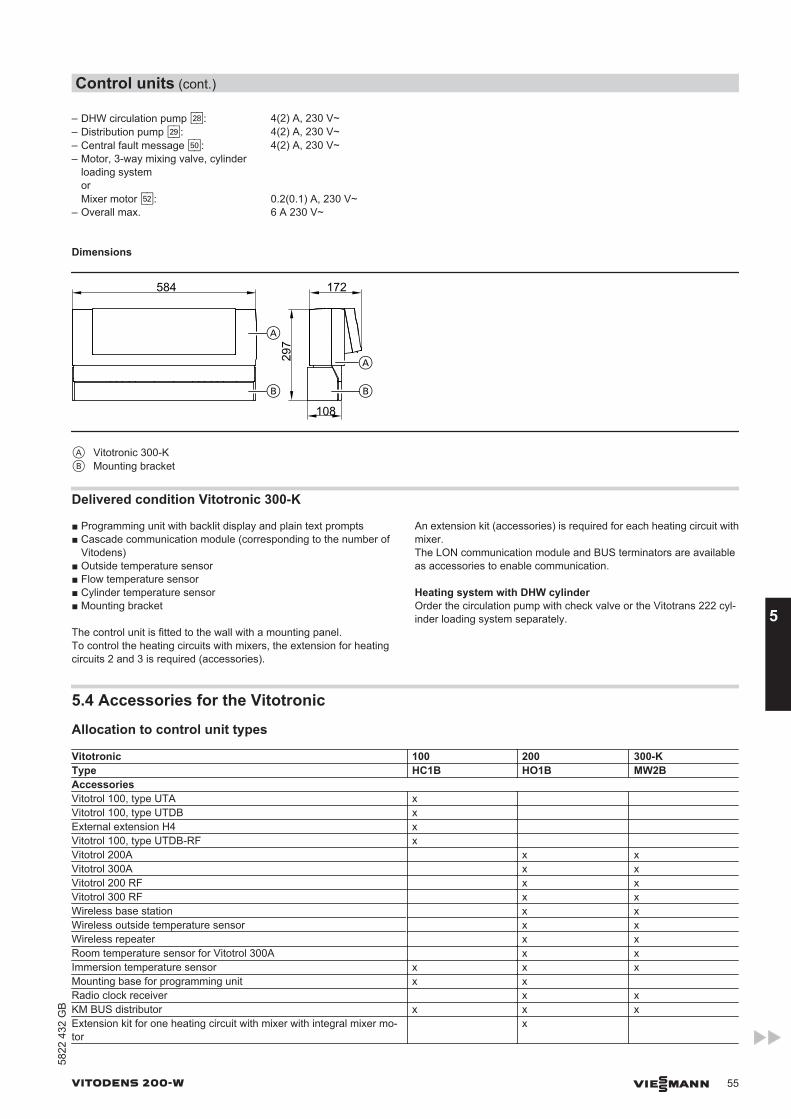
– DHW circulation pump sK: 4(2) A, 230 V~– Distribution pump sL: 4(2) A, 230 V~– Central fault message gÖ: 4(2) A, 230 V~– Motor, 3-way mixing valve, cylinder
loading systemorMixer motor gS: 0.2(0.1) A, 230 V~
– Overall max. 6 A 230 V~
Dimensions
297
584
108
172
B
A
A
B
A Vitotronic 300-KB Mounting bracket
Delivered condition Vitotronic 300-K
■ Programming unit with backlit display and plain text prompts■ Cascade communication module (corresponding to the number of
Vitodens)■ Outside temperature sensor■ Flow temperature sensor■ Cylinder temperature sensor■ Mounting bracket
The control unit is fitted to the wall with a mounting panel.To control the heating circuits with mixers, the extension for heatingcircuits 2 and 3 is required (accessories).
An extension kit (accessories) is required for each heating circuit withmixer.The LON communication module and BUS terminators are availableas accessories to enable communication.
Heating system with DHW cylinderOrder the circulation pump with check valve or the Vitotrans 222 cyl-inder loading system separately.
5.4 Accessories for the Vitotronic
Allocation to control unit types
Vitotronic 100 200 300-KType HC1B HO1B MW2BAccessoriesVitotrol 100, type UTA x Vitotrol 100, type UTDB x External extension H4 x Vitotrol 100, type UTDB-RF x Vitotrol 200A x xVitotrol 300A x xVitotrol 200 RF x xVitotrol 300 RF x xWireless base station x xWireless outside temperature sensor x xWireless repeater x xRoom temperature sensor for Vitotrol 300A x xImmersion temperature sensor x x xMounting base for programming unit x xRadio clock receiver x xKM BUS distributor x x xExtension kit for one heating circuit with mixer with integral mixer mo-tor
x
Control units (cont.)
VITODENS 200-W VIESMANN 55
5822
432
GB
5
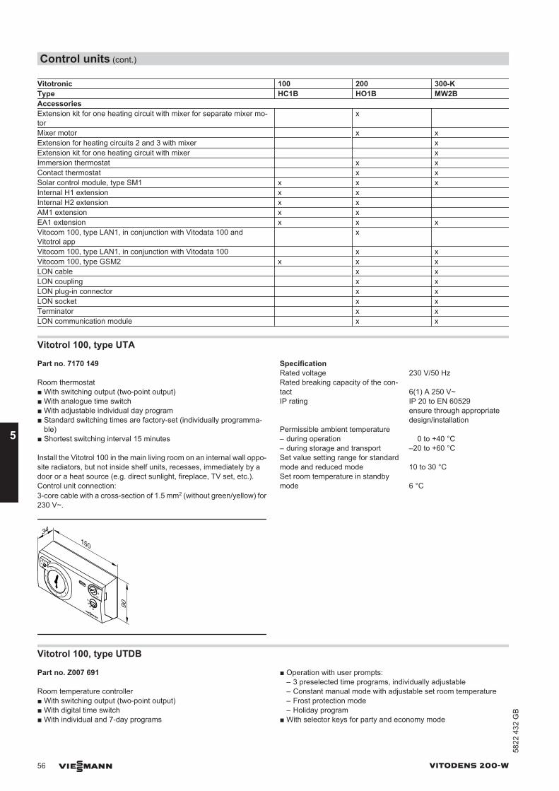
Vitotronic 100 200 300-KType HC1B HO1B MW2BAccessoriesExtension kit for one heating circuit with mixer for separate mixer mo-tor
x
Mixer motor x xExtension for heating circuits 2 and 3 with mixer xExtension kit for one heating circuit with mixer xImmersion thermostat x xContact thermostat x xSolar control module, type SM1 x x xInternal H1 extension x x Internal H2 extension x x AM1 extension x x EA1 extension x x xVitocom 100, type LAN1, in conjunction with Vitodata 100 andVitotrol app
x
Vitocom 100, type LAN1, in conjunction with Vitodata 100 x xVitocom 100, type GSM2 x x xLON cable x xLON coupling x xLON plug-in connector x xLON socket x xTerminator x xLON communication module x x
Vitotrol 100, type UTA
Part no. 7170 149
Room thermostat■ With switching output (two-point output)■ With analogue time switch■ With adjustable individual day program■ Standard switching times are factory-set (individually programma-
ble)■ Shortest switching interval 15 minutes
Install the Vitotrol 100 in the main living room on an internal wall oppo-site radiators, but not inside shelf units, recesses, immediately by adoor or a heat source (e.g. direct sunlight, fireplace, TV set, etc.).Control unit connection:3-core cable with a cross-section of 1.5 mm2 (without green/yellow) for230 V~.
150
34
90
SpecificationRated voltage 230 V/50 HzRated breaking capacity of the con-tact 6(1) A 250 V~IP rating IP 20 to EN 60529
ensure through appropriatedesign/installation
Permissible ambient temperature – during operation 0 to +40 °C– during storage and transport –20 to +60 °CSet value setting range for standardmode and reduced mode 10 to 30 °CSet room temperature in standbymode 6 °C
Vitotrol 100, type UTDB
Part no. Z007 691
Room temperature controller■ With switching output (two-point output)■ With digital time switch■ With individual and 7-day programs
■ Operation with user prompts:– 3 preselected time programs, individually adjustable– Constant manual mode with adjustable set room temperature– Frost protection mode– Holiday program
■ With selector keys for party and economy mode
Control units (cont.)
56 VIESMANN VITODENS 200-W
5
5822
432
GB
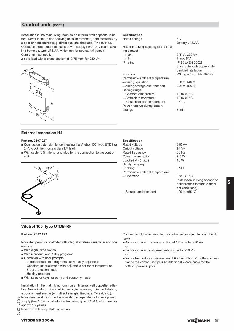
Installation in the main living room on an internal wall opposite radia-tors. Never install inside shelving units, in recesses, or immediately bya door or heat source (e.g. direct sunlight, fireplace, TV set, etc.).Operation independent of mains power supply (two 1.5 V round alka-line batteries, type LR6/AA, which run for approx.1.5 years).Control unit connection:2-core lead with a cross-section of 0.75 mm2 for 230 V~.
29
130
80
SpecificationRated voltage 3 V–
Battery LR6/AARated breaking capacity of the float-ing contact
– max. 6(1) A, 230 V~– min. 1 mA, 5 V–IP rating IP 20 to EN 60529
ensure through appropriatedesign/installation
Function RS Type 1B to EN 60730-1Permissible ambient temperature – during operation 0 to +40 °C– during storage and transport –25 to +65 °CSetting range – Comfort temperature 10 to 40 °C– Setback temperature 10 to 40 °C– Frost protection temperature 5 °CPower reserve during batterychange 3 min
External extension H4
Part no. 7197 227■ Connection extension for connecting the Vitotrol 100, type UTDB or
24 V clock thermostats via a LV lead■ With cable (0.5 m long) and plug for the connection to the control
unit
72 130
45
SpecificationRated voltage 230 V~Output voltage 24 V~Rated frequency 50 HzPower consumption 2.5 WLoad 24 V~ (max.) 10 WSafety category IIP rating IP 41Permissible ambient temperature – Operation 0 to +40 °C
Installation in living spaces orboiler rooms (standard ambi-ent conditions)
– Storage and transport –20 to +65 °C
Vitotrol 100, type UTDB-RF
Part no. Z007 692
Room temperature controller with integral wireless transmitter and onereceiver■ With digital time switch■ With individual and 7-day programs■ Operation with user prompts:
– 3 preselected time programs, individually adjustable– Constant manual mode with adjustable set room temperature– Frost protection mode– Holiday program
■ With selector keys for party and economy mode
Installation in the main living room on an internal wall opposite radia-tors. Never install inside shelving units, in recesses, or immediately bya door or heat source (e.g. direct sunlight, fireplace, TV set, etc.).Room temperature controller operation independent of mains powersupply (two 1.5 V round alkaline batteries, type LR6/AA, which run forapprox.1.5 years).Receiver with relay state indication.
Connection of the receiver to the control unit (subject to control unittype):■ 4-core cable with a cross-section of 1.5 mm2 for 230 V~
or■ 3-core cable without green/yellow core for 230 V~
or■ 2-core lead with a cross-section of 0.75 mm2 for LV for the connec-
tion to the control unit, plus an additional 2-core cable for the230 V~ power supply
Control units (cont.)
VITODENS 200-W VIESMANN 57
5822
432
GB
5
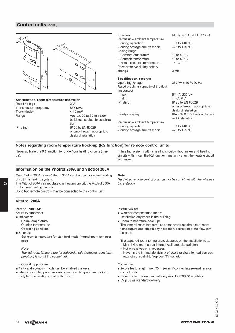
130
29
130
30
8080
Specification, room temperature controllerRated voltage 3 V–Transmission frequency 868 MHzTransmission < 10 mWRange Approx. 25 to 30 m inside
buildings, subject to construc-tion
IP rating IP 20 to EN 60529ensure through appropriatedesign/installation
Function RS Type 1B to EN 60730-1Permissible ambient temperature – during operation 0 to +40 °C– during storage and transport –25 to +65 °CSetting range – Comfort temperature 10 to 40 °C– Setback temperature 10 to 40 °C– Frost protection temperature 5 °CPower reserve during batterychange 3 min
Specification, receiverOperating voltage 230 V~ ± 10 % 50 HzRated breaking capacity of the float-ing contact
– max. 6(1) A, 230 V~– min. 1 mA, 5 V–IP rating IP 20 to EN 60529
ensure through appropriatedesign/installation
Safety category II to EN 60730-1 subject to cor-rect installation
Permissible ambient temperature – during operation 0 to +40 °C– during storage and transport –25 to +65 °C
Notes regarding room temperature hook-up (RS function) for remote control unitsNever activate the RS function for underfloor heating circuits (iner-tia).
In heating systems with a heating circuit without mixer and heatingcircuits with mixer, the RS function must only affect the heating circuitwith mixer.
Information on the Vitotrol 200A and Vitotrol 300AOne Vitotrol 200A or one Vitotrol 300A can be used for every heatingcircuit in a heating system.The Vitotrol 200A can regulate one heating circuit; the Vitotrol 300Aup to three heating circuits.Up to two remote controls may be connected to the control unit.
NoteHardwired remote control units cannot be combined with the wirelessbase station.
Vitotrol 200A
Part no. Z008 341KM BUS subscriber■ Indicators:
– Room temperature– Outside temperature– Operating condition
■ Settings:– Set room temperature for standard mode (normal room tempera-
ture)
NoteThe set room temperature for reduced mode (reduced room tem-perature) is set at the control unit.
– Operating program■ Party and economy mode can be enabled via keys■ Integral room temperature sensor for room temperature hook-up
(only for one heating circuit with mixer)
Installation site:■ Weather-compensated mode:
Installation anywhere in the building■ Room temperature hook-up:
The integral room temperature sensor captures the actual roomtemperature and effects any necessary correction of the flow tem-perature.
The captured room temperature depends on the installation site:– Main living room on an internal wall opposite radiators– Not on shelves or in recesses– Never in the immediate vicinity of doors or close to heat sources
(e.g. direct sunlight, fireplace, TV set, etc.)
Connection:■ 2-core lead, length max. 50 m (even if connecting several remote
control units)■ Never route this lead immediately next to 230/400 V cables■ LV plug as standard delivery
Control units (cont.)
58 VIESMANN VITODENS 200-W
5
5822
432
GB
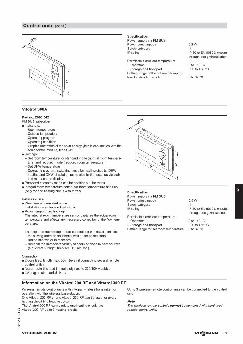
148
20,5
97
SpecificationPower supply via KM BUSPower consumption 0.2 WSafety category IIIIP rating IP 30 to EN 60529; ensure
through design/installationPermissible ambient temperature– Operation 0 to +40 °C– Storage and transport −20 to +65 °CSetting range of the set room tempera-ture for standard mode 3 to 37 °C
Vitotrol 300A
Part no. Z008 342KM BUS subscriber■ Indicators:
– Room temperature– Outside temperature– Operating program– Operating condition– Graphic illustration of the solar energy yield in conjunction with the
solar control module, type SM1■ Settings:
– Set room temperature for standard mode (normal room tempera-ture) and reduced mode (reduced room temperature)
– Set DHW temperature– Operating program, switching times for heating circuits, DHW
heating and DHW circulation pump plus further settings via plaintext menu on the display
■ Party and economy mode can be enabled via the menu■ Integral room temperature sensor for room temperature hook-up
(only for one heating circuit with mixer)
Installation site:■ Weather-compensated mode:
Installation anywhere in the building■ Room temperature hook-up:
The integral room temperature sensor captures the actual roomtemperature and effects any necessary correction of the flow tem-perature.
The captured room temperature depends on the installation site:– Main living room on an internal wall opposite radiators– Not on shelves or in recesses– Never in the immediate vicinity of doors or close to heat sources
(e.g. direct sunlight, fireplace, TV set, etc.)
Connection:■ 2-core lead, length max. 50 m (even if connecting several remote
control units)■ Never route this lead immediately next to 230/400 V cables■ LV plug as standard delivery
20,5
155 97
SpecificationPower supply via KM BUSPower consumption 0.5 WSafety category IIIIP rating IP 30 to EN 60529; ensure
through design/installationPermissible ambient temperature– Operation 0 to +40 °C– Storage and transport −20 to +65 °CSetting range for set room temperature 3 to 37 °C
Information on the Vitotrol 200 RF and Vitotrol 300 RFWireless remote control units with integral wireless transmitter foroperation with the wireless base station.One Vitotrol 200 RF or one Vitotrol 300 RF can be used for everyheating circuit in a heating system.The Vitotrol 200 RF can regulate one heating circuit; theVitotrol 300 RF up to 3 heating circuits.
Up to 3 wireless remote control units can be connected to the controlunit.
NoteThe wireless remote controls cannot be combined with hardwiredremote control units.
Control units (cont.)
VITODENS 200-W VIESMANN 59
5822
432
GB
5
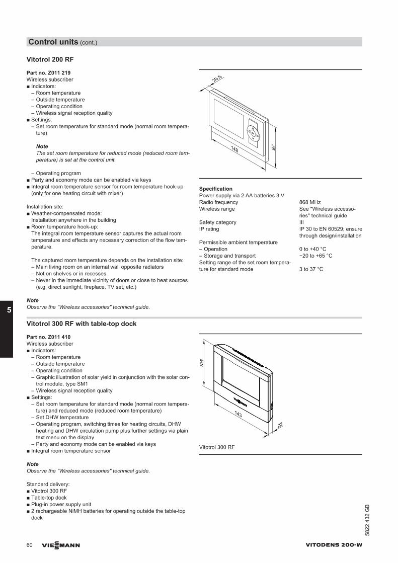
Vitotrol 200 RF
Part no. Z011 219Wireless subscriber■ Indicators:
– Room temperature– Outside temperature– Operating condition– Wireless signal reception quality
■ Settings:– Set room temperature for standard mode (normal room tempera-
ture)
NoteThe set room temperature for reduced mode (reduced room tem-perature) is set at the control unit.
– Operating program■ Party and economy mode can be enabled via keys■ Integral room temperature sensor for room temperature hook-up
(only for one heating circuit with mixer)
Installation site:■ Weather-compensated mode:
Installation anywhere in the building■ Room temperature hook-up:
The integral room temperature sensor captures the actual roomtemperature and effects any necessary correction of the flow tem-perature.
The captured room temperature depends on the installation site:– Main living room on an internal wall opposite radiators– Not on shelves or in recesses– Never in the immediate vicinity of doors or close to heat sources
(e.g. direct sunlight, fireplace, TV set, etc.)
NoteObserve the "Wireless accessories" technical guide.
148
20,5
97
SpecificationPower supply via 2 AA batteries 3 VRadio frequency 868 MHzWireless range See "Wireless accesso-
ries" technical guideSafety category IIIIP rating IP 30 to EN 60529; ensure
through design/installationPermissible ambient temperature– Operation 0 to +40 °C– Storage and transport −20 to +65 °CSetting range of the set room tempera-ture for standard mode 3 to 37 °C
Vitotrol 300 RF with table-top dock
Part no. Z011 410Wireless subscriber■ Indicators:
– Room temperature– Outside temperature– Operating condition– Graphic illustration of solar yield in conjunction with the solar con-
trol module, type SM1– Wireless signal reception quality
■ Settings:– Set room temperature for standard mode (normal room tempera-
ture) and reduced mode (reduced room temperature)– Set DHW temperature– Operating program, switching times for heating circuits, DHW
heating and DHW circulation pump plus further settings via plaintext menu on the display
– Party and economy mode can be enabled via keys■ Integral room temperature sensor
NoteObserve the "Wireless accessories" technical guide.
Standard delivery:■ Vitotrol 300 RF■ Table-top dock■ Plug-in power supply unit■ 2 rechargeable NiMH batteries for operating outside the table-top
dock
143
22
105
Vitotrol 300 RF
Control units (cont.)
60 VIESMANN VITODENS 200-W
5
5822
432
GB
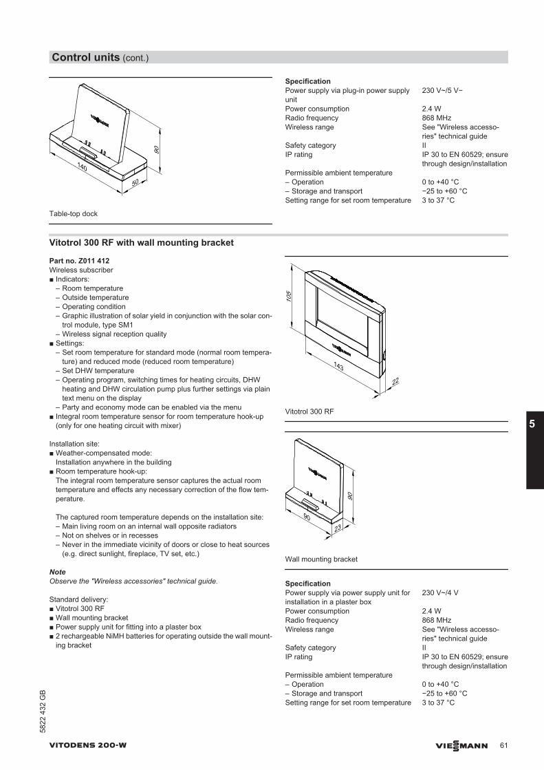
140
50
90
Table-top dock
SpecificationPower supply via plug-in power supplyunit
230 V~/5 V−
Power consumption 2.4 WRadio frequency 868 MHzWireless range See "Wireless accesso-
ries" technical guideSafety category IIIP rating IP 30 to EN 60529; ensure
through design/installationPermissible ambient temperature– Operation 0 to +40 °C– Storage and transport −25 to +60 °CSetting range for set room temperature 3 to 37 °C
Vitotrol 300 RF with wall mounting bracket
Part no. Z011 412Wireless subscriber■ Indicators:
– Room temperature– Outside temperature– Operating condition– Graphic illustration of solar yield in conjunction with the solar con-
trol module, type SM1– Wireless signal reception quality
■ Settings:– Set room temperature for standard mode (normal room tempera-
ture) and reduced mode (reduced room temperature)– Set DHW temperature– Operating program, switching times for heating circuits, DHW
heating and DHW circulation pump plus further settings via plaintext menu on the display
– Party and economy mode can be enabled via the menu■ Integral room temperature sensor for room temperature hook-up
(only for one heating circuit with mixer)
Installation site:■ Weather-compensated mode:
Installation anywhere in the building■ Room temperature hook-up:
The integral room temperature sensor captures the actual roomtemperature and effects any necessary correction of the flow tem-perature.
The captured room temperature depends on the installation site:– Main living room on an internal wall opposite radiators– Not on shelves or in recesses– Never in the immediate vicinity of doors or close to heat sources
(e.g. direct sunlight, fireplace, TV set, etc.)
NoteObserve the "Wireless accessories" technical guide.
Standard delivery:■ Vitotrol 300 RF■ Wall mounting bracket■ Power supply unit for fitting into a plaster box■ 2 rechargeable NiMH batteries for operating outside the wall mount-
ing bracket
143
22
105
Vitotrol 300 RF
23
90
90
Wall mounting bracket
SpecificationPower supply via power supply unit forinstallation in a plaster box
230 V~/4 V
Power consumption 2.4 WRadio frequency 868 MHzWireless range See "Wireless accesso-
ries" technical guideSafety category IIIP rating IP 30 to EN 60529; ensure
through design/installationPermissible ambient temperature– Operation 0 to +40 °C– Storage and transport −25 to +60 °CSetting range for set room temperature 3 to 37 °C
Control units (cont.)
VITODENS 200-W VIESMANN 61
5822
432
GB
5
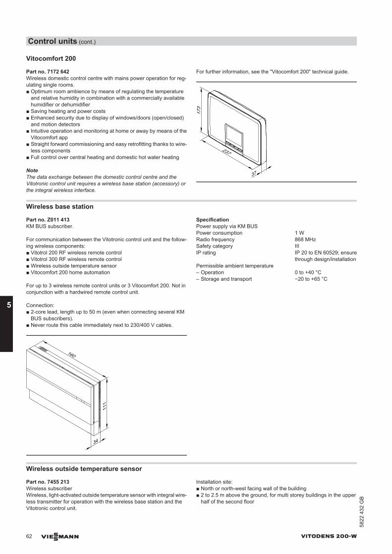
Vitocomfort 200
Part no. 7172 642Wireless domestic control centre with mains power operation for reg-ulating single rooms.■ Optimum room ambience by means of regulating the temperature
and relative humidity in combination with a commercially availablehumidifier or dehumidifier
■ Saving heating and power costs■ Enhanced security due to display of windows/doors (open/closed)
and motion detectors■ Intuitive operation and monitoring at home or away by means of the
Vitocomfort app■ Straight forward commissioning and easy retrofitting thanks to wire-
less components■ Full control over central heating and domestic hot water heating
NoteThe data exchange between the domestic control centre and theVitotronic control unit requires a wireless base station (accessory) orthe integral wireless interface.
For further information, see the "Vitocomfort 200" technical guide.
37
237
173
Wireless base station
Part no. Z011 413KM BUS subscriber.
For communication between the Vitotronic control unit and the follow-ing wireless components:■ Vitotrol 200 RF wireless remote control■ Vitotrol 300 RF wireless remote control■ Wireless outside temperature sensor■ Vitocomfort 200 home automation
For up to 3 wireless remote control units or 3 Vitocomfort 200. Not inconjunction with a hardwired remote control unit.
Connection:■ 2-core lead, length up to 50 m (even when connecting several KM
BUS subscribers).■ Never route this cable immediately next to 230/400 V cables.
160
34
111
SpecificationPower supply via KM BUSPower consumption 1 WRadio frequency 868 MHzSafety category IIIIP rating IP 20 to EN 60529; ensure
through design/installationPermissible ambient temperature– Operation 0 to +40 °C– Storage and transport −20 to +65 °C
Wireless outside temperature sensor
Part no. 7455 213Wireless subscriberWireless, light-activated outside temperature sensor with integral wire-less transmitter for operation with the wireless base station and theVitotronic control unit.
Installation site:■ North or north-west facing wall of the building■ 2 to 2.5 m above the ground, for multi storey buildings in the upper
half of the second floor
Control units (cont.)
62 VIESMANN VITODENS 200-W
5
5822
432
GB
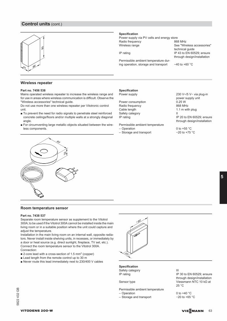
41 66
80
SpecificationPower supply via PV cells and energy storeRadio frequency 868 MHzWireless range See "Wireless accessories"
technical guideIP rating IP 43 to EN 60529; ensure
through design/installationPermissible ambient temperature dur-ing operation, storage and transport −40 to +60 °C
Wireless repeater
Part no. 7456 538Mains operated wireless repeater to increase the wireless range andfor use in areas where wireless communication is difficult. Observe the"Wireless accessories" technical guide.Do not use more than one wireless repeater per Vitotronic controlunit.■ To prevent the need for radio signals to penetrate steel reinforced
concrete ceilings/floors and/or multiple walls at a strongly diagonalangle.
■ For circumventing large metallic objects situated between the wire-less components.
93
32
SpecificationPower supply 230 V~/5 V− via plug-in
power supply unitPower consumption 0.25 WRadio frequency 868 MHzCable length 1.1 m with plugSafety category IIIP rating IP 20 to EN 60529; ensure
through design/installationPermissible ambient temperature– Operation 0 to +55 °C– Storage and transport −20 to +75 °C
Room temperature sensor
Part no. 7438 537Separate room temperature sensor as supplement to the Vitotrol300A; to be used if the Vitotrol 300A cannot be installed inside the mainliving room or in a suitable position where the unit could capture andadjust the temperature.Installation in the main living room on an internal wall, opposite radia-tors. Never install inside shelving units, in recesses, or immediately bya door or heat source (e.g. direct sunlight, fireplace, TV set, etc.).Connect the room temperature sensor to the Vitotrol 300A.Connection:■ 2-core lead with a cross-section of 1.5 mm2 (copper)■ Lead length from the remote control up to 30 m■ Never route this lead immediately next to 230/400 V cables
20
80□
SpecificationSafety category IIIIP rating IP 30 to EN 60529; ensure
through design/installationSensor type Viessmann NTC 10 kΩ at
25 °CPermissible ambient temperature– Operation 0 to +40 °C– Storage and transport −20 to +65 °C
Control units (cont.)
VITODENS 200-W VIESMANN 63
5822
432
GB
5
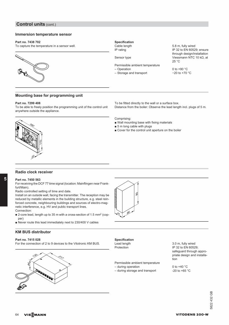
Immersion temperature sensor
Part no. 7438 702To capture the temperature in a sensor well.
SpecificationCable length 5.8 m, fully wiredIP rating IP 32 to EN 60529; ensure
through design/installationSensor type Viessmann NTC 10 kΩ, at
25 °CPermissible ambient temperature– Operation 0 to +90 °C– Storage and transport −20 to +70 °C
Mounting base for programming unit
Part no. 7299 408To be able to freely position the programming unit of the control unitanywhere outside the appliance.
To be fitted directly to the wall or a surface box.Distance from the boiler: Observe the lead length incl. plugs of 5 m.
20
160
110
Comprising:■ Wall mounting base with fixing materials■ 5 m long cable with plugs■ Cover for the control unit aperture on the boiler
Radio clock receiver
Part no. 7450 563For receiving the DCF 77 time signal (location: Mainflingen near Frank-furt/Main).Radio controlled setting of time and date.Install on an outside wall, facing the transmitter. The reception may bereduced by metallic elements in the building structure, e.g. steel rein-forced concrete, neighbouring buildings and sources of electro-mag-netic interference, e.g. HV and public transport lines.Connection:■ 2-core lead, length up to 35 m with a cross-section of 1.5 mm2 (cop-
per)■ Never route this lead immediately next to 230/400 V cables
41 66
80
KM BUS distributor
Part no. 7415 028For the connection of 2 to 9 devices to the Vitotronic KM BUS.
217130
84
SpecificationLead length 3.0 m, fully wiredProtection IP 32 to EN 60529;
safeguard through appro-priate design and installa-tion
Permissible ambient temperature– during operation 0 to +40 °C– during storage and transport -20 to +65 °C
Control units (cont.)
64 VIESMANN VITODENS 200-W
5
5822
432
GB
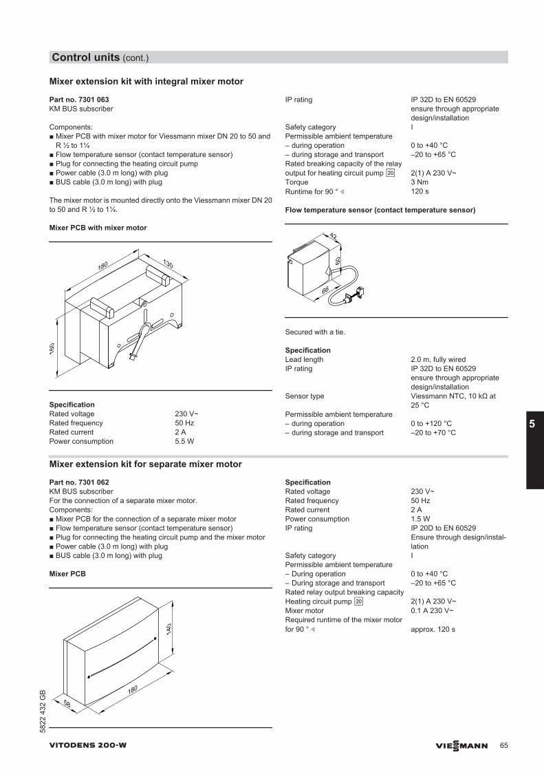
Mixer extension kit with integral mixer motor
Part no. 7301 063KM BUS subscriber
Components:■ Mixer PCB with mixer motor for Viessmann mixer DN 20 to 50 and
R ½ to 1¼■ Flow temperature sensor (contact temperature sensor)■ Plug for connecting the heating circuit pump■ Power cable (3.0 m long) with plug■ BUS cable (3.0 m long) with plug
The mixer motor is mounted directly onto the Viessmann mixer DN 20to 50 and R ½ to 1¼.
Mixer PCB with mixer motor
160
180 130
SpecificationRated voltage 230 V~Rated frequency 50 HzRated current 2 APower consumption 5.5 W
IP rating IP 32D to EN 60529ensure through appropriatedesign/installation
Safety category IPermissible ambient temperature – during operation 0 to +40 °C– during storage and transport –20 to +65 °CRated breaking capacity of the relayoutput for heating circuit pump sÖ 2(1) A 230 V~Torque 3 NmRuntime for 90 ° ∢ 120 s
Flow temperature sensor (contact temperature sensor)
42
66
60Secured with a tie.
SpecificationLead length 2.0 m, fully wiredIP rating IP 32D to EN 60529
ensure through appropriatedesign/installation
Sensor type Viessmann NTC, 10 kΩ at25 °C
Permissible ambient temperature – during operation 0 to +120 °C– during storage and transport –20 to +70 °C
Mixer extension kit for separate mixer motor
Part no. 7301 062KM BUS subscriberFor the connection of a separate mixer motor.Components:■ Mixer PCB for the connection of a separate mixer motor■ Flow temperature sensor (contact temperature sensor)■ Plug for connecting the heating circuit pump and the mixer motor■ Power cable (3.0 m long) with plug■ BUS cable (3.0 m long) with plug
Mixer PCB
58180
140
SpecificationRated voltage 230 V~Rated frequency 50 HzRated current 2 APower consumption 1.5 WIP rating IP 20D to EN 60529
Ensure through design/instal-lation
Safety category IPermissible ambient temperature – During operation 0 to +40 °C– During storage and transport –20 to +65 °CRated relay output breaking capacity Heating circuit pump sÖ 2(1) A 230 V~Mixer motor 0.1 A 230 V~Required runtime of the mixer motorfor 90 ° ∢ approx. 120 s
Control units (cont.)
VITODENS 200-W VIESMANN 65
5822
432
GB
5
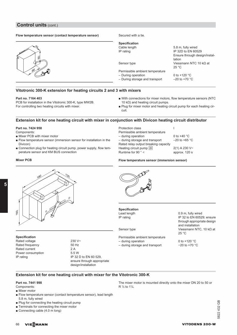
Flow temperature sensor (contact temperature sensor)
42
66
60Secured with a tie.
SpecificationCable length 5.8 m, fully wiredIP rating IP 32D to EN 60529
Ensure through design/instal-lation
Sensor type Viessmann NTC 10 kΩ at25 °C
Permissible ambient temperature – During operation 0 to +120 °C– During storage and transport –20 to +70 °C
Vitotronic 300-K extension for heating circuits 2 and 3 with mixers
Part no. 7164 403PCB for installation in the Vitotronic 300-K, type MW2B.For controlling two heating circuits with mixer.
■ With connections for mixer motors, flow temperature sensors (NTC10 kΩ) and heating circuit pumps.
■ Plug for mixer motor and heating circuit pump for each heating cir-cuit.
Extension kit for one heating circuit with mixer in conjunction with Divicon heating circuit distributor
Part no. 7424 958Components:■ Mixer PCB with mixer motor■ Flow temperature sensor (immersion sensor for installation in the
Divicon)■ Connection plug for heating circuit pump, power supply, flow tem-
perature sensor and KM BUS connection
Mixer PCB
160
180 130
SpecificationRated voltage 230 V~Rated frequency 50 HzRated current 2 APower consumption 5.5 WIP rating IP 32 D to EN 60 529,
ensure through appropriatedesign/installation
Protection class IPermissible ambient temperature – during operation 0 to +40 °C– during storage and transport –20 to +65 °CRated relay output breaking capacity Heating circuit pump sÖ 2(1) A 230 V~Runtime for 90 ° ∢ approx. 120 s
Flow temperature sensor (immersion sensor)
SpecificationLead length 0.9 m, fully wiredIP rating IP 32 to EN 60529; ensure
through appropriate designand installation
Sensor type Viessmann NTC, 10 kΩ at25 °C
Permissible ambient temperature – during operation 0 to +120 °C– during storage and transport −20 to +70 °C
Extension kit for one heating circuit with mixer for the Vitotronic 300-K
Part no. 7441 998Components:■ Mixer motor■ Flow temperature sensor (contact temperature sensor), lead length
5.8 m, fully wired■ Plug for connecting the heating circuit pump■ Terminals for connecting the mixer motor■ Connecting cable (4.0 m long)
The mixer motor is mounted directly onto the mixer DN 20 to 50 orR ½ to 1¼.
Control units (cont.)
66 VIESMANN VITODENS 200-W
5
5822
432
GB
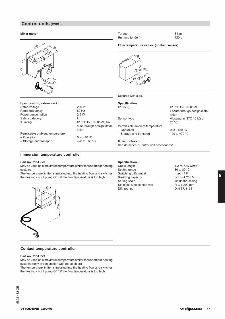
Mixer motor
180
130
90
Specification, extension kitRated voltage 230 V~Rated frequency 50 HzPower consumption 2.5 WSafety category IIP rating IP 32D to EN 60529; en-
sure through design/instal-lation
Permissible ambient temperature – Operation 0 to +40 °C– Storage and transport –20 to +65 °C
Torque 3 NmRuntime for 90 ° ∢ 120 s
Flow temperature sensor (contact sensor)
42
66
60
Secured with a tie.
SpecificationIP rating IP 32D to EN 60529
Ensure through design/instal-lation
Sensor type Viessmann NTC 10 kΩ at25 °C
Permissible ambient temperature – Operation 0 to +120 °C– Storage and transport –20 to +70 °C
Mixer motorsSee datasheet "Control unit accessories".
Immersion temperature controller
Part no. 7151 728May be used as a maximum temperature limiter for underfloor heatingsystems.The temperature limiter is installed into the heating flow and switchesthe heating circuit pump OFF if the flow temperature is too high.
72 130
9520
0
SpecificationCable length 4.2 m, fully wiredSetting range 30 to 80 °CSwitching differential max. 11 KBreaking capacity 6(1.5) A 250 V~Setting scale inside the casingStainless steel sensor well R ½ x 200 mmDIN reg. no. DIN TR 1168
Contact temperature controller
Part no. 7151 729May be used as a maximum temperature limiter for underfloor heatingsystems (only in conjunction with metal pipes).The temperature limiter is installed into the heating flow and switchesthe heating circuit pump OFF if the flow temperature is too high.
Control units (cont.)
VITODENS 200-W VIESMANN 67
5822
432
GB
5
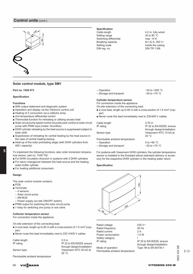
72 130
95
SpecificationCable length 4.2 m, fully wiredSetting range 30 to 80 °CSwitching differential max. 14 KBreaking capacity 6(1.5) A, 250 V~Setting scale inside the casingDIN reg. no. DIN TR 1168
Solar control module, type SM1
Part no. 7429 073
Specification
Functions■ With output statement and diagnostic system■ Operation and display via the Vitotronic control unit■ Heating of 2 consumers via a collector array■ 2nd temperature differential control■ Thermostat function for reheating or utilising excess heat■ Solar circuit pump speed control via pulse pack control or solar circuit
pump with PWM input (make: Grundfos)■ DHW cylinder reheating by the heat source is suppressed subject to
solar yield.■ Suppression of reheating for central heating by the heat source in
the case of central heating backup■ Heat-up of the solar preheating stage (with DHW cylinders from
400 l capacity)
To implement the following functions, also order immersion tempera-ture sensor, part no. 7438 702:■ For DHW circulation diversion in systems with 2 DHW cylinders■ For return changeover between the heat source and the heating
water buffer cylinder■ For heating additional consumers
Design
The solar control module contains:■ PCB■ Terminals:
– 4 sensors– Solar circuit pump– KM BUS– Power supply (on-site ON/OFF switch)
■ PWM output for switching the solar circuit pump■ 1 relay for switching one pump or one valve
Collector temperature sensorFor connection inside the appliance
On-site extension of the connecting lead:■ 2-core lead, length up to 60 m with a cross-section of 1.5 mm2 (cop-
per)■ Never route this lead immediately next to 230 V/400 V cables
Cable length 2.5 mIP rating IP 32 to EN 60529; ensure
through design/installationSensor type Viessmann NTC 20 kΩ at
25 °CPermissible ambient temperature
– Operation −20 to +200 °C– Storage and transport −20 to +70 °C
Cylinder temperature sensorFor connection inside the applianceOn-site extension of the connecting lead:■ 2-core lead, length up to 60 m with a cross-section of 1.5 mm2 (cop-
per)■ Never route this lead immediately next to 230/400 V cables
Cable length 3.75 mIP rating IP 32 to EN 60529; ensure
through design/installationSensor type Viessmann NTC 10 kΩ at
25 °CPermissible ambient temperature– Operation 0 to +90 °C– Storage and transport −20 to +70 °C
For systems with Viessmann DHW cylinders, the cylinder temperaturesensor is installed in the threaded elbow (standard delivery or acces-sory for the respective DHW cylinder) in the heating water return.
Specification
58180
140
Rated voltage 230 V~Rated frequency 50 HzRated current 2 APower consumption 1.5 WSafety category IIP rating IP 20 to EN 60529; ensure
through design/installationMode of operation Type 1B to EN 60730-1Permissible ambient temperature
Control units (cont.)
68 VIESMANN VITODENS 200-W
5
5822
432
GB
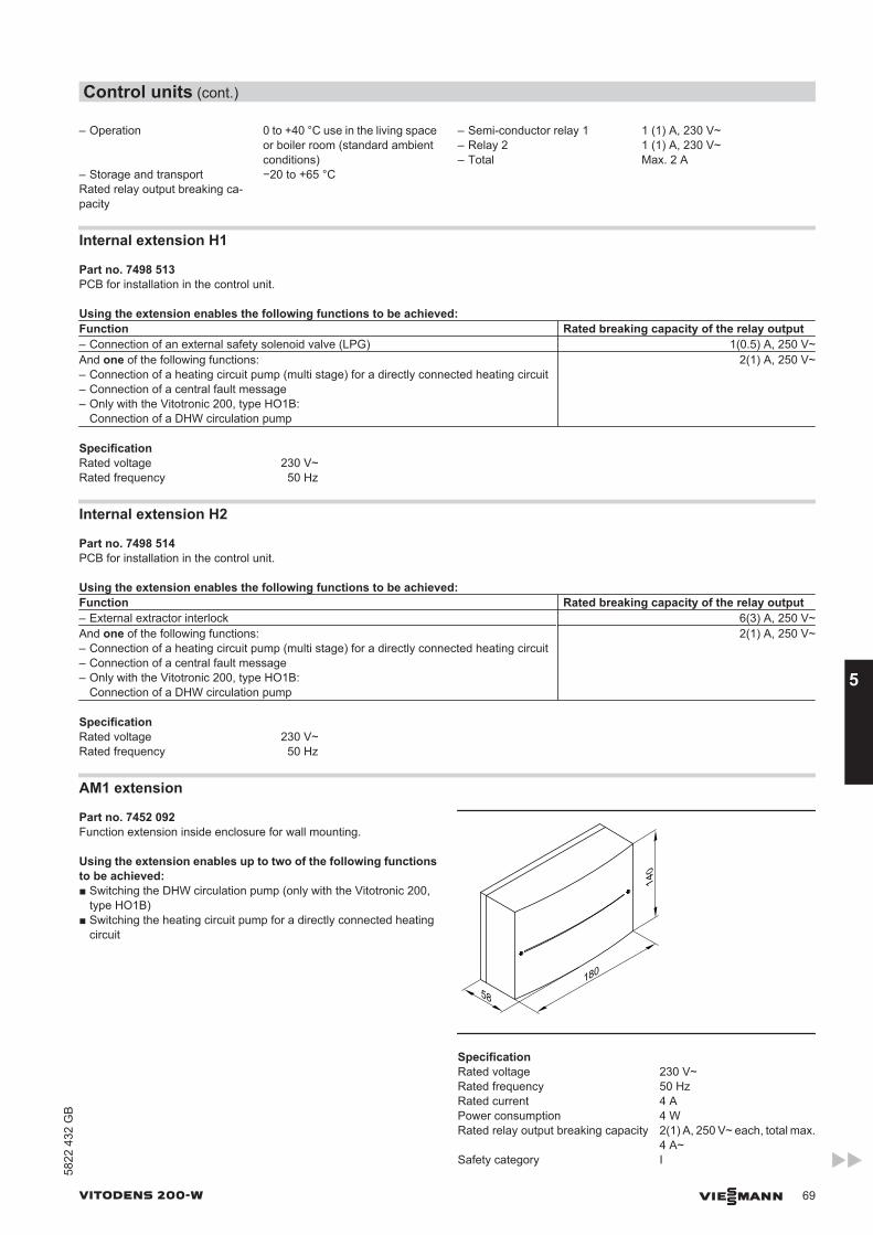
– Operation 0 to +40 °C use in the living spaceor boiler room (standard ambientconditions)
– Storage and transport −20 to +65 °CRated relay output breaking ca-pacity
– Semi-conductor relay 1 1 (1) A, 230 V~– Relay 2 1 (1) A, 230 V~– Total Max. 2 A
Internal extension H1
Part no. 7498 513PCB for installation in the control unit.
Using the extension enables the following functions to be achieved:Function Rated breaking capacity of the relay output– Connection of an external safety solenoid valve (LPG) 1(0.5) A, 250 V~And one of the following functions:– Connection of a heating circuit pump (multi stage) for a directly connected heating circuit– Connection of a central fault message– Only with the Vitotronic 200, type HO1B:
Connection of a DHW circulation pump
2(1) A, 250 V~
SpecificationRated voltage 230 V~Rated frequency 50 Hz
Internal extension H2
Part no. 7498 514PCB for installation in the control unit.
Using the extension enables the following functions to be achieved:Function Rated breaking capacity of the relay output– External extractor interlock 6(3) A, 250 V~And one of the following functions:– Connection of a heating circuit pump (multi stage) for a directly connected heating circuit– Connection of a central fault message– Only with the Vitotronic 200, type HO1B:
Connection of a DHW circulation pump
2(1) A, 250 V~
SpecificationRated voltage 230 V~Rated frequency 50 Hz
AM1 extension
Part no. 7452 092Function extension inside enclosure for wall mounting.
Using the extension enables up to two of the following functionsto be achieved:■ Switching the DHW circulation pump (only with the Vitotronic 200,
type HO1B)■ Switching the heating circuit pump for a directly connected heating
circuit
58180
140
SpecificationRated voltage 230 V~Rated frequency 50 HzRated current 4 APower consumption 4 WRated relay output breaking capacity 2(1) A, 250 V~ each, total max.
4 A~Safety category I
Control units (cont.)
VITODENS 200-W VIESMANN 69
5822
432
GB
5
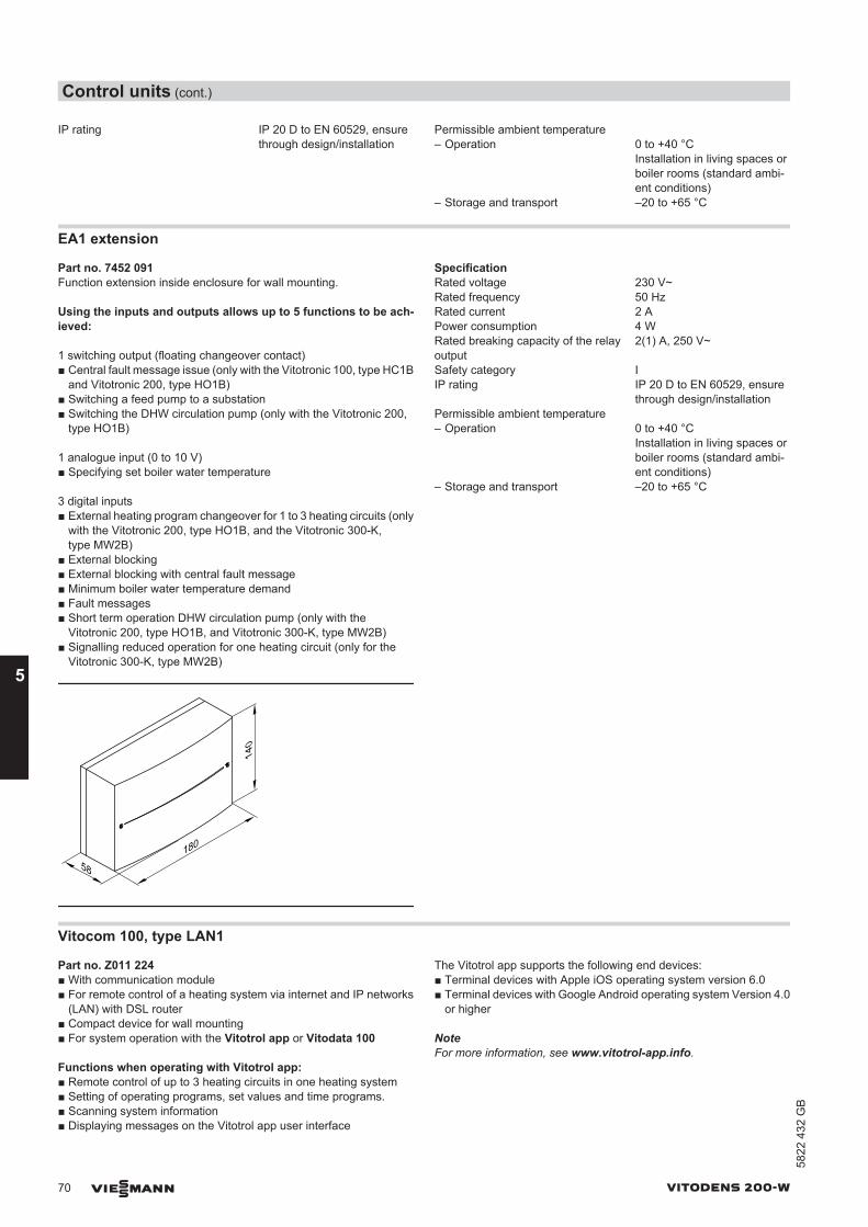
IP rating IP 20 D to EN 60529, ensurethrough design/installation
Permissible ambient temperature – Operation 0 to +40 °C
Installation in living spaces orboiler rooms (standard ambi-ent conditions)
– Storage and transport –20 to +65 °C
EA1 extension
Part no. 7452 091Function extension inside enclosure for wall mounting.
Using the inputs and outputs allows up to 5 functions to be ach-ieved:
1 switching output (floating changeover contact)■ Central fault message issue (only with the Vitotronic 100, type HC1B
and Vitotronic 200, type HO1B)■ Switching a feed pump to a substation■ Switching the DHW circulation pump (only with the Vitotronic 200,
type HO1B)
1 analogue input (0 to 10 V)■ Specifying set boiler water temperature
3 digital inputs■ External heating program changeover for 1 to 3 heating circuits (only
with the Vitotronic 200, type HO1B, and the Vitotronic 300-K,type MW2B)
■ External blocking■ External blocking with central fault message■ Minimum boiler water temperature demand■ Fault messages■ Short term operation DHW circulation pump (only with the
Vitotronic 200, type HO1B, and Vitotronic 300-K, type MW2B)■ Signalling reduced operation for one heating circuit (only for the
Vitotronic 300-K, type MW2B)
58180
140
SpecificationRated voltage 230 V~Rated frequency 50 HzRated current 2 APower consumption 4 WRated breaking capacity of the relayoutput
2(1) A, 250 V~
Safety category IIP rating IP 20 D to EN 60529, ensure
through design/installationPermissible ambient temperature – Operation 0 to +40 °C
Installation in living spaces orboiler rooms (standard ambi-ent conditions)
– Storage and transport –20 to +65 °C
Vitocom 100, type LAN1
Part no. Z011 224■ With communication module■ For remote control of a heating system via internet and IP networks
(LAN) with DSL router■ Compact device for wall mounting■ For system operation with the Vitotrol app or Vitodata 100
Functions when operating with Vitotrol app:■ Remote control of up to 3 heating circuits in one heating system■ Setting of operating programs, set values and time programs.■ Scanning system information■ Displaying messages on the Vitotrol app user interface
The Vitotrol app supports the following end devices:■ Terminal devices with Apple iOS operating system version 6.0■ Terminal devices with Google Android operating system Version 4.0
or higher
NoteFor more information, see www.vitotrol-app.info.
Control units (cont.)
70 VIESMANN VITODENS 200-W
5
5822
432
GB
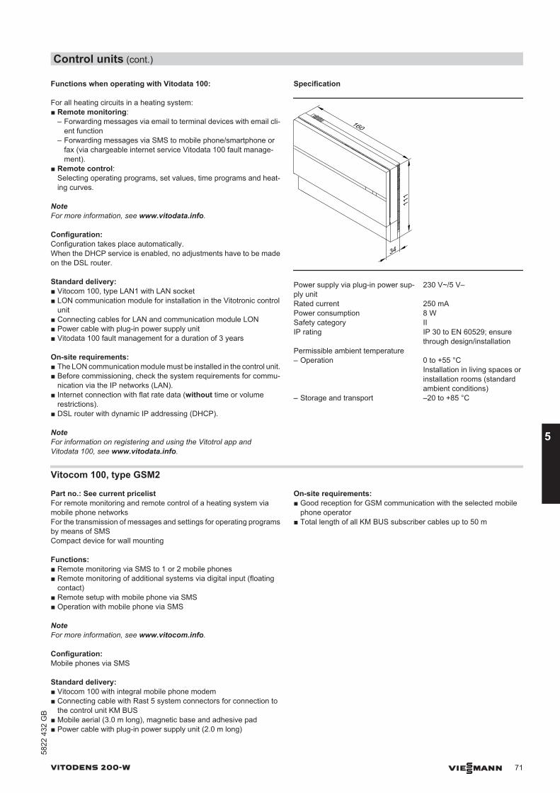
Functions when operating with Vitodata 100:
For all heating circuits in a heating system:■ Remote monitoring:
– Forwarding messages via email to terminal devices with email cli-ent function
– Forwarding messages via SMS to mobile phone/smartphone orfax (via chargeable internet service Vitodata 100 fault manage-ment).
■ Remote control:Selecting operating programs, set values, time programs and heat-ing curves.
NoteFor more information, see www.vitodata.info.
Configuration:Configuration takes place automatically.When the DHCP service is enabled, no adjustments have to be madeon the DSL router.
Standard delivery:■ Vitocom 100, type LAN1 with LAN socket■ LON communication module for installation in the Vitotronic control
unit■ Connecting cables for LAN and communication module LON■ Power cable with plug-in power supply unit■ Vitodata 100 fault management for a duration of 3 years
On-site requirements:■ The LON communication module must be installed in the control unit.■ Before commissioning, check the system requirements for commu-
nication via the IP networks (LAN).■ Internet connection with flat rate data (without time or volume
restrictions).■ DSL router with dynamic IP addressing (DHCP).
NoteFor information on registering and using the Vitotrol app andVitodata 100, see www.vitodata.info.
Specification
160
34
111
Power supply via plug-in power sup-ply unit
230 V~/5 V–
Rated current 250 mAPower consumption 8 WSafety category IIIP rating IP 30 to EN 60529; ensure
through design/installationPermissible ambient temperature – Operation 0 to +55 °C
Installation in living spaces orinstallation rooms (standardambient conditions)
– Storage and transport –20 to +85 °C
Vitocom 100, type GSM2
Part no.: See current pricelistFor remote monitoring and remote control of a heating system viamobile phone networksFor the transmission of messages and settings for operating programsby means of SMSCompact device for wall mounting
Functions:■ Remote monitoring via SMS to 1 or 2 mobile phones■ Remote monitoring of additional systems via digital input (floating
contact)■ Remote setup with mobile phone via SMS■ Operation with mobile phone via SMS
NoteFor more information, see www.vitocom.info.
Configuration:Mobile phones via SMS
Standard delivery:■ Vitocom 100 with integral mobile phone modem■ Connecting cable with Rast 5 system connectors for connection to
the control unit KM BUS■ Mobile aerial (3.0 m long), magnetic base and adhesive pad■ Power cable with plug-in power supply unit (2.0 m long)
On-site requirements:■ Good reception for GSM communication with the selected mobile
phone operator■ Total length of all KM BUS subscriber cables up to 50 m
Control units (cont.)
VITODENS 200-W VIESMANN 71
5822
432
GB
5
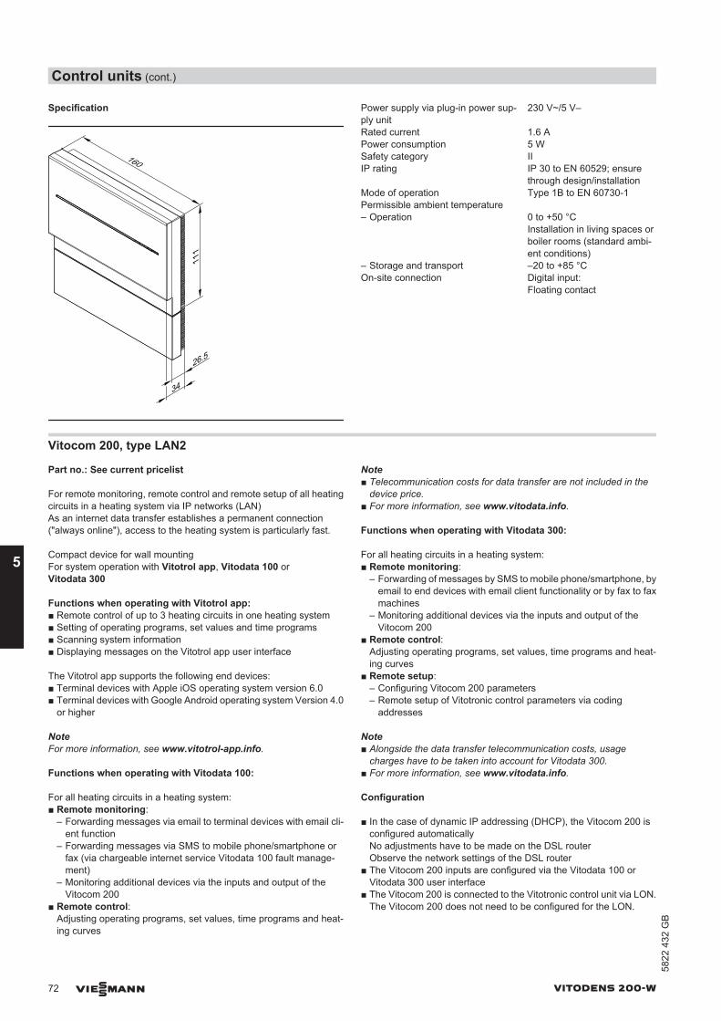
Specification
26.5
160
111
34
Power supply via plug-in power sup-ply unit
230 V~/5 V–
Rated current 1.6 APower consumption 5 WSafety category IIIP rating IP 30 to EN 60529; ensure
through design/installationMode of operation Type 1B to EN 60730-1Permissible ambient temperature – Operation 0 to +50 °C
Installation in living spaces orboiler rooms (standard ambi-ent conditions)
– Storage and transport –20 to +85 °COn-site connection Digital input:
Floating contact
Vitocom 200, type LAN2
Part no.: See current pricelist
For remote monitoring, remote control and remote setup of all heatingcircuits in a heating system via IP networks (LAN)As an internet data transfer establishes a permanent connection("always online"), access to the heating system is particularly fast.
Compact device for wall mountingFor system operation with Vitotrol app, Vitodata 100 orVitodata 300
Functions when operating with Vitotrol app:■ Remote control of up to 3 heating circuits in one heating system■ Setting of operating programs, set values and time programs■ Scanning system information■ Displaying messages on the Vitotrol app user interface
The Vitotrol app supports the following end devices:■ Terminal devices with Apple iOS operating system version 6.0■ Terminal devices with Google Android operating system Version 4.0
or higher
NoteFor more information, see www.vitotrol-app.info.
Functions when operating with Vitodata 100:
For all heating circuits in a heating system:■ Remote monitoring:
– Forwarding messages via email to terminal devices with email cli-ent function
– Forwarding messages via SMS to mobile phone/smartphone orfax (via chargeable internet service Vitodata 100 fault manage-ment)
– Monitoring additional devices via the inputs and output of theVitocom 200
■ Remote control:Adjusting operating programs, set values, time programs and heat-ing curves
Note■ Telecommunication costs for data transfer are not included in the
device price.■ For more information, see www.vitodata.info.
Functions when operating with Vitodata 300:
For all heating circuits in a heating system:■ Remote monitoring:
– Forwarding of messages by SMS to mobile phone/smartphone, byemail to end devices with email client functionality or by fax to faxmachines
– Monitoring additional devices via the inputs and output of theVitocom 200
■ Remote control:Adjusting operating programs, set values, time programs and heat-ing curves
■ Remote setup:– Configuring Vitocom 200 parameters– Remote setup of Vitotronic control parameters via coding
addresses
Note■ Alongside the data transfer telecommunication costs, usage
charges have to be taken into account for Vitodata 300.■ For more information, see www.vitodata.info.
Configuration
■ In the case of dynamic IP addressing (DHCP), the Vitocom 200 isconfigured automaticallyNo adjustments have to be made on the DSL routerObserve the network settings of the DSL router
■ The Vitocom 200 inputs are configured via the Vitodata 100 orVitodata 300 user interface
■ The Vitocom 200 is connected to the Vitotronic control unit via LON.The Vitocom 200 does not need to be configured for the LON.
Control units (cont.)
72 VIESMANN VITODENS 200-W
5
5822
432
GB
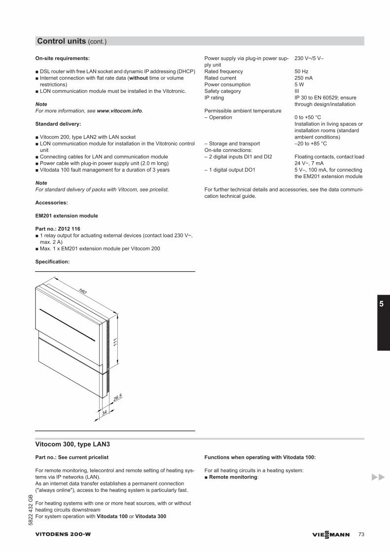
On-site requirements:
■ DSL router with free LAN socket and dynamic IP addressing (DHCP)■ Internet connection with flat rate data (without time or volume
restrictions)■ LON communication module must be installed in the Vitotronic.
NoteFor more information, see www.vitocom.info.
Standard delivery:
■ Vitocom 200, type LAN2 with LAN socket■ LON communication module for installation in the Vitotronic control
unit■ Connecting cables for LAN and communication module■ Power cable with plug-in power supply unit (2.0 m long)■ Vitodata 100 fault management for a duration of 3 years
NoteFor standard delivery of packs with Vitocom, see pricelist.
Accessories:
EM201 extension module
Part no.: Z012 116■ 1 relay output for actuating external devices (contact load 230 V~,
max. 2 A)■ Max. 1 x EM201 extension module per Vitocom 200
Specification:
26.5
160
111
34
Power supply via plug-in power sup-ply unit
230 V~/5 V–
Rated frequency 50 HzRated current 250 mAPower consumption 5 WSafety category IIIIP rating IP 30 to EN 60529; ensure
through design/installationPermissible ambient temperature – Operation 0 to +50 °C
Installation in living spaces orinstallation rooms (standardambient conditions)
– Storage and transport –20 to +85 °COn-site connections: – 2 digital inputs DI1 and DI2 Floating contacts, contact load
24 V−, 7 mA– 1 digital output DO1 5 V–, 100 mA, for connecting
the EM201 extension module
For further technical details and accessories, see the data communi-cation technical guide.
Vitocom 300, type LAN3
Part no.: See current pricelist
For remote monitoring, telecontrol and remote setting of heating sys-tems via IP networks (LAN).As an internet data transfer establishes a permanent connection("always online"), access to the heating system is particularly fast.
For heating systems with one or more heat sources, with or withoutheating circuits downstreamFor system operation with Vitodata 100 or Vitodata 300
Functions when operating with Vitodata 100:
For all heating circuits in a heating system:■ Remote monitoring:
Control units (cont.)
VITODENS 200-W VIESMANN 73
5822
432
GB
5
– Forwarding messages via email to terminal devices with email cli-ent function
– Forwarding messages via SMS to mobile phone/smartphone orfax (via chargeable internet service Vitodata 100 fault manage-ment)
– Monitoring of additional devices via the inputs and outputs of theVitocom and EM301 extension modules
■ Remote control:Selecting operating programs, set values, time programs and heat-ing curves
Note■ Telecommunication costs for data transfer are not included in the
device price.■ For more information, see www.vitodata.info.
Functions when operating with Vitodata 300:
For all heating circuits in a heating system:■ Remote monitoring:
– Forwarding of messages via SMS to mobile phone/smartphone,via email to end devices with email client functionality or via fax tofax machines
– Monitoring of additional devices via the inputs and outputs of theVitocom 300
■ Remote control:– Selecting operating programs, set values, time programs and
heating curves– Recording trends via datalogger– Recording of energy consumption through integration of M BUS
heat meters■ Remote setup:
– Configuring Vitocom 300 parameters– Remote setup of Vitotronic control parameters via coding
addresses
Note■ Alongside the data transfer telecommunication costs, usage
charges have to be taken into account for Vitodata 300.■ For more information, see www.vitodata.info.
Configuration
■ In the case of dynamic IP addressing (DHCP), the IP configurationof the Vitocom 300 occurs automatically.No adjustments have to be made on the DSL router.
■ Observe the network settings of the DSL router.■ The outputs and inputs of the Vitocom 300 and EM301 extension
module are configured using the Vitodata 300 user interface.■ The Vitocom 300 is connected to the Vitotronic control unit via LON.
The Vitocom 300 does not need to be configured for the LON.
Fault messages
Fault messages are reported to the Vitodata server. These messagesare transmitted via the following communication services from theVitodata server to the configured recipients:■ Fax■ SMS to mobile phones■ Email to PC/laptop
On-site requirements:
■ DSL router with free LAN socket and dynamic IP addressing (DHCP)■ Internet connection with flat rate data (without time or volume
restrictions)■ LON communication module must be installed in the Vitotronic appli-
ance
NoteFor more information, see www.vitocom.info.
Standard delivery:■ Vitocom 300, type LAN3 with LAN socket
– Mounting rail installation TS35 to EN 50022,35 x 15 and 35 x 7.5
– 2 digital inputs– 1 digital output– 1 relay output– 1 M BUS interface– 1 EM interface– 2 LON connections
■ LAN cable, RJ45, 2 m long■ LON communication module■ LON cable, RJ45 – RJ45, 7 m long, for data exchange between the
Vitotronic control unit and the Vitocom 300■ Power supply unit for top-hat rail, mounting rail installation TS35 to
EN 50022, 35 x 15 and 35 x 7.5■ Vitodata 100 fault management for a duration of 3 years
NoteFor standard delivery of packs with Vitocom, see pricelist.
Accessories:
Accessories Part no.Wall mounting enclosure for installation of theVitocom 300 and accessories if no control panel orelectrical distribution panel is available.
2 rows 7143 4343 rows 7143 435EM301 extension module – Mounting rail installation TS35 to EN 50022,
35 x 15 and 35 x 7.5.– 8 analogue inputs:
– 0 − 10 V–– 4 − 20 mA– Viessmann temperature sensors NTC 10 kΩ,
NTC 20 kΩ, Ni500 or Pt500– Pulse counter
– 8 digital inputs:– For hooking up signals via floating contacts– 2-pole– Breaking capacity of the external contact 24 V–,
7 mA– With LED indicator– N/C or N/O contact– N/C or N/O alarm contact– Pulse counter
– 2 digital outputs:– Floating relay contacts– 3-pole changeover contact– Max. 2 A, 230 V~– With LED indicator
Max. 3 x EM301 extension modules per Vitocom 300
Z012 117
Uninterrupted power supply unit (UPS)Mounting rail installation TS35 to EN 50022,35 x 15 and 35 x 7.5
7143 432
Additional rechargeable battery pack for UPS – Mounting rail installation TS35 to EN 50022,
35 x 15 and 35 x 7.5– Recommended with 1 Vitocom 300, 1 extension
module and all inputs allocated– Required from 1 Vitocom 300 and 2 extension mod-
ules
7143 436
Control units (cont.)
74 VIESMANN VITODENS 200-W
5
5822
432
GB
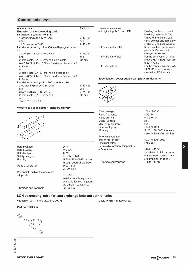
Accessories Part no.Extension of the connecting cable Installation spacing 7 to 14 m – 1 connecting cable (7 m long)
and1 LON coupling RJ45
7143 495and7143 496
Installation spacing 14 to 900 m with plug-in connec-tor
– 2 LON plug-in connectors RJ45and
7199 251and
– 2-core cable, CAT5, screened, solid cable,AWG 26-22, 0.13 to 0.32 mm2, external diameter, 4.5to 8 mmor2-core cable, CAT5, screened, flexible cable,AWG 26-22, 0.14 to 0.36 mm2, external diameter, 4.5to 8 mm.
On site
Installation spacing 14 to 900 m with socket – 2 connecting cables (7 m long)
and– 2 LON sockets RJ45, CAT6
7143 495and7171 784
– 2-core cable, CAT5, screenedorJY(St) Y 2 x 2 x 0.8
On site
Vitocom 300 specification (standard delivery):
15190
73
Rated voltage 24 V–Rated current 710 mARated output 17 WSafety category II to EN 61140IP rating IP 30 to EN 60529; ensure
through design/installationMode of operation Type 1B to
EN 60730-1Permissible ambient temperature – Operation 0 to +50 °C
Installation in living spacesor installation rooms (stand-ard ambient conditions)
– Storage and transport −20 to +85 °C
On-site connections: – 2 digital inputs DI1 and DI2 Floating contacts, contact
breaking capacity 24 V–,7 mA, for monitoring addi-tional devices and third partysystems, with LED indicator
– 1 digital output DO Relay, contact breaking ca-pacity 24 V–, max. 2 A,changeover contact
– 1 M BUS interface For the connection of heatmeters with M BUS interfaceto EN 1434-3
– 1 EM interface For the connection of up to 3x EM301 extension mod-ules, with LED indicator
Specification, power supply unit (standard delivery):
7290
58Rated voltage 100 to 240 V~Rated frequency 50/60 HzRated current 0.8 to 0.4 AOutput voltage 24 V–Max. output current 2 ASafety category II to EN 61140IP rating IP 20 to EN 60529; ensure
through design/installationPotential separationprimary/secondary SELV to EN 60950Electrical safety EN 60335Permissible ambient temperature – Operation −20 to +55 °C
Installation in living spacesor installation rooms (stand-ard ambient conditions)
– Storage and transport −25 to +85 °C
LON connecting cable for data exchange between control unitsVitotronic 300-K for the Vitotronic 200-H
Part no. 7143 495
Cable length 7 m, fully wired.
Control units (cont.)
VITODENS 200-W VIESMANN 75
5822
432
GB
5
Extension of the connecting cable■ Installation spacing 7 to 14 m:
– 2 connecting cables (7.0 m long)Part no. 7143 495
– 1 LON coupling RJ45Part no. 7143 496
■ Installation spacing 14 to 900 m with plug-in connectors:– 2 LON plug-in connectors
Part no. 7199 251– 2-core cable:
CAT5, screenedorSolid conductor AWG 26-22/0.13 mm2 to 0.32 mm2,conductor AWG 26-22/0.14 mm2 to 0.36 mm2
7 4.5 mm - 8 mm
on site■ Installation spacing 14 to 900 m with junction boxes:
– 2 connecting cables (7.0 m long)Part no. 7143 495
– 2-core cable:CAT5, screenedorSolid conductor AWG 26-22/0.13 mm2 to 0.32 mm2,conductor AWG 26-22/0.14 mm2 to 0.36 mm2
7 4.5 mm to 8 mmon site
– 2 LON sockets RJ45, CAT6Part no. 7171 784
Terminator (2 pce)
Part no. 7143 497For terminating the LON BUS at the first and last control unit.
LON communication module
PCB for exchanging data with the Vitotronic 200-H, Vitocom 100 typeLAN1, Vitocom 200 and for connecting to a higher ranking buildingmanagement system.
■ For installation in the Vitotronic 200Part no. 7179 113
■ For installation in the Vitotronic 300-KPart no. 7172 174
Appendix
6.1 Regulations / Directives
Regulations and DirectivesThe design and operational characteristics of the Vitodens gas con-densing boilers from Viessmann meet the requirements of EN 297.They are CE-designated.They may be installed in sealed unvented heating systems with per-missible flow temperatures (= safety temperatures) up to 100 °C toEN 12828. The maximum achievable flow temperature is approx.15 K below the safety temperature.Observe all engineering standards and statutory requirements appli-cable to the installation and operation of this system in your country.Only qualified contractors should carry out the installation, the mainsgas connection and the connection on the flue gas side, the commis-sioning and the electrical connection as well as general maintenanceand repair work.The installation of a condensing boiler may need to be notified to andapproved by your local gas supply utility.
In some regions, permits may be required for the flue system and con-densate drain into the public sewage system.In some countries, the relevant flue gas inspector and water authoritiesmust be informed prior to commencing the installation.We recommend that maintenance and cleaning procedures are per-formed annually. As part of the maintenance procedure, check thecorrect function of the entire system. Remedy any faults.Condensing boilers must only be operated with specially designed,tested and approved flue pipes.Only an authorised contractor may convert this boiler for use in coun-tries other than those stated on the type plate. That contractor mustalso arrange the acceptance in accordance with the statutes of therelevant country.
EnEV Energy Saving Ordinance1st BImSchV First regulation for the implementation of the German Immissions Act (regulation regarding small and me-
dium-sized combustion equipment)FeuVo Fire Regulations of the German Federal StatesDIN 1986 Drainage system materialsDIN 1988 DHW pipe systems for propertiesDIN 4753 Water heaters and DHW systems for DHW and process waterDIN 18160 Domestic chimneysDIN 18380 Heating systems and central DHW heating systems (VOB)DIN 57116 Electrical equipment for combustion systemsEN 677 Gas condensing boilerEN 12828 Heating systems in buildings - design of hot water heating systemsEN 12831 Heating systems in buildings - process for calculating the standard heat loadEN 13384 Flue systems - thermal and flow technical calculationsDWA-A 251 Introduction of condensate from gas and oil combustion systems [into public sewers]DVGW G 260 Gas conditionDVGW G 600 Technical rules for gas installations (TRGI)DVGW G 688 Gas consumption equipment, condensing technology
Control units (cont.)
76 VIESMANN VITODENS 200-W
658
22 4
32 G
B
DVGW/DVFG Technical rules for LPG (TRF)DVGW VP 113 Systems comprising combustion equipment and fluesVDI 2035 Prevention of damage in water heating installations - scale formation in DHW supply installations and water
heating installationsVdTÜV 1466 Water quality datasheetVDE regulations and the special regulations of local power supply utilities.
Appendix (cont.)
VITODENS 200-W VIESMANN 77
5822
432
GB
6
AAccessories– For control units............................................................................55AM1 extension.................................................................................69Anti-corrosion agents.......................................................................46Antifreeze.........................................................................................46
BBoiler water temperature sensor................................................49, 51
CCarbon monoxide.................................................................19, 28, 29Cascade control unit........................................................................52CO limiter.............................................................................19, 28, 29Combustion air supply......................................................................28Condensate......................................................................................44Condensate connection...................................................................43Constant temperature control unit– Frost protection function...............................................................49– Functions......................................................................................49– Heating programs.........................................................................49– Layout...........................................................................................49– Programming unit..........................................................................49– Standard unit.................................................................................49Contact temperature controller.........................................................67Control unit– For constant temperature operation..............................................49– For weather-compensated operation............................................50
DDistributor with low loss header.......................................................48
EEA1 extension..................................................................................70Electrical connection........................................................................29EnEV..........................................................................................51, 53Expansion vessel.............................................................................47Extension– Internal H1....................................................................................69– Internal H2....................................................................................69Extension kit for mixer– Separate mixer motor...................................................................65
FFill water...........................................................................................46Frost protection function.......................................................49, 51, 54
GGas connection................................................................................30
HHeating curve adjustment................................................................51Hydraulic connection........................................................................46
IImmersion temperature controller....................................................67Initial heat-up....................................................................................46Installation room...............................................................................28Interlock circuit.................................................................................28Interlock switch.................................................................................30Internal extension H1.......................................................................69Internal extension H2.......................................................................69
KKM BUS distributor...........................................................................64
LLeads/cables....................................................................................30Level.................................................................................................51LON communication module............................................................76Low loss header...............................................................................47Low loss headers.............................................................................47Low water indicator..........................................................................46
MMixer extension– Integral mixer motor................................................................65, 66– Separate mixer motor...................................................................65Mixer extension kit– Integral mixer motor................................................................65, 66Mounting base for programming unit...............................................64
NNeutralisation...................................................................................44Neutralising system..........................................................................44
OOpen flue operation..........................................................................28Outside temperature sensor.......................................................51, 54
PProtection.........................................................................................29
RRoom sealed operation....................................................................29Room temperature controller.....................................................56, 57Room temperature sensor...............................................................63Room thermostat........................................................................56, 57
SSafety equipment.............................................................................46Safety valve......................................................................................46Siting conditions...............................................................................28Slope................................................................................................51Solar control module– Specification..................................................................................68Specification– Solar control module.....................................................................68Standard unit....................................................................................50System design..................................................................................46
TTemperature controller– Contact temperature.....................................................................67– Immersion temperature.................................................................67Temperature sensor– Room temperature sensor............................................................63– Wireless outside temperature sensor...........................................62Temperature sensors– Boiler water temperature sensor.............................................49, 51– Outside temperature sensor...................................................51, 54Thermally activated safety shut-off valve.........................................31Time switch................................................................................51, 53
Keyword index
78 VIESMANN VITODENS 200-W
5822
432
GB
VVitocom– 100, type GSM..............................................................................71– 100, type LAN1.............................................................................70Vitotrol– 200A..............................................................................................58– 200 RF..........................................................................................60– 300A..............................................................................................59– 300 RF with table-top dock...........................................................60– 300 RF with wall mounting bracket...............................................61Vitotrol 100– UTA...............................................................................................56– UTDB............................................................................................56– UTDB-RF......................................................................................57
WWater quality....................................................................................46Weather-compensated control– Operating programs......................................................................51Weather-compensated control unit– Frost protection function.........................................................51, 54– Functions......................................................................................50– Layout...........................................................................................50– Programming unit..........................................................................50– Standard unit.................................................................................50Wet area...........................................................................................29Wireless components– Wireless base station....................................................................62– Wireless outside temperature sensor...........................................62– Wireless remote control..........................................................60, 61– Wireless repeater..........................................................................63
Keyword index
VITODENS 200-W VIESMANN 79
5822
432
GB

80 VIESMANN VITODENS 200-W
5822
432
GB
Subject to technical modifications.
Viessmann LimitedHortonwood 30, TelfordShropshire, TF1 7YP, GBTelephone: +44 1952 675000Fax: +44 1952 675040E-mail: [email protected]
Viessmann Werke GmbH&Co KGD-35107 AllendorfTelephone: +49 6452 70-0Fax: +49 6452 70-2780www.viessmann.com