Vitoden 200-W installation - Heating systems | Industrial ... · VITODENS 200-W Installation...
76
VITODENS 200-W Installation Instructions For Corgi Registered Heating Engineers Vitodens 200-W Type WB2B, 4.8 to 35.0 kW Wall mounted gas fired condensing boiler Natural Gas and LPG version 5350 485 GB 06/2007 Please keep these instructions in a safe place
Transcript of Vitoden 200-W installation - Heating systems | Industrial ... · VITODENS 200-W Installation...
VITODENS 200-W
Installation InstructionsFor Corgi Registered Heating Engineers
Vitodens 200-W
Type WB2B, 4.8 to 35.0 kWWall mounted gas fired condensing boilerNatural Gas and LPG version
5350 485 GB 06/2007 Please keep these instructions in a safe place
Index
Product information . . . . . . . . . . . . . . . . . . . . . . . . . . . . . . . . . . . . . . . . . . . . . . . . . . . . . 4
Safety instructions . . . . . . . . . . . . . . . . . . . . . . . . . . . . . . . . . . . . . . . . . . . . . . . . . . . . . . . 5
Technical specification . . . . . . . . . . . . . . . . . . . . . . . . . . . . . . . . . . . . . . . . . . . . . . . . . . . 7
Appliance dimensions/connections . . . . . . . . . . . . . . . . . . . . . . . . . . . . . . . . . . . . . . . 9
Installation clearances . . . . . . . . . . . . . . . . . . . . . . . . . . . . . . . . . . . . . . . . . . . . . . . . . . 10
Sectional Diagram . . . . . . . . . . . . . . . . . . . . . . . . . . . . . . . . . . . . . . . . . . . . . . . . . . . . . . 11
Installation requirements . . . . . . . . . . . . . . . . . . . . . . . . . . . . . . . . . . . . . . . . . . . . . . . . 12
Statutory requirements . . . . . . . . . . . . . . . . . . . . . . . . . . . . . . . . . . . . . . . . . . . . . . . . . . . . . 12
Boiler position . . . . . . . . . . . . . . . . . . . . . . . . . . . . . . . . . . . . . . . . . . . . . . . . . . . . . . . . . . . . 12
Flue terminal position . . . . . . . . . . . . . . . . . . . . . . . . . . . . . . . . . . . . . . . . . . . . . . . . . . . . . . 13
Flue system . . . . . . . . . . . . . . . . . . . . . . . . . . . . . . . . . . . . . . . . . . . . . . . . . . . . . . . . . . . . . . 16
Plume kit installation instructions . . . . . . . . . . . . . . . . . . . . . . . . . . . . . . . . . . . . . . . . . . . . . 19
Ventilation requirements . . . . . . . . . . . . . . . . . . . . . . . . . . . . . . . . . . . . . . . . . . . . . . . . . . . . 22
Hydraulic connections (typical system designs) . . . . . . . . . . . . . . . . . . . . . . . . . . . . . . . . . . 23
Gas and electric supply . . . . . . . . . . . . . . . . . . . . . . . . . . . . . . . . . . . . . . . . . . . . . . . . . . . . . 27
Electricity supply . . . . . . . . . . . . . . . . . . . . . . . . . . . . . . . . . . . . . . . . . . . . . . . . . . . . . . . . . . 27
Electrical connections . . . . . . . . . . . . . . . . . . . . . . . . . . . . . . . . . . . . . . . . . . . . . . . . . . . . . . 28
Control unit . . . . . . . . . . . . . . . . . . . . . . . . . . . . . . . . . . . . . . . . . . . . . . . . . . . . . . . . . . . . . . 29
Hydraulic components . . . . . . . . . . . . . . . . . . . . . . . . . . . . . . . . . . . . . . . . . . . . . . . . . . . . . . 32
Integral expansion vessel . . . . . . . . . . . . . . . . . . . . . . . . . . . . . . . . . . . . . . . . . . . . . . . . . . . 32
Installation of boilerUnpacking the appliance (lifting advice) . . . . . . . . . . . . . . . . . . . . . . . . . . . . . . . . . . . . . . . . . 33
Preparing the connections . . . . . . . . . . . . . . . . . . . . . . . . . . . . . . . . . . . . . . . . . . . . . . . . . . . 34
Wall mounting bracket installation . . . . . . . . . . . . . . . . . . . . . . . . . . . . . . . . . . . . . . . . . . . . . 35
Installing the boiler and making connections (lifting advice) . . . . . . . . . . . . . . . . . . . . . . . . . 38
Safety discharge connection. . . . . . . . . . . . . . . . . . . . . . . . . . . . . . . . . . . . . . . . . . . . . . . . . . 39
Condensate connection . . . . . . . . . . . . . . . . . . . . . . . . . . . . . . . . . . . . . . . . . . . . . . . . . . . . . 40
Gas connection . . . . . . . . . . . . . . . . . . . . . . . . . . . . . . . . . . . . . . . . . . . . . . . . . . . . . . . . . . . 43
Flue outlet . . . . . . . . . . . . . . . . . . . . . . . . . . . . . . . . . . . . . . . . . . . . . . . . . . . . . . . . . . . . . . . 44
2 5350
485
GB
06/
2007
Index
Electrical connections . . . . . . . . . . . . . . . . . . . . . . . . . . . . . . . . . . . . . . . . . . . . . . . . . . . 46
Combination boiler . . . . . . . . . . . . . . . . . . . . . . . . . . . . . . . . . . . . . . . . . . . . . . . . . . . . . . . . . 47
System boiler - Separate heating and DHW circuits (4 pipes) . . . . . . . . . . . . . . . . . . . . . . . 48
System boiler - Calling up code 2 . . . . . . . . . . . . . . . . . . . . . . . . . . . . . . . . . . . . . . . . . . . . . 49
System boiler - Y & S plan systems (2 pipes) . . . . . . . . . . . . . . . . . . . . . . . . . . . . . . . . . . . . 50
System boiler - Heating only (2 pipes) . . . . . . . . . . . . . . . . . . . . . . . . . . . . . . . . . . . . . . . . . . 50
Routing cables and connecting cylinder sensor . . . . . . . . . . . . . . . . . . . . . . . . . . . . . . . . . . . 51
Filling the heating system . . . . . . . . . . . . . . . . . . . . . . . . . . . . . . . . . . . . . . . . . . . . . . . 53
Venting the boiler . . . . . . . . . . . . . . . . . . . . . . . . . . . . . . . . . . . . . . . . . . . . . . . . . . . . . . . 54
Venting the heating system . . . . . . . . . . . . . . . . . . . . . . . . . . . . . . . . . . . . . . . . . . . . . 54
Checking diaphragm, expansion vessel and system pressure . . . . . . . . . . . . . . 56
Checking the gas type . . . . . . . . . . . . . . . . . . . . . . . . . . . . . . . . . . . . . . . . . . . . . . . . . . . 56
Gas type conversion (LPG) . . . . . . . . . . . . . . . . . . . . . . . . . . . . . . . . . . . . . . . . . . . . . . 57
Checking the static and supply pressure . . . . . . . . . . . . . . . . . . . . . . . . . . . . . . . . . . 58
Setting maximum output . . . . . . . . . . . . . . . . . . . . . . . . . . . . . . . . . . . . . . . . . . . . . . . 60
Checking the balanced flue system for soundness . . . . . . . . . . . . . . . . . . . . . . . . 61
Check the gas installation for soundness . . . . . . . . . . . . . . . . . . . . . . . . . . . . . . . . . 61
Flue gas emissions test . . . . . . . . . . . . . . . . . . . . . . . . . . . . . . . . . . . . . . . . . . . . . . . . . 61
Heating system start up . . . . . . . . . . . . . . . . . . . . . . . . . . . . . . . . . . . . . . . . . . . . . . . . . 63
Function sequence and possible faults . . . . . . . . . . . . . . . . . . . . . . . . . . . . . . . . . . . 68
Fitting the outer case . . . . . . . . . . . . . . . . . . . . . . . . . . . . . . . . . . . . . . . . . . . . . . . . . . . 70
Benchmark . . . . . . . . . . . . . . . . . . . . . . . . . . . . . . . . . . . . . . . . . . . . . . . . . . . . . . . . . . . . . 71
Declaration of conformity . . . . . . . . . . . . . . . . . . . . . . . . . . . . . . . . . . . . . . . . . . . . . . . 73
Applicability . . . . . . . . . . . . . . . . . . . . . . . . . . . . . . . . . . . . . . . . . . . . . . . . . . . . . . . . . . . . 75
For maintenance and spares information see Service instructions 5692 672
35350
485
GB
06/
2007
4
Product information
Vitodens 200-W
Type WB2B, 4.8 to 35.0 kW
Set up for operation with natural gas.
Boiler Type GC number
Vitodens 200-W WB2B System, 19kW 41-819-14Vitodens 200-W WB2B System, 26kW 41-819-15Vitodens 200-W WB2B Combi, 26kW 47-819-09Vitodens 200-W WB2B System, 30kW 47-819-16Vitodens 200-W WB2B Combi, 30kW 47-819-10Vitodens 200-W WB2B System, 35kW 47-819-17Vitodens 200-W WB2B Combi, 35kW 47-819-11
Appliance description
The Vitodens 200-W is a fully automatic,wall hung, fan assisted balanced flue condensing boiler for use with natural gas(G20) and LPG. For gas type conversions see page 63.
The Vitodens 200-W is fully modulatingand provides central heating outputsbetween 4.8kW and 35.0kW and instantaneous hot water outputs between 4.8kW and 35.0kW.
The appliance always gives priority todomestic water supply.
Certification details
The Vitodens 200-W is certified to complywith the requirements of EN 483 and EN 625 for use in GB and IE (Great Britain and Ireland) using gas category 2H (G20 with a governed gas supply at 20 mbar (8 in. wg) inlet pressure).
The appliance is designed for use withsealed primary water systems (only) andincorporates a circulation pump, divertervalve assembly, flow switch (combinationboiler only), DHW plate-type heatexchanger (combination boiler only), safety valve and CH expansion vessel. A separate DHW expansion vessel is notrequired. Internal frost protection and an electronic control unit is fitted as standard equipment and the boiler may be used with any suitable room thermostat, cylinder thermostat and / or time clock in addition to theoptional controls available fromViessmann.
Asbestos, mercury or CFCs have not and will not be used in this product.
The appliance classification is either C13 or C33 depending upon whether a horizontal or vertical flue terminal isused.
5350
485
GB
06/
2007
5
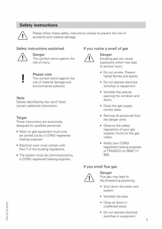
Safety instructions
Please follow these safety instructions closely to prevent the risk of accidents and material damage.
Safety instructions explained
DangerThis symbol warns against therisk of injury.
Please noteThis symbol warns against therisk of material damage andenvironmental pollution.
NoteDetails identified by the word ‘Note’ contain additional information.
TargetThese instructions are exclusivelydesigned for qualified personnel.
• Work on gas equipment must only be carried out by a CORGI registeredheating engineer.
• Electrical work must comply with Part P of the building regulations.
• The system must be commissioned bya CORGI registered heating engineer.
If you notice a smell of gas
DangerEscaping gas can cause explosions which may lead to serious injury.
• Do not smoke. Preventnaked flames and sparks.
• Do not operate electricalswitches or equipment.
• Ventilate the area by opening the windows anddoors.
• Close the gas supply control valve.
• Remove all personnel fromthe danger zone.
• Observe the safety regulations of your gas supplier, found on the gasmeter.
• Notify your CORGI registered heating engineeror TRANSCO on 0800 111999.
If you smell flue gas
DangerFlue gas may lead to life-threatening poisoning.
• Shut down the boiler andsystem
• Ventilate the area.
• Close all doors in unaffected areas.
• Do not operate electricalswitches or equipment.
5350
485
GB
06/
2007
6
Safety instructions (cont.)
Working on the system
• Close the main gas shut-off valve and safeguard against unauthorised reconnection.
• Isolate the system from the electricitypower supply, check that it is no longer‘live’ and safeguard the electricity supply against unauthorised reconnection.
Please noteElectronic modules can bedamaged by electro-static-discharges. Touch earthedobjects, such as heating orwater pipes, to discharge static loads ensuring anyappropriate electrical safetysteps have been taken inadvance.
Repair work
Please noteRepairing components whichfulfil a safety function cancompromise the safe operation of your heating system. Replace faulty components only with originalViessmann spare parts.
Ancillary components
Please noteParts which have not beentested together with the heating system can compromise its function.Installing non-authorised components and non-approved modifications/conversions can compromisesafety and may invalidate theappliance warranty. Forreplacements, use only original spare parts fromViessmann or those which are approved by Viessmann.
5350
485
GB
06/
2007
7
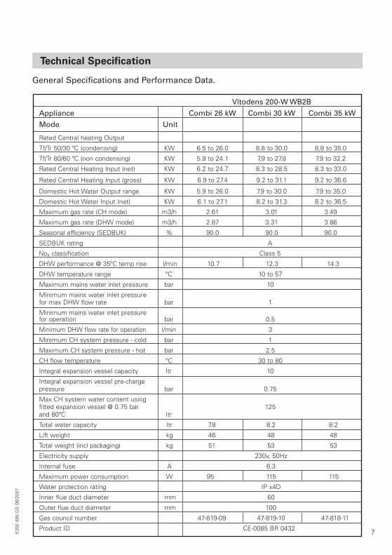
Technical Specification
General Specifications and Performance Data.
5350
485
GB
06/
2007
Vitodens 200-W WB2B
Appliance Combi 26 kW Combi 30 kW Combi 35 kW
Mode Unit
Rated Central heating Output
Tf/Tr 50/30 ºC (condensing) KW 6.5 to 26.0 8.8 to 30.0 8.8 to 35.0
Tf/Tr 80/60 ºC (non condensing) KW 5.9 to 24.1 7.9 to 27.8 7.9 to 32.2
Rated Central Heating Input (net) KW 6.2 to 24.7 8.3 to 28.5 8.3 to 33.0
Rated Central Heating Input (gross) KW 6.9 to 27.4 9.2 to 31.1 9.2 to 36.6
Domestic Hot Water Output range KW 5.9 to 26.0 7.9 to 30.0 7.9 to 35.0
Domestic Hot Water Input (net) KW 6.1 to 27.1 8.2 to 31.3 8.2 to 36.5
Maximum gas rate (CH mode) m3/h 2.61 3.01 3.49
Maximum gas rate (DHW mode) m3/h 2.87 3.31 3.86
Seasonal efficiency (SEDBUK) % 90.0 90.0 90.0
SEDBUK rating A
Nox classification Class 5
DHW performance @ 35ºC temp rise l/min 10.7 12.3 14.3
DHW temperature range ºC 10 to 57
Maximum mains water inlet pressure bar 10
Minimum mains water inlet pressurefor max DHW flow rate bar 1
Minimum mains water inlet pressurefor operation bar 0.5
Minimum DHW flow rate for operation l/min 3
Minimum CH system pressure - cold bar 1
Maximum CH system pressure - hot bar 2.5
CH flow temperature ºC 30 to 80
Integral expansion vessel capacity ltr 10
Integral expansion vessel pre-charge pressure bar 0.75
Max CH system water content usingfitted expansion vessel @ 0.75 bar 125and 80ºC ltr
Total water capacity ltr 7.8 8.2 8.2
Lift weight kg 46 48 48
Total weight (incl packaging) kg 51 53 53
Electricity supply 230v, 50Hz
Internal fuse A 6.3
Maximum power consumption W 95 115 115
Water protection rating IP x4D
Inner flue duct diameter mm 60
Outer flue duct diameter mm 100
Gas council number 47-819-09 47-819-10 47-818-11
Product ID CE-0085 BR 0432
8 5350
485
GB
06/
2007
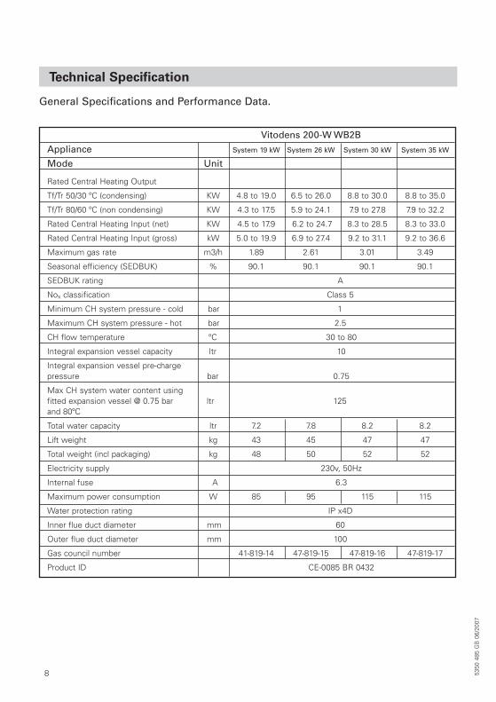
Technical Specification
General Specifications and Performance Data.
Vitodens 200-W WB2B
Appliance System 19 kW System 26 kW System 30 kW System 35 kW
Mode Unit
Rated Central Heating Output
Tf/Tr 50/30 ºC (condensing) KW 4.8 to 19.0 6.5 to 26.0 8.8 to 30.0 8.8 to 35.0
Tf/Tr 80/60 ºC (non condensing) KW 4.3 to 17.5 5.9 to 24.1 7.9 to 27.8 7.9 to 32.2
Rated Central Heating Input (net) KW 4.5 to 17.9 6.2 to 24.7 8.3 to 28.5 8.3 to 33.0
Rated Central Heating Input (gross) kW 5.0 to 19.9 6.9 to 27.4 9.2 to 31.1 9.2 to 36.6
Maximum gas rate m3/h 1.89 2.61 3.01 3.49
Seasonal efficiency (SEDBUK) % 90.1 90.1 90.1 90.1
SEDBUK rating A
Nox classification Class 5
Minimum CH system pressure - cold bar 1
Maximum CH system pressure - hot bar 2.5
CH flow temperature ºC 30 to 80
Integral expansion vessel capacity ltr 10
Integral expansion vessel pre-charge pressure bar 0.75
Max CH system water content usingfitted expansion vessel @ 0.75 bar ltr 125and 80ºC
Total water capacity ltr 7.2 7.8 8.2 8.2
Lift weight kg 43 45 47 47
Total weight (incl packaging) kg 48 50 52 52
Electricity supply 230v, 50Hz
Internal fuse A 6.3
Maximum power consumption W 85 95 115 115
Water protection rating IP x4D
Inner flue duct diameter mm 60
Outer flue duct diameter mm 100
Gas council number 41-819-14 47-819-15 47-819-16 47-819-17
Product ID CE-0085 BR 0432
9
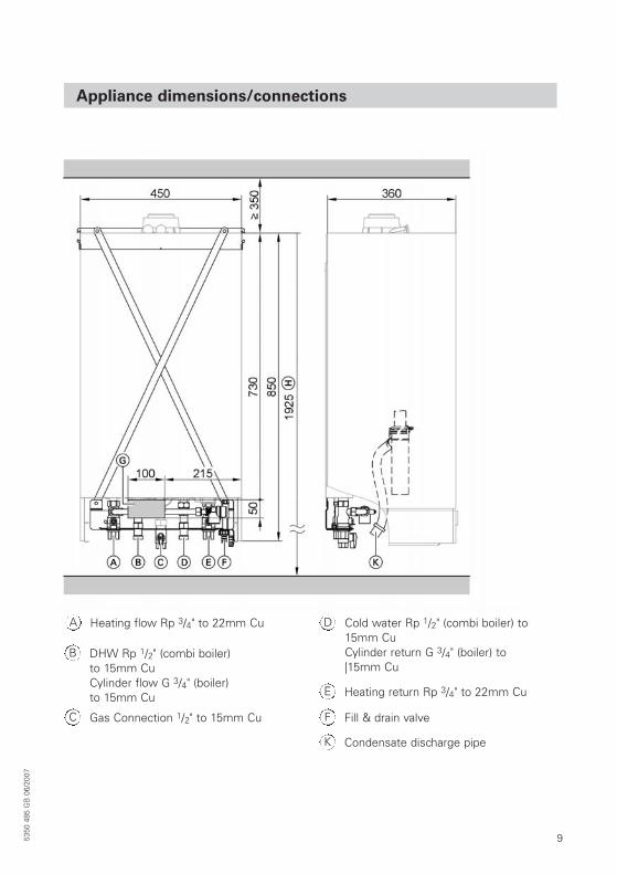
Appliance dimensions/connections
5350
485
GB
06/
2007
Heating flow Rp 3/4" to 22mm CuA
DHW Rp 1/2" (combi boiler) to 15mm CuCylinder flow G 3/4" (boiler) to 15mm Cu
B
Gas Connection 1/2" to 15mm CuC
Cold water Rp 1/2" (combi boiler) to15mm CuCylinder return G 3/4" (boiler) to|15mm Cu
D
Heating return Rp 3/4" to 22mm CuE
Fill & drain valveF
Condensate discharge pipeK
10 5350
485
GB
06/
2007
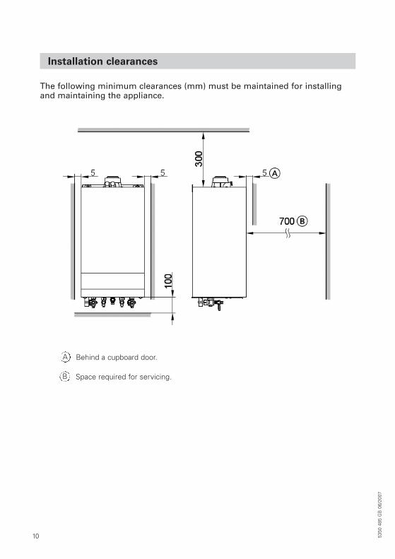
Installation clearances
The following minimum clearances (mm) must be maintained for installingand maintaining the appliance.
Behind a cupboard door.A
Space required for servicing.B
11
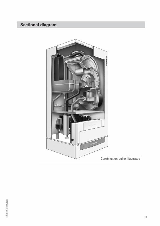
Sectional diagram
Combination boiler illustrated
5350
485
GB
06/
2007
12 5350
485
GB
06/
2007
In addition to the above regulations, thisappliance must be installed in accordancewith the current IEE Wiring Regulationsfor electrical installation (BS 7671), localBuilding Regulations, the BuildingStandards (Scotland) (Consolidation)Regulations, bye laws of the local waterundertaking and Health and SafetyDocument No. 635 ‘The Electricity atWork regulations 1989’.
In Ireland (IE), the installation must be carried out by a Competent Person andinstalled in accordance with the currentedition if I.S.813 “Domestic GAsInstalltions”, the current BuildingRegulations and reference should bemade to the current ETCI rules for electrical installation.
It should also be in accordance with therelevant recommendations in the currenteditions of the following British Standardsand Codes of Practice: BS 5449, BS 5546,BS 5440:1, BS 5440:2, BS 6798, BS 7593,BS 6891, IGE/UP/7 and IS 813 for IE
All CORGI Registered installers arerequired to notify building control whenthey have installed or exchanged a gasappliance in a residential dwelling, thiscan be done via CORGI.
CORGI will then issue either a BuildingCompliance Certificate (for England andWales) or a Declaration of Safety(Scotland, Northern Ireland, Isle of Man or appliances out of the scope of BuildingRegulations) to the homeowner, whichwill confirm that the work has been carried out by a competent CORGIRegistered Installer. This document will be used to form part of the HomeInformation Pack (HIP).
Please noteManufacturers instructionsmust not be taken in any way as overriding statutoryobligations.
Boiler position
The following limitations must beobserved when siting the boiler:
• The boiler is not suitable for externalinstallation. The position selected forinstallation should be within the building, unless otherwise protected by a suitable enclosure and must allowadequate space for installation, servicing and operation of the applianceand for air circulation around it.
• The position must allow for a suitableflue system and terminal position. The boiler must be installed on a flatvertical wall capable of supporting the weight of the appliance and anyancillary equipment when full.
• Due consideration should be given tothe routing of the condensate drainfrom the chosen position.
• If the boiler is to be fitted in a timberframed building it should be fitted inaccordance with IGE/UP/7. If in doubtadvice must be sought from the Institute of Gas Engineers.
Installation requirements
Statutory requirementsThe appliance is suitable only for installation in GB and IE and should be installed in accordance with the rules in force. In GB, a corgi Registered Installer must carry out theinstallation. It must be carried out in accordance with the relevant requirements of the:
Gas safety (installation and use) regulations (current issue)It is in your own interest and safety to ensure that the law is complied with.
13
Flue terminal position
• If the appliance is to be installed in aroom containing a bath or shower, anyelectrical switch or control utilising mains electricity must be sosituated that it cannot be touched by aperson using the bath or shower.Attention is drawn to the requirements of BS 7671 (the current I.E.E Wiring Regulations) and inScotland the electrical provisions ofthe Building Regulations applicable in Scotland.
• A compartment used to enclose theappliance must be designed andconstructed specifically for this purpose. An existing cupboard orcompartment may be used provided itis modified accordingly. BS 7698:2000gives details of the essential featuresof cupboard / compartment design,including airing cupboards.
• Where installation will be in an unusuallocation, special procedures may benecessary. BS 6798 gives detailedguidance on this aspect.
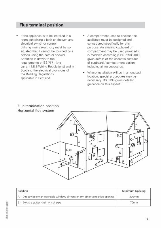
Flue termination positionHorizontal flue system
Position
A
B
300mm
75mm
Directly below an openable window, air vent or any other ventilation opening
Below a gutter, drain or soil pipe
Minimum Spacing
5350
485
GB
06/
2007
14 5350
485
GB
06/
2007
Flue terminal position (cont.)
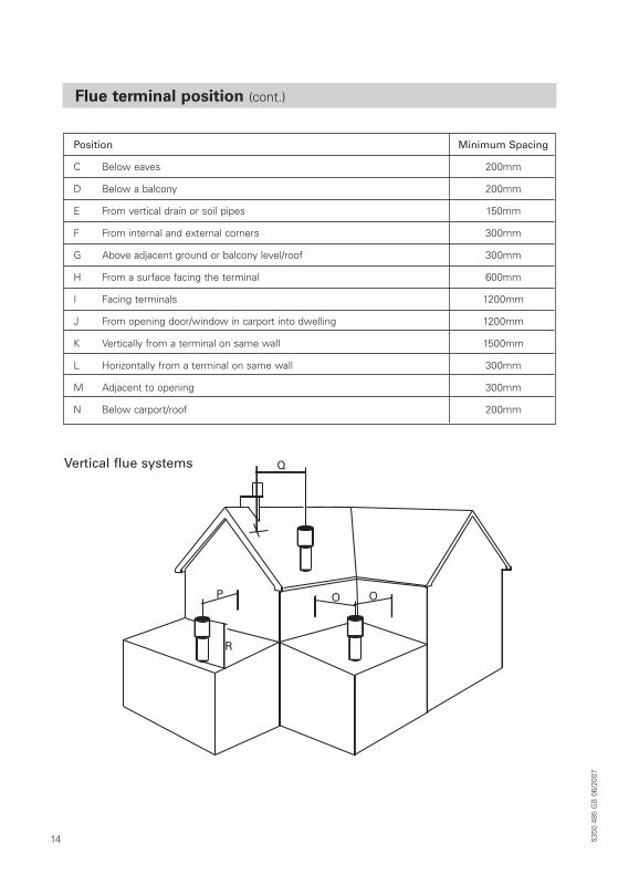
Vertical flue systems
Position
C
D
E
F
G
H
I
J
K
L
M
N
200mm
200mm
150mm
300mm
300mm
600mm
1200mm
1200mm
1500mm
300mm
300mm
200mm
Below eaves
Below a balcony
From vertical drain or soil pipes
From internal and external corners
Above adjacent ground or balcony level/roof
From a surface facing the terminal
Facing terminals
From opening door/window in carport into dwelling
Vertically from a terminal on same wall
Horizontally from a terminal on same wall
Adjacent to opening
Below carport/roof
Minimum Spacing
15
Flue terminal position (cont.)
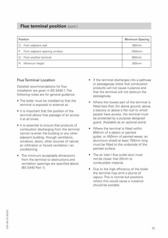
Position
O
P
Q
R
300mm
1000mm
600mm
300mm
From adjacent wall
From adjacent opening window
From another terminal
Minimum height
Minimum Spacing
Flue Terminal Location
Detailed recommendations for flue installation are given in BS 5440:1. The following notes are for general guidance.
• The boiler must be installed so that theterminal is exposed to external air.
• It is important that the position of the terminal allows free passage of air acrossit at all times.
• It is essential to ensure that products ofcombustion discharging from the terminalcannot re-enter the building or any otheradjacent building, through ventilators,windows, doors, other sources of naturalair infiltration or forced ventilation / airconditioning.
• The minimum acceptable dimensionsfrom the terminal to obstructions andventilation openings are specified above(BS 5440 Part 1).
• If the terminal discharges into a pathwayor passageway check that combustionproducts will not cause nuisance andthat the terminal will not obstruct thepassageway.
• Where the lowest part of the terminal isfitted less than 2m above ground, abovea balcony or above a flat roof to whichpeople have access, the terminal mustbe protected by a purpose designedguard. (Available as an optional extra).
• Where the terminal is fitted within850mm of a plastic or painted gutter, or 450mm of painted eaves, analuminium shield at least 750mm longmust be fitted to the underside of thepainted surface.
• The air inlet / flue outlet duct must not be closer that 25mm to combustible material.
• Due to the high efficiency of the boilerthe terminal may emit a plume ofvapour. This is normal but positionswhere this would cause a nuisanceshould be avoided.
5350
485
GB
06/
2007
16 5350
485
GB
06/
2007
Flue system
Flue gas temperature protection
The flue pipes are approved for flue gas temperatures up to 120 ºC. The interiordesign of Viessmann condensing boilersensures that the maximum permissible fluegas temperature will not be exceeded.
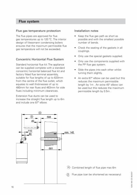
Concentric Horizontal Flue System
Standard horizontal flue kit: The appliancecan be supplied complete with a standardconcentric horizontal balanced flue kit andfactory fitted flue terminal assembly, suitable for flue lengths of up to 620mmfrom the centre of the flue outlet, whichequates to wall thicknesses of up to480mm for rear flues and 463mm for sideflues including minimum clearances.
Extension flue ducts can be used toincrease the straight flue length up to 6mand include one 87º elbow.
Installation notes
• Keep the flue gas path as short as possible and with the smallest possiblenumber of bends.
• Check the seating of the gaskets in allcouplings.
• Only use the special gaskets supplied.
• Only use the components supplied withthe PP flue gas system.
• Slide the pipes into each other whilstturning them slightly.
• An extra 87° elbow can be used but thisreduces the maximum permissiblelength by 1m . An extra 45° elbow canbe used but this reduces the maximumpermissible length by 0.5m .
Combined length of flue pipe max 6mA
Flue pipe (can be shortened as necessary)B
17
Flue system (cont.)
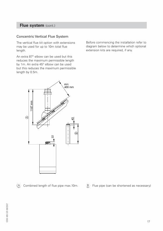
Concentric Vertical Flue System
The vertical flue kit option with extensionsmay be used for up to 10m total fluelength.
An extra 87° elbow can be used but thisreduces the maximum permissible lengthby 1m. An extra 45° elbow can be used but this reduces the maximum permissiblelength by 0.5m.
Before commencing the installation refer todiagram below to determine which optionalextension kits are required, if any.
Combined length of flue pipe max.10m.A Flue pipe (can be shortened as necessary)B
5350
485
GB
06/
2007
18 5350
485
GB
06/
2007
Flue system (cont.)
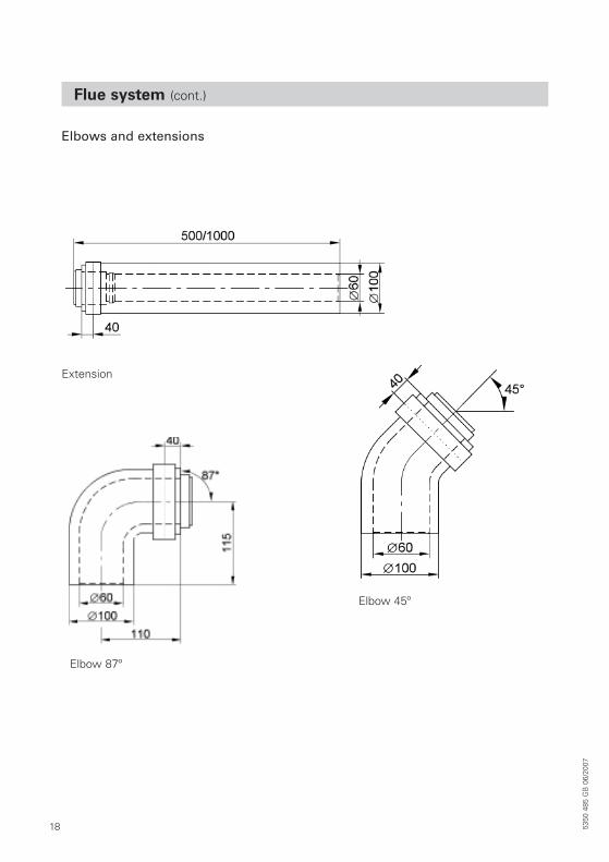
Elbows and extensions
Extension
Elbow 87º
Elbow 45º
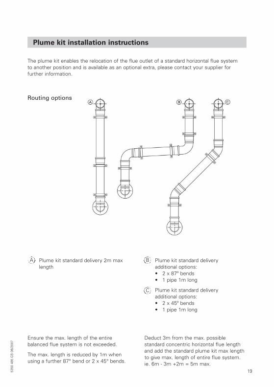
Plume kit standard delivery 2m maxlength
A Plume kit standard deliveryadditional options:• 2 x 87º bends• 1 pipe 1m long
Plume kit standard deliveryadditional options:• 2 x 45º bends• 1 pipe 1m long
B
C
Ensure the max. length of the entire balanced flue system is not exceeded.
The max. length is reduced by 1m whenusing a further 87° bend or 2 x 45° bends.
Deduct 3m from the max. possible standard concentric horizontal flue lengthand add the standard plume kit max lengthto give max. length of entire flue system.ie. 6m - 3m +2m = 5m max.
19
Plume kit installation instructions
Routing options
The plume kit enables the relocation of the flue outlet of a standard horizontal flue system to another position and is available as an optional extra, please contact your supplier for further information.
5350
485
GB
06/
2007
20 5350
485
GB
06/
2007
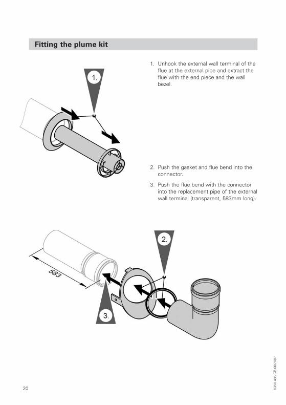
Fitting the plume kit
1. Unhook the external wall terminal of theflue at the external pipe and extract theflue with the end piece and the wallbezel.
2. Push the gasket and flue bend into theconnector.
3. Push the flue bend with the connectorinto the replacement pipe of the externalwall terminal (transparent, 583mm long).
21
Fitting the plume kit (cont.)
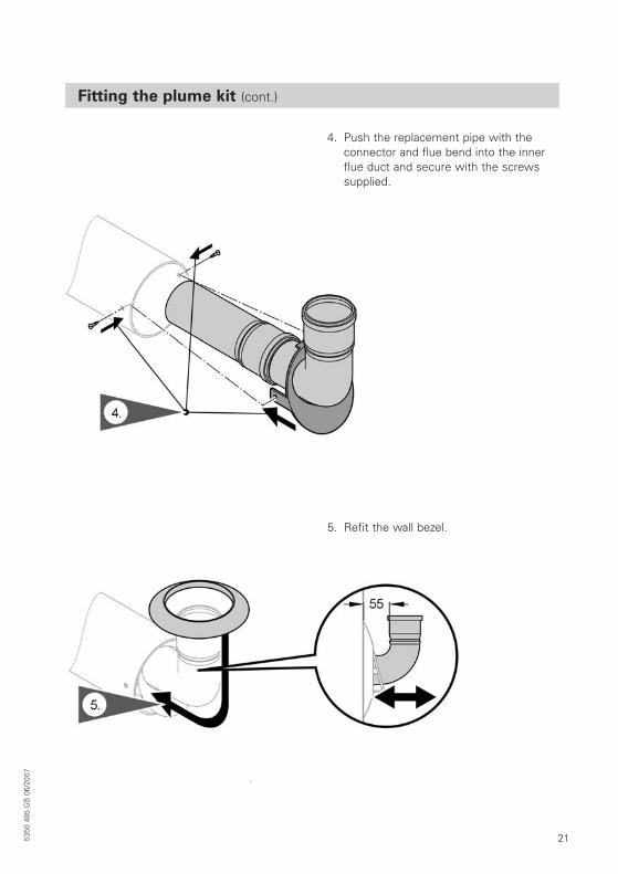
4. Push the replacement pipe with the connector and flue bend into the innerflue duct and secure with the screws supplied.
5. Refit the wall bezel.
5350
485
GB
06/
2007
22 5350
485
GB
06/
2007
Fitting the plume kit (cont.)
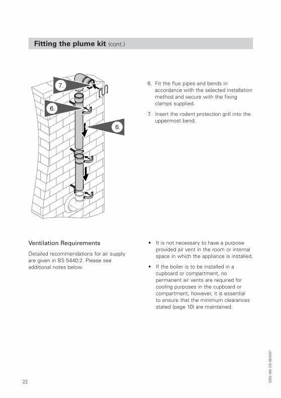
6. Fit the flue pipes and bends in accordance with the selected installationmethod and secure with the fixingclamps supplied.
7. Insert the rodent protection grill into theuppermost bend.
Ventilation Requirements
Detailed recommendations for air supplyare given in BS 5440:2. Please see additional notes below.
• It is not necessary to have a purposeprovided air vent in the room or internalspace in which the appliance is installed.
• If the boiler is to be installed in a cupboard or compartment, no permanent air vents are required forcooling purposes in the cupboard orcompartment, however, it is essential to ensure that the minimum clearancesstated (page 10) are maintained.
23
Hydraulic connections
Heating System (typical system designs)
• The Vitodens 200-W is designed for connection to sealed central heatingwater systems only.
• A sealed system must only be filled by acompetent person.
Combination boiler
NoteThe boiler incorporates an internal bypassto ensure adequate water flow. Certain thermostatic radiator valve manufacturersmay require that a bypass valve is fitted in addition to the integral by pass.
Specifications as to the individual requirements should be sought prior to installation.
Filling Loop
This boiler is not fitted or supplied with afilling loop. Any filling loop being fittedshould comply with the water supply(water fittings) regulations 1999 SectionG24.1 and G24.2. A filling loop should befitted at some point to allow the CH systemto be filled.
5350
485
GB
06/
2007
24 5350
485
GB
06/
2007
Hydraulic connections
Hydraulic circuits
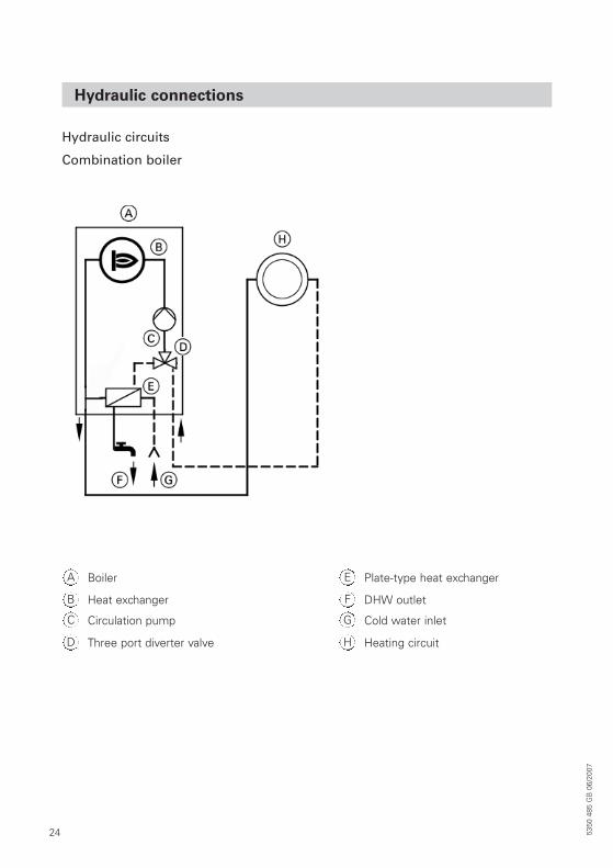
Combination boiler
BoilerA
Heat exchangerB
Circulation pumpC
Three port diverter valveD
Plate-type heat exchangerE
DHW outletF
Cold water inletG
Heating circuitH
25
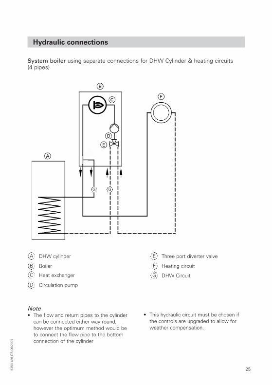
Hydraulic connections
System boiler using separate connections for DHW Cylinder & heating circuits (4 pipes)
DHW cylinderA
BoilerB
Heat exchangerC
Circulation pumpD
Three port diverter valveE
Heating circuitF
DHW CircuitG
G G
Note• The flow and return pipes to the cylinder
can be connected either way round,however the optimum method would beto connect the flow pipe to the bottomconnection of the cylinder
• This hydraulic circuit must be chosen ifthe controls are upgraded to allow forweather compensation.
5350
485
GB
06/
2007
26 5350
485
GB
06/
2007
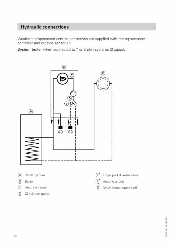
Hydraulic connections
Weather compensated control instructions are supplied with the replacement controller and outside sensor kit.
System boiler when connected to Y or S plan systems (2 pipes).
DHW cylinderA
BoilerB
Heat exchangerC
Circulation pumpD
Three port diverter valveE
Heating circuitF
DHW circuit capped offG
27
Gas and electric supply
Gas supply
• The Gas Supply should be checked at the installation planning stage in order to establish the availability of an adequate supply of gas.
• A gas meter can only be connected bythe gas supplier or their contractor.
• An existing meter and / or pipeworkshould be of sufficient size to carry the maximum boiler input plus thedemand of any other installed appliance.(BS 6891: 1988).
• The governor at the meter must give a constant outlet pressure of 21 mbar +/- 1mbar when the appliance is running.
• The gas supply line should be purged.WARNING: Before purging open alldoors and windows, also extinguish anycigarettes, pipes and any other nakedlights.
• The complete installation must be tested for gas soundness.
Electricity supply
• Wiring external to the appliance must bein accordance with BS 7671 (the currentI.E.E Wiring Regulations) for electricalinstallation.
• The mains cable must be at least 0.75mm 2 (24/0.2 mm) PVC insulated to BS 6500 table 16.
• WARNING: THIS APPLIANCE MUST BEEARTHED. (Failure to provide a satisfactory earth connection would be a safety hazard and may also result inappliance malfunction).
• The method of connection to the mains supply must facilitate completeelectrical isolation of the appliance.Either a 3A fused three pin plug andunswitched shuttered socket outlet,both complying with BS 1363, or a 3Afused double pole switch having a 3mmcontact separation in both poles andserving only the boiler (and its externalcontrols) may be used.
5350
485
GB
06/
2007
28 5350
485
GB
06/
2007
Electrical connections
Electrical Connections
Both combination and system boilersrequire a permanent live 240V supply.
Combination boiler: Room temperature control is achieved by connecting aswitched live 240V supply to the boiler.
System boiler: For Y & S Plan systems a switched live 240V supply is required to be connected to the boiler. A Viessmanncylinder sensor is a thermistor and is connected directly to the boiler. Room temperature control is achieved by connecting a 240V switched live supply to the boiler.
External controls
To ensure optimum performance,Viessmann offer a range of external controls (i.e. weather compensationVitotronic 200). However the appliance may be used with any certified 240Vroom thermostat.
Internal controls
The Vitodens 200-W is supplied fitted withan internal Vitotronic HC2 7 Day controllerfor CH and DHW on both the combinationand system boiler models.
29
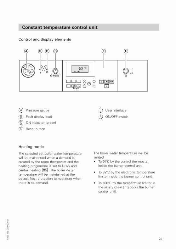
Constant temperature control unit
Control and display elements
Heating mode
The selected set boiler water temperaturewill be maintained when a demand is created by the room thermostat and theheating programme is set to DHW and central heating . The boiler water temperature will be maintained at thedefault frost protection temperature whenthere is no demand.
The boiler water temperature will be limited:• To 74ºC by the control thermostat
inside the burner control unit.
• To 82ºC by the electronic temperaturelimiter inside the burner control unit.
• To 100ºC by the temperature limiter inthe safety chain (interlocks the burnercontrol unit).
Pressure gaugeA
Fault display (red)B
ON indicator (green)C
Reset buttonD
User interfaceE
ON/OFF switchF
5350
485
GB
06/
2007
30 5350
485
GB
06/
2007
Constant temperature control unit (cont.)
DHW heating with gas fired combi boilers
If the flow switch detects that hot water isbeing drawn (>3 l/min) then the burner, cir-culation pump and 3-way valve areswitched on or changed over.
The burner modulates according to theDHW outlet temperature (max. 57ºC) and is limited by the temperature limiter (82ºC)on the primary side.
DHW heating with gas fired system boilers - utilising Viessmann DHW sensor
The burner, the circulation pump and the 3-way valve are started or changed over ifthe cylinder temperature falls 2.5 K belowthe set cylinder temperature.
In the delivered condition, the set boilerwater temperatures is 20K higher than the set DHW temperature (adjustable viacoding address “60“). The burner will beswitched OFF and the circulation pump run-on time will begin, if the actual cylinder temperature exceeds the set cylinder by 2.5K.
31
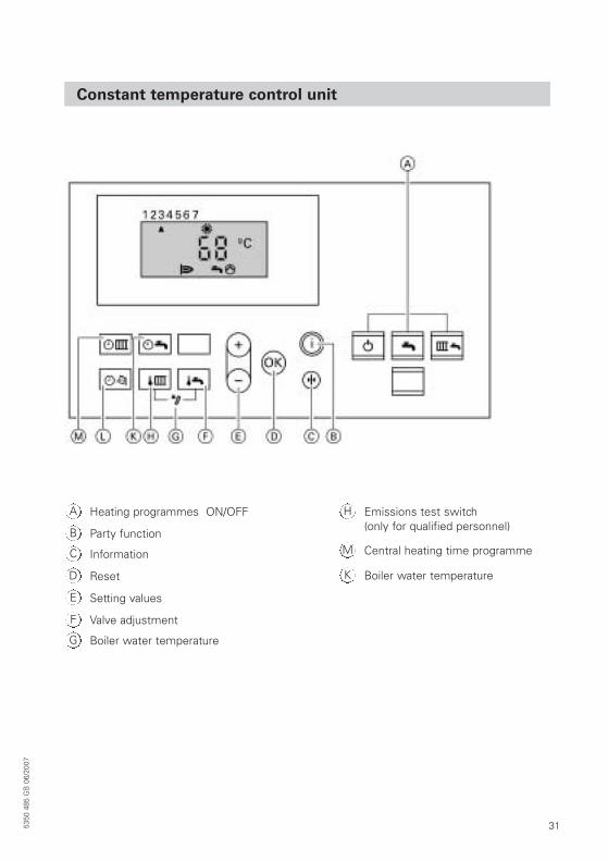
Constant temperature control unit
Heating programmes ON/OFFA
Party functionB
InformationC
ResetD
Setting valuesE
Valve adjustmentF
Boiler water temperatureG
Emissions test switch (only for qualified personnel)
H
Central heating time programmeM
Boiler water temperatureK
5350
485
GB
06/
2007
32 5350
485
GB
06/
2007
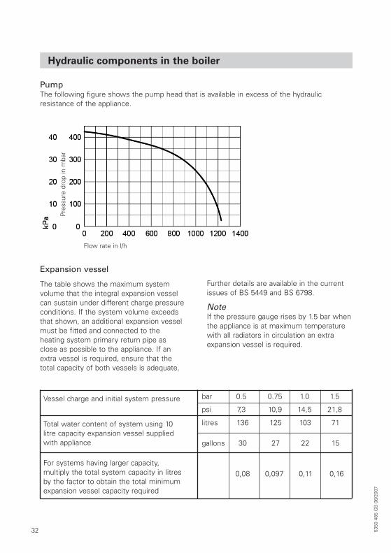
Hydraulic components in the boiler
PumpThe following figure shows the pump head that is available in excess of the hydraulic resistance of the appliance.
Expansion vessel
The table shows the maximum system volume that the integral expansion vesselcan sustain under different charge pressureconditions. If the system volume exceedsthat shown, an additional expansion vesselmust be fitted and connected to the heating system primary return pipe asclose as possible to the appliance. If anextra vessel is required, ensure that thetotal capacity of both vessels is adequate.
Further details are available in the currentissues of BS 5449 and BS 6798.
NoteIf the pressure gauge rises by 1.5 bar whenthe appliance is at maximum temperaturewith all radiators in circulation an extraexpansion vessel is required.
Vessel charge and initial system pressure bar 0.5 0.75 1.0 1.5
psi 7,3 10,9 14,5 21,8
Total water content of system using 10litre capacity expansion vessel suppliedwith appliance
For systems having larger capacity, multiply the total system capacity in litresby the factor to obtain the total minimumexpansion vessel capacity required
litres 136 125 103 71
gallons 30 27 22 15
0,08 0,097 0,11 0,16
Pres
sure
dro
p in
mba
r
Flow rate in l/h
335350
485
GB
06/
2007
Installation of boiler
Unpacking the appliance
The appliance is supplied in 2 separate packages plus any optional flue packages. Check theavailability and contents of each package before commencing the installation.
Boiler package
Combi boiler• Boiler (assembled) with control fitted• 5 shut-off valves + CH and Gas pipe tails• Wall mounting fixture• 2 wall plugs and 2 screws• Installation template• Installation instructions• Service instructions• User instructions• Warranty registration
System boiler• Boiler (assembled) with control fitted• 3 shut-off valves + CH and Gas pipe tails• 2 connection elbows• Wall mounting fixture• 2 wall plugs and 2 screws• Installation template• Installation instructions• Service instructions• User instructions• Warranty registration
Safety lifting advice
When handling or lifting the boiler body always use safe techniques - keep your back straight,bend your knees, don’t twist - move your feet, avoid bending forwards and sideways andkeep the load as close to your body as possible. Always ensure that the lift weight is withinyour own individual capability, if in doubt seek advice.
Where possible transport the boiler using a sack truck or other suitable trolley.
Always grip the boiler firmly, and before lifting feel where the weight is concentrated to,establish the centre of gravity, repositioning yourself as necessary before carrying out the lift.

34 5350
485
GB
06/
2007
Preparing the connections
NoteFor dimensions for on-site preparations of the gas and water connections see “OverallAppliance Dimensions“ on page 9
1. Prepare the hydraulic connections.
2. Clean and flush the heating systemto BS 7593. Use only the following approved additives.
Sentinel or Fernox• Anti-scaling• Anti-bacterial• Anti-freeze
- Glycol (30% max)• Anti-corrosion• Cleaner
The use of non approved additives willinvalidate the warranty on this product.
Do not use non approved additives or anychemicals from the following list.
• Boiler noise silencer• Leak sealer• Fuel, Oil, Grease, Washing powder
/liquid• Pipe jointing compound (like boss white
or boss green, Sentinel)• Anti-blockage
NoteAdditive combinations are permitted only ifapproved additive suppliers recommend itand always according to suppliers’ dosagerecommendation.
3. Prepare gas connection to BS 6891
4. Prepare the electrical connections• Mains cable: H05V2V2-F 3 G
0.75 mm2, 230 V~, 50 Hz.
A 1.5m power cable is part of the standard delivery.
• Accessory cables: H05V2V2-F 3 G0.75 mm2 for connection of room temperature control and DHW cylinder control (system boiler).
355350
485
GB
06/
2007
Wall mounting bracket installation
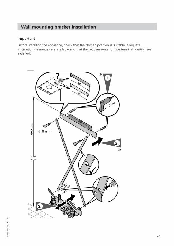
Important
Before installing the appliance, check that the chosen position is suitable, adequate installation clearances are available and that the requirements for flue terminal position aresatisfied.
36 5350
485
GB
06/
2007
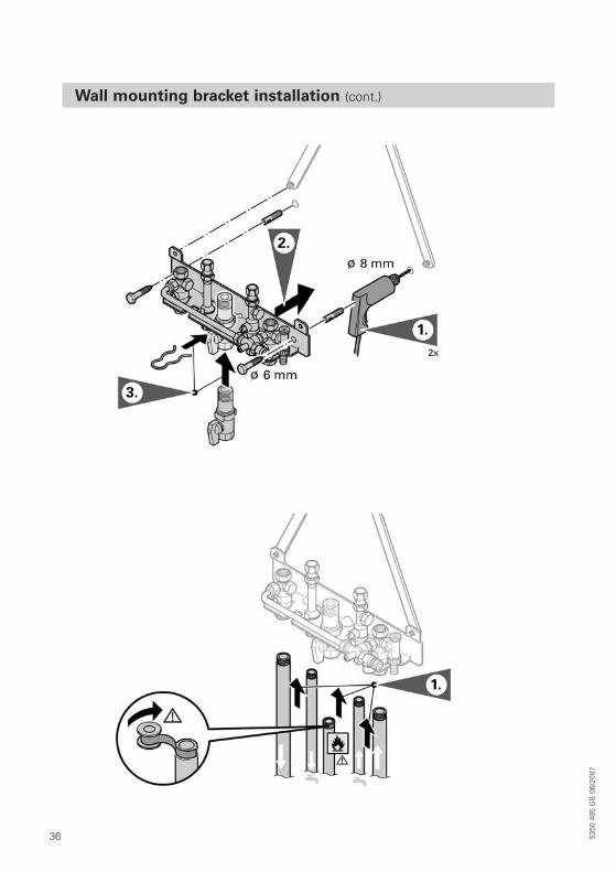
Wall mounting bracket installation (cont.)
375350
485
GB
06/
2007
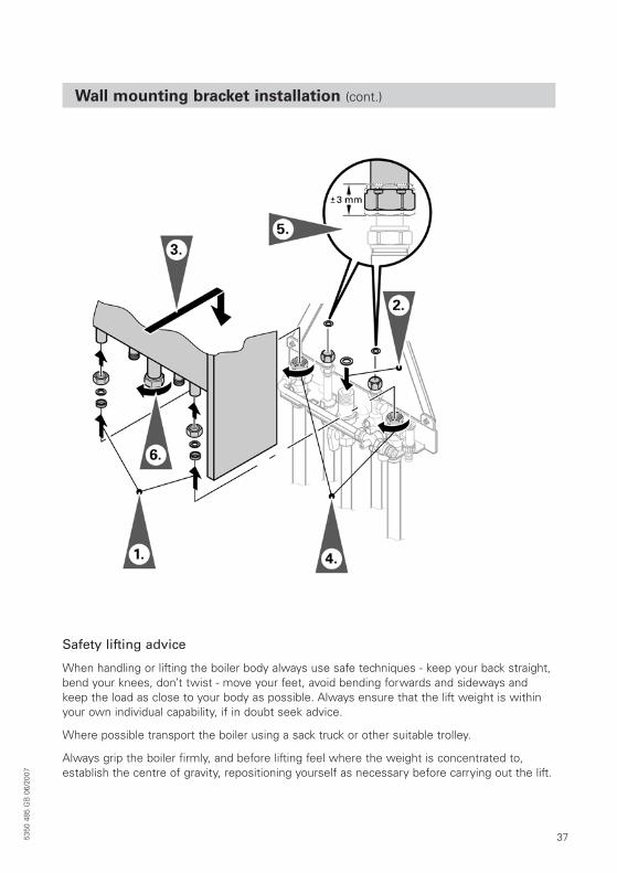
Wall mounting bracket installation (cont.)
Safety lifting advice
When handling or lifting the boiler body always use safe techniques - keep your back straight,bend your knees, don’t twist - move your feet, avoid bending forwards and sideways andkeep the load as close to your body as possible. Always ensure that the lift weight is withinyour own individual capability, if in doubt seek advice.
Where possible transport the boiler using a sack truck or other suitable trolley.
Always grip the boiler firmly, and before lifting feel where the weight is concentrated to,establish the centre of gravity, repositioning yourself as necessary before carrying out the lift.
38
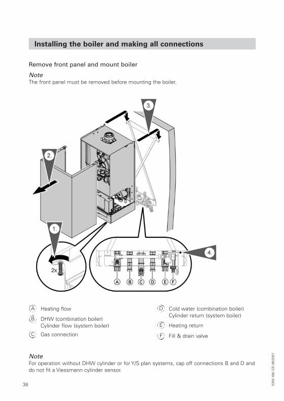
Installing the boiler and making all connections
Remove front panel and mount boiler
NoteThe front panel must be removed before mounting the boiler.
NoteFor operation without DHW cylinder or for Y/S plan systems, cap off connections B and D anddo not fit a Viessmann cylinder sensor.
Heating flowA
DHW (combination boiler)Cylinder flow (system boiler)
B
Gas connectionC
Cold water (combination boiler)Cylinder return (system boiler)
D
Heating returnE
Fill & drain valveF
5350
485
GB
06/
2007
395350
485
GB
06/
2007
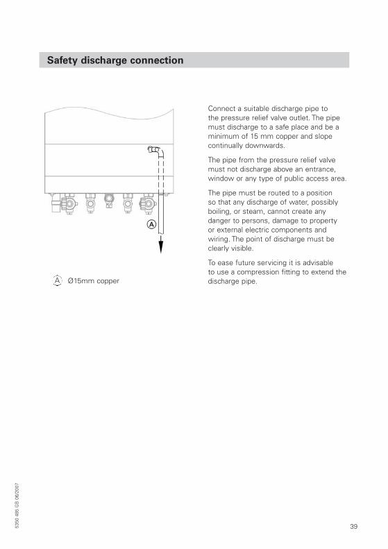
Safety discharge connection
Connect a suitable discharge pipe to the pressure relief valve outlet. The pipemust discharge to a safe place and be a minimum of 15 mm copper and slope continually downwards.
The pipe from the pressure relief valvemust not discharge above an entrance,window or any type of public access area.
The pipe must be routed to a position so that any discharge of water, possiblyboiling, or steam, cannot create any danger to persons, damage to property or external electric components andwiring. The point of discharge must beclearly visible.
To ease future servicing it is advisable to use a compression fitting to extend thedischarge pipe.Ø15mm copperA
40 5350
485
GB
06/
2007
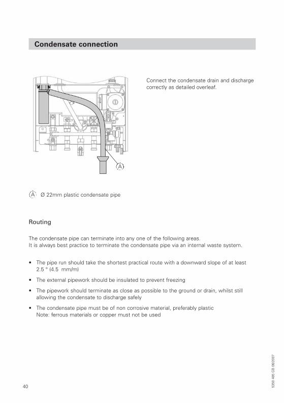
Condensate connection
Routing
The condensate pipe can terminate into any one of the following areas.It is always best practice to terminate the condensate pipe via an internal waste system.
• The pipe run should take the shortest practical route with a downward slope of at least 2.5 ° (4.5 mm/m)
• The external pipework should be insulated to prevent freezing
• The pipework should terminate as close as possible to the ground or drain, whilst stillallowing the condensate to discharge safely
• The condensate pipe must be of non corrosive material, preferably plasticNote: ferrous materials or copper must not be used
Ø 22mm plastic condensate pipeA
A
Connect the condensate drain and dischargecorrectly as detailed overleaf.
415350
485
GB
06/
2007
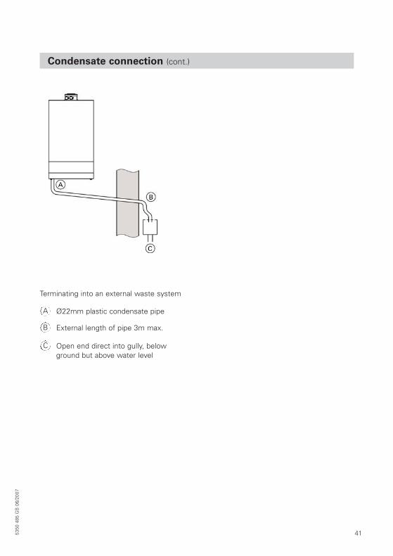
Condensate connection (cont.)
Ø22mm plastic condensate pipeA
External length of pipe 3m max.B
Open end direct into gully, belowground but above water level
C
Terminating into an external waste system
42 5350
485
GB
06/
2007
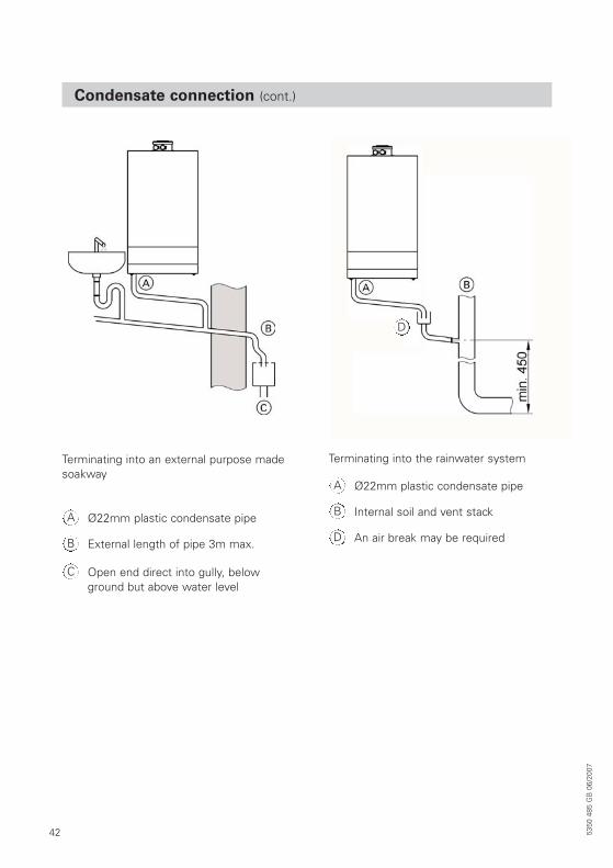
Condensate connection (cont.)
Ø22mm plastic condensate pipeA
External length of pipe 3m max.B
Open end direct into gully, belowground but above water level
C
Terminating into an external purpose madesoakway
Ø22mm plastic condensate pipeA
Internal soil and vent stackB
An air break may be requiredD
D
Terminating into the rainwater system
435350
485
GB
06/
2007
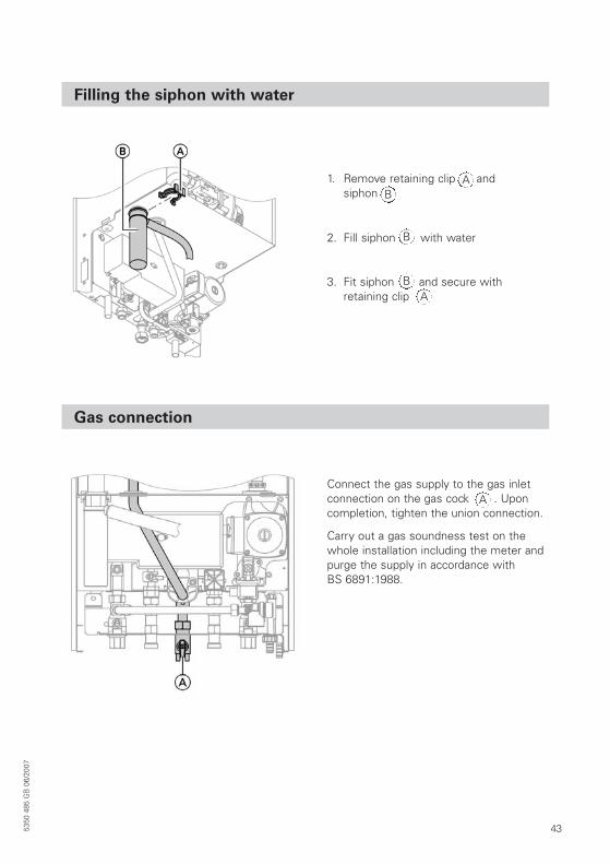
Filling the siphon with water
Gas connection
1. Remove retaining clip and siphon
AB
2. Fill siphon with waterB
3. Fit siphon and secure with retaining clip
BA
Connect the gas supply to the gas inletconnection on the gas cock . Uponcompletion, tighten the union connection.
Carry out a gas soundness test on thewhole installation including the meter andpurge the supply in accordance with BS 6891:1988.
A
44
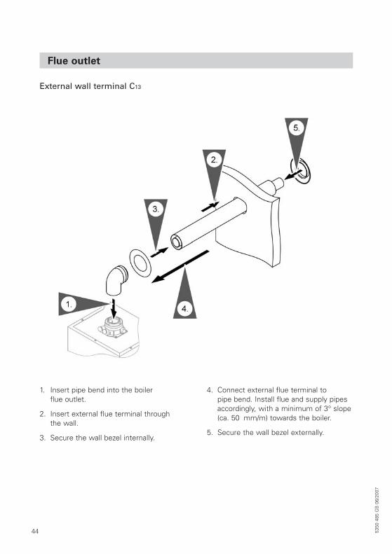
Flue outlet
External wall terminal C13
1. Insert pipe bend into the boiler flue outlet.
2. Insert external flue terminal through the wall.
3. Secure the wall bezel internally.
4. Connect external flue terminal to pipe bend. Install flue and supply pipesaccordingly, with a minimum of 3° slope(ca. 50 mm/m) towards the boiler.
5. Secure the wall bezel externally.
5350
485
GB
06/
2007
455350
485
GB
06/
2007
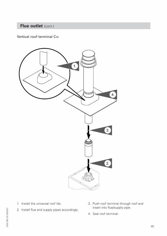
Flue outlet (cont.)
Vertical roof terminal C33
1. Install the universal roof tile.
2. Install flue and supply pipes accordingly.
3. Push roof terminal through roof andinsert into flue/supply pipe.
4. Seal roof terminal.
46
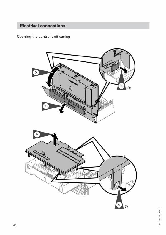
Electrical connections
Opening the control unit casing
5350
485
GB
06/
2007
475350
485
GB
06/
2007
Electrical connections
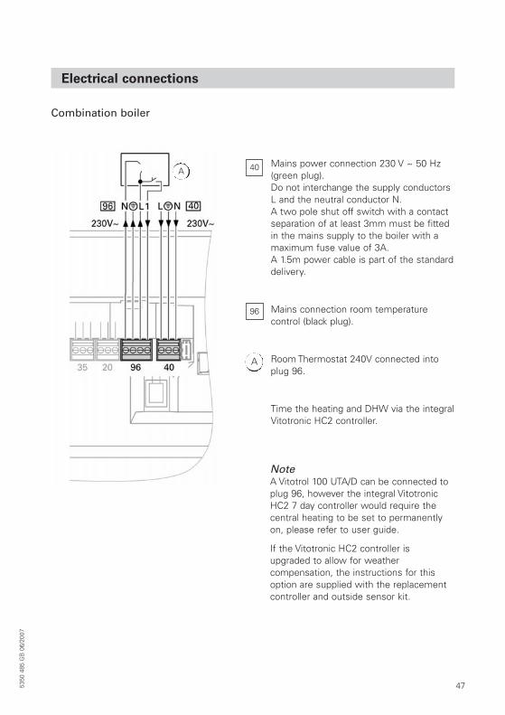
Combination boiler
Mains power connection 230 V ~ 50 Hz(green plug).Do not interchange the supply conductorsL and the neutral conductor N.A two pole shut off switch with a contactseparation of at least 3mm must be fittedin the mains supply to the boiler with amaximum fuse value of 3A.A 1.5m power cable is part of the standarddelivery.
Mains connection room temperature control (black plug).
Room Thermostat 240V connected intoplug 96.
Time the heating and DHW via the integralVitotronic HC2 controller.
40
96
A
A
NoteA Vitotrol 100 UTA/D can be connected toplug 96, however the integral VitotronicHC2 7 day controller would require the central heating to be set to permanentlyon, please refer to user guide.
If the Vitotronic HC2 controller is upgraded to allow for weather compensation, the instructions for thisoption are supplied with the replacementcontroller and outside sensor kit.
48
Electrical connections (cont.)
Separate hydraulic connections for DHWcylinder and heating circuits (4 pipes).
• The Viessmann low voltage DHW cylinder sensor must be used.
• The low voltage DHW cylinder sensormust be attached to the cylinder bysecure means to ensure good contactis made with the cylinder itself, not theinsulation, or fitted into a purpose madepocket.
• The low voltage DHW cylinder sensorconnects to plugs in the cable harnesspictured on page 56.
• Connect permanent mains supply androom thermostat (as combination boiler previous page).
NoteIf the Vitotronic HC2 controller is upgraded to allow for weather compensation the instructions for thisoption are supplied with the replacementcontroller and outside sensor kit.
• The DHW will always take priority overthe central heating when timed demandis selected.
• Time the heating and DHW via the integral Vitotronic HC2 controller.
NoteWhere an unvented hot water cylinder is used the safety thermostat connected to the cylinder that controls the 2-port safety valve (requirement for G3 of thebuilding regulations) can be operated by an independent remote timer or via aninternal H1 or H2, or external H1Viessmann accessory.
Along with other functions the H1, H2,internal /H1 external accessories when connected provide the option of a timed240V output. Follow the installation instructions supplied with the accessory.
Plug 28 on the H1 extension must be usedto connect the 2 port safety valve via thecylinder high limit thermostat. TheVitotronic internal boiler control must beset to external cylinder loading pump toactivate the timed 240V supply.
This is done via coding address 53 in coding 2.
NoteA Vitotrol 100 UTA/D can be connected toplug 96, however the integral VitotronicHC2 7 day controller would require the central heating to be set to permanentlyon, please refer to user guide.
5350
485
GB
06/
2007
495350
485
GB
06/
2007
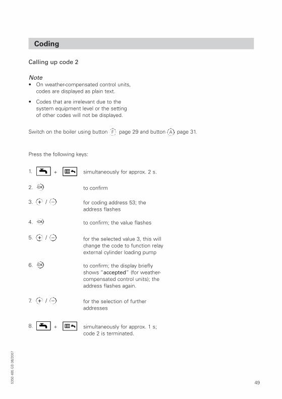
Coding
Calling up code 2
Note• On weather-compensated control units,
codes are displayed as plain text.
• Codes that are irrelevant due to the system equipment level or the setting of other codes will not be displayed.
Press the following keys:
Switch on the boiler using button page 29 and button page 31.
1. simultaneously for approx. 2 s.+
/
8. simultaneously for approx. 1 s;code 2 is terminated.
+
2. to confirmOK
OK
3. for coding address 53; the address flashes
+ _
/5. for the selected value 3, this willchange the code to function relayexternal cylinder loading pump
+ _
/7. for the selection of furtheraddresses
+ _
4. to confirm; the value flashes
OK6. to confirm; the display brieflyshows “accepted” (for weather-compensated control units); theaddress flashes again.
F A
50
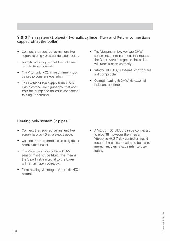
Y & S Plan system (2 pipes) (Hydraulic cylinder Flow and Return connectionscapped off at the boiler)
• Connect the required permanent livesupply to plug 40 as combination boiler.
• An external independent twin channelremote timer is used.
• The Vitotronic HC2 integral timer mustbe set to constant operation.
• The switched live supply from Y & Splan electrical configurations (that con-trols the pump and boiler) is connectedto plug 96 terminal 1.
• The Viessmann low voltage DHW sensor must not be fitted, this meansthe 3 port valve integral to the boiler will remain open correctly.
• Vitotrol 100 UTA/D external controls arenot compatible.
• Control heating & DHW via externalindependent timer.
Heating only system (2 pipes)
• Connect the required permanent livesupply to plug 40 as previous page.
• Connect room thermostat to plug 96 ascombination boiler.
• The Viessmann low voltage DHW sensor must not be fitted, this meansthe 3 port valve integral to the boiler will remain open correctly.
• Time heating via integral Vitotronic HC2control.
• A Vitotrol 100 UTA/D can be connectedto plug 96, however the integralVitotronic HC2 7 day controller wouldrequire the central heating to be set topermanently on, please refer to userguide.
5350
485
GB
06/
2007
515350
485
GB
06/
2007
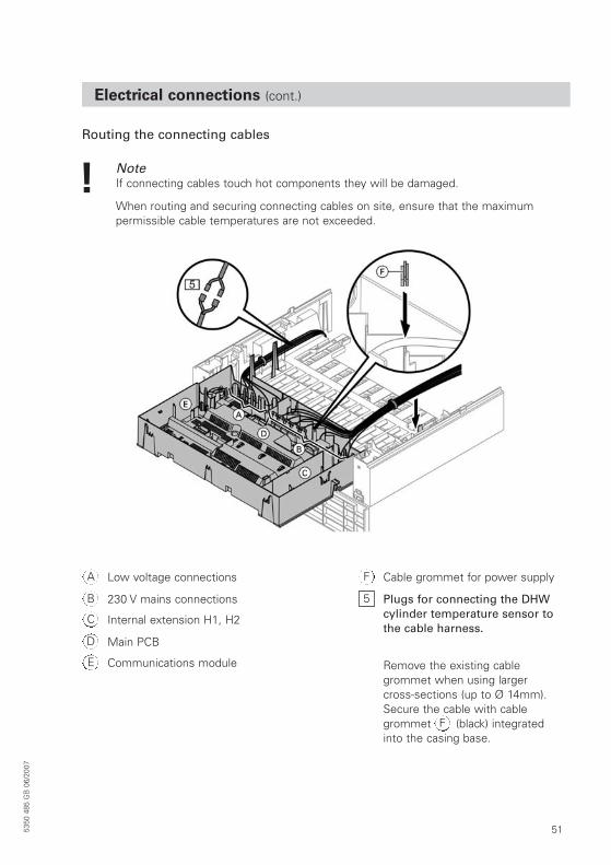
Electrical connections (cont.)
Routing the connecting cables
NoteIf connecting cables touch hot components they will be damaged.
When routing and securing connecting cables on site, ensure that the maximum permissible cable temperatures are not exceeded.
Low voltage connectionsA
230 V mains connectionsB
Internal extension H1, H2C
Main PCBD
Communications moduleE
Cable grommet for power supplyF
Plugs for connecting the DHWcylinder temperature sensor tothe cable harness.
Remove the existing cable grommet when using largercross-sections (up to Ø 14mm).Secure the cable with cablegrommet (black) integrated into the casing base.
5
F
52
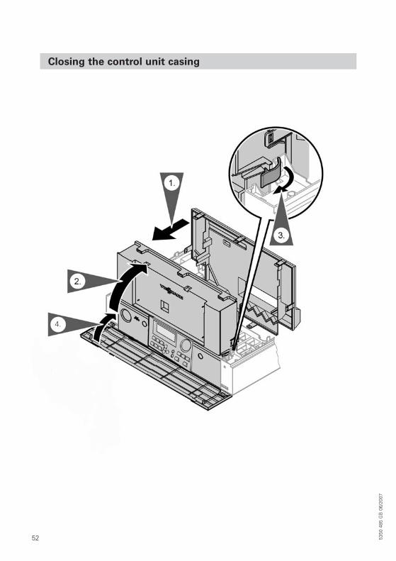
Closing the control unit casing
5350
485
GB
06/
2007
4.
535350
485
GB
06/
2007
Further details regarding the individual steps
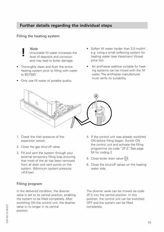
Filling the heating system
NoteUnsuitable fill water increases thelevel of deposits and corrosionand may lead to boiler damage.
• Thoroughly clean and flush the entireheating system prior to filling with waterto BS7593
• Only use fill water of potable quality.
• Soften fill water harder than 3.0 mol/m3 ,e.g. using a small softening system forheating water (see Viessmann Vitosetprice list).
• An antifreeze additive suitable for heat-ing systems can be mixed with the fillwater. The antifreeze manufacturermust verify its suitability.
1. Check the inlet pressure of the expansion vessel.
2. Close the gas shut-off valve.
3. Fill and vent the system through yourexternal temporary filling loop ensuringthat most of the air has been removedfrom all drain and vent points on thesystem. (Minimum system pressure>0.8 bar).
4. If the control unit was already switchedON before filling began: Switch ON the control unit and activate the fillingprogramme via code “2F:2”. See page54 for coding 2
5. Close boiler drain valve .
6. Close the shut-off valves on the heatingwater side.
A
Filling program
In the delivered condition, the diverter valve is set to its central position, enablingthe system to be filled completely. Afterswitching ON the control unit, the divertervalve is no longer in its central position.
The diverter vavle can be moved via code2F:2 into the central position. In this position, the control unit can be switchedOFF and the system can be filled completely.
54
Further details regarding individual steps (cont.)
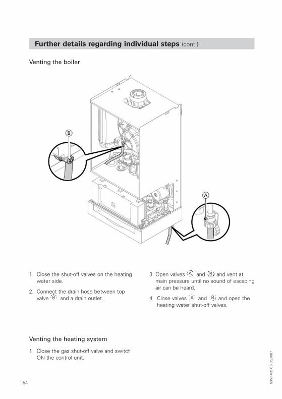
Venting the boiler
1. Close the shut-off valves on the heatingwater side.
2. Connect the drain hose between topvalve and a drain outlet.
3. Open valves and and vent atmain pressure until no sound of escapingair can be heard.
4. Close valves and and open theheating water shut-off valves.
B
A B
A B
1. Close the gas shut-off valve and switchON the control unit.
Venting the heating system
5350
485
GB
06/
2007
555350
485
GB
06/
2007
Venting
Venting program
During the venting program, the circulationpump will be alternately switched ON andOFF for 30 s respectively over a period of20 min. For a certain period, the divertervalve is alternately set towards heating andDHW heating, The burner is switched OFFduring the venting programme.
The venting program is activated via code “2F:1” page 49. The program is automatically disabled after 20 min and coding address “2F” is set to “0”.
Filling with the control unit switched ON
If the system is to be filled with the controlunit switched ON, the diverter valve will bemoved to its central position via code“2F:2” and the pump will be started.
The burner shuts down if this function isenabled via coding address “2F”. The program is automatically disabled after 20min and coding address “2F” is set to “0”.
56 5350
485
GB
06/
2007
Checking diaphragm expansion vessel and system pressure
NoteCarry out this test on a cold system.
1. Drain the system, or close the cap valveon the expansion vessel and reduce the pressure, until the pressure gaugeindicates “0”.
2. If the inlet pressure of the expansionvessel is lower than the pre-charge pressure of 6.75 bar, top up until theinlet pressure is raised to 6.75 bar.
3. Top up your heating system with waterand vent until the filling pressure of acooled system is 0.1 to 0.2 bar higherthan the inlet pressure of the diaphragm expansion vessel.Permiss. operating pressure: 2.5 bar
Checking the gas type
Wobbe index ranges
Gas type Wobbe index rangekWh/m3 MJ/m3
Delivered conditionNatural gas E (G20) 12.0 to 16.1 43.2 to 58.0
After conversionLPG P 20.3 to 21.3 72.9 to 76.8
The boiler is equipped with an electroniccombustion control unit which adjusts theburner for optimum combustion in accordance with the prevailing gas quality.
• The boiler can be operated with naturalgas in the Wobbe index range 10.0 to16.1 kWh/m3 (36.0 to 58/0 MJ/m3) without conversion.
• Adjust the burner for operation withLPG (see “Gas type conversion” overleaf).
1. Determine the gas type and Wobbeindex (Wo) by asking your local mainsgas or LPG supplier.
2. Convert the burner for operation withLPG (see overleaf).
3. Record the gas type in the benchmarkcommissioning check list on page 71.
575350
485
GB
06/
2007
Gas supply
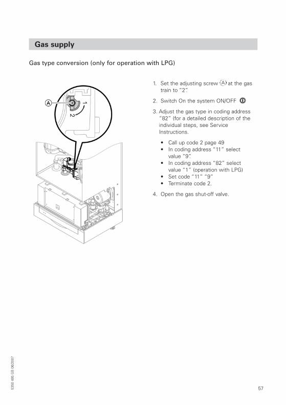
Gas type conversion (only for operation with LPG)
1. Set the adjusting screw at the gastrain to “2”.
2. Switch On the system ON/OFF
3. Adjust the gas type in coding address“82” (for a detailed description of theindividual steps, see ServiceInstructions.
• Call up code 2 page 49• In coding address “11” select
value “9”.• In coding address “82” select
value “1” (operation with LPG)• Set code “11” “9”• Terminate code 2.
4. Open the gas shut-off valve.
A
58 5350
485
GB
06/
2007
Gas supply
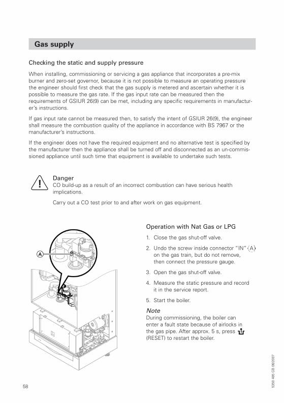
Operation with Nat Gas or LPG
1. Close the gas shut-off valve.
2. Undo the screw inside connector “IN”on the gas train, but do not remove,then connect the pressure gauge.
3. Open the gas shut-off valve.
4. Measure the static pressure and recordit in the service report.
5. Start the boiler.
NoteDuring commissioning, the boiler canenter a fault state because of airlocks inthe gas pipe. After approx. 5 s, press(RESET) to restart the boiler.
Checking the static and supply pressure
DangerCO build-up as a result of an incorrect combustion can have serious health implications.
Carry out a CO test prior to and after work on gas equipment.
When installing, commissioning or servicing a gas appliance that incorporates a pre-mix burner and zero-set governor, because it is not possible to measure an operating pressure the engineer should first check that the gas supply is metered and ascertain whether it ispossible to measure the gas rate. If the gas input rate can be measured then the requirements of GSIUR 26(9) can be met, including any specific requirements in manufactur-er’s instructions.
If gas input rate cannot be measured then, to satisfy the intent of GSIUR 26(9), the engineershall measure the combustion quality of the appliance in accordance with BS 7967 or themanufacturer’s instructions.
If the engineer does not have the required equipment and no alternative test is specified bythe manufacturer then the appliance shall be turned off and disconnected as an un-commis-sioned appliance until such time that equipment is available to undertake such tests.
A
595350
485
GB
06/
2007
Gas supply
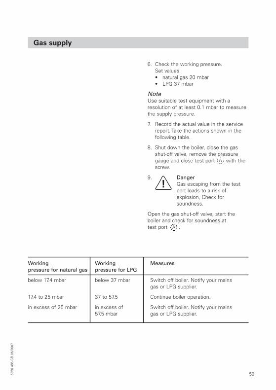
6. Check the working pressure.Set values:• natural gas 20 mbar• LPG 37 mbar
NoteUse suitable test equipment with a resolution of at least 0.1 mbar to measurethe supply pressure.
7. Record the actual value in the servicereport. Take the actions shown in the following table.
8. Shut down the boiler, close the gas shut-off valve, remove the pressuregauge and close test port with thescrew.
9. DangerGas escaping from the testport leads to a risk of explosion, Check for soundness.
Open the gas shut-off valve, start the boiler and check for soundness at test port .A
A
Working Working Measurespressure for natural gas pressure for LPG
below 17.4 mbar below 37 mbar Switch off boiler. Notify your mains gas or LPG supplier.
17.4 to 25 mbar 37 to 57.5 Continue boiler operation.
in excess of 25 mbar in excess of Switch off boiler. Notify your mains 57.5 mbar gas or LPG supplier.

60 5350
485
GB
06/
2007
Setting the maximum CH output
1. Start the boiler
2. Press and simultaneouslyuntil a value appears and flashes (e.g.“85”) and appears. In the delivered condition, this value represents 100% ofrated output. On weather compensatedcontrol units, the display additionallyshows “Max Heating Output”.
3. With select the required value in % of rated output as maximumoutput.
4. Confirm the set value with
5. Record the settings for maximum outputon the additional type plate includedwith the “technical documentation”. Affixthe type plate next to the original typeplate on top of the boiler.
NoteThe output can also be limited for DHWheating. For this, change coding address“6F” in code 2.
NoteYou can limit the maximum output for heating operation. The limit is set via the modulationrange. The max. adjustable heating output is limited by the boiler coding card.
/+ _
OK
615350
485
GB
06/
2007
Flue system check
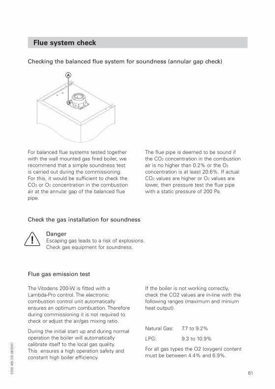
For balanced flue systems tested togetherwith the wall mounted gas fired boiler, werecommend that a simple soundness testis carried out during the commissioning.For this, it would be sufficient to check theCO2 or O2 concentration in the combustionair at the annular gap of the balanced fluepipe.
The flue pipe is deemed to be sound if the CO2 concentration in the combustionair is no higher than 0.2% or the O2
concentration is at least 20.6%. If actualCO2 values are higher or O2 values arelower, then pressure test the flue pipe with a static pressure of 200 Pa.
The Vitodens 200-W is fitted with aLambda-Pro control. The electronic combustion control unit automaticallyensures an optimum combustion. Thereforeduring commissioning it is not required tocheck or adjust the air/gas mixing ratio.
During the initial start up and during normaloperation the boiler will automatically calibrate itself to the local gas quality. This ensures a high operation safety andconstant high boiler efficiency.
If the boiler is not working correctly, check the CO2 values are in-line with thefollowing ranges (maximum and miniumheat output).
Natural Gas: 7.7 to 9.2%
LPG: 9.3 to 10.9%
For all gas types the O2 (oxygen) contentmust be between 4.4% and 6.9%.
Check the gas installation for soundness
DangerEscaping gas leads to a risk of explosions.Check gas equipment for soundness.
Checking the balanced flue system for soundness (annular gap check)
Flue gas emission test
62 5350
485
GB
06/
2007
Combustion
If the actual CO2 or O2 values lie outside their respective ranges, proceed withthe following steps:
• Check the balanced flue system for soundness, see page 66
• Check the ionisation electrode and connecting lead, see service instructions.
• Check the parameters of the combustion control unit, see service instructions.
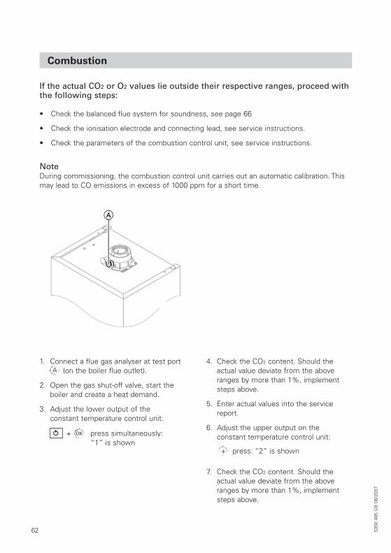
NoteDuring commissioning, the combustion control unit carries out an automatic calibration. Thismay lead to CO emissions in excess of 1000 ppm for a short time.
1. Connect a flue gas analyser at test port (on the boiler flue outlet).
2. Open the gas shut-off valve, start theboiler and create a heat demand.
3. Adjust the lower output of the constant temperature control unit:
4. Check the CO2 content. Should the actual value deviate from the aboveranges by more than 1%, implementsteps above.
5. Enter actual values into the servicereport.
6. Adjust the upper output on the constant temperature control unit:
7. Check the CO2 content. Should the actual value deviate from the aboveranges by more than 1%, implementsteps above.
OK
A
+
+
press simultaneously: “1” is shown
press: “2” is shown
635350
485
GB
06/
2007
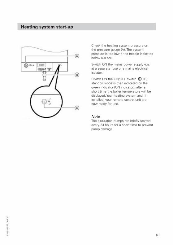
Heating system start-up
Check the heating system pressure on the pressure gauge (A). The system pressure is too low if the needle indicatesbelow 0.8 bar.
Switch ON the mains power supply e.g. at a separate fuse or a mains electrical isolator.
Switch ON the ON/OFF switch ( (C); standby mode is then indicated by thegreen indicator (ON indicator); after a short time the boiler temperature will be displayed. Your heating system and, ifinstalled, your remote control unit are now ready for use.
NoteThe circulation pumps are briefly startedevery 24 hours for a short time to preventpump damage.
64 5350
485
GB
06/
2007
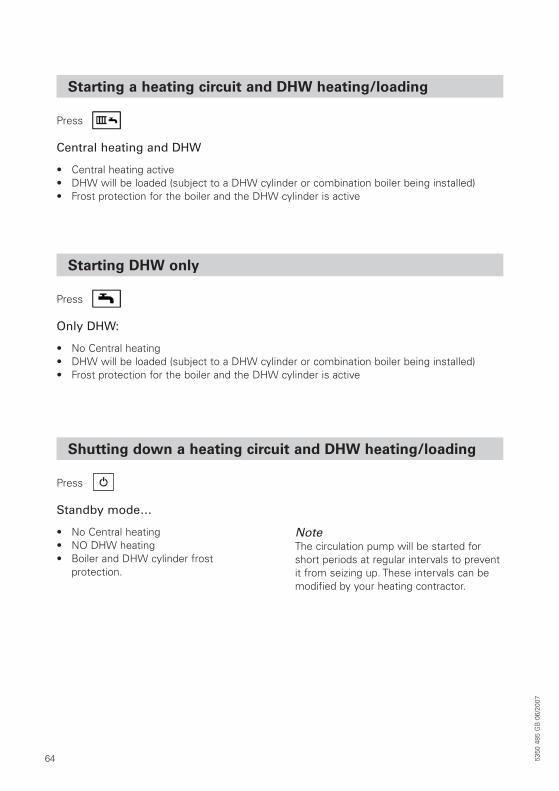
Starting a heating circuit and DHW heating/loading
Central heating and DHW
• Central heating active• DHW will be loaded (subject to a DHW cylinder or combination boiler being installed)• Frost protection for the boiler and the DHW cylinder is active
Press
Starting DHW only
Only DHW:
• No Central heating• DHW will be loaded (subject to a DHW cylinder or combination boiler being installed)• Frost protection for the boiler and the DHW cylinder is active
Press
Shutting down a heating circuit and DHW heating/loading
Standby mode…
• No Central heating• NO DHW heating• Boiler and DHW cylinder frost
protection.
NoteThe circulation pump will be started forshort periods at regular intervals to preventit from seizing up. These intervals can bemodified by your heating contractor.
Press
655350
485
GB
06/
2007
Switching the comfort function ON and OFF
Make adjustments using the appropriateroom thermostat operating instructions.
Please also note:• The heating programme selector of the
boiler control unit must be set to
• Set the boiler water temperature high enough
• There should not be a thermostatic radiator valve in the room, where theroom thermostat is installed.
The comfort function can be switched OFFwith . To save energy the comfort funtion can be timed.
NoteIf the comfort function is switched off theboiler will still provide instantaneous DHW.
Only for use with the combination boiler. The boiler is maintained at a standby temperaturewhen the comfort function is switched ON. Hot water will then be available instantly.
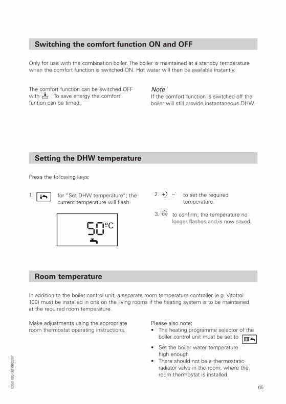
Setting the DHW temperature
Press the following keys:
1.
50°C-
for “Set DHW temperature“; the current temperature will flash
2. to set the required temperature.
+ _
3. to confirm; the temperature nolonger flashes and is now saved.
OK
Room temperature
In addition to the boiler control unit, a separate room temperature controller (e.g. Vitotrol100) must be installed in one on the living rooms if the heating system is to be maintainedat the required room temperature.
66 5350
485
GB
06/
2007
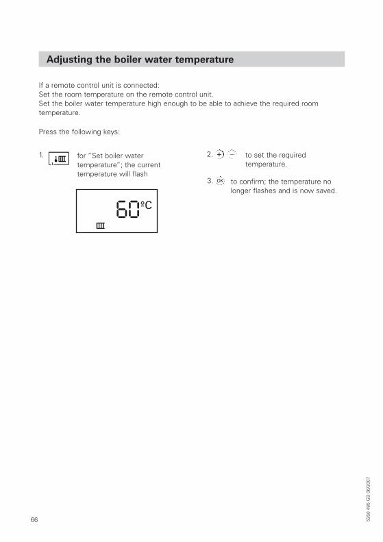
Adjusting the boiler water temperature
Press the following keys:
If a remote control unit is connected:Set the room temperature on the remote control unit.Set the boiler water temperature high enough to be able to achieve the required room temperature.
1. for “Set boiler water temperature“; the current temperature will flash
2. to set the required temperature.
+ _
3. to confirm; the temperature no longer flashes and is now saved.
OK
60°C-
675350
485
GB
06/
2007
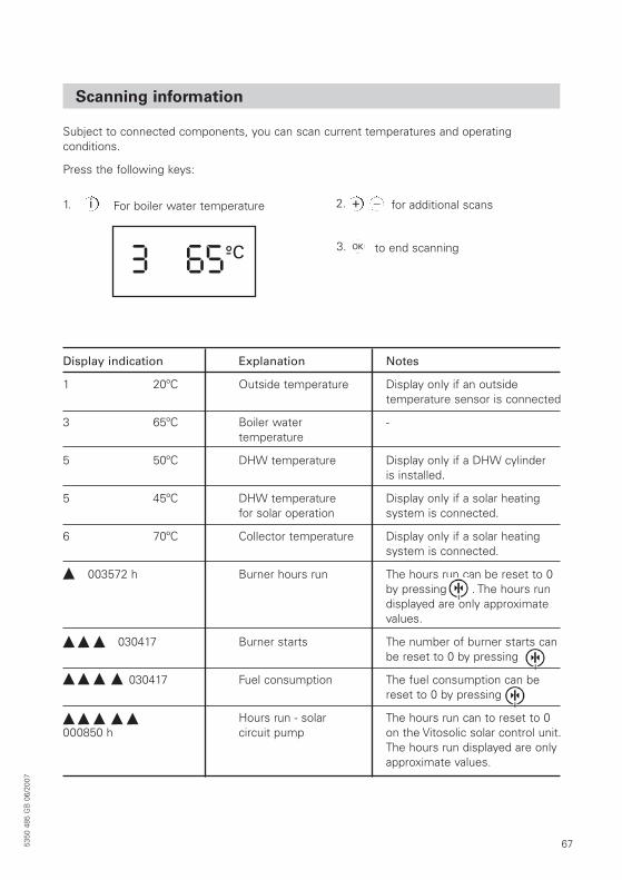
Scanning information
Subject to connected components, you can scan current temperatures and operating conditions.
Press the following keys:
Display indication Explanation Notes
1 20ºC Outside temperature Display only if an outside temperature sensor is connected
3 65ºC Boiler water -temperature
5 50ºC DHW temperature Display only if a DHW cylinderis installed.
5 45ºC DHW temperature Display only if a solar heatingfor solar operation system is connected.
6 70ºC Collector temperature Display only if a solar heatingsystem is connected.
003572 h Burner hours run The hours run can be reset to 0 by pressing . The hours run displayed are only approximate values.
030417 Burner starts The number of burner starts can be reset to 0 by pressing
030417 Fuel consumption The fuel consumption can be reset to 0 by pressing
Hours run - solar The hours run can to reset to 0000850 h circuit pump on the Vitosolic solar control unit.
The hours run displayed are only approximate values.
1.
653 °C-
For boiler water temperature 2. for additional scans+i _
3. to end scanningOK
68 5350
485
GB
06/
2007
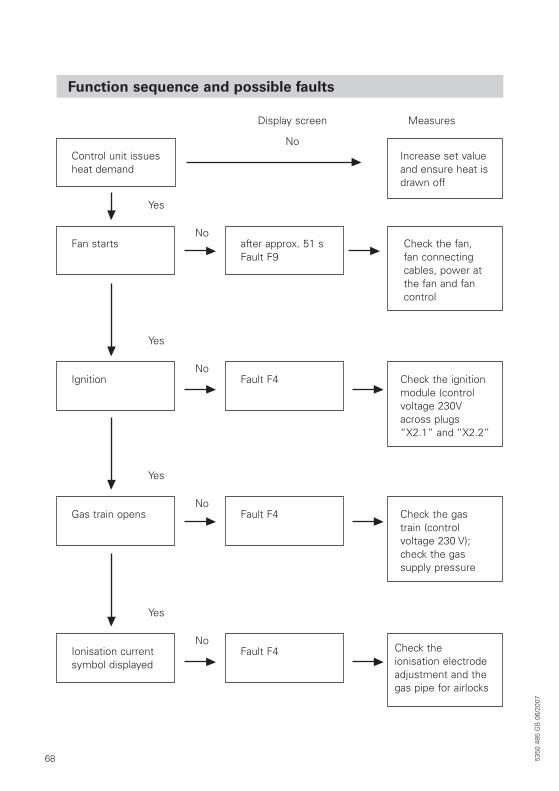
Function sequence and possible faults
Control unit issues heat demand
Increase set valueand ensure heat isdrawn off
Fan starts after approx. 51 sFault F9
Check the fan, fan connectingcables, power atthe fan and fancontrol
Display screen
No
No
Yes
Ignition Fault F4 Check the ignitionmodule (controlvoltage 230Vacross plugs“X2.1” and “X2.2”
No
Yes
Gas train opens Fault F4 Check the gastrain (control voltage 230 V);check the gas supply pressure
No
Yes
Ionisation currentsymbol displayed
Fault F4 Check the ionisation electrodeadjustment and thegas pipe for airlocks
No
Yes
Measures
695350
485
GB
06/
2007
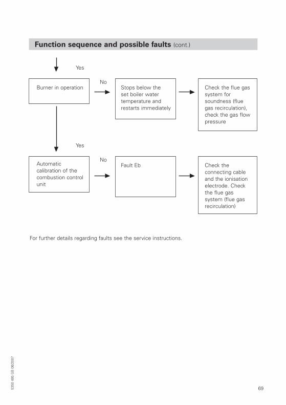
Function sequence and possible faults (cont.)
Burner in operation
For further details regarding faults see the service instructions.
Stops below the set boiler water temperature andrestarts immediately
Check the flue gassystem for soundness (fluegas recirculation),check the gas flowpressure
No
Yes
Automatic calibration of thecombustion controlunit
Fault Eb Check the connecting cableand the ionisationelectrode. Checkthe flue gas system (flue gasrecirculation)
No
Yes
70
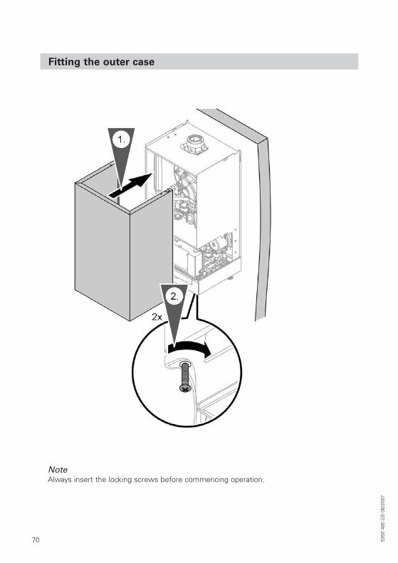
Fitting the outer case
5350
485
GB
06/
2007
NoteAlways insert the locking screws before commencing operation.

715350
485
GB
06/
2007
735350
485
GB
06/
2007
Declaration of conformity
Declaration of conformity for the Vitodens 200-W
We, Viessmann Werke GmbH&Co KG, D-35107 Allendorf, declare as sole responsible body,that the product Vitodens 200-W complies with the following standards:
EN 483 EN 55 014EN 625 EN 60 335EN 677 EN 61 000-3-2EN 13 203 EN 61 000-3-3EN 50 165
This product is designated with CE-0085 in accordance with the following Directives:
90/396/EEC 73/23/EEC89/336/EEC 92/42/EEC
This product meets the requirements of the Efficiency Directive (92/42/EEC) for condensingboilers.
The product characteristics determined as system values for the product Vitodens 200-W as part of EC type testing according to the Efficiency Directive (see specification table) can be utilised to assess the energy consumption of heating and ventilation equipment to DIN V 4701-10 which is specified by the EnEV (Germany).
Allendorf, 1 December 2006 Viessmann Werke GmbH&Co KG
pp. Manfred Sommer
74
Manufacturer’s certificate according to the 1st BlmSchV
(Germany)
Allendorf, 1 December 2006 Viessmann Werke GmbH&Co KG
pp. Manfred Sommer
We, Viessmann Werke GmbH&Co KG, D-35107 Allendorf, confirm that the product Vitodens 200-W complies with the NOx limits specified by the BlmSchV paragraph 7 (2)(Germany).
5350
485
GB
06/
2007

755350
485
GB
06/
2007
Viessmann Werke GmbH&Co KGD-35107 AllendorfTel: +49 6452 70-0Fax: +49 6452 70-2780www.viessmann.com
Viessmann LimitedHortonwood 30, Telford, TF1 7YP, GBTel: +44 (0)1952 675000Fax: +44 (0)1952 675040www.viessmann.co.uk
Applicability
Gas Fired condensing boilerType WB2B4.8 to 19.0 kWfrom serial no7248 823 7 0001…
6.5 to 26.0 kWfrom serial no7248 824 7 0001…
8.8 to 30.0 kWfrom serial no7248 826 7 00001…
8.8 to 35.0 kWfrom serial no7248 828 7 00001…
Gas Fired condensing combi boilerType WB2B6.5 to 26.0 kWfrom serial no7248 825 7 00001…
8.8 to 30.0 kWfrom serial no7248 827 0001…
8.8 to 35.0 kWfrom serial no7248 829 7 00001…
5350
485
GB
06/
2007
Sub
ject
to
tech
nica
l mod
ifica
tions
Prin
ted
on e
nviro
nmen
tally
frie
ndly
, ch
lorin
e-fr
ee b
leac
hed
pape
r


![Viessmann. VITODENS 200-W WB2C - Belmingaz.by · L_ogbq_kdb_oZjZdl_jbklbdb =Zah\uc\h^h]j_cgucdhl_e dhgkljmdlb\guclbi %b& dZl_]hjby,, 1 3 =Zah\uch^ghdhglmjgucdhl_e =Zah\ucdhf[bgbjh](https://static.fdocuments.us/doc/165x107/60fdfa83131be5238c7e0e04/viessmann-vitodens-200-w-wb2c-logbqkdbozjzdljbklbdb-zahuchhjcgucdhle.jpg)