VIESMANN VITOCAL - Viessmann · VIESMANN VITOCAL Brine/water and water/water heat pumps Single and...
216
VIESMANN VITOCAL Brine/water and water/water heat pumps Single and two-stage, 5.8 to 117.8 kW Electrically driven heat pumps for central heating and DHW heating in mono mode or dual mode heating systems VITOCAL 200-G Type BWC 201.A, BWC-M 201.A Single stage brine/water heat pump, 400 V~/230 V~. VITOCAL 300-G ■ Type BW 301.B06 to B17, BWC 301.B06 to B17, BW 301.A21 to A45 Single stage brine/water and water/water heat pump ■ Type BW 301.B06 to B17 + BWS 301.B06 to B17, BW 301.A21 to A45 + BWS 301.A21 to A45 Two-stage brine/water and water/water heat pump VITOCAL 350-G ■ Type BW 351.A, BWC 351.A Single stage brine/water and water/water heat pump ■ Type BW 351.A + BWS 351.A Two-stage brine/water and water/water heat pump VITOCAL 222-G, 242-G Type BWT 221.A/241.A, BWT-M 221.A/241.A Compact heat pump with integral DHW cylinder, 400 V~/230 V~. VITOCAL 333-G, 343-G Type BWT 331.B/341.B, BWT-NC 331.B Compact heat pump with integral DHW cylinder, 400 V~. Type BWT-NC with integral natural cooling function. 5822 541 GB 4/2014 Technical guide
Transcript of VIESMANN VITOCAL - Viessmann · VIESMANN VITOCAL Brine/water and water/water heat pumps Single and...

VIESMANN VITOCALBrine/water and water/water heat pumps
Single and two-stage, 5.8 to 117.8 kW
Electrically driven heat pumps for central heating and DHWheating in mono mode or dual mode heating systems
VITOCAL 200-G
Type BWC 201.A, BWC-M 201.ASingle stage brine/water heat pump, 400 V~/230 V~.
VITOCAL 300-G ■ Type BW 301.B06 to B17, BWC 301.B06 to B17, BW
301.A21 to A45Single stage brine/water and water/water heat pump
■ Type BW 301.B06 to B17 + BWS 301.B06 to B17, BW301.A21 to A45 + BWS 301.A21 to A45Two-stage brine/water and water/water heat pump
VITOCAL 350-G ■ Type BW 351.A, BWC 351.A
Single stage brine/water and water/water heat pump■ Type BW 351.A + BWS 351.A
Two-stage brine/water and water/water heat pump
VITOCAL 222-G, 242-G
Type BWT 221.A/241.A, BWT-M 221.A/241.ACompact heat pump with integral DHW cylinder,400 V~/230 V~.
VITOCAL 333-G, 343-G
Type BWT 331.B/341.B, BWT-NC 331.BCompact heat pump with integral DHW cylinder, 400 V~.Type BWT-NC with integral natural cooling function.
5822 541 GB 4/2014
Technical guide

Index
1. Vitocal 200-G, type BWC 201.A06to A17
1. 1 Product description ................................................................................................... 7■ Benefits ................................................................................................................. 7■ Delivered condition ............................................................................................... 7
1. 2 Specification ............................................................................................................. 8■ Specification .......................................................................................................... 8■ Dimensions ........................................................................................................... 10■ Application limits to EN 14511 .............................................................................. 11■ Curves type BWC ................................................................................................. 12■ Curves type BWC-M ............................................................................................. 17
2. Vitocal 300-G, type BW 301.B06 toB17, BWS 301.B06 to B17, BWC301.B06 to B17
2. 1 Product description ................................................................................................... 20■ Benefits of type BW, BWS .................................................................................... 20■ Delivered condition, type BW ................................................................................ 20■ Delivered condition, type BWS ............................................................................. 20■ Benefits of type BWC ............................................................................................ 21■ Delivered condition, type BWC ............................................................................. 21
2. 2 Specification ............................................................................................................. 22■ Specification for brine/water heat pumps .............................................................. 22■ Water/water heat pump specification .................................................................... 23■ Dimensions, type BW, BWS ................................................................................. 25■ Dimensions, type BWC ......................................................................................... 26■ Application limits to EN 14511 .............................................................................. 27■ Curves, type BW, BWS ......................................................................................... 28■ Curves, type BWC ................................................................................................ 33
3. Vitocal 300-G, type BW 301.A21 toA45, BWS 301.A21 to A45
3. 1 Product description ................................................................................................... 38■ Benefits ................................................................................................................. 38■ Delivered condition, type BW ................................................................................ 38■ Delivered condition, type BWS ............................................................................. 38
3. 2 Specification ............................................................................................................. 39■ Specification for brine/water heat pumps .............................................................. 39■ Specification for water/water heat pumps ............................................................. 40■ Dimensions ........................................................................................................... 42■ Application limits to EN 14511 .............................................................................. 43■ Curves ................................................................................................................... 44
4. Vitocal 350-G, type BW 351.A07,BWS 351.A07, BWC 351.A07
4. 1 Product description ................................................................................................... 47■ Benefits of type BW, BWS .................................................................................... 47■ Delivered condition, type BW ................................................................................ 47■ Delivered condition, type BWS ............................................................................. 47■ Benefits of type BWC ............................................................................................ 48■ Delivered condition, type BWC ............................................................................. 48
4. 2 Specification ............................................................................................................. 49■ Specification for brine/water heat pumps .............................................................. 49■ Dimensions, type BW 351.A07, BWS 351.A07 ..................................................... 53■ Dimensions, type BWC 351.A07 ........................................................................... 54■ Application limits to EN 14511 .............................................................................. 55■ Curves, type BW, BWS ......................................................................................... 56■ Curves, type BWC ................................................................................................ 57
5. Vitocal 350-G, type BW 351.A18,BWS 351.A18
5. 1 Product description ................................................................................................... 58■ Benefits of type BW, BWS .................................................................................... 58■ Delivered condition, type BW ................................................................................ 58■ Delivered condition, type BWS ............................................................................. 58
5. 2 Specification ............................................................................................................. 59■ Specification for brine/water heat pumps .............................................................. 59■ Specification for water/water heat pumps ............................................................. 60■ Dimensions, type BW 351.A18, BWS 351.A18 ..................................................... 61■ Application limits to EN 14511 .............................................................................. 62■ Curves, type BW, BWS ......................................................................................... 63
6. Vitocal 222-G, type BWT 221.A06to A10
6. 1 Product description ................................................................................................... 64■ Delivered condition ............................................................................................... 64
6. 2 Specification ............................................................................................................. 65■ Specification .......................................................................................................... 65■ Dimensions ........................................................................................................... 68■ Application limits to EN 14511 .............................................................................. 69■ Curves type BWT .................................................................................................. 70■ Curves, type BWT-M ............................................................................................. 73
Index
2 VIESMANN VITOCAL
5822
541
GB
7. Vitocal 242-G, type BWT 241.A06to A10
7. 1 Product description ................................................................................................... 76■ Delivered condition ............................................................................................... 76
7. 2 Specification ............................................................................................................. 78■ Specification .......................................................................................................... 78■ Dimensions ........................................................................................................... 81■ Application limits to EN 14511 .............................................................................. 82■ Curves type BWT .................................................................................................. 83■ Curves, type BWT-M ............................................................................................. 86
8. Vitocal 333-G, type BWT 331.B06to B10, BWT-NC 331.B06 to B10
8. 1 Product description ................................................................................................... 89■ Delivered condition type BWT ............................................................................... 89■ Delivered condition type BWT-NC ........................................................................ 90
8. 2 Specification ............................................................................................................. 91■ Specification .......................................................................................................... 91■ Dimensions ........................................................................................................... 94■ Application limits to EN 14511 .............................................................................. 95■ Curves type BWT, BWT-NC ................................................................................. 96
9. Vitocal 343-G, type BWT 341.B06to B10
9. 1 Product description ................................................................................................... 99■ Delivered condition ............................................................................................... 100
9. 2 Specification ............................................................................................................. 101■ Specification .......................................................................................................... 101■ Dimensions ........................................................................................................... 103■ Application limits to EN 14511 .............................................................................. 104■ Curves type BWT .................................................................................................. 105
10. DHW cylinders 10. 1 Vitocell 100-V, type CVW ......................................................................................... 108
11. Installation accessories 11. 1 Overview, installation accessories ............................................................................ 11111. 2 Ventilation unit .......................................................................................................... 115
■ Vitovent 300-F ....................................................................................................... 11511. 3 Brine circuit (primary circuit) ..................................................................................... 117
■ Sensor well set, primary circuit ............................................................................. 117■ Brine accessory pack and pump set for brine accessory pack ............................. 117■ Brine circuit pressure switch ................................................................................. 119■ Primary pump ........................................................................................................ 119■ Brine manifold for geothermal probes/geothermal collectors ................................ 121■ Heat transfer medium "Tyfocor" ............................................................................ 123■ Filling station ......................................................................................................... 123
11. 4 Heating circuit (secondary circuit) ............................................................................. 123■ Hydraulic modules ................................................................................................ 123■ Air vent unit ........................................................................................................... 125■ Heat meter ............................................................................................................ 125■ Instantaneous heating water heater ...................................................................... 126■ Secondary pump ................................................................................................... 127■ Safety equipment block ......................................................................................... 127
11. 5 Hydraulic connection accessories ............................................................................ 127■ Connection set, primary/secondary circuit ............................................................ 127■ Connection set, heating circuit flow/heating circuit return ..................................... 128■ Pre-installation/DHW connection set .................................................................... 128■ DHW circulation connection set ............................................................................ 129
11. 6 DHW heating with DHW cylinder .............................................................................. 129■ EHE immersion heater .......................................................................................... 129■ Solar internal indirect coil set ................................................................................ 129■ Impressed current anode ...................................................................................... 129■ Safety assembly to DIN 1988 ............................................................................... 129■ Circulation pumps for heating the DHW cylinder .................................................. 130
11. 7 DHW heating with cylinder loading system ............................................................... 130■ Heating lance ........................................................................................................ 130■ Circulation pump for cylinder loading .................................................................... 130■ 2-way motorised ball valve (DN 32) ...................................................................... 130
11. 8 DHW heating with integral DHW cylinder ................................................................. 130■ Safety assembly to DIN 1988 ............................................................................... 130■ Impressed current anode ...................................................................................... 131
11. 9 Installation accessories ............................................................................................. 131■ Platform for unfinished floors ................................................................................ 131■ Drain outlet kit ....................................................................................................... 131■ Casing panels ....................................................................................................... 131■ Transport aid ......................................................................................................... 132
Index (cont.)
VITOCAL VIESMANN 3
5822
541
GB

11.10 Cooling ...................................................................................................................... 132■ NC-Box ................................................................................................................. 132■ AC-Box .................................................................................................................. 133■ Connection accessories for AC-Box ..................................................................... 134■ Contact humidistat 24 V ........................................................................................ 134■ Natural cooling extension kit ................................................................................. 134■ 3-way diverter valve (R 1¼) .................................................................................. 134■ Frost stat ............................................................................................................... 134■ Connection set ...................................................................................................... 135■ 2-way motorised ball valve (DN 32) ...................................................................... 135■ Contact temperature sensor ................................................................................. 135■ Room temperature sensor for separate cooling circuit ......................................... 135■ Fan convectors ..................................................................................................... 135
11.11 Solar ......................................................................................................................... 137■ Solar circuit connection ......................................................................................... 137■ Solar collectors ..................................................................................................... 137■ Solar-Divicon, type PS10 ...................................................................................... 137■ High limit safety cut-out for solar thermal system ................................................. 139■ Collector temperature sensor ................................................................................ 139■ Heat transfer medium "Tyfocor LS" ...................................................................... 139
12. Design information 12. 1 Power supply and tariffs ........................................................................................... 140■ Application procedure ........................................................................................... 140
12. 2 Installation requirements ........................................................................................... 140■ Siting Vitocal 200-G, 300-G, 350-G ...................................................................... 140■ Siting Vitocal 222-G, 242-G, 333-G, 343-G .......................................................... 142■ Minimum spatial volume ....................................................................................... 143
12. 3 Electrical connections for central heating and DHW heating .................................... 144■ Power-OFF ........................................................................................................... 144■ Electrical connections, single stage heat pump: Vitocal 200-G, 300-G, 350-G .... 145■ Electrical connections, two-stage heat pump: Vitocal 300-G, 350-G .................... 146■ Electrical connections: Vitocal 222-G, 242-G, 333-G, 343-G ............................... 146
12. 4 Hydraulic connections, single stage heat pump: Vitocal 200-G, 300-G, 350-G ........ 148■ Primary circuit, type BW, BWC (brine-water) ........................................................ 148■ Primary circuit, type BW, BWC, with water-water conversion kit .......................... 149
12. 5 Hydraulic connections, two-stage heat pump, heat pump cascade: Vitocal 300-G,350-G ........................................................................................................................ 150■ Primary circuit, two-stage, type BW+BWS (brine-water) ...................................... 150■ Primary circuit, two-stage, type BW+BWS, with water-water conversion kit ........ 152■ Integrating the two-stage version in the system examples, type BW+BWS ......... 153■ Integrating a heat pump cascade into the system examples ................................ 155
12. 6 Hydraulic connections Vitocal 222-G, 242-G, 333-G, 343-G .................................... 155■ Recommended ways of routing the corrugated pipes for the primary circuit ........ 155■ Arrangement of the mounting brackets and connection panel .............................. 155■ Arrangement of drain line for safety valve ............................................................ 157
12. 7 Sizing the heat pump ................................................................................................ 157■ Mono mode operation ........................................................................................... 157■ Mono energetic operation ..................................................................................... 157■ Dual mode operation ............................................................................................. 158■ Supplement for DHW heating in mono mode operation ....................................... 158■ Supplement for setback mode .............................................................................. 159
12. 8 Heat sources for brine/water heat pumps ................................................................. 159■ Frost protection ..................................................................................................... 159■ Geothermal collector ............................................................................................. 159■ Required brine manifolds and pipe circuits for ³E = 25 W/m2 ............................... 160■ Geothermal probe ................................................................................................. 163■ Required geothermal probes and brine manifolds for ³E = 50 W/m ...................... 163■ Expansion vessel for primary circuit ..................................................................... 165■ Pipework, primary circuit ....................................................................................... 166■ Pump output supplements (percentage) for operation with Tyfocor ..................... 167
12. 9 Heat source for water/water heat pumps .................................................................. 167■ Groundwater ......................................................................................................... 167■ Calculating the required groundwater volume ...................................................... 168■ Permits for a groundwater/water heat pump system ............................................ 168■ Sizing the heat exchanger, primary circuit ............................................................ 169■ Coolant .................................................................................................................. 169
12.10 Central heating/central cooling ................................................................................. 170■ Heating circuit ....................................................................................................... 170■ Heating circuit and heat distribution ...................................................................... 170■ Cooling operation .................................................................................................. 171
Index (cont.)
4 VIESMANN VITOCAL
5822
541
GB
12.11 Systems with heating water buffer cylinder .............................................................. 171■ Heating water buffer cylinder operated in parallel ................................................. 171■ Heating water buffer cylinder for optimised runtimes ............................................ 172■ Heating water buffer cylinder for bridging periods when the supply is blocked .... 172
12.12 Water quality and heat transfer medium ................................................................... 172■ DHW ..................................................................................................................... 172■ Heating water ........................................................................................................ 172■ Heat transfer medium, solar circuit (not for Vitocal 222-G, 333-G) ....................... 172■ Heat transfer medium, primary circuit (brine circuit) ............................................. 172
12.13 DHW heating ............................................................................................................ 173■ Function description regarding DHW heating ....................................................... 173■ Connection on the DHW side (connection to DIN 1988) ....................................... 173■ Safety valve .......................................................................................................... 174■ Hydraulic connection, DHW cylinder ..................................................................... 174■ Hydraulic connection, cylinder loading system ..................................................... 176
12.14 Cooling mode ............................................................................................................ 180■ Types and configuration ........................................................................................ 180■ Cooling function "Natural cooling" ......................................................................... 180■ Cooling function "Active cooling" .......................................................................... 182
12.15 Swimming pool heating ............................................................................................. 185■ Hydraulic connection, swimming pool ................................................................... 185■ Sizing the plate heat exchanger ............................................................................ 185
12.16 Connection of a solar thermal system (for Vitocal 200-G, 300-G, 350-G, 242-G,343-G) ....................................................................................................................... 186■ Connection of solar collectors to the Vitocal 242-G, 343-G .................................. 186■ Sizing the solar expansion vessel ......................................................................... 187
12.17 Intended use ............................................................................................................. 187
13. Heat pump control unit, typeWO1C
13. 1 Vitotronic 200, type WO1C ....................................................................................... 188■ Design and functions ............................................................................................ 188■ Time switch ........................................................................................................... 190■ Setting the operating programs ............................................................................. 190■ Frost protection function ....................................................................................... 190■ Heating and cooling curve settings (slope and level) ............................................ 190■ Heating systems with heating water buffer cylinder or low loss header ................ 191■ Outside temperature sensor ................................................................................. 191
13. 2 Specification Vitotronic 200, type WO1C .................................................................. 192
14. Control unit accessories overview .............................................................................................................................................. 192
15. Control unit accessories 15. 1 Photovoltaics ............................................................................................................ 193■ Electricity meter 3-phase ...................................................................................... 193
15. 2 Remote control units ................................................................................................. 194■ Information on the Vitotrol 200A and Vitotrol 300B ............................................... 194■ Vitotrol 200A ......................................................................................................... 194■ Vitotrol 300B ......................................................................................................... 194
15. 3 Wireless remote control units ................................................................................... 195■ Information on the Vitotrol 200 RF and Vitotrol 300 RF B ..................................... 195■ Vitotrol 200 RF ...................................................................................................... 195■ Vitotrol 300 RF B with wall mounting bracket ....................................................... 196■ Vitotrol 300 RF B with table-top dock .................................................................... 197■ Wireless base station B ........................................................................................ 197■ Wireless outside temperature sensor ................................................................... 198■ Wireless repeater .................................................................................................. 198
15. 4 Sensors ..................................................................................................................... 199■ Room temperature sensor .................................................................................... 199■ Contact temperature sensor ................................................................................. 199■ Immersion temperature sensor ............................................................................. 199■ Collector temperature sensor ................................................................................ 200
15. 5 Miscellaneous ........................................................................................................... 200■ Contactor relay ...................................................................................................... 200■ Radio clock receiver .............................................................................................. 200■ KM BUS distributor ............................................................................................... 200■ Phase monitor ....................................................................................................... 201
15. 6 Swimming pool temperature controller ..................................................................... 201■ Temperature controller for regulating the swimming pool temperature ................ 201
15. 7 Heating circuit control unit extension ........................................................................ 201■ Mixer extension kit ................................................................................................ 201
Index (cont.)
VITOCAL VIESMANN 5
5822
541
GB
15. 8 Heating circuit control unit extension ........................................................................ 202■ Mixer extension kit with integral mixer motor ........................................................ 202■ Mixer extension kit for separate mixer motor ........................................................ 202■ Immersion temperature controller ......................................................................... 203■ Contact temperature controller ............................................................................. 203
15. 9 Solar DHW heating and central heating backup ....................................................... 204■ Solar control module, type SM1 ............................................................................ 204
15.10 Function extensions .................................................................................................. 205■ AM1 Extension ...................................................................................................... 205■ EA1 Extension ...................................................................................................... 205
15.11 Communication technology ...................................................................................... 206■ Vitocom 100, type LAN1 ....................................................................................... 206■ Vitocom 100, type GSM2 ...................................................................................... 206■ Vitocom 200, type LAN2 ....................................................................................... 207■ LON communication module for switching cascades ........................................... 208■ LON communication module ................................................................................. 209■ LON connecting cable for data exchange between control units .......................... 209■ Extension of the connecting cable ........................................................................ 209■ Terminator ............................................................................................................. 209
16. Keyword index .............................................................................................................................................. 210
Index (cont.)
6 VIESMANN VITOCAL
5822
541
GB
1.1 Product description
Benefits
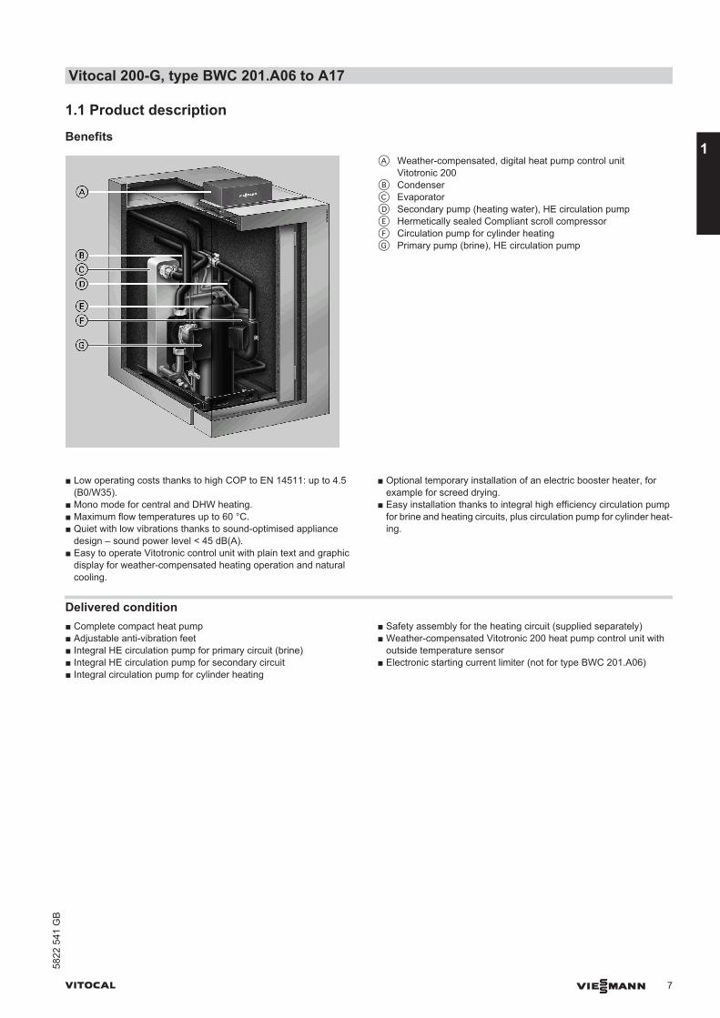
A Weather-compensated, digital heat pump control unitVitotronic 200
B CondenserC EvaporatorD Secondary pump (heating water), HE circulation pumpE Hermetically sealed Compliant scroll compressorF Circulation pump for cylinder heatingG Primary pump (brine), HE circulation pump
■ Low operating costs thanks to high COP to EN 14511: up to 4.5(B0/W35).
■ Mono mode for central and DHW heating.■ Maximum flow temperatures up to 60 °C.■ Quiet with low vibrations thanks to sound-optimised appliance
design – sound power level < 45 dB(A).■ Easy to operate Vitotronic control unit with plain text and graphic
display for weather-compensated heating operation and naturalcooling.
■ Optional temporary installation of an electric booster heater, forexample for screed drying.
■ Easy installation thanks to integral high efficiency circulation pumpfor brine and heating circuits, plus circulation pump for cylinder heat-ing.
Delivered condition■ Complete compact heat pump■ Adjustable anti-vibration feet■ Integral HE circulation pump for primary circuit (brine)■ Integral HE circulation pump for secondary circuit■ Integral circulation pump for cylinder heating
■ Safety assembly for the heating circuit (supplied separately)■ Weather-compensated Vitotronic 200 heat pump control unit with
outside temperature sensor■ Electronic starting current limiter (not for type BWC 201.A06)
Vitocal 200-G, type BWC 201.A06 to A17
VITOCAL VIESMANN 7
5822
541
GB
1
1.2 Specification
Specification
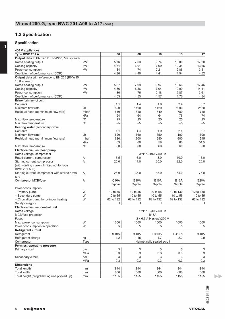
400 V appliancesType BWC 201.A 06 08 10 13 17Output data to EN 14511 (B0/W35, 5 K spread) Rated heating output kW 5.76 7.63 9.74 13.00 17.20Cooling capacity kW 4.51 6.01 7.69 10.34 13.66Power consumption kW 1.34 1.74 2.21 2.86 3.81Coefficient of performance ε (COP) 4.30 4.40 4.41 4.54 4.52Output data with reference to EN 255 (B0/W35,10 K spread)
Rated heating output kW 5.87 7.99 9.97 13.66 17.46Cooling capacity kW 4.66 6.36 7.94 10.99 14.11Power consumption kW 1.30 1.76 2.18 2.87 3.61Coefficient of performance ε (COP) 4.53 4.55 4.57 4.76 4.84Brine (primary circuit) Contents l 1.1 1.4 1.9 2.4 3.7Minimum flow rate l/h 820 1100 1420 1900 2520Residual head (at minimum flow rate) mbar 640 640 640 780 740 kPa 64 64 64 78 74Max. flow temperature °C 25 25 25 25 25Min. flow temperature °C –5 –5 –5 –5 –5Heating water (secondary circuit) Contents l 1.1 1.4 1.9 2.4 3.7Minimum flow rate l/h 520 660 850 1100 1500Residual head (at minimum flow rate) mbar 630 600 580 600 545 kPa 63 60 58 60 54.5Max. flow temperature °C 60 60 60 60 60Electrical values, heat pump Rated voltage, compressor 3/N/PE 400 V/50 HzRated current, compressor A 5.5 6.0 8.0 10.0 15.0Starting current, compressor(with starting current limiter, not for typeBWC 201.A06)
A 25.0 14.0 20.0 22.0 25.0
Starting current, compressor with stalled arma-ture
A 26.0 35.0 48.0 64.0 75.0
Compressor MCB/fuse A C16A3-pole
B16A3-pole
B16A3-pole
B16A3-pole
B20A3-pole
Power consumption: – Primary pump W 10 to 55 10 to 55 10 to 55 10 to 130 10 to 130– Secondary pump W 10 to 55 10 to 55 10 to 55 10 to 55 10 to 55– Circulation pump for cylinder heating W 62 to 132 62 to 132 62 to 132 62 to 132 62 to 132Safety category I I I I IElectrical values, control unit Rated voltage 1/N/PE 230 V/50 HzMCB/fuse protection B16AFuses 2 x 6.3 A H (slow)/250 VMax. power consumption W 1000 1000 1000 1000 1000Power consumption in operation W 5 5 5 5 5Refrigerant circuit Refrigerant R410A R410A R410A R410A R410ARefrigerant charge kg 1.2 1.45 1.7 2.2 2.9Compressor Type Hermetically sealed scrollPermiss. operating pressure Primary circuit bar 3 3 3 3 3 MPa 0.3 0.3 0.3 0.3 0.3Secondary circuit bar 3 3 3 3 3 MPa 0.3 0.3 0.3 0.3 0.3Dimensions Total length mm 844 844 844 844 844Total width mm 600 600 600 600 600Total height (programming unit pivoted up) mm 1155 1155 1155 1155 1155
Vitocal 200-G, type BWC 201.A06 to A17 (cont.)
8 VIESMANN VITOCAL
1
5822
541
GB
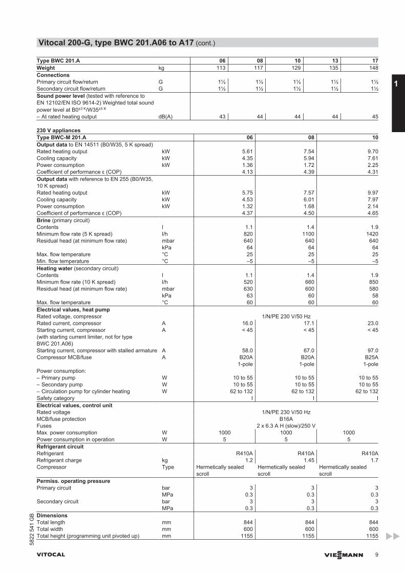
Type BWC 201.A 06 08 10 13 17Weight kg 113 117 129 135 148Connections Primary circuit flow/return G 1½ 1½ 1½ 1½ 1½Secondary circuit flow/return G 1½ 1½ 1½ 1½ 1½Sound power level (tested with reference toEN 12102/EN ISO 9614-2) Weighted total soundpower level at B0±3 K/W35±5 K
– At rated heating output dB(A) 43 44 44 44 45
230 V appliancesType BWC-M 201.A 06 08 10Output data to EN 14511 (B0/W35, 5 K spread) Rated heating output kW 5.61 7.54 9.70Cooling capacity kW 4.35 5.94 7.61Power consumption kW 1.36 1.72 2.25Coefficient of performance ε (COP) 4.13 4.39 4.31Output data with reference to EN 255 (B0/W35,10 K spread)
Rated heating output kW 5.75 7.57 9.97Cooling capacity kW 4.53 6.01 7.97Power consumption kW 1.32 1.68 2.14Coefficient of performance ε (COP) 4.37 4.50 4.65Brine (primary circuit) Contents l 1.1 1.4 1.9Minimum flow rate (5 K spread) l/h 820 1100 1420Residual head (at minimum flow rate) mbar 640 640 640 kPa 64 64 64Max. flow temperature °C 25 25 25Min. flow temperature °C –5 –5 –5Heating water (secondary circuit) Contents l 1.1 1.4 1.9Minimum flow rate (10 K spread) l/h 520 660 850Residual head (at minimum flow rate) mbar 630 600 580 kPa 63 60 58Max. flow temperature °C 60 60 60Electrical values, heat pump Rated voltage, compressor 1/N/PE 230 V/50 HzRated current, compressor A 16.0 17.1 23.0Starting current, compressor(with starting current limiter, not for typeBWC 201.A06)
A < 45 < 45 < 45
Starting current, compressor with stalled armature A 58.0 67.0 97.0Compressor MCB/fuse A B20A
1-poleB20A
1-poleB25A
1-polePower consumption: – Primary pump W 10 to 55 10 to 55 10 to 55– Secondary pump W 10 to 55 10 to 55 10 to 55– Circulation pump for cylinder heating W 62 to 132 62 to 132 62 to 132Safety category I I IElectrical values, control unit Rated voltage 1/N/PE 230 V/50 HzMCB/fuse protection B16AFuses 2 x 6.3 A H (slow)/250 VMax. power consumption W 1000 1000 1000Power consumption in operation W 5 5 5Refrigerant circuit Refrigerant R410A R410A R410ARefrigerant charge kg 1.2 1.45 1.7Compressor Type Hermetically sealed
scrollHermetically sealedscroll
Hermetically sealedscroll
Permiss. operating pressure Primary circuit bar 3 3 3 MPa 0.3 0.3 0.3Secondary circuit bar 3 3 3 MPa 0.3 0.3 0.3Dimensions Total length mm 844 844 844Total width mm 600 600 600Total height (programming unit pivoted up) mm 1155 1155 1155
Vitocal 200-G, type BWC 201.A06 to A17 (cont.)
VITOCAL VIESMANN 9
5822
541
GB
1
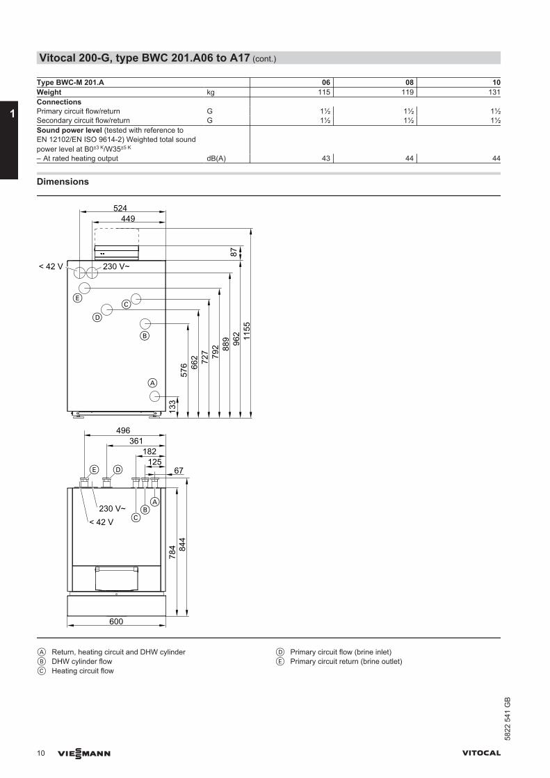
Type BWC-M 201.A 06 08 10Weight kg 115 119 131Connections Primary circuit flow/return G 1½ 1½ 1½Secondary circuit flow/return G 1½ 1½ 1½Sound power level (tested with reference toEN 12102/EN ISO 9614-2) Weighted total soundpower level at B0±3 K/W35±5 K
– At rated heating output dB(A) 43 44 44
Dimensions13
357
6 662 72
7 792 88
9 962 11
5587
67125
182361
496
449524
600
A
230 V~< 42 V
B
C
D
E
230 V~< 42 V
AB
C
E D
784 84
4
A Return, heating circuit and DHW cylinderB DHW cylinder flowC Heating circuit flow
D Primary circuit flow (brine inlet)E Primary circuit return (brine outlet)
Vitocal 200-G, type BWC 201.A06 to A17 (cont.)
10 VIESMANN VITOCAL
1
5822
541
GB
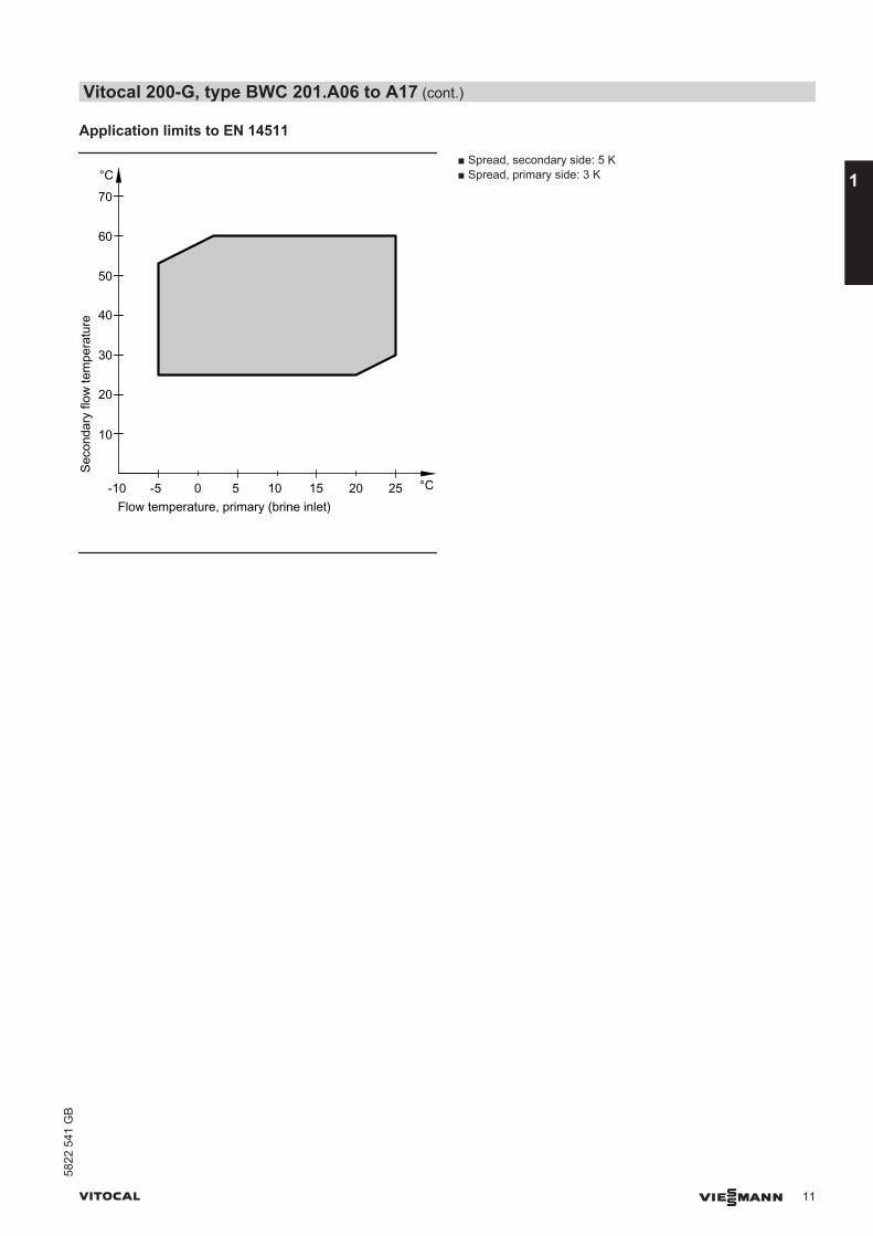
Application limits to EN 14511
Seco
ndar
y flo
w te
mpe
ratu
re
Flow temperature, primary (brine inlet)-5 0 5
°C
°C10 15 20 25-10
10
20
30
40
50
60
70
■ Spread, secondary side: 5 K■ Spread, primary side: 3 K
Vitocal 200-G, type BWC 201.A06 to A17 (cont.)
VITOCAL VIESMANN 11
5822
541
GB
1
Curves type BWC
Type BWC 201.A06
0
2
4
-10 -5 0 5 10 15 20 25
-10 -5 0 5 10 15 20 250
2
4
6
8
Water / brineinlet temperature in °C
0
2
4
6
8
10
-10 -5 0 5 10 15 20 25
0
2
4
6
8
10
-10 -5 0 5 10 15 20 25
35 °C45 °C55 °C60 °C
Coe
ffici
ent o
f per
f.C
OP
Ref
riger
atio
n ca
paci
ty in
kW
Pow
erco
nsum
ptio
n in
kW
Hea
ting
outp
ut in
kW
35 °C45 °C55 °C60 °C
35 °C45 °C55 °C60 °C
35 °C45 °C55 °C60 °C
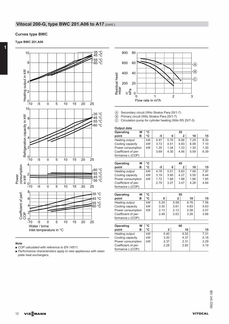
Note■ COP calculated with reference to EN 14511.■ Performance characteristics apply to new appliances with clean
plate heat exchangers.
200
0
600
400
800
0 1 2 3
Res
idua
l hea
d
Flow rate in m³/h
B
A
C20
0
60
40
80
kPa
mba
r
A Secondary circuit (Wilo Stratos Para 25/1-7)B Primary circuit (Wilo Stratos Para 25/1-7)C Circulation pump for cylinder heating (Wilo RS 25/7-3)
Output dataOperatingpoint
W °C 35B °C -5 0 2 10 15
Heating output kW 4.97 5.76 6.06 7.29 8.30Cooling capacity kW 3.72 4.51 4.83 6.08 7.10Power consumption kW 1.35 1.34 1.33 1.30 1.30Coefficient of per-formance ε (COP)
3.69 4.30 4.56 5.59 6.39
Operatingpoint
W °C 45B °C -5 0 2 10 15
Heating output kW 4.78 5.51 5.83 7.09 7.97Cooling capacity kW 3.19 3.95 4.27 5.55 6.44Power consumption kW 1.72 1.68 1.68 1.66 1.65Coefficient of per-formance ε (COP)
2.79 3.27 3.47 4.28 4.84
Operatingpoint
W °C 55B °C 0 2 10 15
Heating output kW 5.29 5.58 6.76 7.56Cooling capacity kW 3.30 3.61 4.83 5.63Power consumption kW 2.13 2.12 2.08 2.07Coefficient of per-formance ε (COP)
2.48 2.63 3.26 3.66
Operatingpoint
W °C 60B °C 2 10 15
Heating output kW 5.40 6.52 7.31Cooling capacity kW 3.20 4.37 5.18Power consumption kW 2.37 2.31 2.29Coefficient of per-formance ε (COP)
2.28 2.82 3.19
Vitocal 200-G, type BWC 201.A06 to A17 (cont.)
12 VIESMANN VITOCAL
1
5822
541
GB
Type BWC 201.A08
0
2
4
-10 -5 0 5 10 15 20 25
-10 -5 0 5 10 15 20 250
2
4
6
8
Water / brineinlet temperature in °C
0
2
4
6
8
10
-10 -5 0 5 10 15 20 25
12
14
0
2
4
6
8
10
-10 -5 0 5 10 15 20 25
12
14
35 °C
45 °C55 °C60 °C
Coe
ffici
ent o
f per
f.C
OP
Ref
riger
atio
n ca
paci
ty in
kW
Pow
erco
nsum
ptio
n in
kW
Hea
ting
outp
ut in
kW
35 °C45 °C
55 °C60 °C
35 °C45 °C55 °C60 °C
35 °C45 °C55 °C60 °C
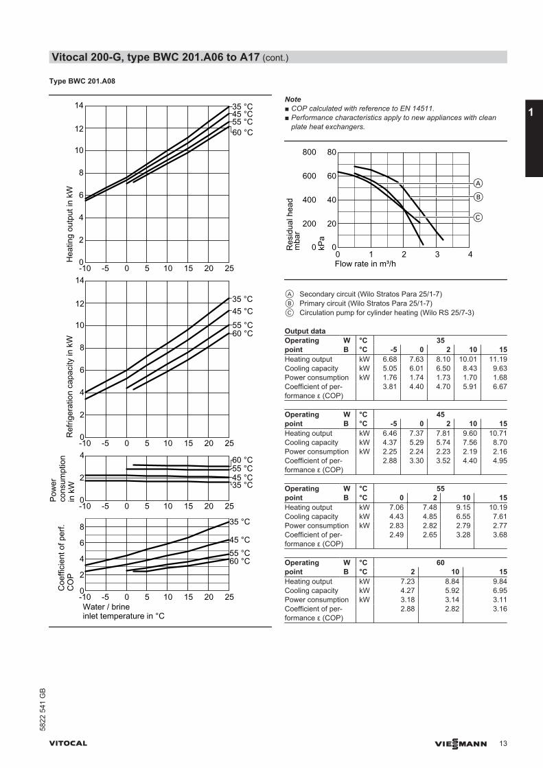
Note■ COP calculated with reference to EN 14511.■ Performance characteristics apply to new appliances with clean
plate heat exchangers.
200
0
600
400
800
0 1 2 3
Res
idua
l hea
d
Flow rate in m³/h
B
A
4
C
mba
r
kPa
20
0
60
40
80
A Secondary circuit (Wilo Stratos Para 25/1-7)B Primary circuit (Wilo Stratos Para 25/1-7)C Circulation pump for cylinder heating (Wilo RS 25/7-3)
Output dataOperatingpoint
W °C 35B °C -5 0 2 10 15
Heating output kW 6.68 7.63 8.10 10.01 11.19Cooling capacity kW 5.05 6.01 6.50 8.43 9.63Power consumption kW 1.76 1.74 1.73 1.70 1.68Coefficient of per-formance ε (COP)
3.81 4.40 4.70 5.91 6.67
Operatingpoint
W °C 45B °C -5 0 2 10 15
Heating output kW 6.46 7.37 7.81 9.60 10.71Cooling capacity kW 4.37 5.29 5.74 7.56 8.70Power consumption kW 2.25 2.24 2.23 2.19 2.16Coefficient of per-formance ε (COP)
2.88 3.30 3.52 4.40 4.95
Operatingpoint
W °C 55B °C 0 2 10 15
Heating output kW 7.06 7.48 9.15 10.19Cooling capacity kW 4.43 4.85 6.55 7.61Power consumption kW 2.83 2.82 2.79 2.77Coefficient of per-formance ε (COP)
2.49 2.65 3.28 3.68
Operatingpoint
W °C 60B °C 2 10 15
Heating output kW 7.23 8.84 9.84Cooling capacity kW 4.27 5.92 6.95Power consumption kW 3.18 3.14 3.11Coefficient of per-formance ε (COP)
2.88 2.82 3.16
Vitocal 200-G, type BWC 201.A06 to A17 (cont.)
VITOCAL VIESMANN 13
5822
541
GB
1
Type BWC 201.A10
0
2
4
-10 -5 0 5 10 15 20 25
-10 -5 0 5 10 15 20 250
2
4
6
8
Water / brineinlet temperature in °C
4
6
8
10
-10 -5 0 5 10 15 20 25
12
14
16
4
6
8
10
-10 -5 0 5 10 15 20 25
12
14
16
18
35 °C
45 °C55 °C60 °C
Coe
ffici
ent o
f per
f.C
OP
Ref
riger
atio
n ca
paci
ty in
kW
Pow
erco
nsum
ptio
n in
kW
Hea
ting
outp
ut in
kW
35 °C
45 °C
55 °C60 °C
35 °C45 °C55 °C60 °C
35 °C45 °C55 °C60 °C
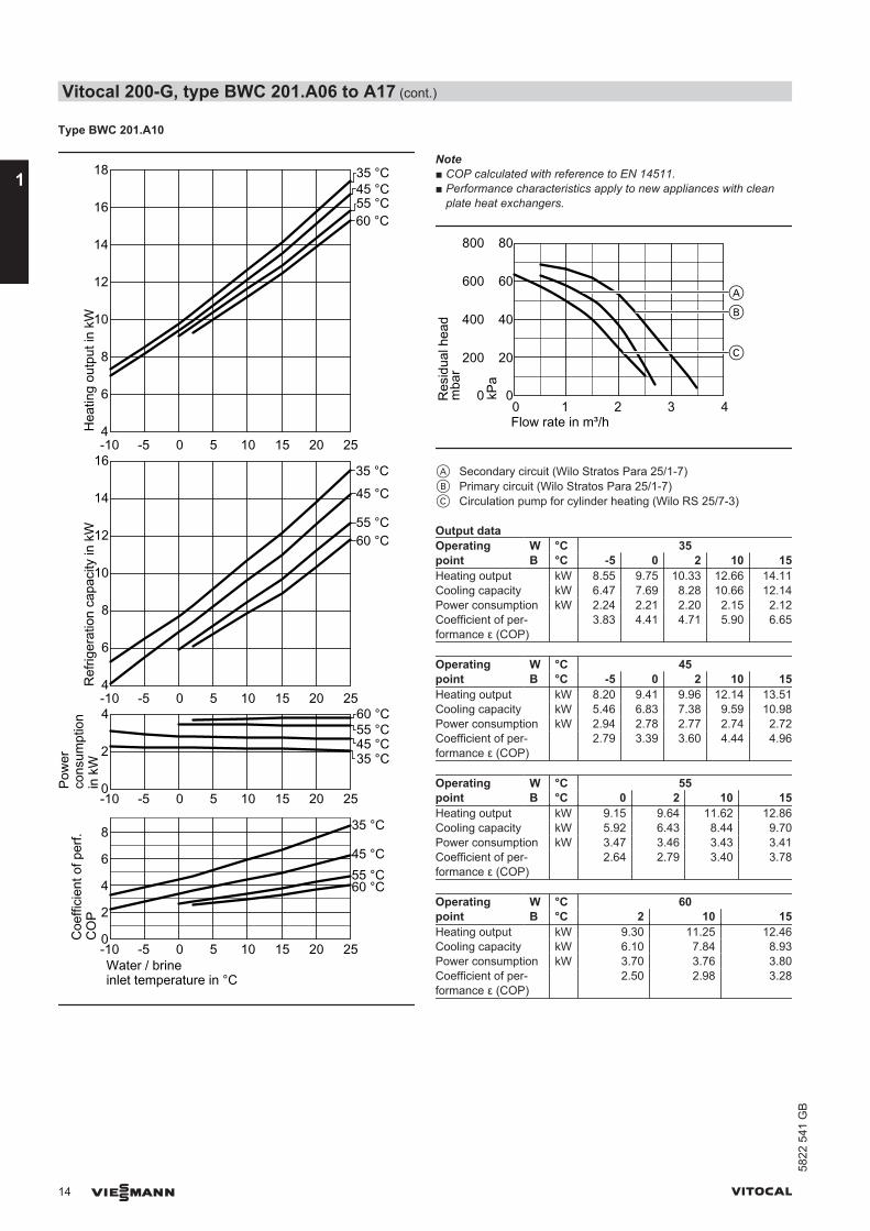
Note■ COP calculated with reference to EN 14511.■ Performance characteristics apply to new appliances with clean
plate heat exchangers.
200
0
600
400
800
0 1 2 3
Res
idua
l hea
dFlow rate in m³/h
B
4
A
C
mba
r
kPa
20
0
60
40
80
A Secondary circuit (Wilo Stratos Para 25/1-7)B Primary circuit (Wilo Stratos Para 25/1-7)C Circulation pump for cylinder heating (Wilo RS 25/7-3)
Output dataOperatingpoint
W °C 35B °C -5 0 2 10 15
Heating output kW 8.55 9.75 10.33 12.66 14.11Cooling capacity kW 6.47 7.69 8.28 10.66 12.14Power consumption kW 2.24 2.21 2.20 2.15 2.12Coefficient of per-formance ε (COP)
3.83 4.41 4.71 5.90 6.65
Operatingpoint
W °C 45B °C -5 0 2 10 15
Heating output kW 8.20 9.41 9.96 12.14 13.51Cooling capacity kW 5.46 6.83 7.38 9.59 10.98Power consumption kW 2.94 2.78 2.77 2.74 2.72Coefficient of per-formance ε (COP)
2.79 3.39 3.60 4.44 4.96
Operatingpoint
W °C 55B °C 0 2 10 15
Heating output kW 9.15 9.64 11.62 12.86Cooling capacity kW 5.92 6.43 8.44 9.70Power consumption kW 3.47 3.46 3.43 3.41Coefficient of per-formance ε (COP)
2.64 2.79 3.40 3.78
Operatingpoint
W °C 60B °C 2 10 15
Heating output kW 9.30 11.25 12.46Cooling capacity kW 6.10 7.84 8.93Power consumption kW 3.70 3.76 3.80Coefficient of per-formance ε (COP)
2.50 2.98 3.28
Vitocal 200-G, type BWC 201.A06 to A17 (cont.)
14 VIESMANN VITOCAL
1
5822
541
GB
Type BWC 201.A13
0
5
-10 -5 0 5 10 15 20 25
-10 -5 0 5 10 15 20 250
2
4
6
8
Water / brineinlet temperature in °C
10
0
5
25
-10 -5 0 5 10 15 20 25
20
15
10
0
5
25
-10 -5 0 5 10 15 20 25
20
15
10
35 °C45 °C55 °C60 °C
Coe
ffici
ent o
f per
f.C
OP
Ref
riger
atio
n ca
paci
ty in
kW
Pow
erco
nsum
ptio
n in
kW
Hea
ting
outp
ut in
kW
35 °C45 °C55 °C60 °C
35 °C45 °C55 °C60 °C
35 °C45 °C55 °C60 °C
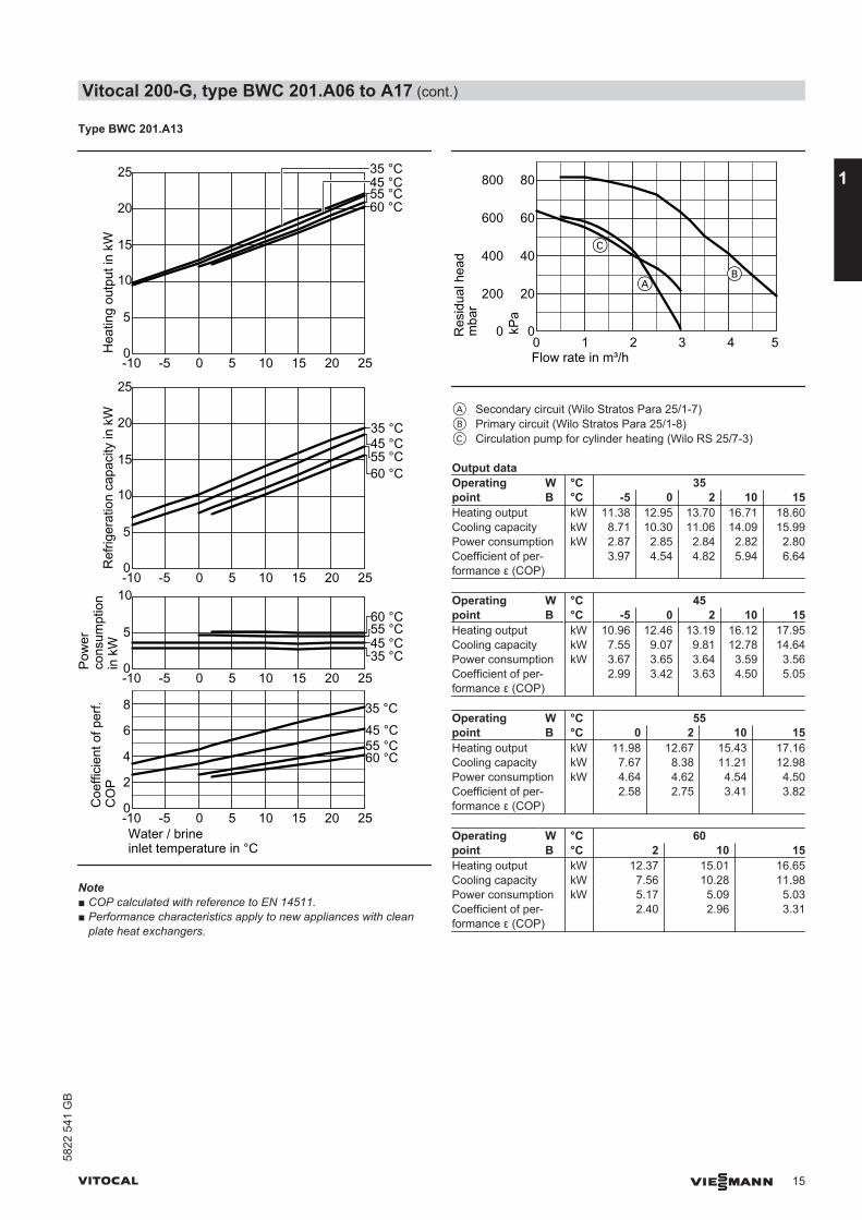
Note■ COP calculated with reference to EN 14511.■ Performance characteristics apply to new appliances with clean
plate heat exchangers.
200
0
600
400
800
0 1 2 3
Res
idua
l hea
d
Flow rate in m³/h
A
4 5
B
mba
r
kPa
20
0
60
40
80
C
A Secondary circuit (Wilo Stratos Para 25/1-7)B Primary circuit (Wilo Stratos Para 25/1-8)C Circulation pump for cylinder heating (Wilo RS 25/7-3)
Output dataOperatingpoint
W °C 35B °C -5 0 2 10 15
Heating output kW 11.38 12.95 13.70 16.71 18.60Cooling capacity kW 8.71 10.30 11.06 14.09 15.99Power consumption kW 2.87 2.85 2.84 2.82 2.80Coefficient of per-formance ε (COP)
3.97 4.54 4.82 5.94 6.64
Operatingpoint
W °C 45B °C -5 0 2 10 15
Heating output kW 10.96 12.46 13.19 16.12 17.95Cooling capacity kW 7.55 9.07 9.81 12.78 14.64Power consumption kW 3.67 3.65 3.64 3.59 3.56Coefficient of per-formance ε (COP)
2.99 3.42 3.63 4.50 5.05
Operatingpoint
W °C 55B °C 0 2 10 15
Heating output kW 11.98 12.67 15.43 17.16Cooling capacity kW 7.67 8.38 11.21 12.98Power consumption kW 4.64 4.62 4.54 4.50Coefficient of per-formance ε (COP)
2.58 2.75 3.41 3.82
Operatingpoint
W °C 60B °C 2 10 15
Heating output kW 12.37 15.01 16.65Cooling capacity kW 7.56 10.28 11.98Power consumption kW 5.17 5.09 5.03Coefficient of per-formance ε (COP)
2.40 2.96 3.31
Vitocal 200-G, type BWC 201.A06 to A17 (cont.)
VITOCAL VIESMANN 15
5822
541
GB
1
Type BWC 201.A17
0
5
10
-10 -5 0 5 10 15 20 25
-10 -5 0 5 10 15 20 250
2
4
6
8
Water / brineinlet temperature in °C
35 °C
45 °C55 °C60 °C
Coe
ffici
ent o
f per
f.C
OP
Ref
riger
atio
n ca
paci
ty in
kW
Pow
erco
nsum
ptio
n in
kW
Hea
ting
outp
ut in
kW
35 °C45 °C55 °C60 °C
5
10
15
20
25
30
-10 -5 0 5 10 15 20 25
5
10
15
20
25
30
35
-10 -5 0 5 10 15 20 25
35 °C45 °C55 °C60 °C
35 °C45 °C55 °C60 °C
Note■ COP calculated with reference to EN 14511.■ Performance characteristics apply to new appliances with clean
plate heat exchangers.
200
0
600
400
800
0 1 2 3 4 5 6 7
Res
idua
l hea
d
Flow rate in m³/h
mba
r
kPa
20
0
60
40
80
A
B
C
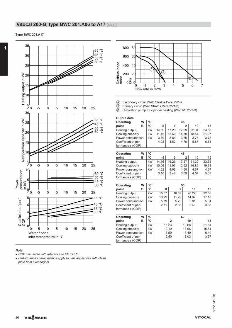
A Secondary circuit (Wilo Stratos Para 25/1-7)B Primary circuit (Wilo Stratos Para 25/1-8)C Circulation pump for cylinder heating (Wilo RS 25/7-3)
Output dataOperatingpoint
W °C 35B °C -5 0 2 10 15
Heating output kW 14.89 17.20 17.99 22.04 24.56Cooling capacity kW 11.45 13.66 14.50 18.54 21.07Power consumption kW 3.70 3.81 3.76 3.76 3.75Coefficient of per-formance ε (COP)
4.02 4.52 4.79 5.87 6.55
Operatingpoint
W °C 45B °C -5 0 2 10 15
Heating output kW 14.36 16.29 17.27 21.20 23.65Cooling capacity kW 10.06 11.93 12.92 16.85 19.31Power consumption kW 4.62 4.68 4.68 4.67 4.67Coefficient of per-formance ε (COP)
3.10 3.48 3.69 4.54 5.07
Operatingpoint
W °C 55B °C 0 2 10 15
Heating output kW 15.67 16.59 20.27 22.56Cooling capacity kW 10.29 11.20 14.87 17.16Power consumption kW 5.79 5.79 5.81 5.81Coefficient of per-formance ε (COP)
2.71 2.86 3.49 3.88
Operatingpoint
W °C 60B °C 2 10 15
Heating output kW 16.23 19.68 21.84Cooling capacity kW 10.19 13.65 15.81Power consumption kW 6.50 6.49 6.49Coefficient of per-formance ε (COP)
2.50 3.03 3.37
Vitocal 200-G, type BWC 201.A06 to A17 (cont.)
16 VIESMANN VITOCAL
1
5822
541
GB

Curves type BWC-M
Type BWC-M 201.A06
0
2
-10 -5 0 5 10 15 20 25
-10 -5 0 5 10 15 20 250
2
4
6
8
Water / brineinlet temperature in °C
4
35 °C45 °C55 °C60 °C
Coe
ffici
ent o
f per
f.C
OP
Ref
riger
atio
n ca
paci
ty in
kW
Pow
erco
nsum
ptio
n in
kW
Hea
ting
outp
ut in
kW
35 °C45 °C55 °C60 °C
0
2
-10 -5 0 5 10 15 20 25
4
6
8
10
0
2
-10 -5 0 5 10 15 20 25
4
6
8
10
35 °C45 °C55 °C60 °C
35 °C 45 °C55 °C60 °C
Note■ COP calculated with reference to EN 14511.■ Performance characteristics apply to new appliances with clean
plate heat exchangers.
200
0
600
400
800
0 1 2 3
Res
idua
l hea
d
Flow rate in m³/h
B
A
C20
0
60
40
80
kPa
mba
r
A Secondary circuit (Wilo Stratos Para 25/1-7)B Primary circuit (Wilo Stratos Para 25/1-7)C Circulation pump for cylinder heating (Wilo RS 25/7-3)
Output dataOperatingpoint
W °C 35B °C -5 0 2 10 15
Heating output kW 4.84 5.56 5.91 7.32 8.09Cooling capacity kW 3.58 4.31 4.66 6.09 6.86Power consumption kW 1.35 1.34 1.34 1.33 1.32Coefficient of per-formance ε (COP)
3.58 4.14 4.41 5.51 6.12
Operatingpoint
W °C 45B °C -5 0 2 10 15
Heating output kW 4.61 5.29 5.62 6.97 7.81Cooling capacity kW 3.04 3.72 4.07 5.44 6.30Power consumption kW 1.70 1.68 1.67 1.64 1.62Coefficient of per-formance ε (COP)
2.72 3.14 3.37 4.25 4.81
Operatingpoint
W °C 55B °C 0 2 10 15
Heating output kW 5.00 5.31 6.53 7.29Cooling capacity kW 2.97 3.29 4.54 5.33Power consumption kW 2.18 2.17 2.14 2.11Coefficient of per-formance ε (COP)
2.29 2.45 3.07 3.46
Operatingpoint
W °C 60B °C 2 10 15
Heating output kW 5.10 6.26 7.03Cooling capacity kW 2.90 4.01 4.83Power consumption kW 2.40 2.41 2.36Coefficient of per-formance ε (COP)
2.13 2.61 2.98
Vitocal 200-G, type BWC 201.A06 to A17 (cont.)
VITOCAL VIESMANN 17
5822
541
GB
1
Type BWC-M 201.A08
0
2
-10 -5 0 5 10 15 20 25
-10 -5 0 5 10 15 20 250
2
4
6
8
Water / brineinlet temperature in °C
4
2-10 -5 0 5 10 15 20 25
4
6
8
10
12
14
2-10 -5 0 5 10 15 20 25
4
6
8
10
12
14
Coe
ffici
ent o
f per
f.C
OP
Ref
riger
atio
n ca
paci
ty in
kW
Pow
erco
nsum
ptio
n in
kW
Hea
ting
outp
ut in
kW
35 °C
45 °C55 °C60 °C
35 °C45 °C
55 °C60 °C
35 °C45 °C55 °C60 °C
35 °C45 °C
55 °C60 °C
Note■ COP calculated with reference to EN 14511.■ Performance characteristics apply to new appliances with clean
plate heat exchangers.
200
0
600
400
800
0 1 2 3
Res
idua
l hea
d
Flow rate in m³/h
B
A
4
C
mba
r
kPa
20
0
60
40
80
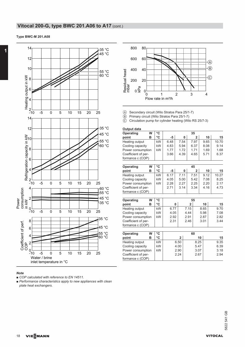
A Secondary circuit (Wilo Stratos Para 25/1-7)B Primary circuit (Wilo Stratos Para 25/1-7)C Circulation pump for cylinder heating (Wilo RS 25/7-3)
Output dataOperatingpoint
W °C 35B °C -5 0 2 10 15
Heating output kW 6.48 7.54 7.97 9.65 10.70Cooling capacity kW 4.83 5.94 6.37 8.08 9.14Power consumption kW 1.77 1.72 1.71 1.69 1.68Coefficient of per-formance ε (COP)
3.66 4.39 4.65 5.71 6.37
Operatingpoint
W °C 45B °C -5 0 2 10 15
Heating output kW 6.17 7.11 7.51 9.12 10.27Cooling capacity kW 4.05 5.00 5.42 7.08 8.25Power consumption kW 2.28 2.27 2.25 2.20 2.17Coefficient of per-formance ε (COP)
2.71 3.14 3.34 4.16 4.73
Operatingpoint
W °C 55B °C 0 2 10 15
Heating output kW 6.77 7.15 8.65 9.70Cooling capacity kW 4.05 4.44 5.98 7.08Power consumption kW 2.92 2.91 2.87 2.82Coefficient of per-formance ε (COP)
2.31 2.46 3.01 3.44
Operatingpoint
W °C 60B °C 2 10 15
Heating output kW 6.50 8.25 9.35Cooling capacity kW 4.00 5.47 6.39Power consumption kW 2.90 3.07 3.18Coefficient of per-formance ε (COP)
2.24 2.67 2.94
Vitocal 200-G, type BWC 201.A06 to A17 (cont.)
18 VIESMANN VITOCAL
1
5822
541
GB

Type BWC-M 201.A10
-10 -5 0 5 10 15 20 25
-10 -5 0 5 10 15 20 250
2
4
6
8
Water / brineinlet temperature in °C
4
6
8
10
12
14
16
Coe
ffici
ent o
f per
f.C
OP
Ref
riger
atio
n ca
paci
ty in
kW
Pow
erco
nsum
ptio
n in
kW
Hea
ting
outp
ut in
kW
35 °C
45 °C55 °C60 °C
0
2
-10 -5 0 5 10 15 20 25
4
6
-10 -5 0 5 10 15 20 254
6
8
10
12
14
16
18
35 °C
45 °C
55 °C60 °C
35 °C45 °C55 °C60 °C
35 °C45 °C55 °C60 °C
Note■ COP calculated with reference to EN 14511.■ Performance characteristics apply to new appliances with clean
plate heat exchangers.
200
0
600
400
800
0 1 2 3
Res
idua
l hea
d
Flow rate in m³/h
B
4
A
C
mba
r
kPa
20
0
60
40
80
A Secondary circuit (Wilo Stratos Para 25/1-7)B Primary circuit (Wilo Stratos Para 25/1-7)C Circulation pump for cylinder heating (Wilo RS 25/7-3)
Output dataOperatingpoint
W °C 35B °C -5 0 2 10 15
Heating output kW 8.53 9.70 10.32 12.80 14.07Cooling capacity kW 6.41 7.61 8.23 10.71 12.10Power consumption kW 2.28 2.25 2.25 2.25 2.12Coefficient of per-formance ε (COP)
3.75 4.31 4.59 5.69 6.64
Operatingpoint
W °C 45B °C -5 0 2 10 15
Heating output kW 8.20 9.24 9.80 12.04 13.44Cooling capacity kW 5.53 6.55 7.13 9.45 10.89Power consumption kW 2.87 2.90 2.88 2.79 2.74Coefficient of per-formance ε (COP)
2.86 3.19 3.42 4.33 4.90
Operatingpoint
W °C 55B °C 0 2 10 15
Heating output kW 8.99 9.51 11.58 12.87Cooling capacity kW 5.51 6.05 8.23 9.60Power consumption kW 3.75 3.72 3.60 3.52Coefficient of per-formance ε (COP)
2.40 2.57 3.24 3.66
Operatingpoint
W °C 60B °C 2 10 15
Heating output kW 9.00 11.16 12.51Cooling capacity kW 5.00 7.34 8.80Power consumption kW 4.00 4.00 3.99Coefficient of per-formance ε (COP)
2.25 2.79 3.13
Vitocal 200-G, type BWC 201.A06 to A17 (cont.)
VITOCAL VIESMANN 19
5822
541
GB
1
2.1 Product description
Benefits of type BW, BWS
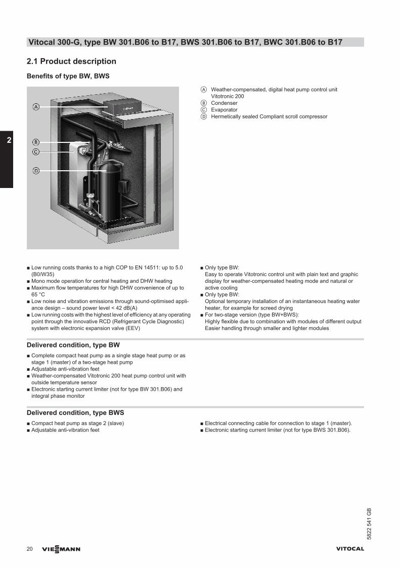
A Weather-compensated, digital heat pump control unitVitotronic 200
B CondenserC EvaporatorD Hermetically sealed Compliant scroll compressor
■ Low running costs thanks to a high COP to EN 14511: up to 5.0(B0/W35)
■ Mono mode operation for central heating and DHW heating■ Maximum flow temperatures for high DHW convenience of up to
65 °C■ Low noise and vibration emissions through sound-optimised appli-
ance design – sound power level < 42 dB(A)■ Low running costs with the highest level of efficiency at any operating
point through the innovative RCD (Refrigerant Cycle Diagnostic)system with electronic expansion valve (EEV)
■ Only type BW:Easy to operate Vitotronic control unit with plain text and graphicdisplay for weather-compensated heating mode and natural oractive cooling
■ Only type BW:Optional temporary installation of an instantaneous heating waterheater, for example for screed drying
■ For two-stage version (type BW+BWS):Highly flexible due to combination with modules of different outputEasier handling through smaller and lighter modules
Delivered condition, type BW■ Complete compact heat pump as a single stage heat pump or as
stage 1 (master) of a two-stage heat pump■ Adjustable anti-vibration feet■ Weather-compensated Vitotronic 200 heat pump control unit with
outside temperature sensor■ Electronic starting current limiter (not for type BW 301.B06) and
integral phase monitor
Delivered condition, type BWS■ Compact heat pump as stage 2 (slave)■ Adjustable anti-vibration feet
■ Electrical connecting cable for connection to stage 1 (master).■ Electronic starting current limiter (not for type BWS 301.B06).
Vitocal 300-G, type BW 301.B06 to B17, BWS 301.B06 to B17, BWC 301.B06 to B17
20 VIESMANN VITOCAL
2
5822
541
GB

Benefits of type BWC
A Weather-compensated, digital heat pump control unitVitotronic 200
B CondenserC EvaporatorD Secondary pump (heating water), HE circulation pumpE Hermetically sealed Compliant scroll compressorF Circulation pump for cylinder heatingG Primary pump (brine), HE circulation pump
■ Low running costs thanks to a high COP to EN 14511: up to 5.0(B0/W35)
■ Mono mode operation for central heating and DHW heating■ Maximum flow temperatures for high DHW convenience of up to
65 °C■ Low noise and vibration emissions through sound-optimised appli-
ance design – sound power level < 42 dB(A)■ Low running costs with the highest level of efficiency at any operating
point through the innovative RCD (Refrigerant Cycle Diagnostic)system with electronic expansion valve (EEV)
■ Easy to operate Vitotronic control unit with plain text and graphicdisplay for weather-compensated heating mode and natural oractive cooling
■ Optional temporary installation of an instantaneous heating waterheater, for example for screed drying
Delivered condition, type BWC■ Complete compact heat pump■ Adjustable anti-vibration feet■ Integral HE brine circuit pump (primary circuit)■ Integral HE circulation pump for secondary circuit■ Integral circulation pump for cylinder heating
■ Safety assembly for the heating circuit (supplied separately)■ Weather-compensated Vitotronic 200 heat pump control unit with
outside temperature sensor■ Electronic starting current limiter (not for type BWC 301.B06) and
integral phase monitor
Vitocal 300-G, type BW 301.B06 to B17, BWS 301.B06 to B17, BWC 301.B06 to B17 (cont.)
VITOCAL VIESMANN 21
5822
541
GB
2
2.2 Specification
Specification for brine/water heat pumps
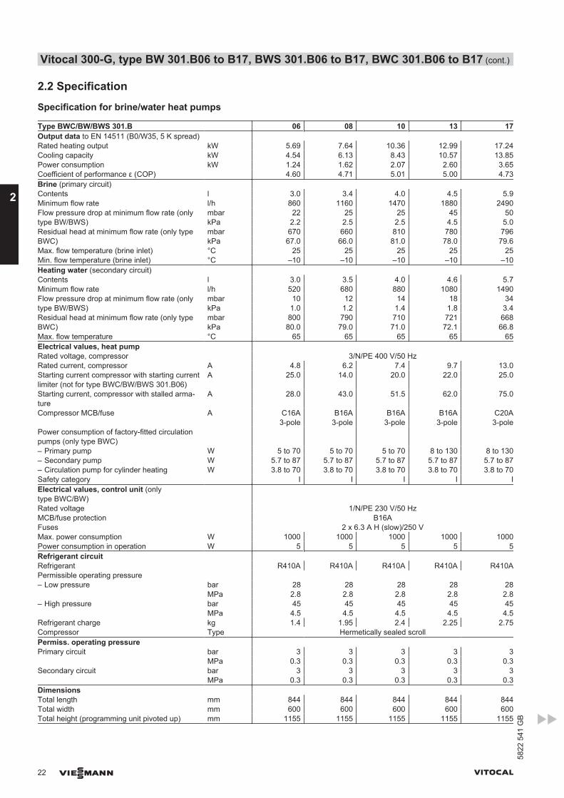
Type BWC/BW/BWS 301.B 06 08 10 13 17Output data to EN 14511 (B0/W35, 5 K spread) Rated heating output kW 5.69 7.64 10.36 12.99 17.24Cooling capacity kW 4.54 6.13 8.43 10.57 13.85Power consumption kW 1.24 1.62 2.07 2.60 3.65Coefficient of performance ε (COP) 4.60 4.71 5.01 5.00 4.73Brine (primary circuit) Contents l 3.0 3.4 4.0 4.5 5.9Minimum flow rate l/h 860 1160 1470 1880 2490Flow pressure drop at minimum flow rate (onlytype BW/BWS)
mbar 22 25 25 45 50kPa 2.2 2.5 2.5 4.5 5.0
Residual head at minimum flow rate (only typeBWC)
mbar 670 660 810 780 796kPa 67.0 66.0 81.0 78.0 79.6
Max. flow temperature (brine inlet) °C 25 25 25 25 25Min. flow temperature (brine inlet) °C –10 –10 –10 –10 –10Heating water (secondary circuit) Contents l 3.0 3.5 4.0 4.6 5.7Minimum flow rate l/h 520 680 880 1080 1490Flow pressure drop at minimum flow rate (onlytype BW/BWS)
mbar 10 12 14 18 34kPa 1.0 1.2 1.4 1.8 3.4
Residual head at minimum flow rate (only typeBWC)
mbar 800 790 710 721 668kPa 80.0 79.0 71.0 72.1 66.8
Max. flow temperature °C 65 65 65 65 65Electrical values, heat pump Rated voltage, compressor 3/N/PE 400 V/50 HzRated current, compressor A 4.8 6.2 7.4 9.7 13.0Starting current compressor with starting currentlimiter (not for type BWC/BW/BWS 301.B06)
A 25.0 14.0 20.0 22.0 25.0
Starting current, compressor with stalled arma-ture
A 28.0 43.0 51.5 62.0 75.0
Compressor MCB/fuse A C16A3-pole
B16A3-pole
B16A3-pole
B16A3-pole
C20A3-pole
Power consumption of factory-fitted circulationpumps (only type BWC)
– Primary pump W 5 to 70 5 to 70 5 to 70 8 to 130 8 to 130– Secondary pump W 5.7 to 87 5.7 to 87 5.7 to 87 5.7 to 87 5.7 to 87– Circulation pump for cylinder heating W 3.8 to 70 3.8 to 70 3.8 to 70 3.8 to 70 3.8 to 70Safety category I I I I IElectrical values, control unit (onlytype BWC/BW)
Rated voltage 1/N/PE 230 V/50 HzMCB/fuse protection B16AFuses 2 x 6.3 A H (slow)/250 VMax. power consumption W 1000 1000 1000 1000 1000Power consumption in operation W 5 5 5 5 5Refrigerant circuit Refrigerant R410A R410A R410A R410A R410APermissible operating pressure – Low pressure bar 28 28 28 28 28 MPa 2.8 2.8 2.8 2.8 2.8– High pressure bar 45 45 45 45 45 MPa 4.5 4.5 4.5 4.5 4.5Refrigerant charge kg 1.4 1.95 2.4 2.25 2.75Compressor Type Hermetically sealed scrollPermiss. operating pressure Primary circuit bar 3 3 3 3 3 MPa 0.3 0.3 0.3 0.3 0.3Secondary circuit bar 3 3 3 3 3 MPa 0.3 0.3 0.3 0.3 0.3Dimensions Total length mm 844 844 844 844 844Total width mm 600 600 600 600 600Total height (programming unit pivoted up) mm 1155 1155 1155 1155 1155
Vitocal 300-G, type BW 301.B06 to B17, BWS 301.B06 to B17, BWC 301.B06 to B17 (cont.)
22 VIESMANN VITOCAL
2
5822
541
GB
Type BWC/BW/BWS 301.B 06 08 10 13 17Weight Heat pump, type BWC kg 123 127 139 145 158Heat pump stage 1, type BW 301.B kg 113 117 129 135 148Heat pump stage 2, type BWS 301.B kg 109 113 125 131 144Connections Primary circuit flow/return G 1½ 1½ 1½ 1½ 1½Secondary circuit flow/return G 1½ 1½ 1½ 1½ 1½Sound power level (tested with reference toEN 12102/EN ISO 9614-2) Weighted total soundpower level at B0±3 K/W35±5 K
– At rated heating output dB(A) 40 41 41 41 42
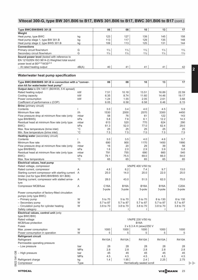
Water/water heat pump specification
Type BWC/BW/BWS 301.B in connection with a "conver-sion kit for water/water heat pump"
06 08 10 13 17
Output data to EN 14511 (B0/W35, 5 K spread) Rated heating output kW 7.51 10.18 13.51 16.89 22.59Cooling capacity kW 6.35 8.74 11.60 14.46 19.17Power consumption kW 1.24 1.55 2.05 2.61 3.68Coefficient of performance ε (COP) 6.05 6.58 6.58 6.46 6.15Brine (primary circuit) Contents l 3.0 3.4 4.0 4.5 5.9Minimum flow rate l/h 1530 2000 2570 3300 4450Flow pressure drop at minimum flow rate (onlytype BW/BWS)
mbar 58 76 61 122 143kPa 5.8 7.6 6.1 12.2 14.3
Residual head at minimum flow rate (only typeBWC)
mbar 613 520 770 624 290kPa 61.3 52.0 77.0 62.4 29.0
Max. flow temperature (brine inlet) °C 25 25 25 25 25Min. flow temperature (brine inlet) °C 7.5 7.5 7.5 7.5 7.5Heating water (secondary circuit) Contents l 3.0 3.5 4.0 4.6 5.7Minimum flow rate l/h 690 900 1170 1450 1990Flow pressure drop at minimum flow rate (onlytype BW/BWS)
mbar 16 20 29 39 58kPa 1.6 2.0 2.9 3.9 5.8
Residual head at minimum flow rate (only typeBWC)
mbar 791 755 690 660 540kPa 79.1 75.5 69.0 66.0 54.0
Max. flow temperature °C 65 65 65 65 65Electrical values, heat pump Rated voltage, compressor 3/N/PE 400 V/50 HzRated current, compressor A 4.8 6.2 7.4 9.7 13.0Starting current compressor with starting currentlimiter (not for type BWC/BW/BWS 301.B06)
A 25.0 14.0 20.0 22.0 25.0
Starting current, compressor with stalled arma-ture
A 28.0 43.0 51.5 62.0 75.0
Compressor MCB/fuse A C16A3-pole
B16A3-pole
B16A3-pole
B16A3-pole
C20A3-pole
Power consumption of factory-fitted circulationpumps (only type BWC)
– Primary pump W 5 to 70 5 to 70 5 to 70 8 to 130 8 to 130– Secondary pump W 5.7 to 87 5.7 to 87 5.7 to 87 5.7 to 87 5.7 to 87– Circulation pump for cylinder heating W 3.8 to 70 3.8 to 70 3.8 to 70 3.8 to 70 3.8 to 70Safety category I I I I IElectrical values, control unit (onlytype BWC/BW)
Rated voltage 1/N/PE 230 V/50 HzMCB/fuse protection B16AFuses 2 x 6.3 A H (slow)/250 VMax. power consumption W 1000 1000 1000 1000 1000Power consumption in operation W 5 5 5 5 5Refrigerant circuit Refrigerant R410A R410A R410A R410A R410APermissible operating pressure – Low pressure bar 28 28 28 28 28 MPa 2.8 2.8 2.8 2.8 2.8– High pressure bar 45 45 45 45 45 MPa 4.5 4.5 4.5 4.5 4.5Refrigerant charge kg 1.4 1.95 2.4 2.25 2.75Compressor Type Hermetically sealed scroll
Vitocal 300-G, type BW 301.B06 to B17, BWS 301.B06 to B17, BWC 301.B06 to B17 (cont.)
VITOCAL VIESMANN 23
5822
541
GB
2
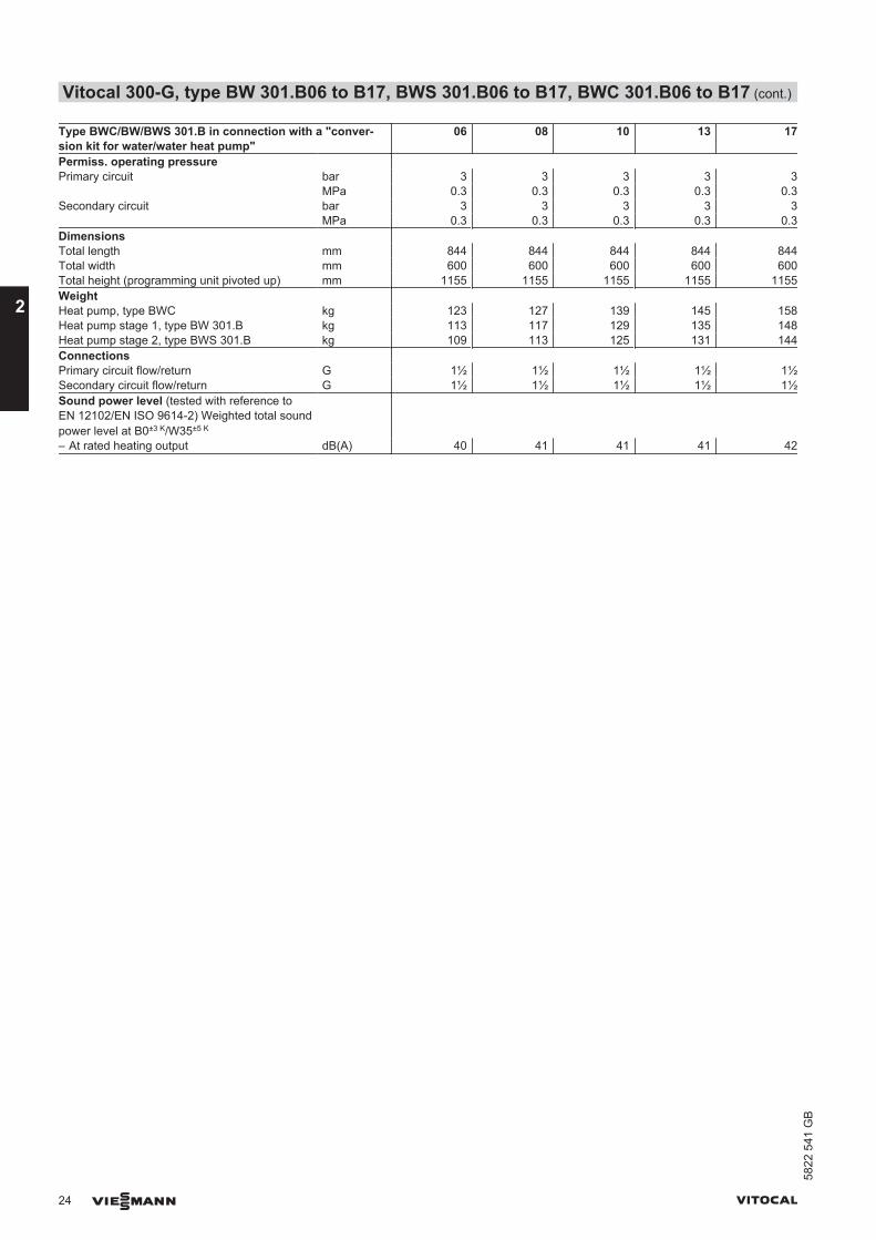
Type BWC/BW/BWS 301.B in connection with a "conver-sion kit for water/water heat pump"
06 08 10 13 17
Permiss. operating pressure Primary circuit bar 3 3 3 3 3 MPa 0.3 0.3 0.3 0.3 0.3Secondary circuit bar 3 3 3 3 3 MPa 0.3 0.3 0.3 0.3 0.3Dimensions Total length mm 844 844 844 844 844Total width mm 600 600 600 600 600Total height (programming unit pivoted up) mm 1155 1155 1155 1155 1155Weight Heat pump, type BWC kg 123 127 139 145 158Heat pump stage 1, type BW 301.B kg 113 117 129 135 148Heat pump stage 2, type BWS 301.B kg 109 113 125 131 144Connections Primary circuit flow/return G 1½ 1½ 1½ 1½ 1½Secondary circuit flow/return G 1½ 1½ 1½ 1½ 1½Sound power level (tested with reference toEN 12102/EN ISO 9614-2) Weighted total soundpower level at B0±3 K/W35±5 K
– At rated heating output dB(A) 40 41 41 41 42
Vitocal 300-G, type BW 301.B06 to B17, BWS 301.B06 to B17, BWC 301.B06 to B17 (cont.)
24 VIESMANN VITOCAL
2
5822
541
GB
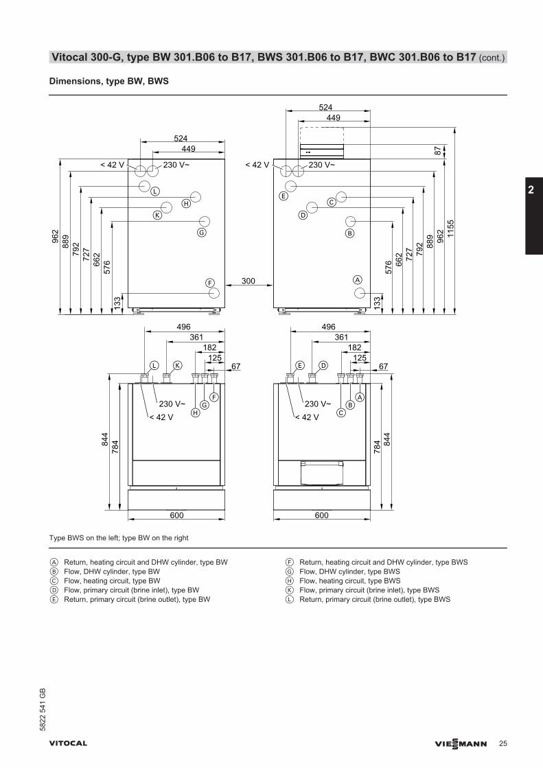
Dimensions, type BW, BWS
133
57666
272779
288996
2
133
576 66
2 727 79
2 889 96
2 1155
87
67125
182361
496
67125
182361
496
449524
449524
600 600
300
230 V~< 42 V
A
78484
4
230 V~< 42 V
B
C
D
E
F
G
H
K
L
230 V~< 42 V
230 V~< 42 V
AB
C
E D
FG
H
L K78
4 844
Type BWS on the left; type BW on the right
A Return, heating circuit and DHW cylinder, type BWB Flow, DHW cylinder, type BWC Flow, heating circuit, type BWD Flow, primary circuit (brine inlet), type BWE Return, primary circuit (brine outlet), type BW
F Return, heating circuit and DHW cylinder, type BWSG Flow, DHW cylinder, type BWSH Flow, heating circuit, type BWSK Flow, primary circuit (brine inlet), type BWSL Return, primary circuit (brine outlet), type BWS
Vitocal 300-G, type BW 301.B06 to B17, BWS 301.B06 to B17, BWC 301.B06 to B17 (cont.)
VITOCAL VIESMANN 25
5822
541
GB
2
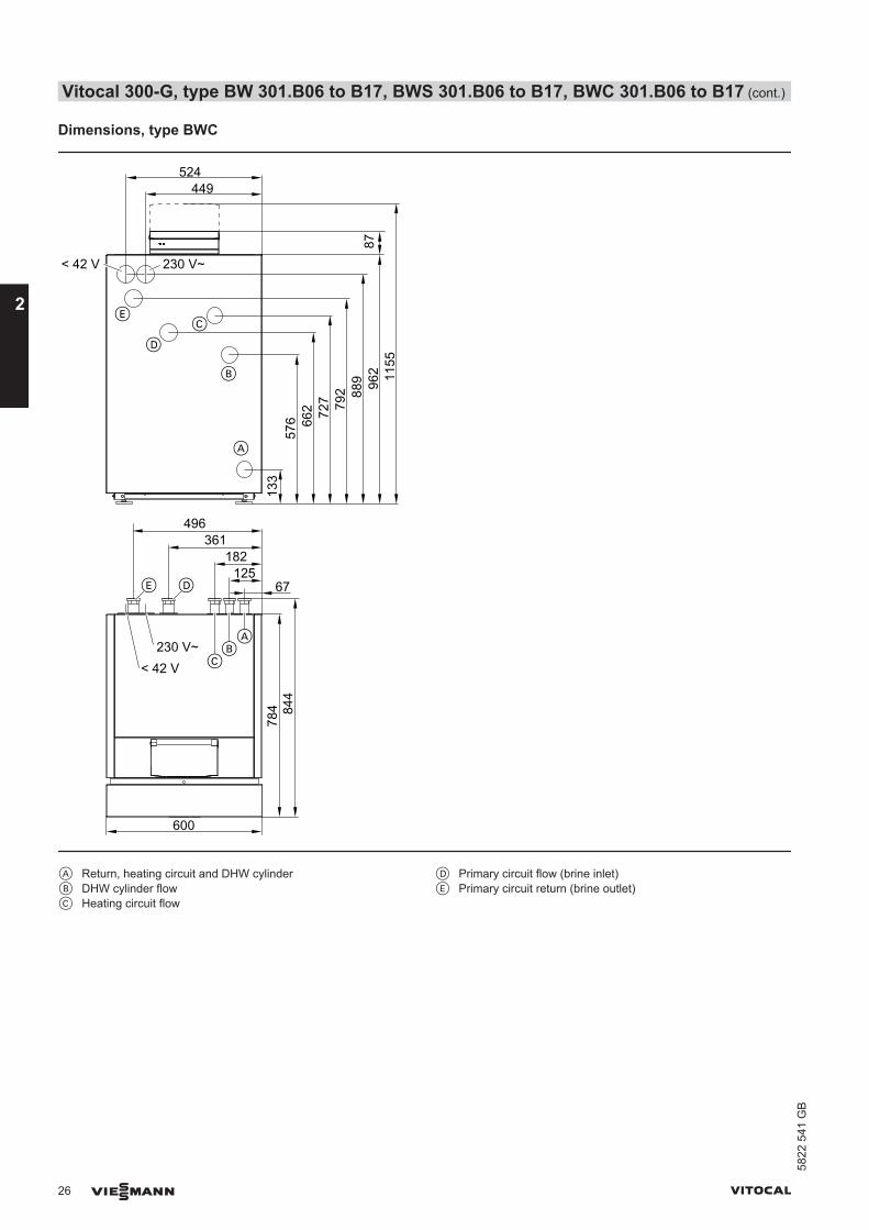
Dimensions, type BWC
133
576 66
2 727 79
2 889 96
2 1155
87
67125
182361
496
449524
600
A
230 V~< 42 V
B
C
D
E
230 V~< 42 V
AB
C
E D
784 84
4
A Return, heating circuit and DHW cylinderB DHW cylinder flowC Heating circuit flow
D Primary circuit flow (brine inlet)E Primary circuit return (brine outlet)
Vitocal 300-G, type BW 301.B06 to B17, BWS 301.B06 to B17, BWC 301.B06 to B17 (cont.)
26 VIESMANN VITOCAL
2
5822
541
GB
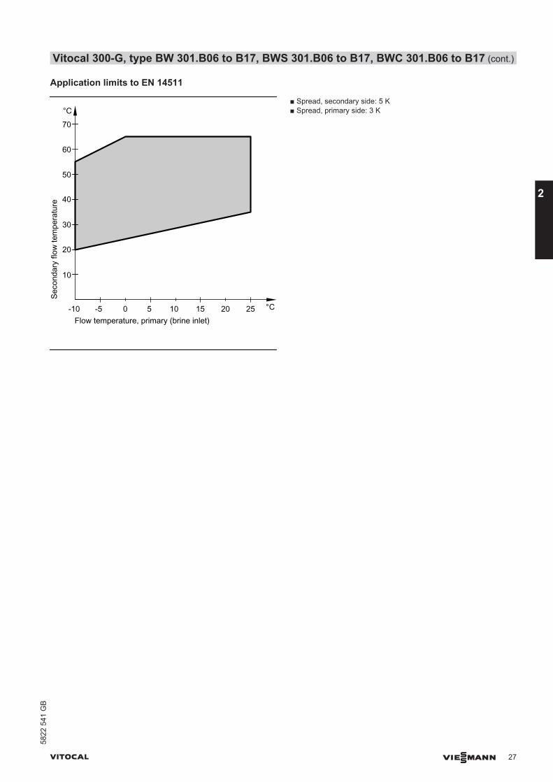
Application limits to EN 14511
Seco
ndar
y flo
w te
mpe
ratu
re
Flow temperature, primary (brine inlet)-5 0 5
°C
°C10 15 20 25-10
10
20
30
40
50
60
70
■ Spread, secondary side: 5 K■ Spread, primary side: 3 K
Vitocal 300-G, type BW 301.B06 to B17, BWS 301.B06 to B17, BWC 301.B06 to B17 (cont.)
VITOCAL VIESMANN 27
5822
541
GB
2
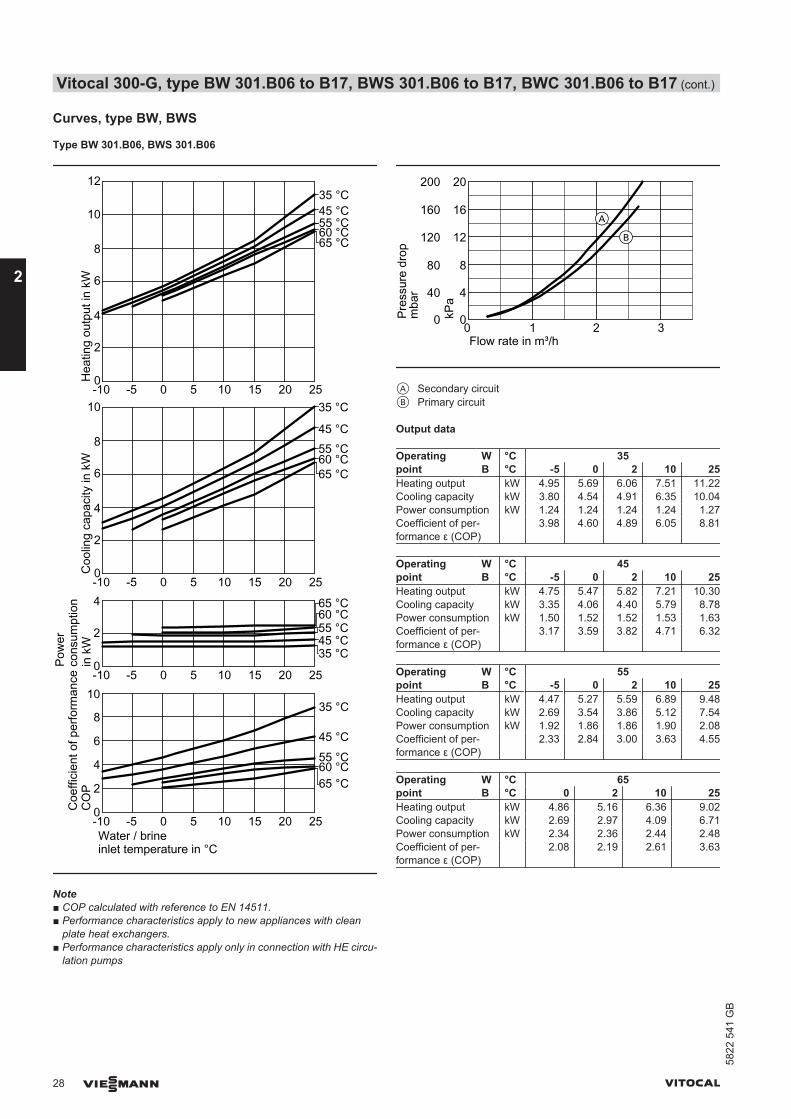
Curves, type BW, BWS
Type BW 301.B06, BWS 301.B06
0
2
-10 -5 0 5 10 15 20 25
-10 -5 0 5 10 15 20 250
2
4
6
8
Water / brineinlet temperature in °C
4
Coe
ffici
ent o
f per
form
ance
CO
PC
oolin
g ca
paci
ty in
kW
Pow
erco
nsum
ptio
n in
kW
Hea
ting
outp
ut in
kW
35 °C
45 °C
55 °C
65 °C
35 °C45 °C55 °C60 °C
0
2
10
-10 -5 0 5 10 15 20 25
4
6
8
0
2
10
-10 -5 0 5 10 15 20 25
12
4
6
8
35 °C
45 °C55 °C60 °C
35 °C45 °C55 °C60 °C
10
65 °C
65 °C
65 °C
60 °C
Note■ COP calculated with reference to EN 14511.■ Performance characteristics apply to new appliances with clean
plate heat exchangers.■ Performance characteristics apply only in connection with HE circu-
lation pumps
Pres
sure
dro
p
Flow rate in m³/h
mba
r
kPa
0 1 2 3
4
8
12
16
20
0
40
80
120
160
200
0
A
B
A Secondary circuitB Primary circuit
Output data
Operatingpoint
W °C 35B °C -5 0 2 10 25
Heating output kW 4.95 5.69 6.06 7.51 11.22Cooling capacity kW 3.80 4.54 4.91 6.35 10.04Power consumption kW 1.24 1.24 1.24 1.24 1.27Coefficient of per-formance ε (COP)
3.98 4.60 4.89 6.05 8.81
Operatingpoint
W °C 45B °C -5 0 2 10 25
Heating output kW 4.75 5.47 5.82 7.21 10.30Cooling capacity kW 3.35 4.06 4.40 5.79 8.78Power consumption kW 1.50 1.52 1.52 1.53 1.63Coefficient of per-formance ε (COP)
3.17 3.59 3.82 4.71 6.32
Operatingpoint
W °C 55B °C -5 0 2 10 25
Heating output kW 4.47 5.27 5.59 6.89 9.48Cooling capacity kW 2.69 3.54 3.86 5.12 7.54Power consumption kW 1.92 1.86 1.86 1.90 2.08Coefficient of per-formance ε (COP)
2.33 2.84 3.00 3.63 4.55
Operatingpoint
W °C 65B °C 0 2 10 25
Heating output kW 4.86 5.16 6.36 9.02Cooling capacity kW 2.69 2.97 4.09 6.71Power consumption kW 2.34 2.36 2.44 2.48Coefficient of per-formance ε (COP)
2.08 2.19 2.61 3.63
Vitocal 300-G, type BW 301.B06 to B17, BWS 301.B06 to B17, BWC 301.B06 to B17 (cont.)
28 VIESMANN VITOCAL
2
5822
541
GB
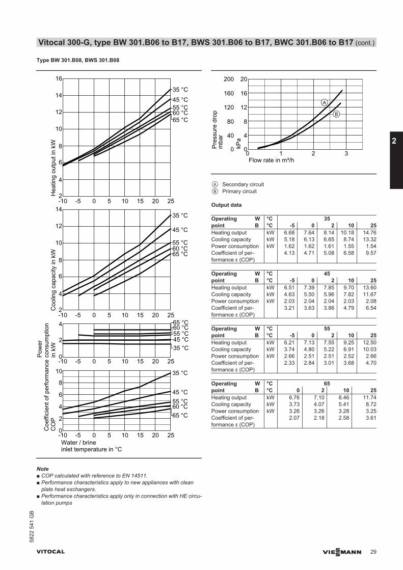
Type BW 301.B08, BWS 301.B08
0
2
-10 -5 0 5 10 15 20 25
-10 -5 0 5 10 15 20 250
2
4
6
8
Water / brineinlet temperature in °C
4
2
10
-10 -5 0 5 10 15 20 25
12
4
6
8
2
10
-10 -5 0 5 10 15 20 25
12
4
6
8
14
Coe
ffici
ent o
f per
form
ance
CO
PC
oolin
g ca
paci
ty in
kW
Pow
erco
nsum
ptio
n in
kW
Hea
ting
outp
ut in
kW
35 °C
45 °C55 °C60 °C
35 °C45 °C55 °C60 °C
35 °C
45 °C
55 °C60 °C
35 °C45 °C55 °C60 °C
10
65 °C
16
14
65 °C
65 °C
65 °C
Note■ COP calculated with reference to EN 14511.■ Performance characteristics apply to new appliances with clean
plate heat exchangers.■ Performance characteristics apply only in connection with HE circu-
lation pumps
Pres
sure
dro
p
Flow rate in m³/h
mba
r
kPa
0 1 2 3
4
8
12
16
20
0
40
80
120
160
200
0
A
B
A Secondary circuitB Primary circuit
Output data
Operatingpoint
W °C 35B °C -5 0 2 10 25
Heating output kW 6.68 7.64 8.14 10.18 14.76Cooling capacity kW 5.18 6.13 6.65 8.74 13.32Power consumption kW 1.62 1.62 1.61 1.55 1.54Coefficient of per-formance ε (COP)
4.13 4.71 5.08 6.58 9.57
Operatingpoint
W °C 45B °C -5 0 2 10 25
Heating output kW 6.51 7.39 7.85 9.70 13.60Cooling capacity kW 4.63 5.50 5.96 7.82 11.67Power consumption kW 2.03 2.04 2.04 2.03 2.08Coefficient of per-formance ε (COP)
3.21 3.63 3.86 4.79 6.54
Operatingpoint
W °C 55B °C -5 0 2 10 25
Heating output kW 6.21 7.13 7.55 9.25 12.50Cooling capacity kW 3.74 4.80 5.22 6.91 10.03Power consumption kW 2.66 2.51 2.51 2.52 2.66Coefficient of per-formance ε (COP)
2.33 2.84 3.01 3.68 4.70
Operatingpoint
W °C 65B °C 0 2 10 25
Heating output kW 6.76 7.10 8.46 11.74Cooling capacity kW 3.73 4.07 5.41 8.72Power consumption kW 3.26 3.26 3.28 3.25Coefficient of per-formance ε (COP)
2.07 2.18 2.58 3.61
Vitocal 300-G, type BW 301.B06 to B17, BWS 301.B06 to B17, BWC 301.B06 to B17 (cont.)
VITOCAL VIESMANN 29
5822
541
GB
2

Type BW 301.B10, BWS 301.B10
0
2
-10 -5 0 5 10 15 20 25
-10 -5 0 5 10 15 20 250
2
4
6
8
Water / brineinlet temperature in °C
4
10
Coe
ffici
ent o
f per
form
ance
CO
PC
oolin
g ca
paci
ty in
kW
Pow
erco
nsum
ptio
n in
kW
Hea
ting
outp
ut in
kW
35 °C
45 °C55 °C60 °C
35 °C45 °C55 °C60 °C
10
-10 -5 0 5 10 15 20 25
12
4
6
8
14
16
18
20
10
-10 -5 0 5 10 15 20 25
12
4
6
8
14
16
35 °C
45 °C
55 °C60 °C
35 °C
45 °C
55 °C60 °C
18
6
65 °C
65 °C
65 °C
65 °C
Note■ COP calculated with reference to EN 14511.■ Performance characteristics apply to new appliances with clean
plate heat exchangers.■ Performance characteristics apply only in connection with HE circu-
lation pumps
Pres
sure
dro
pFlow rate in m³/h
mba
r
kPa
0 1 2 3
4
8
12
16
20
0
40
80
120
160
200
0
A
B
A Secondary circuitB Primary circuit
Output data
Operatingpoint
W °C 35B °C -5 0 2 10 25
Heating output kW 9.02 10.36 10.99 13.51 19.86Cooling capacity kW 7.10 8.43 9.07 11.60 17.94Power consumption kW 2.06 2.07 2.07 2.05 2.06Coefficient of per-formance ε (COP)
4.38 5.01 5.32 6.58 9.63
Operatingpoint
W °C 45B °C -5 0 2 10 25
Heating output kW 8.72 9.99 10.58 12.95 18.35Cooling capacity kW 6.36 7.60 8.19 10.54 15.85Power consumption kW 2.54 2.57 2.58 2.59 2.68Coefficient of per-formance ε (COP)
3.43 3.88 4.11 5.00 6.84
Operatingpoint
W °C 55B °C -5 0 2 10 25
Heating output kW 8.28 9.56 10.11 12.28 16.78Cooling capacity kW 5.18 6.63 7.16 9.29 13.61Power consumption kW 3.33 3.15 3.17 3.22 3.41Coefficient of per-formance ε (COP)
2.48 3.03 3.19 3.82 4.92
Operatingpoint
W °C 65B °C 0 2 10 25
Heating output kW 8.89 9.37 11.29 15.61Cooling capacity kW 5.13 5.59 7.42 11.69Power consumption kW 4.04 4.07 4.17 4.21Coefficient of per-formance ε (COP)
2.20 2.30 2.71 3.71
Vitocal 300-G, type BW 301.B06 to B17, BWS 301.B06 to B17, BWC 301.B06 to B17 (cont.)
30 VIESMANN VITOCAL
2
5822
541
GB
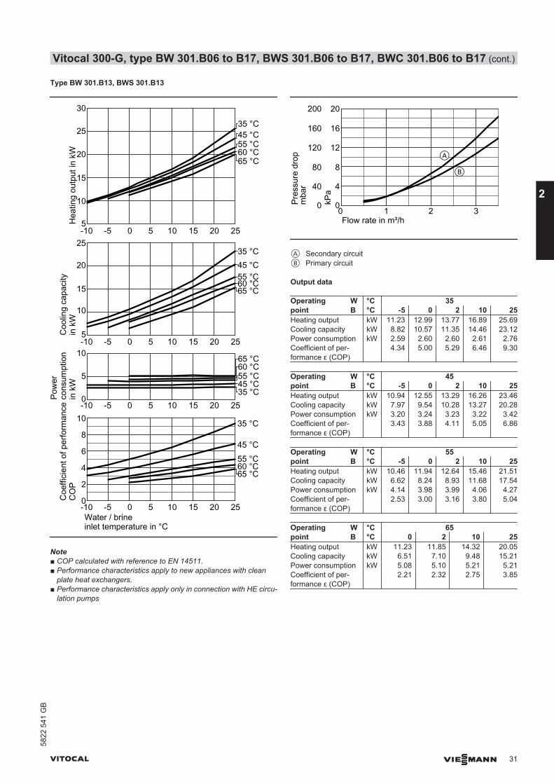
Type BW 301.B13, BWS 301.B13
0
5
10
-10 -5 0 5 10 15 20 25
-10 -5 0 5 10 15 20 250
2
4
6
8
Water / brineinlet temperature in °C
5
10
-10 -5 0 5 10 15 20 25
15
20
5
10
-10 -5 0 5 10 15 20 25
15
20
25
Coe
ffici
ent o
f per
form
ance
CO
PC
oolin
g ca
paci
ty
in k
W
Pow
erco
nsum
ptio
n in
kW
Hea
ting
outp
ut in
kW
35 °C
45 °C55 °C60 °C
35 °C45 °C55 °C60 °C
35 °C45 °C55 °C60 °C
35 °C45 °C55 °C60 °C
30
25
10
65 °C
65 °C
65 °C
65 °C
Note■ COP calculated with reference to EN 14511.■ Performance characteristics apply to new appliances with clean
plate heat exchangers.■ Performance characteristics apply only in connection with HE circu-
lation pumps
Pres
sure
dro
p
Flow rate in m³/h
mba
r
kPa
0 1 2 3
4
8
12
16
20
0
40
80
120
160
200
0
A
B
A Secondary circuitB Primary circuit
Output data
Operatingpoint
W °C 35B °C -5 0 2 10 25
Heating output kW 11.23 12.99 13.77 16.89 25.69Cooling capacity kW 8.82 10.57 11.35 14.46 23.12Power consumption kW 2.59 2.60 2.60 2.61 2.76Coefficient of per-formance ε (COP)
4.34 5.00 5.29 6.46 9.30
Operatingpoint
W °C 45B °C -5 0 2 10 25
Heating output kW 10.94 12.55 13.29 16.26 23.46Cooling capacity kW 7.97 9.54 10.28 13.27 20.28Power consumption kW 3.20 3.24 3.23 3.22 3.42Coefficient of per-formance ε (COP)
3.43 3.88 4.11 5.05 6.86
Operatingpoint
W °C 55B °C -5 0 2 10 25
Heating output kW 10.46 11.94 12.64 15.46 21.51Cooling capacity kW 6.62 8.24 8.93 11.68 17.54Power consumption kW 4.14 3.98 3.99 4.06 4.27Coefficient of per-formance ε (COP)
2.53 3.00 3.16 3.80 5.04
Operatingpoint
W °C 65B °C 0 2 10 25
Heating output kW 11.23 11.85 14.32 20.05Cooling capacity kW 6.51 7.10 9.48 15.21Power consumption kW 5.08 5.10 5.21 5.21Coefficient of per-formance ε (COP)
2.21 2.32 2.75 3.85
Vitocal 300-G, type BW 301.B06 to B17, BWS 301.B06 to B17, BWC 301.B06 to B17 (cont.)
VITOCAL VIESMANN 31
5822
541
GB
2
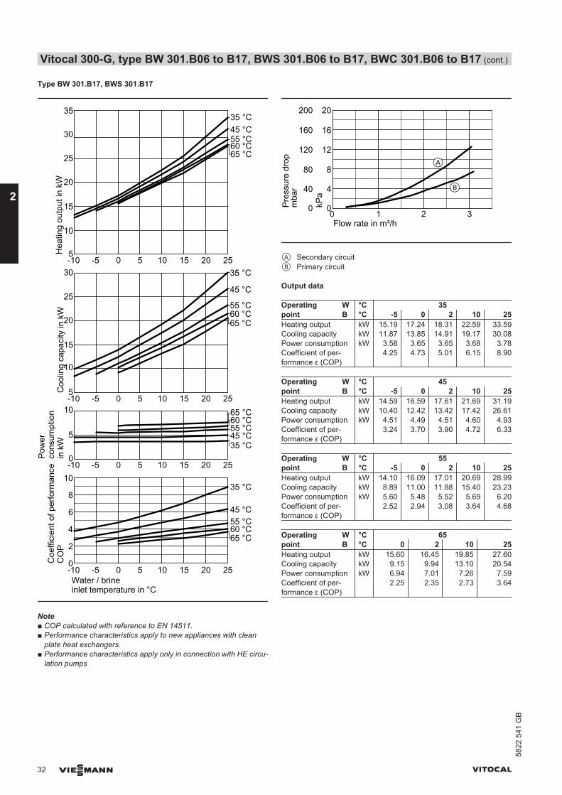
Type BW 301.B17, BWS 301.B17
0
5
10
-10 -5 0 5 10 15 20 25
-10 -5 0 5 10 15 20 250
2
4
6
8
Water / brineinlet temperature in °C
Coe
ffici
ent o
f per
form
ance
CO
PC
oolin
g ca
paci
ty in
kW
Pow
erco
nsum
ptio
n in
kW
Hea
ting
outp
ut in
kW
35 °C
45 °C55 °C60 °C
35 °C45 °C55 °C60 °C
5
10
-10 -5 0 5 10 15 20 25
15
20
25
5
10
-10 -5 0 5 10 15 20 25
15
20
25
30
35 °C
45 °C
55 °C60 °C
35 °C45 °C55 °C60 °C
30
35
65 °C
65 °C
65 °C
65 °C
10
Note■ COP calculated with reference to EN 14511.■ Performance characteristics apply to new appliances with clean
plate heat exchangers.■ Performance characteristics apply only in connection with HE circu-
lation pumps
Pres
sure
dro
p
Flow rate in m³/h
mba
r
kPa
0 1 2 3
4
8
12
16
20
0
40
80
120
160
200
0
A
B
A Secondary circuitB Primary circuit
Output data
Operatingpoint
W °C 35B °C -5 0 2 10 25
Heating output kW 15.19 17.24 18.31 22.59 33.59Cooling capacity kW 11.87 13.85 14.91 19.17 30.08Power consumption kW 3.58 3.65 3.65 3.68 3.78Coefficient of per-formance ε (COP)
4.25 4.73 5.01 6.15 8.90
Operatingpoint
W °C 45B °C -5 0 2 10 25
Heating output kW 14.59 16.59 17.61 21.69 31.19Cooling capacity kW 10.40 12.42 13.42 17.42 26.61Power consumption kW 4.51 4.49 4.51 4.60 4.93Coefficient of per-formance ε (COP)
3.24 3.70 3.90 4.72 6.33
Operatingpoint
W °C 55B °C -5 0 2 10 25
Heating output kW 14.10 16.09 17.01 20.69 28.99Cooling capacity kW 8.89 11.00 11.88 15.40 23.23Power consumption kW 5.60 5.48 5.52 5.69 6.20Coefficient of per-formance ε (COP)
2.52 2.94 3.08 3.64 4.68
Operatingpoint
W °C 65B °C 0 2 10 25
Heating output kW 15.60 16.45 19.85 27.60Cooling capacity kW 9.15 9.94 13.10 20.54Power consumption kW 6.94 7.01 7.26 7.59Coefficient of per-formance ε (COP)
2.25 2.35 2.73 3.64
Vitocal 300-G, type BW 301.B06 to B17, BWS 301.B06 to B17, BWC 301.B06 to B17 (cont.)
32 VIESMANN VITOCAL
2
5822
541
GB
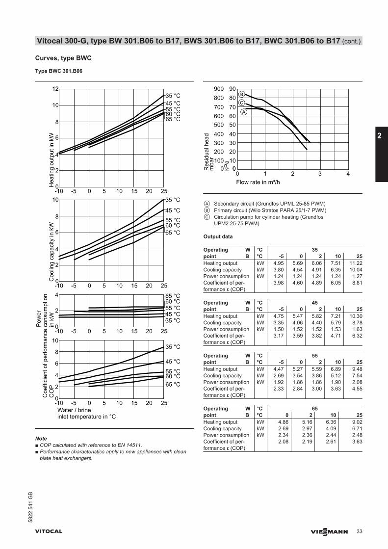
Curves, type BWC
Type BWC 301.B06
0
2
-10 -5 0 5 10 15 20 25
-10 -5 0 5 10 15 20 250
2
4
6
8
Water / brineinlet temperature in °C
4
Coe
ffici
ent o
f per
form
ance
CO
PC
oolin
g ca
paci
ty in
kW
Pow
erco
nsum
ptio
n in
kW
Hea
ting
outp
ut in
kW
35 °C
45 °C
55 °C
65 °C
35 °C45 °C55 °C60 °C
0
2
10
-10 -5 0 5 10 15 20 25
4
6
8
0
2
10
-10 -5 0 5 10 15 20 25
12
4
6
8
35 °C
45 °C55 °C60 °C
35 °C45 °C55 °C60 °C
10
65 °C
65 °C
65 °C
60 °C
Note■ COP calculated with reference to EN 14511.■ Performance characteristics apply to new appliances with clean
plate heat exchangers.
0 1 2 3 4Flow rate in m³/h
0100
300
500
700
0
200
400
600
800
Res
idua
l hea
dm
bar 10
30
50
70
0
20
40
60
80
kPa
B
A
900 90
C
A Secondary circuit (Grundfos UPML 25-85 PWM)B Primary circuit (Wilo Stratos PARA 25/1-7 PWM)C Circulation pump for cylinder heating (Grundfos
UPM2 25-75 PWM)
Output data
Operatingpoint
W °C 35B °C -5 0 2 10 25
Heating output kW 4.95 5.69 6.06 7.51 11.22Cooling capacity kW 3.80 4.54 4.91 6.35 10.04Power consumption kW 1.24 1.24 1.24 1.24 1.27Coefficient of per-formance ε (COP)
3.98 4.60 4.89 6.05 8.81
Operatingpoint
W °C 45B °C -5 0 2 10 25
Heating output kW 4.75 5.47 5.82 7.21 10.30Cooling capacity kW 3.35 4.06 4.40 5.79 8.78Power consumption kW 1.50 1.52 1.52 1.53 1.63Coefficient of per-formance ε (COP)
3.17 3.59 3.82 4.71 6.32
Operatingpoint
W °C 55B °C -5 0 2 10 25
Heating output kW 4.47 5.27 5.59 6.89 9.48Cooling capacity kW 2.69 3.54 3.86 5.12 7.54Power consumption kW 1.92 1.86 1.86 1.90 2.08Coefficient of per-formance ε (COP)
2.33 2.84 3.00 3.63 4.55
Operatingpoint
W °C 65B °C 0 2 10 25
Heating output kW 4.86 5.16 6.36 9.02Cooling capacity kW 2.69 2.97 4.09 6.71Power consumption kW 2.34 2.36 2.44 2.48Coefficient of per-formance ε (COP)
2.08 2.19 2.61 3.63
Vitocal 300-G, type BW 301.B06 to B17, BWS 301.B06 to B17, BWC 301.B06 to B17 (cont.)
VITOCAL VIESMANN 33
5822
541
GB
2
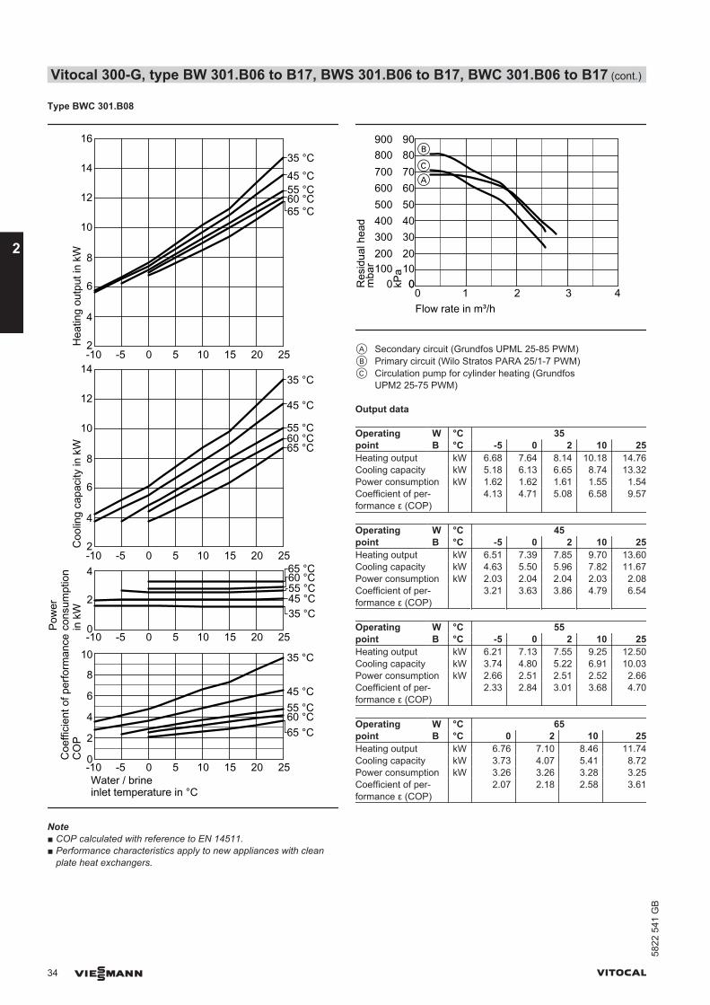
Type BWC 301.B08
0
2
-10 -5 0 5 10 15 20 25
-10 -5 0 5 10 15 20 250
2
4
6
8
Water / brineinlet temperature in °C
4
2
10
-10 -5 0 5 10 15 20 25
12
4
6
8
2
10
-10 -5 0 5 10 15 20 25
12
4
6
8
14
Coe
ffici
ent o
f per
form
ance
CO
PC
oolin
g ca
paci
ty in
kW
Pow
erco
nsum
ptio
n in
kW
Hea
ting
outp
ut in
kW
35 °C
45 °C55 °C60 °C
35 °C45 °C55 °C60 °C
35 °C
45 °C
55 °C60 °C
35 °C45 °C55 °C60 °C
10
65 °C
16
14
65 °C
65 °C
65 °C
Note■ COP calculated with reference to EN 14511.■ Performance characteristics apply to new appliances with clean
plate heat exchangers.
0 1 2 3 4Flow rate in m³/h
0100
300
500
700
0
200
400
600
800
Res
idua
l hea
dm
bar 10
30
50
70
0
20
40
60
80
kPa
900 90
C
B
A
A Secondary circuit (Grundfos UPML 25-85 PWM)B Primary circuit (Wilo Stratos PARA 25/1-7 PWM)C Circulation pump for cylinder heating (Grundfos
UPM2 25-75 PWM)
Output data
Operatingpoint
W °C 35B °C -5 0 2 10 25
Heating output kW 6.68 7.64 8.14 10.18 14.76Cooling capacity kW 5.18 6.13 6.65 8.74 13.32Power consumption kW 1.62 1.62 1.61 1.55 1.54Coefficient of per-formance ε (COP)
4.13 4.71 5.08 6.58 9.57
Operatingpoint
W °C 45B °C -5 0 2 10 25
Heating output kW 6.51 7.39 7.85 9.70 13.60Cooling capacity kW 4.63 5.50 5.96 7.82 11.67Power consumption kW 2.03 2.04 2.04 2.03 2.08Coefficient of per-formance ε (COP)
3.21 3.63 3.86 4.79 6.54
Operatingpoint
W °C 55B °C -5 0 2 10 25
Heating output kW 6.21 7.13 7.55 9.25 12.50Cooling capacity kW 3.74 4.80 5.22 6.91 10.03Power consumption kW 2.66 2.51 2.51 2.52 2.66Coefficient of per-formance ε (COP)
2.33 2.84 3.01 3.68 4.70
Operatingpoint
W °C 65B °C 0 2 10 25
Heating output kW 6.76 7.10 8.46 11.74Cooling capacity kW 3.73 4.07 5.41 8.72Power consumption kW 3.26 3.26 3.28 3.25Coefficient of per-formance ε (COP)
2.07 2.18 2.58 3.61
Vitocal 300-G, type BW 301.B06 to B17, BWS 301.B06 to B17, BWC 301.B06 to B17 (cont.)
34 VIESMANN VITOCAL
2
5822
541
GB

Type BWC 301.B10
0
2
-10 -5 0 5 10 15 20 25
-10 -5 0 5 10 15 20 250
2
4
6
8
Water / brineinlet temperature in °C
4
10
Coe
ffici
ent o
f per
form
ance
CO
PC
oolin
g ca
paci
ty in
kW
Pow
erco
nsum
ptio
n in
kW
Hea
ting
outp
ut in
kW
35 °C
45 °C55 °C60 °C
35 °C45 °C55 °C60 °C
10
-10 -5 0 5 10 15 20 25
12
4
6
8
14
16
18
20
10
-10 -5 0 5 10 15 20 25
12
4
6
8
14
16
35 °C
45 °C
55 °C60 °C
35 °C
45 °C
55 °C60 °C
18
6
65 °C
65 °C
65 °C
65 °C
Note■ COP calculated with reference to EN 14511.■ Performance characteristics apply to new appliances with clean
plate heat exchangers.
0 1 2 3 4Flow rate in m³/h
0100
300
500
700
0
200
400
600
800
Res
idua
l hea
dm
bar 10
30
50
70
0
20
40
60
80
kPa
900 90
A
B
C
A Secondary circuit (Grundfos UPML 25-85 PWM)B Primary circuit (Wilo Stratos PARA 25/1-7 PWM)C Circulation pump for cylinder heating (Grundfos
UPM2 25-75 PWM)
Output data
Operatingpoint
W °C 35B °C -5 0 2 10 25
Heating output kW 9.02 10.36 10.99 13.51 19.86Cooling capacity kW 7.10 8.43 9.07 11.60 17.94Power consumption kW 2.06 2.07 2.07 2.05 2.06Coefficient of per-formance ε (COP)
4.38 5.01 5.32 6.58 9.63
Operatingpoint
W °C 45B °C -5 0 2 10 25
Heating output kW 8.72 9.99 10.58 12.95 18.35Cooling capacity kW 6.36 7.60 8.19 10.54 15.85Power consumption kW 2.54 2.57 2.58 2.59 2.68Coefficient of per-formance ε (COP)
3.43 3.88 4.11 5.00 6.84
Operatingpoint
W °C 55B °C -5 0 2 10 25
Heating output kW 8.28 9.56 10.11 12.28 16.78Cooling capacity kW 5.18 6.63 7.16 9.29 13.61Power consumption kW 3.33 3.15 3.17 3.22 3.41Coefficient of per-formance ε (COP)
2.48 3.03 3.19 3.82 4.92
Operatingpoint
W °C 65B °C 0 2 10 25
Heating output kW 8.89 9.37 11.29 15.61Cooling capacity kW 5.13 5.59 7.42 11.69Power consumption kW 4.04 4.07 4.17 4.21Coefficient of per-formance ε (COP)
2.20 2.30 2.71 3.71
Vitocal 300-G, type BW 301.B06 to B17, BWS 301.B06 to B17, BWC 301.B06 to B17 (cont.)
VITOCAL VIESMANN 35
5822
541
GB
2
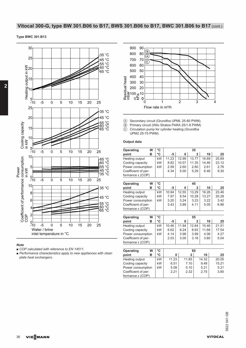
Type BWC 301.B13
0
5
10
-10 -5 0 5 10 15 20 25
-10 -5 0 5 10 15 20 250
2
4
6
8
Water / brineinlet temperature in °C
5
10
-10 -5 0 5 10 15 20 25
15
20
5
10
-10 -5 0 5 10 15 20 25
15
20
25
Coe
ffici
ent o
f per
form
ance
CO
PC
oolin
g ca
paci
ty
in k
W
Pow
erco
nsum
ptio
n in
kW
Hea
ting
outp
ut in
kW
35 °C
45 °C55 °C60 °C
35 °C45 °C55 °C60 °C
35 °C45 °C55 °C60 °C
35 °C45 °C55 °C60 °C
30
25
10
65 °C
65 °C
65 °C
65 °C
Note■ COP calculated with reference to EN 14511.■ Performance characteristics apply to new appliances with clean
plate heat exchangers.
0 1 2 3 4Flow rate in m³/h
0100
300
500
700
0
200
400
600
800
Res
idua
l hea
dm
bar 10
30
50
70
0
20
40
60
80
kPa
BA
900 90
C
A Secondary circuit (Grundfos UPML 25-85 PWM)B Primary circuit (Wilo Stratos PARA 25/1-8 PWM)C Circulation pump for cylinder heating (Grundfos
UPM2 25-75 PWM)
Output data
Operatingpoint
W °C 35B °C -5 0 2 10 25
Heating output kW 11.23 12.99 13.77 16.89 25.69Cooling capacity kW 8.82 10.57 11.35 14.46 23.12Power consumption kW 2.59 2.60 2.60 2.61 2.76Coefficient of per-formance ε (COP)
4.34 5.00 5.29 6.46 9.30
Operatingpoint
W °C 45B °C -5 0 2 10 25
Heating output kW 10.94 12.55 13.29 16.26 23.46Cooling capacity kW 7.97 9.54 10.28 13.27 20.28Power consumption kW 3.20 3.24 3.23 3.22 3.42Coefficient of per-formance ε (COP)
3.43 3.88 4.11 5.05 6.86
Operatingpoint
W °C 55B °C -5 0 2 10 25
Heating output kW 10.46 11.94 12.64 15.46 21.51Cooling capacity kW 6.62 8.24 8.93 11.68 17.54Power consumption kW 4.14 3.98 3.99 4.06 4.27Coefficient of per-formance ε (COP)
2.53 3.00 3.16 3.80 5.04
Operatingpoint
W °C 65B °C 0 2 10 25
Heating output kW 11.23 11.85 14.32 20.05Cooling capacity kW 6.51 7.10 9.48 15.21Power consumption kW 5.08 5.10 5.21 5.21Coefficient of per-formance ε (COP)
2.21 2.32 2.75 3.85
Vitocal 300-G, type BW 301.B06 to B17, BWS 301.B06 to B17, BWC 301.B06 to B17 (cont.)
36 VIESMANN VITOCAL
2
5822
541
GB
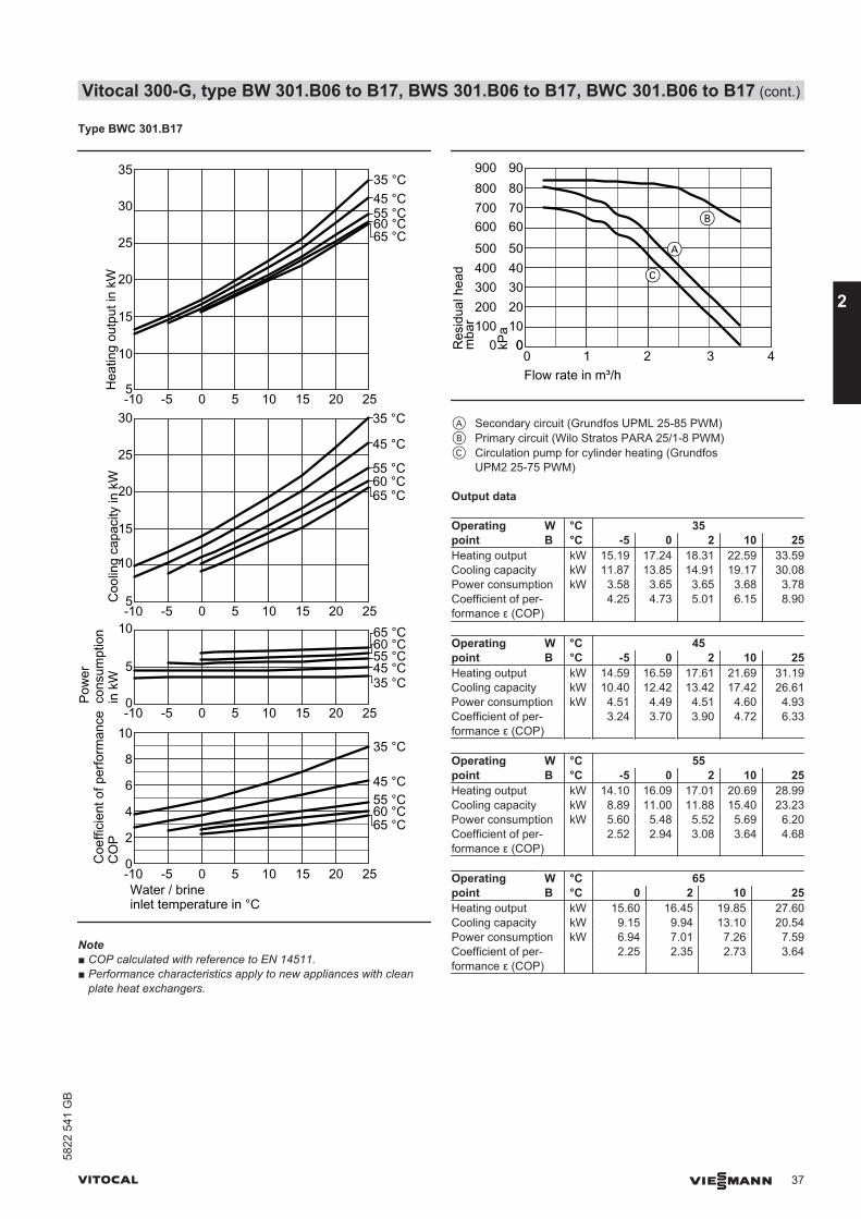
Type BWC 301.B17
0
5
10
-10 -5 0 5 10 15 20 25
-10 -5 0 5 10 15 20 250
2
4
6
8
Water / brineinlet temperature in °C
Coe
ffici
ent o
f per
form
ance
CO
PC
oolin
g ca
paci
ty in
kW
Pow
erco
nsum
ptio
n in
kW
Hea
ting
outp
ut in
kW
35 °C
45 °C55 °C60 °C
35 °C45 °C55 °C60 °C
5
10
-10 -5 0 5 10 15 20 25
15
20
25
5
10
-10 -5 0 5 10 15 20 25
15
20
25
30
35 °C
45 °C
55 °C60 °C
35 °C45 °C55 °C60 °C
30
35
65 °C
65 °C
65 °C
65 °C
10
Note■ COP calculated with reference to EN 14511.■ Performance characteristics apply to new appliances with clean
plate heat exchangers.
0 1 2 3 4Flow rate in m³/h
0100
300
500
700
0
200
400
600
800
Res
idua
l hea
dm
bar 10
30
50
70
0
20
40
60
80
kPa
900 90
A
B
C
A Secondary circuit (Grundfos UPML 25-85 PWM)B Primary circuit (Wilo Stratos PARA 25/1-8 PWM)C Circulation pump for cylinder heating (Grundfos
UPM2 25-75 PWM)
Output data
Operatingpoint
W °C 35B °C -5 0 2 10 25
Heating output kW 15.19 17.24 18.31 22.59 33.59Cooling capacity kW 11.87 13.85 14.91 19.17 30.08Power consumption kW 3.58 3.65 3.65 3.68 3.78Coefficient of per-formance ε (COP)
4.25 4.73 5.01 6.15 8.90
Operatingpoint
W °C 45B °C -5 0 2 10 25
Heating output kW 14.59 16.59 17.61 21.69 31.19Cooling capacity kW 10.40 12.42 13.42 17.42 26.61Power consumption kW 4.51 4.49 4.51 4.60 4.93Coefficient of per-formance ε (COP)
3.24 3.70 3.90 4.72 6.33
Operatingpoint
W °C 55B °C -5 0 2 10 25
Heating output kW 14.10 16.09 17.01 20.69 28.99Cooling capacity kW 8.89 11.00 11.88 15.40 23.23Power consumption kW 5.60 5.48 5.52 5.69 6.20Coefficient of per-formance ε (COP)
2.52 2.94 3.08 3.64 4.68
Operatingpoint
W °C 65B °C 0 2 10 25
Heating output kW 15.60 16.45 19.85 27.60Cooling capacity kW 9.15 9.94 13.10 20.54Power consumption kW 6.94 7.01 7.26 7.59Coefficient of per-formance ε (COP)
2.25 2.35 2.73 3.64
Vitocal 300-G, type BW 301.B06 to B17, BWS 301.B06 to B17, BWC 301.B06 to B17 (cont.)
VITOCAL VIESMANN 37
5822
541
GB
2
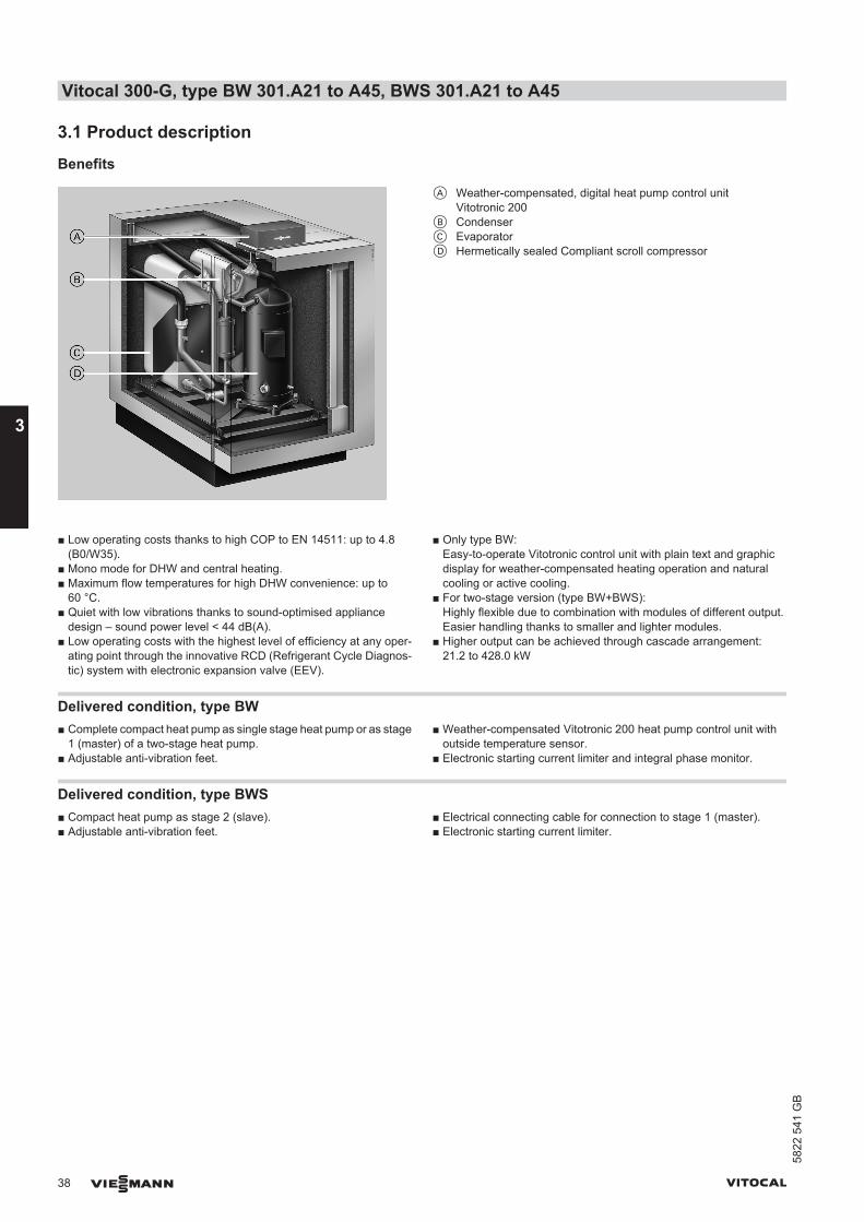
3.1 Product description
Benefits
A Weather-compensated, digital heat pump control unitVitotronic 200
B CondenserC EvaporatorD Hermetically sealed Compliant scroll compressor
■ Low operating costs thanks to high COP to EN 14511: up to 4.8(B0/W35).
■ Mono mode for DHW and central heating.■ Maximum flow temperatures for high DHW convenience: up to
60 °C.■ Quiet with low vibrations thanks to sound-optimised appliance
design – sound power level < 44 dB(A).■ Low operating costs with the highest level of efficiency at any oper-
ating point through the innovative RCD (Refrigerant Cycle Diagnos-tic) system with electronic expansion valve (EEV).
■ Only type BW:Easy-to-operate Vitotronic control unit with plain text and graphicdisplay for weather-compensated heating operation and naturalcooling or active cooling.
■ For two-stage version (type BW+BWS):Highly flexible due to combination with modules of different output.Easier handling thanks to smaller and lighter modules.
■ Higher output can be achieved through cascade arrangement:21.2 to 428.0 kW
Delivered condition, type BW■ Complete compact heat pump as single stage heat pump or as stage
1 (master) of a two-stage heat pump.■ Adjustable anti-vibration feet.
■ Weather-compensated Vitotronic 200 heat pump control unit withoutside temperature sensor.
■ Electronic starting current limiter and integral phase monitor.
Delivered condition, type BWS■ Compact heat pump as stage 2 (slave).■ Adjustable anti-vibration feet.
■ Electrical connecting cable for connection to stage 1 (master).■ Electronic starting current limiter.
Vitocal 300-G, type BW 301.A21 to A45, BWS 301.A21 to A45
38 VIESMANN VITOCAL
3
5822
541
GB
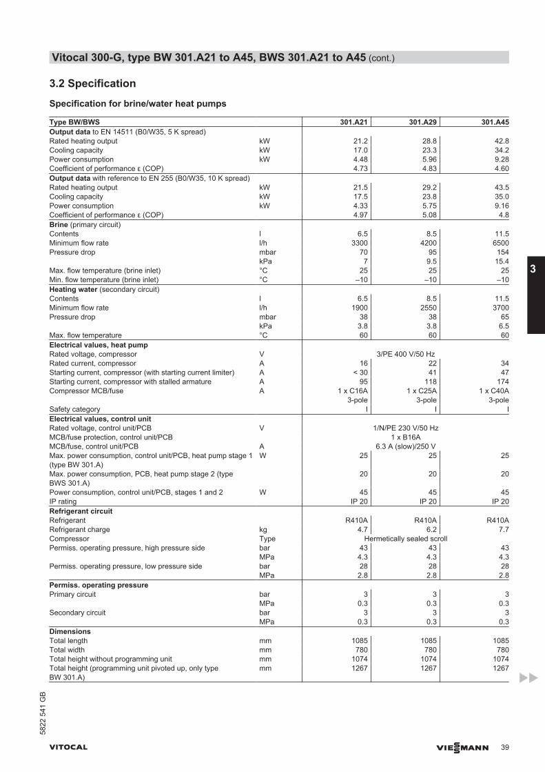
3.2 Specification
Specification for brine/water heat pumps
Type BW/BWS 301.A21 301.A29 301.A45Output data to EN 14511 (B0/W35, 5 K spread) Rated heating output kW 21.2 28.8 42.8Cooling capacity kW 17.0 23.3 34.2Power consumption kW 4.48 5.96 9.28Coefficient of performance ε (COP) 4.73 4.83 4.60Output data with reference to EN 255 (B0/W35, 10 K spread) Rated heating output kW 21.5 29.2 43.5Cooling capacity kW 17.5 23.8 35.0Power consumption kW 4.33 5.75 9.16Coefficient of performance ε (COP) 4.97 5.08 4.8Brine (primary circuit) Contents l 6.5 8.5 11.5Minimum flow rate l/h 3300 4200 6500Pressure drop mbar 70 95 154 kPa 7 9.5 15.4Max. flow temperature (brine inlet) °C 25 25 25Min. flow temperature (brine inlet) °C –10 –10 –10Heating water (secondary circuit) Contents l 6.5 8.5 11.5Minimum flow rate l/h 1900 2550 3700Pressure drop mbar 38 38 65 kPa 3.8 3.8 6.5Max. flow temperature °C 60 60 60Electrical values, heat pump Rated voltage, compressor V 3/PE 400 V/50 HzRated current, compressor A 16 22 34Starting current, compressor (with starting current limiter) A < 30 41 47Starting current, compressor with stalled armature A 95 118 174Compressor MCB/fuse A 1 x C16A
3-pole1 x C25A
3-pole1 x C40A
3-poleSafety category I I IElectrical values, control unit Rated voltage, control unit/PCB V 1/N/PE 230 V/50 HzMCB/fuse protection, control unit/PCB 1 x B16AMCB/fuse, control unit/PCB A 6.3 A (slow)/250 VMax. power consumption, control unit/PCB, heat pump stage 1(type BW 301.A)
W 25 25 25
Max. power consumption, PCB, heat pump stage 2 (typeBWS 301.A)
20 20 20
Power consumption, control unit/PCB, stages 1 and 2 W 45 45 45IP rating IP 20 IP 20 IP 20Refrigerant circuit Refrigerant R410A R410A R410ARefrigerant charge kg 4.7 6.2 7.7Compressor Type Hermetically sealed scrollPermiss. operating pressure, high pressure side bar 43 43 43 MPa 4.3 4.3 4.3Permiss. operating pressure, low pressure side bar 28 28 28 MPa 2.8 2.8 2.8Permiss. operating pressure Primary circuit bar 3 3 3 MPa 0.3 0.3 0.3Secondary circuit bar 3 3 3 MPa 0.3 0.3 0.3Dimensions Total length mm 1085 1085 1085Total width mm 780 780 780Total height without programming unit mm 1074 1074 1074Total height (programming unit pivoted up, only typeBW 301.A)
mm 1267 1267 1267
Vitocal 300-G, type BW 301.A21 to A45, BWS 301.A21 to A45 (cont.)
VITOCAL VIESMANN 39
5822
541
GB
3
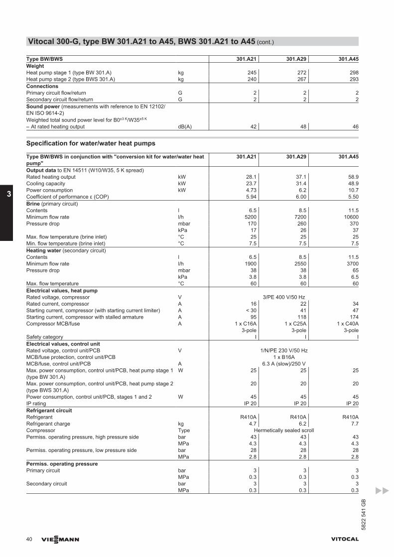
Type BW/BWS 301.A21 301.A29 301.A45Weight Heat pump stage 1 (type BW 301.A) kg 245 272 298Heat pump stage 2 (type BWS 301.A) kg 240 267 293Connections Primary circuit flow/return G 2 2 2Secondary circuit flow/return G 2 2 2Sound power (measurements with reference to EN 12102/EN ISO 9614-2)Weighted total sound power level for B0±3 K/W35±5 K
– At rated heating output dB(A) 42 48 46
Specification for water/water heat pumps
Type BW/BWS in conjunction with "conversion kit for water/water heatpump"
301.A21 301.A29 301.A45
Output data to EN 14511 (W10/W35, 5 K spread) Rated heating output kW 28.1 37.1 58.9Cooling capacity kW 23.7 31.4 48.9Power consumption kW 4.73 6.2 10.7Coefficient of performance ε (COP) 5.94 6.00 5.50Brine (primary circuit) Contents l 6.5 8.5 11.5Minimum flow rate l/h 5200 7200 10600Pressure drop mbar 170 260 370 kPa 17 26 37Max. flow temperature (brine inlet) °C 25 25 25Min. flow temperature (brine inlet) °C 7.5 7.5 7.5Heating water (secondary circuit) Contents l 6.5 8.5 11.5Minimum flow rate l/h 1900 2550 3700Pressure drop mbar 38 38 65 kPa 3.8 3.8 6.5Max. flow temperature °C 60 60 60Electrical values, heat pump Rated voltage, compressor V 3/PE 400 V/50 HzRated current, compressor A 16 22 34Starting current, compressor (with starting current limiter) A < 30 41 47Starting current, compressor with stalled armature A 95 118 174Compressor MCB/fuse A 1 x C16A
3-pole1 x C25A
3-pole1 x C40A
3-poleSafety category I I IElectrical values, control unit Rated voltage, control unit/PCB V 1/N/PE 230 V/50 HzMCB/fuse protection, control unit/PCB 1 x B16AMCB/fuse, control unit/PCB A 6.3 A (slow)/250 VMax. power consumption, control unit/PCB, heat pump stage 1(type BW 301.A)
W 25 25 25
Max. power consumption, control unit/PCB, heat pump stage 2(type BWS 301.A)
20 20 20
Power consumption, control unit/PCB, stages 1 and 2 W 45 45 45IP rating IP 20 IP 20 IP 20Refrigerant circuit Refrigerant R410A R410A R410ARefrigerant charge kg 4.7 6.2 7.7Compressor Type Hermetically sealed scrollPermiss. operating pressure, high pressure side bar 43 43 43 MPa 4.3 4.3 4.3Permiss. operating pressure, low pressure side bar 28 28 28 MPa 2.8 2.8 2.8Permiss. operating pressure Primary circuit bar 3 3 3 MPa 0.3 0.3 0.3Secondary circuit bar 3 3 3 MPa 0.3 0.3 0.3
Vitocal 300-G, type BW 301.A21 to A45, BWS 301.A21 to A45 (cont.)
40 VIESMANN VITOCAL
3
5822
541
GB
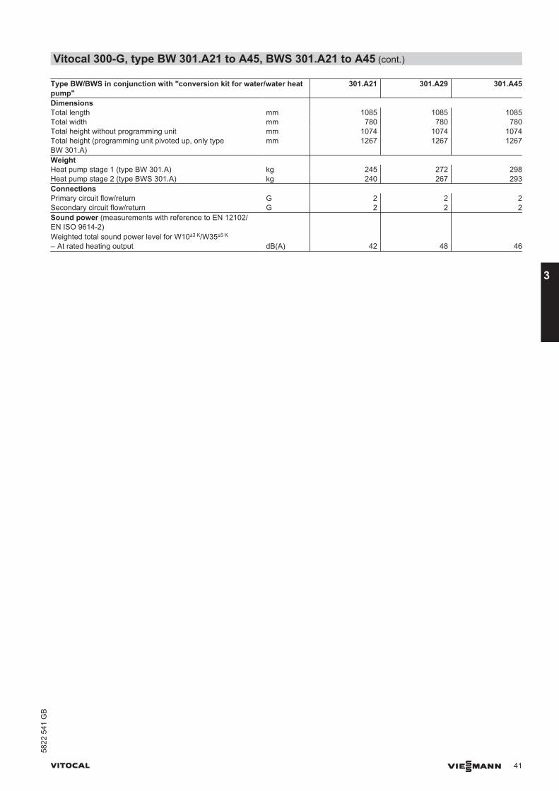
Type BW/BWS in conjunction with "conversion kit for water/water heatpump"
301.A21 301.A29 301.A45
Dimensions Total length mm 1085 1085 1085Total width mm 780 780 780Total height without programming unit mm 1074 1074 1074Total height (programming unit pivoted up, only typeBW 301.A)
mm 1267 1267 1267
Weight Heat pump stage 1 (type BW 301.A) kg 245 272 298Heat pump stage 2 (type BWS 301.A) kg 240 267 293Connections Primary circuit flow/return G 2 2 2Secondary circuit flow/return G 2 2 2Sound power (measurements with reference to EN 12102/EN ISO 9614-2)Weighted total sound power level for W10±3 K/W35±5 K
– At rated heating output dB(A) 42 48 46
Vitocal 300-G, type BW 301.A21 to A45, BWS 301.A21 to A45 (cont.)
VITOCAL VIESMANN 41
5822
541
GB
3
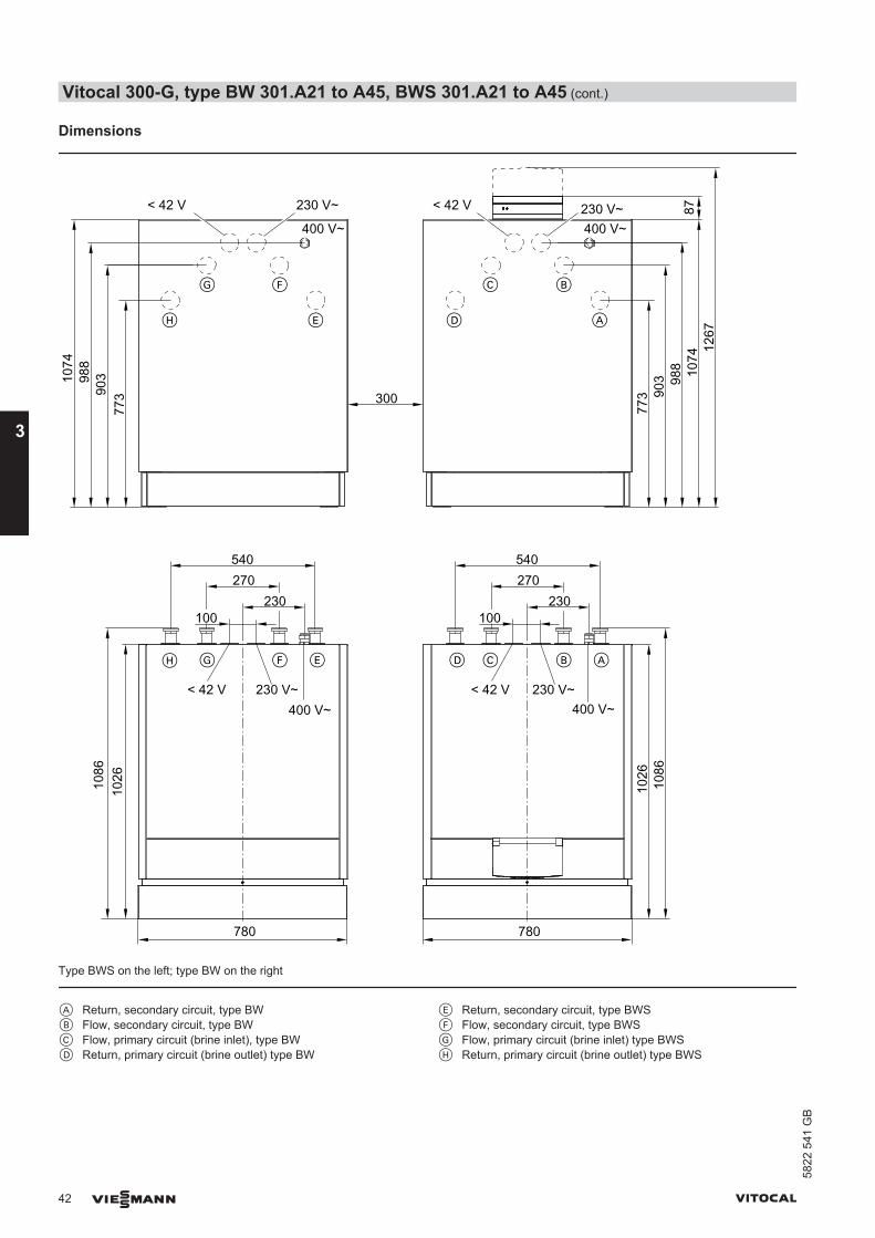
Dimensions
87
780 780
230
540270
1026
230
540270
773
773 300
400 V~
230 V~< 42 V
400 V~230 V~< 42 V
90398
810
74
1086
100
400 V~230 V~< 42 V
903 98
8 1074
1267
100
1026
1086
400 V~230 V~< 42 V
A
BC
DE
FG
H
BCFGH E D A
Type BWS on the left; type BW on the right
A Return, secondary circuit, type BWB Flow, secondary circuit, type BWC Flow, primary circuit (brine inlet), type BWD Return, primary circuit (brine outlet) type BW
E Return, secondary circuit, type BWSF Flow, secondary circuit, type BWSG Flow, primary circuit (brine inlet) type BWSH Return, primary circuit (brine outlet) type BWS
Vitocal 300-G, type BW 301.A21 to A45, BWS 301.A21 to A45 (cont.)
42 VIESMANN VITOCAL
3
5822
541
GB
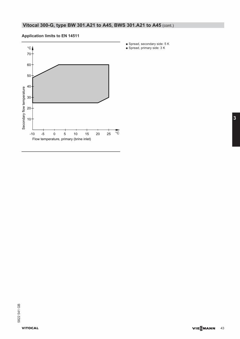
Application limits to EN 14511
Seco
ndar
y flo
w te
mpe
ratu
re
Flow temperature, primary (brine inlet)-5 0 5
°C
°C10 15 20 25-10
10
20
30
40
50
60
70
■ Spread, secondary side: 5 K■ Spread, primary side: 3 K
Vitocal 300-G, type BW 301.A21 to A45, BWS 301.A21 to A45 (cont.)
VITOCAL VIESMANN 43
5822
541
GB
3
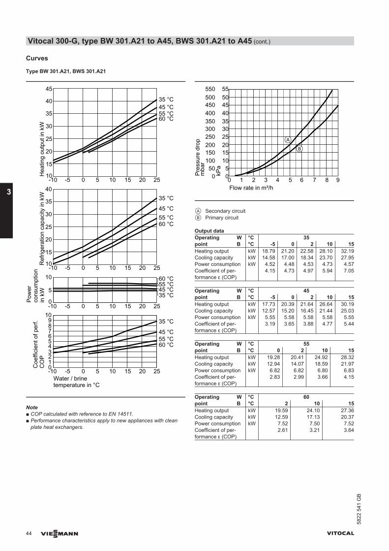
Curves
Type BW 301.A21, BWS 301.A21
Water / brinetemperature in °C
Coe
ffici
ent o
f per
f.C
OP
Ref
riger
atio
n ca
paci
ty in
kW
Pow
erco
nsum
ptio
n in
kW
Hea
ting
outp
ut in
kW
35 °C
45 °C55 °C60 °C
35 °C45 °C55 °C60 °C
35 °C
45 °C55 °C60 °C
35 °C45 °C55 °C60 °C
-10 -5 0 5 10 15 20 25
-10 -5 0 5 10 15 20 25
-10 -5 0 5 10 15 20 25
-10 -5 0 5 10 15 20 25
0123456789
10
0
5
10
10
15
20
25
30
35
40
10
15
20
25
30
35
40
45
Note■ COP calculated with reference to EN 14511.■ Performance characteristics apply to new appliances with clean
plate heat exchangers.
Pres
sure
dro
pFlow rate in m³/h
0 1 2 3 4 5 6 7 8 9050
100150200250300350400450500550
05
10152025303540455055
kPa
mba
r
A
B
A Secondary circuitB Primary circuit
Output dataOperatingpoint
W °C 35B °C -5 0 2 10 15
Heating output kW 18.79 21.20 22.58 28.10 32.19Cooling capacity kW 14.58 17.00 18.34 23.70 27.95Power consumption kW 4.52 4.48 4.53 4.73 4.57Coefficient of per-formance ε (COP)
4.15 4.73 4.97 5.94 7.05
Operatingpoint
W °C 45B °C -5 0 2 10 15
Heating output kW 17.73 20.39 21.64 26.64 30.19Cooling capacity kW 12.57 15.20 16.45 21.44 25.03Power consumption kW 5.55 5.58 5.58 5.58 5.55Coefficient of per-formance ε (COP)
3.19 3.65 3.88 4.77 5.44
Operatingpoint
W °C 55B °C 0 2 10 15
Heating output kW 19.28 20.41 24.92 28.32Cooling capacity kW 12.94 14.07 18.59 21.97Power consumption kW 6.82 6.82 6.80 6.83Coefficient of per-formance ε (COP)
2.83 2.99 3.66 4.15
Operatingpoint
W °C 60B °C 2 10 15
Heating output kW 19.59 24.10 27.36Cooling capacity kW 12.59 17.13 20.37Power consumption kW 7.52 7.50 7.52Coefficient of per-formance ε (COP)
2.61 3.21 3.64
Vitocal 300-G, type BW 301.A21 to A45, BWS 301.A21 to A45 (cont.)
44 VIESMANN VITOCAL
3
5822
541
GB
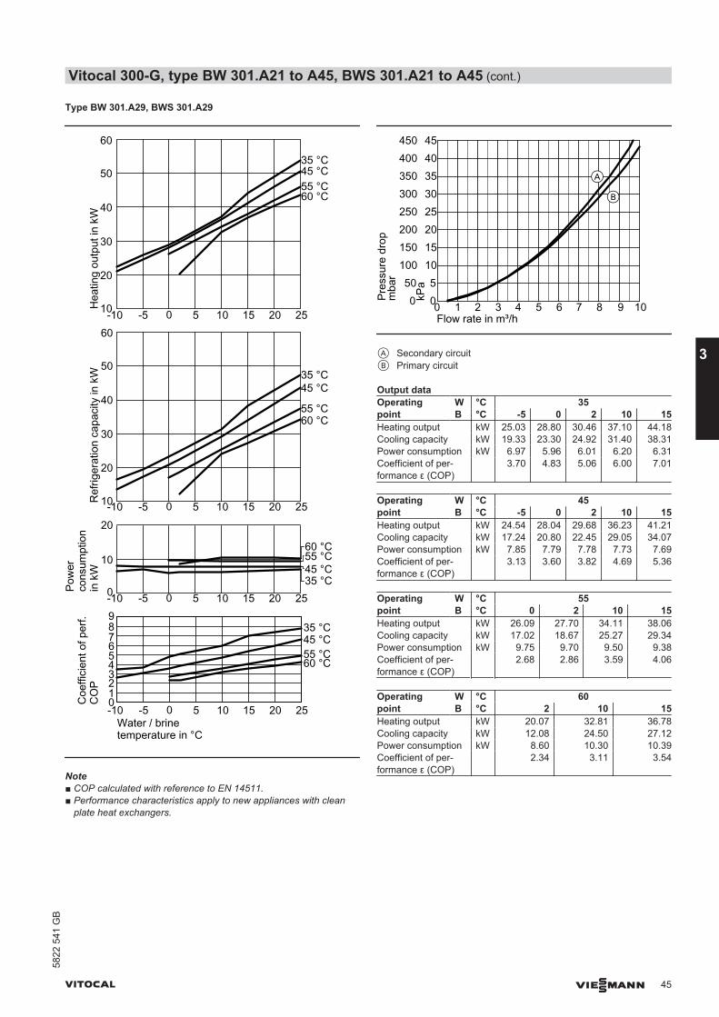
Type BW 301.A29, BWS 301.A29
Water / brinetemperature in °C
Coe
ffici
ent o
f per
f.C
OP
Ref
riger
atio
n ca
paci
ty in
kW
Pow
erco
nsum
ptio
n in
kW
Hea
ting
outp
ut in
kW
35 °C45 °C55 °C60 °C
35 °C45 °C55 °C60 °C
35 °C45 °C
55 °C60 °C
35 °C45 °C55 °C60 °C
-10 -5 0 5 10 15 20 25
-10 -5 0 5 10 15 20 25
-10 -5 0 5 10 15 20 25
-10 -5 0 5 10 15 20 25
0123456789
0
10
20
10
20
30
40
50
60
10
20
30
40
50
60
Note■ COP calculated with reference to EN 14511.■ Performance characteristics apply to new appliances with clean
plate heat exchangers.
Pres
sure
dro
p
Flow rate in m³/h
mba
r
kPa
4540353025201510500 1 2 3 4 5 6 7 8 9 10
A
B
450400350300250200150100500
A Secondary circuitB Primary circuit
Output dataOperatingpoint
W °C 35B °C -5 0 2 10 15
Heating output kW 25.03 28.80 30.46 37.10 44.18Cooling capacity kW 19.33 23.30 24.92 31.40 38.31Power consumption kW 6.97 5.96 6.01 6.20 6.31Coefficient of per-formance ε (COP)
3.70 4.83 5.06 6.00 7.01
Operatingpoint
W °C 45B °C -5 0 2 10 15
Heating output kW 24.54 28.04 29.68 36.23 41.21Cooling capacity kW 17.24 20.80 22.45 29.05 34.07Power consumption kW 7.85 7.79 7.78 7.73 7.69Coefficient of per-formance ε (COP)
3.13 3.60 3.82 4.69 5.36
Operatingpoint
W °C 55B °C 0 2 10 15
Heating output kW 26.09 27.70 34.11 38.06Cooling capacity kW 17.02 18.67 25.27 29.34Power consumption kW 9.75 9.70 9.50 9.38Coefficient of per-formance ε (COP)
2.68 2.86 3.59 4.06
Operatingpoint
W °C 60B °C 2 10 15
Heating output kW 20.07 32.81 36.78Cooling capacity kW 12.08 24.50 27.12Power consumption kW 8.60 10.30 10.39Coefficient of per-formance ε (COP)
2.34 3.11 3.54
Vitocal 300-G, type BW 301.A21 to A45, BWS 301.A21 to A45 (cont.)
VITOCAL VIESMANN 45
5822
541
GB
3

Type BW 301.A45, BWS 301.A45
Water / brinetemperature in °C
Coe
ffici
ent o
f per
f.C
OP
Ref
riger
atio
n ca
paci
ty in
kW
Pow
erco
nsum
ptio
n in
kW
Hea
ting
outp
ut in
kW
35 °C45 °C55 °C60 °C
35 °C45 °C55 °C60 °C
35 °C45 °C
55 °C60 °C
-10 -5 0 5 10 15 20 25
-10 -5 0 5 10 15 20 250
10
20
012345678
-10 -5 0 5 10 15 20 2520
30
40
50
60
70
80
90
-10 -5 0 5 10 15 20 2520
30
40
50
60
70
80
90
35 °C45 °C55 °C60 °C
Note■ COP calculated with reference to EN 14511.■ Performance characteristics apply to new appliances with clean
plate heat exchangers.
Flow rate in m³/h
Pres
sure
dro
p
109876543210
40
35
30
25
20
15
10
5
0
400
350
300
250
200
150
100
50
0mba
r
kPa
B
A
A Secondary circuitB Primary circuit
Output dataOperatingpoint
W °C 35B °C -5 0 2 10 15
Heating output kW 37.75 42.80 46.02 58.90 66.05Cooling capacity kW 28.75 34.20 37.14 48.90 56.59Power consumption kW 9.67 9.28 9.56 10.70 10.17Coefficient of per-formance ε (COP)
3.90 4.60 4.78 5.50 6.49
Operatingpoint
W °C 45B °C -5 0 2 10 15
Heating output kW 35.90 41.49 43.72 52.62 59.42Cooling capacity kW 25.08 30.52 32.74 41.60 48.40Power consumption kW 11.64 11.80 11.81 11.85 11.85Coefficient of per-formance ε (COP)
3.09 3.52 3.70 4.44 5.02
Operatingpoint
W °C 55B °C 0 2 10 15
Heating output kW 39.75 40.23 48.74 55.00Cooling capacity kW 26.38 26.92 35.41 41.76Power consumption kW 14.38 14.31 14.33 14.23Coefficient of per-formance ε (COP)
2.76 2.81 3.40 3.86
Operatingpoint
W °C 60B °C 2 10 15
Heating output kW 38.82 46.28 52.79Cooling capacity kW 24.14 31.64 38.19Power consumption kW 15.79 15.75 15.69Coefficient of per-formance ε (COP)
2.46 2.94 3.36
Vitocal 300-G, type BW 301.A21 to A45, BWS 301.A21 to A45 (cont.)
46 VIESMANN VITOCAL
3
5822
541
GB
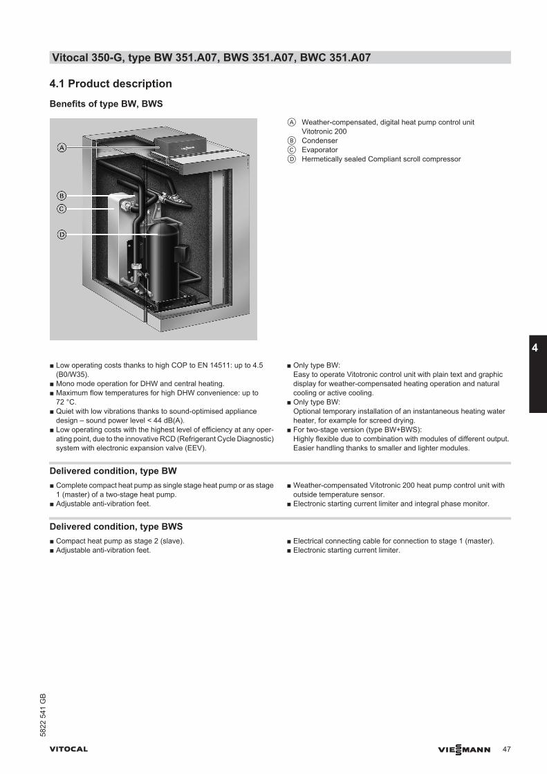
4.1 Product description
Benefits of type BW, BWS
A Weather-compensated, digital heat pump control unitVitotronic 200
B CondenserC EvaporatorD Hermetically sealed Compliant scroll compressor
■ Low operating costs thanks to high COP to EN 14511: up to 4.5(B0/W35).
■ Mono mode operation for DHW and central heating.■ Maximum flow temperatures for high DHW convenience: up to
72 °C.■ Quiet with low vibrations thanks to sound-optimised appliance
design – sound power level < 44 dB(A).■ Low operating costs with the highest level of efficiency at any oper-
ating point, due to the innovative RCD (Refrigerant Cycle Diagnostic)system with electronic expansion valve (EEV).
■ Only type BW:Easy to operate Vitotronic control unit with plain text and graphicdisplay for weather-compensated heating operation and naturalcooling or active cooling.
■ Only type BW:Optional temporary installation of an instantaneous heating waterheater, for example for screed drying.
■ For two-stage version (type BW+BWS):Highly flexible due to combination with modules of different output.Easier handling thanks to smaller and lighter modules.
Delivered condition, type BW■ Complete compact heat pump as single stage heat pump or as stage
1 (master) of a two-stage heat pump.■ Adjustable anti-vibration feet.
■ Weather-compensated Vitotronic 200 heat pump control unit withoutside temperature sensor.
■ Electronic starting current limiter and integral phase monitor.
Delivered condition, type BWS■ Compact heat pump as stage 2 (slave).■ Adjustable anti-vibration feet.
■ Electrical connecting cable for connection to stage 1 (master).■ Electronic starting current limiter.
Vitocal 350-G, type BW 351.A07, BWS 351.A07, BWC 351.A07
VITOCAL VIESMANN 47
5822
541
GB
4
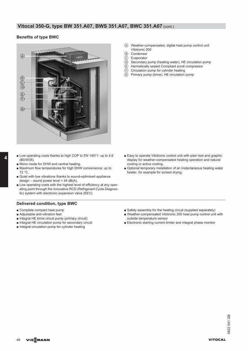
Benefits of type BWC
A Weather-compensated, digital heat pump control unitVitotronic 200
B CondenserC EvaporatorD Secondary pump (heating water), HE circulation pumpE Hermetically sealed Compliant scroll compressorF Circulation pump for cylinder heatingG Primary pump (brine), HE circulation pump
■ Low operating costs thanks to high COP to EN 14511: up to 4.6(B0/W35).
■ Mono mode for DHW and central heating.■ Maximum flow temperatures for high DHW convenience: up to
72 °C.■ Quiet with low vibrations thanks to sound-optimised appliance
design – sound power level < 44 dB(A).■ Low operating costs with the highest level of efficiency at any oper-
ating point through the innovative RCD (Refrigerant Cycle Diagnos-tic) system with electronic expansion valve (EEV).
■ Easy to operate Vitotronic control unit with plain text and graphicdisplay for weather-compensated heating operation and naturalcooling or active cooling.
■ Optional temporary installation of an instantaneous heating waterheater, for example for screed drying.
Delivered condition, type BWC■ Complete compact heat pump■ Adjustable anti-vibration feet■ Integral HE brine circuit pump (primary circuit)■ Integral HE circulation pump for secondary circuit■ Integral circulation pump for cylinder heating
■ Safety assembly for the heating circuit (supplied separately)■ Weather-compensated Vitotronic 200 heat pump control unit with
outside temperature sensor■ Electronic starting current limiter and integral phase monitor
Vitocal 350-G, type BW 351.A07, BWS 351.A07, BWC 351.A07 (cont.)
48 VIESMANN VITOCAL
4
5822
541
GB
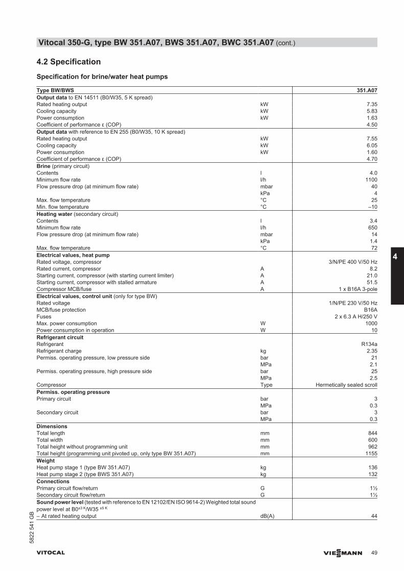
4.2 Specification
Specification for brine/water heat pumps
Type BW/BWS 351.A07Output data to EN 14511 (B0/W35, 5 K spread) Rated heating output kW 7.35Cooling capacity kW 5.83Power consumption kW 1.63Coefficient of performance ε (COP) 4.50Output data with reference to EN 255 (B0/W35, 10 K spread) Rated heating output kW 7.55Cooling capacity kW 6.05Power consumption kW 1.60Coefficient of performance ε (COP) 4.70Brine (primary circuit) Contents l 4.0Minimum flow rate l/h 1100Flow pressure drop (at minimum flow rate) mbar 40 kPa 4Max. flow temperature °C 25Min. flow temperature °C –10Heating water (secondary circuit) Contents l 3.4Minimum flow rate l/h 650Flow pressure drop (at minimum flow rate) mbar 14 kPa 1.4Max. flow temperature °C 72Electrical values, heat pump Rated voltage, compressor 3/N/PE 400 V/50 HzRated current, compressor A 8.2Starting current, compressor (with starting current limiter) A 21.0Starting current, compressor with stalled armature A 51.5Compressor MCB/fuse A 1 x B16A 3-poleElectrical values, control unit (only for type BW) Rated voltage 1/N/PE 230 V/50 HzMCB/fuse protection B16AFuses 2 x 6.3 A H/250 VMax. power consumption W 1000Power consumption in operation W 10Refrigerant circuit Refrigerant R134aRefrigerant charge kg 2.35Permiss. operating pressure, low pressure side bar 21 MPa 2.1Permiss. operating pressure, high pressure side bar 25 MPa 2.5Compressor Type Hermetically sealed scrollPermiss. operating pressure Primary circuit bar 3 MPa 0.3Secondary circuit bar 3 MPa 0.3Dimensions Total length mm 844Total width mm 600Total height without programming unit mm 962Total height (programming unit pivoted up, only type BW 351.A07) mm 1155Weight Heat pump stage 1 (type BW 351.A07) kg 136Heat pump stage 2 (type BWS 351.A07) kg 132Connections Primary circuit flow/return G 1½Secondary circuit flow/return G 1½Sound power level (tested with reference to EN 12102/EN ISO 9614-2) Weighted total soundpower level at B0±3 K/W35 ±5 K
– At rated heating output dB(A) 44
Vitocal 350-G, type BW 351.A07, BWS 351.A07, BWC 351.A07 (cont.)
VITOCAL VIESMANN 49
5822
541
GB
4
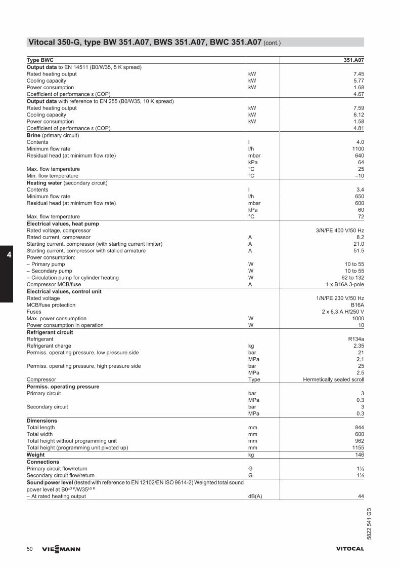
Type BWC 351.A07Output data to EN 14511 (B0/W35, 5 K spread) Rated heating output kW 7.45Cooling capacity kW 5.77Power consumption kW 1.68Coefficient of performance ε (COP) 4.67Output data with reference to EN 255 (B0/W35, 10 K spread) Rated heating output kW 7.59Cooling capacity kW 6.12Power consumption kW 1.58Coefficient of performance ε (COP) 4.81Brine (primary circuit) Contents l 4.0Minimum flow rate l/h 1100Residual head (at minimum flow rate) mbar 640 kPa 64Max. flow temperature °C 25Min. flow temperature °C –10Heating water (secondary circuit) Contents l 3.4Minimum flow rate l/h 650Residual head (at minimum flow rate) mbar 600 kPa 60Max. flow temperature °C 72Electrical values, heat pump Rated voltage, compressor 3/N/PE 400 V/50 HzRated current, compressor A 8.2Starting current, compressor (with starting current limiter) A 21.0Starting current, compressor with stalled armature A 51.5Power consumption: – Primary pump W 10 to 55– Secondary pump W 10 to 55– Circulation pump for cylinder heating W 62 to 132Compressor MCB/fuse A 1 x B16A 3-poleElectrical values, control unit Rated voltage 1/N/PE 230 V/50 HzMCB/fuse protection B16AFuses 2 x 6.3 A H/250 VMax. power consumption W 1000Power consumption in operation W 10Refrigerant circuit Refrigerant R134aRefrigerant charge kg 2.35Permiss. operating pressure, low pressure side bar 21 MPa 2.1Permiss. operating pressure, high pressure side bar 25 MPa 2.5Compressor Type Hermetically sealed scrollPermiss. operating pressure Primary circuit bar 3 MPa 0.3Secondary circuit bar 3 MPa 0.3Dimensions Total length mm 844Total width mm 600Total height without programming unit mm 962Total height (programming unit pivoted up) mm 1155Weight kg 146Connections Primary circuit flow/return G 1½Secondary circuit flow/return G 1½Sound power level (tested with reference to EN 12102/EN ISO 9614-2) Weighted total soundpower level at B0±3 K/W35±5 K
– At rated heating output dB(A) 44
Vitocal 350-G, type BW 351.A07, BWS 351.A07, BWC 351.A07 (cont.)
50 VIESMANN VITOCAL
4
5822
541
GB
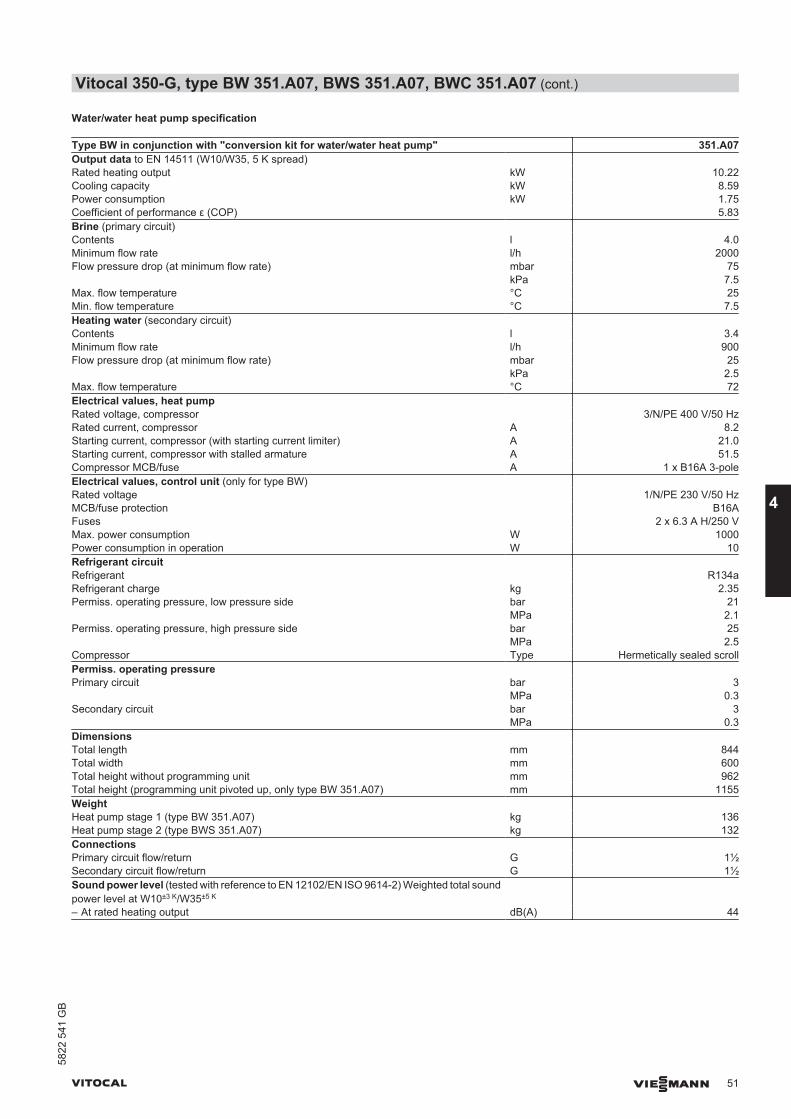
Water/water heat pump specification
Type BW in conjunction with "conversion kit for water/water heat pump" 351.A07Output data to EN 14511 (W10/W35, 5 K spread) Rated heating output kW 10.22Cooling capacity kW 8.59Power consumption kW 1.75Coefficient of performance ε (COP) 5.83Brine (primary circuit) Contents l 4.0Minimum flow rate l/h 2000Flow pressure drop (at minimum flow rate) mbar 75 kPa 7.5Max. flow temperature °C 25Min. flow temperature °C 7.5Heating water (secondary circuit) Contents l 3.4Minimum flow rate l/h 900Flow pressure drop (at minimum flow rate) mbar 25 kPa 2.5Max. flow temperature °C 72Electrical values, heat pump Rated voltage, compressor 3/N/PE 400 V/50 HzRated current, compressor A 8.2Starting current, compressor (with starting current limiter) A 21.0Starting current, compressor with stalled armature A 51.5Compressor MCB/fuse A 1 x B16A 3-poleElectrical values, control unit (only for type BW) Rated voltage 1/N/PE 230 V/50 HzMCB/fuse protection B16AFuses 2 x 6.3 A H/250 VMax. power consumption W 1000Power consumption in operation W 10Refrigerant circuit Refrigerant R134aRefrigerant charge kg 2.35Permiss. operating pressure, low pressure side bar 21 MPa 2.1Permiss. operating pressure, high pressure side bar 25 MPa 2.5Compressor Type Hermetically sealed scrollPermiss. operating pressure Primary circuit bar 3 MPa 0.3Secondary circuit bar 3 MPa 0.3Dimensions Total length mm 844Total width mm 600Total height without programming unit mm 962Total height (programming unit pivoted up, only type BW 351.A07) mm 1155Weight Heat pump stage 1 (type BW 351.A07) kg 136Heat pump stage 2 (type BWS 351.A07) kg 132Connections Primary circuit flow/return G 1½Secondary circuit flow/return G 1½Sound power level (tested with reference to EN 12102/EN ISO 9614-2) Weighted total soundpower level at W10±3 K/W35±5 K
– At rated heating output dB(A) 44
Vitocal 350-G, type BW 351.A07, BWS 351.A07, BWC 351.A07 (cont.)
VITOCAL VIESMANN 51
5822
541
GB
4
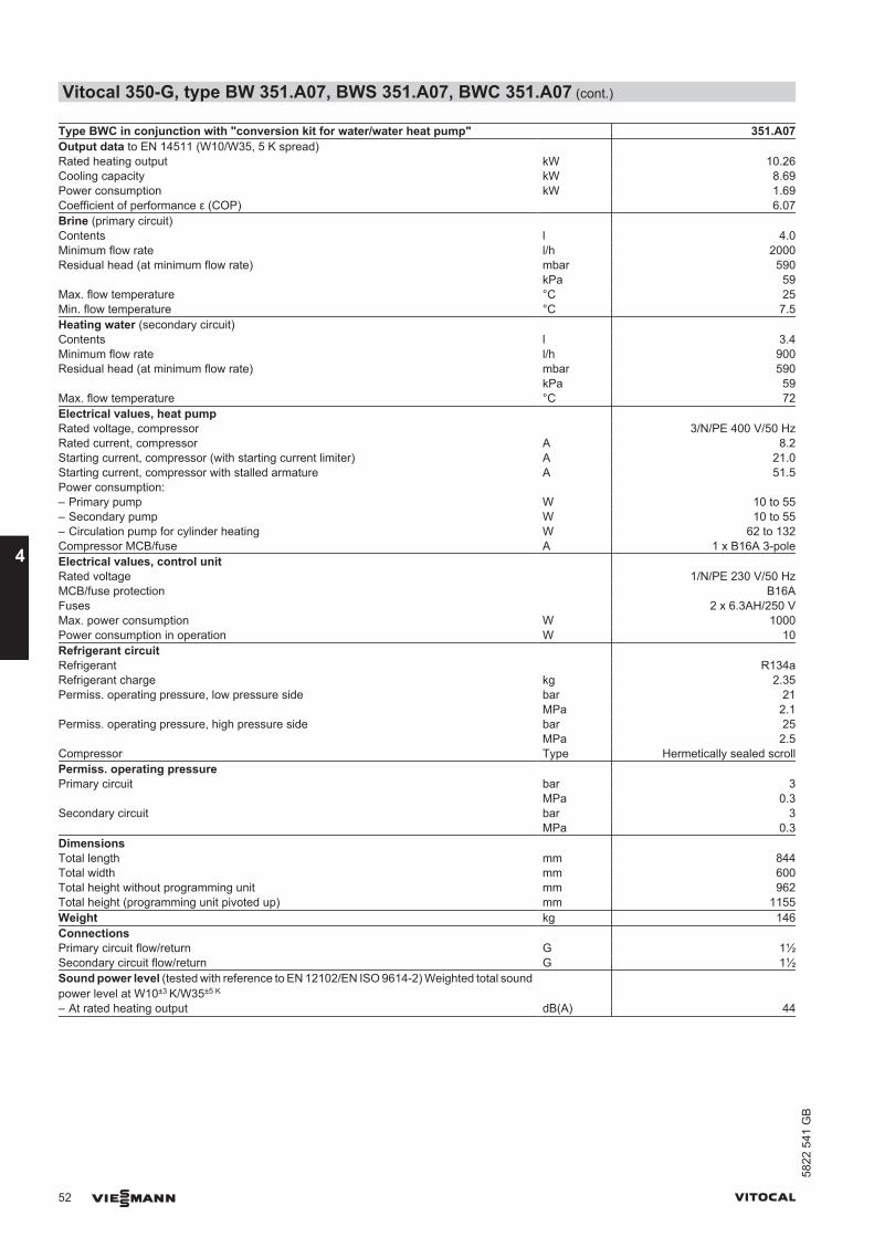
Type BWC in conjunction with "conversion kit for water/water heat pump" 351.A07Output data to EN 14511 (W10/W35, 5 K spread) Rated heating output kW 10.26Cooling capacity kW 8.69Power consumption kW 1.69Coefficient of performance ε (COP) 6.07Brine (primary circuit) Contents l 4.0Minimum flow rate l/h 2000Residual head (at minimum flow rate) mbar 590 kPa 59Max. flow temperature °C 25Min. flow temperature °C 7.5Heating water (secondary circuit) Contents l 3.4Minimum flow rate l/h 900Residual head (at minimum flow rate) mbar 590 kPa 59Max. flow temperature °C 72Electrical values, heat pump Rated voltage, compressor 3/N/PE 400 V/50 HzRated current, compressor A 8.2Starting current, compressor (with starting current limiter) A 21.0Starting current, compressor with stalled armature A 51.5Power consumption: – Primary pump W 10 to 55– Secondary pump W 10 to 55– Circulation pump for cylinder heating W 62 to 132Compressor MCB/fuse A 1 x B16A 3-poleElectrical values, control unit Rated voltage 1/N/PE 230 V/50 HzMCB/fuse protection B16AFuses 2 x 6.3AH/250 VMax. power consumption W 1000Power consumption in operation W 10Refrigerant circuit Refrigerant R134aRefrigerant charge kg 2.35Permiss. operating pressure, low pressure side bar 21 MPa 2.1Permiss. operating pressure, high pressure side bar 25 MPa 2.5Compressor Type Hermetically sealed scrollPermiss. operating pressure Primary circuit bar 3 MPa 0.3Secondary circuit bar 3 MPa 0.3Dimensions Total length mm 844Total width mm 600Total height without programming unit mm 962Total height (programming unit pivoted up) mm 1155Weight kg 146Connections Primary circuit flow/return G 1½Secondary circuit flow/return G 1½Sound power level (tested with reference to EN 12102/EN ISO 9614-2) Weighted total soundpower level at W10±3 K/W35±5 K
– At rated heating output dB(A) 44
Vitocal 350-G, type BW 351.A07, BWS 351.A07, BWC 351.A07 (cont.)
52 VIESMANN VITOCAL
4
5822
541
GB
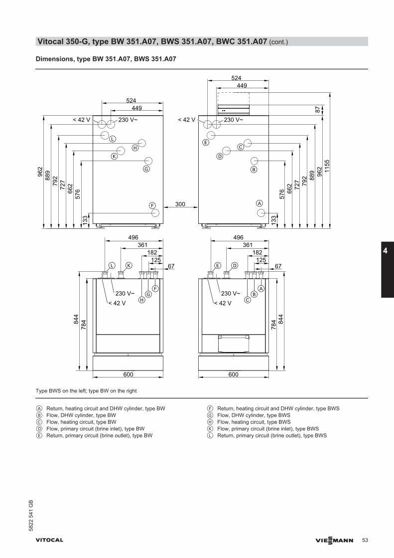
Dimensions, type BW 351.A07, BWS 351.A07
133
57666
272779
288996
2
133
576 66
2 727 79
2 889 96
2 1155
87
67125
182361
496
67125
182361
496
449524
449524
600 600
300
230 V~< 42 V
A
78484
4
230 V~< 42 V
B
C
D
E
F
G
H
K
L
230 V~< 42 V
230 V~< 42 V
AB
C
E D
FG
H
L K78
4 844
Type BWS on the left; type BW on the right
A Return, heating circuit and DHW cylinder, type BWB Flow, DHW cylinder, type BWC Flow, heating circuit, type BWD Flow, primary circuit (brine inlet), type BWE Return, primary circuit (brine outlet), type BW
F Return, heating circuit and DHW cylinder, type BWSG Flow, DHW cylinder, type BWSH Flow, heating circuit, type BWSK Flow, primary circuit (brine inlet), type BWSL Return, primary circuit (brine outlet), type BWS
Vitocal 350-G, type BW 351.A07, BWS 351.A07, BWC 351.A07 (cont.)
VITOCAL VIESMANN 53
5822
541
GB
4

Dimensions, type BWC 351.A07
133
576 66
2 727 79
2 889 96
2 1155
87
67125
182361
496
449524
600
A
230 V~< 42 V
B
C
D
E
230 V~< 42 V
AB
C
E D
784 84
4
A Return, heating circuit and DHW cylinderB DHW cylinder flowC Heating circuit flow
D Primary circuit flow (brine inlet)E Primary circuit return (brine outlet)
Vitocal 350-G, type BW 351.A07, BWS 351.A07, BWC 351.A07 (cont.)
54 VIESMANN VITOCAL
4
5822
541
GB
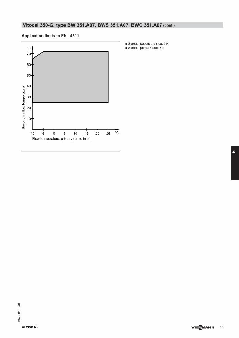
Application limits to EN 14511
Seco
ndar
y flo
w te
mpe
ratu
re
Flow temperature, primary (brine inlet)-5 0 5
°C
°C10 15 20 25-10
10
20
30
40
50
60
70
■ Spread, secondary side: 5 K■ Spread, primary side: 3 K
Vitocal 350-G, type BW 351.A07, BWS 351.A07, BWC 351.A07 (cont.)
VITOCAL VIESMANN 55
5822
541
GB
4

Curves, type BW, BWS
Type BW 351.A07, BWS 351.A07
0
2
-10 -5 0 5 10 15 20 25
-10 -5 0 5 10 15 20 250
2
4
6
Water / brineinlet temperature in °C
4
2-10 -5 0 5 10 15 20 25
4
6
8
10
12
14
2-10 -5 0 5 10 15 20 25
4
6
8
10
12
Coe
ffici
ent o
f per
f.C
OP
Ref
riger
atio
n ca
paci
ty in
kW
Pow
erco
nsum
ptio
n in
kW
Hea
ting
outp
ut in
kW
35 °C45 °C55 °C65 °C
35 °C45 °C55 °C65 °C72 °C
72 °C
35 °C
45 °C
55 °C
65 °C72 °C
35 °C
45 °C55 °C65 °C72 °C
Note■ COP calculated with reference to EN 14511.■ Performance characteristics apply to new appliances with clean
plate heat exchangers.
10
0
30
20
40
0 1 2 3kPa
Flow rate in m³/h4 5
A B100
0
300
200
400
mba
rPr
essu
re d
rop
A Secondary circuitB Primary circuit
Output dataOperatingpoint
W °C 35B °C -5 0 5 10 15
Heating output kW 6.30 7.35 8.66 9.96 10.49Cooling capacity kW 4.81 5.83 7.10 8.38 8.88Power consumption kW 1.60 1.63 1.67 1.70 1.74Coefficient of per-formance ε (COP)
3.93 4.50 5.18 5.85 6.05
Operatingpoint
W °C 45B °C -5 0 5 10 15
Heating output kW 6.04 7.07 8.39 9.71 11.03Cooling capacity kW 4.28 5.25 6.53 7.82 9.10Power consumption kW 1.89 1.95 2.00 2.04 2.08Coefficient of per-formance ε (COP)
3.18 3.62 4.18 4.75 5.31
Operatingpoint
W °C 55B °C -5 0 5 10 15
Heating output kW 5.79 6.76 8.04 9.33 10.61Cooling capacity kW 3.73 4.61 5.83 7.05 8.27Power consumption kW 2.22 2.31 2.38 2.45 2.52Coefficient of per-formance ε (COP)
2.59 2.93 3.36 3.79 4.22
Operatingpoint
W °C 65B °C -5 0 5 10 15
Heating output kW 5.60 6.50 7.70 8.90 10.10Cooling capacity kW 3.16 3.96 5.08 6.19 7.30Power consumption kW 2.62 2.72 2.82 2.91 3.01Coefficient of per-formance ε (COP)
2.13 2.39 2.71 3.03 3.36
Operatingpoint
W °C 72B °C -5 0 5 10 15
Heating output kW 5.38 6.31 7.43 8.56 9.69Cooling capacity kW 2.64 3.46 4.48 5.51 6.53Power consumption kW 2.95 3.06 3.17 3.28 3.40Coefficient of per-formance ε (COP)
1.82 2.06 2.33 2.59 2.85
Vitocal 350-G, type BW 351.A07, BWS 351.A07, BWC 351.A07 (cont.)
56 VIESMANN VITOCAL
4
5822
541
GB
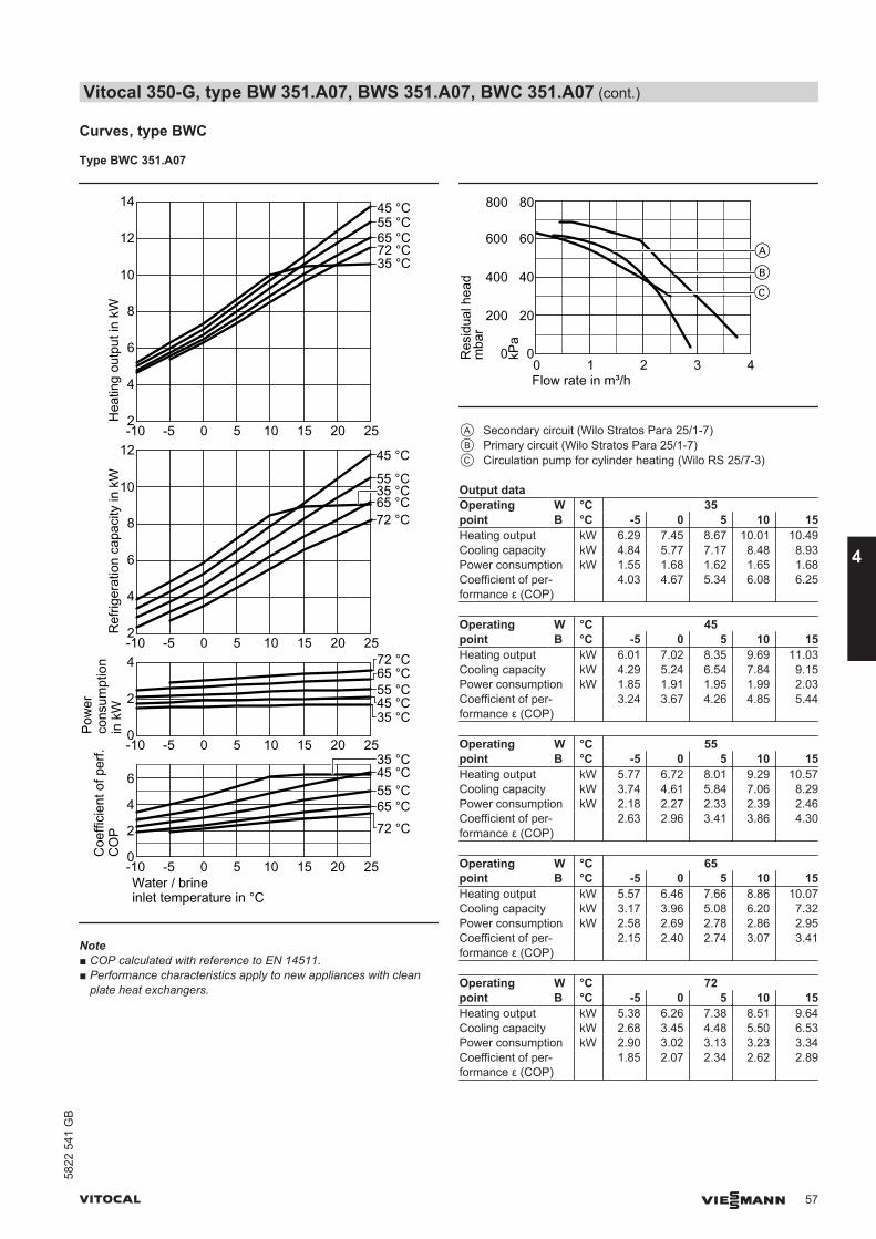
Curves, type BWC
Type BWC 351.A07
0
2
-10 -5 0 5 10 15 20 25
-10 -5 0 5 10 15 20 250
2
4
6
Water / brineinlet temperature in °C
4
2-10 -5 0 5 10 15 20 25
12
4
6
8
10
2-10 -5 0 5 10 15 20 25
12
14
4
6
8
10
Coe
ffici
ent o
f per
f.C
OP
Ref
riger
atio
n ca
paci
ty in
kW
Pow
erco
nsum
ptio
n in
kW
Hea
ting
outp
ut in
kW
35 °C45 °C55 °C65 °C
35 °C45 °C55 °C65 °C72 °C
72 °C
35 °C
45 °C
55 °C
65 °C72 °C
35 °C
45 °C55 °C65 °C72 °C
Note■ COP calculated with reference to EN 14511.■ Performance characteristics apply to new appliances with clean
plate heat exchangers.
200
0
600
400
0 1 2 3
Res
idua
l hea
d
Flow rate in m³/h4
A
B
800
C
mba
r
20
0
60
40
80
kPa
A Secondary circuit (Wilo Stratos Para 25/1-7)B Primary circuit (Wilo Stratos Para 25/1-7)C Circulation pump for cylinder heating (Wilo RS 25/7-3)
Output dataOperatingpoint
W °C 35B °C -5 0 5 10 15
Heating output kW 6.29 7.45 8.67 10.01 10.49Cooling capacity kW 4.84 5.77 7.17 8.48 8.93Power consumption kW 1.55 1.68 1.62 1.65 1.68Coefficient of per-formance ε (COP)
4.03 4.67 5.34 6.08 6.25
Operatingpoint
W °C 45B °C -5 0 5 10 15
Heating output kW 6.01 7.02 8.35 9.69 11.03Cooling capacity kW 4.29 5.24 6.54 7.84 9.15Power consumption kW 1.85 1.91 1.95 1.99 2.03Coefficient of per-formance ε (COP)
3.24 3.67 4.26 4.85 5.44
Operatingpoint
W °C 55B °C -5 0 5 10 15
Heating output kW 5.77 6.72 8.01 9.29 10.57Cooling capacity kW 3.74 4.61 5.84 7.06 8.29Power consumption kW 2.18 2.27 2.33 2.39 2.46Coefficient of per-formance ε (COP)
2.63 2.96 3.41 3.86 4.30
Operatingpoint
W °C 65B °C -5 0 5 10 15
Heating output kW 5.57 6.46 7.66 8.86 10.07Cooling capacity kW 3.17 3.96 5.08 6.20 7.32Power consumption kW 2.58 2.69 2.78 2.86 2.95Coefficient of per-formance ε (COP)
2.15 2.40 2.74 3.07 3.41
Operatingpoint
W °C 72B °C -5 0 5 10 15
Heating output kW 5.38 6.26 7.38 8.51 9.64Cooling capacity kW 2.68 3.45 4.48 5.50 6.53Power consumption kW 2.90 3.02 3.13 3.23 3.34Coefficient of per-formance ε (COP)
1.85 2.07 2.34 2.62 2.89
Vitocal 350-G, type BW 351.A07, BWS 351.A07, BWC 351.A07 (cont.)
VITOCAL VIESMANN 57
5822
541
GB
4
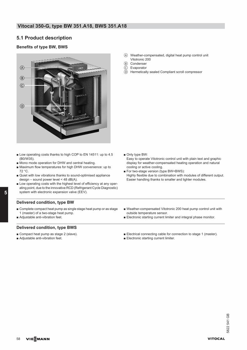
5.1 Product description
Benefits of type BW, BWS
A Weather-compensated, digital heat pump control unitVitotronic 200
B CondenserC EvaporatorD Hermetically sealed Compliant scroll compressor
■ Low operating costs thanks to high COP to EN 14511: up to 4.5(B0/W35).
■ Mono mode operation for DHW and central heating.■ Maximum flow temperatures for high DHW convenience: up to
72 °C.■ Quiet with low vibrations thanks to sound-optimised appliance
design – sound power level < 48 dB(A).■ Low operating costs with the highest level of efficiency at any oper-
ating point, due to the innovative RCD (Refrigerant Cycle Diagnostic)system with electronic expansion valve (EEV).
■ Only type BW:Easy to operate Vitotronic control unit with plain text and graphicdisplay for weather-compensated heating operation and naturalcooling or active cooling.
■ For two-stage version (type BW+BWS):Highly flexible due to combination with modules of different output.Easier handling thanks to smaller and lighter modules.
Delivered condition, type BW■ Complete compact heat pump as single stage heat pump or as stage
1 (master) of a two-stage heat pump.■ Adjustable anti-vibration feet.
■ Weather-compensated Vitotronic 200 heat pump control unit withoutside temperature sensor.
■ Electronic starting current limiter and integral phase monitor.
Delivered condition, type BWS■ Compact heat pump as stage 2 (slave).■ Adjustable anti-vibration feet.
■ Electrical connecting cable for connection to stage 1 (master).■ Electronic starting current limiter.
Vitocal 350-G, type BW 351.A18, BWS 351.A18
58 VIESMANN VITOCAL
5
5822
541
GB
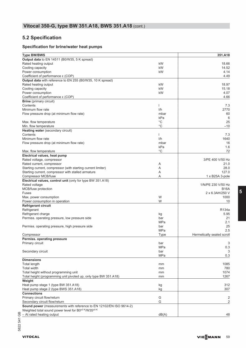
5.2 Specification
Specification for brine/water heat pumps
Type BW/BWS 351.A18Output data to EN 14511 (B0/W35, 5 K spread) Rated heating output kW 18.66Cooling capacity kW 14.52Power consumption kW 4.14Coefficient of performance ε (COP) 4.49Output data with reference to EN 255 (B0/W35, 10 K spread) Rated heating output kW 18.97Cooling capacity kW 15.18Power consumption kW 4.07Coefficient of performance ε (COP) 4.66Brine (primary circuit) Contents l 7.3Minimum flow rate l/h 2770Flow pressure drop (at minimum flow rate) mbar 60
kPa 6Max. flow temperature °C 25Min. flow temperature °C –10Heating water (secondary circuit) Contents l 7.3Minimum flow rate l/h 1640Flow pressure drop (at minimum flow rate) mbar 16
kPa 1.6Max. flow temperature °C 72Electrical values, heat pump Rated voltage, compressor 3/PE 400 V/50 HzRated current, compressor A 21.0Starting current, compressor (with starting current limiter) A 28.0Starting current, compressor with stalled armature A 127.0Compressor MCB/fuse A 1 x B25A 3-poleElectrical values, control unit (only for type BW 351.A18) Rated voltage 1/N/PE 230 V/50 HzMCB/fuse protection B16AFuses 2 x 6.3AH/250 VMax. power consumption W 1000Power consumption in operation W 10Refrigerant circuit Refrigerant R134aRefrigerant charge kg 5.95Permiss. operating pressure, low pressure side bar 21
MPa 2.1Permiss. operating pressure, high pressure side bar 25
MPa 2.5Compressor Type Hermetically sealed scrollPermiss. operating pressure Primary circuit bar 3
MPa 0.3Secondary circuit bar 3
MPa 0.3Dimensions Total length mm 1085Total width mm 780Total height without programming unit mm 1074Total height (programming unit pivoted up, only type BW 351.A18) mm 1267Weight Heat pump stage 1 (type BW 351.A18) kg 312Heat pump stage 2 (type BWS 351.A18) kg 307Connections Primary circuit flow/return G 2Secondary circuit flow/return G 2Sound power (measurements with reference to EN 12102/EN ISO 9614-2)Weighted total sound power level for B0±3 K/W35±5 K
– At rated heating output dB(A) 48
Vitocal 350-G, type BW 351.A18, BWS 351.A18 (cont.)
VITOCAL VIESMANN 59
5822
541
GB
5
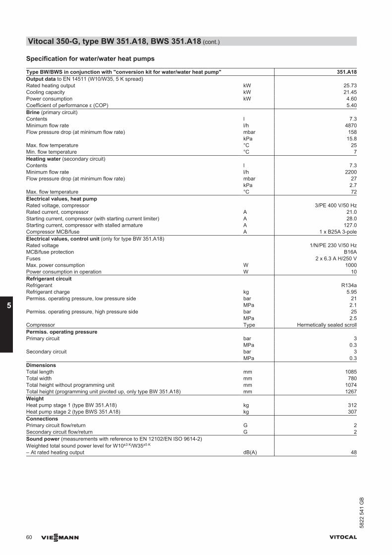
Specification for water/water heat pumps
Type BW/BWS in conjunction with "conversion kit for water/water heat pump" 351.A18Output data to EN 14511 (W10/W35, 5 K spread) Rated heating output kW 25.73Cooling capacity kW 21.45Power consumption kW 4.60Coefficient of performance ε (COP) 5.40Brine (primary circuit) Contents l 7.3Minimum flow rate l/h 4870Flow pressure drop (at minimum flow rate) mbar 158
kPa 15.8Max. flow temperature °C 25Min. flow temperature °C 7Heating water (secondary circuit) Contents l 7.3Minimum flow rate l/h 2200Flow pressure drop (at minimum flow rate) mbar 27
kPa 2.7Max. flow temperature °C 72Electrical values, heat pump Rated voltage, compressor 3/PE 400 V/50 HzRated current, compressor A 21.0Starting current, compressor (with starting current limiter) A 28.0Starting current, compressor with stalled armature A 127.0Compressor MCB/fuse A 1 x B25A 3-poleElectrical values, control unit (only for type BW 351.A18) Rated voltage 1/N/PE 230 V/50 HzMCB/fuse protection B16AFuses 2 x 6.3 A H/250 VMax. power consumption W 1000Power consumption in operation W 10Refrigerant circuit Refrigerant R134aRefrigerant charge kg 5.95Permiss. operating pressure, low pressure side bar 21
MPa 2.1Permiss. operating pressure, high pressure side bar 25
MPa 2.5Compressor Type Hermetically sealed scrollPermiss. operating pressure Primary circuit bar 3
MPa 0.3Secondary circuit bar 3
MPa 0.3Dimensions Total length mm 1085Total width mm 780Total height without programming unit mm 1074Total height (programming unit pivoted up, only type BW 351.A18) mm 1267Weight Heat pump stage 1 (type BW 351.A18) kg 312Heat pump stage 2 (type BWS 351.A18) kg 307Connections Primary circuit flow/return G 2Secondary circuit flow/return G 2Sound power (measurements with reference to EN 12102/EN ISO 9614-2)Weighted total sound power level for W10±3 K/W35±5 K
– At rated heating output dB(A) 48
Vitocal 350-G, type BW 351.A18, BWS 351.A18 (cont.)
60 VIESMANN VITOCAL
5
5822
541
GB
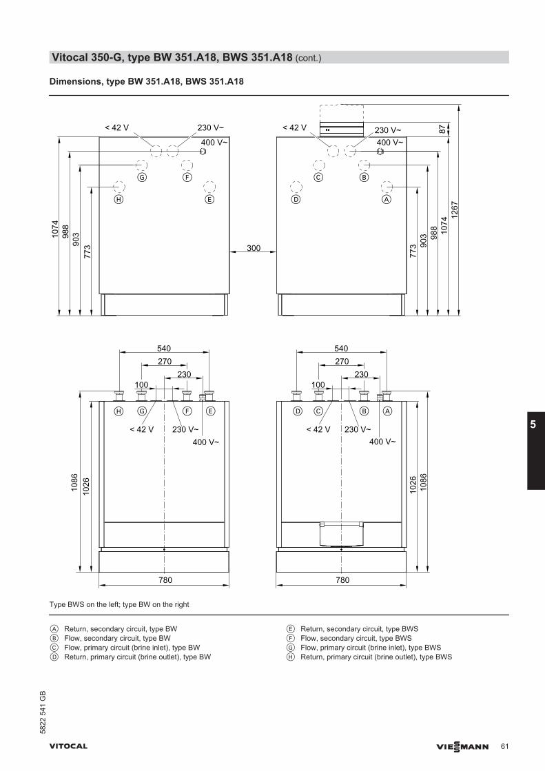
Dimensions, type BW 351.A18, BWS 351.A18
87
780 780
230
540270
1026
230
540270
773
773 300
400 V~
230 V~< 42 V
400 V~230 V~< 42 V
90398
810
74
1086
100
400 V~230 V~< 42 V
903 98
8 1074
1267
100
1026
1086
400 V~230 V~< 42 V
A
BC
DE
FG
H
BCFGH E D A
Type BWS on the left; type BW on the right
A Return, secondary circuit, type BWB Flow, secondary circuit, type BWC Flow, primary circuit (brine inlet), type BWD Return, primary circuit (brine outlet), type BW
E Return, secondary circuit, type BWSF Flow, secondary circuit, type BWSG Flow, primary circuit (brine inlet), type BWSH Return, primary circuit (brine outlet), type BWS
Vitocal 350-G, type BW 351.A18, BWS 351.A18 (cont.)
VITOCAL VIESMANN 61
5822
541
GB
5
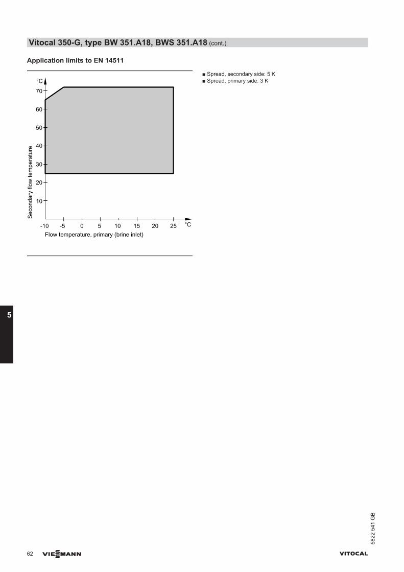
Application limits to EN 14511
Seco
ndar
y flo
w te
mpe
ratu
re
Flow temperature, primary (brine inlet)-5 0 5
°C
°C10 15 20 25-10
10
20
30
40
50
60
70
■ Spread, secondary side: 5 K■ Spread, primary side: 3 K
Vitocal 350-G, type BW 351.A18, BWS 351.A18 (cont.)
62 VIESMANN VITOCAL
5
5822
541
GB
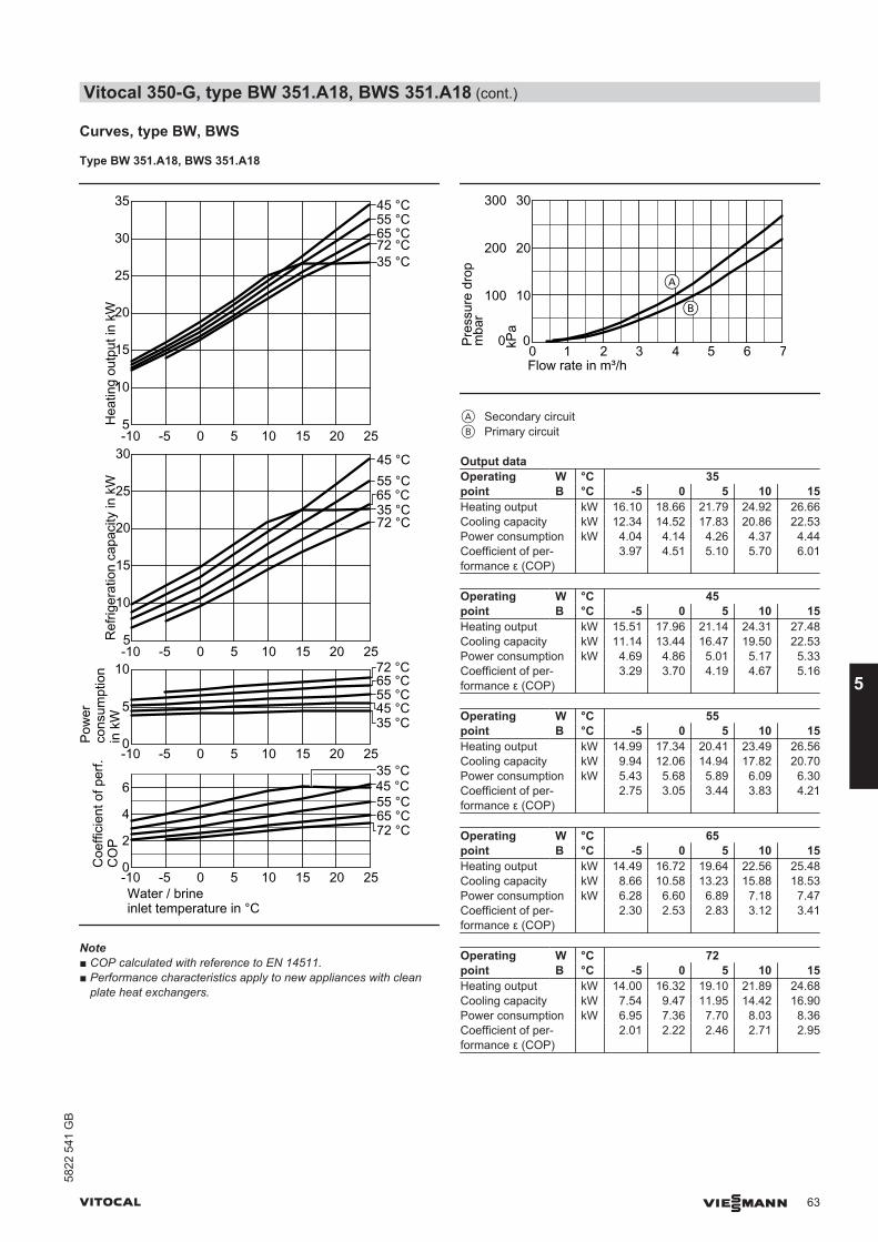
Curves, type BW, BWS
Type BW 351.A18, BWS 351.A18
0
5
-10 -5 0 5 10 15 20 25
-10 -5 0 5 10 15 20 250
2
4
6
Water / brineinlet temperature in °C
10
Coe
ffici
ent o
f per
f.C
OP
Ref
riger
atio
n ca
paci
ty in
kW
Pow
erco
nsum
ptio
n in
kW
Hea
ting
outp
ut in
kW
35 °C45 °C55 °C65 °C
35 °C45 °C55 °C65 °C72 °C
72 °C
35 °C
45 °C55 °C65 °C
72 °C
35 °C
45 °C55 °C65 °C72 °C
5-10 -5 0 5 10 15 20 25
25
30
35
10
15
20
5-10 -5 0 5 10 15 20 25
25
30
10
15
20
Note■ COP calculated with reference to EN 14511.■ Performance characteristics apply to new appliances with clean
plate heat exchangers.
10
0
30
20
0 1 2 3Flow rate in m³/h
4 5 6 7kPa
100
0
300
200
Pres
sure
dro
pm
bar
A
B
A Secondary circuitB Primary circuit
Output dataOperatingpoint
W °C 35B °C -5 0 5 10 15
Heating output kW 16.10 18.66 21.79 24.92 26.66Cooling capacity kW 12.34 14.52 17.83 20.86 22.53Power consumption kW 4.04 4.14 4.26 4.37 4.44Coefficient of per-formance ε (COP)
3.97 4.51 5.10 5.70 6.01
Operatingpoint
W °C 45B °C -5 0 5 10 15
Heating output kW 15.51 17.96 21.14 24.31 27.48Cooling capacity kW 11.14 13.44 16.47 19.50 22.53Power consumption kW 4.69 4.86 5.01 5.17 5.33Coefficient of per-formance ε (COP)
3.29 3.70 4.19 4.67 5.16
Operatingpoint
W °C 55B °C -5 0 5 10 15
Heating output kW 14.99 17.34 20.41 23.49 26.56Cooling capacity kW 9.94 12.06 14.94 17.82 20.70Power consumption kW 5.43 5.68 5.89 6.09 6.30Coefficient of per-formance ε (COP)
2.75 3.05 3.44 3.83 4.21
Operatingpoint
W °C 65B °C -5 0 5 10 15
Heating output kW 14.49 16.72 19.64 22.56 25.48Cooling capacity kW 8.66 10.58 13.23 15.88 18.53Power consumption kW 6.28 6.60 6.89 7.18 7.47Coefficient of per-formance ε (COP)
2.30 2.53 2.83 3.12 3.41
Operatingpoint
W °C 72B °C -5 0 5 10 15
Heating output kW 14.00 16.32 19.10 21.89 24.68Cooling capacity kW 7.54 9.47 11.95 14.42 16.90Power consumption kW 6.95 7.36 7.70 8.03 8.36Coefficient of per-formance ε (COP)
2.01 2.22 2.46 2.71 2.95
Vitocal 350-G, type BW 351.A18, BWS 351.A18 (cont.)
VITOCAL VIESMANN 63
5822
541
GB
5
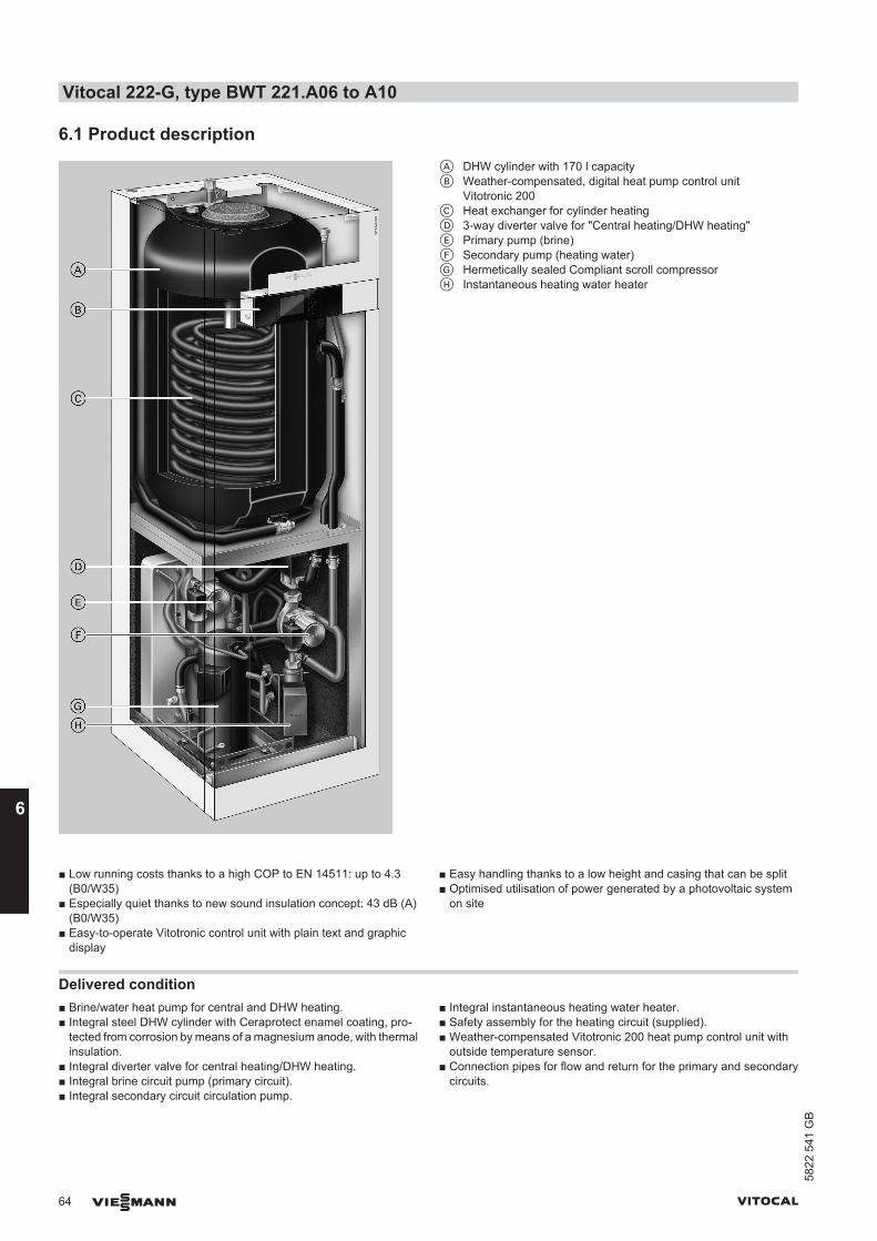
6.1 Product descriptionA DHW cylinder with 170 l capacityB Weather-compensated, digital heat pump control unit
Vitotronic 200C Heat exchanger for cylinder heatingD 3-way diverter valve for "Central heating/DHW heating"E Primary pump (brine)F Secondary pump (heating water)G Hermetically sealed Compliant scroll compressorH Instantaneous heating water heater
■ Low running costs thanks to a high COP to EN 14511: up to 4.3(B0/W35)
■ Especially quiet thanks to new sound insulation concept: 43 dB (A)(B0/W35)
■ Easy-to-operate Vitotronic control unit with plain text and graphicdisplay
■ Easy handling thanks to a low height and casing that can be split■ Optimised utilisation of power generated by a photovoltaic system
on site
Delivered condition■ Brine/water heat pump for central and DHW heating.■ Integral steel DHW cylinder with Ceraprotect enamel coating, pro-
tected from corrosion by means of a magnesium anode, with thermalinsulation.
■ Integral diverter valve for central heating/DHW heating.■ Integral brine circuit pump (primary circuit).■ Integral secondary circuit circulation pump.
■ Integral instantaneous heating water heater.■ Safety assembly for the heating circuit (supplied).■ Weather-compensated Vitotronic 200 heat pump control unit with
outside temperature sensor.■ Connection pipes for flow and return for the primary and secondary
circuits.
Vitocal 222-G, type BWT 221.A06 to A10
64 VIESMANN VITOCAL
658
22 5
41 G
B
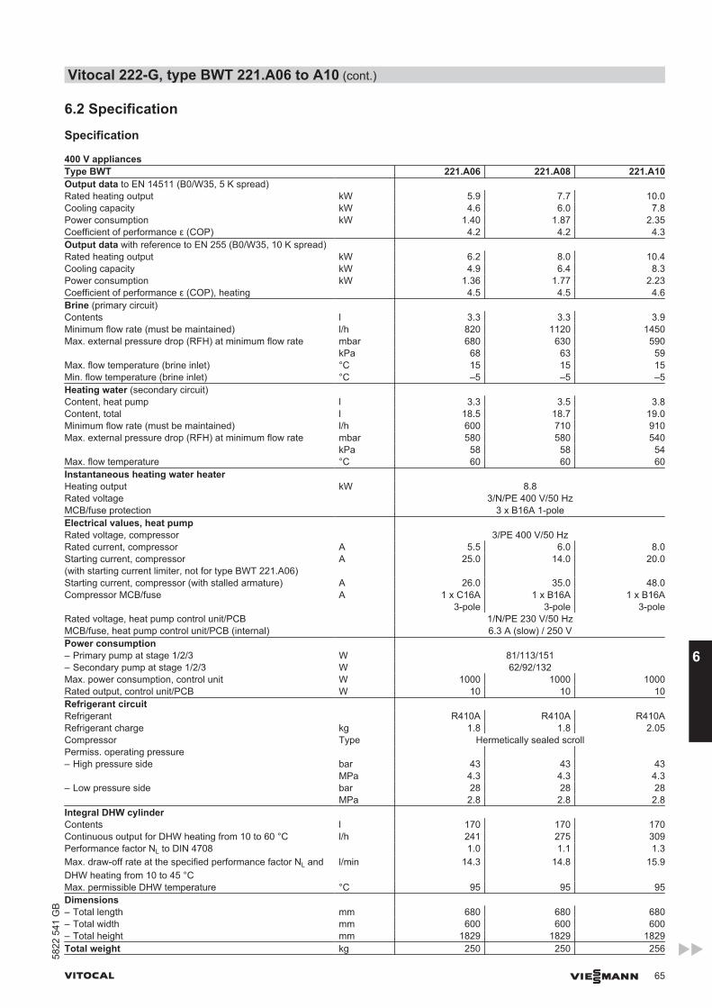
6.2 Specification
Specification
400 V appliancesType BWT 221.A06 221.A08 221.A10Output data to EN 14511 (B0/W35, 5 K spread) Rated heating output kW 5.9 7.7 10.0Cooling capacity kW 4.6 6.0 7.8Power consumption kW 1.40 1.87 2.35Coefficient of performance ε (COP) 4.2 4.2 4.3Output data with reference to EN 255 (B0/W35, 10 K spread) Rated heating output kW 6.2 8.0 10.4Cooling capacity kW 4.9 6.4 8.3Power consumption kW 1.36 1.77 2.23Coefficient of performance ε (COP), heating 4.5 4.5 4.6Brine (primary circuit) Contents l 3.3 3.3 3.9Minimum flow rate (must be maintained) l/h 820 1120 1450Max. external pressure drop (RFH) at minimum flow rate mbar 680 630 590 kPa 68 63 59Max. flow temperature (brine inlet) °C 15 15 15Min. flow temperature (brine inlet) °C –5 –5 –5Heating water (secondary circuit) Content, heat pump l 3.3 3.5 3.8Content, total l 18.5 18.7 19.0Minimum flow rate (must be maintained) l/h 600 710 910Max. external pressure drop (RFH) at minimum flow rate mbar 580 580 540 kPa 58 58 54Max. flow temperature °C 60 60 60Instantaneous heating water heater Heating output kW 8.8Rated voltage 3/N/PE 400 V/50 HzMCB/fuse protection 3 x B16A 1-poleElectrical values, heat pump Rated voltage, compressor 3/PE 400 V/50 HzRated current, compressor A 5.5 6.0 8.0Starting current, compressor(with starting current limiter, not for type BWT 221.A06)
A 25.0 14.0 20.0
Starting current, compressor (with stalled armature) A 26.0 35.0 48.0Compressor MCB/fuse A 1 x C16A
3-pole1 x B16A
3-pole1 x B16A
3-poleRated voltage, heat pump control unit/PCB 1/N/PE 230 V/50 HzMCB/fuse, heat pump control unit/PCB (internal) 6.3 A (slow) / 250 VPower consumption – Primary pump at stage 1/2/3 W 81/113/151– Secondary pump at stage 1/2/3 W 62/92/132Max. power consumption, control unit W 1000 1000 1000Rated output, control unit/PCB W 10 10 10Refrigerant circuit Refrigerant R410A R410A R410ARefrigerant charge kg 1.8 1.8 2.05Compressor Type Hermetically sealed scrollPermiss. operating pressure – High pressure side bar 43 43 43 MPa 4.3 4.3 4.3– Low pressure side bar 28 28 28 MPa 2.8 2.8 2.8Integral DHW cylinder Contents l 170 170 170Continuous output for DHW heating from 10 to 60 °C l/h 241 275 309Performance factor NL to DIN 4708 1.0 1.1 1.3Max. draw-off rate at the specified performance factor NL andDHW heating from 10 to 45 °C
l/min 14.3 14.8 15.9
Max. permissible DHW temperature °C 95 95 95Dimensions – Total length mm 680 680 680– Total width mm 600 600 600– Total height mm 1829 1829 1829Total weight kg 250 250 256
Vitocal 222-G, type BWT 221.A06 to A10 (cont.)
VITOCAL VIESMANN 65
5822
541
GB
6
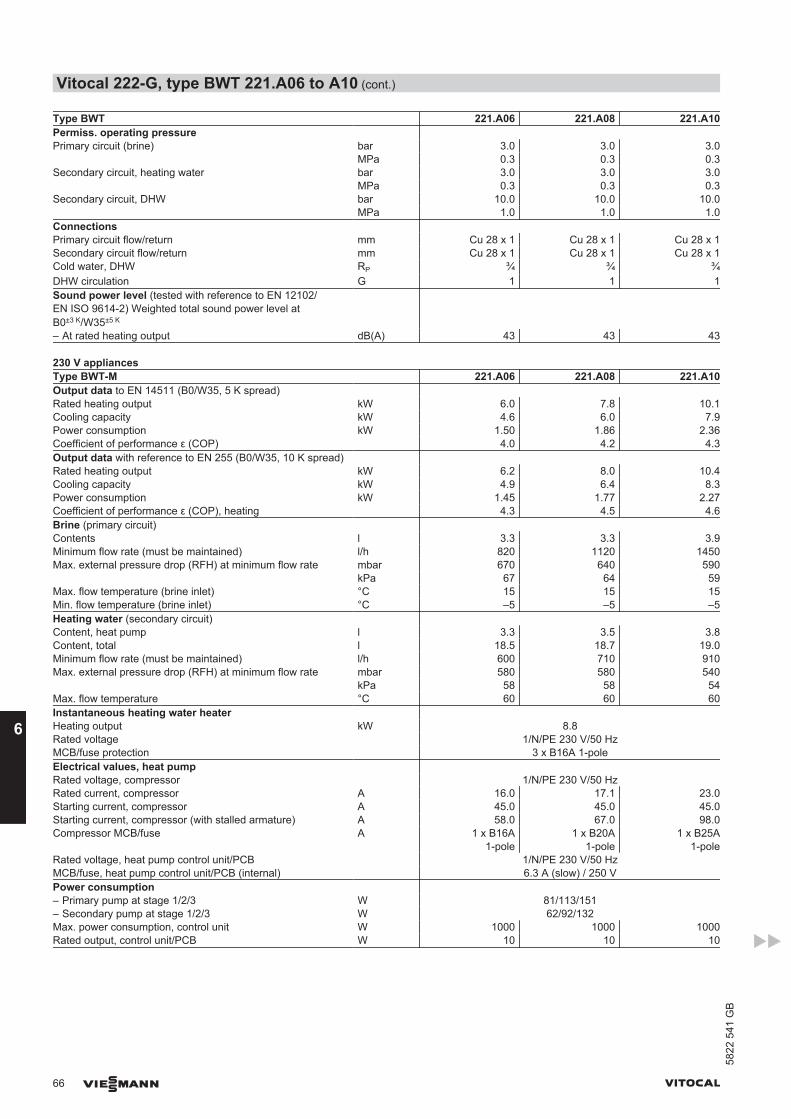
Type BWT 221.A06 221.A08 221.A10Permiss. operating pressure Primary circuit (brine) bar 3.0 3.0 3.0 MPa 0.3 0.3 0.3Secondary circuit, heating water bar 3.0 3.0 3.0 MPa 0.3 0.3 0.3Secondary circuit, DHW bar 10.0 10.0 10.0 MPa 1.0 1.0 1.0Connections Primary circuit flow/return mm Cu 28 x 1 Cu 28 x 1 Cu 28 x 1Secondary circuit flow/return mm Cu 28 x 1 Cu 28 x 1 Cu 28 x 1Cold water, DHW RP ¾ ¾ ¾DHW circulation G 1 1 1Sound power level (tested with reference to EN 12102/EN ISO 9614-2) Weighted total sound power level atB0±3 K/W35±5 K
– At rated heating output dB(A) 43 43 43
230 V appliancesType BWT-M 221.A06 221.A08 221.A10Output data to EN 14511 (B0/W35, 5 K spread) Rated heating output kW 6.0 7.8 10.1Cooling capacity kW 4.6 6.0 7.9Power consumption kW 1.50 1.86 2.36Coefficient of performance ε (COP) 4.0 4.2 4.3Output data with reference to EN 255 (B0/W35, 10 K spread) Rated heating output kW 6.2 8.0 10.4Cooling capacity kW 4.9 6.4 8.3Power consumption kW 1.45 1.77 2.27Coefficient of performance ε (COP), heating 4.3 4.5 4.6Brine (primary circuit) Contents l 3.3 3.3 3.9Minimum flow rate (must be maintained) l/h 820 1120 1450Max. external pressure drop (RFH) at minimum flow rate mbar 670 640 590 kPa 67 64 59Max. flow temperature (brine inlet) °C 15 15 15Min. flow temperature (brine inlet) °C –5 –5 –5Heating water (secondary circuit) Content, heat pump l 3.3 3.5 3.8Content, total l 18.5 18.7 19.0Minimum flow rate (must be maintained) l/h 600 710 910Max. external pressure drop (RFH) at minimum flow rate mbar 580 580 540 kPa 58 58 54Max. flow temperature °C 60 60 60Instantaneous heating water heater Heating output kW 8.8Rated voltage 1/N/PE 230 V/50 HzMCB/fuse protection 3 x B16A 1-poleElectrical values, heat pump Rated voltage, compressor 1/N/PE 230 V/50 HzRated current, compressor A 16.0 17.1 23.0Starting current, compressor A 45.0 45.0 45.0Starting current, compressor (with stalled armature) A 58.0 67.0 98.0Compressor MCB/fuse A 1 x B16A
1-pole1 x B20A
1-pole1 x B25A
1-poleRated voltage, heat pump control unit/PCB 1/N/PE 230 V/50 HzMCB/fuse, heat pump control unit/PCB (internal) 6.3 A (slow) / 250 VPower consumption – Primary pump at stage 1/2/3 W 81/113/151– Secondary pump at stage 1/2/3 W 62/92/132Max. power consumption, control unit W 1000 1000 1000Rated output, control unit/PCB W 10 10 10
Vitocal 222-G, type BWT 221.A06 to A10 (cont.)
66 VIESMANN VITOCAL
658
22 5
41 G
B

Type BWT-M 221.A06 221.A08 221.A10Refrigerant circuit Refrigerant R410A R410A R410ARefrigerant charge kg 1.8 1.8 2.05Compressor Type Hermetically sealed scrollPermiss. operating pressure – High pressure side bar 43 43 43 MPa 4.3 4.3 4.3– Low pressure side bar 28 28 28 MPa 2.8 2.8 2.8Integral DHW cylinder Contents l 170 170 170Continuous output for DHW heating from 10 to 60 °C l/h 241 275 309Performance factor NL to DIN 4708 1.0 1.1 1.3Max. draw-off rate at the specified performance factor NL andDHW heating from 10 to 45 °C
l/min 14.3 14.8 15.9
Max. permissible DHW temperature °C 95 95 95Dimensions – Total length mm 680 680 680– Total width mm 600 600 600– Total height mm 1829 1829 1829Total weight kg 250 250 256Permiss. operating pressure Primary circuit (brine) bar 3.0 3.0 3.0 MPa 0.3 0.3 0.3Secondary circuit, heating water bar 3.0 3.0 3.0 MPa 0.3 0.3 0.3Secondary circuit, DHW bar 10.0 10.0 10.0 MPa 1.0 1.0 1.0Connections Primary circuit flow/return mm Cu 28 x 1 Cu 28 x 1 Cu 28 x 1Secondary circuit flow/return mm Cu 28 x 1 Cu 28 x 1 Cu 28 x 1Cold water, DHW RP ¾ ¾ ¾DHW circulation G 1 1 1Sound power level (tested with reference to EN 12102/EN ISO 9614-2) Weighted total sound power level atB0±3 K/W35±5 K
– At rated heating output dB(A) 46 46 46
Vitocal 222-G, type BWT 221.A06 to A10 (cont.)
VITOCAL VIESMANN 67
5822
541
GB
6
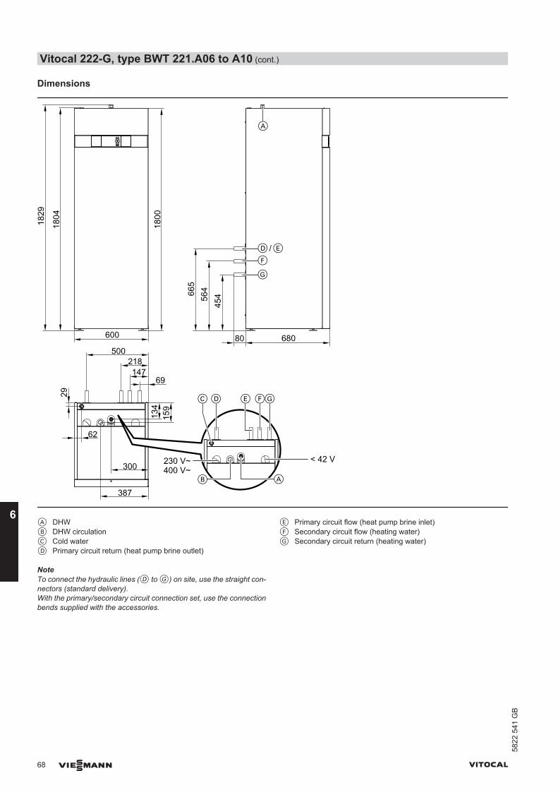
Dimensions
45456
4665
680
1804
1829
600
218147
69
134
159
62
300
387
500
1800
D E
F
G
A
D E GF
AB
C29
/
80
< 42 V230 V~400 V~
A DHWB DHW circulationC Cold waterD Primary circuit return (heat pump brine outlet)
E Primary circuit flow (heat pump brine inlet)F Secondary circuit flow (heating water)G Secondary circuit return (heating water)
NoteTo connect the hydraulic lines (D to G) on site, use the straight con-nectors (standard delivery).With the primary/secondary circuit connection set, use the connectionbends supplied with the accessories.
Vitocal 222-G, type BWT 221.A06 to A10 (cont.)
68 VIESMANN VITOCAL
658
22 5
41 G
B
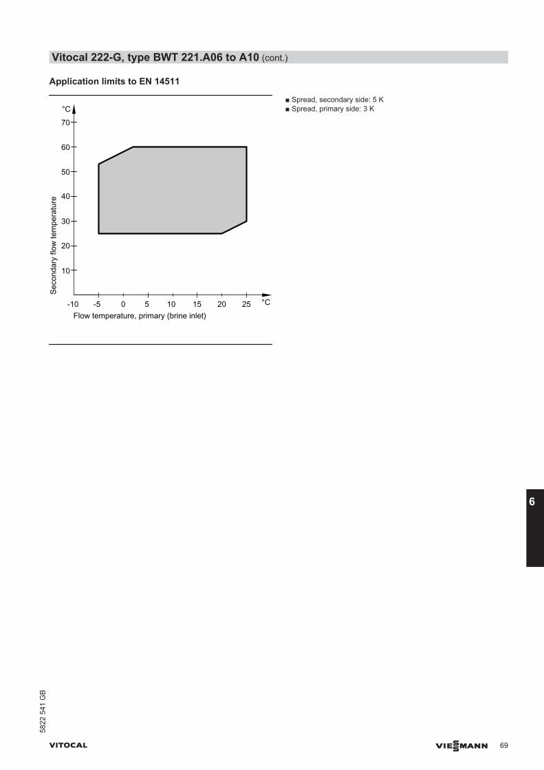
Application limits to EN 14511
Seco
ndar
y flo
w te
mpe
ratu
re
Flow temperature, primary (brine inlet)-5 0 5
°C
°C10 15 20 25-10
10
20
30
40
50
60
70
■ Spread, secondary side: 5 K■ Spread, primary side: 3 K
Vitocal 222-G, type BWT 221.A06 to A10 (cont.)
VITOCAL VIESMANN 69
5822
541
GB
6
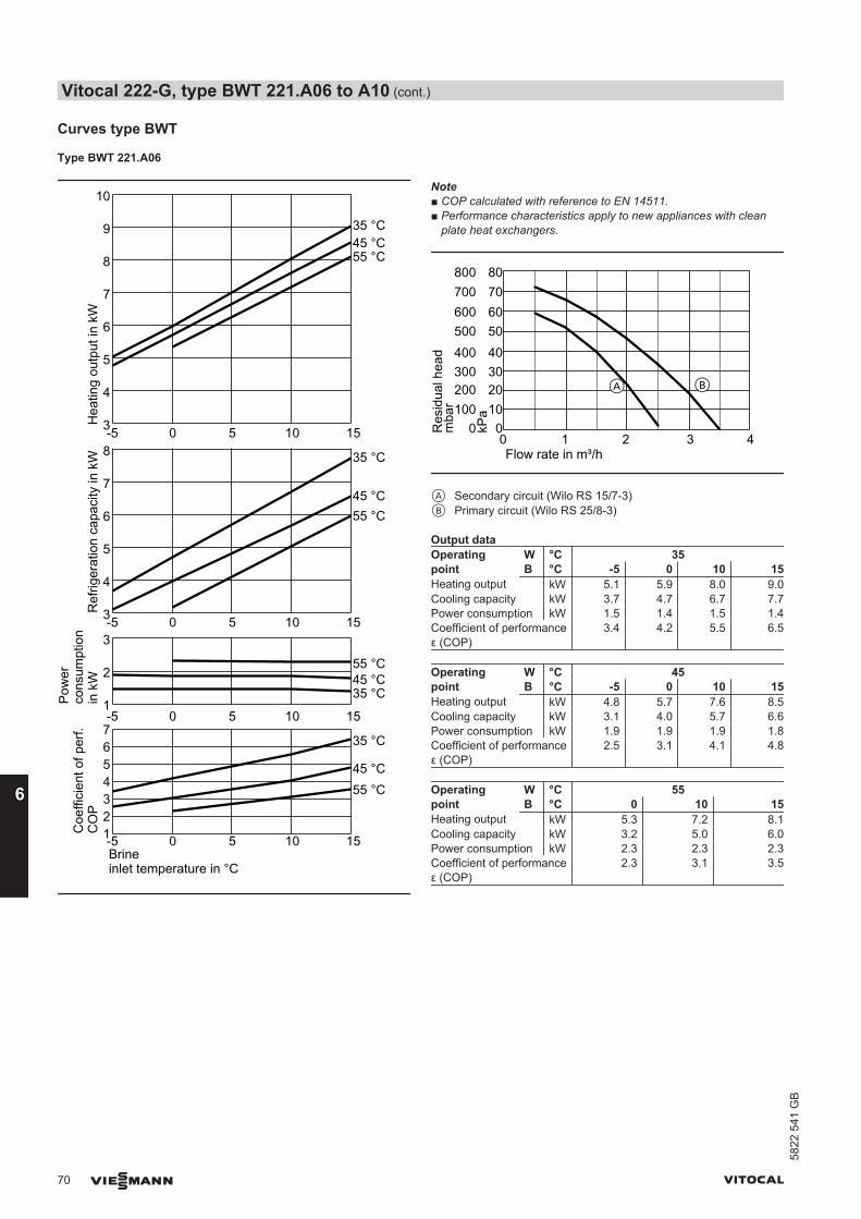
Curves type BWT
Type BWT 221.A06
1
2
3
1234567-5 0 5 10 15
3
4
5
6
7
8
9
10
-5 0 5 10 15
Coe
ffici
ent o
f per
f.C
OP
Ref
riger
atio
n ca
paci
ty in
kW
Pow
erco
nsum
ptio
n in
kW
Hea
ting
outp
ut in
kW
35 °C
45 °C55 °C
-5 0 5 10 15Brineinlet temperature in °C
3
4
5
6
7
8
-5 0 5 10 15
35 °C
45 °C55 °C
35 °C45 °C55 °C
35 °C45 °C55 °C
Note■ COP calculated with reference to EN 14511.■ Performance characteristics apply to new appliances with clean
plate heat exchangers.
100
300
500
700
0
200
400
600
800
Res
idua
l hea
d0 1 2 4Flow rate in m³/h
mba
r 10
30
50
70
0
20
40
60
80
kPa
A B
3
A Secondary circuit (Wilo RS 15/7-3)B Primary circuit (Wilo RS 25/8-3)
Output dataOperatingpoint
W °C 35B °C -5 0 10 15
Heating output kW 5.1 5.9 8.0 9.0Cooling capacity kW 3.7 4.7 6.7 7.7Power consumption kW 1.5 1.4 1.5 1.4Coefficient of performanceε (COP)
3.4 4.2 5.5 6.5
Operatingpoint
W °C 45B °C -5 0 10 15
Heating output kW 4.8 5.7 7.6 8.5Cooling capacity kW 3.1 4.0 5.7 6.6Power consumption kW 1.9 1.9 1.9 1.8Coefficient of performanceε (COP)
2.5 3.1 4.1 4.8
Operatingpoint
W °C 55B °C 0 10 15
Heating output kW 5.3 7.2 8.1Cooling capacity kW 3.2 5.0 6.0Power consumption kW 2.3 2.3 2.3Coefficient of performanceε (COP)
2.3 3.1 3.5
Vitocal 222-G, type BWT 221.A06 to A10 (cont.)
70 VIESMANN VITOCAL
658
22 5
41 G
B

Type BWT 221.A08
-5 0 5 10 15
1234567
2
4
0
-5 0 5 10 154
6
8
10
12
-5 0 5 10 154
6
8
10
-5 0 5 10 15Brineinlet temperature in °C
Coe
ffici
ent o
f per
f.C
OP
Ref
riger
atio
n ca
paci
ty in
kW
Pow
erco
nsum
ptio
n in
kW
Hea
ting
outp
ut in
kW
35 °C
45 °C
55 °C
35 °C
45 °C
55 °C
35 °C45 °C55 °C
35 °C45 °C55 °C
Note■ COP calculated with reference to EN 14511.■ Performance characteristics apply to new appliances with clean
plate heat exchangers.
0 1 2 3 4Flow rate in m³/h
100
300
500
700
0
200
400
600
800
Res
idua
l hea
dm
bar 10
30
50
70
0
20
40
60
80
kPa
A B
A Secondary circuit (Wilo RS 15/7-3)B Primary circuit (Wilo RS 25/8-3)
Output dataOperatingpoint
W °C 35B °C -5 0 10 15
Heating output kW 6.5 7.7 10.2 11.4Cooling capacity kW 4.8 6.0 8.5 9.8Power consumption kW 1.9 1.84 1.8 1.8Coefficient of performanceε (COP)
3.4 4.2 5.6 6.5
Operatingpoint
W °C 45B °C -5 0 10 15
Heating output kW 6.2 7.4 9.7 10.9Cooling capacity kW 4.1 5.2 7.4 8.5Power consumption kW 2.4 2.3 2.3 2.2Coefficient of performanceε (COP)
2.6 3.2 4.2 5.0
Operatingpoint
W °C 55B °C 0 10 15
Heating output kW 7.0 9.2 10.2Cooling capacity kW 4.3 6.5 7.6Power consumption kW 2.9 2.8 2.8Coefficient of performanceε (COP)
2.4 3.2 3.6
Vitocal 222-G, type BWT 221.A06 to A10 (cont.)
VITOCAL VIESMANN 71
5822
541
GB
6
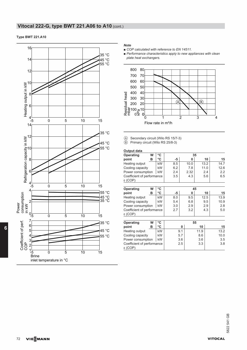
Type BWT 221.A10
1234567-5 0 5 10 15
-5 0 5 10 15Brineinlet temperature in °C
2
4
0
14
-5 0 5 10 154
6
8
10
12
16
14
-5 0 5 10 154
6
8
10
12
Coe
ffici
ent o
f per
f.C
OP
Ref
riger
atio
n ca
paci
ty in
kW
Pow
erco
nsum
ptio
n in
kW
Hea
ting
outp
ut in
kW
35 °C
45 °C55 °C
35 °C
45 °C55 °C
35 °C45 °C55 °C
35 °C45 °C55 °C
Note■ COP calculated with reference to EN 14511.■ Performance characteristics apply to new appliances with clean
plate heat exchangers.
00 1 2 3 4Flow rate in m³/h
100
300
500
700
0
200
400
600
800
Res
idua
l hea
dm
bar 10
30
50
70
0
20
40
60
80
kPa
BA
A Secondary circuit (Wilo RS 15/7-3)B Primary circuit (Wilo RS 25/8-3)
Output dataOperatingpoint
W °C 35B °C -5 0 10 15
Heating output kW 8.5 10.0 13.2 14.7Cooling capacity kW 6.2 7.8 11.0 12.6Power consumption kW 2.4 2.32 2.4 2.2Coefficient of performanceε (COP)
3.5 4.3 5.6 6.5
Operatingpoint
W °C 45B °C -5 0 10 15
Heating output kW 8.0 9.5 12.5 13.9Cooling capacity kW 5.4 6.8 9.5 10.9Power consumption kW 3.0 2.9 2.9 2.8Coefficient of performanceε (COP)
2.7 3.2 4.3 5.0
Operatingpoint
W °C 55B °C 0 10 15
Heating output kW 9.1 11.9 13.2Cooling capacity kW 5.7 8.6 10.0Power consumption kW 3.6 3.6 3.5Coefficient of performanceε (COP)
2.5 3.3 3.8
Vitocal 222-G, type BWT 221.A06 to A10 (cont.)
72 VIESMANN VITOCAL
658
22 5
41 G
B

Curves, type BWT-M
Type BWT-M 221.A06
01234567
-5 0 5 10 15Brineinlet temperature in °C
1
2
3
0-5 0 5 10 15
3
4
5
6
7
8
9
10
-5 0 5 10 15
3
4
5
6
7
8
-5 0 5 10 15
Coe
ffici
ent o
f per
f.C
OP
Ref
riger
atio
n ca
paci
ty in
kW
Pow
erco
nsum
ptio
n in
kW
Hea
ting
outp
ut in
kW
35 °C
45 °C55 °C
35 °C
45 °C
55 °C
35 °C45 °C55 °C
35 °C45 °C55 °C
Note■ COP calculated with reference to EN 14511.■ Performance characteristics apply to new appliances with clean
plate heat exchangers.
100
300
500
700
0
200
400
600
800
Res
idua
l hea
d0 1 2 4Flow rate in m³/h
mba
r 10
30
50
70
0
20
40
60
80
kPa
A B
3
A Secondary circuit (Wilo RS 15/7-3)B Primary circuit (Wilo RS 25/8-3)
Output dataOperatingpoint
W °C 35B °C -5 0 10 15
Heating output kW 5.0 6.0 7.9 8.9Cooling capacity kW 3.7 4.6 6.5 7.5Power consumption kW 1.45 1.5 1.5 1.4Coefficient of performanceε (COP)
3.3 4.0 5.3 6.1
Operatingpoint
W °C 45B °C -5 0 10 15
Heating output kW 4.8 5.7 7.5 8.4Cooling capacity kW 3.2 4.0 5.6 6.5Power consumption kW 1.9 1.8 1.9 1.8Coefficient of performanceε (COP)
2.6 3.1 4.0 4.7
Operatingpoint
W °C 55B °C 0 10 15
Heating output kW 5.5 7.1 7.9Cooling capacity kW 3.3 5.0 5.8Power consumption kW 2.3 2.3 2.3Coefficient of performanceε (COP)
2.4 3.1 3.5
Vitocal 222-G, type BWT 221.A06 to A10 (cont.)
VITOCAL VIESMANN 73
5822
541
GB
6
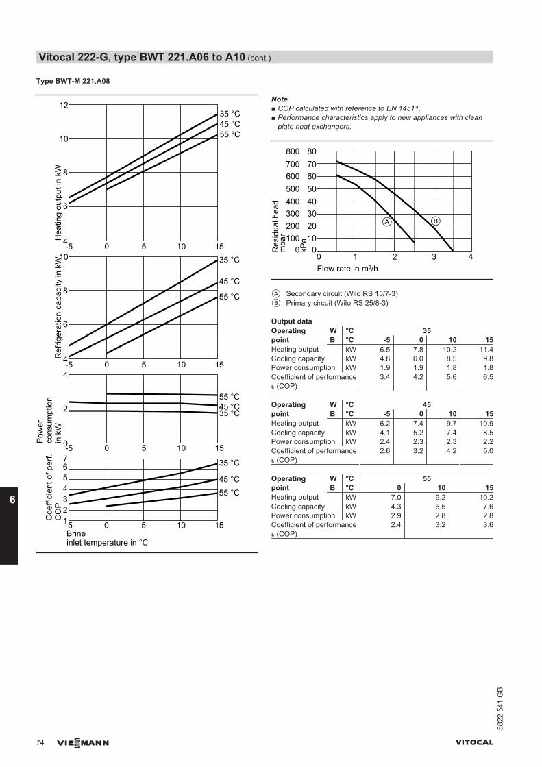
Type BWT-M 221.A08
-5 0 5 10 15
123
567
4
-5 0 5 10 15Brineinlet temperature in °C
2
4
0
-5 0 5 10 154
6
8
10
12
-5 0 5 10 154
6
8
10
Coe
ffici
ent o
f per
f.C
OP
Ref
riger
atio
n ca
paci
ty in
kW
Pow
erco
nsum
ptio
n in
kW
Hea
ting
outp
ut in
kW
35 °C
45 °C55 °C
35 °C
45 °C
55 °C
35 °C45 °C55 °C
35 °C45 °C55 °C
Note■ COP calculated with reference to EN 14511.■ Performance characteristics apply to new appliances with clean
plate heat exchangers.
0 1 2 3 4Flow rate in m³/h
100
300
500
700
0
200
400
600
800
Res
idua
l hea
dm
bar 10
30
50
70
0
20
40
60
80
kPa
A B
A Secondary circuit (Wilo RS 15/7-3)B Primary circuit (Wilo RS 25/8-3)
Output dataOperatingpoint
W °C 35B °C -5 0 10 15
Heating output kW 6.5 7.8 10.2 11.4Cooling capacity kW 4.8 6.0 8.5 9.8Power consumption kW 1.9 1.9 1.8 1.8Coefficient of performanceε (COP)
3.4 4.2 5.6 6.5
Operatingpoint
W °C 45B °C -5 0 10 15
Heating output kW 6.2 7.4 9.7 10.9Cooling capacity kW 4.1 5.2 7.4 8.5Power consumption kW 2.4 2.3 2.3 2.2Coefficient of performanceε (COP)
2.6 3.2 4.2 5.0
Operatingpoint
W °C 55B °C 0 10 15
Heating output kW 7.0 9.2 10.2Cooling capacity kW 4.3 6.5 7.6Power consumption kW 2.9 2.8 2.8Coefficient of performanceε (COP)
2.4 3.2 3.6
Vitocal 222-G, type BWT 221.A06 to A10 (cont.)
74 VIESMANN VITOCAL
658
22 5
41 G
B
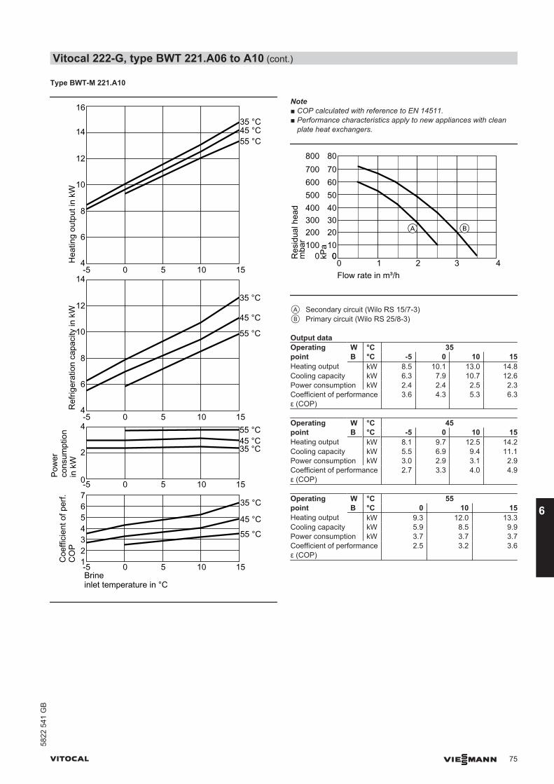
Type BWT-M 221.A10
4
6
8
10
12
14
1234567
Coe
ffici
ent o
f per
f.C
OP
Ref
riger
atio
n ca
paci
ty in
kW
Pow
erco
nsum
ptio
n in
kW
Hea
ting
outp
ut in
kW
35 °C
45 °C
55 °C
35 °C
45 °C
55 °C
35 °C45 °C55 °C
35 °C45 °C55 °C
-5 0 5 10 15Brineinlet temperature in °C
-5 0 5 10 15
2
4
0-5 0 5 10 15
4
6
8
10
12
14
16
-5 0 5 10 15
Note■ COP calculated with reference to EN 14511.■ Performance characteristics apply to new appliances with clean
plate heat exchangers.
00 1 2 3 4Flow rate in m³/h
100
300
500
700
0
200
400
600
800
Res
idua
l hea
dm
bar 10
30
50
70
0
20
40
60
80
kPa
BA
A Secondary circuit (Wilo RS 15/7-3)B Primary circuit (Wilo RS 25/8-3)
Output dataOperatingpoint
W °C 35B °C -5 0 10 15
Heating output kW 8.5 10.1 13.0 14.8Cooling capacity kW 6.3 7.9 10.7 12.6Power consumption kW 2.4 2.4 2.5 2.3Coefficient of performanceε (COP)
3.6 4.3 5.3 6.3
Operatingpoint
W °C 45B °C -5 0 10 15
Heating output kW 8.1 9.7 12.5 14.2Cooling capacity kW 5.5 6.9 9.4 11.1Power consumption kW 3.0 2.9 3.1 2.9Coefficient of performanceε (COP)
2.7 3.3 4.0 4.9
Operatingpoint
W °C 55B °C 0 10 15
Heating output kW 9.3 12.0 13.3Cooling capacity kW 5.9 8.5 9.9Power consumption kW 3.7 3.7 3.7Coefficient of performanceε (COP)
2.5 3.2 3.6
Vitocal 222-G, type BWT 221.A06 to A10 (cont.)
VITOCAL VIESMANN 75
5822
541
GB
6
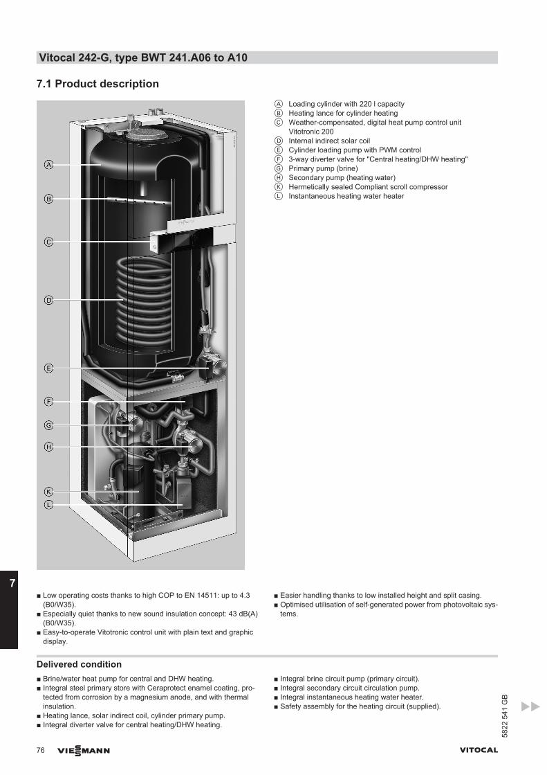
7.1 Product descriptionA Loading cylinder with 220 l capacityB Heating lance for cylinder heatingC Weather-compensated, digital heat pump control unit
Vitotronic 200D Internal indirect solar coilE Cylinder loading pump with PWM controlF 3-way diverter valve for "Central heating/DHW heating"G Primary pump (brine)H Secondary pump (heating water)K Hermetically sealed Compliant scroll compressorL Instantaneous heating water heater
■ Low operating costs thanks to high COP to EN 14511: up to 4.3(B0/W35).
■ Especially quiet thanks to new sound insulation concept: 43 dB(A)(B0/W35).
■ Easy-to-operate Vitotronic control unit with plain text and graphicdisplay.
■ Easier handling thanks to low installed height and split casing.■ Optimised utilisation of self-generated power from photovoltaic sys-
tems.
Delivered condition■ Brine/water heat pump for central and DHW heating.■ Integral steel primary store with Ceraprotect enamel coating, pro-
tected from corrosion by a magnesium anode, and with thermalinsulation.
■ Heating lance, solar indirect coil, cylinder primary pump.■ Integral diverter valve for central heating/DHW heating.
■ Integral brine circuit pump (primary circuit).■ Integral secondary circuit circulation pump.■ Integral instantaneous heating water heater.■ Safety assembly for the heating circuit (supplied).
Vitocal 242-G, type BWT 241.A06 to A10
76 VIESMANN VITOCAL
7
5822
541
GB

■ Weather-compensated Vitotronic 200 heat pump control unit withoutside temperature sensor.
■ Connection pipes for flow and return for the primary and secondarycircuits.
Vitocal 242-G, type BWT 241.A06 to A10 (cont.)
VITOCAL VIESMANN 77
5822
541
GB
7
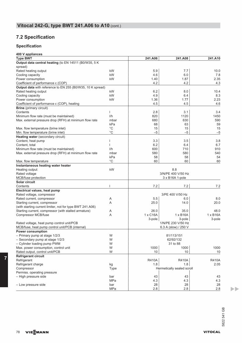
7.2 Specification
Specification
400 V appliancesType BWT 241.A06 241.A08 241.A10Output data central heating (to EN 14511 (B0/W35, 5 Kspread)
Rated heating output kW 5.9 7.7 10.0Cooling capacity kW 4.6 6.0 7.8Power consumption kW 1.40 1.87 2.35Coefficient of performance ε (COP) 4.2 4.2 4.3Output data with reference to EN 255 (B0/W35, 10 K spread) Rated heating output kW 6.2 8.0 10.4Cooling capacity kW 4.9 6.4 8.3Power consumption kW 1.36 1.77 2.23Coefficient of performance ε (COP), heating 4.5 4.5 4.6Brine (primary circuit) Contents l 2.8 3.1 3.4Minimum flow rate (must be maintained) l/h 820 1120 1450Max. external pressure drop (RFH) at minimum flow rate mbar 680 630 590 kPa 68 63 59Max. flow temperature (brine inlet) °C 15 15 15Min. flow temperature (brine inlet) °C –5 –5 –5Heating water (secondary circuit) Content, heat pump l 3.3 3.5 3.8Content, total l 6.2 6.4 6.7Minimum flow rate (must be maintained) l/h 600 710 910Max. external pressure drop (RFH) at minimum flow rate mbar 580 580 540 kPa 58 58 54Max. flow temperature °C 60 60 60Instantaneous heating water heater Heating output kW 8.8Rated voltage 3/N/PE 400 V/50 HzMCB/fuse protection 3 x B16A 1-poleSolar circuit Contents l 7.2 7.2 7.2Electrical values, heat pump Rated voltage, compressor 3/PE 400 V/50 HzRated current, compressor A 5.5 6.0 8.0Starting current, compressor(with starting current limiter, not for type BWT 241.A06)
A 25.0 14.0 20.0
Starting current, compressor (with stalled armature) A 26.0 35.0 48.0Compressor MCB/fuse A 1 x C16A
3-pole1 x B16A
3-pole1 x B16A
3-poleRated voltage, heat pump control unit/PCB 1/N/PE 230 V/50 HzMCB/fuse, heat pump control unit/PCB (internal) 6.3 A (slow) / 250 VPower consumption – Primary pump at stage 1/2/3 W 81/113/151– Secondary pump at stage 1/2/3 W 62/92/132– Cylinder loading pump PWM W 31 to 88Max. power consumption, control unit W 1000 1000 1000Rated output, control unit/PCB W 10 10 10Refrigerant circuit Refrigerant R410A R410A R410ARefrigerant charge kg 1.8 1.8 2.05Compressor Type Hermetically sealed scrollPermiss. operating pressure – High pressure side bar 43 43 43 MPa 4.3 4.3 4.3– Low pressure side bar 28 28 28 MPa 2.8 2.8 2.8
Vitocal 242-G, type BWT 241.A06 to A10 (cont.)
78 VIESMANN VITOCAL
7
5822
541
GB
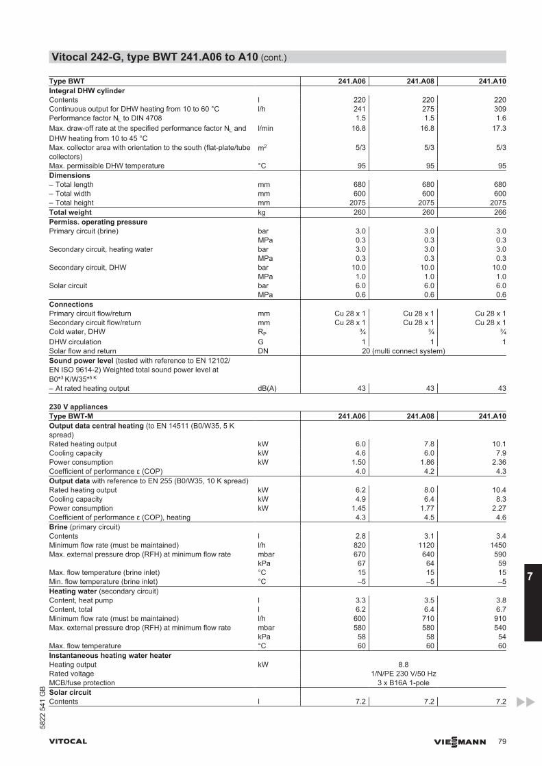
Type BWT 241.A06 241.A08 241.A10Integral DHW cylinder Contents l 220 220 220Continuous output for DHW heating from 10 to 60 °C l/h 241 275 309Performance factor NL to DIN 4708 1.5 1.5 1.6Max. draw-off rate at the specified performance factor NL andDHW heating from 10 to 45 °C
l/min 16.8 16.8 17.3
Max. collector area with orientation to the south (flat-plate/tubecollectors)
m2 5/3 5/3 5/3
Max. permissible DHW temperature °C 95 95 95Dimensions – Total length mm 680 680 680– Total width mm 600 600 600– Total height mm 2075 2075 2075Total weight kg 260 260 266Permiss. operating pressure Primary circuit (brine) bar 3.0 3.0 3.0 MPa 0.3 0.3 0.3Secondary circuit, heating water bar 3.0 3.0 3.0 MPa 0.3 0.3 0.3Secondary circuit, DHW bar 10.0 10.0 10.0 MPa 1.0 1.0 1.0Solar circuit bar 6.0 6.0 6.0 MPa 0.6 0.6 0.6Connections Primary circuit flow/return mm Cu 28 x 1 Cu 28 x 1 Cu 28 x 1Secondary circuit flow/return mm Cu 28 x 1 Cu 28 x 1 Cu 28 x 1Cold water, DHW RP ¾ ¾ ¾DHW circulation G 1 1 1Solar flow and return DN 20 (multi connect system)Sound power level (tested with reference to EN 12102/EN ISO 9614-2) Weighted total sound power level atB0±3 K/W35±5 K
– At rated heating output dB(A) 43 43 43
230 V appliancesType BWT-M 241.A06 241.A08 241.A10Output data central heating (to EN 14511 (B0/W35, 5 Kspread)
Rated heating output kW 6.0 7.8 10.1Cooling capacity kW 4.6 6.0 7.9Power consumption kW 1.50 1.86 2.36Coefficient of performance ε (COP) 4.0 4.2 4.3Output data with reference to EN 255 (B0/W35, 10 K spread) Rated heating output kW 6.2 8.0 10.4Cooling capacity kW 4.9 6.4 8.3Power consumption kW 1.45 1.77 2.27Coefficient of performance ε (COP), heating 4.3 4.5 4.6Brine (primary circuit) Contents l 2.8 3.1 3.4Minimum flow rate (must be maintained) l/h 820 1120 1450Max. external pressure drop (RFH) at minimum flow rate mbar 670 640 590 kPa 67 64 59Max. flow temperature (brine inlet) °C 15 15 15Min. flow temperature (brine inlet) °C –5 –5 –5Heating water (secondary circuit) Content, heat pump l 3.3 3.5 3.8Content, total l 6.2 6.4 6.7Minimum flow rate (must be maintained) l/h 600 710 910Max. external pressure drop (RFH) at minimum flow rate mbar 580 580 540 kPa 58 58 54Max. flow temperature °C 60 60 60Instantaneous heating water heater Heating output kW 8.8Rated voltage 1/N/PE 230 V/50 HzMCB/fuse protection 3 x B16A 1-poleSolar circuit Contents l 7.2 7.2 7.2
Vitocal 242-G, type BWT 241.A06 to A10 (cont.)
VITOCAL VIESMANN 79
5822
541
GB
7
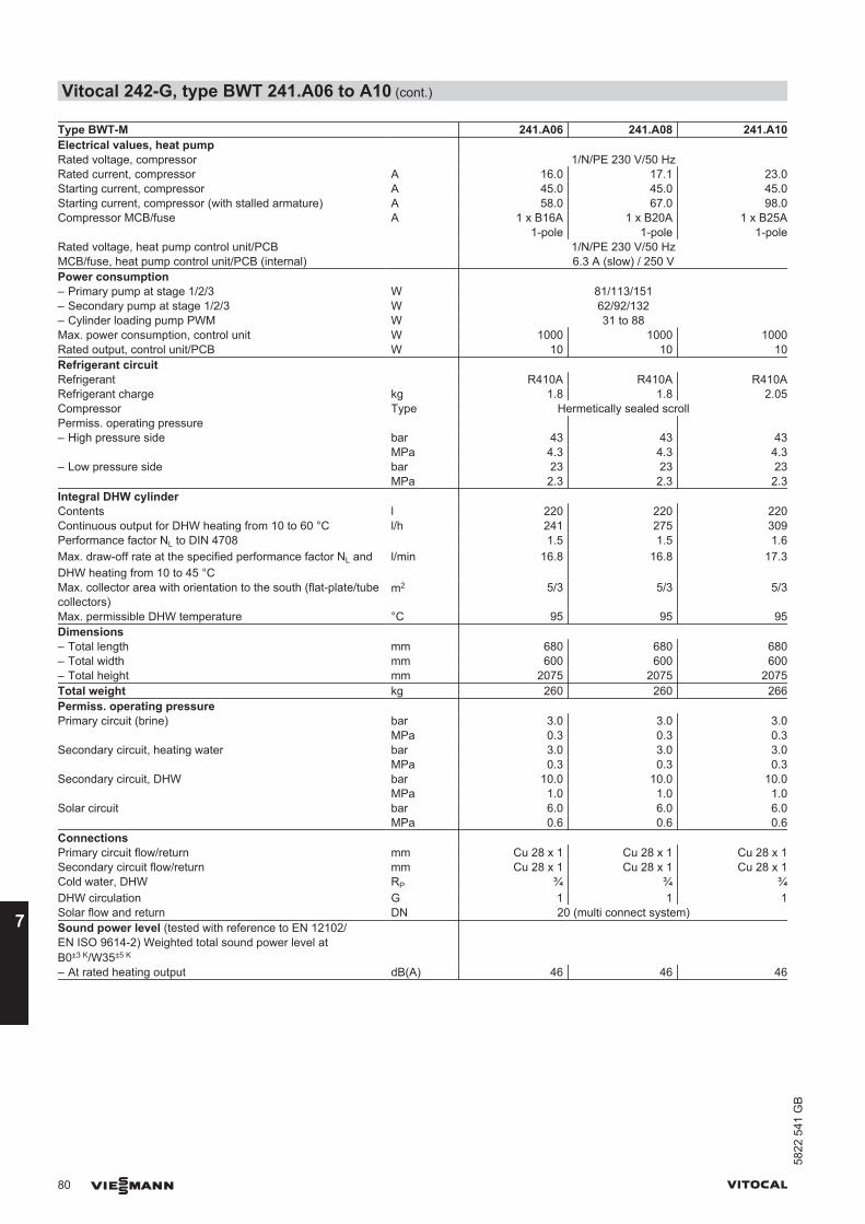
Type BWT-M 241.A06 241.A08 241.A10Electrical values, heat pump Rated voltage, compressor 1/N/PE 230 V/50 HzRated current, compressor A 16.0 17.1 23.0Starting current, compressor A 45.0 45.0 45.0Starting current, compressor (with stalled armature) A 58.0 67.0 98.0Compressor MCB/fuse A 1 x B16A
1-pole1 x B20A
1-pole1 x B25A
1-poleRated voltage, heat pump control unit/PCB 1/N/PE 230 V/50 HzMCB/fuse, heat pump control unit/PCB (internal) 6.3 A (slow) / 250 VPower consumption – Primary pump at stage 1/2/3 W 81/113/151– Secondary pump at stage 1/2/3 W 62/92/132– Cylinder loading pump PWM W 31 to 88Max. power consumption, control unit W 1000 1000 1000Rated output, control unit/PCB W 10 10 10Refrigerant circuit Refrigerant R410A R410A R410ARefrigerant charge kg 1.8 1.8 2.05Compressor Type Hermetically sealed scrollPermiss. operating pressure – High pressure side bar 43 43 43 MPa 4.3 4.3 4.3– Low pressure side bar 23 23 23 MPa 2.3 2.3 2.3Integral DHW cylinder Contents l 220 220 220Continuous output for DHW heating from 10 to 60 °C l/h 241 275 309Performance factor NL to DIN 4708 1.5 1.5 1.6Max. draw-off rate at the specified performance factor NL andDHW heating from 10 to 45 °C
l/min 16.8 16.8 17.3
Max. collector area with orientation to the south (flat-plate/tubecollectors)
m2 5/3 5/3 5/3
Max. permissible DHW temperature °C 95 95 95Dimensions – Total length mm 680 680 680– Total width mm 600 600 600– Total height mm 2075 2075 2075Total weight kg 260 260 266Permiss. operating pressure Primary circuit (brine) bar 3.0 3.0 3.0 MPa 0.3 0.3 0.3Secondary circuit, heating water bar 3.0 3.0 3.0 MPa 0.3 0.3 0.3Secondary circuit, DHW bar 10.0 10.0 10.0 MPa 1.0 1.0 1.0Solar circuit bar 6.0 6.0 6.0 MPa 0.6 0.6 0.6Connections Primary circuit flow/return mm Cu 28 x 1 Cu 28 x 1 Cu 28 x 1Secondary circuit flow/return mm Cu 28 x 1 Cu 28 x 1 Cu 28 x 1Cold water, DHW RP ¾ ¾ ¾DHW circulation G 1 1 1Solar flow and return DN 20 (multi connect system)Sound power level (tested with reference to EN 12102/EN ISO 9614-2) Weighted total sound power level atB0±3 K/W35±5 K
– At rated heating output dB(A) 46 46 46
Vitocal 242-G, type BWT 241.A06 to A10 (cont.)
80 VIESMANN VITOCAL
7
5822
541
GB
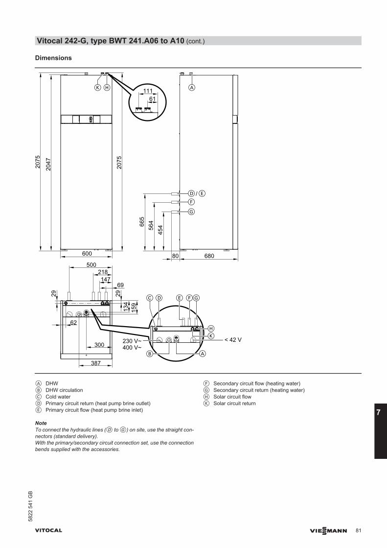
Dimensions20
47
2075
45456
4665
2075
600 680500
218147
69
29
300
387
134
159
62
D E GF
AB
C
HK
D E
F
G
AHK
29
/
61111
80
< 42 V230 V~400 V~
A DHWB DHW circulationC Cold waterD Primary circuit return (heat pump brine outlet)E Primary circuit flow (heat pump brine inlet)
F Secondary circuit flow (heating water)G Secondary circuit return (heating water)H Solar circuit flowK Solar circuit return
NoteTo connect the hydraulic lines (D to G) on site, use the straight con-nectors (standard delivery).With the primary/secondary circuit connection set, use the connectionbends supplied with the accessories.
Vitocal 242-G, type BWT 241.A06 to A10 (cont.)
VITOCAL VIESMANN 81
5822
541
GB
7
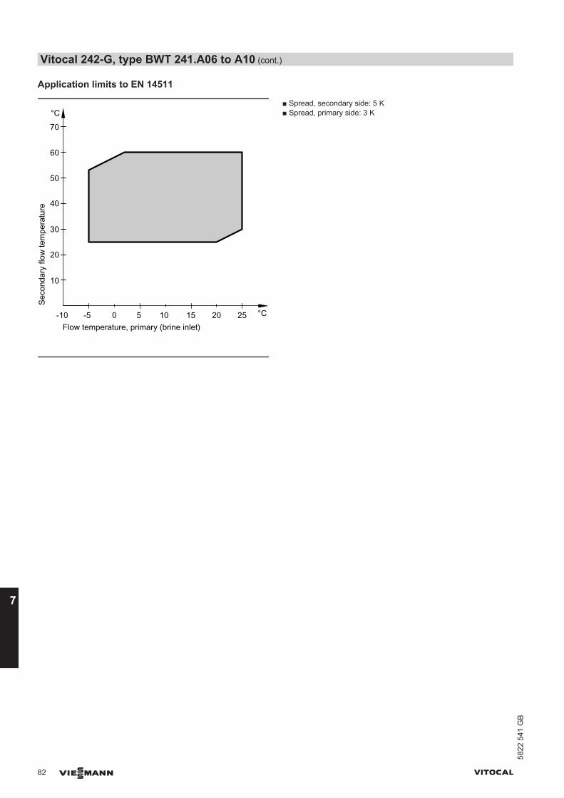
Application limits to EN 14511
Seco
ndar
y flo
w te
mpe
ratu
re
Flow temperature, primary (brine inlet)-5 0 5
°C
°C10 15 20 25-10
10
20
30
40
50
60
70
■ Spread, secondary side: 5 K■ Spread, primary side: 3 K
Vitocal 242-G, type BWT 241.A06 to A10 (cont.)
82 VIESMANN VITOCAL
7
5822
541
GB
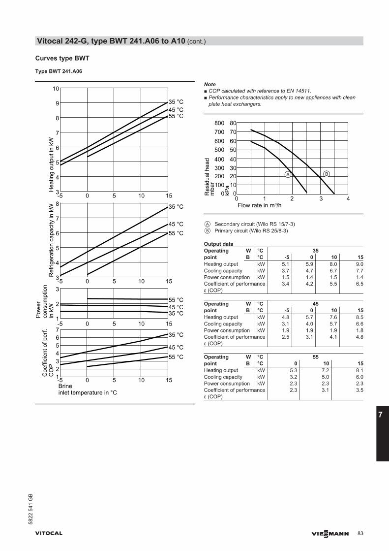
Curves type BWT
Type BWT 241.A06
1
2
3
1234567-5 0 5 10 15
3
4
5
6
7
8
9
10
-5 0 5 10 15
Coe
ffici
ent o
f per
f.C
OP
Ref
riger
atio
n ca
paci
ty in
kW
Pow
erco
nsum
ptio
n in
kW
Hea
ting
outp
ut in
kW
35 °C
45 °C55 °C
-5 0 5 10 15Brineinlet temperature in °C
3
4
5
6
7
8
-5 0 5 10 15
35 °C
45 °C55 °C
35 °C45 °C55 °C
35 °C45 °C55 °C
Note■ COP calculated with reference to EN 14511.■ Performance characteristics apply to new appliances with clean
plate heat exchangers.
100
300
500
700
0
200
400
600
800
Res
idua
l hea
d0 1 2 4Flow rate in m³/h
mba
r 10
30
50
70
0
20
40
60
80
kPa
A B
3
A Secondary circuit (Wilo RS 15/7-3)B Primary circuit (Wilo RS 25/8-3)
Output dataOperatingpoint
W °C 35B °C -5 0 10 15
Heating output kW 5.1 5.9 8.0 9.0Cooling capacity kW 3.7 4.7 6.7 7.7Power consumption kW 1.5 1.4 1.5 1.4Coefficient of performanceε (COP)
3.4 4.2 5.5 6.5
Operatingpoint
W °C 45B °C -5 0 10 15
Heating output kW 4.8 5.7 7.6 8.5Cooling capacity kW 3.1 4.0 5.7 6.6Power consumption kW 1.9 1.9 1.9 1.8Coefficient of performanceε (COP)
2.5 3.1 4.1 4.8
Operatingpoint
W °C 55B °C 0 10 15
Heating output kW 5.3 7.2 8.1Cooling capacity kW 3.2 5.0 6.0Power consumption kW 2.3 2.3 2.3Coefficient of performanceε (COP)
2.3 3.1 3.5
Vitocal 242-G, type BWT 241.A06 to A10 (cont.)
VITOCAL VIESMANN 83
5822
541
GB
7

Type BWT 241.A08
-5 0 5 10 15
1234567
2
4
0
-5 0 5 10 154
6
8
10
12
-5 0 5 10 154
6
8
10
-5 0 5 10 15Brineinlet temperature in °C
Coe
ffici
ent o
f per
f.C
OP
Ref
riger
atio
n ca
paci
ty in
kW
Pow
erco
nsum
ptio
n in
kW
Hea
ting
outp
ut in
kW
35 °C
45 °C
55 °C
35 °C
45 °C
55 °C
35 °C45 °C55 °C
35 °C45 °C55 °C
Note■ COP calculated with reference to EN 14511.■ Performance characteristics apply to new appliances with clean
plate heat exchangers.
0 1 2 3 4Flow rate in m³/h
100
300
500
700
0
200
400
600
800
Res
idua
l hea
dm
bar 10
30
50
70
0
20
40
60
80
kPa
A B
A Secondary circuit (Wilo RS 15/7-3)B Primary circuit (Wilo RS 25/8-3)
Output dataOperatingpoint
W °C 35B °C -5 0 10 15
Heating output kW 6.5 7.7 10.2 11.4Cooling capacity kW 4.8 6.0 8.5 9.8Power consumption kW 1.9 1.84 1.8 1.8Coefficient of performanceε (COP)
3.4 4.2 5.6 6.5
Operatingpoint
W °C 45B °C -5 0 10 15
Heating output kW 6.2 7.4 9.7 10.9Cooling capacity kW 4.1 5.2 7.4 8.5Power consumption kW 2.4 2.3 2.3 2.2Coefficient of performanceε (COP)
2.6 3.2 4.2 5.0
Operatingpoint
W °C 55B °C 0 10 15
Heating output kW 7.0 9.2 10.2Cooling capacity kW 4.3 6.5 7.6Power consumption kW 2.9 2.8 2.8Coefficient of performanceε (COP)
2.4 3.2 3.6
Vitocal 242-G, type BWT 241.A06 to A10 (cont.)
84 VIESMANN VITOCAL
7
5822
541
GB
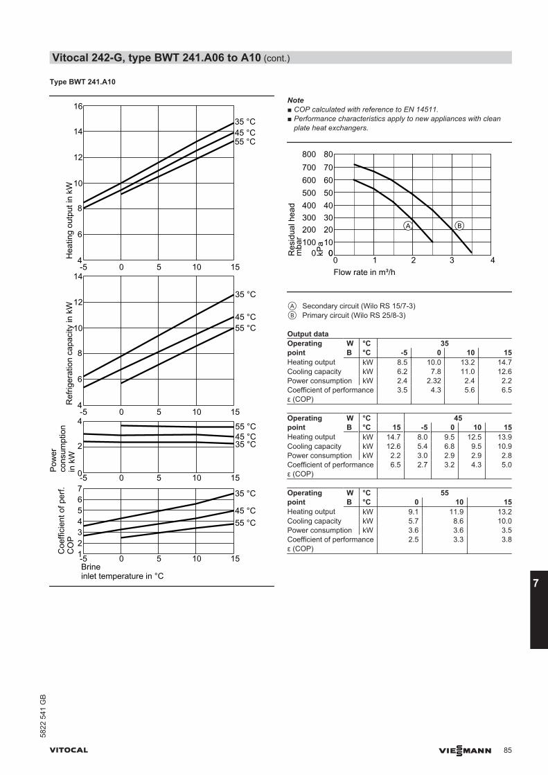
Type BWT 241.A10
1234567-5 0 5 10 15
-5 0 5 10 15Brineinlet temperature in °C
2
4
0
14
-5 0 5 10 154
6
8
10
12
16
14
-5 0 5 10 154
6
8
10
12
Coe
ffici
ent o
f per
f.C
OP
Ref
riger
atio
n ca
paci
ty in
kW
Pow
erco
nsum
ptio
n in
kW
Hea
ting
outp
ut in
kW
35 °C
45 °C55 °C
35 °C
45 °C55 °C
35 °C45 °C55 °C
35 °C45 °C55 °C
Note■ COP calculated with reference to EN 14511.■ Performance characteristics apply to new appliances with clean
plate heat exchangers.
00 1 2 3 4Flow rate in m³/h
100
300
500
700
0
200
400
600
800
Res
idua
l hea
dm
bar 10
30
50
70
0
20
40
60
80
kPa
BA
A Secondary circuit (Wilo RS 15/7-3)B Primary circuit (Wilo RS 25/8-3)
Output dataOperatingpoint
W °C 35B °C -5 0 10 15
Heating output kW 8.5 10.0 13.2 14.7Cooling capacity kW 6.2 7.8 11.0 12.6Power consumption kW 2.4 2.32 2.4 2.2Coefficient of performanceε (COP)
3.5 4.3 5.6 6.5
Operatingpoint
W °C 45B °C 15 -5 0 10 15
Heating output kW 14.7 8.0 9.5 12.5 13.9Cooling capacity kW 12.6 5.4 6.8 9.5 10.9Power consumption kW 2.2 3.0 2.9 2.9 2.8Coefficient of performanceε (COP)
6.5 2.7 3.2 4.3 5.0
Operatingpoint
W °C 55B °C 0 10 15
Heating output kW 9.1 11.9 13.2Cooling capacity kW 5.7 8.6 10.0Power consumption kW 3.6 3.6 3.5Coefficient of performanceε (COP)
2.5 3.3 3.8
Vitocal 242-G, type BWT 241.A06 to A10 (cont.)
VITOCAL VIESMANN 85
5822
541
GB
7

Curves, type BWT-M
Type BWT-M 241.A06
01234567
-5 0 5 10 15Brineinlet temperature in °C
1
2
3
0-5 0 5 10 15
3
4
5
6
7
8
9
10
-5 0 5 10 15
3
4
5
6
7
8
-5 0 5 10 15
Coe
ffici
ent o
f per
f.C
OP
Ref
riger
atio
n ca
paci
ty in
kW
Pow
erco
nsum
ptio
n in
kW
Hea
ting
outp
ut in
kW
35 °C
45 °C55 °C
35 °C
45 °C
55 °C
35 °C45 °C55 °C
35 °C45 °C55 °C
Note■ COP calculated with reference to EN 14511.■ Performance characteristics apply to new appliances with clean
plate heat exchangers.
100
300
500
700
0
200
400
600
800
Res
idua
l hea
d0 1 2 4Flow rate in m³/h
mba
r 10
30
50
70
0
20
40
60
80
kPa
A B
3
A Secondary circuit (Wilo RS 15/7-3)B Primary circuit (Wilo RS 25/8-3)
Output dataOperatingpoint
W °C 35B °C -5 0 10 15
Heating output kW 5.0 6.0 7.9 8.9Cooling capacity kW 3.7 4.6 6.5 7.5Power consumption kW 1.45 1.5 1.5 1.4Coefficient of performanceε (COP)
3.3 4.0 5.3 6.1
Operatingpoint
W °C 45B °C -5 0 10 15
Heating output kW 4.8 5.7 7.5 8.4Cooling capacity kW 3.2 4.0 5.6 6.5Power consumption kW 1.9 1.8 1.9 1.8Coefficient of performanceε (COP)
2.6 3.1 4.0 4.7
Operatingpoint
W °C 55B °C 0 10 15
Heating output kW 5.5 7.1 7.9Cooling capacity kW 3.3 5.0 5.8Power consumption kW 2.3 2.3 2.3Coefficient of performanceε (COP)
2.4 3.1 3.5
Vitocal 242-G, type BWT 241.A06 to A10 (cont.)
86 VIESMANN VITOCAL
7
5822
541
GB

Type BWT-M 241.A08
-5 0 5 10 15
123
567
4
-5 0 5 10 15Brineinlet temperature in °C
2
4
0
-5 0 5 10 154
6
8
10
12
-5 0 5 10 154
6
8
10
Coe
ffici
ent o
f per
f.C
OP
Ref
riger
atio
n ca
paci
ty in
kW
Pow
erco
nsum
ptio
n in
kW
Hea
ting
outp
ut in
kW
35 °C
45 °C55 °C
35 °C
45 °C
55 °C
35 °C45 °C55 °C
35 °C45 °C55 °C
Note■ COP calculated with reference to EN 14511.■ Performance characteristics apply to new appliances with clean
plate heat exchangers.
0 1 2 3 4Flow rate in m³/h
100
300
500
700
0
200
400
600
800
Res
idua
l hea
dm
bar 10
30
50
70
0
20
40
60
80
kPa
A B
A Secondary circuit (Wilo RS 15/7-3)B Primary circuit (Wilo RS 25/8-3)
Output dataOperatingpoint
W °C 35B °C -5 0 10 15
Heating output kW 6.5 7.8 10.2 11.4Cooling capacity kW 4.8 6.0 8.5 9.8Power consumption kW 1.9 1.9 1.8 1.8Coefficient of performanceε (COP)
3.4 4.2 5.6 6.5
Operatingpoint
W °C 45B °C -5 0 10 15
Heating output kW 6.2 7.4 9.7 10.9Cooling capacity kW 4.1 5.2 7.4 8.5Power consumption kW 2.4 2.3 2.3 2.2Coefficient of performanceε (COP)
2.6 3.2 4.2 5.0
Operatingpoint
W °C 55B °C 0 10 15
Heating output kW 7.0 9.2 10.2Cooling capacity kW 4.3 6.5 7.6Power consumption kW 2.9 2.8 2.8Coefficient of performanceε (COP)
2.4 3.2 3.6
Vitocal 242-G, type BWT 241.A06 to A10 (cont.)
VITOCAL VIESMANN 87
5822
541
GB
7
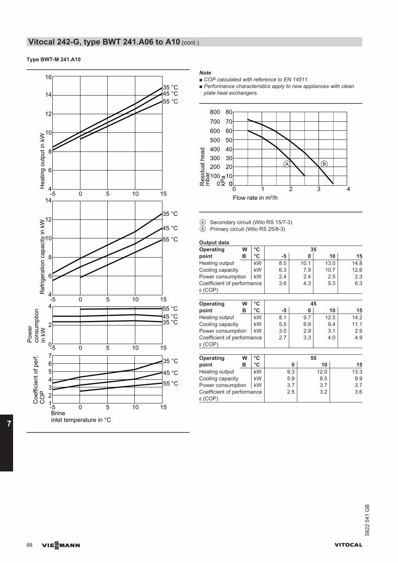
Type BWT-M 241.A10
4
6
8
10
12
14
1234567
Coe
ffici
ent o
f per
f.C
OP
Ref
riger
atio
n ca
paci
ty in
kW
Pow
erco
nsum
ptio
n in
kW
Hea
ting
outp
ut in
kW
35 °C
45 °C
55 °C
35 °C
45 °C
55 °C
35 °C45 °C55 °C
35 °C45 °C55 °C
-5 0 5 10 15Brineinlet temperature in °C
-5 0 5 10 15
2
4
0-5 0 5 10 15
4
6
8
10
12
14
16
-5 0 5 10 15
Note■ COP calculated with reference to EN 14511.■ Performance characteristics apply to new appliances with clean
plate heat exchangers.
00 1 2 3 4Flow rate in m³/h
100
300
500
700
0
200
400
600
800
Res
idua
l hea
dm
bar 10
30
50
70
0
20
40
60
80
kPa
BA
A Secondary circuit (Wilo RS 15/7-3)B Primary circuit (Wilo RS 25/8-3)
Output dataOperatingpoint
W °C 35B °C -5 0 10 15
Heating output kW 8.5 10.1 13.0 14.8Cooling capacity kW 6.3 7.9 10.7 12.6Power consumption kW 2.4 2.4 2.5 2.3Coefficient of performanceε (COP)
3.6 4.3 5.3 6.3
Operatingpoint
W °C 45B °C -5 0 10 15
Heating output kW 8.1 9.7 12.5 14.2Cooling capacity kW 5.5 6.9 9.4 11.1Power consumption kW 3.0 2.9 3.1 2.9Coefficient of performanceε (COP)
2.7 3.3 4.0 4.9
Operatingpoint
W °C 55B °C 0 10 15
Heating output kW 9.3 12.0 13.3Cooling capacity kW 5.9 8.5 9.9Power consumption kW 3.7 3.7 3.7Coefficient of performanceε (COP)
2.5 3.2 3.6
Vitocal 242-G, type BWT 241.A06 to A10 (cont.)
88 VIESMANN VITOCAL
7
5822
541
GB
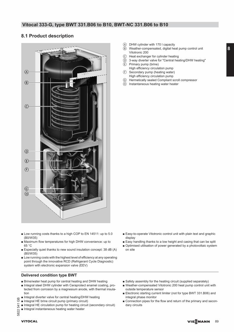
8.1 Product descriptionA DHW cylinder with 170 l capacityB Weather-compensated, digital heat pump control unit
Vitotronic 200C Heat exchanger for cylinder heatingD 3-way diverter valve for "Central heating/DHW heating"E Primary pump (brine)
High efficiency circulation pumpF Secondary pump (heating water)
High efficiency circulation pumpG Hermetically sealed Compliant scroll compressorH Instantaneous heating water heater
■ Low running costs thanks to a high COP to EN 14511: up to 5.0(B0/W35)
■ Maximum flow temperatures for high DHW convenience: up to65 °C
■ Especially quiet thanks to new sound insulation concept: 38 dB (A)(B0/W35)
■ Low running costs with the highest level of efficiency at any operatingpoint through the innovative RCD (Refrigerant Cycle Diagnostic)system with electronic expansion valve (EEV)
■ Easy-to-operate Vitotronic control unit with plain text and graphicdisplay
■ Easy handling thanks to a low height and casing that can be split■ Optimised utilisation of power generated by a photovoltaic system
on site
Delivered condition type BWT■ Brine/water heat pump for central heating and DHW heating■ Integral steel DHW cylinder with Ceraprotect enamel coating, pro-
tected from corrosion by a magnesium anode, with thermal insula-tion
■ Integral diverter valve for central heating/DHW heating■ Integral HE brine circuit pump (primary circuit)■ Integral HE circulation pump for heating circuit (secondary circuit)■ Integral instantaneous heating water heater
■ Safety assembly for the heating circuit (supplied separately)■ Weather-compensated Vitotronic 200 heat pump control unit with
outside temperature sensor■ Electronic starting current limiter (not for type BWT 331.B06) and
integral phase monitor■ Connection pipes for the flow and return of the primary and secon-
dary circuits
Vitocal 333-G, type BWT 331.B06 to B10, BWT-NC 331.B06 to B10
VITOCAL VIESMANN 89
5822
541
GB
8

Delivered condition type BWT-NC■ Brine/water heat pump for central heating and DHW heating■ Integral steel DHW cylinder with Ceraprotect enamel coating, pro-
tected from corrosion by a magnesium anode, with thermal insula-tion
■ Integral diverter valve for central heating/DHW heating■ Integral HE brine circuit pump (primary circuit)■ Integral HE circulation pump for heating circuit (secondary circuit)■ Integral instantaneous heating water heater
■ Safety assembly for the heating circuit (supplied separately)■ Weather-compensated Vitotronic 200 heat pump control unit with
outside temperature sensor■ Integral components for natural cooling■ Electronic starting current limiter (not for type BWT-NC 331.B06) and
integral phase monitor■ Connection pipes for the flow and return of the primary and secon-
dary circuits
Vitocal 333-G, type BWT 331.B06 to B10, BWT-NC 331.B06 to B10 (cont.)
90 VIESMANN VITOCAL
8
5822
541
GB
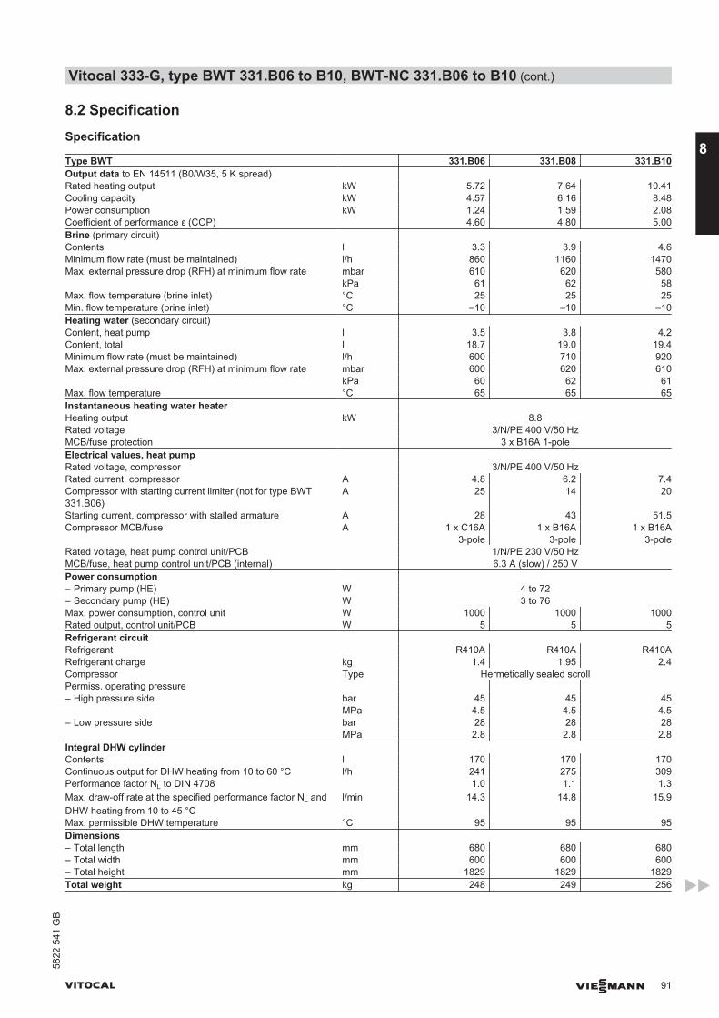
8.2 Specification
Specification
Type BWT 331.B06 331.B08 331.B10Output data to EN 14511 (B0/W35, 5 K spread) Rated heating output kW 5.72 7.64 10.41Cooling capacity kW 4.57 6.16 8.48Power consumption kW 1.24 1.59 2.08Coefficient of performance ε (COP) 4.60 4.80 5.00Brine (primary circuit) Contents l 3.3 3.9 4.6Minimum flow rate (must be maintained) l/h 860 1160 1470Max. external pressure drop (RFH) at minimum flow rate mbar 610 620 580 kPa 61 62 58Max. flow temperature (brine inlet) °C 25 25 25Min. flow temperature (brine inlet) °C –10 –10 –10Heating water (secondary circuit) Content, heat pump l 3.5 3.8 4.2Content, total l 18.7 19.0 19.4Minimum flow rate (must be maintained) l/h 600 710 920Max. external pressure drop (RFH) at minimum flow rate mbar 600 620 610 kPa 60 62 61Max. flow temperature °C 65 65 65Instantaneous heating water heater Heating output kW 8.8Rated voltage 3/N/PE 400 V/50 HzMCB/fuse protection 3 x B16A 1-poleElectrical values, heat pump Rated voltage, compressor 3/N/PE 400 V/50 HzRated current, compressor A 4.8 6.2 7.4Compressor with starting current limiter (not for type BWT331.B06)
A 25 14 20
Starting current, compressor with stalled armature A 28 43 51.5Compressor MCB/fuse A 1 x C16A
3-pole1 x B16A
3-pole1 x B16A
3-poleRated voltage, heat pump control unit/PCB 1/N/PE 230 V/50 HzMCB/fuse, heat pump control unit/PCB (internal) 6.3 A (slow) / 250 VPower consumption – Primary pump (HE) W 4 to 72– Secondary pump (HE) W 3 to 76Max. power consumption, control unit W 1000 1000 1000Rated output, control unit/PCB W 5 5 5Refrigerant circuit Refrigerant R410A R410A R410ARefrigerant charge kg 1.4 1.95 2.4Compressor Type Hermetically sealed scrollPermiss. operating pressure – High pressure side bar 45 45 45 MPa 4.5 4.5 4.5– Low pressure side bar 28 28 28 MPa 2.8 2.8 2.8Integral DHW cylinder Contents l 170 170 170Continuous output for DHW heating from 10 to 60 °C l/h 241 275 309Performance factor NL to DIN 4708 1.0 1.1 1.3Max. draw-off rate at the specified performance factor NL andDHW heating from 10 to 45 °C
l/min 14.3 14.8 15.9
Max. permissible DHW temperature °C 95 95 95Dimensions – Total length mm 680 680 680– Total width mm 600 600 600– Total height mm 1829 1829 1829Total weight kg 248 249 256
Vitocal 333-G, type BWT 331.B06 to B10, BWT-NC 331.B06 to B10 (cont.)
VITOCAL VIESMANN 91
5822
541
GB
8
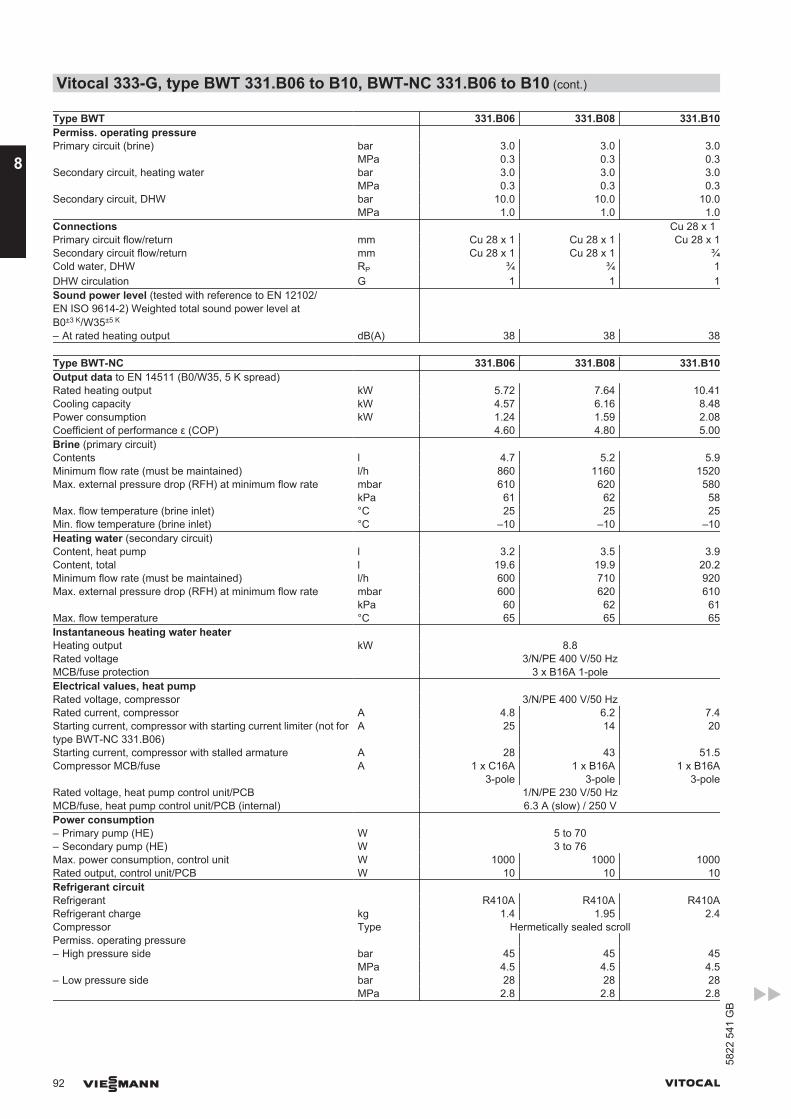
Type BWT 331.B06 331.B08 331.B10Permiss. operating pressure Primary circuit (brine) bar 3.0 3.0 3.0 MPa 0.3 0.3 0.3Secondary circuit, heating water bar 3.0 3.0 3.0 MPa 0.3 0.3 0.3Secondary circuit, DHW bar 10.0 10.0 10.0 MPa 1.0 1.0 1.0Connections Cu 28 x 1Primary circuit flow/return mm Cu 28 x 1 Cu 28 x 1 Cu 28 x 1Secondary circuit flow/return mm Cu 28 x 1 Cu 28 x 1 ¾Cold water, DHW RP ¾ ¾ 1DHW circulation G 1 1 1Sound power level (tested with reference to EN 12102/EN ISO 9614-2) Weighted total sound power level atB0±3 K/W35±5 K
– At rated heating output dB(A) 38 38 38
Type BWT-NC 331.B06 331.B08 331.B10Output data to EN 14511 (B0/W35, 5 K spread) Rated heating output kW 5.72 7.64 10.41Cooling capacity kW 4.57 6.16 8.48Power consumption kW 1.24 1.59 2.08Coefficient of performance ε (COP) 4.60 4.80 5.00Brine (primary circuit) Contents l 4.7 5.2 5.9Minimum flow rate (must be maintained) l/h 860 1160 1520Max. external pressure drop (RFH) at minimum flow rate mbar 610 620 580 kPa 61 62 58Max. flow temperature (brine inlet) °C 25 25 25Min. flow temperature (brine inlet) °C –10 –10 –10Heating water (secondary circuit) Content, heat pump l 3.2 3.5 3.9Content, total l 19.6 19.9 20.2Minimum flow rate (must be maintained) l/h 600 710 920Max. external pressure drop (RFH) at minimum flow rate mbar 600 620 610 kPa 60 62 61Max. flow temperature °C 65 65 65Instantaneous heating water heater Heating output kW 8.8Rated voltage 3/N/PE 400 V/50 HzMCB/fuse protection 3 x B16A 1-poleElectrical values, heat pump Rated voltage, compressor 3/N/PE 400 V/50 HzRated current, compressor A 4.8 6.2 7.4Starting current, compressor with starting current limiter (not fortype BWT-NC 331.B06)
A 25 14 20
Starting current, compressor with stalled armature A 28 43 51.5Compressor MCB/fuse A 1 x C16A
3-pole1 x B16A
3-pole1 x B16A
3-poleRated voltage, heat pump control unit/PCB 1/N/PE 230 V/50 HzMCB/fuse, heat pump control unit/PCB (internal) 6.3 A (slow) / 250 VPower consumption – Primary pump (HE) W 5 to 70– Secondary pump (HE) W 3 to 76Max. power consumption, control unit W 1000 1000 1000Rated output, control unit/PCB W 10 10 10Refrigerant circuit Refrigerant R410A R410A R410ARefrigerant charge kg 1.4 1.95 2.4Compressor Type Hermetically sealed scrollPermiss. operating pressure – High pressure side bar 45 45 45 MPa 4.5 4.5 4.5– Low pressure side bar 28 28 28 MPa 2.8 2.8 2.8
Vitocal 333-G, type BWT 331.B06 to B10, BWT-NC 331.B06 to B10 (cont.)
92 VIESMANN VITOCAL
8
5822
541
GB
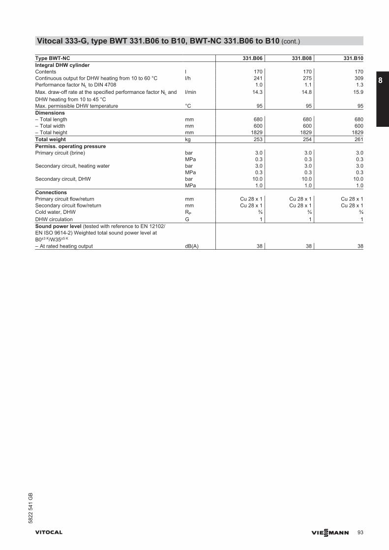
Type BWT-NC 331.B06 331.B08 331.B10Integral DHW cylinder Contents l 170 170 170Continuous output for DHW heating from 10 to 60 °C l/h 241 275 309Performance factor NL to DIN 4708 1.0 1.1 1.3Max. draw-off rate at the specified performance factor NL andDHW heating from 10 to 45 °C
l/min 14.3 14.8 15.9
Max. permissible DHW temperature °C 95 95 95Dimensions – Total length mm 680 680 680– Total width mm 600 600 600– Total height mm 1829 1829 1829Total weight kg 253 254 261Permiss. operating pressure Primary circuit (brine) bar 3.0 3.0 3.0 MPa 0.3 0.3 0.3Secondary circuit, heating water bar 3.0 3.0 3.0 MPa 0.3 0.3 0.3Secondary circuit, DHW bar 10.0 10.0 10.0 MPa 1.0 1.0 1.0Connections Primary circuit flow/return mm Cu 28 x 1 Cu 28 x 1 Cu 28 x 1Secondary circuit flow/return mm Cu 28 x 1 Cu 28 x 1 Cu 28 x 1Cold water, DHW RP ¾ ¾ ¾DHW circulation G 1 1 1Sound power level (tested with reference to EN 12102/EN ISO 9614-2) Weighted total sound power level atB0±3 K/W35±5 K
– At rated heating output dB(A) 38 38 38
Vitocal 333-G, type BWT 331.B06 to B10, BWT-NC 331.B06 to B10 (cont.)
VITOCAL VIESMANN 93
5822
541
GB
8
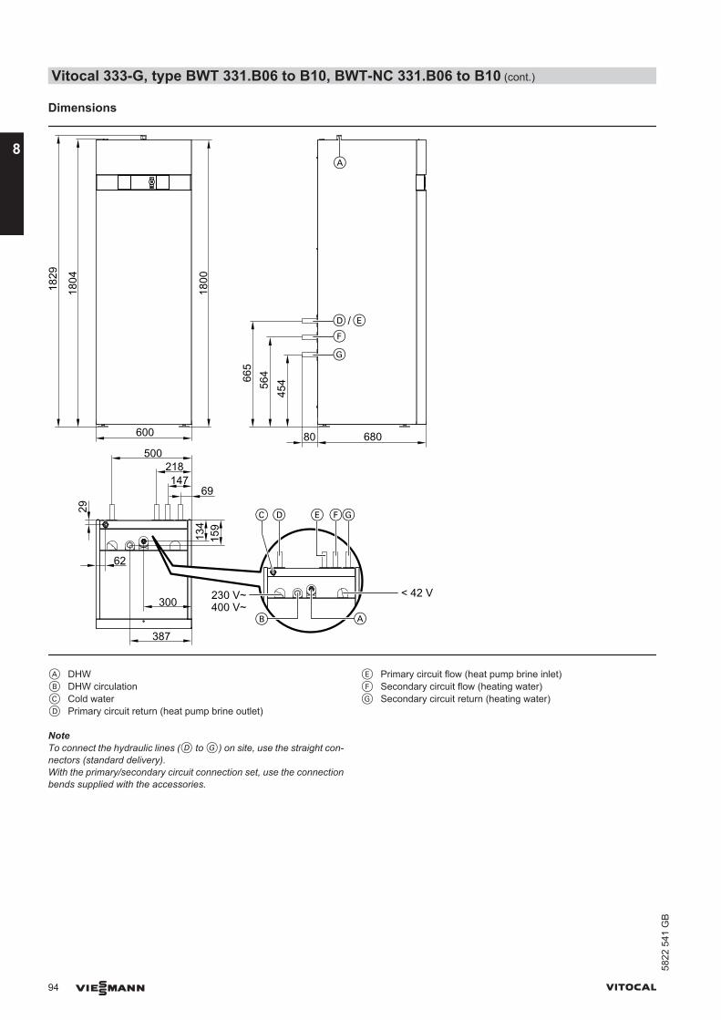
Dimensions
45456
4665
680
1804
1829
600
218147
69
134
159
62
300
387
500
1800
D E
F
G
A
D E GF
AB
C29
/
80
< 42 V230 V~400 V~
A DHWB DHW circulationC Cold waterD Primary circuit return (heat pump brine outlet)
E Primary circuit flow (heat pump brine inlet)F Secondary circuit flow (heating water)G Secondary circuit return (heating water)
NoteTo connect the hydraulic lines (D to G) on site, use the straight con-nectors (standard delivery).With the primary/secondary circuit connection set, use the connectionbends supplied with the accessories.
Vitocal 333-G, type BWT 331.B06 to B10, BWT-NC 331.B06 to B10 (cont.)
94 VIESMANN VITOCAL
8
5822
541
GB
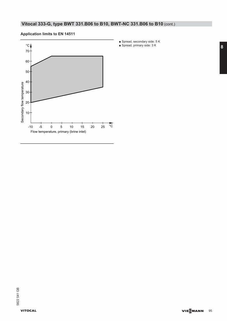
Application limits to EN 14511
Seco
ndar
y flo
w te
mpe
ratu
re
Flow temperature, primary (brine inlet)-5 0 5
°C
°C10 15 20 25-10
10
20
30
40
50
60
70
■ Spread, secondary side: 5 K■ Spread, primary side: 3 K
Vitocal 333-G, type BWT 331.B06 to B10, BWT-NC 331.B06 to B10 (cont.)
VITOCAL VIESMANN 95
5822
541
GB
8
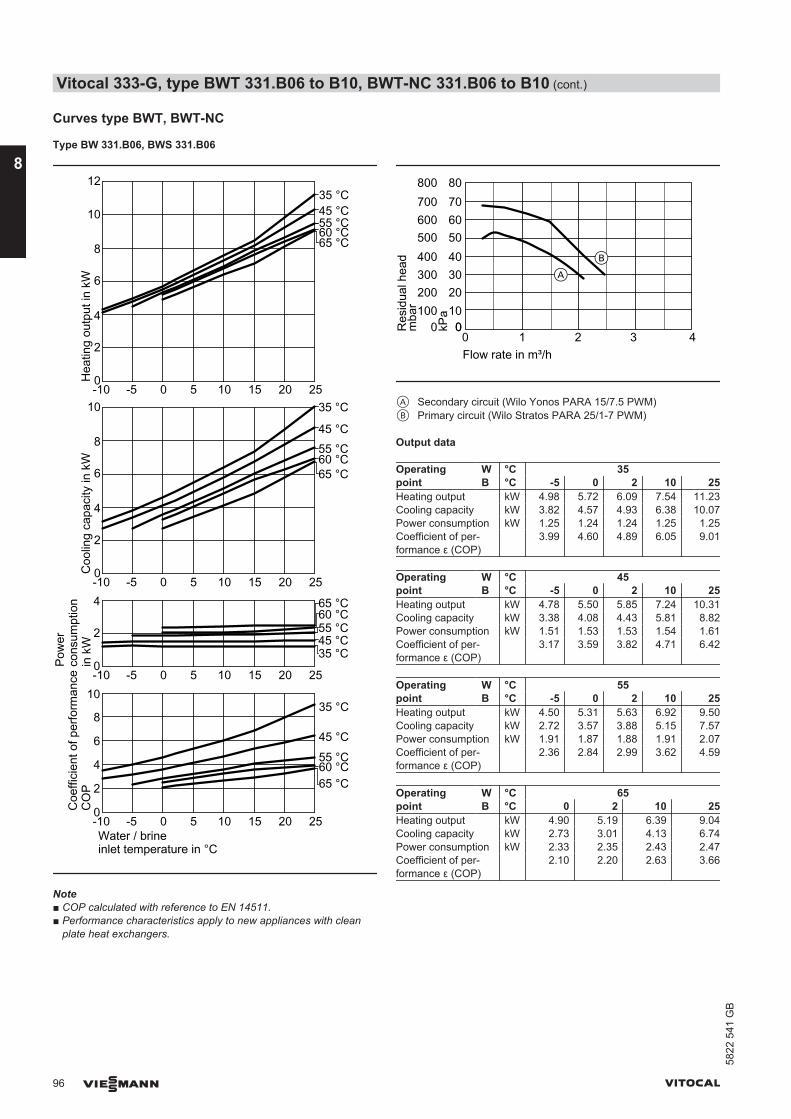
Curves type BWT, BWT-NC
Type BW 331.B06, BWS 331.B06
0
2
-10 -5 0 5 10 15 20 25
-10 -5 0 5 10 15 20 250
2
4
6
8
Water / brineinlet temperature in °C
4
Coe
ffici
ent o
f per
form
ance
CO
PC
oolin
g ca
paci
ty in
kW
Pow
erco
nsum
ptio
n in
kW
Hea
ting
outp
ut in
kW
35 °C
45 °C
55 °C
65 °C
35 °C45 °C55 °C60 °C
0
2
10
-10 -5 0 5 10 15 20 25
4
6
8
0
2
10
-10 -5 0 5 10 15 20 25
12
4
6
8
35 °C
45 °C55 °C60 °C
35 °C45 °C55 °C60 °C
10
65 °C
65 °C
65 °C
60 °C
Note■ COP calculated with reference to EN 14511.■ Performance characteristics apply to new appliances with clean
plate heat exchangers.
0 1 2 3 4Flow rate in m³/h
0100
300
500
700
0
200
400
600
800
Res
idua
l hea
dm
bar 10
30
50
70
0
20
40
60
80
kPa
AB
A Secondary circuit (Wilo Yonos PARA 15/7.5 PWM)B Primary circuit (Wilo Stratos PARA 25/1-7 PWM)
Output data
Operatingpoint
W °C 35B °C -5 0 2 10 25
Heating output kW 4.98 5.72 6.09 7.54 11.23Cooling capacity kW 3.82 4.57 4.93 6.38 10.07Power consumption kW 1.25 1.24 1.24 1.25 1.25Coefficient of per-formance ε (COP)
3.99 4.60 4.89 6.05 9.01
Operatingpoint
W °C 45B °C -5 0 2 10 25
Heating output kW 4.78 5.50 5.85 7.24 10.31Cooling capacity kW 3.38 4.08 4.43 5.81 8.82Power consumption kW 1.51 1.53 1.53 1.54 1.61Coefficient of per-formance ε (COP)
3.17 3.59 3.82 4.71 6.42
Operatingpoint
W °C 55B °C -5 0 2 10 25
Heating output kW 4.50 5.31 5.63 6.92 9.50Cooling capacity kW 2.72 3.57 3.88 5.15 7.57Power consumption kW 1.91 1.87 1.88 1.91 2.07Coefficient of per-formance ε (COP)
2.36 2.84 2.99 3.62 4.59
Operatingpoint
W °C 65B °C 0 2 10 25
Heating output kW 4.90 5.19 6.39 9.04Cooling capacity kW 2.73 3.01 4.13 6.74Power consumption kW 2.33 2.35 2.43 2.47Coefficient of per-formance ε (COP)
2.10 2.20 2.63 3.66
Vitocal 333-G, type BWT 331.B06 to B10, BWT-NC 331.B06 to B10 (cont.)
96 VIESMANN VITOCAL
8
5822
541
GB
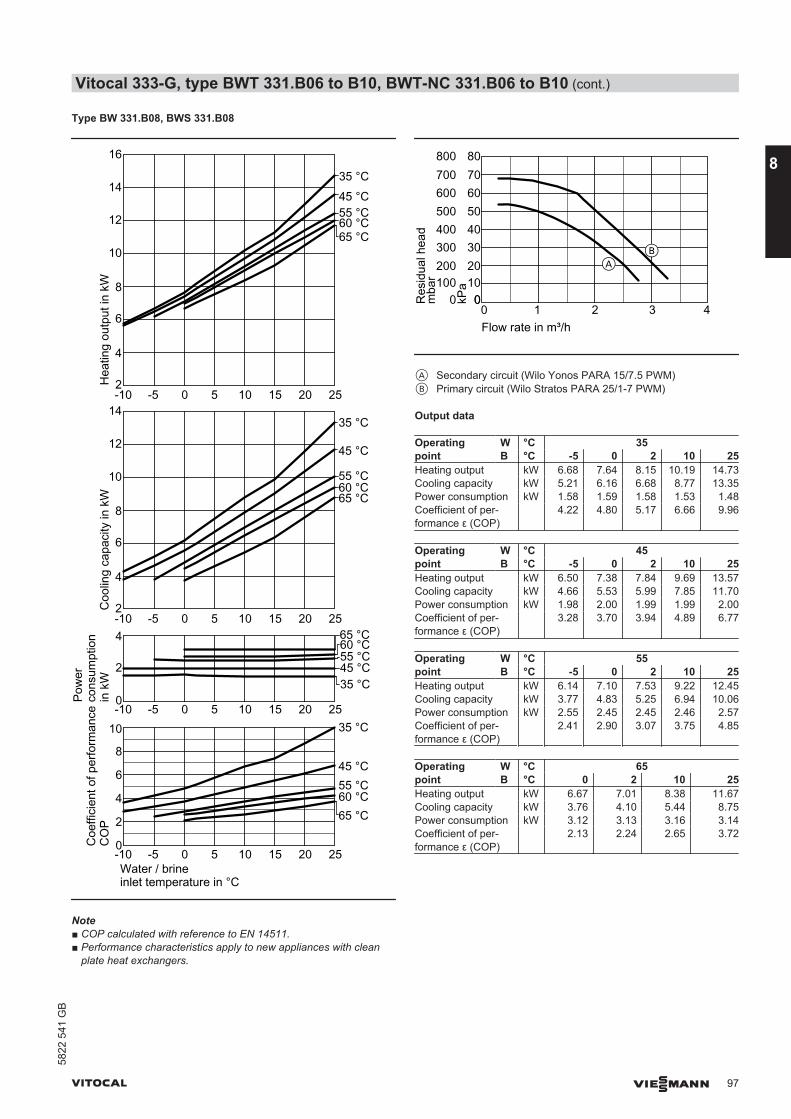
Type BW 331.B08, BWS 331.B08
0
2
-10 -5 0 5 10 15 20 25
-10 -5 0 5 10 15 20 250
2
4
6
8
Water / brineinlet temperature in °C
4
2
10
-10 -5 0 5 10 15 20 25
12
4
6
8
2
10
-10 -5 0 5 10 15 20 25
12
4
6
8
14
Coe
ffici
ent o
f per
form
ance
CO
PC
oolin
g ca
paci
ty in
kW
Pow
erco
nsum
ptio
n in
kW
Hea
ting
outp
ut in
kW
35 °C
45 °C55 °C60 °C
35 °C45 °C55 °C60 °C
35 °C
45 °C
55 °C60 °C
35 °C45 °C55 °C60 °C
10
65 °C
16
14
65 °C
65 °C
65 °C
Note■ COP calculated with reference to EN 14511.■ Performance characteristics apply to new appliances with clean
plate heat exchangers.
0 1 2 3 4Flow rate in m³/h
0100
300
500
700
0
200
400
600
800
Res
idua
l hea
dm
bar 10
30
50
70
0
20
40
60
80
kPa
AB
A Secondary circuit (Wilo Yonos PARA 15/7.5 PWM)B Primary circuit (Wilo Stratos PARA 25/1-7 PWM)
Output data
Operatingpoint
W °C 35B °C -5 0 2 10 25
Heating output kW 6.68 7.64 8.15 10.19 14.73Cooling capacity kW 5.21 6.16 6.68 8.77 13.35Power consumption kW 1.58 1.59 1.58 1.53 1.48Coefficient of per-formance ε (COP)
4.22 4.80 5.17 6.66 9.96
Operatingpoint
W °C 45B °C -5 0 2 10 25
Heating output kW 6.50 7.38 7.84 9.69 13.57Cooling capacity kW 4.66 5.53 5.99 7.85 11.70Power consumption kW 1.98 2.00 1.99 1.99 2.00Coefficient of per-formance ε (COP)
3.28 3.70 3.94 4.89 6.77
Operatingpoint
W °C 55B °C -5 0 2 10 25
Heating output kW 6.14 7.10 7.53 9.22 12.45Cooling capacity kW 3.77 4.83 5.25 6.94 10.06Power consumption kW 2.55 2.45 2.45 2.46 2.57Coefficient of per-formance ε (COP)
2.41 2.90 3.07 3.75 4.85
Operatingpoint
W °C 65B °C 0 2 10 25
Heating output kW 6.67 7.01 8.38 11.67Cooling capacity kW 3.76 4.10 5.44 8.75Power consumption kW 3.12 3.13 3.16 3.14Coefficient of per-formance ε (COP)
2.13 2.24 2.65 3.72
Vitocal 333-G, type BWT 331.B06 to B10, BWT-NC 331.B06 to B10 (cont.)
VITOCAL VIESMANN 97
5822
541
GB
8
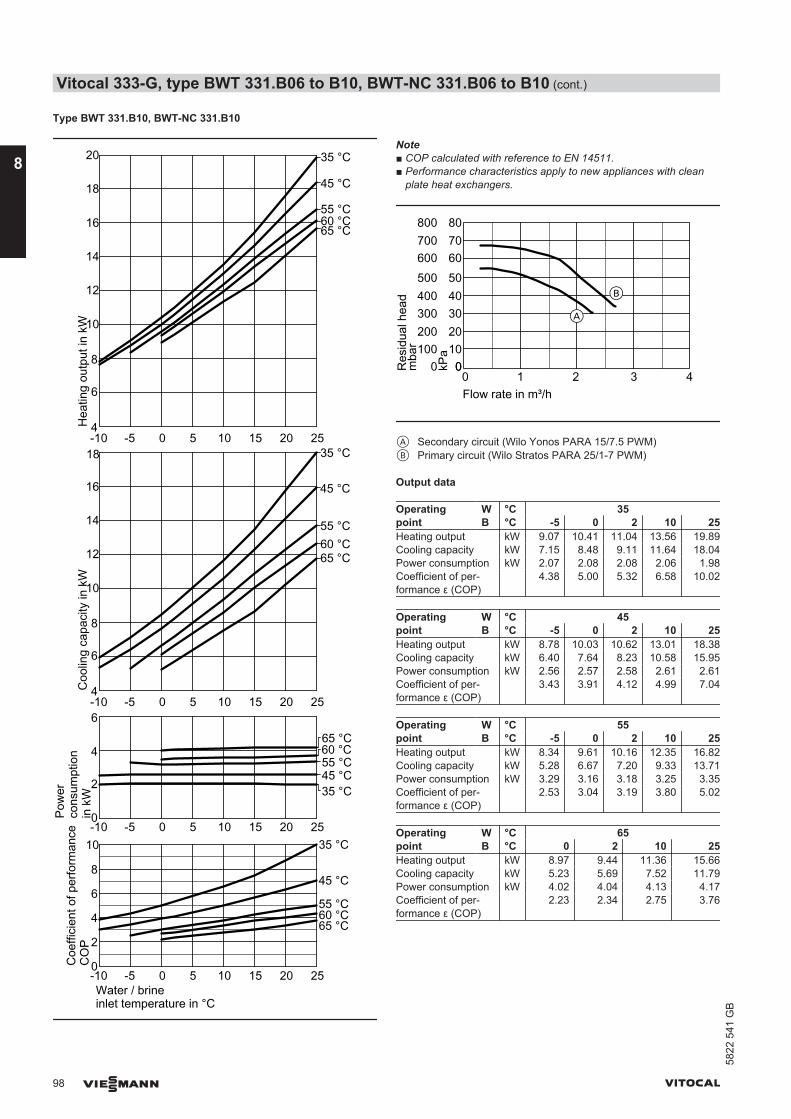
Type BWT 331.B10, BWT-NC 331.B10
0
2
-10 -5 0 5 10 15 20 25
-10 -5 0 5 10 15 20 250
2
4
6
8
Water / brineinlet temperature in °C
4
10
Coe
ffici
ent o
f per
form
ance
CO
PC
oolin
g ca
paci
ty in
kW
Pow
erco
nsum
ptio
n in
kW
Hea
ting
outp
ut in
kW
35 °C
45 °C
55 °C60 °C
35 °C45 °C55 °C60 °C
10
-10 -5 0 5 10 15 20 25
12
4
6
8
14
16
18
20
10
-10 -5 0 5 10 15 20 25
12
4
6
8
14
16
35 °C
45 °C
55 °C60 °C
35 °C
45 °C
55 °C60 °C
18
6
65 °C
65 °C
65 °C
65 °C
Note■ COP calculated with reference to EN 14511.■ Performance characteristics apply to new appliances with clean
plate heat exchangers.
0 1 2 3 4Flow rate in m³/h
0100
300
500
700
0
200
400
600
800
Res
idua
l hea
dm
bar 10
30
50
70
0
20
40
60
80
kPa
A
B
A Secondary circuit (Wilo Yonos PARA 15/7.5 PWM)B Primary circuit (Wilo Stratos PARA 25/1-7 PWM)
Output data
Operatingpoint
W °C 35B °C -5 0 2 10 25
Heating output kW 9.07 10.41 11.04 13.56 19.89Cooling capacity kW 7.15 8.48 9.11 11.64 18.04Power consumption kW 2.07 2.08 2.08 2.06 1.98Coefficient of per-formance ε (COP)
4.38 5.00 5.32 6.58 10.02
Operatingpoint
W °C 45B °C -5 0 2 10 25
Heating output kW 8.78 10.03 10.62 13.01 18.38Cooling capacity kW 6.40 7.64 8.23 10.58 15.95Power consumption kW 2.56 2.57 2.58 2.61 2.61Coefficient of per-formance ε (COP)
3.43 3.91 4.12 4.99 7.04
Operatingpoint
W °C 55B °C -5 0 2 10 25
Heating output kW 8.34 9.61 10.16 12.35 16.82Cooling capacity kW 5.28 6.67 7.20 9.33 13.71Power consumption kW 3.29 3.16 3.18 3.25 3.35Coefficient of per-formance ε (COP)
2.53 3.04 3.19 3.80 5.02
Operatingpoint
W °C 65B °C 0 2 10 25
Heating output kW 8.97 9.44 11.36 15.66Cooling capacity kW 5.23 5.69 7.52 11.79Power consumption kW 4.02 4.04 4.13 4.17Coefficient of per-formance ε (COP)
2.23 2.34 2.75 3.76
Vitocal 333-G, type BWT 331.B06 to B10, BWT-NC 331.B06 to B10 (cont.)
98 VIESMANN VITOCAL
8
5822
541
GB
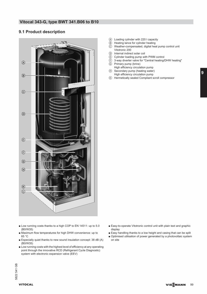
9.1 Product descriptionA Loading cylinder with 220 l capacityB Heating lance for cylinder heatingC Weather-compensated, digital heat pump control unit
Vitotronic 200D Internal indirect solar coilE Cylinder loading pump with PWM controlF 3-way diverter valve for "Central heating/DHW heating"G Primary pump (brine)
High efficiency circulation pumpH Secondary pump (heating water)
High efficiency circulation pumpK Hermetically sealed Compliant scroll compressor
■ Low running costs thanks to a high COP to EN 14511: up to 5.0(B0/W35)
■ Maximum flow temperatures for high DHW convenience: up to65 °C
■ Especially quiet thanks to new sound insulation concept: 38 dB (A)(B0/W35)
■ Low running costs with the highest level of efficiency at any operatingpoint through the innovative RCD (Refrigerant Cycle Diagnostic)system with electronic expansion valve (EEV)
■ Easy-to-operate Vitotronic control unit with plain text and graphicdisplay
■ Easy handling thanks to a low height and casing that can be split■ Optimised utilisation of power generated by a photovoltaic system
on site
Vitocal 343-G, type BWT 341.B06 to B10
VITOCAL VIESMANN 99
5822
541
GB
9

Delivered condition■ Brine/water heat pump for central heating and DHW heating■ Integral steel loading cylinder with Ceraprotect enamel coating, pro-
tected from corrosion by a magnesium anode, with thermal insula-tion
■ Heating lance, solar indirect coil, cylinder loading pump■ Integral diverter valve for central heating/DHW heating■ Integral HE brine circuit pump (primary circuit)■ Integral HE circulation pump for heating circuit (secondary circuit)
■ Integral instantaneous heating water heater■ Safety assembly for the heating circuit (supplied separately)■ Weather-compensated Vitotronic 200 heat pump control unit with
outside temperature sensor■ Electronic starting current limiter (not for type BWT 341.B06) and
integral phase monitor■ Connection pipes for the flow and return of the primary and secon-
dary circuits
Vitocal 343-G, type BWT 341.B06 to B10 (cont.)
100 VIESMANN VITOCAL
9
5822
541
GB
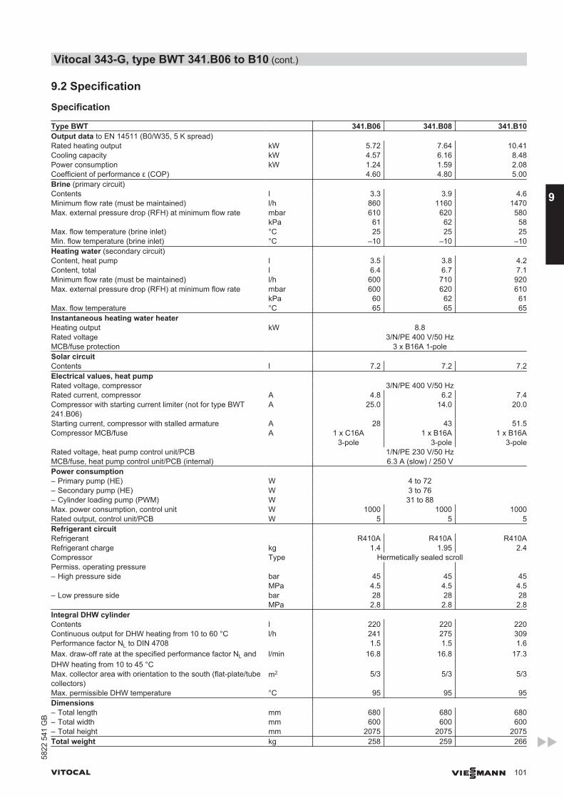
9.2 Specification
Specification
Type BWT 341.B06 341.B08 341.B10Output data to EN 14511 (B0/W35, 5 K spread) Rated heating output kW 5.72 7.64 10.41Cooling capacity kW 4.57 6.16 8.48Power consumption kW 1.24 1.59 2.08Coefficient of performance ε (COP) 4.60 4.80 5.00Brine (primary circuit) Contents l 3.3 3.9 4.6Minimum flow rate (must be maintained) l/h 860 1160 1470Max. external pressure drop (RFH) at minimum flow rate mbar 610 620 580 kPa 61 62 58Max. flow temperature (brine inlet) °C 25 25 25Min. flow temperature (brine inlet) °C –10 –10 –10Heating water (secondary circuit) Content, heat pump l 3.5 3.8 4.2Content, total l 6.4 6.7 7.1Minimum flow rate (must be maintained) l/h 600 710 920Max. external pressure drop (RFH) at minimum flow rate mbar 600 620 610 kPa 60 62 61Max. flow temperature °C 65 65 65Instantaneous heating water heater Heating output kW 8.8Rated voltage 3/N/PE 400 V/50 HzMCB/fuse protection 3 x B16A 1-poleSolar circuit Contents l 7.2 7.2 7.2Electrical values, heat pump Rated voltage, compressor 3/N/PE 400 V/50 HzRated current, compressor A 4.8 6.2 7.4Compressor with starting current limiter (not for type BWT241.B06)
A 25.0 14.0 20.0
Starting current, compressor with stalled armature A 28 43 51.5Compressor MCB/fuse A 1 x C16A
3-pole1 x B16A
3-pole1 x B16A
3-poleRated voltage, heat pump control unit/PCB 1/N/PE 230 V/50 HzMCB/fuse, heat pump control unit/PCB (internal) 6.3 A (slow) / 250 VPower consumption – Primary pump (HE) W 4 to 72– Secondary pump (HE) W 3 to 76– Cylinder loading pump (PWM) W 31 to 88Max. power consumption, control unit W 1000 1000 1000Rated output, control unit/PCB W 5 5 5Refrigerant circuit Refrigerant R410A R410A R410ARefrigerant charge kg 1.4 1.95 2.4Compressor Type Hermetically sealed scrollPermiss. operating pressure – High pressure side bar 45 45 45 MPa 4.5 4.5 4.5– Low pressure side bar 28 28 28 MPa 2.8 2.8 2.8Integral DHW cylinder Contents l 220 220 220Continuous output for DHW heating from 10 to 60 °C l/h 241 275 309Performance factor NL to DIN 4708 1.5 1.5 1.6Max. draw-off rate at the specified performance factor NL andDHW heating from 10 to 45 °C
l/min 16.8 16.8 17.3
Max. collector area with orientation to the south (flat-plate/tubecollectors)
m2 5/3 5/3 5/3
Max. permissible DHW temperature °C 95 95 95Dimensions – Total length mm 680 680 680– Total width mm 600 600 600– Total height mm 2075 2075 2075Total weight kg 258 259 266
Vitocal 343-G, type BWT 341.B06 to B10 (cont.)
VITOCAL VIESMANN 101
5822
541
GB
9
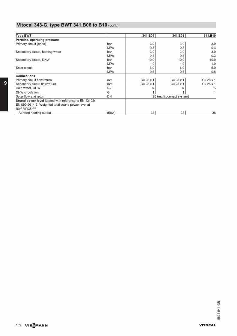
Type BWT 341.B06 341.B08 341.B10Permiss. operating pressure Primary circuit (brine) bar 3.0 3.0 3.0 MPa 0.3 0.3 0.3Secondary circuit, heating water bar 3.0 3.0 3.0 MPa 0.3 0.3 0.3Secondary circuit, DHW bar 10.0 10.0 10.0 MPa 1.0 1.0 1.0Solar circuit bar 6.0 6.0 6.0 MPa 0.6 0.6 0.6Connections Primary circuit flow/return mm Cu 28 x 1 Cu 28 x 1 Cu 28 x 1Secondary circuit flow/return mm Cu 28 x 1 Cu 28 x 1 Cu 28 x 1Cold water, DHW RP ¾ ¾ ¾DHW circulation G 1 1 1Solar flow and return DN 20 (multi connect system)Sound power level (tested with reference to EN 12102/EN ISO 9614-2) Weighted total sound power level atB0±3 K/W35±5 K
– At rated heating output dB(A) 38 38 38
Vitocal 343-G, type BWT 341.B06 to B10 (cont.)
102 VIESMANN VITOCAL
9
5822
541
GB

Dimensions20
47
2075
45456
4665
2075
600 680500
218147
69
29
300
387
134
159
62
D E GF
AB
C
HK
D E
F
G
AHK
29
/
61111
80
< 42 V230 V~400 V~
A DHWB DHW circulationC Cold waterD Primary circuit return (heat pump brine outlet)E Primary circuit flow (heat pump brine inlet)
F Secondary circuit flow (heating water)G Secondary circuit return (heating water)H Solar circuit flowK Solar circuit return
NoteTo connect the hydraulic lines (D to G) on site, use the straight con-nectors (standard delivery).With the primary/secondary circuit connection set, use the connectionbends supplied with the accessories.
Vitocal 343-G, type BWT 341.B06 to B10 (cont.)
VITOCAL VIESMANN 103
5822
541
GB
9
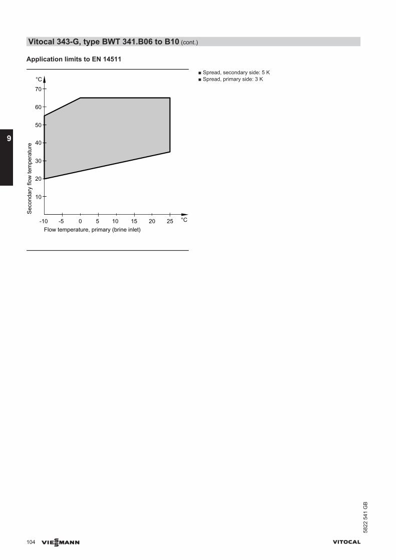
Application limits to EN 14511
Seco
ndar
y flo
w te
mpe
ratu
re
Flow temperature, primary (brine inlet)-5 0 5
°C
°C10 15 20 25-10
10
20
30
40
50
60
70
■ Spread, secondary side: 5 K■ Spread, primary side: 3 K
Vitocal 343-G, type BWT 341.B06 to B10 (cont.)
104 VIESMANN VITOCAL
9
5822
541
GB

Curves type BWT
Type BWT 341.B06
0
2
-10 -5 0 5 10 15 20 25
-10 -5 0 5 10 15 20 250
2
4
6
8
Water / brineinlet temperature in °C
4
Coe
ffici
ent o
f per
form
ance
CO
PC
oolin
g ca
paci
ty in
kW
Pow
erco
nsum
ptio
n in
kW
Hea
ting
outp
ut in
kW
35 °C
45 °C
55 °C
65 °C
35 °C45 °C55 °C60 °C
0
2
10
-10 -5 0 5 10 15 20 25
4
6
8
0
2
10
-10 -5 0 5 10 15 20 25
12
4
6
8
35 °C
45 °C55 °C60 °C
35 °C45 °C55 °C60 °C
10
65 °C
65 °C
65 °C
60 °C
Note■ COP calculated with reference to EN 14511.■ Performance characteristics apply to new appliances with clean
plate heat exchangers.
0 1 2 3 4Flow rate in m³/h
0100
300
500
700
0
200
400
600
800
Res
idua
l hea
dm
bar 10
30
50
70
0
20
40
60
80
kPa
AB
A Secondary circuit (Wilo Yonos PARA 15/7.5 PWM)B Primary circuit (Wilo Stratos PARA 25/1-7 PWM)
Output data
Operatingpoint
W °C 35B °C -5 0 2 10 25
Heating output kW 4.98 5.72 6.09 7.54 11.23Cooling capacity kW 3.82 4.57 4.93 6.38 10.07Power consumption kW 1.25 1.24 1.24 1.25 1.25Coefficient of per-formance ε (COP)
3.99 4.60 4.89 6.05 9.01
Operatingpoint
W °C 45B °C -5 0 2 10 25
Heating output kW 4.78 5.50 5.85 7.24 10.31Cooling capacity kW 3.38 4.08 4.43 5.81 8.82Power consumption kW 1.51 1.53 1.53 1.54 1.61Coefficient of per-formance ε (COP)
3.17 3.59 3.82 4.71 6.42
Operatingpoint
W °C 55B °C -5 0 2 10 25
Heating output kW 4.50 5.31 5.63 6.92 9.50Cooling capacity kW 2.72 3.57 3.88 5.15 7.57Power consumption kW 1.91 1.87 1.88 1.91 2.07Coefficient of per-formance ε (COP)
2.36 2.84 2.99 3.62 4.59
Operatingpoint
W °C 65B °C 0 2 10 25
Heating output kW 4.90 5.19 6.39 9.04Cooling capacity kW 2.73 3.01 4.13 6.74Power consumption kW 2.33 2.35 2.43 2.47Coefficient of per-formance ε (COP)
2.10 2.20 2.63 3.66
Vitocal 343-G, type BWT 341.B06 to B10 (cont.)
VITOCAL VIESMANN 105
5822
541
GB
9

Type BWT 341.B08
0
2
-10 -5 0 5 10 15 20 25
-10 -5 0 5 10 15 20 250
2
4
6
8
Water / brineinlet temperature in °C
4
2
10
-10 -5 0 5 10 15 20 25
12
4
6
8
2
10
-10 -5 0 5 10 15 20 25
12
4
6
8
14
Coe
ffici
ent o
f per
form
ance
CO
PC
oolin
g ca
paci
ty in
kW
Pow
erco
nsum
ptio
n in
kW
Hea
ting
outp
ut in
kW
35 °C
45 °C55 °C60 °C
35 °C45 °C55 °C60 °C
35 °C
45 °C
55 °C60 °C
35 °C45 °C55 °C60 °C
10
65 °C
16
14
65 °C
65 °C
65 °C
Note■ COP calculated with reference to EN 14511.■ Performance characteristics apply to new appliances with clean
plate heat exchangers.
0 1 2 3 4Flow rate in m³/h
0100
300
500
700
0
200
400
600
800
Res
idua
l hea
dm
bar 10
30
50
70
0
20
40
60
80
kPa
AB
A Secondary circuit (Wilo Yonos PARA 15/7.5 PWM)B Primary circuit (Wilo Stratos PARA 25/1-7 PWM)
Output data
Operatingpoint
W °C 35B °C -5 0 2 10 25
Heating output kW 6.68 7.64 8.15 10.19 14.73Cooling capacity kW 5.21 6.16 6.68 8.77 13.35Power consumption kW 1.58 1.59 1.58 1.53 1.48Coefficient of per-formance ε (COP)
4.22 4.80 5.17 6.66 9.96
Operatingpoint
W °C 45B °C -5 0 2 10 25
Heating output kW 6.50 7.38 7.84 9.69 13.57Cooling capacity kW 4.66 5.53 5.99 7.85 11.70Power consumption kW 1.98 2.00 1.99 1.99 2.00Coefficient of per-formance ε (COP)
3.28 3.70 3.94 4.89 6.77
Operatingpoint
W °C 55B °C -5 0 2 10 25
Heating output kW 6.14 7.10 7.53 9.22 12.45Cooling capacity kW 3.77 4.83 5.25 6.94 10.06Power consumption kW 2.55 2.45 2.45 2.46 2.57Coefficient of per-formance ε (COP)
2.41 2.90 3.07 3.75 4.85
Operatingpoint
W °C 65B °C 0 2 10 25
Heating output kW 6.67 7.01 8.38 11.67Cooling capacity kW 3.76 4.10 5.44 8.75Power consumption kW 3.12 3.13 3.16 3.14Coefficient of per-formance ε (COP)
2.13 2.24 2.65 3.72
Vitocal 343-G, type BWT 341.B06 to B10 (cont.)
106 VIESMANN VITOCAL
9
5822
541
GB
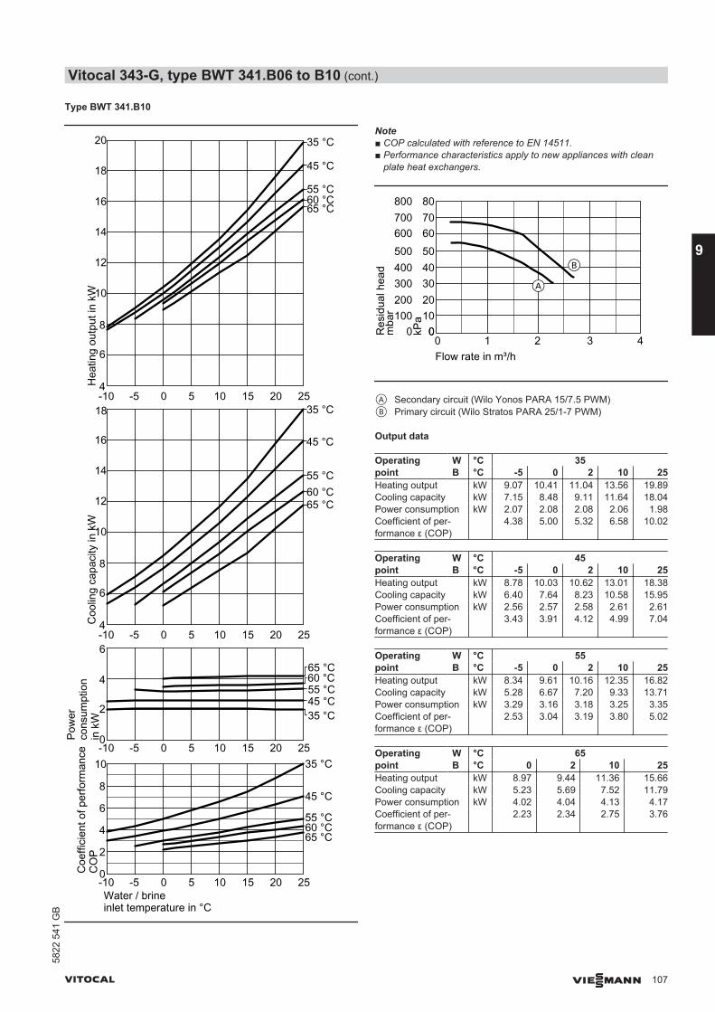
Type BWT 341.B10
0
2
-10 -5 0 5 10 15 20 25
-10 -5 0 5 10 15 20 250
2
4
6
8
Water / brineinlet temperature in °C
4
10
Coe
ffici
ent o
f per
form
ance
CO
PC
oolin
g ca
paci
ty in
kW
Pow
erco
nsum
ptio
n in
kW
Hea
ting
outp
ut in
kW
35 °C
45 °C
55 °C60 °C
35 °C45 °C55 °C60 °C
10
-10 -5 0 5 10 15 20 25
12
4
6
8
14
16
18
20
10
-10 -5 0 5 10 15 20 25
12
4
6
8
14
16
35 °C
45 °C
55 °C60 °C
35 °C
45 °C
55 °C60 °C
18
6
65 °C
65 °C
65 °C
65 °C
Note■ COP calculated with reference to EN 14511.■ Performance characteristics apply to new appliances with clean
plate heat exchangers.
0 1 2 3 4Flow rate in m³/h
0100
300
500
700
0
200
400
600
800
Res
idua
l hea
dm
bar 10
30
50
70
0
20
40
60
80
kPa
A
B
A Secondary circuit (Wilo Yonos PARA 15/7.5 PWM)B Primary circuit (Wilo Stratos PARA 25/1-7 PWM)
Output data
Operatingpoint
W °C 35B °C -5 0 2 10 25
Heating output kW 9.07 10.41 11.04 13.56 19.89Cooling capacity kW 7.15 8.48 9.11 11.64 18.04Power consumption kW 2.07 2.08 2.08 2.06 1.98Coefficient of per-formance ε (COP)
4.38 5.00 5.32 6.58 10.02
Operatingpoint
W °C 45B °C -5 0 2 10 25
Heating output kW 8.78 10.03 10.62 13.01 18.38Cooling capacity kW 6.40 7.64 8.23 10.58 15.95Power consumption kW 2.56 2.57 2.58 2.61 2.61Coefficient of per-formance ε (COP)
3.43 3.91 4.12 4.99 7.04
Operatingpoint
W °C 55B °C -5 0 2 10 25
Heating output kW 8.34 9.61 10.16 12.35 16.82Cooling capacity kW 5.28 6.67 7.20 9.33 13.71Power consumption kW 3.29 3.16 3.18 3.25 3.35Coefficient of per-formance ε (COP)
2.53 3.04 3.19 3.80 5.02
Operatingpoint
W °C 65B °C 0 2 10 25
Heating output kW 8.97 9.44 11.36 15.66Cooling capacity kW 5.23 5.69 7.52 11.79Power consumption kW 4.02 4.04 4.13 4.17Coefficient of per-formance ε (COP)
2.23 2.34 2.75 3.76
Vitocal 343-G, type BWT 341.B06 to B10 (cont.)
VITOCAL VIESMANN 107
5822
541
GB
9
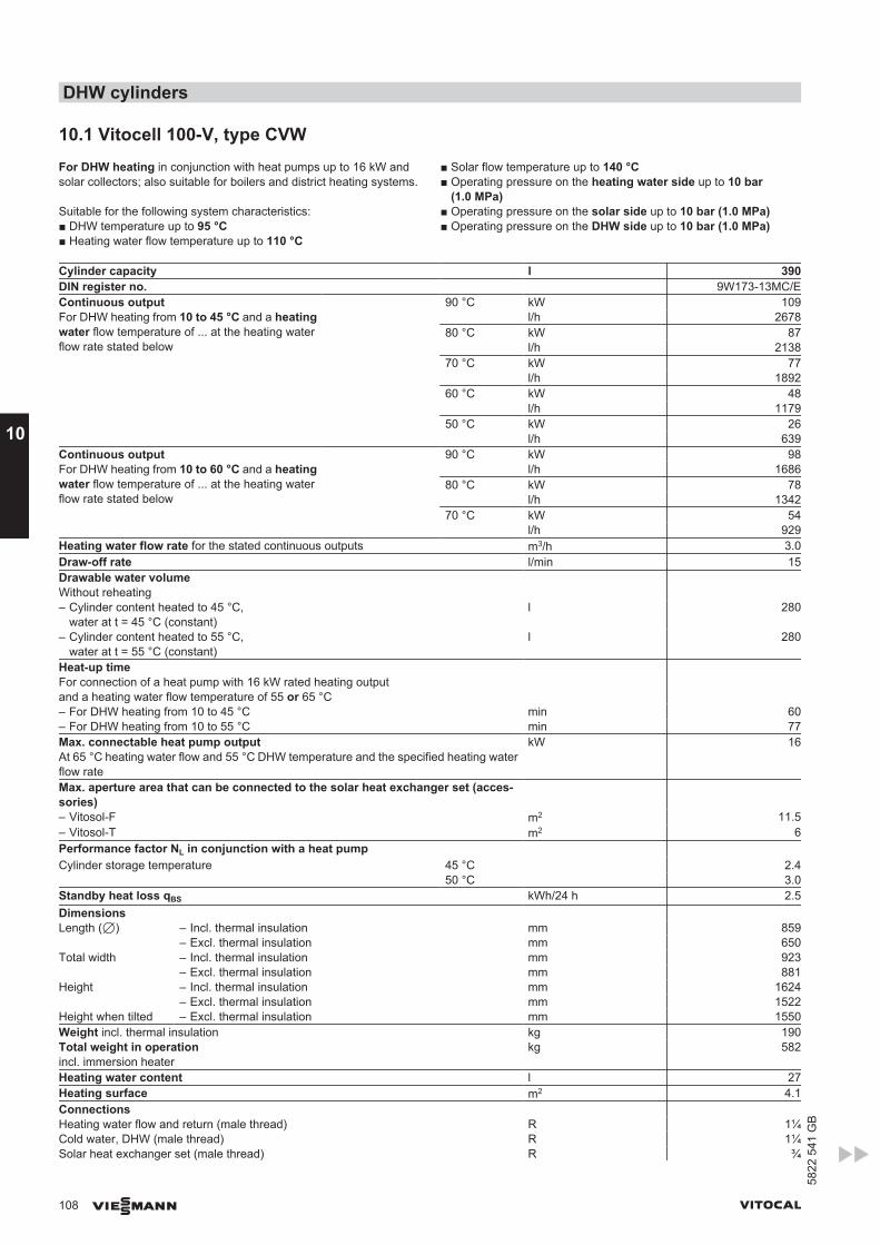
10.1 Vitocell 100-V, type CVWFor DHW heating in conjunction with heat pumps up to 16 kW andsolar collectors; also suitable for boilers and district heating systems.
Suitable for the following system characteristics:■ DHW temperature up to 95 °C■ Heating water flow temperature up to 110 °C
■ Solar flow temperature up to 140 °C■ Operating pressure on the heating water side up to 10 bar
(1.0 MPa)■ Operating pressure on the solar side up to 10 bar (1.0 MPa)■ Operating pressure on the DHW side up to 10 bar (1.0 MPa)
Cylinder capacity l 390DIN register no. 9W173-13MC/EContinuous outputFor DHW heating from 10 to 45 °C and a heatingwater flow temperature of ... at the heating waterflow rate stated below
90 °C kW 109 l/h 2678 80 °C kW 87 l/h 2138 70 °C kW 77 l/h 1892 60 °C kW 48 l/h 1179 50 °C kW 26 l/h 639
Continuous outputFor DHW heating from 10 to 60 °C and a heatingwater flow temperature of ... at the heating waterflow rate stated below
90 °C kW 98 l/h 1686 80 °C kW 78 l/h 1342 70 °C kW 54 l/h 929
Heating water flow rate for the stated continuous outputs m3/h 3.0Draw-off rate l/min 15Drawable water volumeWithout reheating
– Cylinder content heated to 45 °C,water at t = 45 °C (constant)
l 280
– Cylinder content heated to 55 °C,water at t = 55 °C (constant)
l 280
Heat-up timeFor connection of a heat pump with 16 kW rated heating outputand a heating water flow temperature of 55 or 65 °C
– For DHW heating from 10 to 45 °C min 60– For DHW heating from 10 to 55 °C min 77Max. connectable heat pump outputAt 65 °C heating water flow and 55 °C DHW temperature and the specified heating waterflow rate
kW 16
Max. aperture area that can be connected to the solar heat exchanger set (acces-sories)
– Vitosol-F m2 11.5– Vitosol-T m2 6Performance factor NL in conjunction with a heat pump Cylinder storage temperature 45 °C 2.4
50 °C 3.0Standby heat loss qBS kWh/24 h 2.5Dimensions Length (7) – Incl. thermal insulation mm 859
– Excl. thermal insulation mm 650Total width – Incl. thermal insulation mm 923
– Excl. thermal insulation mm 881Height – Incl. thermal insulation mm 1624
– Excl. thermal insulation mm 1522Height when tilted – Excl. thermal insulation mm 1550Weight incl. thermal insulation kg 190Total weight in operationincl. immersion heater
kg 582
Heating water content l 27Heating surface m2 4.1Connections Heating water flow and return (male thread) R 1¼Cold water, DHW (male thread) R 1¼Solar heat exchanger set (male thread) R ¾
DHW cylinders
108 VIESMANN VITOCAL
10
5822
541
GB
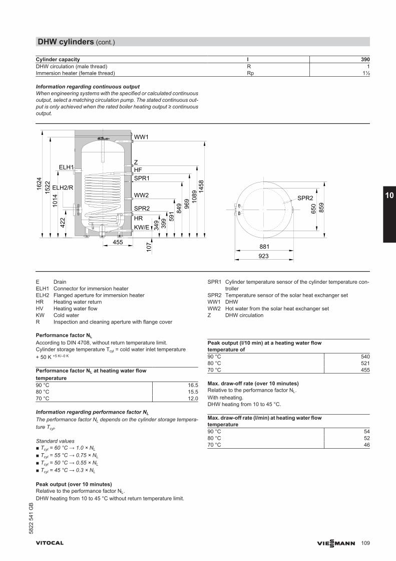
Cylinder capacity l 390DHW circulation (male thread) R 1Immersion heater (female thread) Rp 1½
Information regarding continuous outputWhen engineering systems with the specified or calculated continuousoutput, select a matching circulation pump. The stated continuous out-put is only achieved when the rated boiler heating output ≥ continuousoutput.
107455
349
399 59
1 849 96
9 1089 14
58
422
1014
152216
24
WW1
ZHFSPR1
WW2
SPR2
KW/E
ELH1
HR
ELH2/R
881923
650
859
SPR2
E DrainELH1 Connector for immersion heaterELH2 Flanged aperture for immersion heaterHR Heating water returnHV Heating water flowKW Cold waterR Inspection and cleaning aperture with flange cover
SPR1 Cylinder temperature sensor of the cylinder temperature con-troller
SPR2 Temperature sensor of the solar heat exchanger setWW1 DHWWW2 Hot water from the solar heat exchanger setZ DHW circulation
Performance factor NL
According to DIN 4708, without return temperature limit.Cylinder storage temperature Tcyl = cold water inlet temperature+ 50 K +5 K/–0 K
Performance factor NL at heating water flowtemperature
90 °C 16.580 °C 15.570 °C 12.0
Information regarding performance factor NL
The performance factor NL depends on the cylinder storage tempera-ture Tcyl.
Standard values■ Tcyl = 60 °C → 1.0 × NL
■ Tcyl = 55 °C → 0.75 × NL
■ Tcyl = 50 °C → 0.55 × NL
■ Tcyl = 45 °C → 0.3 × NL
Peak output (over 10 minutes)Relative to the performance factor NL.DHW heating from 10 to 45 °C without return temperature limit.
Peak output (l/10 min) at a heating water flowtemperature of
90 °C 54080 °C 52170 °C 455
Max. draw-off rate (over 10 minutes)Relative to the performance factor NL.With reheating.DHW heating from 10 to 45 °C.
Max. draw-off rate (l/min) at heating water flowtemperature
90 °C 5480 °C 5270 °C 46
DHW cylinders (cont.)
VITOCAL VIESMANN 109
5822
541
GB
10
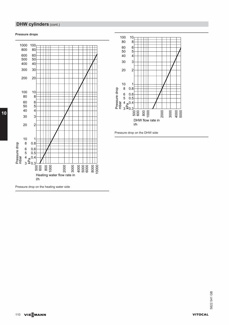
Pressure drops50
060
080
010
00
2000
3000
4000
5000
6000
8000
1000
03
4568
10
20
30
40506080
100
200
300
400500600800
1000
mba
r
0.3
0.40.50.60.8
1
2
3
4568
10
20
30
40506080
100
kPa
Pres
sure
dro
p
Heating water flow rate inl/h
Pressure drop on the heating water side
500
600
800
1000
2000
3000
4000
5000
0.3
0.40.50.60.8
1
2
3
4568
10
kPa
3
4568
10
20
30
40506080
100
mba
rPr
essu
re d
rop
DHW flow rate inl/h
Pressure drop on the DHW side
DHW cylinders (cont.)
110 VIESMANN VITOCAL
10
5822
541
GB

11.1 Overview, installation accessoriesAccessories Part no. Vitocal
200-GBWC201.A06 toA17
300-GBW, BWS,BWC 301.B06 toB17
300-GBW, BWS301.A21 toA45
222-GBWT221.A06 toA10
242-GBWT241.A06 toA10
333-GBWT331.B06 toB10
343-GBWT341.B06 toB10
350-G,typeBW, BWS,BWC 351.A07
350-G,typeBW, BWS351.A18
Ventilation unit, see from page 115Vitovent 300-F – White Z011 432 X X X X– Colour: Vitosilver Z012 121 X X Brine circuit (primary circuit), see from page 117Sensor well set (primary) 7460 714 BW+BWS
(2-stage)
Brine accessory pack: – Up to 13.0 kW*1 ZK00 300 X X X X X X– Up to 25.8 kW*2 ZK00 301 X X X – Brine accessory pack up
to 37 kWZK00 302 BW
(1-stage)BW+BWS(2-stage)
X
Pump set for brine acces-sory pack:
– Up to 13 kW, with HE cir-culation pump Wilo Stra-tos PARA 25/1-7
ZK00 295 BW(1-stage)BW+BWS(2-stage)
– Up to 25.8 kW, with HEcirculation pump WiloStratos PARA 25/1-8
ZK00 296 BW(1-stage)BW+BWS(2-stage)
X
– Up to 37.0 kW, with HEcirculation pump WiloStratos PARA 30/1-12
ZK00 297 BW(1-stage)BW+BWS(2-stage)
X
– Up to 25.8 kW, withstandard circulationpump Wilo TOP S 30/7
ZK00 298 BW(1-stage)BW+BWS(2-stage)
X
– Up to 37.0 kW, withstandard circulationpump Wilo TOP S 30/10
ZK00 299 BW(1-stage)BW+BWS(2-stage)
X
Pressure switch 9532 663 X X X X X X XHE brine circuit pump: – Up to 10 kW, Wilo Stratos
PARA 25/1-77452 617 BW
(1-stage)BW+BWS(2-stage)
– 11 to 17.0 kW, Wilo Stra-tos PARA 25/1-8
7454 536 BW(1-stage)BW+BWS(2-stage)
*1 In conjunction with an ice store system only up to 10 kW is permissible.*2 In conjunction with an ice store system only up to 17 kW is permissible.
Installation accessories
VITOCAL VIESMANN 111
5822
541
GB
11
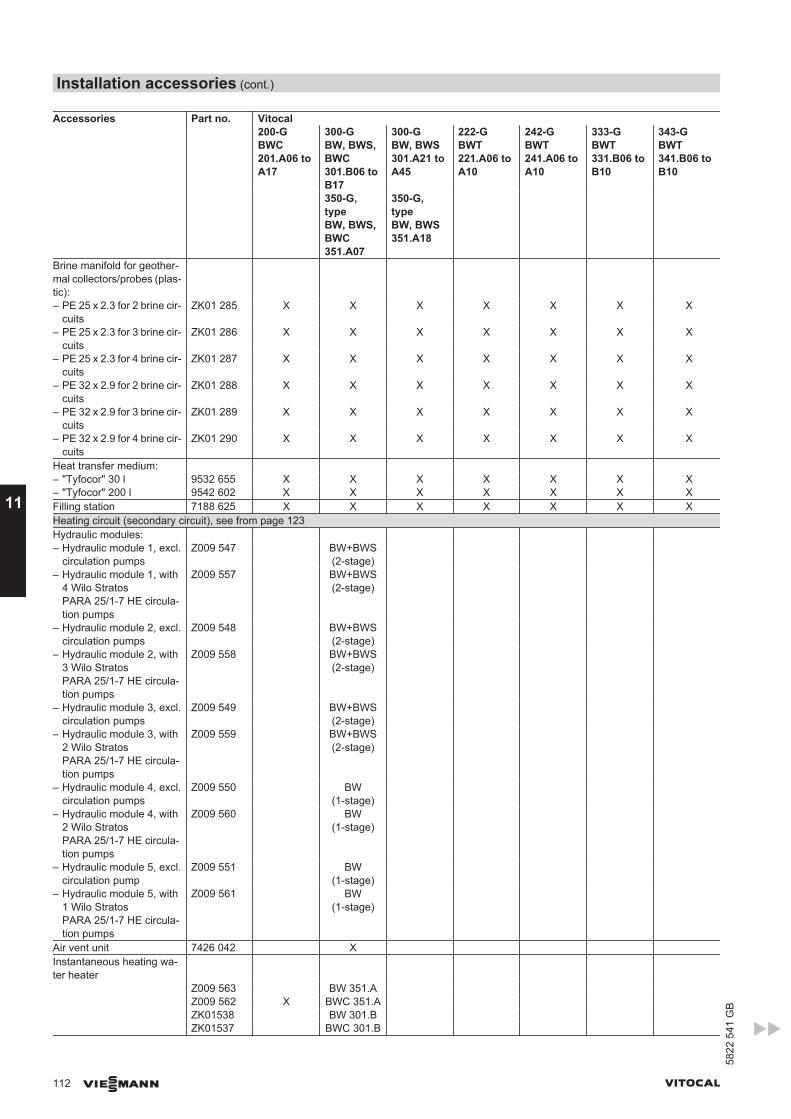
Accessories Part no. Vitocal200-GBWC201.A06 toA17
300-GBW, BWS,BWC 301.B06 toB17
300-GBW, BWS301.A21 toA45
222-GBWT221.A06 toA10
242-GBWT241.A06 toA10
333-GBWT331.B06 toB10
343-GBWT341.B06 toB10
350-G,typeBW, BWS,BWC 351.A07
350-G,typeBW, BWS351.A18
Brine manifold for geother-mal collectors/probes (plas-tic):
– PE 25 x 2.3 for 2 brine cir-cuits
ZK01 285 X X X X X X X
– PE 25 x 2.3 for 3 brine cir-cuits
ZK01 286 X X X X X X X
– PE 25 x 2.3 for 4 brine cir-cuits
ZK01 287 X X X X X X X
– PE 32 x 2.9 for 2 brine cir-cuits
ZK01 288 X X X X X X X
– PE 32 x 2.9 for 3 brine cir-cuits
ZK01 289 X X X X X X X
– PE 32 x 2.9 for 4 brine cir-cuits
ZK01 290 X X X X X X X
Heat transfer medium: – "Tyfocor" 30 l 9532 655 X X X X X X X– "Tyfocor" 200 l 9542 602 X X X X X X XFilling station 7188 625 X X X X X X XHeating circuit (secondary circuit), see from page 123Hydraulic modules: – Hydraulic module 1, excl.
circulation pumpsZ009 547 BW+BWS
(2-stage)
– Hydraulic module 1, with4 Wilo StratosPARA 25/1-7 HE circula-tion pumps
Z009 557 BW+BWS(2-stage)
– Hydraulic module 2, excl.circulation pumps
Z009 548 BW+BWS(2-stage)
– Hydraulic module 2, with3 Wilo StratosPARA 25/1-7 HE circula-tion pumps
Z009 558 BW+BWS(2-stage)
– Hydraulic module 3, excl.circulation pumps
Z009 549 BW+BWS(2-stage)
– Hydraulic module 3, with2 Wilo StratosPARA 25/1-7 HE circula-tion pumps
Z009 559 BW+BWS(2-stage)
– Hydraulic module 4, excl.circulation pumps
Z009 550 BW(1-stage)
– Hydraulic module 4, with2 Wilo StratosPARA 25/1-7 HE circula-tion pumps
Z009 560 BW(1-stage)
– Hydraulic module 5, excl.circulation pump
Z009 551 BW(1-stage)
– Hydraulic module 5, with1 Wilo StratosPARA 25/1-7 HE circula-tion pumps
Z009 561 BW(1-stage)
Air vent unit 7426 042 X Instantaneous heating wa-ter heater
Z009 563 BW 351.A Z009 562 X BWC 351.A ZK01538 BW 301.B ZK01537 BWC 301.B
Installation accessories (cont.)
112 VIESMANN VITOCAL
11
5822
541
GB
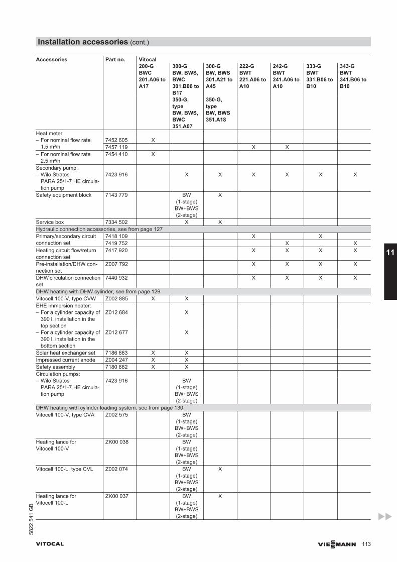
Accessories Part no. Vitocal200-GBWC201.A06 toA17
300-GBW, BWS,BWC 301.B06 toB17
300-GBW, BWS301.A21 toA45
222-GBWT221.A06 toA10
242-GBWT241.A06 toA10
333-GBWT331.B06 toB10
343-GBWT341.B06 toB10
350-G,typeBW, BWS,BWC 351.A07
350-G,typeBW, BWS351.A18
Heat meter – For nominal flow rate
1.5 m³/h7452 605 X 7457 119 X X
– For nominal flow rate2.5 m³/h
7454 410 X
Secondary pump: – Wilo Stratos
PARA 25/1-7 HE circula-tion pump
7423 916 X X X X X X
Safety equipment block 7143 779 BW(1-stage)BW+BWS(2-stage)
X
Service box 7334 502 X X Hydraulic connection accessories, see from page 127Primary/secondary circuitconnection set
7418 109 X X 7419 752 X X
Heating circuit flow/returnconnection set
7417 920 X X X X
Pre-installation/DHW con-nection set
Z007 792 X X X X
DHW circulation connectionset
7440 932 X X X X
DHW heating with DHW cylinder, see from page 129Vitocell 100-V, type CVW Z002 885 X X EHE immersion heater: – For a cylinder capacity of
390 l, installation in thetop section
Z012 684 X
– For a cylinder capacity of390 l, installation in thebottom section
Z012 677 X
Solar heat exchanger set 7186 663 X X Impressed current anode Z004 247 X X Safety assembly 7180 662 X X Circulation pumps: – Wilo Stratos
PARA 25/1-7 HE circula-tion pump
7423 916 BW(1-stage)BW+BWS(2-stage)
DHW heating with cylinder loading system, see from page 130Vitocell 100-V, type CVA Z002 575 BW
(1-stage)BW+BWS(2-stage)
Heating lance forVitocell 100-V
ZK00 038 BW(1-stage)BW+BWS(2-stage)
Vitocell 100-L, type CVL Z002 074 BW(1-stage)BW+BWS(2-stage)
X
Heating lance forVitocell 100-L
ZK00 037 BW(1-stage)BW+BWS(2-stage)
X
Installation accessories (cont.)
VITOCAL VIESMANN 113
5822
541
GB
11
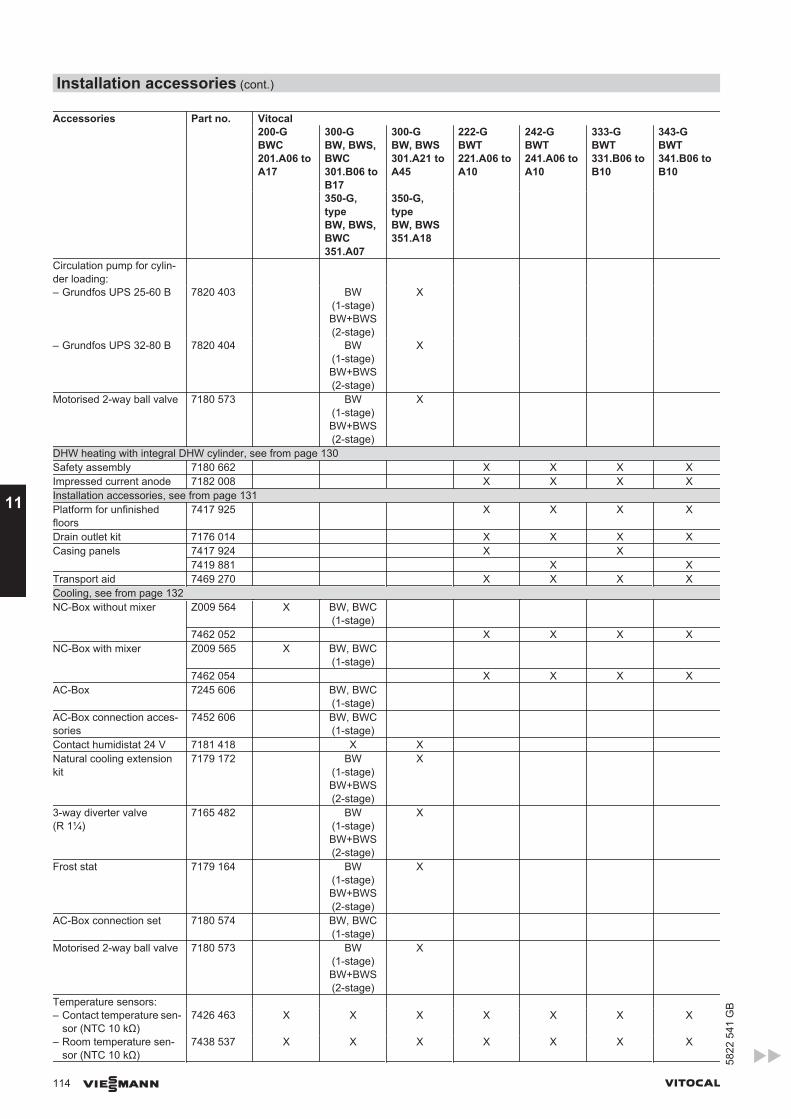
Accessories Part no. Vitocal200-GBWC201.A06 toA17
300-GBW, BWS,BWC 301.B06 toB17
300-GBW, BWS301.A21 toA45
222-GBWT221.A06 toA10
242-GBWT241.A06 toA10
333-GBWT331.B06 toB10
343-GBWT341.B06 toB10
350-G,typeBW, BWS,BWC 351.A07
350-G,typeBW, BWS351.A18
Circulation pump for cylin-der loading:
– Grundfos UPS 25-60 B 7820 403 BW(1-stage)BW+BWS(2-stage)
X
– Grundfos UPS 32-80 B 7820 404 BW(1-stage)BW+BWS(2-stage)
X
Motorised 2-way ball valve 7180 573 BW(1-stage)BW+BWS(2-stage)
X
DHW heating with integral DHW cylinder, see from page 130Safety assembly 7180 662 X X X XImpressed current anode 7182 008 X X X XInstallation accessories, see from page 131Platform for unfinishedfloors
7417 925 X X X X
Drain outlet kit 7176 014 X X X XCasing panels 7417 924 X X
7419 881 X XTransport aid 7469 270 X X X XCooling, see from page 132NC-Box without mixer Z009 564 X BW, BWC
(1-stage)
7462 052 X X X XNC-Box with mixer Z009 565 X BW, BWC
(1-stage)
7462 054 X X X XAC-Box 7245 606 BW, BWC
(1-stage)
AC-Box connection acces-sories
7452 606 BW, BWC(1-stage)
Contact humidistat 24 V 7181 418 X X Natural cooling extensionkit
7179 172 BW(1-stage)BW+BWS(2-stage)
X
3-way diverter valve(R 1¼)
7165 482 BW(1-stage)BW+BWS(2-stage)
X
Frost stat 7179 164 BW(1-stage)BW+BWS(2-stage)
X
AC-Box connection set 7180 574 BW, BWC(1-stage)
Motorised 2-way ball valve 7180 573 BW(1-stage)BW+BWS(2-stage)
X
Temperature sensors: – Contact temperature sen-
sor (NTC 10 kΩ)7426 463 X X X X X X X
– Room temperature sen-sor (NTC 10 kΩ)
7438 537 X X X X X X X
Installation accessories (cont.)
114 VIESMANN VITOCAL
11
5822
541
GB
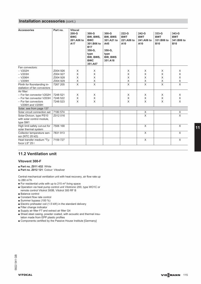
Accessories Part no. Vitocal200-GBWC201.A06 toA17
300-GBW, BWS,BWC 301.B06 toB17
300-GBW, BWS301.A21 toA45
222-GBWT221.A06 toA10
242-GBWT241.A06 toA10
333-GBWT331.B06 toB10
343-GBWT341.B06 toB10
350-G,typeBW, BWS,BWC 351.A07
350-G,typeBW, BWS351.A18
Fan convectors: – V202H Z004 926 X X X X X X– V203H Z004 927 X X X X X X– V206H Z004 928 X X X X X X– V209H Z004 929 X X X X X XPlinth for floorstanding in-stallation of fan convectors
7267 205 X X X X X X
Air filter: – For fan convector V202H 7248 521 X X X X X X– For fan convector V203H 7248 522 X X X X X X– For fan convectors
V206H and V209H7248 523 X X X X X X
Solar, see from page 137Solar circuit connection set 7180 574 X XSolar-Divicon, type PS10with solar control module,type SM1
Z012 016 X X
High limit safety cut-out forsolar thermal system
7506 168 X X
Collector temperature sen-sor (NTC 20 kΩ)
7831 913 X X
Heat transfer medium "Ty-focor LS" 25 l
7159 727 X X
11.2 Ventilation unit
Vitovent 300-F■ Part no. Z011 432: White■ Part no. Z012 121: Colour: Vitosilver
Central mechanical ventilation unit with heat recovery, air flow rate upto 280 m3/h■ For residential units with up to 215 m2 living space■ Operation via heat pump control unit Vitotronic 200, type WO1C or
remote control Vitotrol 300B, Vitotrol 300 RF B■ Balance control■ Constant flow rate control■ Summer bypass (100 %)■ Electric preheater coil (1.5 kW) in the standard delivery■ Filter change indicator■ Supply air filter F7 and extract air filter G4■ Sheet steel casing, powder coated, with acoustic and thermal insu-
lation made from EPP plastic profiles■ Components certified by the Passive House Institute [Germany]
Installation accessories (cont.)
VITOCAL VIESMANN 115
5822
541
GB
11
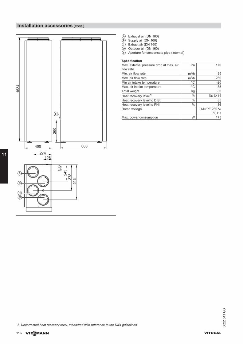
400 680
126274
260
108
243
378
513
1534
A
B
CD
E
A Exhaust air (DN 160)B Supply air (DN 160)C Extract air (DN 160)D Outdoor air (DN 160)E Aperture for condensate pipe (internal)
SpecificationMax. external pressure drop at max. airflow rate
Pa 170
Min. air flow rate m3/h 85Max. air flow rate m3/h 280Min air intake temperature °C -20Max. air intake temperature °C 35Total weight kg 80Heat recovery level*3 % Up to 98Heat recovery level to DIBt % 85Heat recovery level to PHI % 86Rated voltage 1/N/PE 230 V/
50 HzMax. power consumption W 175
*3 Uncorrected heat recovery level, measured with reference to the DIBt guidelines
Installation accessories (cont.)
116 VIESMANN VITOCAL
11
5822
541
GB
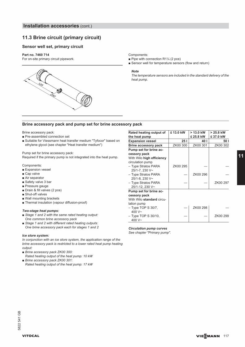
11.3 Brine circuit (primary circuit)
Sensor well set, primary circuit
Part no. 7460 714For on-site primary circuit pipework.
125
250
Components:■ Pipe with connection R1¼ (2 pce)■ Sensor well for temperature sensors (flow and return)
NoteThe temperature sensors are included in the standard delivery of theheat pump.
Brine accessory pack and pump set for brine accessory pack
Brine accessory pack:■ Pre-assembled connection set■ Suitable for Viessmann heat transfer medium "Tyfocor" based on
ethylene glycol (see chapter "Heat transfer medium")
Pump set for brine accessory pack:Required if the primary pump is not integrated into the heat pump.
Components:■ Expansion vessel■ Cap valve■ Air separator■ Safety valve 3 bar■ Pressure gauge■ Drain & fill valves (2 pce)■ Shut-off valves■ Wall mounting brackets■ Thermal insulation (vapour diffusion-proof)
Two-stage heat pumps:■ Stage 1 and 2 with the same rated heating output:
One common brine accessory pack■ Stage 1 and 2 with different rated heating outputs:
One brine accessory pack each for stages 1 and 2
Ice store system:In conjunction with an ice store system, the application range of thebrine accessory pack is restricted to a lower rated heat pump heatingoutput:■ Brine accessory pack ZK00 300:
Rated heating output of the heat pump: 10 kW■ Brine accessory pack ZK00 301:
Rated heating output of the heat pump: 17 kW
Rated heating output ofthe heat pump
≤ 13.0 kW > 13.0 kW≤ 25.8 kW
> 25.8 kW≤ 37.0 kW
Expansion vessel 25 l 40 l 50 lBrine accessory pack ZK00 300 ZK00 301 ZK00 302Pump set for brine ac-cessory packWith Wilo high efficiencycirculation pump
– Type Stratos PARA25/1-7, 230 V~
ZK00 295 — —
– Type Stratos PARA25/1-8, 230 V~
— ZK00 296 —
– Type Stratos PARA25/1-12, 230 V~
— — ZK00 297
Pump set for brine ac-cessory packWith Wilo standard circu-lation pump
– Type TOP S 30/7,400 V~
— ZK00 298 —
– Type TOP S 30/10,400 V~
— — ZK00 299
Circulation pump curvesSee chapter "Primary pump".
Installation accessories (cont.)
VITOCAL VIESMANN 117
5822
541
GB
11
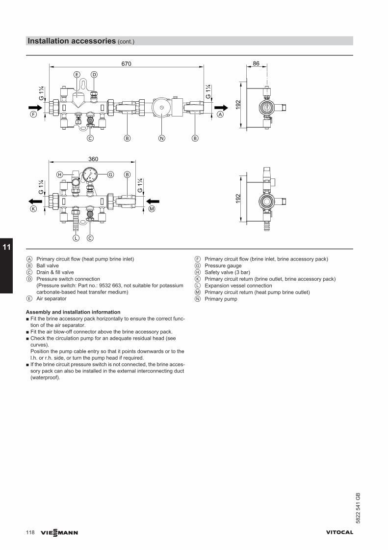
86
192
192
F
K
A
M
L C
B
B
C
GH
E D
B
G 1
¼
G 1
¼
G 1
¼G
1¼
360
670
N
A Primary circuit flow (heat pump brine inlet)B Ball valveC Drain & fill valveD Pressure switch connection
(Pressure switch: Part no.: 9532 663, not suitable for potassiumcarbonate-based heat transfer medium)
E Air separator
F Primary circuit flow (brine inlet, brine accessory pack)G Pressure gaugeH Safety valve (3 bar)K Primary circuit return (brine outlet, brine accessory pack)L Expansion vessel connectionM Primary circuit return (heat pump brine outlet)N Primary pump
Assembly and installation information■ Fit the brine accessory pack horizontally to ensure the correct func-
tion of the air separator.■ Fit the air blow-off connector above the brine accessory pack.■ Check the circulation pump for an adequate residual head (see
curves).Position the pump cable entry so that it points downwards or to thel.h. or r.h. side, or turn the pump head if required.
■ If the brine circuit pressure switch is not connected, the brine acces-sory pack can also be installed in the external interconnecting duct(waterproof).
Installation accessories (cont.)
118 VIESMANN VITOCAL
11
5822
541
GB
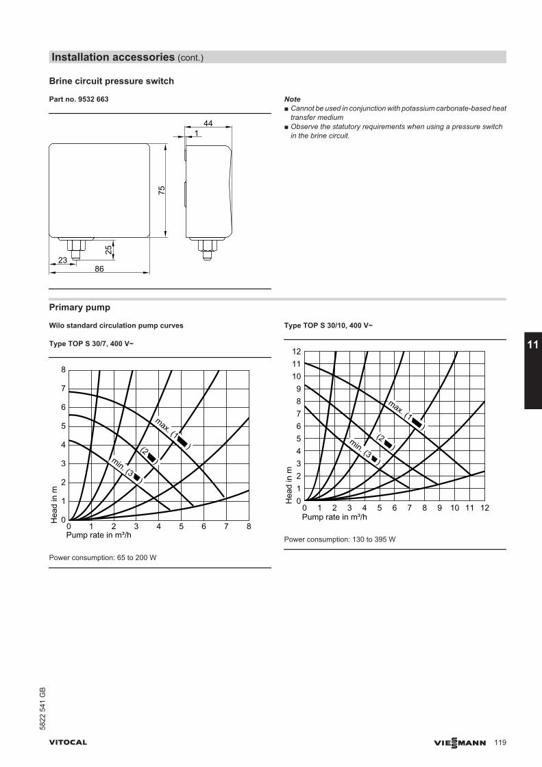
Brine circuit pressure switch
Part no. 9532 663
441
23
75
86
25Note■ Cannot be used in conjunction with potassium carbonate-based heat
transfer medium■ Observe the statutory requirements when using a pressure switch
in the brine circuit.
Primary pump
Wilo standard circulation pump curves
Type TOP S 30/7, 400 V~
(2 )min. (3 )
Pump rate in m³/h0 1 2 3 4 5 6H
ead
in m
0
1
2
3
4
5
6
7
8
87
max. (1 )
Power consumption: 65 to 200 W
Type TOP S 30/10, 400 V~
(2 )min. (3 )
Pump rate in m³/h0 1 2 3 4 5 6
Hea
d in
m
012345678
87
max. (1 )
9 10 11 12
9101112
Power consumption: 130 to 395 W
Installation accessories (cont.)
VITOCAL VIESMANN 119
5822
541
GB
11
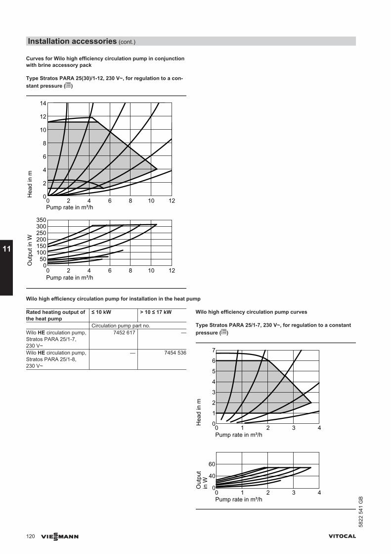
Curves for Wilo high efficiency circulation pump in conjunctionwith brine accessory pack
Type Stratos PARA 25(30)/1-12, 230 V~, for regulation to a con-stant pressure ( )
0 2 4 6 8 10 12
0 2 4 6 8 10 12
0
2
4
6
8
10
12
14
500
150200250300350
100
Pump rate in m³/h
Pump rate in m³/h
Hea
d in
mO
utpu
t in
W
Wilo high efficiency circulation pump for installation in the heat pump
Rated heating output ofthe heat pump
≤ 10 kW > 10 ≤ 17 kW
Circulation pump part no.Wilo HE circulation pump,Stratos PARA 25/1-7,230 V~
7452 617 —
Wilo HE circulation pump,Stratos PARA 25/1-8,230 V~
— 7454 536
Wilo high efficiency circulation pump curves
Type Stratos PARA 25/1-7, 230 V~, for regulation to a constantpressure ( )
0
1
2
4
3
5
6
7
0 1 2 3 4
Hea
d in
m
Pump rate in m³/h
0 1 2 3 4Pump rate in m³/h
0
40
60
Out
put
in W
Installation accessories (cont.)
120 VIESMANN VITOCAL
11
5822
541
GB
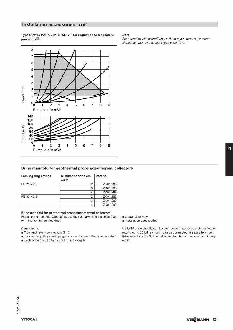
Type Stratos PARA 25/1-8, 230 V~, for regulation to a constantpressure ( )
0 1 2 3 4 5 6 7 8 9
0 1 2 3 4 5 6 7 8 9Pump rate in m³/h
Pump rate in m³/h
020406080
100120140
0
1
2
3
4
5
6
7
8
Hea
d in
mO
utpu
t in
W
NoteFor operation with water/Tyfocor, the pump output supplementsshould be taken into account (see page 167).
Brine manifold for geothermal probes/geothermal collectors
Locking ring fittings Number of brine cir-cuits
Part no.
PE 25 x 2.3 2 ZK01 2853 ZK01 2864 ZK01 287
PE 32 x 2.9 2 ZK01 2883 ZK01 2894 ZK01 290
Brine manifold for geothermal probes/geothermal collectorsPlastic brine manifold. Can be fitted to the house wall, in the cellar ductor in the central service duct.
Components:■ Flow and return connectors G 1½■ Locking ring fittings with plug-in connection onto the brine manifold■ Each brine circuit can be shut off individually
■ 2 drain & fill valves■ Installation accessories
Up to 10 brine circuits can be connected in series to a single flow orreturn; up to 20 brine circuits can be connected in a parallel circuit.Brine manifolds for 2, 3 and 4 brine circuits can be combined in anyorder.
Installation accessories (cont.)
VITOCAL VIESMANN 121
5822
541
GB
11
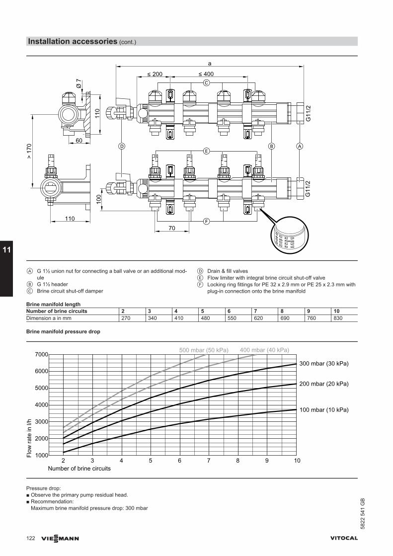
a
200 400
110
Ø 7
60
> 17
0
11070
100
B
C
E
F
D A
G11
/2G
11/2
A G 1½ union nut for connecting a ball valve or an additional mod-ule
B G 1½ headerC Brine circuit shut-off damper
D Drain & fill valvesE Flow limiter with integral brine circuit shut-off valveF Locking ring fittings for PE 32 x 2.9 mm or PE 25 x 2.3 mm with
plug-in connection onto the brine manifold
Brine manifold lengthNumber of brine circuits 2 3 4 5 6 7 8 9 10Dimension a in mm 270 340 410 480 550 620 690 760 830
Brine manifold pressure drop
1000
7000
2000
3000
4000
5000
6000
2 3 4 5 6 7 8 9 10Number of brine circuits
Flow
rate
in l/
h
500 mbar (50 kPa) 400 mbar (40 kPa)
300 mbar (30 kPa)
200 mbar (20 kPa)
100 mbar (10 kPa)
Pressure drop:■ Observe the primary pump residual head.■ Recommendation:
Maximum brine manifold pressure drop: 300 mbar
Installation accessories (cont.)
122 VIESMANN VITOCAL
11
5822
541
GB

Connection versions
RL
VL41 2 3
14 3 2
Example for 4 brine circuits in series
RL Brine returnVL Brine flow
41 2 3
14 3 2
85 6 7
58 7 6RL
VL
Example for 8 brine circuits in parallel
RL Brine returnVL Brine flow
Heat transfer medium "Tyfocor"■ 30 l in a disposable container
Part no. 9532 655■ 200 l in a disposable container
Part no. 9542 602
Light green ready mixed medium for the primary circuit, down to–19 °C, based on ethylene glycol with corrosion inhibitors.
Filling station
Part no. 7188 625For filling the primary circuit.
Components:■ Self-priming impeller pump (30 l/min)■ Dirt filter, inlet side
■ Hose, inlet side (0.5 m)■ Connection hose (2 pce, each 2.5 m)■ Packing crate (can be used as flushing tank)
11.4 Heating circuit (secondary circuit)
Hydraulic modules■ Prefabricated hydraulic connecting kit.■ For mono mode/mono energetic systems with DHW heating, with or
without heating water buffer cylinder.■ Can be used as a connection module in cascade systems.
Components:■ Primary circuit connection lines■ Heating circuit connection lines■ DHW connection lines
■ Connection for further on-site pipes 1¼ (male)■ Wall mounting bracket■ Thermal insulation■ Shut-off valve■ Connection pipes■ Safety valve (3 bar, 1 pce)■ Pressure gauge (1 pce)■ Subject to part no., with or without circulation pump
Hydraulic modules for single stage heat pumps
Hydraulic module 4 Hydraulic module 5Heating X XDHW heating X — Hydraulic module part no.Without circulation pump Z009 550 Z009 551With Wilo high efficiency circulation pump,type Stratos Para 25/1-7, 230 V~
Z009 560With 2 circulation pumps
Z009 561With 1 circulation pump
Circulation pump curvesSee chapter "Secondary pump".
Installation accessories (cont.)
VITOCAL VIESMANN 123
5822
541
GB
11
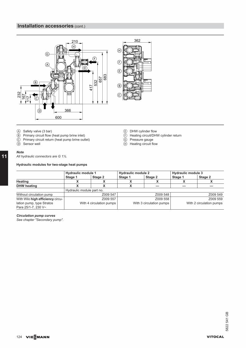
11716
7232
417 53
2 657 68
3
210
366
600
362
D
C
B
AE
F
H
B
F
H
E
C
G
A Safety valve (3 bar)B Primary circuit flow (heat pump brine inlet)C Primary circuit return (heat pump brine outlet)D Sensor well
E DHW cylinder flowF Heating circuit/DHW cylinder returnG Pressure gaugeH Heating circuit flow
NoteAll hydraulic connectors are G 1½.
Hydraulic modules for two-stage heat pumps
Hydraulic module 1 Hydraulic module 2 Hydraulic module 3Stage 1 Stage 2 Stage 1 Stage 2 Stage 1 Stage 2
Heating X X X X X XDHW heating X X X — — — Hydraulic module part no.Without circulation pump Z009 547 Z009 548 Z009 549With Wilo high efficiency circu-lation pump, type StratosPara 25/1-7, 230 V~
Z009 557With 4 circulation pumps
Z009 558With 3 circulation pumps
Z009 559With 2 circulation pumps
Circulation pump curvesSee chapter "Secondary pump".
Installation accessories (cont.)
124 VIESMANN VITOCAL
11
5822
541
GB
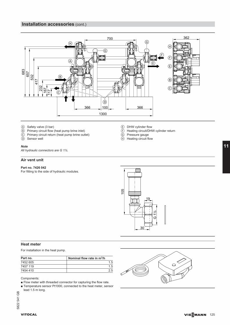
11716723
241
753265
7683
366
1300
C
D
100 366
700
B
A
362H
G
C
B
E
F
HG
F
E
A Safety valve (3 bar)B Primary circuit flow (heat pump brine inlet)C Primary circuit return (heat pump brine outlet)D Sensor well
E DHW cylinder flowF Heating circuit/DHW cylinder returnG Pressure gaugeH Heating circuit flow
NoteAll hydraulic connectors are G 1½.
Air vent unit
Part no. 7426 042For fitting to the side of hydraulic modules.
19
30
105
G 1
½
Heat meterFor installation in the heat pump.
Part no. Nominal flow rate in m3/h7452 605 1.57457 119 1.57454 410 2.5
Components:■ Flow meter with threaded connector for capturing the flow rate.■ Temperature sensor Pt1000, connected to the heat meter, sensor
lead 1.5 m long.
Installation accessories (cont.)
VITOCAL VIESMANN 125
5822
541
GB
11
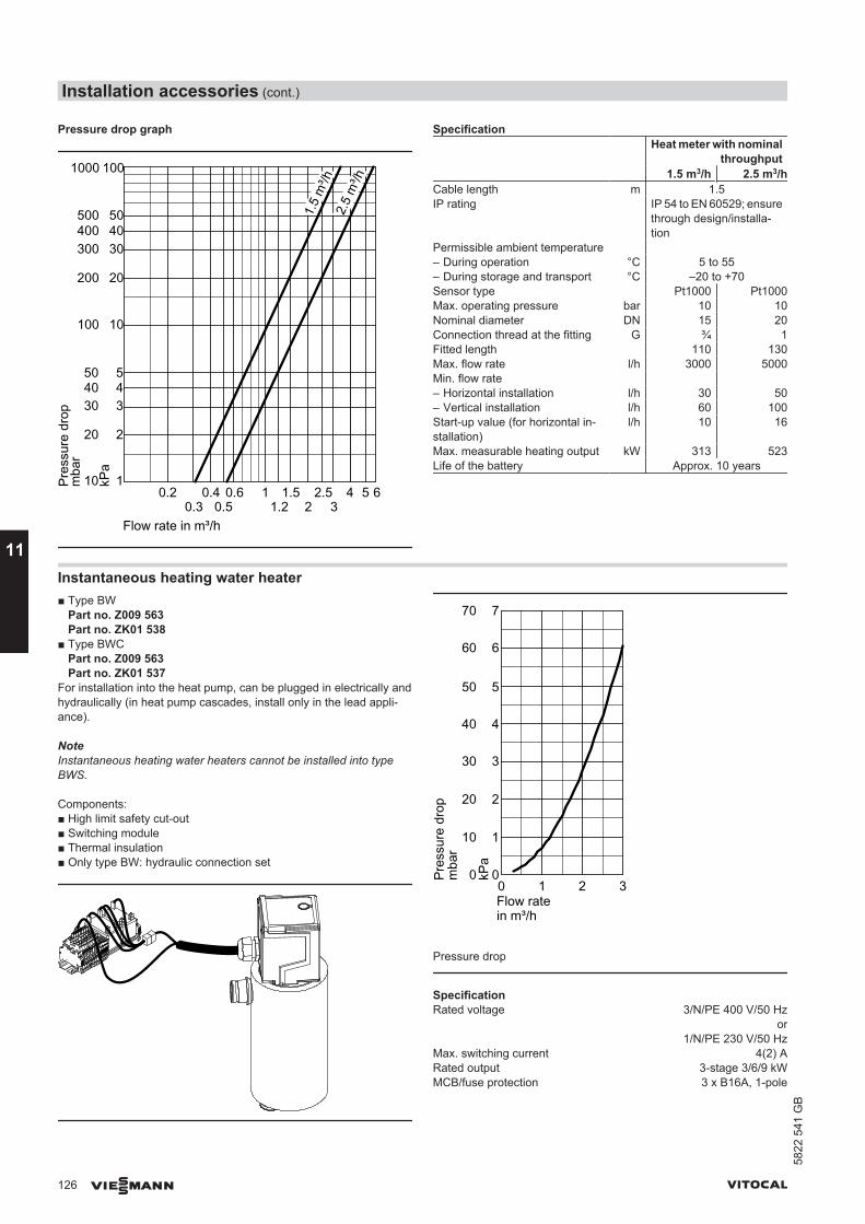
Pressure drop graph
10
20
304050
100
200
300400500
1000
0.20.3
0.4 0.60.5
1 1.51.2 2
2.53
4 5 6
Flow rate in m³/h
mba
r
1.5
m³/h
2.5
m³/h
kPa
Pres
sure
dro
p
1
2
345
10
20
304050
100
Specification Heat meter with nominal
throughput1.5 m3/h 2.5 m3/h
Cable length m 1.5IP rating IP 54 to EN 60529; ensure
through design/installa-tion
Permissible ambient temperature – During operation °C 5 to 55– During storage and transport °C –20 to +70Sensor type Pt1000 Pt1000Max. operating pressure bar 10 10Nominal diameter DN 15 20Connection thread at the fitting G ¾ 1Fitted length 110 130Max. flow rate l/h 3000 5000Min. flow rate – Horizontal installation l/h 30 50– Vertical installation l/h 60 100Start-up value (for horizontal in-stallation)
l/h 10 16
Max. measurable heating output kW 313 523Life of the battery Approx. 10 years
Instantaneous heating water heater■ Type BW
Part no. Z009 563Part no. ZK01 538
■ Type BWCPart no. Z009 563Part no. ZK01 537
For installation into the heat pump, can be plugged in electrically andhydraulically (in heat pump cascades, install only in the lead appli-ance).
NoteInstantaneous heating water heaters cannot be installed into typeBWS.
Components:■ High limit safety cut-out■ Switching module■ Thermal insulation■ Only type BW: hydraulic connection set
1
0
3
2
0 1 2 3
kPa
Flow rate in m³/h
4
5
6
7
10
0
30
20
mba
r
40
50
60
70
Pres
sure
dro
p
Pressure drop
SpecificationRated voltage 3/N/PE 400 V/50 Hz
or1/N/PE 230 V/50 Hz
Max. switching current 4(2) ARated output 3-stage 3/6/9 kWMCB/fuse protection 3 x B16A, 1-pole
Installation accessories (cont.)
126 VIESMANN VITOCAL
11
5822
541
GB

Secondary pump
Part no. 7423 916
■ High efficiency circulation pump Wilo, type Stratos PARA 25/1-7,230 V~
■ Hydraulic connection set Cu 28 mm
Wilo curves, type Stratos PARA 25/1-7 for regulation to a constantpressure ( )
0
1
2
4
3
5
6
7
0 1 2 3 4
Hea
d in
m
Pump rate in m³/h
0 1 2 3 4Pump rate in m³/h
0
40
60O
utpu
tin
W
Safety equipment block
Part no. 7143 779
Components:■ Safety valve R ½ (blow-off pressure 3 bar)■ Pressure gauge■ Automatic air vent valve with automatic shut-off facility■ Thermal insulation
23280
144
11.5 Hydraulic connection accessories
Connection set, primary/secondary circuit
Vitocal 222-G/333-G Vitocal 242-G/343-GPart no. 7418 109 Part no. 7419 752
Installation accessories (cont.)
VITOCAL VIESMANN 127
5822
541
GB
11
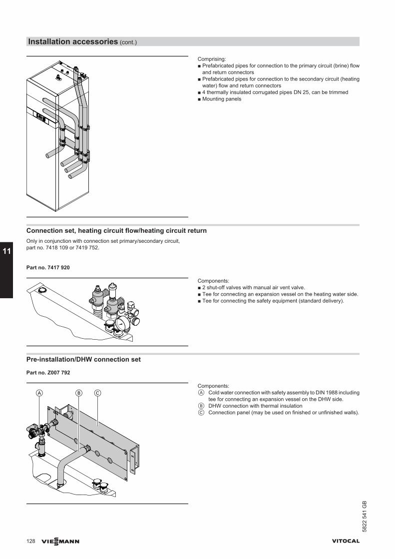
Comprising:■ Prefabricated pipes for connection to the primary circuit (brine) flow
and return connectors■ Prefabricated pipes for connection to the secondary circuit (heating
water) flow and return connectors■ 4 thermally insulated corrugated pipes DN 25, can be trimmed■ Mounting panels
Connection set, heating circuit flow/heating circuit returnOnly in conjunction with connection set primary/secondary circuit,part no. 7418 109 or 7419 752.
Part no. 7417 920
Components:■ 2 shut-off valves with manual air vent valve.■ Tee for connecting an expansion vessel on the heating water side.■ Tee for connecting the safety equipment (standard delivery).
Pre-installation/DHW connection set
Part no. Z007 792
Components:A Cold water connection with safety assembly to DIN 1988 including
tee for connecting an expansion vessel on the DHW side.B DHW connection with thermal insulationC Connection panel (may be used on finished or unfinished walls).
Installation accessories (cont.)
128 VIESMANN VITOCAL
11
5822
541
GB
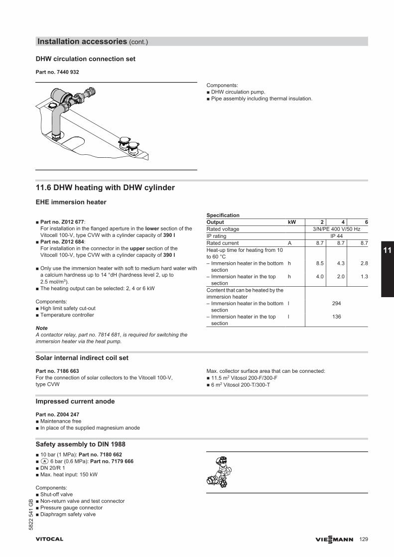
DHW circulation connection set
Part no. 7440 932
Components:■ DHW circulation pump.■ Pipe assembly including thermal insulation.
11.6 DHW heating with DHW cylinder
EHE immersion heater
■ Part no. Z012 677:For installation in the flanged aperture in the lower section of theVitocell 100-V, type CVW with a cylinder capacity of 390 l
■ Part no. Z012 684:For installation in the connector in the upper section of theVitocell 100-V, type CVW with a cylinder capacity of 390 l
■ Only use the immersion heater with soft to medium hard water witha calcium hardness up to 14 °dH (hardness level 2, up to2.5 mol/m3).
■ The heating output can be selected: 2, 4 or 6 kW
Components:■ High limit safety cut-out■ Temperature controller
NoteA contactor relay, part no. 7814 681, is required for switching theimmersion heater via the heat pump.
SpecificationOutput kW 2 4 6Rated voltage 3/N/PE 400 V/50 HzIP rating IP 44Rated current A 8.7 8.7 8.7Heat-up time for heating from 10to 60 °C
– Immersion heater in the bottomsection
h 8.5 4.3 2.8
– Immersion heater in the topsection
h 4.0 2.0 1.3
Content that can be heated by theimmersion heater
– Immersion heater in the bottomsection
l 294
– Immersion heater in the topsection
l 136
Solar internal indirect coil set
Part no. 7186 663For the connection of solar collectors to the Vitocell 100-V,type CVW
Max. collector surface area that can be connected:■ 11.5 m2 Vitosol 200-F/300-F■ 6 m2 Vitosol 200-T/300-T
Impressed current anode
Part no. Z004 247■ Maintenance free■ In place of the supplied magnesium anode
Safety assembly to DIN 1988■ 10 bar (1 MPa): Part no. 7180 662■a 6 bar (0.6 MPa): Part no. 7179 666■ DN 20/R 1■ Max. heat input: 150 kW
Components:■ Shut-off valve■ Non-return valve and test connector■ Pressure gauge connector■ Diaphragm safety valve
Installation accessories (cont.)
VITOCAL VIESMANN 129
5822
541
GB
11
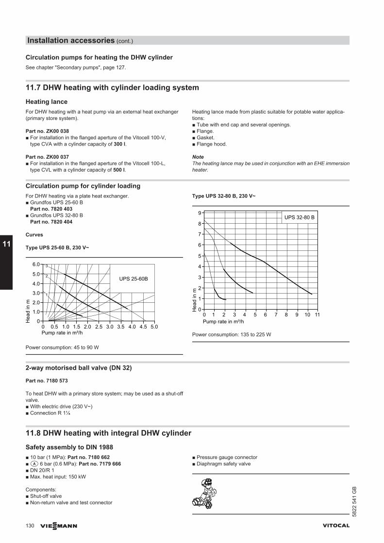
Circulation pumps for heating the DHW cylinderSee chapter "Secondary pumps", page 127.
11.7 DHW heating with cylinder loading system
Heating lanceFor DHW heating with a heat pump via an external heat exchanger(primary store system).
Part no. ZK00 038■ For installation in the flanged aperture of the Vitocell 100-V,
type CVA with a cylinder capacity of 300 l.
Part no. ZK00 037■ For installation in the flanged aperture of the Vitocell 100-L,
type CVL with a cylinder capacity of 500 l.
Heating lance made from plastic suitable for potable water applica-tions:■ Tube with end cap and several openings.■ Flange.■ Gasket.■ Flange hood.
NoteThe heating lance may be used in conjunction with an EHE immersionheater.
Circulation pump for cylinder loadingFor DHW heating via a plate heat exchanger.■ Grundfos UPS 25-60 B
Part no. 7820 403■ Grundfos UPS 32-80 B
Part no. 7820 404
Curves
Type UPS 25-60 B, 230 V~
Pump rate in m³/h0 0.5 1.0 1.5 2.0 2.5 3.0 3.5 4.0 4.5 5.0
3
2
1
0
1.0
2.0
3.0
4.0
5.0
6.0
UPS 25-60B
Hea
d in
m
Power consumption: 45 to 90 W
Type UPS 32-80 B, 230 V~
Pump rate in m³/h1 2 3 4 5 6 7 8 9 10 110
Hea
d in
m
0
1
2
3
4
5
6
7
8
9UPS 32-80 B
Power consumption: 135 to 225 W
2-way motorised ball valve (DN 32)
Part no. 7180 573
To heat DHW with a primary store system; may be used as a shut-offvalve.■ With electric drive (230 V~)■ Connection R 1¼
11.8 DHW heating with integral DHW cylinder
Safety assembly to DIN 1988■ 10 bar (1 MPa): Part no. 7180 662■a 6 bar (0.6 MPa): Part no. 7179 666■ DN 20/R 1■ Max. heat input: 150 kW
Components:■ Shut-off valve■ Non-return valve and test connector
■ Pressure gauge connector■ Diaphragm safety valve
Installation accessories (cont.)
130 VIESMANN VITOCAL
11
5822
541
GB

Impressed current anode
Part no.7182 008■ Maintenance free■ In place of the supplied magnesium anode
11.9 Installation accessories
Platform for unfinished floors
Part no. 7417 925
760600
■ With adjustable feet, for screed heights between 10 and 18 cm.■ For installation of the appliance on unfinished floors; suitable for sit-
ing tight against the wall.■ Incl. thermal insulation.
NoteIn the case of installation flush with the wall, insert edge insulationstrips for sound insulation between the platform for unfinished floorsand the wall.
Drain outlet kit
Part no. 7176 014
Drain outlet with siphon and rose.
Casing panels
■ To close the gap between the compact heat pump and the wall, 8cm wide.
■ 4 pieces in anthracite.
Vitocal 222-G/242-G Vitocal 242-G/343-GPart no. 7414 924 Part no. 7419 881
Installation accessories (cont.)
VITOCAL VIESMANN 131
5822
541
GB
11

Transport aid
Part no. 7469 270For use with the split appliance.
11.10 Cooling
NC-Box■ Without mixer
Part no. Z009 564Part no. 7462 052
■ With mixerPart no. Z009 565Part no. 7462 054
■ Cover for NC-Box, in VitosilverPart no. 7288 973
Pre-assembled unit with or without mixer, for implementing the naturalcooling function. The cooling function can optionally affect one heating/cooling circuit or a separate cooling circuit.For the connection, for example of underfloor heating systems, fanconvectors or chilled ceilings.Max. cooling capacity 5 kW (subject to the heat pump and coolingsource used).
Components:■ Plate heat exchanger■ Frost protection valve■ Frost stat■ Natural cooling contact humidistat■ Cooling circuit pump■ 3-way diverter valve (heating/cooling)■ Control of the natural cooling function■ Thermally and sound insulated, vapour diffusion-proof EPP casing■ Only for NC-Box without mixer:
– 2-way shut-off valve■ Only for NC-Box with mixer:
– Brine circuit pump– Three-way mixer with motor
510
A
194
202
241
580
B 53
72241
335370
500517
57177
311340
370
D
420
F EG
269
74
C
53
82
A Return, heating/cooling circuit or separate cooling circuitB Flow, heating/cooling circuit or separate cooling circuitC Flow, primary circuit (brine inlet, NC-Box)D Return, secondary circuit to the heat pumpE Flow, secondary circuit to the NC-BoxF Flow, primary circuit (brine outlet, NC-Box)G Cable entry
Information regarding the cooling capacityThe cooling capacity to be expected largely depends on the sizing andthe type of the heat source.The cooling capacity is at its highest at the end of the heating season.The cooling capacity diminishes with increasing loading of the groundwith heat.
Installation accessories (cont.)
132 VIESMANN VITOCAL
11
5822
541
GB
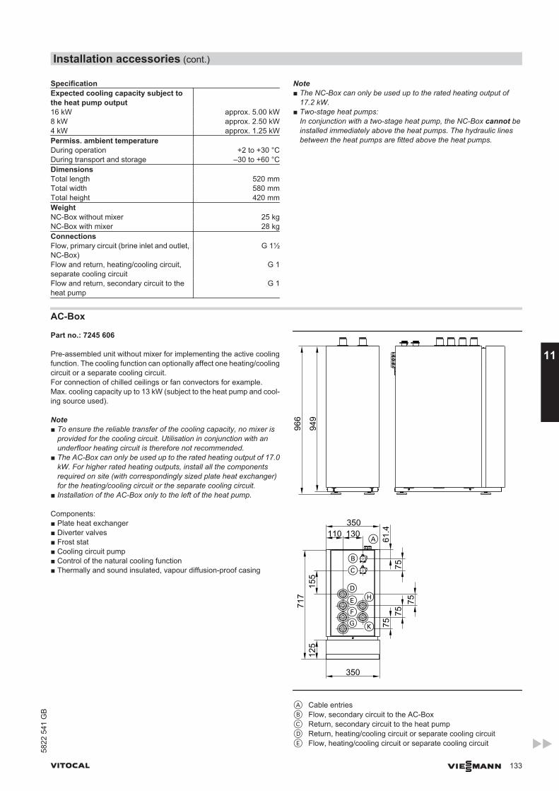
SpecificationExpected cooling capacity subject tothe heat pump output
16 kW approx. 5.00 kW8 kW approx. 2.50 kW4 kW approx. 1.25 kWPermiss. ambient temperature During operation +2 to +30 °CDuring transport and storage –30 to +60 °CDimensions Total length 520 mmTotal width 580 mmTotal height 420 mmWeight NC-Box without mixer 25 kgNC-Box with mixer 28 kgConnections Flow, primary circuit (brine inlet and outlet,NC-Box)
G 1½
Flow and return, heating/cooling circuit,separate cooling circuit
G 1
Flow and return, secondary circuit to theheat pump
G 1
Note■ The NC-Box can only be used up to the rated heating output of
17.2 kW.■ Two-stage heat pumps:
In conjunction with a two-stage heat pump, the NC-Box cannot beinstalled immediately above the heat pumps. The hydraulic linesbetween the heat pumps are fitted above the heat pumps.
AC-Box
Part no.: 7245 606
Pre-assembled unit without mixer for implementing the active coolingfunction. The cooling function can optionally affect one heating/coolingcircuit or a separate cooling circuit.For connection of chilled ceilings or fan convectors for example.Max. cooling capacity up to 13 kW (subject to the heat pump and cool-ing source used).
Note■ To ensure the reliable transfer of the cooling capacity, no mixer is
provided for the cooling circuit. Utilisation in conjunction with anunderfloor heating circuit is therefore not recommended.
■ The AC-Box can only be used up to the rated heating output of 17.0kW. For higher rated heating outputs, install all the componentsrequired on site (with correspondingly sized plate heat exchanger)for the heating/cooling circuit or the separate cooling circuit.
■ Installation of the AC-Box only to the left of the heat pump.
Components:■ Plate heat exchanger■ Diverter valves■ Frost stat■ Cooling circuit pump■ Control of the natural cooling function■ Thermally and sound insulated, vapour diffusion-proof casing
949
966
125
155
717
350110 130
350
7575
75
75
61.4
A
BC
D
EFG
H
K
A Cable entriesB Flow, secondary circuit to the AC-BoxC Return, secondary circuit to the heat pumpD Return, heating/cooling circuit or separate cooling circuitE Flow, heating/cooling circuit or separate cooling circuit
Installation accessories (cont.)
VITOCAL VIESMANN 133
5822
541
GB
11
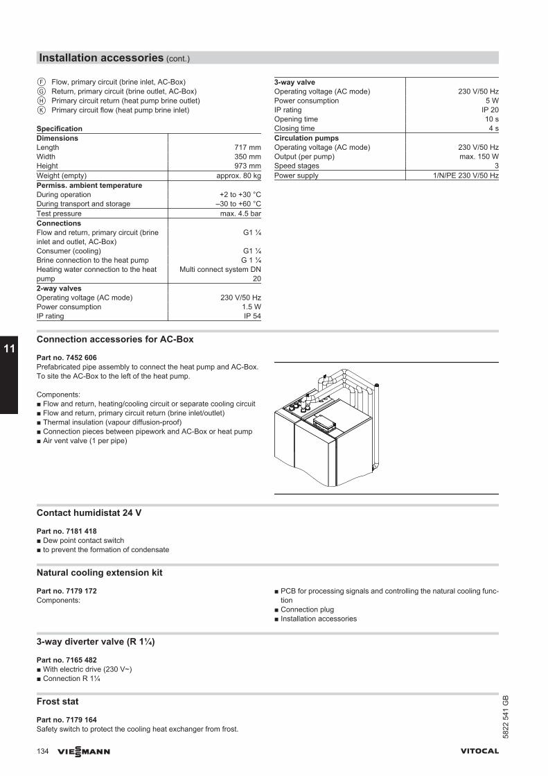
F Flow, primary circuit (brine inlet, AC-Box)G Return, primary circuit (brine outlet, AC-Box)H Primary circuit return (heat pump brine outlet)K Primary circuit flow (heat pump brine inlet)
SpecificationDimensions Length 717 mmWidth 350 mmHeight 973 mmWeight (empty) approx. 80 kgPermiss. ambient temperature During operation +2 to +30 °CDuring transport and storage –30 to +60 °CTest pressure max. 4.5 barConnections Flow and return, primary circuit (brineinlet and outlet, AC-Box)
G1 ¼
Consumer (cooling) G1 ¼Brine connection to the heat pump G 1 ¼Heating water connection to the heatpump
Multi connect system DN20
2-way valves Operating voltage (AC mode) 230 V/50 HzPower consumption 1.5 WIP rating IP 54
3-way valve Operating voltage (AC mode) 230 V/50 HzPower consumption 5 WIP rating IP 20Opening time 10 sClosing time 4 sCirculation pumps Operating voltage (AC mode) 230 V/50 HzOutput (per pump) max. 150 WSpeed stages 3Power supply 1/N/PE 230 V/50 Hz
Connection accessories for AC-Box
Part no. 7452 606Prefabricated pipe assembly to connect the heat pump and AC-Box.To site the AC-Box to the left of the heat pump.
Components:■ Flow and return, heating/cooling circuit or separate cooling circuit■ Flow and return, primary circuit return (brine inlet/outlet)■ Thermal insulation (vapour diffusion-proof)■ Connection pieces between pipework and AC-Box or heat pump■ Air vent valve (1 per pipe)
Contact humidistat 24 V
Part no. 7181 418■ Dew point contact switch■ to prevent the formation of condensate
Natural cooling extension kit
Part no. 7179 172Components:
■ PCB for processing signals and controlling the natural cooling func-tion
■ Connection plug■ Installation accessories
3-way diverter valve (R 1¼)
Part no. 7165 482■ With electric drive (230 V~)■ Connection R 1¼
Frost stat
Part no. 7179 164Safety switch to protect the cooling heat exchanger from frost.
Installation accessories (cont.)
134 VIESMANN VITOCAL
11
5822
541
GB
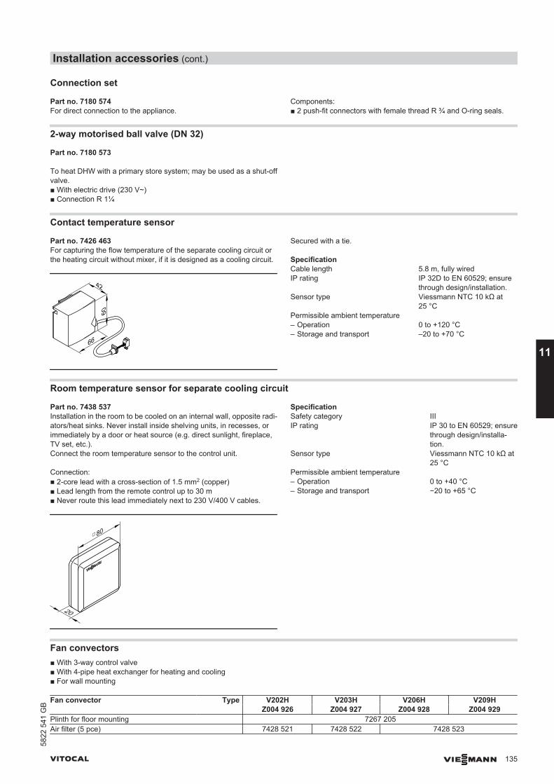
Connection set
Part no. 7180 574For direct connection to the appliance.
Components:■ 2 push-fit connectors with female thread R ¾ and O-ring seals.
2-way motorised ball valve (DN 32)
Part no. 7180 573
To heat DHW with a primary store system; may be used as a shut-offvalve.■ With electric drive (230 V~)■ Connection R 1¼
Contact temperature sensor
Part no. 7426 463For capturing the flow temperature of the separate cooling circuit orthe heating circuit without mixer, if it is designed as a cooling circuit.
42
66
60
Secured with a tie.
SpecificationCable length 5.8 m, fully wiredIP rating IP 32D to EN 60529; ensure
through design/installation.Sensor type Viessmann NTC 10 kΩ at
25 °CPermissible ambient temperature – Operation 0 to +120 °C– Storage and transport –20 to +70 °C
Room temperature sensor for separate cooling circuit
Part no. 7438 537Installation in the room to be cooled on an internal wall, opposite radi-ators/heat sinks. Never install inside shelving units, in recesses, orimmediately by a door or heat source (e.g. direct sunlight, fireplace,TV set, etc.).Connect the room temperature sensor to the control unit.
Connection:■ 2-core lead with a cross-section of 1.5 mm2 (copper)■ Lead length from the remote control up to 30 m■ Never route this lead immediately next to 230 V/400 V cables.
20
80□
SpecificationSafety category IIIIP rating IP 30 to EN 60529; ensure
through design/installa-tion.
Sensor type Viessmann NTC 10 kΩ at25 °C
Permissible ambient temperature– Operation 0 to +40 °C– Storage and transport −20 to +65 °C
Fan convectors■ With 3-way control valve■ With 4-pipe heat exchanger for heating and cooling■ For wall mounting
Fan convector Type V202H V203H V206H V209H Z004 926 Z004 927 Z004 928 Z004 929
Plinth for floor mounting 7267 205Air filter (5 pce) 7428 521 7428 522 7428 523
Installation accessories (cont.)
VITOCAL VIESMANN 135
5822
541
GB
11
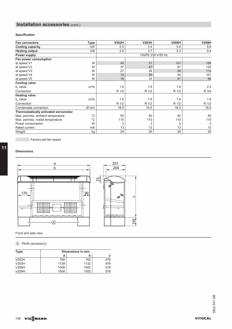
Specification
Fan convectors Type V202H V203H V206H V209HCooling capacity kW 2.0 3.4 5.6 8.8Heating output kW 2.0 3.7 5.3 9.4Power supply 1/N/PE 230 V/50 HzFan power consumption at speed V1 W 45 57 107 188at speed V2 W 37 47 81 132at speed V3 W 27 39 64 112at speed V4 W 19 36 55 101at speed V5 W 16 33 41 90Cooling valve kv value m3/h 1.6 1.6 1.6 2.5Connection R 1/2 R 1/2 R 1/2 R 3/4Heating valve kv value m3/h 1.6 1.6 1.6 1.6Connection R 1/2 R 1/2 R 1/2 R 1/2Condensate connection Ø mm 18.5 18.5 18.5 18.5Thermostatically activated servomotor Max. permiss. ambient temperature °C 50 50 50 50Max. permiss. media temperature °C 110 110 110 110Power consumption W 3 3 3 3Rated current mA 13 13 13 13Weight kg 20 30 39 50
Factory-set fan speed
Dimensions
73
c10
0
231204
90170
ab
Front and side view
A Plinth (accessory)
Type Dimensions in mma b c
V202H 768 762 478V203H 1138 1132 478V206H 1508 1502 478V209H 1508 1502 578
Installation accessories (cont.)
136 VIESMANN VITOCAL
11
5822
541
GB

100
a
bc
d
Wall mounting (front view)
A Air dischargeB TopC 4 fixing holes 7 8 mmD BottomE FloorF Air intake
Type Dimensions in mma b c d
V202H 500 430 360 150V203H 870 430 360 150V206H 1240 430 360 150V209H 1240 530 365 157
100
100g
hgh
220 220ab
ab
cdef
c de f
Position of the hydraulic connections (side view, both sides)
A R.H.B L.H.C Heating return connectionD Cooling return connectionE Heating flow connectionF Cooling flow connection
Type Dimensions in mma b c d e f g h k
V202H 98 56 237 254 390 408 147 189 518V203H 98 56 237 254 390 408 147 189 518V206H 98 56 237 254 390 408 147 189 548V209H 83 40 235 246 495 506 145 188 618
11.11 Solar
Solar circuit connection
Part no. 7180 574For direct connection to the appliance.
Components:■ 2 push-fit connectors with female thread R ¾ and O-ring seals.
Solar collectors
See the Viessmann pricelist
Max. connectable collector area■ 4.6 m2 Vitosol 200-F/300-F■ 3 m2 Vitosol 200-T/300-T
Solar-Divicon, type PS10
Part no. Z012 016
Pump station for the collector circuit■ With variable speed HE circulation pump (AC power).
Head: 6.0 m at 1000 l/h flow rate.■ With integral solar control module, type SM1.■ For aperture areas of up to 40 m2 with Vitosol 200-F, 300-F, 200-T
and 300-T.(The aperture area details refer to "Low flow systems" and are sub-ject to the system pressure drop; see technical guide for solar col-lectors.)
Installation accessories (cont.)
VITOCAL VIESMANN 137
5822
541
GB
11
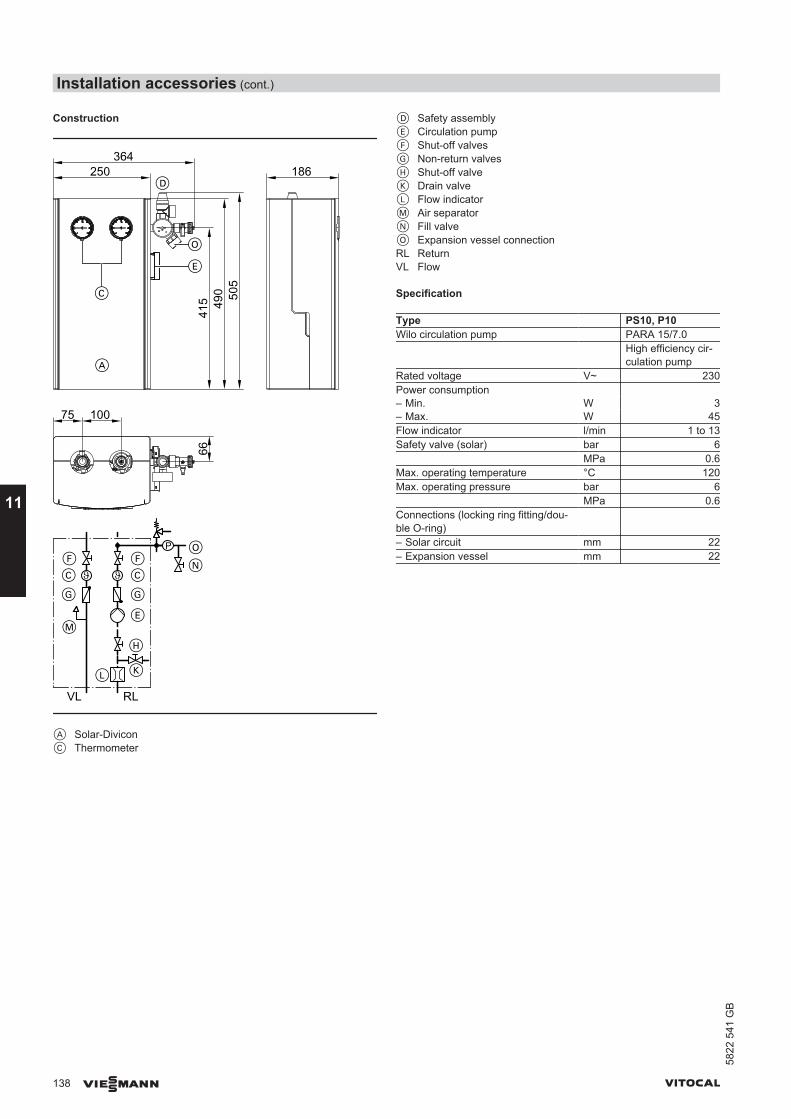
Construction
A
D
C
P
N
K
F
H
F
M
C
G
E
L
C
G
VL RL
O
O
250364
186
415 49
0 505
66
75 100
E
A Solar-DiviconC Thermometer
D Safety assemblyE Circulation pumpF Shut-off valvesG Non-return valvesH Shut-off valveK Drain valveL Flow indicatorM Air separatorN Fill valveO Expansion vessel connectionRL ReturnVL Flow
Specification
Type PS10, P10Wilo circulation pump PARA 15/7.0 High efficiency cir-
culation pumpRated voltage V~ 230Power consumption – Min. W 3– Max. W 45Flow indicator l/min 1 to 13Safety valve (solar) bar 6 MPa 0.6Max. operating temperature °C 120Max. operating pressure bar 6 MPa 0.6Connections (locking ring fitting/dou-ble O-ring)
– Solar circuit mm 22– Expansion vessel mm 22
Installation accessories (cont.)
138 VIESMANN VITOCAL
11
5822
541
GB
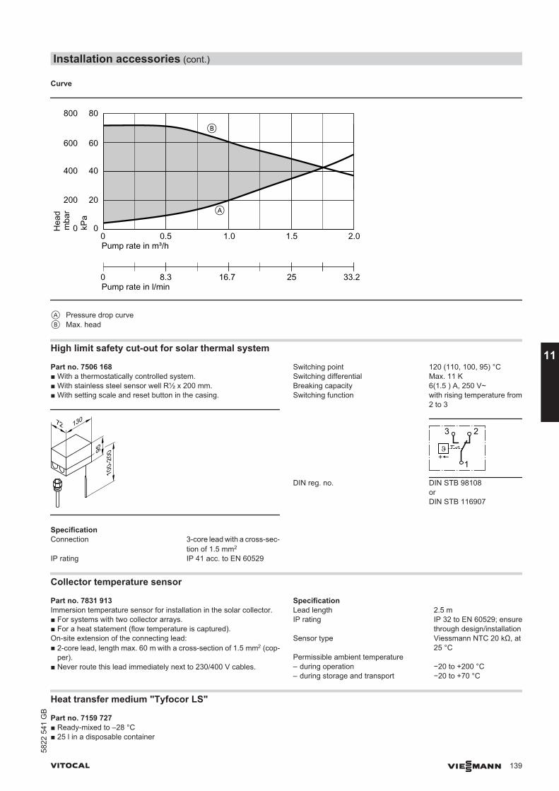
Curve
0 0.5 1.0 1.5Pump rate in m³/h
Hea
d
0
20
40
60
80
2.0
A
B
Pump rate in l/min0 8.3 16.7 25 33.2
kPa
0
200
400
600
800
mba
r
A Pressure drop curveB Max. head
High limit safety cut-out for solar thermal system
Part no. 7506 168■ With a thermostatically controlled system.■ With stainless steel sensor well R½ x 200 mm.■ With setting scale and reset button in the casing.
13072
9510
0-20
0
SpecificationConnection 3-core lead with a cross-sec-
tion of 1.5 mm2
IP rating IP 41 acc. to EN 60529
Switching point 120 (110, 100, 95) °CSwitching differential Max. 11 KBreaking capacity 6(1.5 ) A, 250 V~Switching function with rising temperature from
2 to 3
3 2
1
DIN reg. no. DIN STB 98108orDIN STB 116907
Collector temperature sensor
Part no. 7831 913Immersion temperature sensor for installation in the solar collector.■ For systems with two collector arrays.■ For a heat statement (flow temperature is captured).On-site extension of the connecting lead:■ 2-core lead, length max. 60 m with a cross-section of 1.5 mm2 (cop-
per).■ Never route this lead immediately next to 230/400 V cables.
SpecificationLead length 2.5 mIP rating IP 32 to EN 60529; ensure
through design/installationSensor type Viessmann NTC 20 kΩ, at
25 °CPermissible ambient temperature– during operation −20 to +200 °C– during storage and transport −20 to +70 °C
Heat transfer medium "Tyfocor LS"
Part no. 7159 727■ Ready-mixed to –28 °C■ 25 l in a disposable container
Installation accessories (cont.)
VITOCAL VIESMANN 139
5822
541
GB
11
12.1 Power supply and tariffsAccording to current Federal tariffs [Germany], the electrical demand for heat pumps is considered domestic usage. Where heat pumps areused to heat buildings, the local power supply company must first givepermission [check with your local power supply company].Check the connection conditions specified by your local power supplyutility for the stated equipment details. It is crucial to establish whethera mono-mode and/or mono-energetic heat pump operation is feasiblein the supply area.
It is also important to obtain information about standing charges andenergy tariffs, about the options for utilising off-peak electricity duringthe night and about any power-off periods.Address any questions relating to these issues to your customer's localpower supply utility.
Application procedureThe following details are required to assess the effect of the heat pumpoperation on the grid of your local power supply utility:■ User address■ Location where the heat pump is to be used■ Type of demand in accordance with general tariffs
(domestic, agricultural, commercial, professional and other use)
■ Intended heat pump operating mode■ Heat pump manufacturer■ Type of heat pump■ Connected load in kW (from rated voltage and rated current)■ Max. starting current in A■ Max. heat load of the building in kW
12.2 Installation requirements■ The installation room must be dry and safe from the risk of frost.■ Never install the appliance in living spaces or directly next to, below
or above quiet rooms/bedrooms.■ In conjunction with an ice store system:
Never site in rooms containing washing machines or dryers.■ Maintain the minimum clearances and minimum room volume (see
the following chapter).■ Sound insulation measures:
– Reduction of reverberative surfaces, particularly on walls and ceil-ings. Rough structural renders absorb more sound than tiles.
– If quietness is a particularly important consideration, apply sound-absorbing material to the walls and ceilings (commercially availa-ble).
– We recommend you never install this device on wooden floors inthe roof space, to prevent the transmission of structure-bornenoise.
– The doors of the installation room should correspond to at leastemission protection category E1. This is usually achieved by fittingtubular chipboard doors.
■ Hydraulic connections:– Always make hydraulic heat pump connections flexible and stress-
free (e.g. by using Viessmann heat pump accessories).– Apply anti-vibration fixings to pipework and installations.– To prevent condensation, thermally insulate lines and components
in the primary circuit with vapour diffusion-proof materials.– Provide corresponding installation areas for accessories and
expansion vessels on the brine side.
Siting Vitocal 200-G, 300-G, 350-G
Minimum clearances
NoteAdditional strain relief clamps are required for the power cables if theclearance behind the heat pump is more than 80 mm.
Design information
140 VIESMANN VITOCAL
12
5822
541
GB
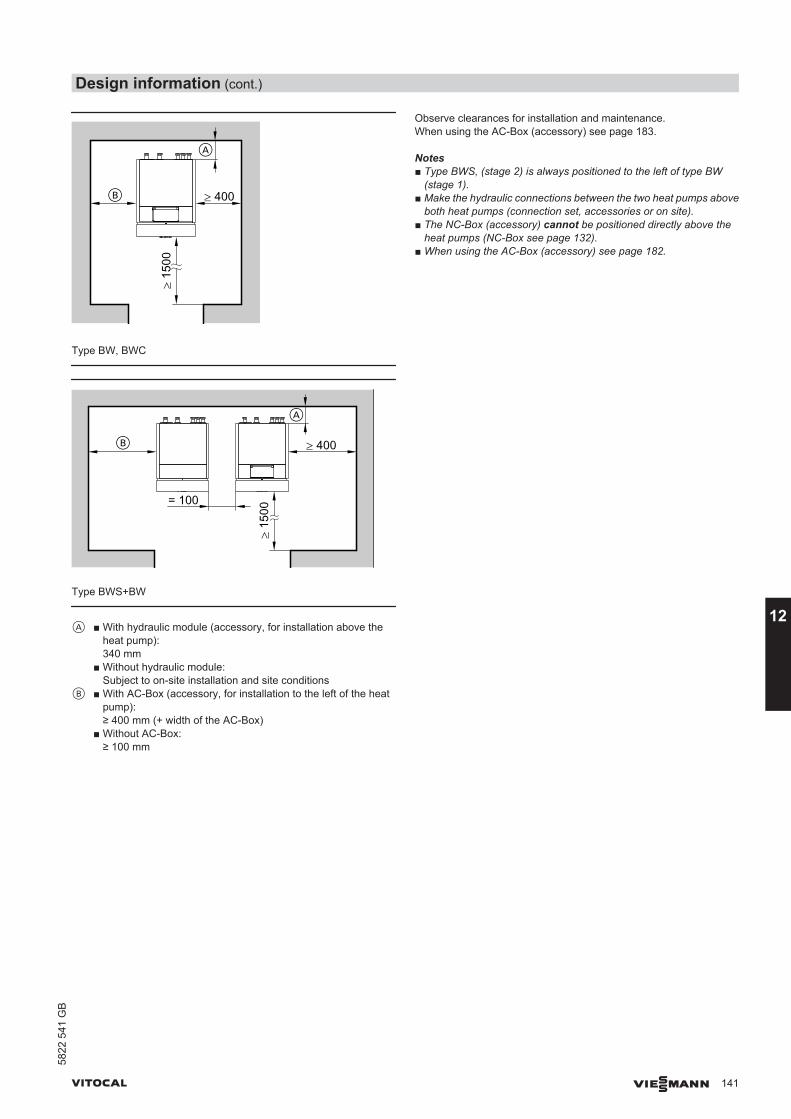
≥ 400
≥ 15
00A
B
Type BW, BWC
= 100
≥ 400
A
≥ 15
00
B
Type BWS+BW
A ■ With hydraulic module (accessory, for installation above theheat pump):340 mm
■ Without hydraulic module:Subject to on-site installation and site conditions
B ■ With AC-Box (accessory, for installation to the left of the heatpump):≥ 400 mm (+ width of the AC-Box)
■ Without AC-Box:≥ 100 mm
Observe clearances for installation and maintenance.When using the AC-Box (accessory) see page 183.
Notes■ Type BWS, (stage 2) is always positioned to the left of type BW
(stage 1).■ Make the hydraulic connections between the two heat pumps above
both heat pumps (connection set, accessories or on site).■ The NC-Box (accessory) cannot be positioned directly above the
heat pumps (NC-Box see page 132).■ When using the AC-Box (accessory) see page 182.
Design information (cont.)
VITOCAL VIESMANN 141
5822
541
GB
12
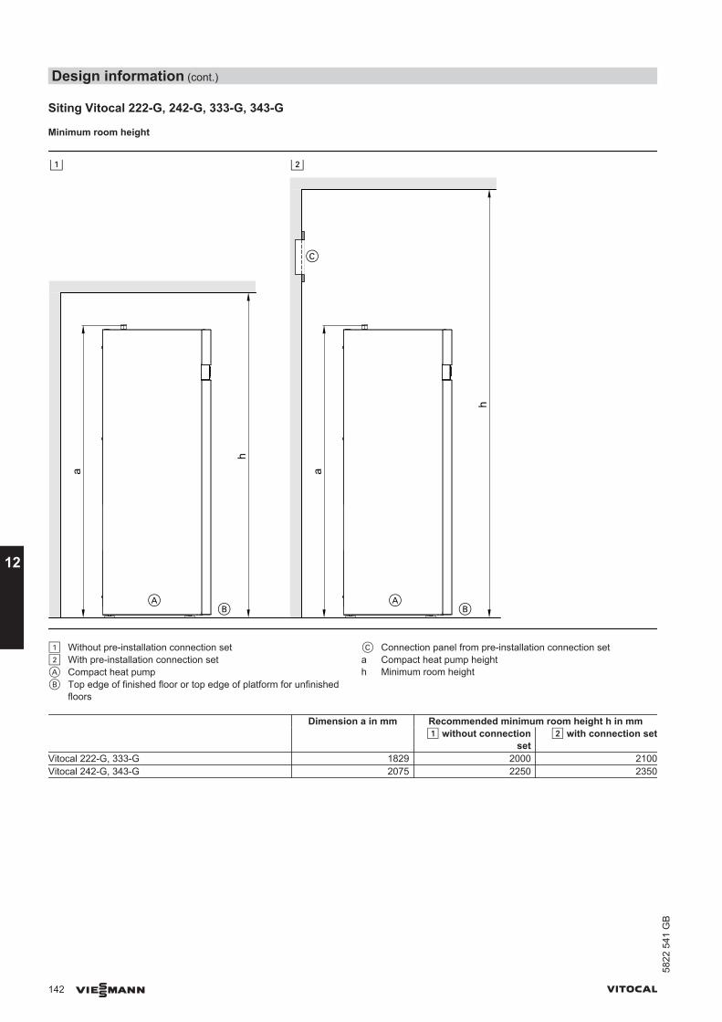
Siting Vitocal 222-G, 242-G, 333-G, 343-G
Minimum room height
! ?
AB
AB
C
a a
h
h
! Without pre-installation connection set? With pre-installation connection setA Compact heat pumpB Top edge of finished floor or top edge of platform for unfinished
floors
C Connection panel from pre-installation connection seta Compact heat pump heighth Minimum room height
Dimension a in mm Recommended minimum room height h in mm ! without connection
set? with connection set
Vitocal 222-G, 333-G 1829 2000 2100Vitocal 242-G, 343-G 2075 2250 2350
Design information (cont.)
142 VIESMANN VITOCAL
12
5822
541
GB

Minimum clearances
Vitocal 222-G, 333-G
Vitocal 242-G, 343-G
Installation in conjunction with Vitovent 300-FSee "Vitovent" technical guide.
Pressure points
b
Ø d
c a
A Partition joint with edge insulation strip as part of the floor con-struction
a 505 mmb 505 mmc 714 mmd 64 mm
NoteObserve the permissible floor load and level the appliance horizontally.If the adjustable feet are used to compensate for an uneven floor (max.10 mm), the pressure load on the individual feet must be distributedevenly.
Total weight with DHW fill in kg Vitocal 222-G Vitocal 242-G Vitocal 333-G Vitocal 343-G Type BWT 221.A Type BWT 241.A Type BWT 331.A Type BWT-NC 331.A Type BWT 341.AA06 432 491 433 435 492A08 432 491 433 438 492A10 439 498 440 446 500
Each pressure point (each with an area of 3217 mm2) is subject to a load of up to 125 kg.
Minimum spatial volumeAccording to EN 378, the minimum volume of the installation roomdepends on the refrigerant charge and composition.
Vmin = mmax /GVmin Minimum room volume in m3
mmax Maximum refrigerant charge in kgG Practical limit to EN 378, subject to the composition of the refrig-
erant
Refrigerant Practical limit in kg/m3
R410A 0.44R134a 0.25
NoteIf several heat pumps are to be installed in one room, add the minimumroom volumes together for the individual appliances.
Design information (cont.)
VITOCAL VIESMANN 143
5822
541
GB
12

Taking into account the refrigerant used and the refrigerant charge, the following minimum spatial volumes result:Vitocal Refrigerant Refrigerant charge Minimum spatial volume
in kg in m3
200-GBWC 201.A06 R410A 1.20 2.7BWC 201.A08 R410A 1.45 3.3BWC 201.A10 R410A 1.70 3.9BWC 201.A13 R410A 2.20 5.0BWC 201.A17 R410A 2.90 6.6300-G single stageBW, BWC 301.B06 R410A 1.40 3.2BW, BWC 301.B08 R410A 1.95 4.4BW, BWC 301.B10 R410A 2.40 5.5BW, BWC 301.B13 R410A 2.25 5.1BW, BWC 301.B17 R410A 2.75 6.3BW 301.A21 R410A 4.70 10.7BW 301.A29 R410A 6.20 14.1BW 301.A45 R410A 7.70 17.5300-G two-stageBW+BWS 301.B06 R410A 2.80 6.4BW+BWS 301.B08 R410A 3.90 8.9BW+BWS 301.B10 R410A 4.80 10.9BW+BWS 301.B13 R410A 4.50 10.2BW+BWS 301.B17 R410A 5.50 12.5BW+BWS 301.A21 R410A 9.40 21.4BW+BWS 301.A29 R410A 12.40 28.2BW+BWS 301.A45 R410A 14.40 32.7350-G single stageBW, BWC 351.A07 R134a 2.35 9.4BW 351.A18 R134a 5.95 23.8350-G two-stageBW+BWS 351.A07 R134a 4.70 18.8BW+BWS 351.A18 R134a 11.90 47.6222-GBWT, BWT-M 221.A06 R410A 1.80 4.1BWT, BWT-M 221.A08 R410A 1.80 4.1BWT, BWT-M 221.A10 R410A 2.20 5.0242-GBWT, BWT-M 241.A06 R410A 1.80 4.1BWT, BWT-M 241.A08 R410A 1.80 4.1BWT, BWT-M 241.A10 R410A 2.20 5.0333-GBWT, BWT-NC 331.B06 R410A 1.40 3.2BWT, BWT-NC 331.B08 R410A 1.95 4.4BWT, BWT-NC 331.B10 R410A 2.40 5.0343-GBWT 341.B06 R410A 1.40 3.2BWT 341.B08 R410A 1.95 4.4BWT 341.B10 R410A 2.40 5.0
12.3 Electrical connections for central heating and DHW heating■ Observe the technical connection requirements specified by your
local power supply utility.■ Your local power supply utility will provide you with details regarding
the required metering and switching equipment.■ We recommend the provision of a separate electricity meter for the
heat pump.
Viessmann heat pumps operate with 400 V~. In some countries,230 V models are also available.The control circuit requires a power supply of 230 V~.The control circuit fuse (6.3 A) is located in the heat pump controlunit.
Power-OFFIt is possible for the power supply utility to shut down the compressorand instantaneous heating water heater (if installed). The ability tocarry out such a shutdown may be a power supply utility requirementfor providing a lower tariff.
This must not shut off the power supply to the heat pump controlunit.
Design information (cont.)
144 VIESMANN VITOCAL
12
5822
541
GB
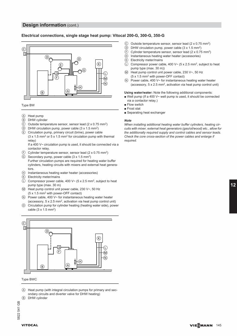
Electrical connections, single stage heat pump: Vitocal 200-G, 300-G, 350-G
C
D
B
F
E
O
G
AH
L
MN
K
Type BW
A Heat pumpB DHW cylinderC Outside temperature sensor, sensor lead (2 x 0.75 mm2)D DHW circulation pump, power cable (3 x 1.5 mm2)E Circulation pump, primary circuit (brine), power cable
(3 x 1.5 mm2 or 5 x 1.5 mm2 for circulation pump with thermalrelay)If a 400 V~ circulation pump is used, it should be connected via acontactor relay.
F Cylinder temperature sensor, sensor lead (2 x 0.75 mm2)G Secondary pump, power cable (3 x 1.5 mm2)
Further circulation pumps are required for heating water buffercylinders, heating circuits with mixers and external heat genera-tors.
H Instantaneous heating water heater (accessories)K Electricity meter/mainsL Compressor power cable, 400 V~ (5 x 2.5 mm2, subject to heat
pump type (max. 30 m)M Heat pump control unit power cable, 230 V~, 50 Hz
(5 x 1.5 mm2 with power-OFF contact)N Power cable, 400 V~ for instantaneous heating water heater
(accessory, 5 x 2.5 mm2, activation via heat pump control unit)O Circulation pump for cylinder heating (heating water side), power
cable (3 x 1.5 mm2)
C
D
B
F
AH
LMN
K
Type BWC
A Heat pump (with integral circulation pumps for primary and sec-ondary circuits and diverter valve for DHW heating)
B DHW cylinder
C Outside temperature sensor, sensor lead (2 x 0.75 mm2)D DHW circulation pump, power cable (3 x 1.5 mm2)F Cylinder temperature sensor, sensor lead (2 x 0.75 mm2)H Instantaneous heating water heater (accessories)K Electricity meter/mainsL Compressor power cable, 400 V~ (5 x 2.5 mm2, subject to heat
pump type (max. 30 m))M Heat pump control unit power cable, 230 V~, 50 Hz
(5 x 1.5 mm2 with power-OFF contact)N Power cable, 400 V~ for instantaneous heating water heater
(accessory, 5 x 2.5 mm2, activation via heat pump control unit)
Using water/water: Note the following additional components:■ Well pump (If a 400 V~ well pump is used, it should be connected
via a contactor relay.)■ Flow switch■ Frost stat■ Separating heat exchanger
NoteWhen installing additional heating water buffer cylinders, heating cir-cuits with mixer, external heat generators (gas/oil/wood) etc., allow forthe additionally required supply and control cables and sensor leads.Check the core cross-section of the power cables and enlarge ifrequired.
Design information (cont.)
VITOCAL VIESMANN 145
5822
541
GB
12
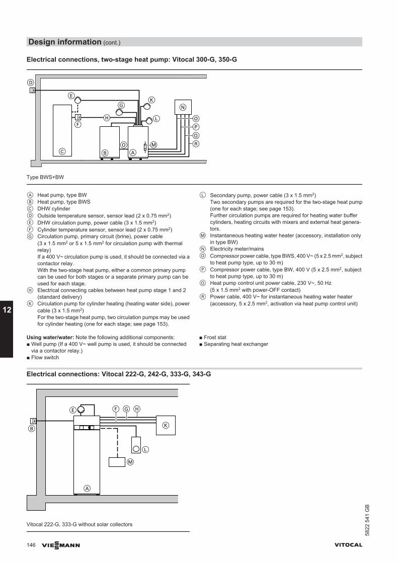
Electrical connections, two-stage heat pump: Vitocal 300-G, 350-G
D
E
C
F
GK
L
AM
P
QR
N
B
OH
O
Type BWS+BW
A Heat pump, type BWB Heat pump, type BWSC DHW cylinderD Outside temperature sensor, sensor lead (2 x 0.75 mm2)E DHW circulation pump, power cable (3 x 1.5 mm2)F Cylinder temperature sensor, sensor lead (2 x 0.75 mm2)G Circulation pump, primary circuit (brine), power cable
(3 x 1.5 mm2 or 5 x 1.5 mm2 for circulation pump with thermalrelay)If a 400 V~ circulation pump is used, it should be connected via acontactor relay.With the two-stage heat pump, either a common primary pumpcan be used for both stages or a separate primary pump can beused for each stage.
H Electrical connecting cables between heat pump stage 1 and 2(standard delivery)
K Circulation pump for cylinder heating (heating water side), powercable (3 x 1.5 mm2)For the two-stage heat pump, two circulation pumps may be usedfor cylinder heating (one for each stage; see page 153).
L Secondary pump, power cable (3 x 1.5 mm2)Two secondary pumps are required for the two-stage heat pump(one for each stage; see page 153).Further circulation pumps are required for heating water buffercylinders, heating circuits with mixers and external heat genera-tors.
M Instantaneous heating water heater (accessory, installation onlyin type BW)
N Electricity meter/mainsO Compressor power cable, type BWS, 400 V~ (5 x 2.5 mm2, subject
to heat pump type, up to 30 m)P Compressor power cable, type BW, 400 V (5 x 2.5 mm2, subject
to heat pump type, up to 30 m)Q Heat pump control unit power cable, 230 V~, 50 Hz
(5 x 1.5 mm2 with power-OFF contact)R Power cable, 400 V~ for instantaneous heating water heater
(accessory, 5 x 2.5 mm2, activation via heat pump control unit)
Using water/water: Note the following additional components:■ Well pump (If a 400 V~ well pump is used, it should be connected
via a contactor relay.)■ Flow switch
■ Frost stat■ Separating heat exchanger
Electrical connections: Vitocal 222-G, 242-G, 333-G, 343-G
Vitocal 222-G, 333-G without solar collectors
Design information (cont.)
146 VIESMANN VITOCAL
12
5822
541
GB
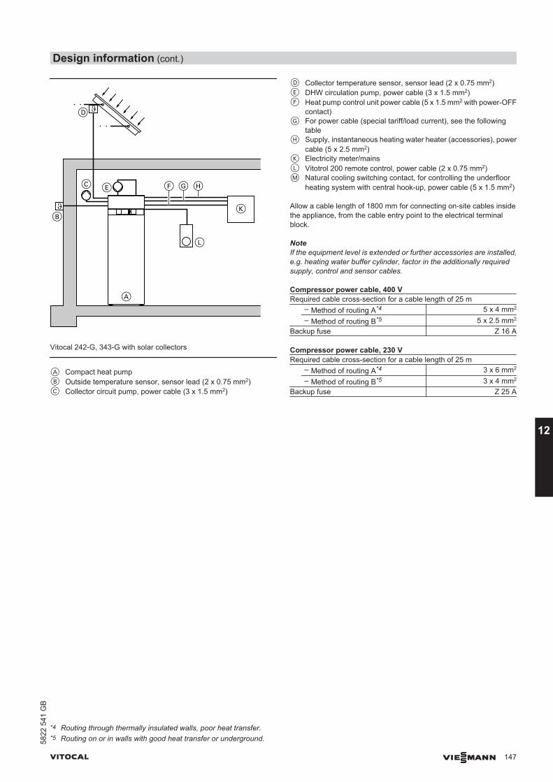
Vitocal 242-G, 343-G with solar collectors
A Compact heat pumpB Outside temperature sensor, sensor lead (2 x 0.75 mm2)C Collector circuit pump, power cable (3 x 1.5 mm2)
D Collector temperature sensor, sensor lead (2 x 0.75 mm2)E DHW circulation pump, power cable (3 x 1.5 mm2)F Heat pump control unit power cable (5 x 1.5 mm2 with power-OFF
contact)G For power cable (special tariff/load current), see the following
tableH Supply, instantaneous heating water heater (accessories), power
cable (5 x 2.5 mm2)K Electricity meter/mainsL Vitotrol 200 remote control, power cable (2 x 0.75 mm2)M Natural cooling switching contact, for controlling the underfloor
heating system with central hook-up, power cable (5 x 1.5 mm2)
Allow a cable length of 1800 mm for connecting on-site cables insidethe appliance, from the cable entry point to the electrical terminalblock.
NoteIf the equipment level is extended or further accessories are installed,e.g. heating water buffer cylinder, factor in the additionally requiredsupply, control and sensor cables.
Compressor power cable, 400 VRequired cable cross-section for a cable length of 25 m – Method of routing A*4 5 x 4 mm2
– Method of routing B*5 5 x 2.5 mm2
Backup fuse Z 16 A
Compressor power cable, 230 VRequired cable cross-section for a cable length of 25 m – Method of routing A*4 3 x 6 mm2
– Method of routing B*5 3 x 4 mm2
Backup fuse Z 25 A
*4 Routing through thermally insulated walls, poor heat transfer.*5 Routing on or in walls with good heat transfer or underground.
Design information (cont.)
VITOCAL VIESMANN 147
5822
541
GB
12
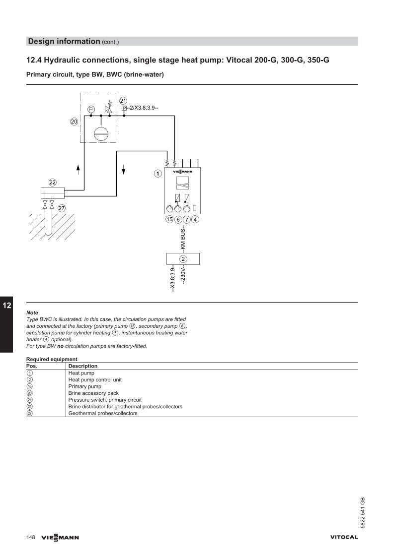
12.4 Hydraulic connections, single stage heat pump: Vitocal 200-G, 300-G, 350-G
Primary circuit, type BW, BWC (brine-water)
22
27
2
--K
M B
US
--
--X
3.8;
3.9-
-
--23
0V--
P1
P1
20
21--2/X3.8;3.9--
11
615 7 4
P
NoteType BWC is illustrated. In this case, the circulation pumps are fittedand connected at the factory (primary pump qT, secondary pump 6,circulation pump for cylinder heating 7, instantaneous heating waterheater 4 optional).For type BW no circulation pumps are factory-fitted.
Required equipmentPos. Description1 Heat pump2 Heat pump control unitqT Primary pumpwP Brine accessory packwQ Pressure switch, primary circuitwW Brine distributor for geothermal probes/collectorswU Geothermal probes/collectors
Design information (cont.)
148 VIESMANN VITOCAL
12
5822
541
GB
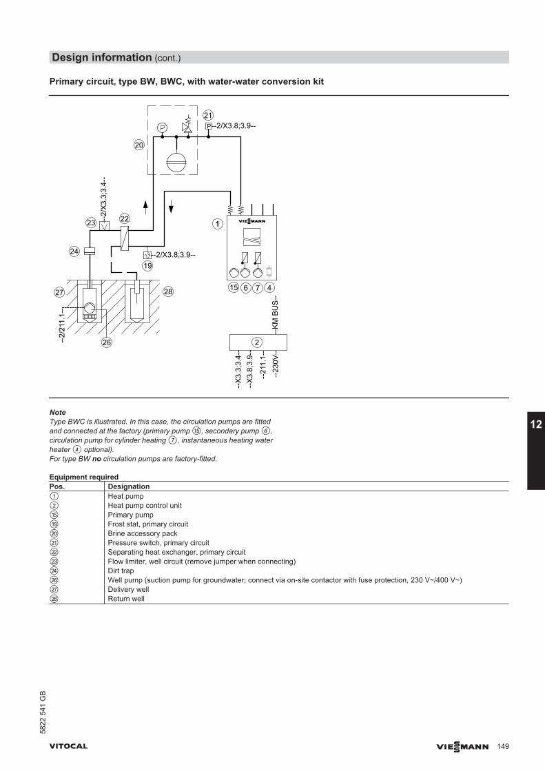
Primary circuit, type BW, BWC, with water-water conversion kit
19
24
26
28
22
20
2
--K
M B
US
--
--X
3.8;
3.9-
-
--21
1.1-
-
--23
0V--
--2/X3.8;3.9--
--2/
211.
1--
27
---------
P1
P1
--2/
X3.
3;3.
4--
23
--X
3.3;
3.4-
-
21--2/X3.8;3.9--
11
615 7 4
P
NoteType BWC is illustrated. In this case, the circulation pumps are fittedand connected at the factory (primary pump qT, secondary pump 6,circulation pump for cylinder heating 7, instantaneous heating waterheater 4 optional).For type BW no circulation pumps are factory-fitted.
Equipment requiredPos. Designation1 Heat pump2 Heat pump control unitqT Primary pumpqO Frost stat, primary circuitwP Brine accessory packwQ Pressure switch, primary circuitwW Separating heat exchanger, primary circuitwE Flow limiter, well circuit (remove jumper when connecting)wR Dirt trapwZ Well pump (suction pump for groundwater; connect via on-site contactor with fuse protection, 230 V~/400 V~)wU Delivery wellwI Return well
Design information (cont.)
VITOCAL VIESMANN 149
5822
541
GB
12

12.5 Hydraulic connections, two-stage heat pump, heat pump cascade: Vitocal 300-G,350-G
Primary circuit, two-stage, type BW+BWS (brine-water)
2 primary pumps
22
27
9
20
21--2/X3.8;3.9--
1
2
--K
M B
US
--
--X
3.8;
3.9-
-
--23
0V--
P1 P1
P1 P1
--F2--16
--2/224.2-- --2/211.1----F3--
17
--F2
----
211.
1--
--F3
----
224.
2--
25 15
P
NoteWhen using an hydraulic module (secondary circuit), integrate the pri-mary pumps qT and wT in the respective heat pump.
Equipment requiredPos. Description1 Heat pump stage 12 Heat pump control unit9 Heat pump stage 2qT Primary pump, heat pump stage 1qZ Flow temperature sensor, primary circuitqU Return temperature sensor, primary circuitwP Brine accessory packwQ Pressure switch, primary circuitwW Brine distributor, geothermal probes/collectorswT Primary pump, heat pump stage 2wU Geothermal probes/collectors
One common primary pump
NoteIf the first and second stage heat pumps (type BW+BWS) are installedwith different rated heating outputs, two primary pumps must be useddue to the different flow rates.
Design information (cont.)
150 VIESMANN VITOCAL
12
5822
541
GB
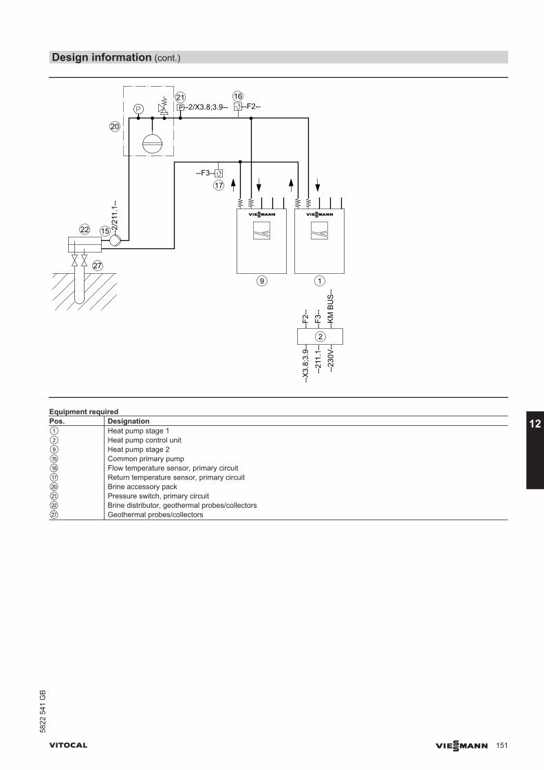
22
27
9
20
21--2/X3.8;3.9--
1
2--
KM
BU
S--
--X
3.8;
3.9-
-
--23
0V--
P1 P1
P1 P1
--F2--16
--2/
211.
1--
--F3--
17
--F2
--
--21
1.1-
---
F3--
15
P
Equipment requiredPos. Designation1 Heat pump stage 12 Heat pump control unit9 Heat pump stage 2qT Common primary pumpqZ Flow temperature sensor, primary circuitqU Return temperature sensor, primary circuitwP Brine accessory packwQ Pressure switch, primary circuitwW Brine distributor, geothermal probes/collectorswU Geothermal probes/collectors
Design information (cont.)
VITOCAL VIESMANN 151
5822
541
GB
12
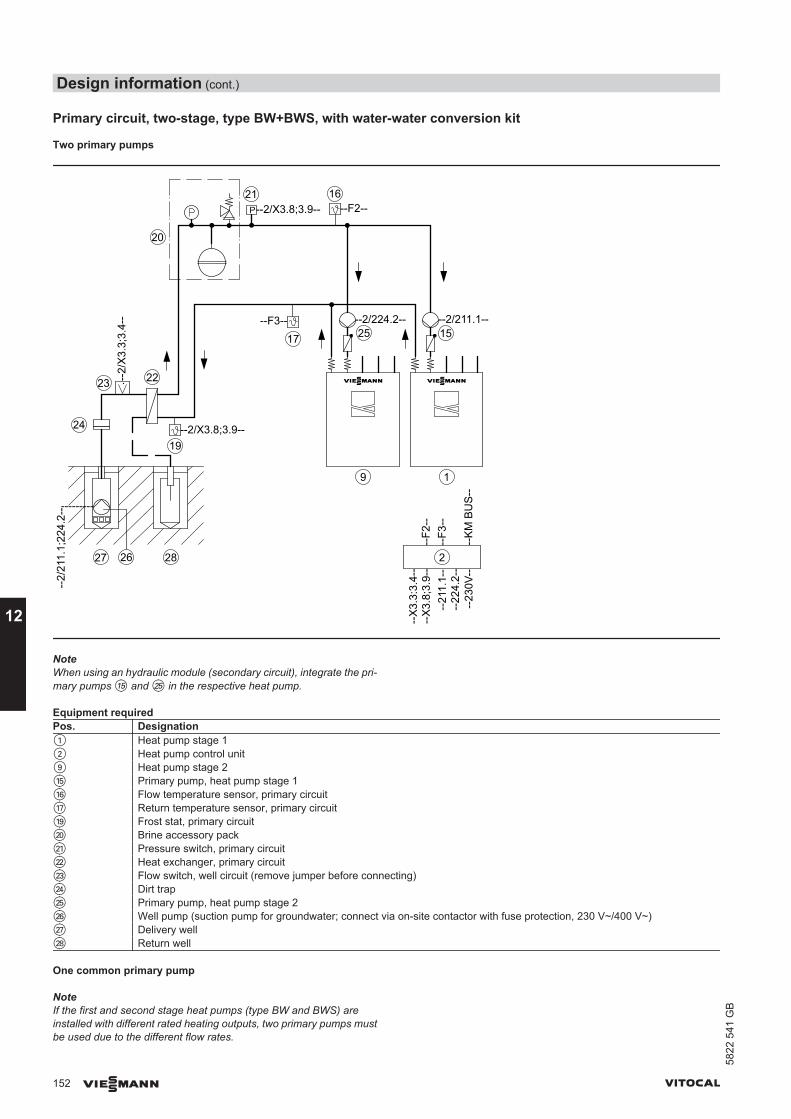
Primary circuit, two-stage, type BW+BWS, with water-water conversion kit
Two primary pumps
19
24
26 28
22
20
--2/X3.8;3.9--
--2/
211.
1;22
4.2-
-
27
---------
P1
P1
--2/
X3.
3;3.
4--
23
21--2/X3.8;3.9--
9 1
2
--K
M B
US
--
--X
3.8;
3.9-
-
--23
0V--
P1 P1
P1 P1
--F2--16
--2/224.2-- --2/211.1----F3--
17
--F2
----
211.
1--
--F3
----
224.
2--
25 15
--X
3.3:
3.4-
-
P
NoteWhen using an hydraulic module (secondary circuit), integrate the pri-mary pumps qT and wT in the respective heat pump.
Equipment requiredPos. Designation1 Heat pump stage 12 Heat pump control unit9 Heat pump stage 2qT Primary pump, heat pump stage 1qZ Flow temperature sensor, primary circuitqU Return temperature sensor, primary circuitqO Frost stat, primary circuitwP Brine accessory packwQ Pressure switch, primary circuitwW Heat exchanger, primary circuitwE Flow switch, well circuit (remove jumper before connecting)wR Dirt trapwT Primary pump, heat pump stage 2wZ Well pump (suction pump for groundwater; connect via on-site contactor with fuse protection, 230 V~/400 V~)wU Delivery wellwI Return well
One common primary pump
NoteIf the first and second stage heat pumps (type BW and BWS) areinstalled with different rated heating outputs, two primary pumps mustbe used due to the different flow rates.
Design information (cont.)
152 VIESMANN VITOCAL
12
5822
541
GB
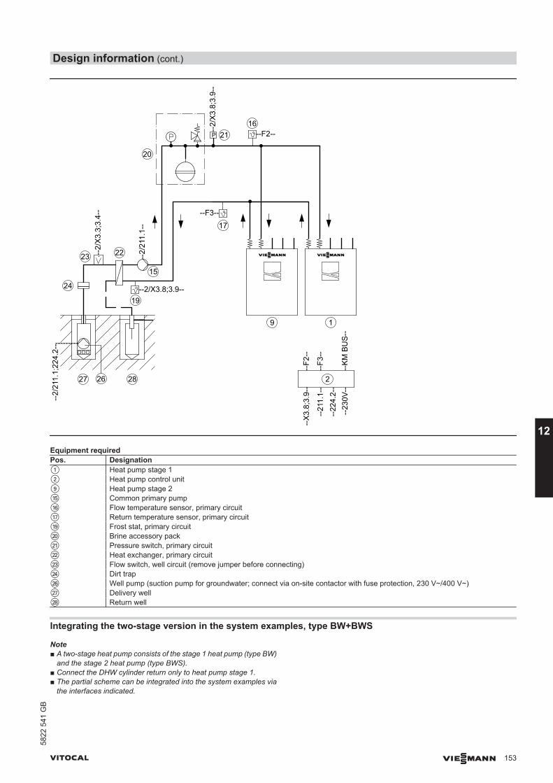
19
24
26 28
22
20
--2/X3.8;3.9--
--2/
211.
1;22
4.2-
-
27
---------
P1
P1
--2/
X3.
3;3.
4--
23
21
--2/
X3.
8;3.
9--
9 1
2
--K
M B
US
--
--X
3.8;
3.9-
-
--23
0V--
P1 P1
P1 P1
--F2--16
--F3--
17
--F2
--
--21
1.1-
---
F3--
--2/
211.
1--
15
--22
4.2-
-
P
Equipment requiredPos. Designation1 Heat pump stage 12 Heat pump control unit9 Heat pump stage 2qT Common primary pumpqZ Flow temperature sensor, primary circuitqU Return temperature sensor, primary circuitqO Frost stat, primary circuitwP Brine accessory packwQ Pressure switch, primary circuitwW Heat exchanger, primary circuitwE Flow switch, well circuit (remove jumper before connecting)wR Dirt trapwZ Well pump (suction pump for groundwater; connect via on-site contactor with fuse protection, 230 V~/400 V~)wU Delivery wellwI Return well
Integrating the two-stage version in the system examples, type BW+BWS
Note■ A two-stage heat pump consists of the stage 1 heat pump (type BW)
and the stage 2 heat pump (type BWS).■ Connect the DHW cylinder return only to heat pump stage 1.■ The partial scheme can be integrated into the system examples via
the interfaces indicated.
Design information (cont.)
VITOCAL VIESMANN 153
5822
541
GB
12
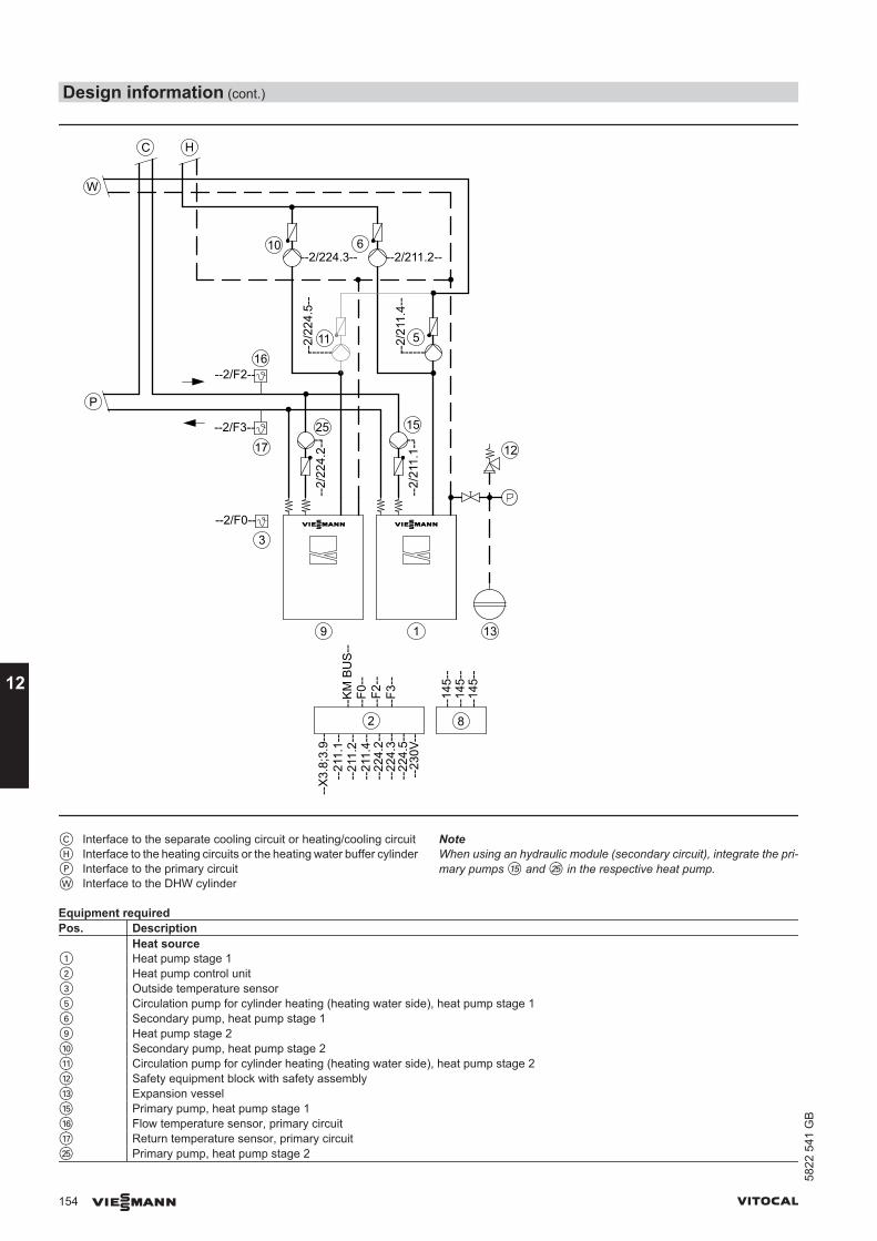
9 1
2
--X
3.8;
3.9-
-
--2/F2--16
--
--F2
--
--21
1.1-
-
--F3
--
--21
1.2-
-
25 15--2/F3--
17
3
--14
5--
8
--14
5--
--14
5--
--2/F0--
P1
P1
--2/
224.
2-- --
--2/
211.
1--
12
13
W
HC
P
10 6
11 5
--2/224.3-- --2/211.2--
--------2/
224.
5--
--------2/
211.
4--
--F0
----
211.
4--
--22
4.3-
---
224.
2--
--K
M B
US
--
--23
0V--
--22
4.5-
-
C Interface to the separate cooling circuit or heating/cooling circuitH Interface to the heating circuits or the heating water buffer cylinderP Interface to the primary circuitW Interface to the DHW cylinder
NoteWhen using an hydraulic module (secondary circuit), integrate the pri-mary pumps qT and wT in the respective heat pump.
Equipment requiredPos. Description Heat source1 Heat pump stage 12 Heat pump control unit3 Outside temperature sensor5 Circulation pump for cylinder heating (heating water side), heat pump stage 16 Secondary pump, heat pump stage 19 Heat pump stage 2qP Secondary pump, heat pump stage 2qQ Circulation pump for cylinder heating (heating water side), heat pump stage 2qW Safety equipment block with safety assemblyqE Expansion vesselqT Primary pump, heat pump stage 1qZ Flow temperature sensor, primary circuitqU Return temperature sensor, primary circuitwT Primary pump, heat pump stage 2
Design information (cont.)
154 VIESMANN VITOCAL
12
5822
541
GB
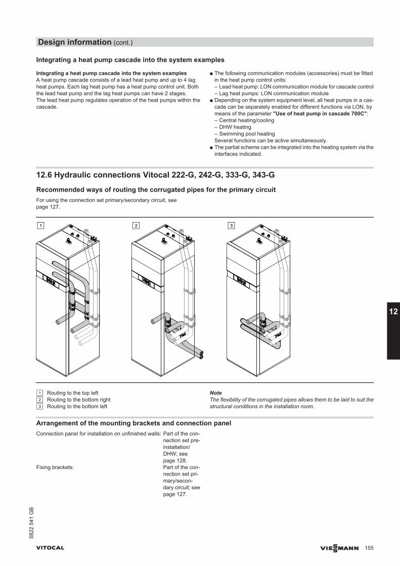
Integrating a heat pump cascade into the system examples
Integrating a heat pump cascade into the system examplesA heat pump cascade consists of a lead heat pump and up to 4 lagheat pumps. Each lag heat pump has a heat pump control unit. Boththe lead heat pump and the lag heat pumps can have 2 stages.The lead heat pump regulates operation of the heat pumps within thecascade.
■ The following communication modules (accessories) must be fittedin the heat pump control units:– Lead heat pump: LON communication module for cascade control– Lag heat pumps: LON communication module
■ Depending on the system equipment level, all heat pumps in a cas-cade can be separately enabled for different functions via LON, bymeans of the parameter "Use of heat pump in cascade 700C":– Central heating/cooling– DHW heating– Swimming pool heatingSeveral functions can be active simultaneously.
■ The partial scheme can be integrated into the heating system via theinterfaces indicated.
12.6 Hydraulic connections Vitocal 222-G, 242-G, 333-G, 343-G
Recommended ways of routing the corrugated pipes for the primary circuitFor using the connection set primary/secondary circuit, seepage 127.
! Routing to the top left? Routing to the bottom right§ Routing to the bottom left
NoteThe flexibility of the corrugated pipes allows them to be laid to suit thestructural conditions in the installation room.
Arrangement of the mounting brackets and connection panelConnection panel for installation on unfinished walls: Part of the con-
nection set pre-installation/DHW; seepage 128.
Fixing brackets: Part of the con-nection set pri-mary/secon-dary circuit; seepage 127.
Design information (cont.)
VITOCAL VIESMANN 155
5822
541
GB
12
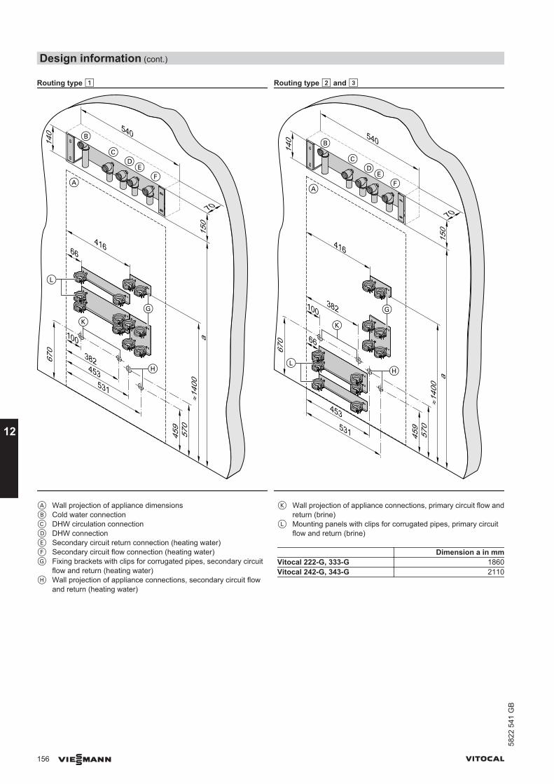
Routing type ! Routing type ? and §
≈140
0
670
100
382453
531
459
570
a15
070
540
140
66416
≈140
0
670
100382
453531
459
570
a15
0
70
540
140
66
416
A Wall projection of appliance dimensionsB Cold water connectionC DHW circulation connectionD DHW connectionE Secondary circuit return connection (heating water)F Secondary circuit flow connection (heating water)G Fixing brackets with clips for corrugated pipes, secondary circuit
flow and return (heating water)H Wall projection of appliance connections, secondary circuit flow
and return (heating water)
K Wall projection of appliance connections, primary circuit flow andreturn (brine)
L Mounting panels with clips for corrugated pipes, primary circuitflow and return (brine)
Dimension a in mmVitocal 222-G, 333-G 1860Vitocal 242-G, 343-G 2110
Design information (cont.)
156 VIESMANN VITOCAL
12
5822
541
GB
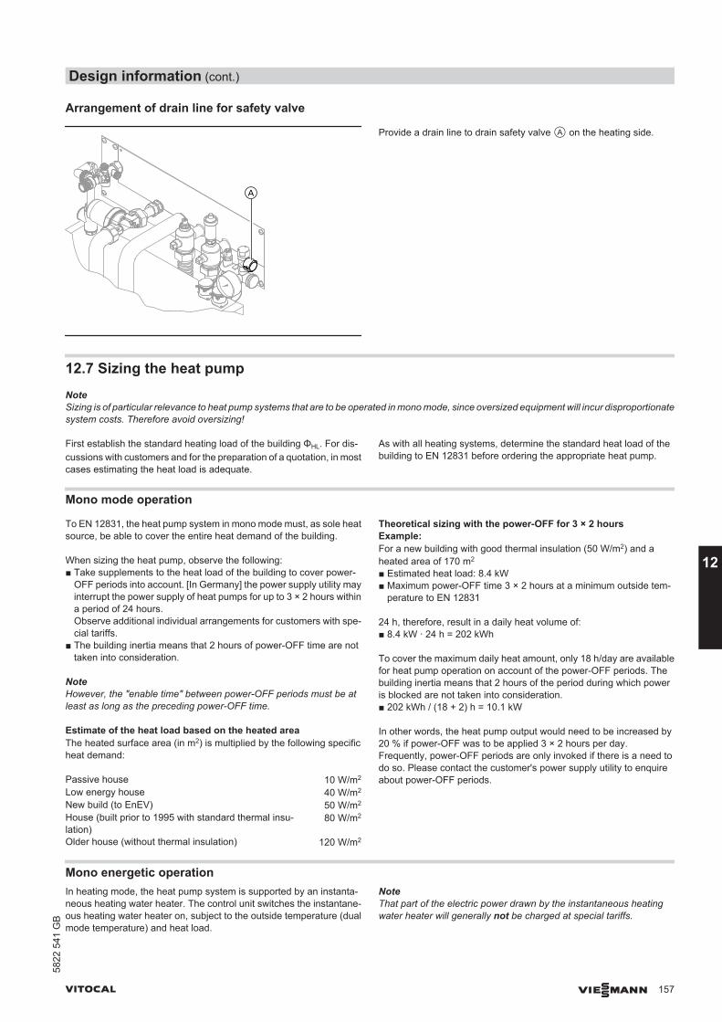
Arrangement of drain line for safety valve
Provide a drain line to drain safety valve A on the heating side.
12.7 Sizing the heat pumpNoteSizing is of particular relevance to heat pump systems that are to be operated in mono mode, since oversized equipment will incur disproportionatesystem costs. Therefore avoid oversizing!
First establish the standard heating load of the building ΦHL. For dis-cussions with customers and for the preparation of a quotation, in mostcases estimating the heat load is adequate.
As with all heating systems, determine the standard heat load of thebuilding to EN 12831 before ordering the appropriate heat pump.
Mono mode operation
To EN 12831, the heat pump system in mono mode must, as sole heatsource, be able to cover the entire heat demand of the building.
When sizing the heat pump, observe the following:■ Take supplements to the heat load of the building to cover power-
OFF periods into account. [In Germany] the power supply utility mayinterrupt the power supply of heat pumps for up to 3 × 2 hours withina period of 24 hours.Observe additional individual arrangements for customers with spe-cial tariffs.
■ The building inertia means that 2 hours of power-OFF time are nottaken into consideration.
NoteHowever, the "enable time" between power-OFF periods must be atleast as long as the preceding power-OFF time.
Estimate of the heat load based on the heated areaThe heated surface area (in m2) is multiplied by the following specificheat demand:
Passive house 10 W/m2
Low energy house 40 W/m2
New build (to EnEV) 50 W/m2
House (built prior to 1995 with standard thermal insu-lation)
80 W/m2
Older house (without thermal insulation) 120 W/m2
Theoretical sizing with the power-OFF for 3 × 2 hoursExample:For a new building with good thermal insulation (50 W/m2) and aheated area of 170 m2
■ Estimated heat load: 8.4 kW■ Maximum power-OFF time 3 × 2 hours at a minimum outside tem-
perature to EN 12831
24 h, therefore, result in a daily heat volume of:■ 8.4 kW ∙ 24 h = 202 kWh
To cover the maximum daily heat amount, only 18 h/day are availablefor heat pump operation on account of the power-OFF periods. Thebuilding inertia means that 2 hours of the period during which poweris blocked are not taken into consideration.■ 202 kWh / (18 + 2) h = 10.1 kW
In other words, the heat pump output would need to be increased by20 % if power-OFF was to be applied 3 × 2 hours per day.Frequently, power-OFF periods are only invoked if there is a need todo so. Please contact the customer's power supply utility to enquireabout power-OFF periods.
Mono energetic operationIn heating mode, the heat pump system is supported by an instanta-neous heating water heater. The control unit switches the instantane-ous heating water heater on, subject to the outside temperature (dualmode temperature) and heat load.
NoteThat part of the electric power drawn by the instantaneous heatingwater heater will generally not be charged at special tariffs.
Design information (cont.)
VITOCAL VIESMANN 157
5822
541
GB
12
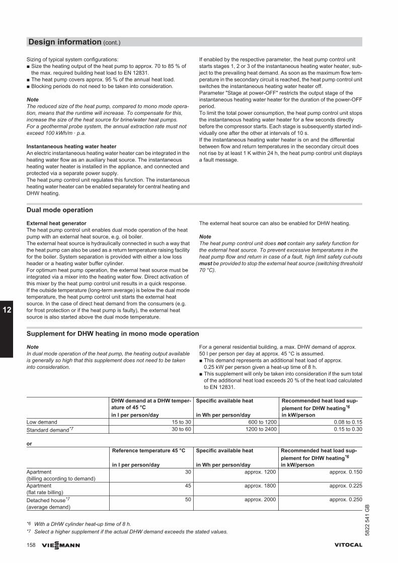
Sizing of typical system configurations:■ Size the heating output of the heat pump to approx. 70 to 85 % of
the max. required building heat load to EN 12831.■ The heat pump covers approx. 95 % of the annual heat load.■ Blocking periods do not need to be taken into consideration.
NoteThe reduced size of the heat pump, compared to mono mode opera-tion, means that the runtime will increase. To compensate for this,increase the size of the heat source for brine/water heat pumps.For a geothermal probe system, the annual extraction rate must notexceed 100 kWh/m ∙ p.a.
Instantaneous heating water heaterAn electric instantaneous heating water heater can be integrated in theheating water flow as an auxiliary heat source. The instantaneousheating water heater is installed in the appliance, and connected andprotected via a separate power supply.The heat pump control unit regulates this function. The instantaneousheating water heater can be enabled separately for central heating andDHW heating.
If enabled by the respective parameter, the heat pump control unitstarts stages 1, 2 or 3 of the instantaneous heating water heater, sub-ject to the prevailing heat demand. As soon as the maximum flow tem-perature in the secondary circuit is reached, the heat pump control unitswitches the instantaneous heating water heater off.Parameter "Stage at power-OFF" restricts the output stage of theinstantaneous heating water heater for the duration of the power-OFFperiod.To limit the total power consumption, the heat pump control unit stopsthe instantaneous heating water heater for a few seconds directlybefore the compressor starts. Each stage is subsequently started indi-vidually one after the other at intervals of 10 s.If the instantaneous heating water heater is on and the differentialbetween flow and return temperatures in the secondary circuit doesnot rise by at least 1 K within 24 h, the heat pump control unit displaysa fault message.
Dual mode operation
External heat generatorThe heat pump control unit enables dual mode operation of the heatpump with an external heat source, e.g. oil boiler.The external heat source is hydraulically connected in such a way thatthe heat pump can also be used as a return temperature raising facilityfor the boiler. System separation is provided with either a low lossheader or a heating water buffer cylinder.For optimum heat pump operation, the external heat source must beintegrated via a mixer into the heating water flow. Direct activation ofthis mixer by the heat pump control unit results in a quick response.If the outside temperature (long-term average) is below the dual modetemperature, the heat pump control unit starts the external heatsource. In the case of direct heat demand from the consumers (e.g.for frost protection or if the heat pump is faulty), the external heatsource is also started above the dual mode temperature.
The external heat source can also be enabled for DHW heating.
NoteThe heat pump control unit does not contain any safety function forthe external heat source. To prevent excessive temperatures in theheat pump flow and return in case of a fault, high limit safety cut-outsmust be provided to stop the external heat source (switching threshold70 °C).
Supplement for DHW heating in mono mode operation
NoteIn dual mode operation of the heat pump, the heating output availableis generally so high that this supplement does not need to be takeninto consideration.
For a general residential building, a max. DHW demand of approx.50 l per person per day at approx. 45 °C is assumed.■ This demand represents an additional heat load of approx.
0.25 kW per person given a heat-up time of 8 h.■ This supplement will only be taken into consideration if the sum total
of the additional heat load exceeds 20 % of the heat load calculatedto EN 12831.
DHW demand at a DHW temper-ature of 45 °C
Specific available heat Recommended heat load sup-plement for DHW heating*6
in l per person/day in Wh per person/day in kW/personLow demand 15 to 30 600 to 1200 0.08 to 0.15Standard demand*7 30 to 60 1200 to 2400 0.15 to 0.30
or Reference temperature 45 °C Specific available heat Recommended heat load sup-
plement for DHW heating*6
in l per person/day in Wh per person/day in kW/personApartment(billing according to demand)
30 approx. 1200 approx. 0.150
Apartment(flat rate billing)
45 approx. 1800 approx. 0.225
Detached house*7
(average demand)50 approx. 2000 approx. 0.250
*6 With a DHW cylinder heat-up time of 8 h.*7 Select a higher supplement if the actual DHW demand exceeds the stated values.
Design information (cont.)
158 VIESMANN VITOCAL
12
5822
541
GB
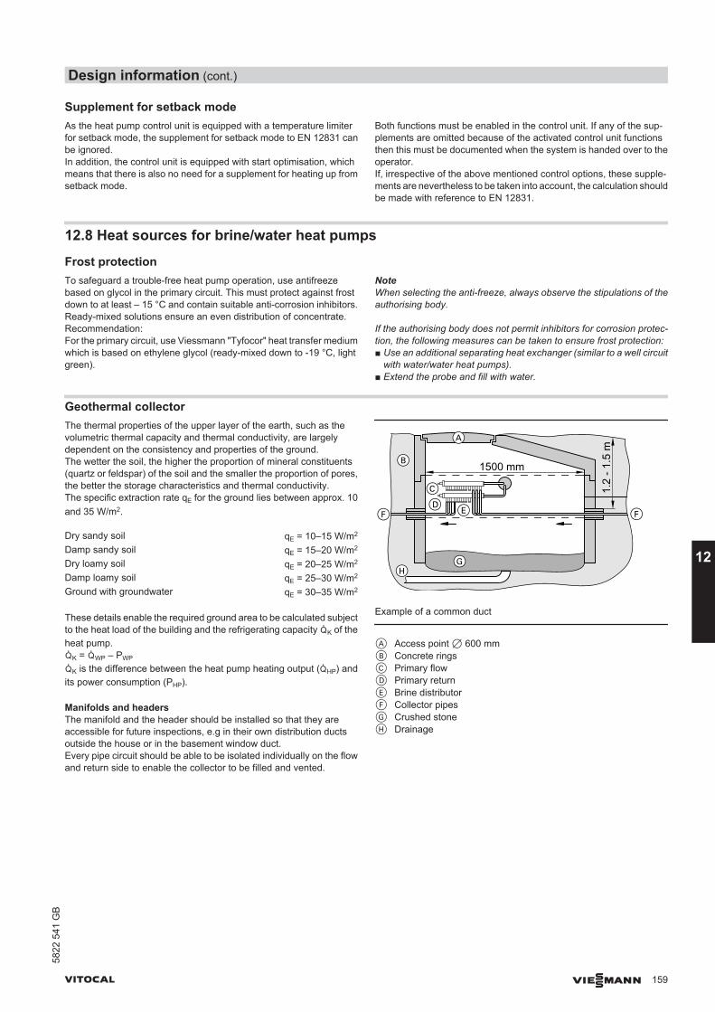
Supplement for setback modeAs the heat pump control unit is equipped with a temperature limiterfor setback mode, the supplement for setback mode to EN 12831 canbe ignored.In addition, the control unit is equipped with start optimisation, whichmeans that there is also no need for a supplement for heating up fromsetback mode.
Both functions must be enabled in the control unit. If any of the sup-plements are omitted because of the activated control unit functionsthen this must be documented when the system is handed over to theoperator.If, irrespective of the above mentioned control options, these supple-ments are nevertheless to be taken into account, the calculation shouldbe made with reference to EN 12831.
12.8 Heat sources for brine/water heat pumps
Frost protectionTo safeguard a trouble-free heat pump operation, use antifreezebased on glycol in the primary circuit. This must protect against frostdown to at least – 15 °C and contain suitable anti-corrosion inhibitors.Ready-mixed solutions ensure an even distribution of concentrate.Recommendation:For the primary circuit, use Viessmann "Tyfocor" heat transfer mediumwhich is based on ethylene glycol (ready-mixed down to -19 °C, lightgreen).
NoteWhen selecting the anti-freeze, always observe the stipulations of theauthorising body.
If the authorising body does not permit inhibitors for corrosion protec-tion, the following measures can be taken to ensure frost protection:■ Use an additional separating heat exchanger (similar to a well circuit
with water/water heat pumps).■ Extend the probe and fill with water.
Geothermal collectorThe thermal properties of the upper layer of the earth, such as thevolumetric thermal capacity and thermal conductivity, are largelydependent on the consistency and properties of the ground.The wetter the soil, the higher the proportion of mineral constituents(quartz or feldspar) of the soil and the smaller the proportion of pores,the better the storage characteristics and thermal conductivity.The specific extraction rate qE for the ground lies between approx. 10and 35 W/m2.
Dry sandy soil qE = 10–15 W/m2
Damp sandy soil qE = 15–20 W/m2
Dry loamy soil qE = 20–25 W/m2
Damp loamy soil qE = 25–30 W/m2
Ground with groundwater qE = 30–35 W/m2
These details enable the required ground area to be calculated subjectto the heat load of the building and the refrigerating capacity ²K of theheat pump.²K = ²WP – PWP
²K is the difference between the heat pump heating output (²HP) andits power consumption (PHP).
Manifolds and headersThe manifold and the header should be installed so that they areaccessible for future inspections, e.g in their own distribution ductsoutside the house or in the basement window duct.Every pipe circuit should be able to be isolated individually on the flowand return side to enable the collector to be filled and vented.
1500 mm
C
F FD E
A
B
GH
1.2
- 1.5
mExample of a common duct
A Access point 7 600 mmB Concrete ringsC Primary flowD Primary returnE Brine distributorF Collector pipesG Crushed stoneH Drainage
Design information (cont.)
VITOCAL VIESMANN 159
5822
541
GB
12
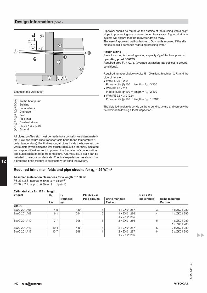
2°
Example of a wall outlet
A To the heat pumpB BuildingC FoundationsD DrainageE SealF Pipe linerG Crushed stoneH PE 32 × 3.0 (2.9)K Ground
All pipes, profiles etc. must be made from corrosion-resistant materi-als. Flow and return lines transport cold brine (brine temperature <cellar temperature). For that reason, all pipes inside the house and thewall outlets (even inside the wall structure) must be thermally insulatedand vapour diffusion-proof to prevent the formation of condensationand subsequent damage from moisture. Alternatively, a drain can beinstalled to remove condensate. Practical experience has shown thata prepared brine mixture is satisfactory for filling the system.
Pipework should be routed on the outside of the building with a slightslope to prevent ingress of water during heavy rain. A good drainagesystem will ensure that the rainwater drains away.The use of approved wall outlets (e.g. Doyma) is required if the sitemakes specific demands regarding pressing water.
Rough sizingBasis for sizing is the refrigerating capacity ²K of the heat pump atoperating point B0/W35.Required area FE = ²K/³E (average extraction rate subject to groundconditions).
Required number of pipe circuits @ 100 m length subject to FE and thepipe dimension:■ With PE 20 × 2.0:
Pipe circuits @ 100 m length = FE · 3/100■ With PE 25 × 2.3:
Pipe circuits @ 100 m length = FE · 2/100■ With PE 32 × 3.0 (2.9):
Pipe circuits @ 100 m length = FE · 1.5/100
The detailed design depends on the ground structure and can only bedetermined following a local inspection.
Required brine manifolds and pipe circuits for ³E = 25 W/m2
Assumed installation clearances for a length of 100 m:PE 25 x 2.3 approx. 0.50 m (2 m pipe/m2)PE 32 x 2.9 approx. 0.70 m (1 m pipe/m2)
Estimated size for 100 m lengthVitocal ²K FE PE 25 x 2.3 PE 32 x 2.9
(rounded) Pipe circuits Brine manifold Pipe circuits Brine manifoldkW m2 Part no. Part no.
200-GBWC 201.A06 4.5 180 4 1 x ZK01 287 3 1 x ZK01 289BWC 201.A08 6.1 244 5 1 x ZK01 286
1 x ZK01 2854 1 x ZK01 290
BWC 201.A10 7.7 308 6 2 x ZK01 286 5 1 x ZK01 2891 x ZK01 288
BWC 201.A13 10.4 416 8 2 x ZK01 287 6 2 x ZK01 289BWC 201.A17 13.7 548 11 2 x ZK01 287
1 x ZK01 2868 2 x ZK01 290
Design information (cont.)
160 VIESMANN VITOCAL
12
5822
541
GB
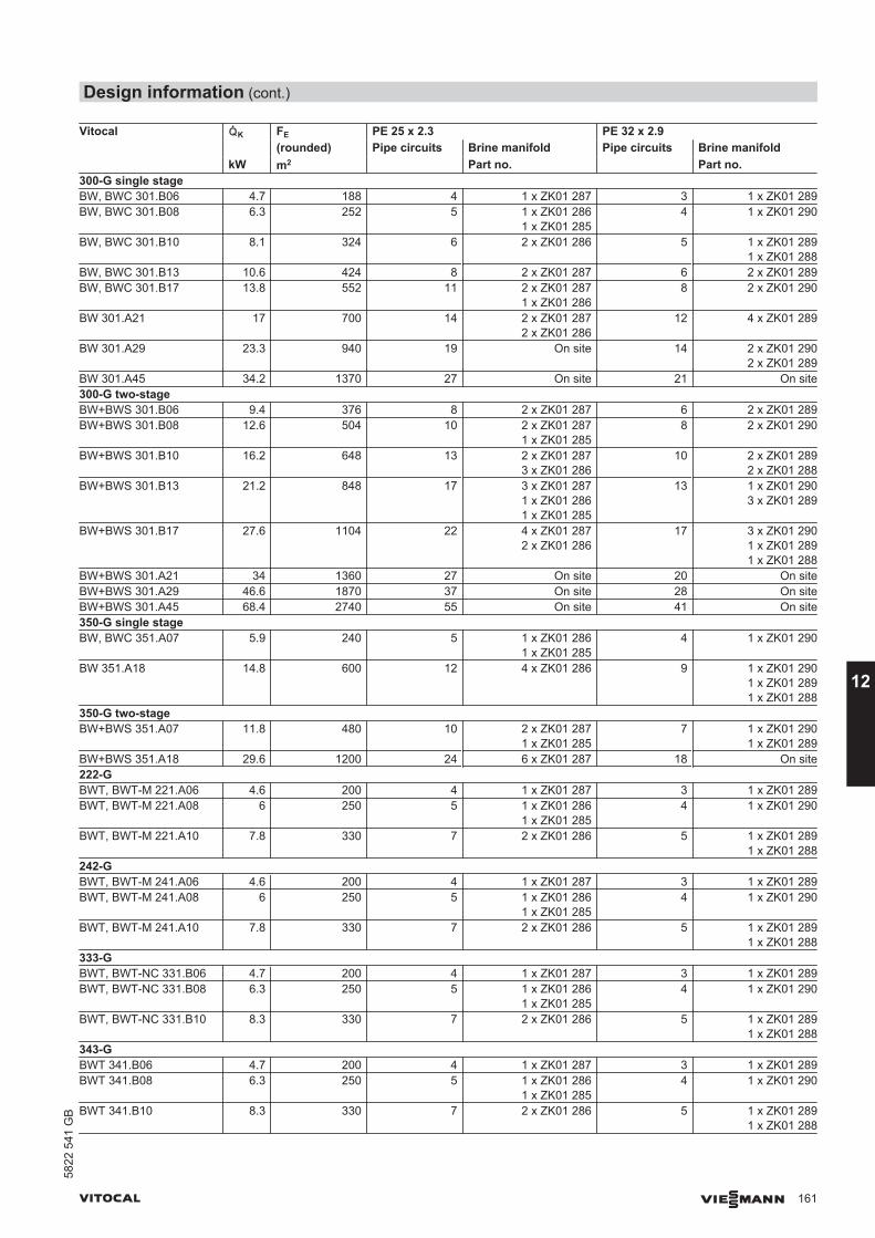
Vitocal ²K FE PE 25 x 2.3 PE 32 x 2.9(rounded) Pipe circuits Brine manifold Pipe circuits Brine manifold
kW m2 Part no. Part no.300-G single stageBW, BWC 301.B06 4.7 188 4 1 x ZK01 287 3 1 x ZK01 289BW, BWC 301.B08 6.3 252 5 1 x ZK01 286
1 x ZK01 2854 1 x ZK01 290
BW, BWC 301.B10 8.1 324 6 2 x ZK01 286 5 1 x ZK01 2891 x ZK01 288
BW, BWC 301.B13 10.6 424 8 2 x ZK01 287 6 2 x ZK01 289BW, BWC 301.B17 13.8 552 11 2 x ZK01 287
1 x ZK01 2868 2 x ZK01 290
BW 301.A21 17 700 14 2 x ZK01 2872 x ZK01 286
12 4 x ZK01 289
BW 301.A29 23.3 940 19 On site 14 2 x ZK01 2902 x ZK01 289
BW 301.A45 34.2 1370 27 On site 21 On site300-G two-stageBW+BWS 301.B06 9.4 376 8 2 x ZK01 287 6 2 x ZK01 289BW+BWS 301.B08 12.6 504 10 2 x ZK01 287
1 x ZK01 2858 2 x ZK01 290
BW+BWS 301.B10 16.2 648 13 2 x ZK01 2873 x ZK01 286
10 2 x ZK01 2892 x ZK01 288
BW+BWS 301.B13 21.2 848 17 3 x ZK01 2871 x ZK01 2861 x ZK01 285
13 1 x ZK01 2903 x ZK01 289
BW+BWS 301.B17 27.6 1104 22 4 x ZK01 2872 x ZK01 286
17 3 x ZK01 2901 x ZK01 2891 x ZK01 288
BW+BWS 301.A21 34 1360 27 On site 20 On siteBW+BWS 301.A29 46.6 1870 37 On site 28 On siteBW+BWS 301.A45 68.4 2740 55 On site 41 On site350-G single stageBW, BWC 351.A07 5.9 240 5 1 x ZK01 286
1 x ZK01 2854 1 x ZK01 290
BW 351.A18 14.8 600 12 4 x ZK01 286 9 1 x ZK01 2901 x ZK01 2891 x ZK01 288
350-G two-stageBW+BWS 351.A07 11.8 480 10 2 x ZK01 287
1 x ZK01 2857 1 x ZK01 290
1 x ZK01 289BW+BWS 351.A18 29.6 1200 24 6 x ZK01 287 18 On site222-GBWT, BWT-M 221.A06 4.6 200 4 1 x ZK01 287 3 1 x ZK01 289BWT, BWT-M 221.A08 6 250 5 1 x ZK01 286
1 x ZK01 2854 1 x ZK01 290
BWT, BWT-M 221.A10 7.8 330 7 2 x ZK01 286 5 1 x ZK01 2891 x ZK01 288
242-GBWT, BWT-M 241.A06 4.6 200 4 1 x ZK01 287 3 1 x ZK01 289BWT, BWT-M 241.A08 6 250 5 1 x ZK01 286
1 x ZK01 2854 1 x ZK01 290
BWT, BWT-M 241.A10 7.8 330 7 2 x ZK01 286 5 1 x ZK01 2891 x ZK01 288
333-GBWT, BWT-NC 331.B06 4.7 200 4 1 x ZK01 287 3 1 x ZK01 289BWT, BWT-NC 331.B08 6.3 250 5 1 x ZK01 286
1 x ZK01 2854 1 x ZK01 290
BWT, BWT-NC 331.B10 8.3 330 7 2 x ZK01 286 5 1 x ZK01 2891 x ZK01 288
343-GBWT 341.B06 4.7 200 4 1 x ZK01 287 3 1 x ZK01 289BWT 341.B08 6.3 250 5 1 x ZK01 286
1 x ZK01 2854 1 x ZK01 290
BWT 341.B10 8.3 330 7 2 x ZK01 286 5 1 x ZK01 2891 x ZK01 288
Design information (cont.)
VITOCAL VIESMANN 161
5822
541
GB
12
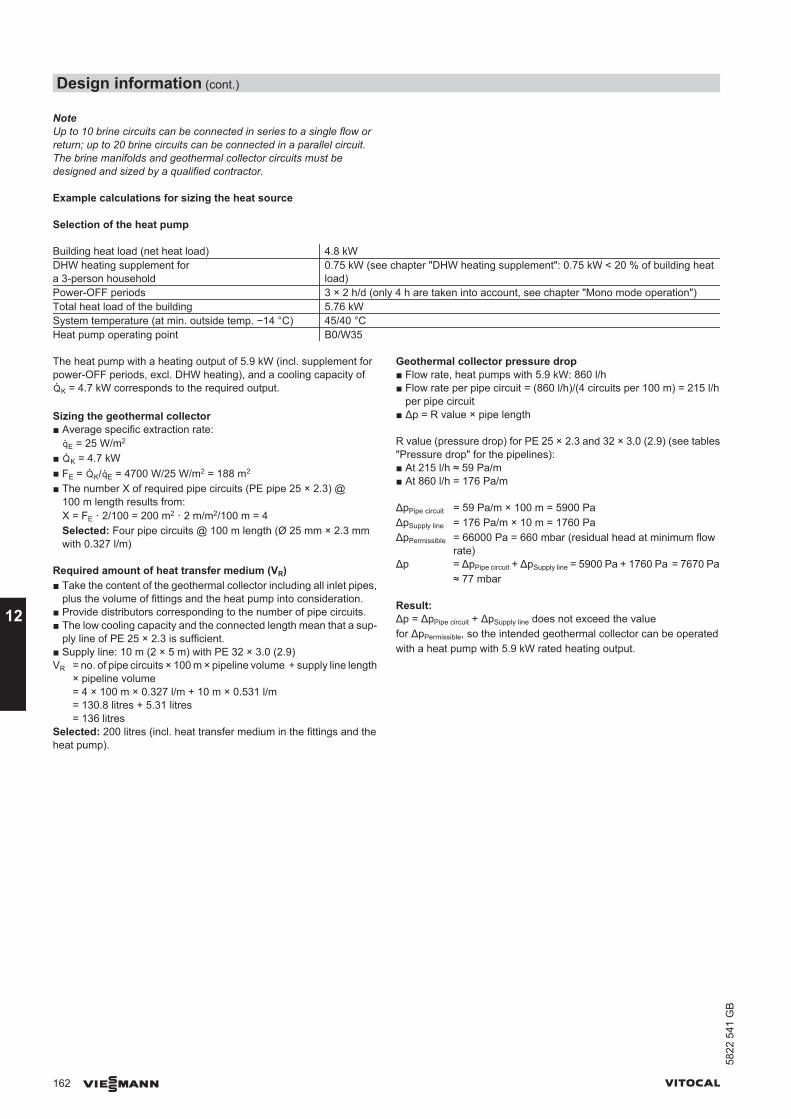
NoteUp to 10 brine circuits can be connected in series to a single flow orreturn; up to 20 brine circuits can be connected in a parallel circuit.The brine manifolds and geothermal collector circuits must bedesigned and sized by a qualified contractor.
Example calculations for sizing the heat source
Selection of the heat pump
Building heat load (net heat load) 4.8 kWDHW heating supplement fora 3-person household
0.75 kW (see chapter "DHW heating supplement": 0.75 kW < 20 % of building heatload)
Power-OFF periods 3 × 2 h/d (only 4 h are taken into account, see chapter "Mono mode operation")Total heat load of the building 5.76 kWSystem temperature (at min. outside temp. −14 °C) 45/40 °CHeat pump operating point B0/W35
The heat pump with a heating output of 5.9 kW (incl. supplement forpower-OFF periods, excl. DHW heating), and a cooling capacity of²K = 4.7 kW corresponds to the required output.
Sizing the geothermal collector■ Average specific extraction rate:
³E = 25 W/m2
■ ²K = 4.7 kW■ FE = ²K/³E = 4700 W/25 W/m2 = 188 m2
■ The number X of required pipe circuits (PE pipe 25 × 2.3) @100 m length results from:X = FE · 2/100 = 200 m2 · 2 m/m2/100 m = 4Selected: Four pipe circuits @ 100 m length (Ø 25 mm × 2.3 mmwith 0.327 l/m)
Required amount of heat transfer medium (VR)■ Take the content of the geothermal collector including all inlet pipes,
plus the volume of fittings and the heat pump into consideration.■ Provide distributors corresponding to the number of pipe circuits.■ The low cooling capacity and the connected length mean that a sup-
ply line of PE 25 × 2.3 is sufficient.■ Supply line: 10 m (2 × 5 m) with PE 32 × 3.0 (2.9)VR = no. of pipe circuits × 100 m × pipeline volume + supply line length
× pipeline volume= 4 × 100 m × 0.327 l/m + 10 m × 0.531 l/m= 130.8 litres + 5.31 litres= 136 litres
Selected: 200 litres (incl. heat transfer medium in the fittings and theheat pump).
Geothermal collector pressure drop■ Flow rate, heat pumps with 5.9 kW: 860 l/h■ Flow rate per pipe circuit = (860 l/h)/(4 circuits per 100 m) = 215 l/h
per pipe circuit■ Δp = R value × pipe length
R value (pressure drop) for PE 25 × 2.3 and 32 × 3.0 (2.9) (see tables"Pressure drop" for the pipelines):■ At 215 l/h ≈ 59 Pa/m■ At 860 l/h = 176 Pa/m
ΔpPipe circuit = 59 Pa/m × 100 m = 5900 PaΔpSupply line = 176 Pa/m × 10 m = 1760 PaΔpPermissible = 66000 Pa = 660 mbar (residual head at minimum flow
rate)Δp = ΔpPipe circuit + ΔpSupply line = 5900 Pa + 1760 Pa = 7670 Pa
≈ 77 mbar
Result:Δp = ΔpPipe circuit + ΔpSupply line does not exceed the valuefor ΔpPermissible, so the intended geothermal collector can be operatedwith a heat pump with 5.9 kW rated heating output.
Design information (cont.)
162 VIESMANN VITOCAL
12
5822
541
GB
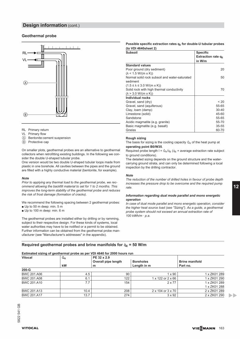
Geothermal probe
RL
VL
RL Primary returnVL Primary flowA Bentonite:cement suspensionB Protective cap
On smaller plots, geothermal probes are an alternative to geothermalcollectors when retrofitting existing buildings. In the following we con-sider the double U-shaped tubular probe.One version would be two double U-shaped tubular loops made fromplastic in one borehole. All cavities between the pipes and the groundare filled with a highly conductive material (bentonite, for example).
NotePrior to applying any thermal load to the geothermal probe, we rec-ommend allowing the backfill material to set for 1 to 2 months. Thisimproves the long-term stability of the geothermal probe and reducesthe risk of frost damage (formation of cracks).
We recommend the following spacing between 2 geothermal probes:■ Up to 50 m deep: min. 5 m■ Up to 100 m deep: min. 6 m
The geothermal probes are installed either by drilling or by ramming,subject to their respective design. For these kinds of systems, localwater authorities may have to be notified or a permit to be obtained.Further information can be obtained from the geothermal probe man-ufacturer (see "Manufacturer's addresses" in the appendix).
Possible specific extraction rates qE for double-U tubular probes(to VDI 4640sheet 2)Subsoil Specific
Extraction rate qE
in W/mStandard values Poor ground (dry sediment)(λ < 1.5 W/(m x K))
20
Normal solid rock subsoil and water-saturatedsediment(1.5 ≤ λ ≤ 3.0 W/(m x K))
50
Solid rock with high thermal conductivity(λ > 3.0 W/(m x K))
70
Individual rocks Gravel, sand (dry) < 20Gravel, sand (aquiferous) 55-65Clay, loam (damp) 30-40Limestone (solid) 45-60Sandstone 55-65Acidic magmatite (e.g. granite) 55-70Basic magmatite (e.g. basalt) 35-55Gneiss 60-70
Rough sizingThe basis for sizing is the cooling capacity ²K of the heat pump atoperating point B0/W35.Required probe length l = ²K/³E (³E = average extraction rate subjectto ground conditions).The detailed sizing depends on the ground structure and the water-carrying ground strata, and can only be determined following a localinspection by the drilling contractor.
NoteThe reduction of the number of drilled holes in favour of probe depthincreases the pressure drop to be overcome and the required pumprate.
Information regarding dual mode parallel and mono energeticoperationIn case of dual mode parallel and mono energetic operation, considerthe higher heat source load (see "Sizing"). As a guide, a geothermalprobe system should not exceed an annual extraction rate of100 kWh/m ∙ p.a.
Required geothermal probes and brine manifolds for ³E = 50 W/m
Estimated sizing of geothermal probe as per VDI 4640 for 2000 hours runVitocal ²K PE 32 x 2.9
Overall pipe length Boreholes Brine manifoldkW m Length in m Part no.
200-GBWC 201.A06 4.5 90 1 x 90 1 x ZK01 289BWC 201.A08 6.1 122 1 x 122 or 2 x 66 1 x ZK01 290BWC 201.A10 7.7 154 2 x 77 1 x ZK01 289
1 x ZK01 288BWC 201.A13 10.4 208 2 x 10⁴ or 3 x 70 2 x ZK01 289BWC 201.A17 13.7 274 3 x 92 2 x ZK01 290
Design information (cont.)
VITOCAL VIESMANN 163
5822
541
GB
12
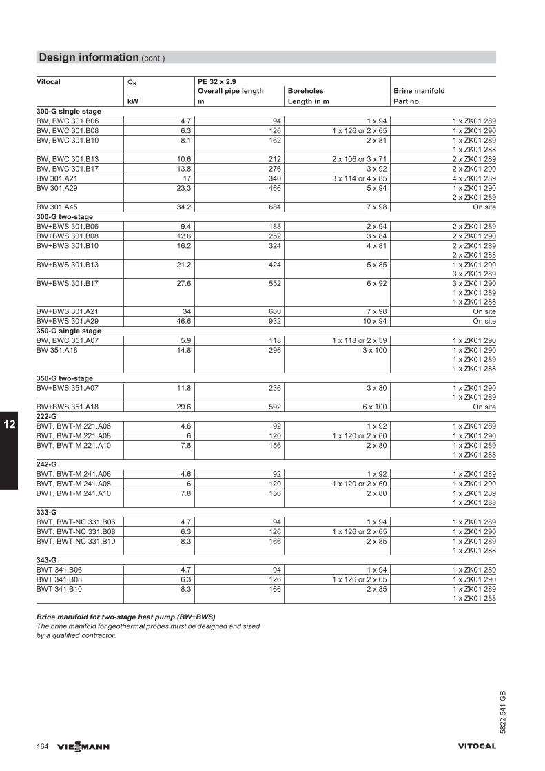
Vitocal ²K PE 32 x 2.9 Overall pipe length Boreholes Brine manifold
kW m Length in m Part no.300-G single stageBW, BWC 301.B06 4.7 94 1 x 94 1 x ZK01 289BW, BWC 301.B08 6.3 126 1 x 126 or 2 x 65 1 x ZK01 290BW, BWC 301.B10 8.1 162 2 x 81 1 x ZK01 289
1 x ZK01 288BW, BWC 301.B13 10.6 212 2 x 10⁶ or 3 x 71 2 x ZK01 289BW, BWC 301.B17 13.8 276 3 x 92 2 x ZK01 290BW 301.A21 17 340 3 x 114 or 4 x 85 4 x ZK01 289BW 301.A29 23.3 466 5 x 94 1 x ZK01 290
2 x ZK01 289BW 301.A45 34.2 684 7 x 98 On site300-G two-stageBW+BWS 301.B06 9.4 188 2 x 94 2 x ZK01 289BW+BWS 301.B08 12.6 252 3 x 84 2 x ZK01 290BW+BWS 301.B10 16.2 324 4 x 81 2 x ZK01 289
2 x ZK01 288BW+BWS 301.B13 21.2 424 5 x 85 1 x ZK01 290
3 x ZK01 289BW+BWS 301.B17 27.6 552 6 x 92 3 x ZK01 290
1 x ZK01 2891 x ZK01 288
BW+BWS 301.A21 34 680 7 x 98 On siteBW+BWS 301.A29 46.6 932 10 x 94 On site350-G single stageBW, BWC 351.A07 5.9 118 1 x 118 or 2 x 59 1 x ZK01 290BW 351.A18 14.8 296 3 x 100 1 x ZK01 290
1 x ZK01 2891 x ZK01 288
350-G two-stageBW+BWS 351.A07 11.8 236 3 x 80 1 x ZK01 290
1 x ZK01 289BW+BWS 351.A18 29.6 592 6 x 100 On site222-GBWT, BWT-M 221.A06 4.6 92 1 x 92 1 x ZK01 289BWT, BWT-M 221.A08 6 120 1 x 120 or 2 x 60 1 x ZK01 290BWT, BWT-M 221.A10 7.8 156 2 x 80 1 x ZK01 289
1 x ZK01 288242-GBWT, BWT-M 241.A06 4.6 92 1 x 92 1 x ZK01 289BWT, BWT-M 241.A08 6 120 1 x 120 or 2 x 60 1 x ZK01 290BWT, BWT-M 241.A10 7.8 156 2 x 80 1 x ZK01 289
1 x ZK01 288333-GBWT, BWT-NC 331.B06 4.7 94 1 x 94 1 x ZK01 289BWT, BWT-NC 331.B08 6.3 126 1 x 126 or 2 x 65 1 x ZK01 290BWT, BWT-NC 331.B10 8.3 166 2 x 85 1 x ZK01 289
1 x ZK01 288343-GBWT 341.B06 4.7 94 1 x 94 1 x ZK01 289BWT 341.B08 6.3 126 1 x 126 or 2 x 65 1 x ZK01 290BWT 341.B10 8.3 166 2 x 85 1 x ZK01 289
1 x ZK01 288
Brine manifold for two-stage heat pump (BW+BWS)The brine manifold for geothermal probes must be designed and sizedby a qualified contractor.
Design information (cont.)
164 VIESMANN VITOCAL
12
5822
541
GB
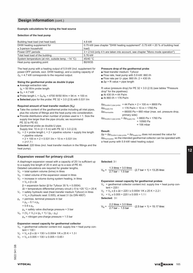
Example calculations for sizing the heat source
Selection of the heat pump
Building heat load (net heat load) 4.8 kWDHW heating supplement fora 3-person household
0.75 kW (see chapter "DHW heating supplement": 0.75 kW < 20 % of building heatload)
Power-OFF periods 3 × 2 h/d (only 4 h are taken into account, see chapter "Mono mode operation")Total heat load of the building 5.76 kWSystem temperature (at min. outside temp. −14 °C) 45/40 °CHeat pump operating point B0/W35
The heat pump with a heating output of 5.9 kW (incl. supplement forpower-OFF periods, excl. DHW heating), and a cooling capacity of²K = 4.7 kW corresponds to the required output.
Sizing the geothermal probe as double U-pipe■ Average extraction rate:
³E = 50 W/m probe length■ ²K = 4.7 kW■ Probe length L = ²K/³E = 4700 W/50 W/m = 94 m ≈ 100 m■ Selected pipe for the probe: PE 32 × 3.0 (2.9) with 0.531 l/m
Required amount of heat transfer medium (VR)■ Take the content of the geothermal probe including all inlet pipes,
plus the volume of fittings and the heat pump into consideration.■ Provide distributors when number of probes used is > 1. Size the
supply line larger than the pipe circuits; we recommendPE 32 to PE 63.
■ Geothermal probe as double-U pipe.Supply line: 10 m (2 × 5 m) with PE 32 × 3.0 (2.9)
VR = 2 × probe length L × 2 × pipeline volume + supply line length× pipeline volume= 2 × 100 m × 2 × 0.531 l/m + 10 m × 0.531 l/m= 217.7 l
Selected: 220 litres (incl. heat transfer medium in the fittings and theheat pump).
Pressure drop of the geothermal probe■ Heat transfer medium: Tyfocor■ Flow rate, heat pump with 5.9 kW: 860 l/h■ Flow rate per U- pipe: 860 l/h: 2 = 430 l/h■ Δp = R value × pipe length
R value (pressure drop) for PE 32 × 3.0 (2.9) (see tables "Pressuredrop" for the pipelines):■ At 430 l/h ≈ 44 Pa/m■ At 860 l/h = 176 Pa/m
ΔpDouble-U pipe probe = 44 Pa/m × 2 × 100 m = 8800 PaΔpSupply line = 176 Pa/m × 10 m = 1760 PaΔpPermissible = 66000 Pa = 660 mbar (max. ext. pressure drop,
primary side)ΔpDouble-U pipe probe + ΔpSupply line = 8800 Pa + 1760 Pa
= 10560 Pa≈ 106 mbar
Result:Δp = ΔpDouble-U pipe probe + ΔpSupply line does not exceed the value forΔpPermissible, so the intended geothermal collector can be operated witha heat pump with 5.9 kW rated heating output.
Expansion vessel for primary circuitA diaphragm expansion vessel with a capacity of 25 l is sufficient upto a supply line length of 20 m and up to a size of PE 40.Detailed calculations are required for greater lengths.VA = total system volume (brine) in litresVN = rated volume of the expansion vessel in litresVZ = increase in volume during system heating, in litres
= VA x β x Δtβ = expansion factor (β for Tyfocor 35 % = 0.0004)Δt = temperature differential primary circuit (–5 to +20 °C) = 25 K
VV = safety hydraulic seal (heat transfer medium Tyfocor) in litres= VA x (hydraulic seal: 0.005), at least 3 l (to DIN 4807)
pe = permiss. terminal pressure in bar= psi – 0.1 x psi
= 0.9 x psi
psi = safety valve discharge pressure = 3 barVN = (VZ + VV) x (pe + 1) / (pe - pst)
pst = nitrogen pre-charge pressure = 1.5 bar
Expansion vessel capacity for geothermal collectorVA = geothermal collector content incl. supply line + heat pump con-
tent = 130 lVZ = VA x β x Δt = 130 l x 0.0004 1/K x 25 K = 1.3 lVV = VA x 0.005 = 130 l x 0.005 = 0.65 l
Selected: 3 l
1.3 litres + 3.0 litres2.7 bar – 1.5 bar · (2.7 bar + 1) = 13.25 litresVN =
Expansion vessel capacity for geothermal probesVA = geothermal collector content incl. supply line + heat pump con-
tent = 220 lVZ = VA x β x Δt = 220 l x 0.0004 1/K x 25 K = 2.2 lVV = VA x 0.005 = 220 l x 0.005 = 1.1 lSelected: 3 l
2.2 litres + 3.0 litres2.7 bar – 1.5 bar · (2.5 bar + 1) = 15.17 litresVN =
Design information (cont.)
VITOCAL VIESMANN 165
5822
541
GB
12
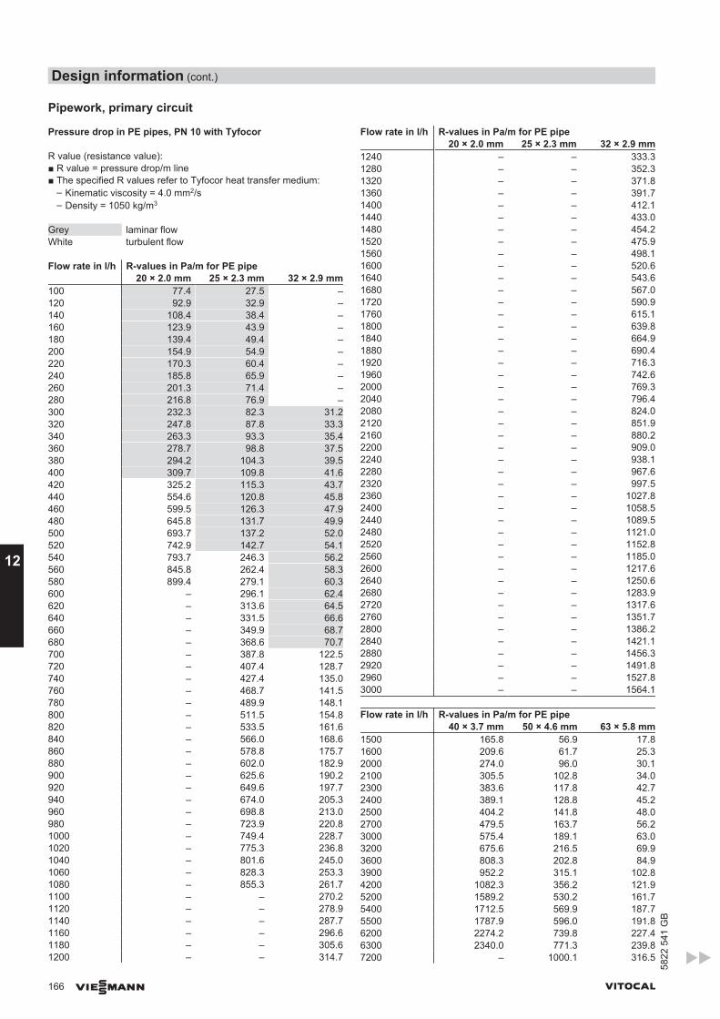
Pipework, primary circuit
Pressure drop in PE pipes, PN 10 with Tyfocor
R value (resistance value):■ R value = pressure drop/m line■ The specified R values refer to Tyfocor heat transfer medium:
– Kinematic viscosity = 4.0 mm2/s– Density = 1050 kg/m3
Grey laminar flowWhite turbulent flow
Flow rate in l/h R-values in Pa/m for PE pipe20 × 2.0 mm 25 × 2.3 mm 32 × 2.9 mm
100 77.4 27.5 –120 92.9 32.9 –140 108.4 38.4 –160 123.9 43.9 –180 139.4 49.4 –200 154.9 54.9 –220 170.3 60.4 –240 185.8 65.9 –260 201.3 71.4 –280 216.8 76.9 –300 232.3 82.3 31.2320 247.8 87.8 33.3340 263.3 93.3 35.4360 278.7 98.8 37.5380 294.2 104.3 39.5400 309.7 109.8 41.6420 325.2 115.3 43.7440 554.6 120.8 45.8460 599.5 126.3 47.9480 645.8 131.7 49.9500 693.7 137.2 52.0520 742.9 142.7 54.1540 793.7 246.3 56.2560 845.8 262.4 58.3580 899.4 279.1 60.3600 – 296.1 62.4620 – 313.6 64.5640 – 331.5 66.6660 – 349.9 68.7680 – 368.6 70.7700 – 387.8 122.5720 – 407.4 128.7740 – 427.4 135.0760 – 468.7 141.5780 – 489.9 148.1800 – 511.5 154.8820 – 533.5 161.6840 – 566.0 168.6860 – 578.8 175.7880 – 602.0 182.9900 – 625.6 190.2920 – 649.6 197.7940 – 674.0 205.3960 – 698.8 213.0980 – 723.9 220.81000 – 749.4 228.71020 – 775.3 236.81040 – 801.6 245.01060 – 828.3 253.31080 – 855.3 261.71100 – – 270.21120 – – 278.91140 – – 287.71160 – – 296.61180 – – 305.61200 – – 314.7
Flow rate in l/h R-values in Pa/m for PE pipe20 × 2.0 mm 25 × 2.3 mm 32 × 2.9 mm
1240 – – 333.31280 – – 352.31320 – – 371.81360 – – 391.71400 – – 412.11440 – – 433.01480 – – 454.21520 – – 475.91560 – – 498.11600 – – 520.61640 – – 543.61680 – – 567.01720 – – 590.91760 – – 615.11800 – – 639.81840 – – 664.91880 – – 690.41920 – – 716.31960 – – 742.62000 – – 769.32040 – – 796.42080 – – 824.02120 – – 851.92160 – – 880.22200 – – 909.02240 – – 938.12280 – – 967.62320 – – 997.52360 – – 1027.82400 – – 1058.52440 – – 1089.52480 – – 1121.02520 – – 1152.82560 – – 1185.02600 – – 1217.62640 – – 1250.62680 – – 1283.92720 – – 1317.62760 – – 1351.72800 – – 1386.22840 – – 1421.12880 – – 1456.32920 – – 1491.82960 – – 1527.83000 – – 1564.1
Flow rate in l/h R-values in Pa/m for PE pipe40 × 3.7 mm 50 × 4.6 mm 63 × 5.8 mm
1500 165.8 56.9 17.81600 209.6 61.7 25.32000 274.0 96.0 30.12100 305.5 102.8 34.02300 383.6 117.8 42.72400 389.1 128.8 45.22500 404.2 141.8 48.02700 479.5 163.7 56.23000 575.4 189.1 63.03200 675.6 216.5 69.93600 808.3 202.8 84.93900 952.2 315.1 102.84200 1082.3 356.2 121.95200 1589.2 530.2 161.75400 1712.5 569.9 187.75500 1787.9 596.0 191.86200 2274.2 739.8 227.46300 2340.0 771.3 239.87200 – 1000.1 316.5
Design information (cont.)
166 VIESMANN VITOCAL
12
5822
541
GB
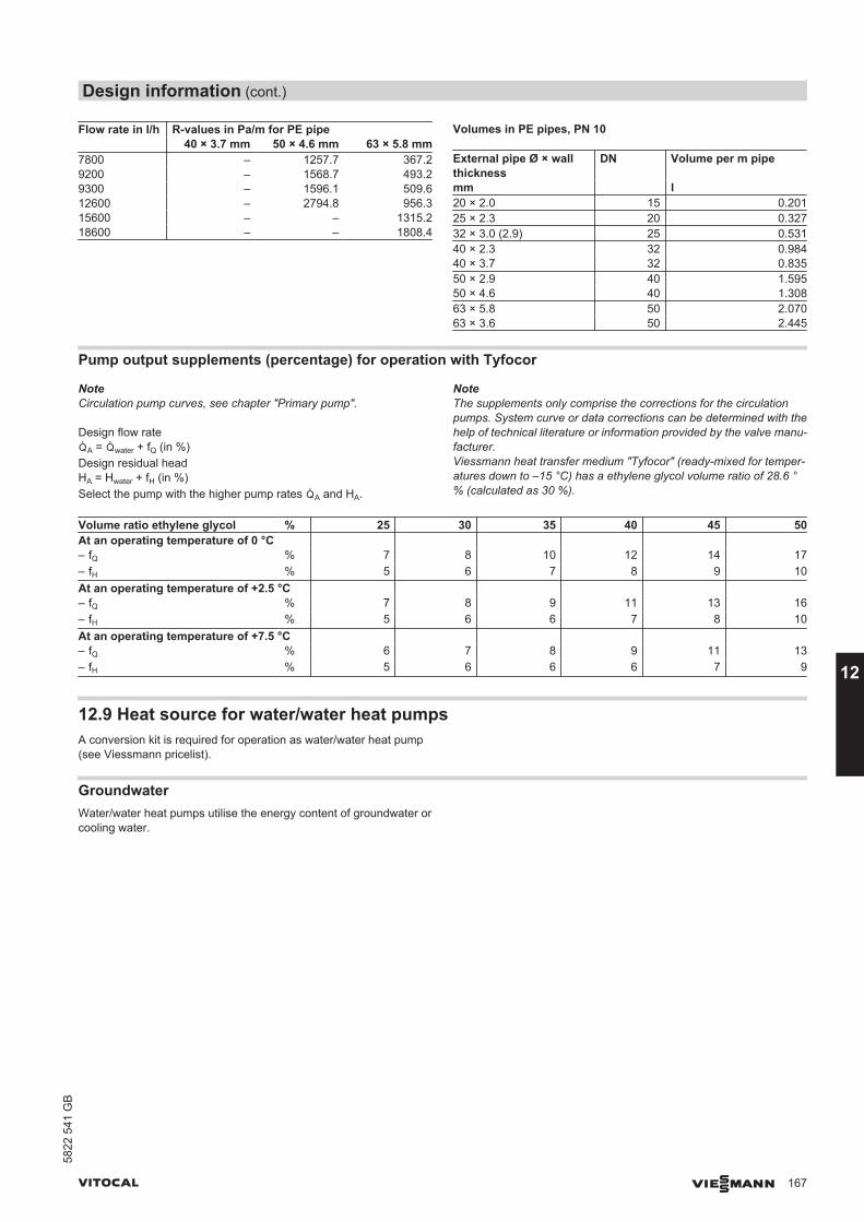
Flow rate in l/h R-values in Pa/m for PE pipe40 × 3.7 mm 50 × 4.6 mm 63 × 5.8 mm
7800 – 1257.7 367.29200 – 1568.7 493.29300 – 1596.1 509.612600 – 2794.8 956.315600 – – 1315.218600 – – 1808.4
Volumes in PE pipes, PN 10
External pipe Ø × wallthickness
DN Volume per m pipe
mm l20 × 2.0 15 0.20125 × 2.3 20 0.32732 × 3.0 (2.9) 25 0.53140 × 2.3 32 0.98440 × 3.7 32 0.83550 × 2.9 40 1.59550 × 4.6 40 1.30863 × 5.8 50 2.07063 × 3.6 50 2.445
Pump output supplements (percentage) for operation with Tyfocor
NoteCirculation pump curves, see chapter "Primary pump".
Design flow rate²A = ²water + fQ (in %)Design residual headHA = Hwater + fH (in %)Select the pump with the higher pump rates ²A and HA.
NoteThe supplements only comprise the corrections for the circulationpumps. System curve or data corrections can be determined with thehelp of technical literature or information provided by the valve manu-facturer.Viessmann heat transfer medium "Tyfocor" (ready-mixed for temper-atures down to –15 °C) has a ethylene glycol volume ratio of 28.6 °% (calculated as 30 %).
Volume ratio ethylene glycol % 25 30 35 40 45 50At an operating temperature of 0 °C – fQ % 7 8 10 12 14 17– fH % 5 6 7 8 9 10At an operating temperature of +2.5 °C – fQ % 7 8 9 11 13 16– fH % 5 6 6 7 8 10At an operating temperature of +7.5 °C – fQ % 6 7 8 9 11 13– fH % 5 6 6 6 7 9
12.9 Heat source for water/water heat pumpsA conversion kit is required for operation as water/water heat pump(see Viessmann pricelist).
GroundwaterWater/water heat pumps utilise the energy content of groundwater orcooling water.
Design information (cont.)
VITOCAL VIESMANN 167
5822
541
GB
12
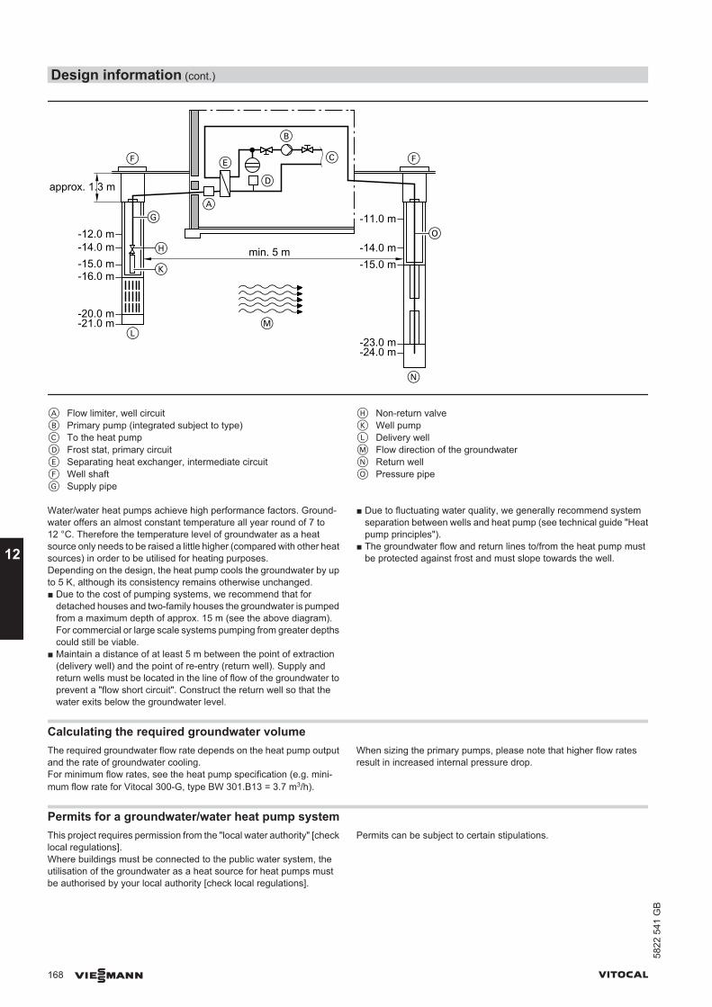
D
B
D
H
F
K
LM
O
N
G
E F
A
-14.0 mmin. 5 m-12.0 m-14.0 m-15.0 m-16.0 m
-20.0 m-21.0 m
-23.0 m-24.0 m
-15.0 m
-11.0 m
approx. 1.3 m
C
A Flow limiter, well circuitB Primary pump (integrated subject to type)C To the heat pumpD Frost stat, primary circuitE Separating heat exchanger, intermediate circuitF Well shaftG Supply pipe
H Non-return valveK Well pumpL Delivery wellM Flow direction of the groundwaterN Return wellO Pressure pipe
Water/water heat pumps achieve high performance factors. Ground-water offers an almost constant temperature all year round of 7 to12 °C. Therefore the temperature level of groundwater as a heatsource only needs to be raised a little higher (compared with other heatsources) in order to be utilised for heating purposes.Depending on the design, the heat pump cools the groundwater by upto 5 K, although its consistency remains otherwise unchanged.■ Due to the cost of pumping systems, we recommend that for
detached houses and two-family houses the groundwater is pumpedfrom a maximum depth of approx. 15 m (see the above diagram).For commercial or large scale systems pumping from greater depthscould still be viable.
■ Maintain a distance of at least 5 m between the point of extraction(delivery well) and the point of re-entry (return well). Supply andreturn wells must be located in the line of flow of the groundwater toprevent a "flow short circuit". Construct the return well so that thewater exits below the groundwater level.
■ Due to fluctuating water quality, we generally recommend systemseparation between wells and heat pump (see technical guide "Heatpump principles").
■ The groundwater flow and return lines to/from the heat pump mustbe protected against frost and must slope towards the well.
Calculating the required groundwater volumeThe required groundwater flow rate depends on the heat pump outputand the rate of groundwater cooling.For minimum flow rates, see the heat pump specification (e.g. mini-mum flow rate for Vitocal 300-G, type BW 301.B13 = 3.7 m3/h).
When sizing the primary pumps, please note that higher flow ratesresult in increased internal pressure drop.
Permits for a groundwater/water heat pump systemThis project requires permission from the "local water authority" [checklocal regulations]. Where buildings must be connected to the public water system, theutilisation of the groundwater as a heat source for heat pumps mustbe authorised by your local authority [check local regulations].
Permits can be subject to certain stipulations.
Design information (cont.)
168 VIESMANN VITOCAL
12
5822
541
GB
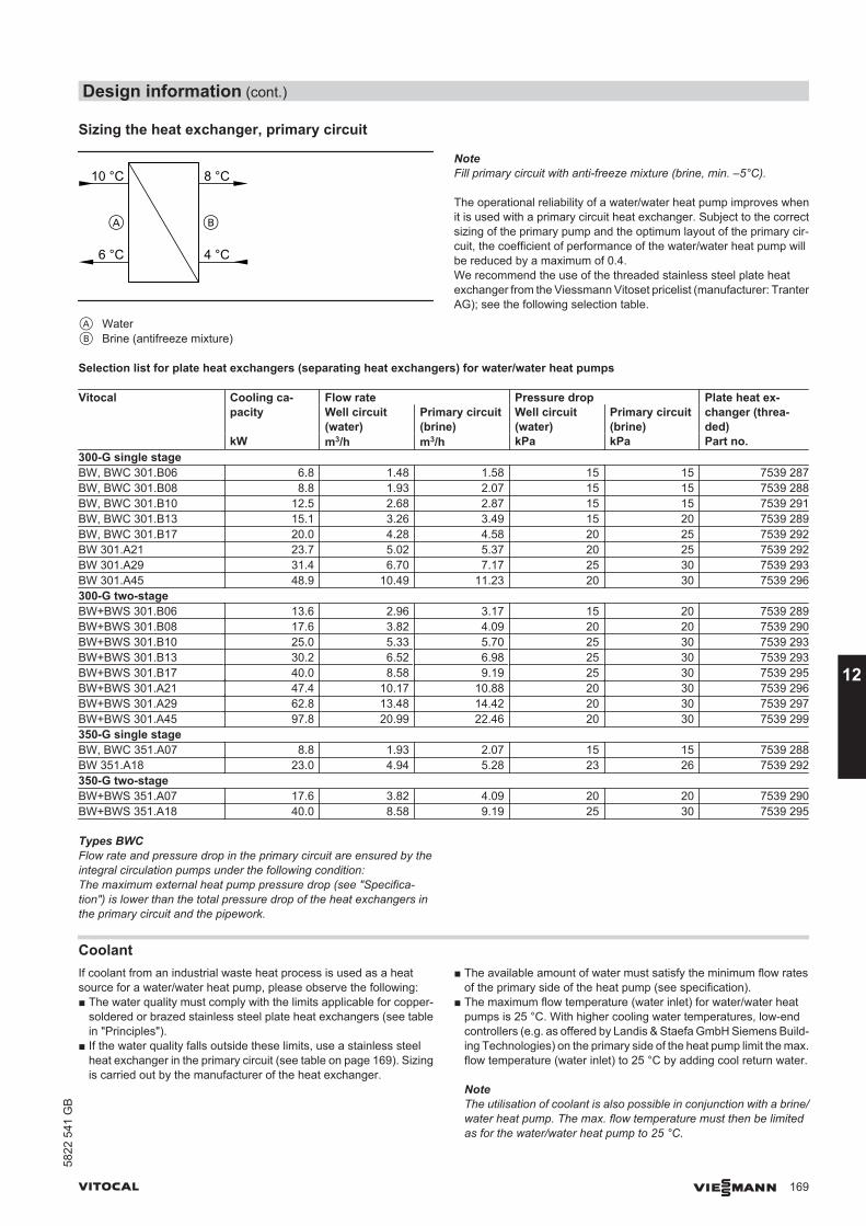
Sizing the heat exchanger, primary circuit
8 °C
6 °C 4 °C
10 °C
A B
A WaterB Brine (antifreeze mixture)
NoteFill primary circuit with anti-freeze mixture (brine, min. –5°C).
The operational reliability of a water/water heat pump improves whenit is used with a primary circuit heat exchanger. Subject to the correctsizing of the primary pump and the optimum layout of the primary cir-cuit, the coefficient of performance of the water/water heat pump willbe reduced by a maximum of 0.4.We recommend the use of the threaded stainless steel plate heatexchanger from the Viessmann Vitoset pricelist (manufacturer: TranterAG); see the following selection table.
Selection list for plate heat exchangers (separating heat exchangers) for water/water heat pumps
Vitocal Cooling ca-pacity
Flow rate Pressure drop Plate heat ex-changer (threa-ded)
Well circuit(water)
Primary circuit(brine)
Well circuit(water)
Primary circuit(brine)
kW m3/h m3/h kPa kPa Part no.300-G single stageBW, BWC 301.B06 6.8 1.48 1.58 15 15 7539 287BW, BWC 301.B08 8.8 1.93 2.07 15 15 7539 288BW, BWC 301.B10 12.5 2.68 2.87 15 15 7539 291BW, BWC 301.B13 15.1 3.26 3.49 15 20 7539 289BW, BWC 301.B17 20.0 4.28 4.58 20 25 7539 292BW 301.A21 23.7 5.02 5.37 20 25 7539 292BW 301.A29 31.4 6.70 7.17 25 30 7539 293BW 301.A45 48.9 10.49 11.23 20 30 7539 296300-G two-stageBW+BWS 301.B06 13.6 2.96 3.17 15 20 7539 289BW+BWS 301.B08 17.6 3.82 4.09 20 20 7539 290BW+BWS 301.B10 25.0 5.33 5.70 25 30 7539 293BW+BWS 301.B13 30.2 6.52 6.98 25 30 7539 293BW+BWS 301.B17 40.0 8.58 9.19 25 30 7539 295BW+BWS 301.A21 47.4 10.17 10.88 20 30 7539 296BW+BWS 301.A29 62.8 13.48 14.42 20 30 7539 297BW+BWS 301.A45 97.8 20.99 22.46 20 30 7539 299350-G single stageBW, BWC 351.A07 8.8 1.93 2.07 15 15 7539 288BW 351.A18 23.0 4.94 5.28 23 26 7539 292350-G two-stageBW+BWS 351.A07 17.6 3.82 4.09 20 20 7539 290BW+BWS 351.A18 40.0 8.58 9.19 25 30 7539 295
Types BWCFlow rate and pressure drop in the primary circuit are ensured by theintegral circulation pumps under the following condition:The maximum external heat pump pressure drop (see "Specifica-tion") is lower than the total pressure drop of the heat exchangers inthe primary circuit and the pipework.
CoolantIf coolant from an industrial waste heat process is used as a heatsource for a water/water heat pump, please observe the following:■ The water quality must comply with the limits applicable for copper-
soldered or brazed stainless steel plate heat exchangers (see tablein "Principles").
■ If the water quality falls outside these limits, use a stainless steelheat exchanger in the primary circuit (see table on page 169). Sizingis carried out by the manufacturer of the heat exchanger.
■ The available amount of water must satisfy the minimum flow ratesof the primary side of the heat pump (see specification).
■ The maximum flow temperature (water inlet) for water/water heatpumps is 25 °C. With higher cooling water temperatures, low-endcontrollers (e.g. as offered by Landis & Staefa GmbH Siemens Build-ing Technologies) on the primary side of the heat pump limit the max.flow temperature (water inlet) to 25 °C by adding cool return water.
NoteThe utilisation of coolant is also possible in conjunction with a brine/water heat pump. The max. flow temperature must then be limitedas for the water/water heat pump to 25 °C.
Design information (cont.)
VITOCAL VIESMANN 169
5822
541
GB
12
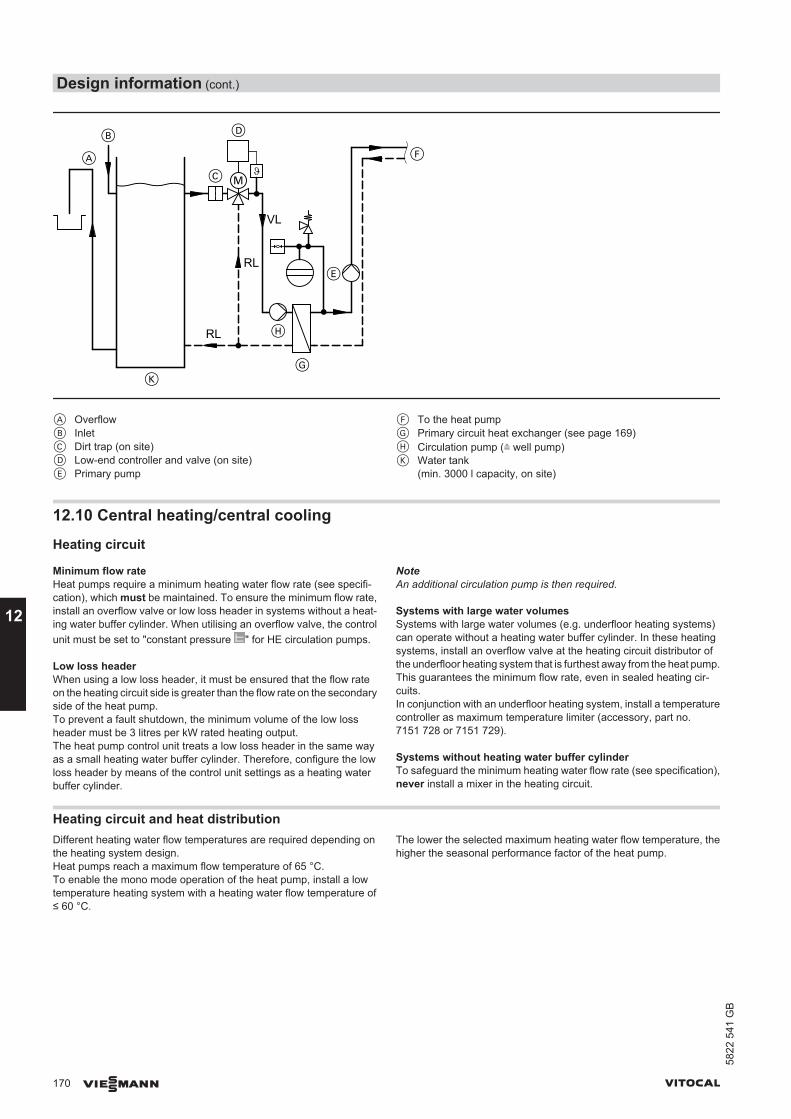
RL
VL
RL
A
B
C
D
K
H
G
E
F
A OverflowB InletC Dirt trap (on site)D Low-end controller and valve (on site)E Primary pump
F To the heat pumpG Primary circuit heat exchanger (see page 169)H Circulation pump (≙ well pump)K Water tank
(min. 3000 l capacity, on site)
12.10 Central heating/central cooling
Heating circuit
Minimum flow rateHeat pumps require a minimum heating water flow rate (see specifi-cation), which must be maintained. To ensure the minimum flow rate,install an overflow valve or low loss header in systems without a heat-ing water buffer cylinder. When utilising an overflow valve, the controlunit must be set to "constant pressure " for HE circulation pumps.
Low loss headerWhen using a low loss header, it must be ensured that the flow rateon the heating circuit side is greater than the flow rate on the secondaryside of the heat pump.To prevent a fault shutdown, the minimum volume of the low lossheader must be 3 litres per kW rated heating output.The heat pump control unit treats a low loss header in the same wayas a small heating water buffer cylinder. Therefore, configure the lowloss header by means of the control unit settings as a heating waterbuffer cylinder.
NoteAn additional circulation pump is then required.
Systems with large water volumesSystems with large water volumes (e.g. underfloor heating systems)can operate without a heating water buffer cylinder. In these heatingsystems, install an overflow valve at the heating circuit distributor ofthe underfloor heating system that is furthest away from the heat pump.This guarantees the minimum flow rate, even in sealed heating cir-cuits.In conjunction with an underfloor heating system, install a temperaturecontroller as maximum temperature limiter (accessory, part no.7151 728 or 7151 729).
Systems without heating water buffer cylinderTo safeguard the minimum heating water flow rate (see specification),never install a mixer in the heating circuit.
Heating circuit and heat distributionDifferent heating water flow temperatures are required depending onthe heating system design.Heat pumps reach a maximum flow temperature of 65 °C.To enable the mono mode operation of the heat pump, install a lowtemperature heating system with a heating water flow temperature of≤ 60 °C.
The lower the selected maximum heating water flow temperature, thehigher the seasonal performance factor of the heat pump.
Design information (cont.)
170 VIESMANN VITOCAL
12
5822
541
GB
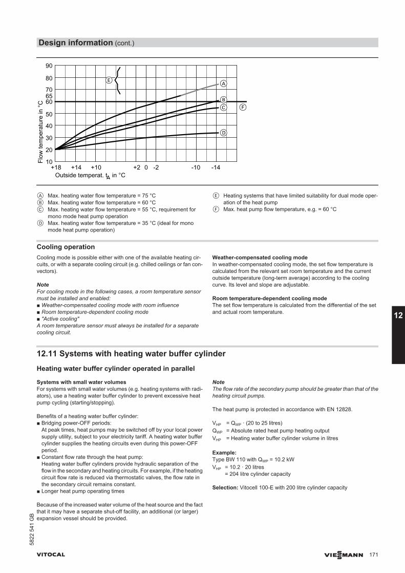
Outside temperat. tA in °C+14 +10 +2 0 -2 -10 -14
Flow
tem
pera
ture
in °
C
10
20
30
40
50
60
70
80
90
65
F
E
+18
D
CB
A
A Max. heating water flow temperature = 75 °CB Max. heating water flow temperature = 60 °CC Max. heating water flow temperature = 55 °C, requirement for
mono mode heat pump operationD Max. heating water flow temperature = 35 °C (ideal for mono
mode heat pump operation)
E Heating systems that have limited suitability for dual mode oper-ation of the heat pump
F Max. heat pump flow temperature, e.g. = 60 °C
Cooling operationCooling mode is possible either with one of the available heating cir-cuits, or with a separate cooling circuit (e.g. chilled ceilings or fan con-vectors).
NoteFor cooling mode in the following cases, a room temperature sensormust be installed and enabled:■ Weather-compensated cooling mode with room influence■ Room temperature-dependent cooling mode■ "Active cooling"A room temperature sensor must always be installed for a separatecooling circuit.
Weather-compensated cooling modeIn weather-compensated cooling mode, the set flow temperature iscalculated from the relevant set room temperature and the currentoutside temperature (long-term average) according to the coolingcurve. Its level and slope are adjustable.
Room temperature-dependent cooling modeThe set flow temperature is calculated from the differential of the setand actual room temperature.
12.11 Systems with heating water buffer cylinder
Heating water buffer cylinder operated in parallel
Systems with small water volumesFor systems with small water volumes (e.g. heating systems with radi-ators), use a heating water buffer cylinder to prevent excessive heatpump cycling (starting/stopping).
Benefits of a heating water buffer cylinder:■ Bridging power-OFF periods:
At peak times, heat pumps may be switched off by your local powersupply utility, subject to your electricity tariff. A heating water buffercylinder supplies the heating circuits even during this power-OFFperiod.
■ Constant flow rate through the heat pump:Heating water buffer cylinders provide hydraulic separation of theflow in the secondary and heating circuits. For example, if the heatingcircuit flow rate is reduced via thermostatic valves, the flow rate inthe secondary circuit remains constant.
■ Longer heat pump operating times
Because of the increased water volume of the heat source and the factthat it may have a separate shut-off facility, an additional (or larger)expansion vessel should be provided.
NoteThe flow rate of the secondary pump should be greater than that of theheating circuit pumps.
The heat pump is protected in accordance with EN 12828.
VHP = QWP · (20 to 25 litres)QWP = Absolute rated heat pump heating outputVHP = Heating water buffer cylinder volume in litres
Example:Type BW 110 with QWP = 10.2 kWVHP = 10.2 · 20 litres
= 204 litre cylinder capacity
Selection: Vitocell 100-E with 200 litre cylinder capacity
Design information (cont.)
VITOCAL VIESMANN 171
5822
541
GB
12
Heating water buffer cylinder for optimised runtimes
NoteWith two-stage heat pumps and heat pump cascades, the volume ofthe heating water buffer cylinder can be sized for runtime optimisationto match the heat pump with the highest rated heating output.
Heating water buffer cylinder for bridging periods when the supply is blockedThese versions are offered for heat distribution systems without addi-tional cylinder mass (e.g. radiators, hot water air heaters).Storing 100 % of heating energy for the duration of the power-OFFperiods is feasible, but not recommended, otherwise the cylinder vol-ume required would be too great.
Example:ΦHL = 10 kW = 10,000 WtSz = 2 h (max. 3 x per day)Δϑ = 10 KcP = 1.163 Wh/(kgK) for watercP spec. thermal capacity in kWh/(kg·K)ΦHL Heat load of the building in kWtSz Blocking time in hVHP Heating water buffer cylinder volume in lΔϑ System cool-down in K
100 % sizing(subject to the existing heating surfaces)
VHP =tSZHLΦ ·
ΔPc ·
VHP10000 W · 2 h
Whkg · k · 10 k1.163
=1720 kg=
1720 kg water represent a cylinder capacity of 1720 l.Selection: 2 Vitocell 100-E, each with 1000 litre cylinder capacity
Rough sizing(subject to the utilisation of the delayed building heat loss)VHP = ΦHL · (60 to 80 l)VHP = 10 · 60 lVHP = 600 l cylinder capacitySelection: 1 Vitocell 100-E with 750 l cylinder capacity
12.12 Water quality and heat transfer medium
DHWThe appliances can be used with potable water up to 20 °dH(3.58 mol/m3). In case of higher hardness levels, a softening systemfor potable water is required on site to protect the integral plate heatexchanger.
Heating water
Unsuitable fill and top-up water increases the level of deposits andcorrosion. This can lead to system damage.Observe VDI 2035 regarding quality and amount of heating water,including fill and top-up water.
■ Flush the heating system thoroughly before filling.■ Only fill with water of potable quality.■ Soften fill water with a water hardness above 16.8 °dH (3.0 mol/m3),
e.g. with the small softening system for heating water (see theVitoset pricelist).
Heat transfer medium, solar circuit (not for Vitocal 222-G, 333-G)■ Fill the solar circuit only with Tyfocor LS heat transfer medium (frost
protection down to −28 °C). Never dilute the heat transfer mediumwith water.
■ Provide an expansion vessel for the solar circuit, sized in accordancewith the details on page 187.
■ Never use zinc-plated/galvanised pipes or components for the solarcircuit.
Heat transfer medium, primary circuit (brine circuit)■ Fill the primary circuit exclusively with Tyfocor heat transfer medium
(frost protection down to −19 °C). Never dilute the heat transfermedium with water.
■ Provide an expansion vessel for the primary circuit, sized in accord-ance with the details on page 187.
■ Never use zinc-plated/galvanised pipes for the primary circuit.
Design information (cont.)
172 VIESMANN VITOCAL
12
5822
541
GB
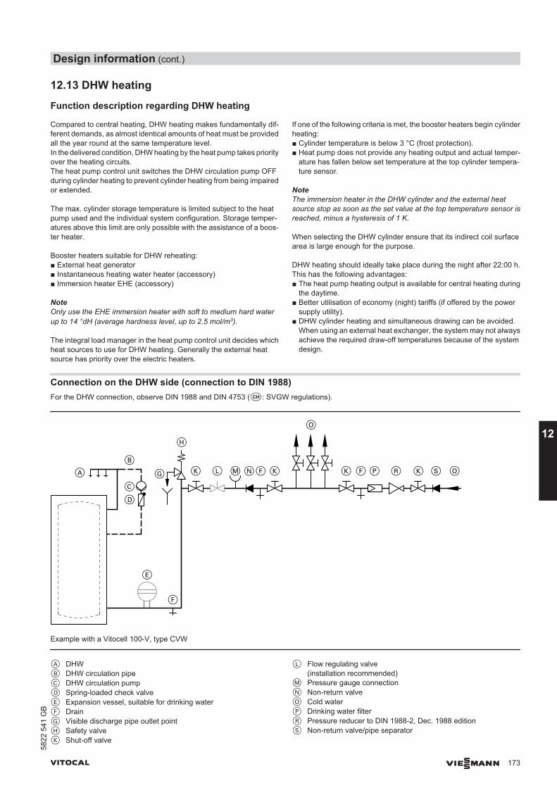
12.13 DHW heating
Function description regarding DHW heating
Compared to central heating, DHW heating makes fundamentally dif-ferent demands, as almost identical amounts of heat must be providedall the year round at the same temperature level.In the delivered condition, DHW heating by the heat pump takes priorityover the heating circuits.The heat pump control unit switches the DHW circulation pump OFFduring cylinder heating to prevent cylinder heating from being impairedor extended.
The max. cylinder storage temperature is limited subject to the heatpump used and the individual system configuration. Storage temper-atures above this limit are only possible with the assistance of a boos-ter heater.
Booster heaters suitable for DHW reheating:■ External heat generator■ Instantaneous heating water heater (accessory)■ Immersion heater EHE (accessory)
NoteOnly use the EHE immersion heater with soft to medium hard waterup to 14 °dH (average hardness level, up to 2.5 mol/m3).
The integral load manager in the heat pump control unit decides whichheat sources to use for DHW heating. Generally the external heatsource has priority over the electric heaters.
If one of the following criteria is met, the booster heaters begin cylinderheating:■ Cylinder temperature is below 3 °C (frost protection).■ Heat pump does not provide any heating output and actual temper-
ature has fallen below set temperature at the top cylinder tempera-ture sensor.
NoteThe immersion heater in the DHW cylinder and the external heatsource stop as soon as the set value at the top temperature sensor isreached, minus a hysteresis of 1 K.
When selecting the DHW cylinder ensure that its indirect coil surfacearea is large enough for the purpose.
DHW heating should ideally take place during the night after 22:00 h.This has the following advantages:■ The heat pump heating output is available for central heating during
the daytime.■ Better utilisation of economy (night) tariffs (if offered by the power
supply utility).■ DHW cylinder heating and simultaneous drawing can be avoided.
When using an external heat exchanger, the system may not alwaysachieve the required draw-off temperatures because of the systemdesign.
Connection on the DHW side (connection to DIN 1988)For the DHW connection, observe DIN 1988 and DIN 4753 (c: SVGW regulations).
KKA
B
C
D
G
H
L M NF
O
K F P R K S O
F
E
Example with a Vitocell 100-V, type CVW
A DHWB DHW circulation pipeC DHW circulation pumpD Spring-loaded check valveE Expansion vessel, suitable for drinking waterF DrainG Visible discharge pipe outlet pointH Safety valveK Shut-off valve
L Flow regulating valve(installation recommended)
M Pressure gauge connectionN Non-return valveO Cold waterP Drinking water filterR Pressure reducer to DIN 1988-2, Dec. 1988 editionS Non-return valve/pipe separator
Design information (cont.)
VITOCAL VIESMANN 173
5822
541
GB
12
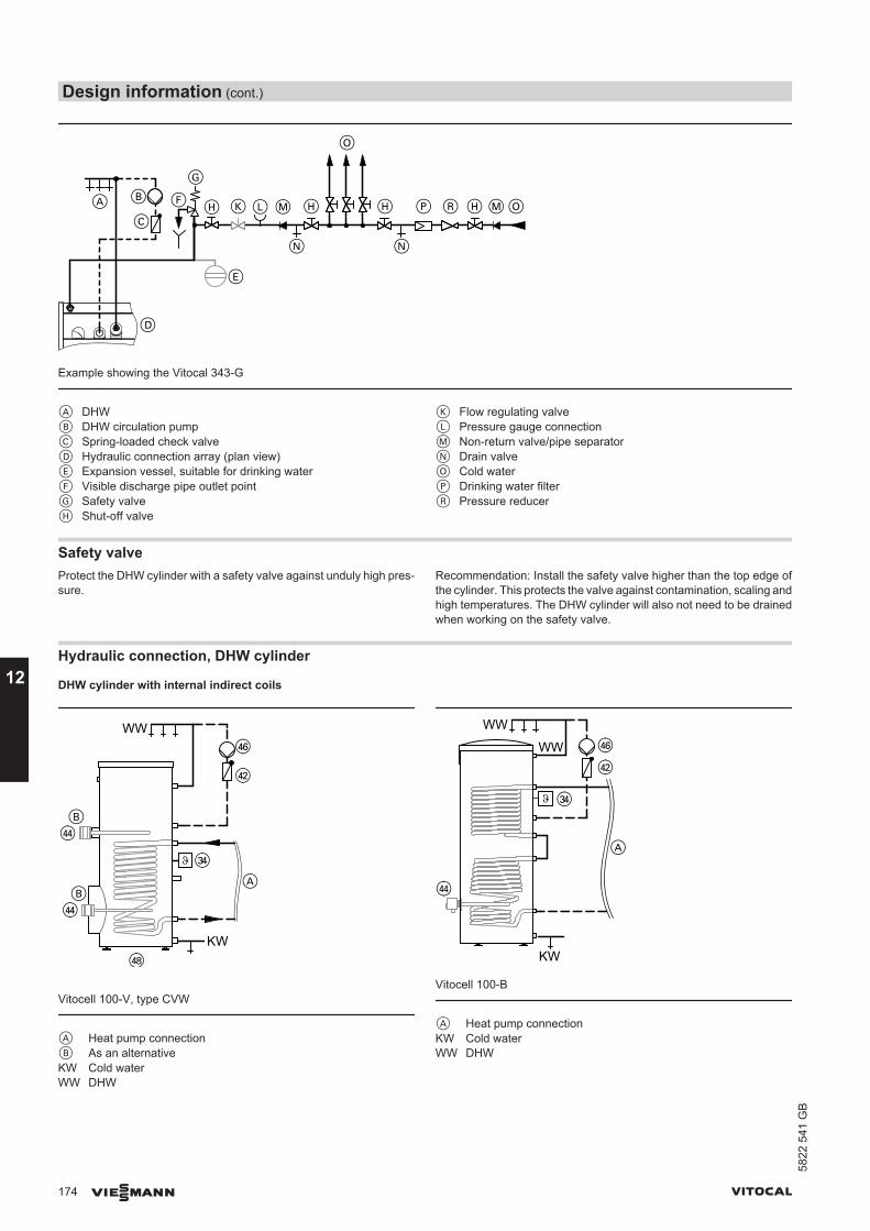
MA
N
B
CLK
D
H
O
N
H P R H MOH
G
F
E
Example showing the Vitocal 343-G
A DHWB DHW circulation pumpC Spring-loaded check valveD Hydraulic connection array (plan view)E Expansion vessel, suitable for drinking waterF Visible discharge pipe outlet pointG Safety valveH Shut-off valve
K Flow regulating valveL Pressure gauge connectionM Non-return valve/pipe separatorN Drain valveO Cold waterP Drinking water filterR Pressure reducer
Safety valveProtect the DHW cylinder with a safety valve against unduly high pres-sure.
Recommendation: Install the safety valve higher than the top edge ofthe cylinder. This protects the valve against contamination, scaling andhigh temperatures. The DHW cylinder will also not need to be drainedwhen working on the safety valve.
Hydraulic connection, DHW cylinder
DHW cylinder with internal indirect coils
WW
KW
Vitocell 100-V, type CVW
A Heat pump connectionB As an alternativeKW Cold waterWW DHW
WW
KW
A
WW
rR
eR
rZ
rW
Vitocell 100-B
A Heat pump connectionKW Cold waterWW DHW
Design information (cont.)
174 VIESMANN VITOCAL
12
5822
541
GB
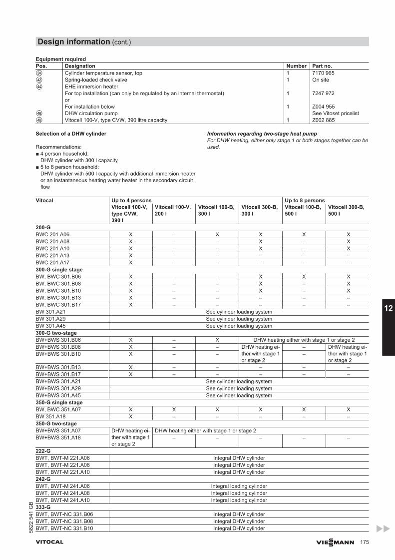
Equipment requiredPos. Designation Number Part no.eR Cylinder temperature sensor, top 1 7170 965rW Spring-loaded check valve 1 On siterR EHE immersion heater For top installation (can only be regulated by an internal thermostat)
or1 7247 972
For installation below 1 Z004 955rZ DHW circulation pump See Vitoset pricelistrI Vitocell 100-V, type CVW, 390 litre capacity 1 Z002 885
Selection of a DHW cylinder
Recommendations:■ 4 person household:
DHW cylinder with 300 l capacity■ 5 to 8 person household:
DHW cylinder with 500 l capacity with additional immersion heateror an instantaneous heating water heater in the secondary circuitflow
Information regarding two-stage heat pumpFor DHW heating, either only stage 1 or both stages together can beused.
Vitocal Up to 4 persons Up to 8 personsVitocell 100-V,type CVW,390 l
Vitocell 100-V,200 l
Vitocell 100-B,300 l
Vitocell 300-B,300 l
Vitocell 100-B,500 l
Vitocell 300-B,500 l
200-GBWC 201.A06 X – X X X XBWC 201.A08 X – – X – XBWC 201.A10 X – – X – XBWC 201.A13 X – – – – –BWC 201.A17 X – – – – –300-G single stageBW, BWC 301.B06 X – – X X XBW, BWC 301.B08 X – – X – XBW, BWC 301.B10 X – – X – XBW, BWC 301.B13 X – – – – –BW, BWC 301.B17 X – – – – –BW 301.A21 See cylinder loading systemBW 301.A29 See cylinder loading systemBW 301.A45 See cylinder loading system300-G two-stageBW+BWS 301.B06 X – X DHW heating either with stage 1 or stage 2BW+BWS 301.B08 X – – DHW heating ei-
ther with stage 1or stage 2
– DHW heating ei-ther with stage 1or stage 2
BW+BWS 301.B10 X – – –
BW+BWS 301.B13 X – – – – –BW+BWS 301.B17 X – – – – –BW+BWS 301.A21 See cylinder loading systemBW+BWS 301.A29 See cylinder loading systemBW+BWS 301.A45 See cylinder loading system350-G single stageBW, BWC 351.A07 X X X X X XBW 351.A18 X – – – – –350-G two-stageBW+BWS 351.A07 DHW heating ei-
ther with stage 1or stage 2
DHW heating either with stage 1 or stage 2BW+BWS 351.A18 – – – – –
222-GBWT, BWT-M 221.A06 Integral DHW cylinderBWT, BWT-M 221.A08 Integral DHW cylinderBWT, BWT-M 221.A10 Integral DHW cylinder242-GBWT, BWT-M 241.A06 Integral loading cylinderBWT, BWT-M 241.A08 Integral loading cylinderBWT, BWT-M 241.A10 Integral loading cylinder333-GBWT, BWT-NC 331.B06 Integral DHW cylinderBWT, BWT-NC 331.B08 Integral DHW cylinderBWT, BWT-NC 331.B10 Integral DHW cylinder
Design information (cont.)
VITOCAL VIESMANN 175
5822
541
GB
12
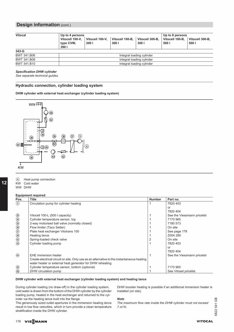
Vitocal Up to 4 persons Up to 8 personsVitocell 100-V,type CVW,390 l
Vitocell 100-V,200 l
Vitocell 100-B,300 l
Vitocell 300-B,300 l
Vitocell 100-B,500 l
Vitocell 300-B,500 l
343-GBWT 341.B06 Integral loading cylinderBWT 341.B08 Integral loading cylinderBWT 341.B10 Integral loading cylinder
Specification DHW cylinderSee separate technical guides.
Hydraulic connection, cylinder loading system
DHW cylinder with external heat exchanger (cylinder loading system)
eI
KW
rZ
A
WW
M
5
rW
eR eT eZ eU
rR
eP
rT
rE rW
A Heat pump connectionKW Cold waterWW DHW
Equipment requiredPos. Title Number Part no.5 Circulation pump for cylinder heating 1 7820 403
or7820 404
eP Vitocell 100-L (500 l capacity) 1 See the Viessmann pricelisteR Cylinder temperature sensor, top 1 7170 965eT 2-way motorised ball valve (normally closed) 1 7180 573eZ Flow limiter (Taco Setter) 1 On siteeU Plate heat exchanger Vitotrans 100 1 See page 178eI Heating lance 1 Z004 280rW Spring-loaded check valve 2 On siterE Cylinder loading pump 1 7820 403
or7820 404
rR EHE immersion heaterCreate electrical circuit on site. Only use as an alternative to the instantaneous heatingwater heater or external heat generator for DHW reheating.
1 See the Viessmann pricelist
rT Cylinder temperature sensor, bottom (optional) 1 7170 965rZ DHW circulation pump 1 See Vitoset pricelist
DHW cylinder with external heat exchanger (cylinder loading system) and heating lance
During cylinder loading (no draw-off) in the cylinder loading system,cold water is drawn from the bottom of the DHW cylinder by the cylinderloading pump, heated in the heat exchanger and returned to the cyl-inder via the heating lance built into the flange.The generously sized outlet apertures in the immersion heating lanceresult in low flow velocities, which in turn provide a clean temperaturestratification inside the DHW cylinder.
DHW booster heating is possible if an additional immersion heater isinstalled (on site).
NoteThe maximum flow rate inside the DHW cylinder must not exceed7 m3/h.
Design information (cont.)
176 VIESMANN VITOCAL
12
5822
541
GB
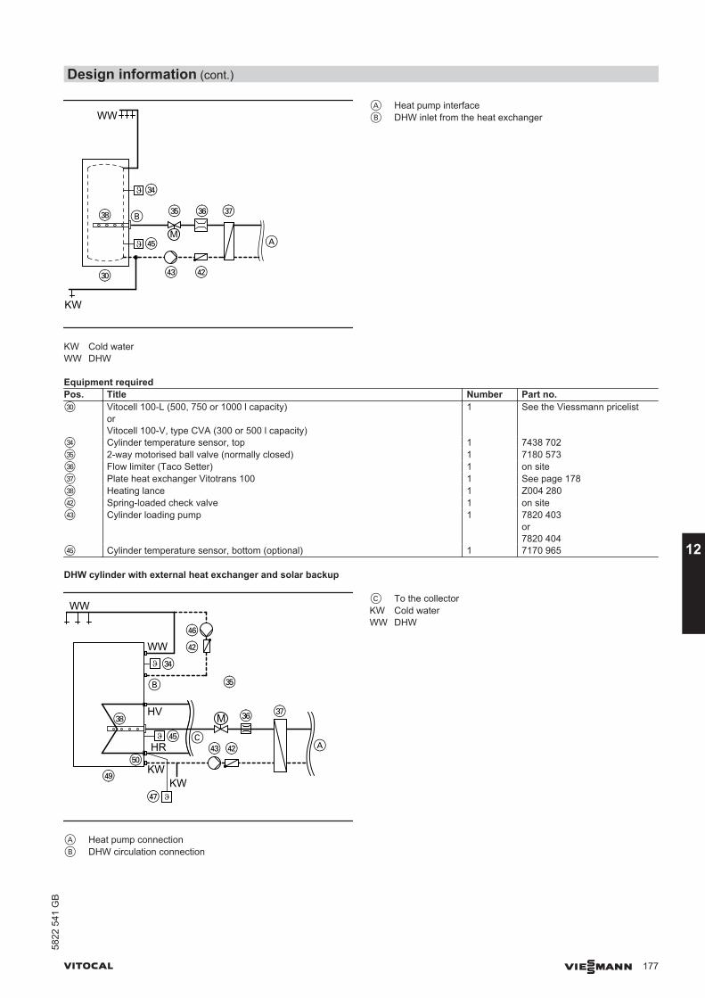
KW
A
WW
M
B eT eZ eUeI
rT
eP rE rW
eR
KW Cold waterWW DHW
A Heat pump interfaceB DHW inlet from the heat exchanger
Equipment requiredPos. Title Number Part no.eP Vitocell 100-L (500, 750 or 1000 l capacity)
orVitocell 100-V, type CVA (300 or 500 l capacity)
1 See the Viessmann pricelist
eR Cylinder temperature sensor, top 1 7438 702eT 2-way motorised ball valve (normally closed) 1 7180 573eZ Flow limiter (Taco Setter) 1 on siteeU Plate heat exchanger Vitotrans 100 1 See page 178eI Heating lance 1 Z004 280rW Spring-loaded check valve 1 on siterE Cylinder loading pump 1 7820 403
or7820 404
rT Cylinder temperature sensor, bottom (optional) 1 7170 965
DHW cylinder with external heat exchanger and solar backup
tP
eI
rE rW
eZ
rO
A
eR
eT
rZ
rU
rW
C
B
eU
HR
WW
WW
KW
MHV
KW
rT
A Heat pump connectionB DHW circulation connection
C To the collectorKW Cold waterWW DHW
Design information (cont.)
VITOCAL VIESMANN 177
5822
541
GB
12
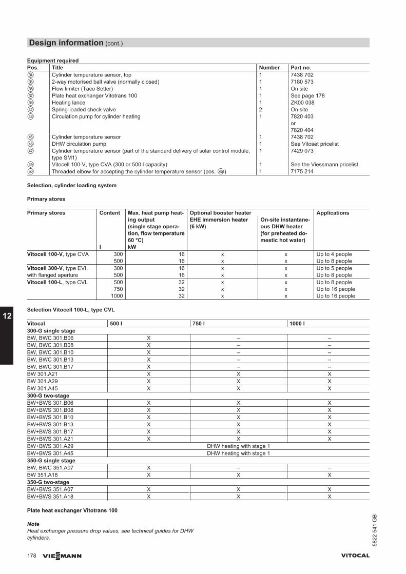
Equipment requiredPos. Title Number Part no.eR Cylinder temperature sensor, top 1 7438 702eT 2-way motorised ball valve (normally closed) 1 7180 573eZ Flow limiter (Taco Setter) 1 On siteeU Plate heat exchanger Vitotrans 100 1 See page 178eI Heating lance 1 ZK00 038rW Spring-loaded check valve 2 On siterE Circulation pump for cylinder heating 1 7820 403
or7820 404
rT Cylinder temperature sensor 1 7438 702rZ DHW circulation pump 1 See Vitoset pricelistrU Cylinder temperature sensor (part of the standard delivery of solar control module,
type SM1)1 7429 073
rO Vitocell 100-V, type CVA (300 or 500 l capacity) 1 See the Viessmann pricelisttP Threaded elbow for accepting the cylinder temperature sensor (pos. rT) 1 7175 214
Selection, cylinder loading system
Primary stores
Primary stores Content Max. heat pump heat-ing output(single stage opera-tion, flow temperature60 °C)
Optional booster heater ApplicationsEHE immersion heater(6 kW)
On-site instantane-ous DHW heater(for preheated do-mestic hot water)
l kWVitocell 100-V, type CVA 300 16 x x Up to 4 people 500 16 x x Up to 8 peopleVitocell 300-V, type EVI, 300 16 x x Up to 5 peoplewith flanged aperture 500 16 x x Up to 8 peopleVitocell 100-L, type CVL 500 32 x x Up to 8 people
750 32 x x Up to 16 people1000 32 x x Up to 16 people
Selection Vitocell 100-L, type CVL
Vitocal 500 l 750 l 1000 l300-G single stageBW, BWC 301.B06 X – –BW, BWC 301.B08 X – –BW, BWC 301.B10 X – –BW, BWC 301.B13 X – –BW, BWC 301.B17 X – –BW 301.A21 X X XBW 301.A29 X X XBW 301.A45 X X X300-G two-stageBW+BWS 301.B06 X X XBW+BWS 301.B08 X X XBW+BWS 301.B10 X X XBW+BWS 301.B13 X X XBW+BWS 301.B17 X X XBW+BWS 301.A21 X X XBW+BWS 301.A29 DHW heating with stage 1BW+BWS 301.A45 DHW heating with stage 1350-G single stageBW, BWC 351.A07 X – –BW 351.A18 X X X350-G two-stageBW+BWS 351.A07 X X XBW+BWS 351.A18 X X X
Plate heat exchanger Vitotrans 100
NoteHeat exchanger pressure drop values, see technical guides for DHWcylinders.
Design information (cont.)
178 VIESMANN VITOCAL
12
5822
541
GB
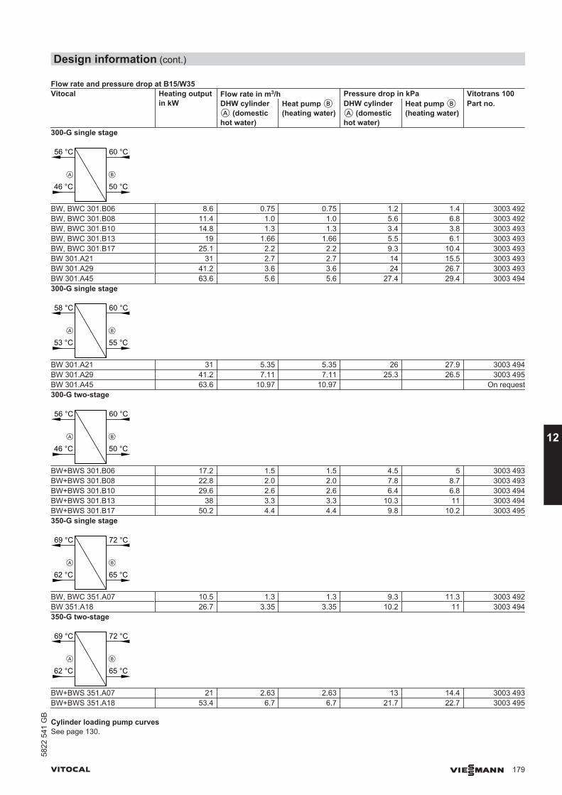
Flow rate and pressure drop at B15/W35Vitocal Heating output
in kWFlow rate in m3/h Pressure drop in kPa Vitotrans 100DHW cylinderA (domestichot water)
Heat pump B(heating water)
DHW cylinderA (domestichot water)
Heat pump B(heating water)
Part no.
300-G single stage
60 °C
46 °C 50 °C
56 °C
A B
BW, BWC 301.B06 8.6 0.75 0.75 1.2 1.4 3003 492BW, BWC 301.B08 11.4 1.0 1.0 5.6 6.8 3003 492BW, BWC 301.B10 14.8 1.3 1.3 3.4 3.8 3003 493BW, BWC 301.B13 19 1.66 1.66 5.5 6.1 3003 493BW, BWC 301.B17 25.1 2.2 2.2 9.3 10.4 3003 493BW 301.A21 31 2.7 2.7 14 15.5 3003 493BW 301.A29 41.2 3.6 3.6 24 26.7 3003 493BW 301.A45 63.6 5.6 5.6 27.4 29.4 3003 494300-G single stage
60 °C
53 °C 55 °C
58 °C
A B
BW 301.A21 31 5.35 5.35 26 27.9 3003 494BW 301.A29 41.2 7.11 7.11 25.3 26.5 3003 495BW 301.A45 63.6 10.97 10.97 On request300-G two-stage
60 °C
46 °C 50 °C
56 °C
A B
BW+BWS 301.B06 17.2 1.5 1.5 4.5 5 3003 493BW+BWS 301.B08 22.8 2.0 2.0 7.8 8.7 3003 493BW+BWS 301.B10 29.6 2.6 2.6 6.4 6.8 3003 494BW+BWS 301.B13 38 3.3 3.3 10.3 11 3003 494BW+BWS 301.B17 50.2 4.4 4.4 9.8 10.2 3003 495350-G single stage
72 °C
62 °C 65 °C
69 °C
A B
BW, BWC 351.A07 10.5 1.3 1.3 9.3 11.3 3003 492BW 351.A18 26.7 3.35 3.35 10.2 11 3003 494350-G two-stage
72 °C
62 °C 65 °C
69 °C
A B
BW+BWS 351.A07 21 2.63 2.63 13 14.4 3003 493BW+BWS 351.A18 53.4 6.7 6.7 21.7 22.7 3003 495
Cylinder loading pump curvesSee page 130.
Design information (cont.)
VITOCAL VIESMANN 179
5822
541
GB
12
12.14 Cooling mode
Types and configuration
Subject to system version the following cooling functions are possible:■ "Natural cooling" (as option with or without mixer)
– The compressor is shut down and heat exchange occurs directlywith the primary circuit.
■ "Active cooling"– The heat pump is used as a refrigeration unit, meaning a higher
cooling capacity is possible than with natural cooling.– This function is only possible outside a power-OFF period, and
must be enabled separately by the system user.
Even if active cooling is selected and enabled, the control unit will ini-tially start the natural cooling function. If the set room temperaturecannot be achieved with this function for a prolonged period, the com-pressor starts.A mixer can only be used with natural cooling, and particularly in cool-ing mode on underfloor heating circuits, it keeps the flow temperatureabove the dew point. To ensure the transfer of the high cooling outputin active cooling at all times, no mixer is provided.
Cooling function "Natural cooling"
Function description
With natural cooling, the heat pump control unit regulates the followingfunctions:■ Switching all necessary circulation pumps, diverter valves and mix-
ers■ Recording all essential temperatures■ Dew point monitoring
The control unit enables the natural cooling function if the outside tem-perature exceeds the cooling limit (adjustable). Control operated inweather-compensated mode when cooling via heating circuit (under-floor heating circuit). When a separate cooling circuit is used, e.g. afan convector, then the control is room temperature-dependent.DHW heating by the heat pump is possible during the cooling opera-tion.
Note■ For cooling operation via a separate cooling circuit, a room temper-
ature sensor must be installed and enabled.■ For cooling operation via a separate cooling circuit or heating circuit
without mixer, use a contact temperature sensor to capture the flowtemperature.
NC-Box■ The installation room must be dry and free from the risk of frost.■ Vitocal 200-G/300-G: Install the NC-Box inside the installation room
above the heat pump and connect with the corrugated pipes sup-plied.
■ Compact heat pumps: Install the NC-Box near the compact heatpump and use on-site pipes for the hydraulic connection.
■ Carry out the diffusion-proof thermal insulation of all brine and coldwater lines in accordance with standard practice to prevent conden-sation.
■ Power supply (1/N/PE, 230 V/50 Hz) is required.Recommendation: Utilise the heat pump power supply from an on-site power distribution board.
■ If the NC-Box is used with a separate cooling circuit (exclusivelyused for cooling), protect that circuit via an additional expansionvessel and safety valve.
■ Use only Teflon and EPDM seals for the connections on the NC-Box.
Natural cooling with the NC-BoxSubject to the probe/collector system and the temperatures underground, the NC-Box can transfer a cooling capacity of up to 5 kW.For cooling, it is possible to connect either a heating/cooling circuit,e.g. underfloor heating circuit or a separate cooling circuit, e.g. a fanconvector.
The NC-Box is supplied with all necessary components:■ Circulation pumps■ Diverter valves■ Mixer■ Sensors■ KM BUS interface for heat pump control unit
The heat that is extracted from the heating/cooling circuit is transferredto the ground by the heat exchanger in the NC-Box. This heatexchanger is connected in series and enables a system separationbetween the primary and the heating circuit.
NoteThermally insulate all lines on site with vapour diffusion-proof mate-rial.
Arrangement of the NC-Box adjacent to the heat pump■ For compact heat pumps Vitocal 222-G, 242-G, 333-G type BWT,
343-G■ For Vitocal 200-G, 300-G, if there is insufficient space above the heat
pump to carry out the installation.■ Hydraulic connection with on-site pipework.
Arrangement of the NC-Box above the heat pump■ For Vitocal 200-G, 300-G type 301.B06 to B17■ Hydraulic connection with corrugated pipe set
Design information (cont.)
180 VIESMANN VITOCAL
12
5822
541
GB
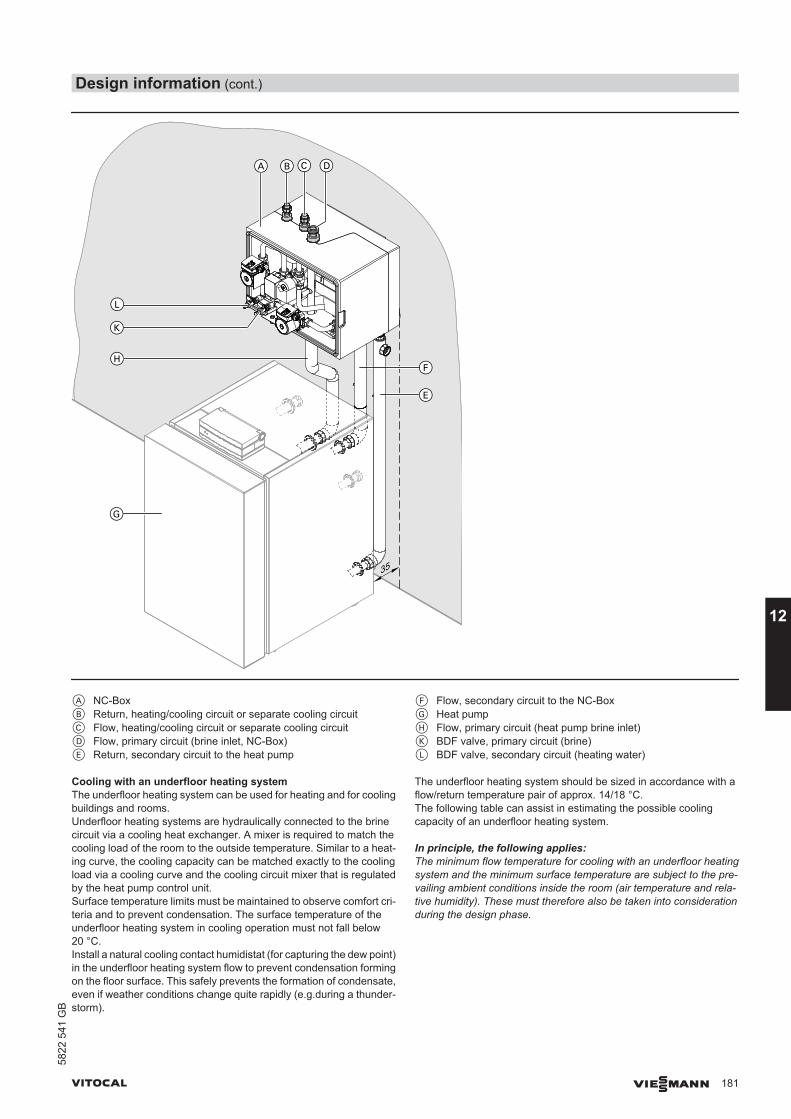
35
BC D
E
F
L
K
H
A
G
A NC-BoxB Return, heating/cooling circuit or separate cooling circuitC Flow, heating/cooling circuit or separate cooling circuitD Flow, primary circuit (brine inlet, NC-Box)E Return, secondary circuit to the heat pump
F Flow, secondary circuit to the NC-BoxG Heat pumpH Flow, primary circuit (heat pump brine inlet)K BDF valve, primary circuit (brine)L BDF valve, secondary circuit (heating water)
Cooling with an underfloor heating systemThe underfloor heating system can be used for heating and for coolingbuildings and rooms.Underfloor heating systems are hydraulically connected to the brinecircuit via a cooling heat exchanger. A mixer is required to match thecooling load of the room to the outside temperature. Similar to a heat-ing curve, the cooling capacity can be matched exactly to the coolingload via a cooling curve and the cooling circuit mixer that is regulatedby the heat pump control unit.Surface temperature limits must be maintained to observe comfort cri-teria and to prevent condensation. The surface temperature of theunderfloor heating system in cooling operation must not fall below20 °C.Install a natural cooling contact humidistat (for capturing the dew point)in the underfloor heating system flow to prevent condensation formingon the floor surface. This safely prevents the formation of condensate,even if weather conditions change quite rapidly (e.g.during a thunder-storm).
The underfloor heating system should be sized in accordance with aflow/return temperature pair of approx. 14/18 °C.The following table can assist in estimating the possible coolingcapacity of an underfloor heating system.
In principle, the following applies:The minimum flow temperature for cooling with an underfloor heatingsystem and the minimum surface temperature are subject to the pre-vailing ambient conditions inside the room (air temperature and rela-tive humidity). These must therefore also be taken into considerationduring the design phase.
Design information (cont.)
VITOCAL VIESMANN 181
5822
541
GB
12
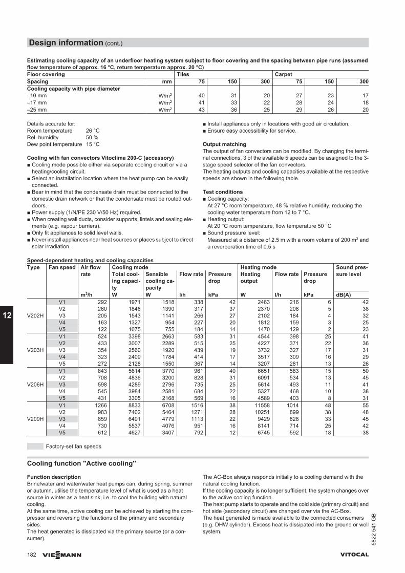
Estimating cooling capacity of an underfloor heating system subject to floor covering and the spacing between pipe runs (assumedflow temperature of approx. 16 °C, return temperature approx. 20 °C)Floor covering Tiles CarpetSpacing mm 75 150 300 75 150 300Cooling capacity with pipe diameter –10 mm W/m2 40 31 20 27 23 17–17 mm W/m2 41 33 22 28 24 18–25 mm W/m2 43 36 25 29 26 20
Details accurate for:Room temperature 26 °CRel. humidity 50 %Dew point temperature 15 °C
Cooling with fan convectors Vitoclima 200-C (accessory)■ Cooling mode possible either via separate cooling circuit or via a
heating/cooling circuit.■ Select an installation location where the heat pump can be easily
connected.■ Bear in mind that the condensate drain must be connected to the
domestic drain network or that the condensate must be routed out-doors.
■ Power supply (1/N/PE 230 V/50 Hz) required.■ When creating wall ducts, consider supports, lintels and sealing ele-
ments (e.g. vapour barriers).■ Only fit appliances to solid level walls.■ Never install appliances near heat sources or places subject to direct
solar irradiation.
■ Install appliances only in locations with good air circulation.■ Ensure easy accessibility for service.
Output matchingThe output of fan convectors can be modified. By changing the termi-nal connections, 3 of the available 5 speeds can be assigned to the 3-stage speed selector of the fan convectors.The heating outputs and cooling capacities available at the respectivespeeds are shown in the following table.
Test conditions■ Cooling capacity:
At 27 °C room temperature, 48 % relative humidity, reducing thecooling water temperature from 12 to 7 °C.
■ Heating output:At 20 °C room temperature, flow temperature 50 °C
■ Sound pressure level:Measured at a distance of 2.5 m with a room volume of 200 m3 anda reverberation time of 0.5 s
Speed-dependent heating and cooling capacitiesType Fan speed Air flow
rateCooling mode Heating mode Sound pres-
sure levelTotal cool-ing capaci-ty
Sensiblecooling ca-pacity
Flow rate Pressuredrop
Heatingoutput
Flow rate Pressuredrop
m3/h W W l/h kPa W l/h kPa dB(A)
V202H
V1 292 1971 1518 338 42 2463 216 6 42V2 260 1846 1390 317 37 2370 208 5 38V3 205 1543 1141 266 27 2102 184 4 32V4 163 1327 954 227 20 1812 159 3 25V5 122 1075 755 184 14 1470 129 2 23
V203H
V1 524 3398 2663 583 31 4544 398 25 41V2 433 3007 2289 515 25 4227 371 22 36V3 354 2560 1920 439 19 3732 327 17 31V4 323 2409 1784 414 17 3517 309 16 29V5 272 2128 1550 367 14 3207 281 13 26
V206H
V1 843 5614 3770 961 40 6651 583 15 50V2 708 4836 3200 828 31 6091 534 13 45V3 598 4289 2796 735 25 5614 493 11 41V4 545 3984 2581 684 22 5327 468 10 38V5 431 3305 2168 569 16 4589 403 8 31
V209H
V1 1266 8833 6708 1516 38 11558 1014 48 55V2 983 7402 5464 1271 28 10251 899 38 48V3 859 6491 4779 1113 22 9429 828 33 45V4 730 5537 4076 951 16 8141 714 25 42V5 612 4627 3407 792 12 6745 592 18 38
Factory-set fan speeds
Cooling function "Active cooling"
Function descriptionBrine/water and water/water heat pumps can, during spring, summeror autumn, utilise the temperature level of what is used as a heatsource in winter as a heat sink, i.e. to cool the building with naturalcooling.At the same time, active cooling can be achieved by starting the com-pressor and reversing the functions of the primary and secondarysides.The heat generated is dissipated via the primary source (or a con-sumer).
The AC-Box always responds initially to a cooling demand with thenatural cooling function.If the cooling capacity is no longer sufficient, the system changes overto the active cooling function.The heat pump starts to operate and the cold side (primary circuit) andhot side (secondary circuit) are changed over via the AC-Box.The heat generated is made available to the connected consumers(e.g. DHW cylinder). Excess heat is dissipated into the ground or wellsystem.
Design information (cont.)
182 VIESMANN VITOCAL
12
5822
541
GB
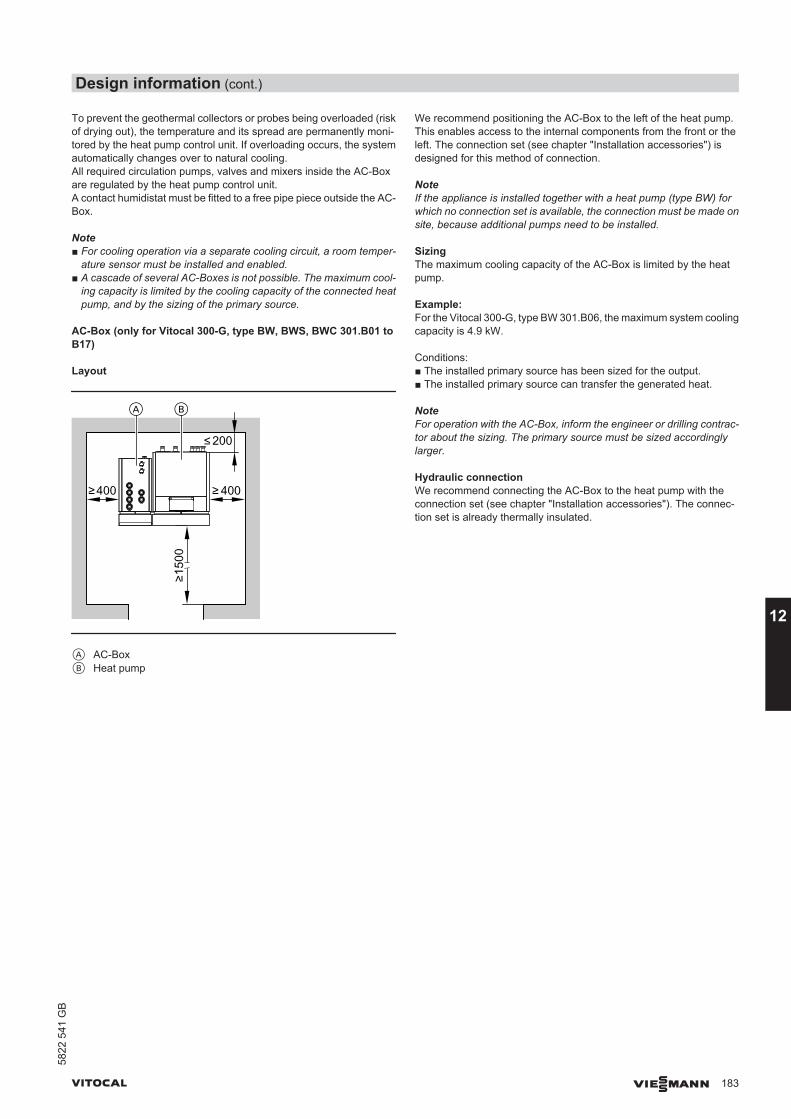
To prevent the geothermal collectors or probes being overloaded (riskof drying out), the temperature and its spread are permanently moni-tored by the heat pump control unit. If overloading occurs, the systemautomatically changes over to natural cooling.All required circulation pumps, valves and mixers inside the AC-Boxare regulated by the heat pump control unit. A contact humidistat must be fitted to a free pipe piece outside the AC-Box.
Note■ For cooling operation via a separate cooling circuit, a room temper-
ature sensor must be installed and enabled.■ A cascade of several AC-Boxes is not possible. The maximum cool-
ing capacity is limited by the cooling capacity of the connected heatpump, and by the sizing of the primary source.
AC-Box (only for Vitocal 300-G, type BW, BWS, BWC 301.B01 toB17)
Layout
A B
200
400400
1500
A AC-BoxB Heat pump
We recommend positioning the AC-Box to the left of the heat pump.This enables access to the internal components from the front or theleft. The connection set (see chapter "Installation accessories") isdesigned for this method of connection.
NoteIf the appliance is installed together with a heat pump (type BW) forwhich no connection set is available, the connection must be made onsite, because additional pumps need to be installed.
SizingThe maximum cooling capacity of the AC-Box is limited by the heatpump.
Example:For the Vitocal 300-G, type BW 301.B06, the maximum system coolingcapacity is 4.9 kW.
Conditions:■ The installed primary source has been sized for the output.■ The installed primary source can transfer the generated heat.
NoteFor operation with the AC-Box, inform the engineer or drilling contrac-tor about the sizing. The primary source must be sized accordinglylarger.
Hydraulic connectionWe recommend connecting the AC-Box to the heat pump with theconnection set (see chapter "Installation accessories"). The connec-tion set is already thermally insulated.
Design information (cont.)
VITOCAL VIESMANN 183
5822
541
GB
12
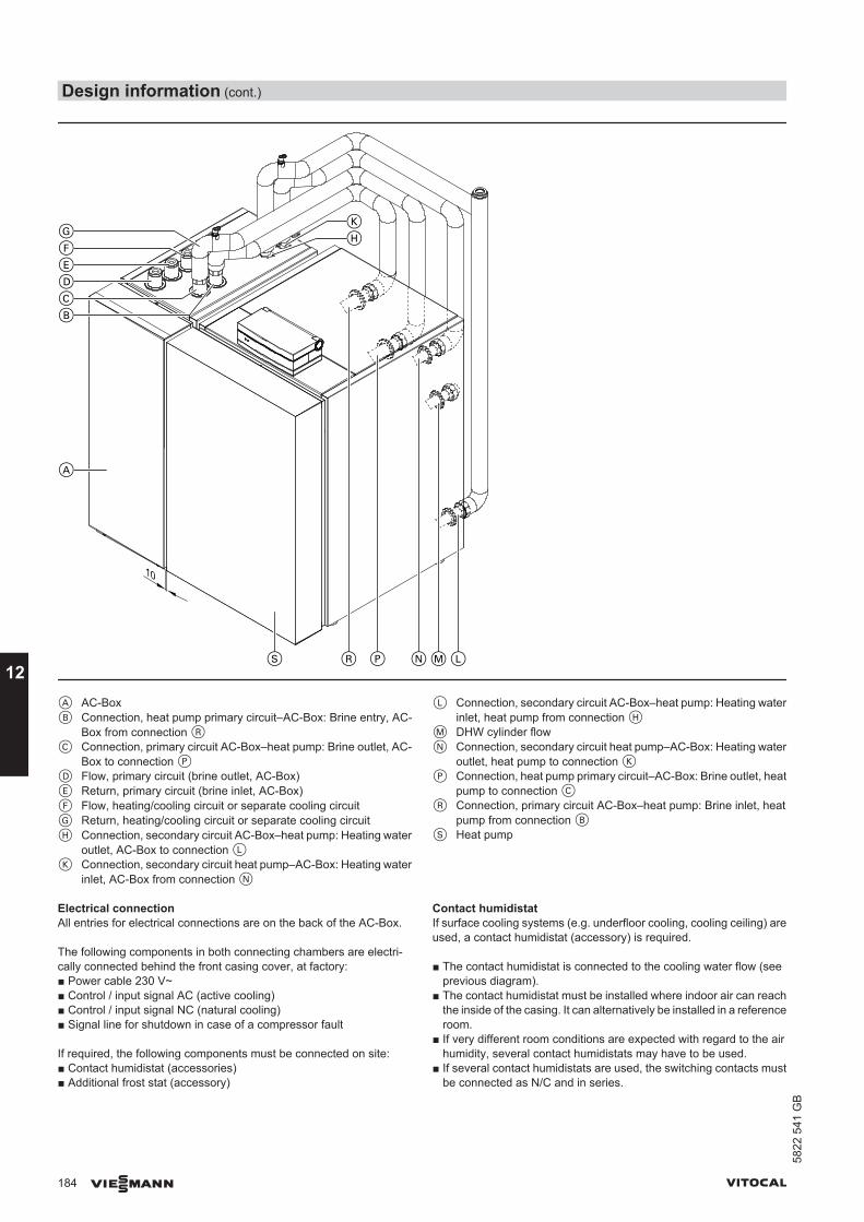
10
DEFG
CB
HK
A
S R P N LM
A AC-BoxB Connection, heat pump primary circuit–AC-Box: Brine entry, AC-
Box from connection RC Connection, primary circuit AC-Box–heat pump: Brine outlet, AC-
Box to connection PD Flow, primary circuit (brine outlet, AC-Box)E Return, primary circuit (brine inlet, AC-Box)F Flow, heating/cooling circuit or separate cooling circuitG Return, heating/cooling circuit or separate cooling circuitH Connection, secondary circuit AC-Box–heat pump: Heating water
outlet, AC-Box to connection LK Connection, secondary circuit heat pump–AC-Box: Heating water
inlet, AC-Box from connection N
L Connection, secondary circuit AC-Box–heat pump: Heating waterinlet, heat pump from connection H
M DHW cylinder flowN Connection, secondary circuit heat pump–AC-Box: Heating water
outlet, heat pump to connection KP Connection, heat pump primary circuit–AC-Box: Brine outlet, heat
pump to connection CR Connection, primary circuit AC-Box–heat pump: Brine inlet, heat
pump from connection BS Heat pump
Electrical connectionAll entries for electrical connections are on the back of the AC-Box.
The following components in both connecting chambers are electri-cally connected behind the front casing cover, at factory:■ Power cable 230 V~■ Control / input signal AC (active cooling)■ Control / input signal NC (natural cooling)■ Signal line for shutdown in case of a compressor fault
If required, the following components must be connected on site:■ Contact humidistat (accessories)■ Additional frost stat (accessory)
Contact humidistatIf surface cooling systems (e.g. underfloor cooling, cooling ceiling) areused, a contact humidistat (accessory) is required.
■ The contact humidistat is connected to the cooling water flow (seeprevious diagram).
■ The contact humidistat must be installed where indoor air can reachthe inside of the casing. It can alternatively be installed in a referenceroom.
■ If very different room conditions are expected with regard to the airhumidity, several contact humidistats may have to be used.
■ If several contact humidistats are used, the switching contacts mustbe connected as N/C and in series.
Design information (cont.)
184 VIESMANN VITOCAL
12
5822
541
GB
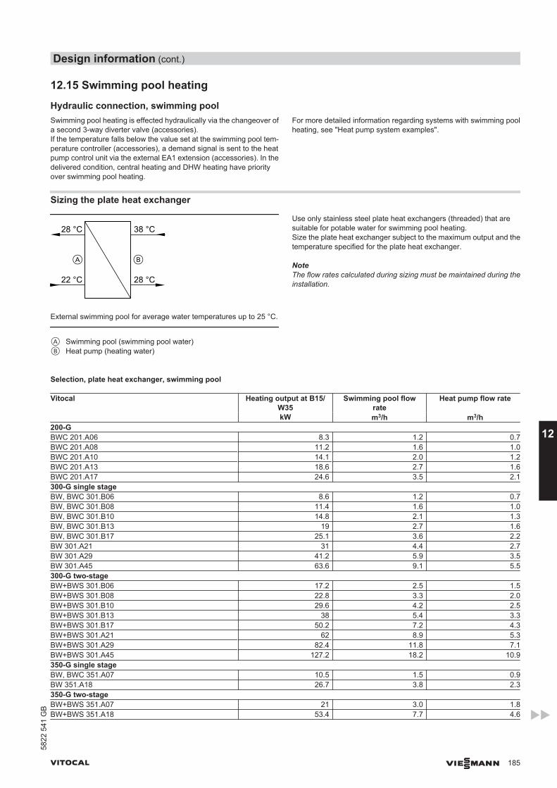
12.15 Swimming pool heating
Hydraulic connection, swimming poolSwimming pool heating is effected hydraulically via the changeover ofa second 3-way diverter valve (accessories).If the temperature falls below the value set at the swimming pool tem-perature controller (accessories), a demand signal is sent to the heatpump control unit via the external EA1 extension (accessories). In thedelivered condition, central heating and DHW heating have priorityover swimming pool heating.
For more detailed information regarding systems with swimming poolheating, see "Heat pump system examples".
Sizing the plate heat exchanger
38 °C
22 °C 28 °C
28 °C
External swimming pool for average water temperatures up to 25 °C.
A Swimming pool (swimming pool water)B Heat pump (heating water)
Use only stainless steel plate heat exchangers (threaded) that aresuitable for potable water for swimming pool heating.Size the plate heat exchanger subject to the maximum output and thetemperature specified for the plate heat exchanger.
NoteThe flow rates calculated during sizing must be maintained during theinstallation.
Selection, plate heat exchanger, swimming pool
Vitocal Heating output at B15/W35
Swimming pool flowrate
Heat pump flow rate
kW m3/h m3/h200-GBWC 201.A06 8.3 1.2 0.7BWC 201.A08 11.2 1.6 1.0BWC 201.A10 14.1 2.0 1.2BWC 201.A13 18.6 2.7 1.6BWC 201.A17 24.6 3.5 2.1300-G single stageBW, BWC 301.B06 8.6 1.2 0.7BW, BWC 301.B08 11.4 1.6 1.0BW, BWC 301.B10 14.8 2.1 1.3BW, BWC 301.B13 19 2.7 1.6BW, BWC 301.B17 25.1 3.6 2.2BW 301.A21 31 4.4 2.7BW 301.A29 41.2 5.9 3.5BW 301.A45 63.6 9.1 5.5300-G two-stageBW+BWS 301.B06 17.2 2.5 1.5BW+BWS 301.B08 22.8 3.3 2.0BW+BWS 301.B10 29.6 4.2 2.5BW+BWS 301.B13 38 5.4 3.3BW+BWS 301.B17 50.2 7.2 4.3BW+BWS 301.A21 62 8.9 5.3BW+BWS 301.A29 82.4 11.8 7.1BW+BWS 301.A45 127.2 18.2 10.9350-G single stageBW, BWC 351.A07 10.5 1.5 0.9BW 351.A18 26.7 3.8 2.3350-G two-stageBW+BWS 351.A07 21 3.0 1.8BW+BWS 351.A18 53.4 7.7 4.6
Design information (cont.)
VITOCAL VIESMANN 185
5822
541
GB
12
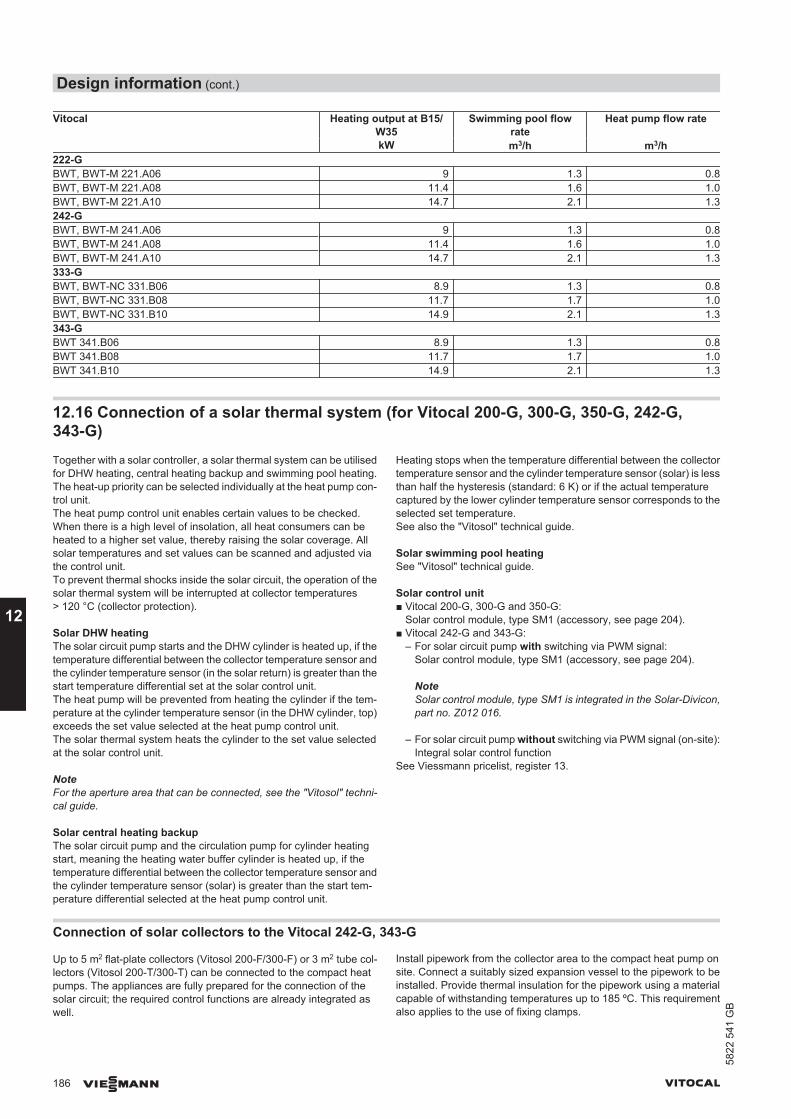
Vitocal Heating output at B15/W35
Swimming pool flowrate
Heat pump flow rate
kW m3/h m3/h222-GBWT, BWT-M 221.A06 9 1.3 0.8BWT, BWT-M 221.A08 11.4 1.6 1.0BWT, BWT-M 221.A10 14.7 2.1 1.3242-GBWT, BWT-M 241.A06 9 1.3 0.8BWT, BWT-M 241.A08 11.4 1.6 1.0BWT, BWT-M 241.A10 14.7 2.1 1.3333-GBWT, BWT-NC 331.B06 8.9 1.3 0.8BWT, BWT-NC 331.B08 11.7 1.7 1.0BWT, BWT-NC 331.B10 14.9 2.1 1.3343-GBWT 341.B06 8.9 1.3 0.8BWT 341.B08 11.7 1.7 1.0BWT 341.B10 14.9 2.1 1.3
12.16 Connection of a solar thermal system (for Vitocal 200-G, 300-G, 350-G, 242-G,343-G)Together with a solar controller, a solar thermal system can be utilisedfor DHW heating, central heating backup and swimming pool heating.The heat-up priority can be selected individually at the heat pump con-trol unit.The heat pump control unit enables certain values to be checked.When there is a high level of insolation, all heat consumers can beheated to a higher set value, thereby raising the solar coverage. Allsolar temperatures and set values can be scanned and adjusted viathe control unit.To prevent thermal shocks inside the solar circuit, the operation of thesolar thermal system will be interrupted at collector temperatures> 120 °C (collector protection).
Solar DHW heatingThe solar circuit pump starts and the DHW cylinder is heated up, if thetemperature differential between the collector temperature sensor andthe cylinder temperature sensor (in the solar return) is greater than thestart temperature differential set at the solar control unit.The heat pump will be prevented from heating the cylinder if the tem-perature at the cylinder temperature sensor (in the DHW cylinder, top)exceeds the set value selected at the heat pump control unit.The solar thermal system heats the cylinder to the set value selectedat the solar control unit.
NoteFor the aperture area that can be connected, see the "Vitosol" techni-cal guide.
Solar central heating backupThe solar circuit pump and the circulation pump for cylinder heatingstart, meaning the heating water buffer cylinder is heated up, if thetemperature differential between the collector temperature sensor andthe cylinder temperature sensor (solar) is greater than the start tem-perature differential selected at the heat pump control unit.
Heating stops when the temperature differential between the collectortemperature sensor and the cylinder temperature sensor (solar) is lessthan half the hysteresis (standard: 6 K) or if the actual temperaturecaptured by the lower cylinder temperature sensor corresponds to theselected set temperature.See also the "Vitosol" technical guide.
Solar swimming pool heatingSee "Vitosol" technical guide.
Solar control unit■ Vitocal 200-G, 300-G and 350-G:
Solar control module, type SM1 (accessory, see page 204).■ Vitocal 242-G and 343-G:
– For solar circuit pump with switching via PWM signal:Solar control module, type SM1 (accessory, see page 204).
NoteSolar control module, type SM1 is integrated in the Solar-Divicon,part no. Z012 016.
– For solar circuit pump without switching via PWM signal (on-site):Integral solar control function
See Viessmann pricelist, register 13.
Connection of solar collectors to the Vitocal 242-G, 343-G
Up to 5 m2 flat-plate collectors (Vitosol 200-F/300-F) or 3 m2 tube col-lectors (Vitosol 200-T/300-T) can be connected to the compact heatpumps. The appliances are fully prepared for the connection of thesolar circuit; the required control functions are already integrated aswell.
Install pipework from the collector area to the compact heat pump onsite. Connect a suitably sized expansion vessel to the pipework to beinstalled. Provide thermal insulation for the pipework using a materialcapable of withstanding temperatures up to 185 ºC. This requirementalso applies to the use of fixing clamps.
Design information (cont.)
186 VIESMANN VITOCAL
12
5822
541
GB
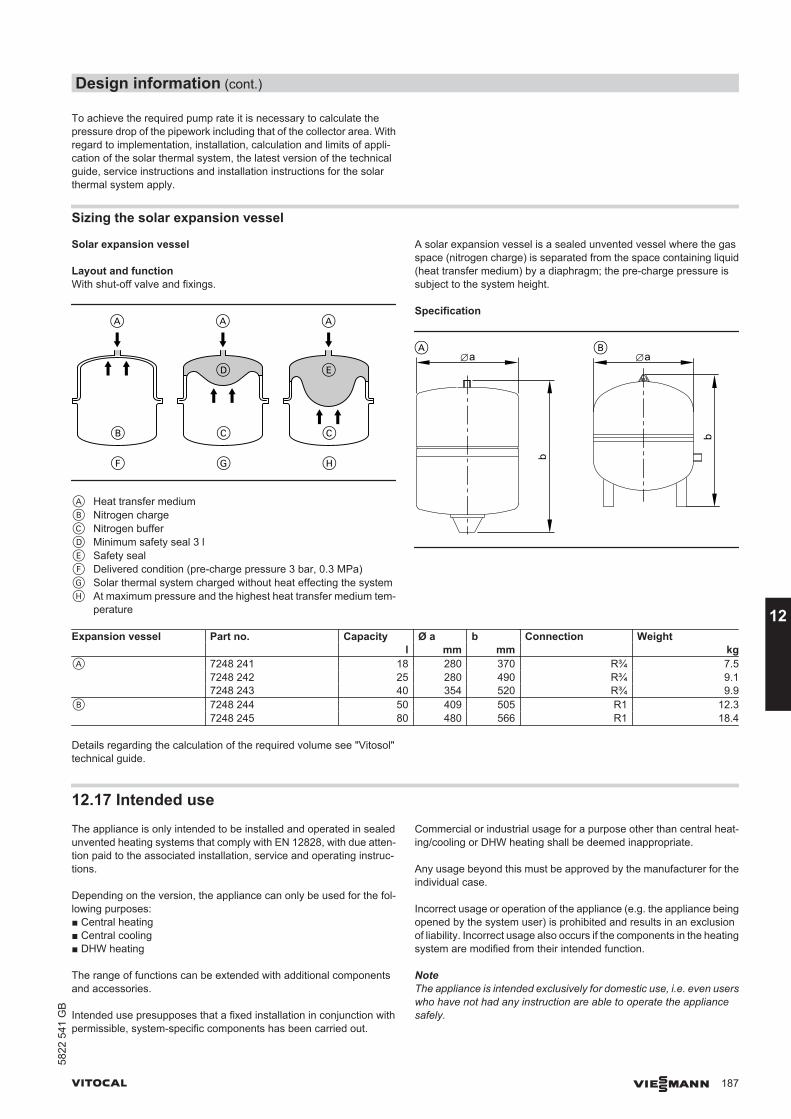
To achieve the required pump rate it is necessary to calculate thepressure drop of the pipework including that of the collector area. Withregard to implementation, installation, calculation and limits of appli-cation of the solar thermal system, the latest version of the technicalguide, service instructions and installation instructions for the solarthermal system apply.
Sizing the solar expansion vessel
Solar expansion vessel
Layout and functionWith shut-off valve and fixings.
A Heat transfer mediumB Nitrogen chargeC Nitrogen bufferD Minimum safety seal 3 lE Safety sealF Delivered condition (pre-charge pressure 3 bar, 0.3 MPa)G Solar thermal system charged without heat effecting the systemH At maximum pressure and the highest heat transfer medium tem-
perature
A solar expansion vessel is a sealed unvented vessel where the gasspace (nitrogen charge) is separated from the space containing liquid(heat transfer medium) by a diaphragm; the pre-charge pressure issubject to the system height.
Specification
b
b
a a
Expansion vessel Part no. Capacity Ø a b Connection Weight l mm mm kg
A 7248 241 18 280 370 R¾ 7.5 7248 242 25 280 490 R¾ 9.1 7248 243 40 354 520 R¾ 9.9B 7248 244 50 409 505 R1 12.3 7248 245 80 480 566 R1 18.4
Details regarding the calculation of the required volume see "Vitosol"technical guide.
12.17 Intended useThe appliance is only intended to be installed and operated in sealedunvented heating systems that comply with EN 12828, with due atten-tion paid to the associated installation, service and operating instruc-tions.
Depending on the version, the appliance can only be used for the fol-lowing purposes:■ Central heating■ Central cooling■ DHW heating
The range of functions can be extended with additional componentsand accessories.
Intended use presupposes that a fixed installation in conjunction withpermissible, system-specific components has been carried out.
Commercial or industrial usage for a purpose other than central heat-ing/cooling or DHW heating shall be deemed inappropriate.
Any usage beyond this must be approved by the manufacturer for theindividual case.
Incorrect usage or operation of the appliance (e.g. the appliance beingopened by the system user) is prohibited and results in an exclusionof liability. Incorrect usage also occurs if the components in the heatingsystem are modified from their intended function.
NoteThe appliance is intended exclusively for domestic use, i.e. even userswho have not had any instruction are able to operate the appliancesafely.
Design information (cont.)
VITOCAL VIESMANN 187
5822
541
GB
12
13.1 Vitotronic 200, type WO1C
Design and functions
Modular designThe control unit comprises the standard modules, PCBs and the pro-gramming unit.
Standard modules:■ ON/OFF switch■ Optolink interface■ Operating and fault display■ Fuses
PCBs for connecting external components:■ Connections for 230 V~ components, such as pumps, mixers etc.■ Connections for signal and safety components■ Connections for temperature sensors and KM BUS
Programming unit■ Straight forward operation:
– Plain text display with graphic ability– Large font and black/white depiction for good contrast– Context-sensitive help texts
■ With time switch■ Operating keys:
– Navigation– Confirmation– Help– Extended menu
■ Settings:– Standard and reduced room temperature– Standard and second DHW temperature– Operating program– Time programs, e.g. for central heating, DHW heating, DHW cir-
culation and heating water buffer cylinder– Economy mode– Party mode– Holiday program– Heating and cooling curves– Parameter
■ Display:– Flow temperatures– DHW temperature– Information– Operating data– Diagnostic details– Information, warning and fault messages
■ Available languages:– German– Bulgarian– Czech– Danish– English– Spanish– Estonian– French– Croatian– Italian– Latvian– Lithuanian– Hungarian– Dutch– Polish– Russian– Romanian– Slovenian– Finnish– Swedish– Turkish
Functions
■ Electronic maximum and minimum temperature limit■ Demand-dependent shutdown of the heat pump and the pumps for
the primary and secondary circuits■ Adjustment of a variable heating and cooling limit■ Anti-seizing pump protection■ Monitoring frost protection of system components■ Integral diagnostic system■ Cylinder temperature controller with priority control■ Auxiliary function for DHW heating (short-term heating to a higher
temperature)■ Control of a heating water buffer cylinder■ Screed drying program■ External hook-up: Mixer OPEN, mixer CLOSE, changeover of oper-
ating mode (with external EA1 extension, accessory)■ External demand (adjustable set flow temperature) and heat pump
power-OFF, specifying the set flow temperature via an external 0 to10 V signal (with external EA1 extension, accessory)
■ Function check of controlled components, e.g. circulation pumps■ Optimised utilisation of power generated by the photovoltaic system
(on-site power consumption)■ Control and operation of the Vitovent 300-F ventilation unit
Heat pump control unit, type WO1C
188 VIESMANN VITOCAL
1358
22 5
41 G
B
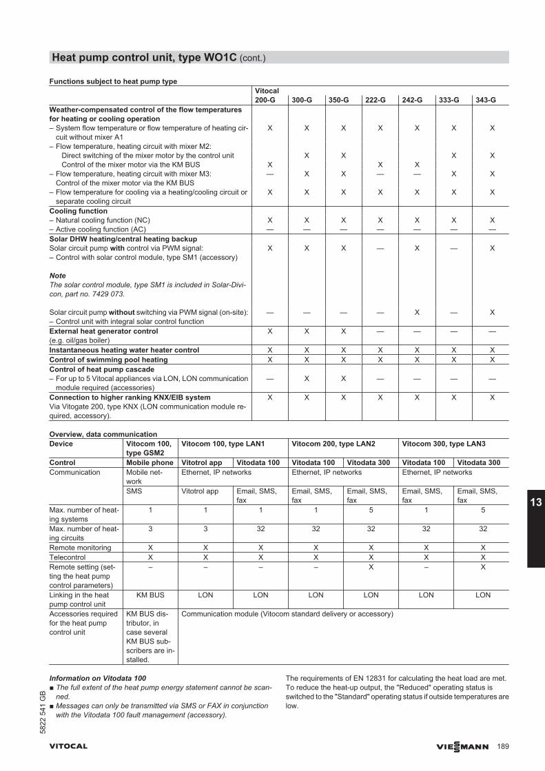
Functions subject to heat pump type Vitocal
200-G 300-G 350-G 222-G 242-G 333-G 343-GWeather-compensated control of the flow temperaturesfor heating or cooling operation
– System flow temperature or flow temperature of heating cir-cuit without mixer A1
X X X X X X X
– Flow temperature, heating circuit with mixer M2: Direct switching of the mixer motor by the control unit X X X X Control of the mixer motor via the KM BUS X X X – Flow temperature, heating circuit with mixer M3:
Control of the mixer motor via the KM BUS— X X — — X X
– Flow temperature for cooling via a heating/cooling circuit orseparate cooling circuit
X X X X X X X
Cooling function – Natural cooling function (NC) X X X X X X X– Active cooling function (AC) — — — — — — —Solar DHW heating/central heating backup Solar circuit pump with control via PWM signal:– Control with solar control module, type SM1 (accessory)
NoteThe solar control module, type SM1 is included in Solar-Divi-con, part no. 7429 073.
X X X — X — X
Solar circuit pump without switching via PWM signal (on-site):– Control unit with integral solar control function
— — — — X — X
External heat generator control(e.g. oil/gas boiler)
X X X — — — —
Instantaneous heating water heater control X X X X X X XControl of swimming pool heating X X X X X X XControl of heat pump cascade – For up to 5 Vitocal appliances via LON, LON communication
module required (accessories)— X X — — — —
Connection to higher ranking KNX/EIB systemVia Vitogate 200, type KNX (LON communication module re-quired, accessory).
X X X X X X X
Overview, data communicationDevice Vitocom 100,
type GSM2Vitocom 100, type LAN1 Vitocom 200, type LAN2 Vitocom 300, type LAN3
Control Mobile phone Vitotrol app Vitodata 100 Vitodata 100 Vitodata 300 Vitodata 100 Vitodata 300Communication Mobile net-
workEthernet, IP networks Ethernet, IP networks Ethernet, IP networks
SMS Vitotrol app Email, SMS,fax
Email, SMS,fax
Email, SMS,fax
Email, SMS,fax
Email, SMS,fax
Max. number of heat-ing systems
1 1 1 1 5 1 5
Max. number of heat-ing circuits
3 3 32 32 32 32 32
Remote monitoring X X X X X X XTelecontrol X X X X X X XRemote setting (set-ting the heat pumpcontrol parameters)
– – – – X – X
Linking in the heatpump control unit
KM BUS LON LON LON LON LON LON
Accessories requiredfor the heat pumpcontrol unit
KM BUS dis-tributor, incase severalKM BUS sub-scribers are in-stalled.
Communication module (Vitocom standard delivery or accessory)
Information on Vitodata 100■ The full extent of the heat pump energy statement cannot be scan-
ned.■ Messages can only be transmitted via SMS or FAX in conjunction
with the Vitodata 100 fault management (accessory).
The requirements of EN 12831 for calculating the heat load are met.To reduce the heat-up output, the "Reduced" operating status isswitched to the "Standard" operating status if outside temperatures arelow.
Heat pump control unit, type WO1C (cont.)
VITOCAL VIESMANN 189
5822
541
GB
13
According to the [German] Energy Saving Ordinance, the temperaturein each room must be individually controlled, e.g. by means of ther-mostatic valves.
Time switch
Digital time switch (integrated into the programming unit)■ Individual day and seven-day program■ Automatic summer/wintertime changeover■ Automatic function for DHW heating and DHW circulation pump■ Standard switching times are preset at the factory, e.g. for central
heating, DHW heating, charging a heating water buffer cylinder andswitching the DHW circulation pump.
■ Time program is individually adjustable; up to 8 time phases per dayShortest switching interval: 10 minPower reserve: 14 days
Setting the operating programsFrost protection monitoring for the system components is enabled inall operating programs (see frost protection function).You can select the following operating programs via the menu:■ For heating/cooling circuits:
"Heating and DHW" or "heating, cooling and DHW"■ For a separate cooling circuit:
"Cooling"■ "Only DHW"; separate settings for each heating circuit
NoteIf the heat pump only needs to be on for DHW heating (e.g. in thesummer), the operating program "Only DHW" must be selected forall heating circuits.
■ "Standby mode"Frost protection only
The operating programs can also be switched over externally, e.g. byVitocom 100.
Frost protection function■ If the outside temperature falls below +1 °C, the frost protection
function is switched on.With active frost protection, the heating circuit pump will be switchedon and the flow temperature in the secondary circuit will be main-tained at a lower temperature of approx. 20 °C.The DHW cylinder will be heated to approx. 20 °C.
■ If the outside temperature exceeds +3 °C, the frost protection func-tion is switched off.
Heating and cooling curve settings (slope and level)
The Vitotronic 200 regulates the flow temperatures for the heating/cooling circuits in weather-compensated mode:■ System flow temperature or flow temperature of heating circuit with-
out mixer A1■ Flow temperature, heating circuit with mixer M2:
Depending on the heat pump, the mixer motor is controlled eitherdirectly by the control unit or via the KM BUS.
■ Flow temperature, heating circuit with mixer M3:Not available with every heat pump; mixer motor switching via theKM BUS.
■ Flow temperature for cooling via heating circuit; the regulation of theseparate cooling circuit is room temperature-dependent.
The flow temperature required to reach a specific room temperaturedepends on the heating system and the thermal insulation of the build-ing to be heated or cooled.Adjusting the heating or cooling curves matches the flow temperatureto these conditions.
■ Heating curves:The flow temperature of the secondary circuit is restricted at theupper end of the scale by the temperature limiter and the maximumtemperature set at the heat pump control unit.
Heat pump control unit, type WO1C (cont.)
190 VIESMANN VITOCAL
1358
22 5
41 G
B
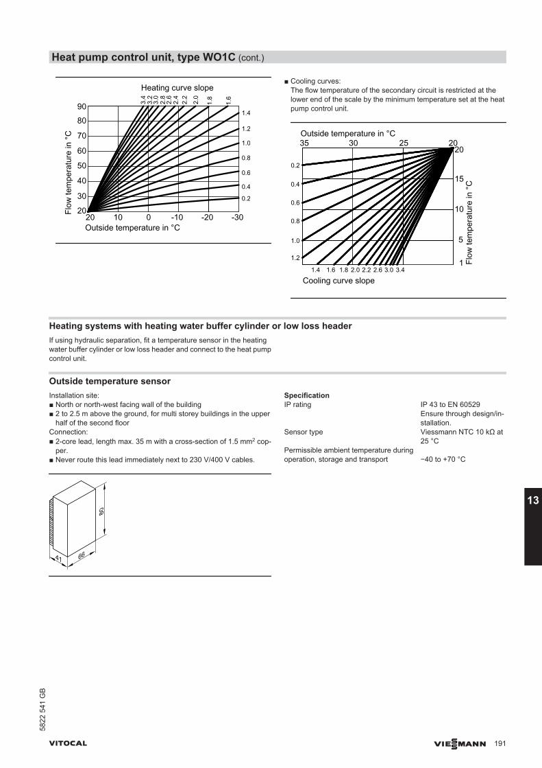
3.2
3.4
Flow
tem
pera
ture
in °
C
Outside temperature in °C
Heating curve slope
3.0
2.8
2.2
2.4
2.0
1.6
1.4
1.2
1.0
0.8
0.6
0.4
0.2
90
80
70
60
50
40
30
201.
8
2.6
1020 -30-20-100
■ Cooling curves:The flow temperature of the secondary circuit is restricted at thelower end of the scale by the minimum temperature set at the heatpump control unit.
1.2
30 25 2035Outside temperature in °C
Flow
tem
pera
ture
in °
C
1
5
10
15
20
1.4 1.6
1.0
0.8
0.6
0.4
0.2
1.8 2.0 2.2 3.43.02.6
Cooling curve slope
Heating systems with heating water buffer cylinder or low loss headerIf using hydraulic separation, fit a temperature sensor in the heatingwater buffer cylinder or low loss header and connect to the heat pumpcontrol unit.
Outside temperature sensorInstallation site:■ North or north-west facing wall of the building■ 2 to 2.5 m above the ground, for multi storey buildings in the upper
half of the second floorConnection:■ 2-core lead, length max. 35 m with a cross-section of 1.5 mm2 cop-
per.■ Never route this lead immediately next to 230 V/400 V cables.
41 66
80
SpecificationIP rating IP 43 to EN 60529
Ensure through design/in-stallation.
Sensor type Viessmann NTC 10 kΩ at25 °C
Permissible ambient temperature duringoperation, storage and transport −40 to +70 °C
Heat pump control unit, type WO1C (cont.)
VITOCAL VIESMANN 191
5822
541
GB
13
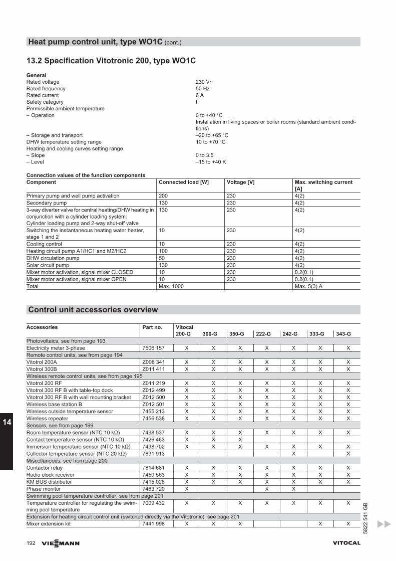
13.2 Specification Vitotronic 200, type WO1CGeneralRated voltage 230 V~Rated frequency 50 HzRated current 6 ASafety category IPermissible ambient temperature – Operation 0 to +40 °C
Installation in living spaces or boiler rooms (standard ambient condi-tions)
– Storage and transport –20 to +65 °CDHW temperature setting range 10 to +70 °CHeating and cooling curves setting range – Slope 0 to 3.5– Level –15 to +40 K
Connection values of the function componentsComponent Connected load [W] Voltage [V] Max. switching current
[A]Primary pump and well pump activation 200 230 4(2)Secondary pump 130 230 4(2)3-way diverter valve for central heating/DHW heating inconjunction with a cylinder loading system:Cylinder loading pump and 2-way shut-off valve
130 230 4(2)
Switching the instantaneous heating water heater,stage 1 and 2
10 230 4(2)
Cooling control 10 230 4(2)Heating circuit pump A1/HC1 and M2/HC2 100 230 4(2)DHW circulation pump 50 230 4(2)Solar circuit pump 130 230 4(2)Mixer motor activation, signal mixer CLOSED 10 230 0.2(0.1)Mixer motor activation, signal mixer OPEN 10 230 0.2(0.1)Total Max. 1000 Max. 5(3) A
Control unit accessories overview
Accessories Part no. Vitocal 200-G 300-G 350-G 222-G 242-G 333-G 343-GPhotovoltaics, see from page 193Electricity meter 3-phase 7506 157 X X X X X X XRemote control units, see from page 194Vitotrol 200A Z008 341 X X X X X X XVitotrol 300B Z011 411 X X X X X X XWireless remote control units, see from page 195Vitotrol 200 RF Z011 219 X X X X X X XVitotrol 300 RF B with table-top dock Z012 499 X X X X X X XVitotrol 300 RF B with wall mounting bracket Z012 500 X X X X X X XWireless base station B Z012 501 X X X X X X XWireless outside temperature sensor 7455 213 X X X X X X XWireless repeater 7456 538 X X X X X X XSensors, see from page 199Room temperature sensor (NTC 10 kΩ) 7438 537 X X X X X X XContact temperature sensor (NTC 10 kΩ) 7426 463 X X X Immersion temperature sensor (NTC 10 kΩ) 7438 702 X X X X X X XCollector temperature sensor (NTC 20 kΩ) 7831 913 X XMiscellaneous, see from page 200Contactor relay 7814 681 X X X X X X XRadio clock receiver 7450 563 X X X X X X XKM BUS distributor 7415 028 X X X X X X XPhase monitor 7463 720 X X X Swimming pool temperature controller, see from page 201Temperature controller for regulating the swim-ming pool temperature
7009 432 X X X X X X X
Extension for heating circuit control unit (switched directly via the Vitotronic), see page 201Mixer extension kit 7441 998 X X X X X
Heat pump control unit, type WO1C (cont.)
192 VIESMANN VITOCAL
14
5822
541
GB
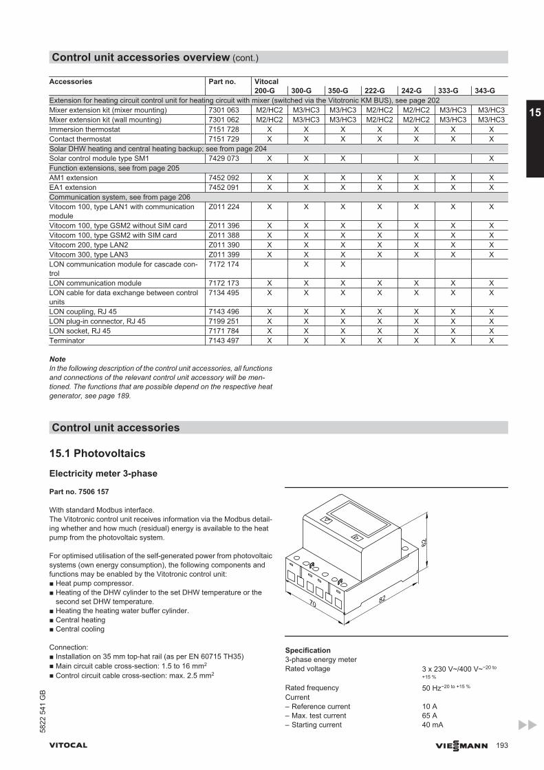
Accessories Part no. Vitocal 200-G 300-G 350-G 222-G 242-G 333-G 343-GExtension for heating circuit control unit for heating circuit with mixer (switched via the Vitotronic KM BUS), see page 202Mixer extension kit (mixer mounting) 7301 063 M2/HC2 M3/HC3 M3/HC3 M2/HC2 M2/HC2 M3/HC3 M3/HC3Mixer extension kit (wall mounting) 7301 062 M2/HC2 M3/HC3 M3/HC3 M2/HC2 M2/HC2 M3/HC3 M3/HC3Immersion thermostat 7151 728 X X X X X X XContact thermostat 7151 729 X X X X X X XSolar DHW heating and central heating backup; see from page 204Solar control module type SM1 7429 073 X X X X XFunction extensions, see from page 205AM1 extension 7452 092 X X X X X X XEA1 extension 7452 091 X X X X X X XCommunication system, see from page 206Vitocom 100, type LAN1 with communicationmodule
Z011 224 X X X X X X X
Vitocom 100, type GSM2 without SIM card Z011 396 X X X X X X XVitocom 100, type GSM2 with SIM card Z011 388 X X X X X X XVitocom 200, type LAN2 Z011 390 X X X X X X XVitocom 300, type LAN3 Z011 399 X X X X X X XLON communication module for cascade con-trol
7172 174 X X
LON communication module 7172 173 X X X X X X XLON cable for data exchange between controlunits
7134 495 X X X X X X X
LON coupling, RJ 45 7143 496 X X X X X X XLON plug-in connector, RJ 45 7199 251 X X X X X X XLON socket, RJ 45 7171 784 X X X X X X XTerminator 7143 497 X X X X X X X
NoteIn the following description of the control unit accessories, all functionsand connections of the relevant control unit accessory will be men-tioned. The functions that are possible depend on the respective heatgenerator, see page 189.
Control unit accessories
15.1 Photovoltaics
Electricity meter 3-phase
Part no. 7506 157
With standard Modbus interface.The Vitotronic control unit receives information via the Modbus detail-ing whether and how much (residual) energy is available to the heatpump from the photovoltaic system.
For optimised utilisation of the self-generated power from photovoltaicsystems (own energy consumption), the following components andfunctions may be enabled by the Vitotronic control unit:■ Heat pump compressor.■ Heating of the DHW cylinder to the set DHW temperature or the
second set DHW temperature.■ Heating the heating water buffer cylinder.■ Central heating■ Central cooling
Connection:■ Installation on 35 mm top-hat rail (as per EN 60715 TH35)■ Main circuit cable cross-section: 1.5 to 16 mm2
■ Control circuit cable cross-section: max. 2.5 mm2
70 82
62
Specification3-phase energy meterRated voltage 3 x 230 V~/400 V~−20 to
+15 %
Rated frequency 50 Hz−20 to +15 %
Current – Reference current 10 A– Max. test current 65 A– Starting current 40 mA
Control unit accessories overview (cont.)
VITOCAL VIESMANN 193
5822
541
GB
15
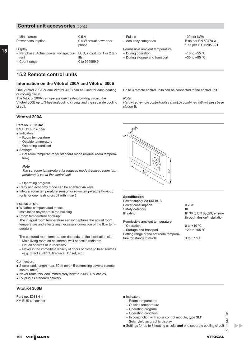
– Min. current 0.5 APower consumption 0.4 W actual power per
phaseDisplay – Per phase: Actual power, voltage, cur-
rentLCD, 7-digit, for 1 or 2 tar-iffs
– Count range 0 to 999999.9
– Pulses 100 per kWh– Accuracy categories B as per EN 50470-3
1 as per IEC 62053-21Permissible ambient temperature – During operation −10 to +55 °C– During storage and transport −30 to +85 °C
15.2 Remote control units
Information on the Vitotrol 200A and Vitotrol 300BOne Vitotrol 200A or one Vitotrol 300B can be used for each heatingor cooling circuit.The Vitotrol 200A can operate one heating/cooling circuit; theVitotrol 300B up to 3 heating/cooling circuits and the separate coolingcircuit.
Up to 3 remote control units can be connected to the control unit.
NoteHardwired remote control units cannot be combined with wireless basestation B.
Vitotrol 200A
Part no. Z008 341KM BUS subscriber■ Indicators:
– Room temperature– Outside temperature– Operating condition
■ Settings:– Set room temperature for standard mode (normal room tempera-
ture)
NoteThe set room temperature for reduced mode (reduced room tem-perature) is set at the control unit.
– Operating program■ Party and economy mode can be enabled via keys■ Integral room temperature sensor for room temperature hook-up
(only for one heating circuit with mixer)
Installation site:■ Weather-compensated mode:
Installation anywhere in the building■ Room temperature hook-up:
The integral room temperature sensor captures the actual roomtemperature and effects any necessary correction of the flow tem-perature.
The captured room temperature depends on the installation site:– Main living room on an internal wall opposite radiators– Not on shelves or in recesses– Never in the immediate vicinity of doors or close to heat sources
(e.g. direct sunlight, fireplace, TV set, etc.)
Connection:■ 2-core lead, length max. 50 m (even if connecting several remote
control units)■ Never route this lead immediately next to 230/400 V cables■ LV plug as standard delivery
148
20,5
97
SpecificationPower supply via KM BUSPower consumption 0.2 WSafety category IIIIP rating IP 30 to EN 60529; ensure
through design/installationPermissible ambient temperature– Operation 0 to +40 °C– Storage and transport −20 to +65 °CSetting range of the set room tempera-ture for standard mode 3 to 37 °C
Vitotrol 300B
Part no. Z011 411KM BUS subscriber
■ Indicators:– Room temperature– Outside temperature– Operating program– Operating condition– In conjunction with solar control module, type SM1:
Solar yield as graphic display■ Settings for up to 3 heating circuits and one separate cooling circuit
Control unit accessories (cont.)
194 VIESMANN VITOCAL
15
5822
541
GB
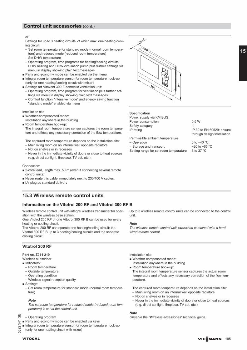
orSettings for up to 3 heating circuits, of which max. one heating/cool-ing circuit:– Set room temperature for standard mode (normal room tempera-
ture) and reduced mode (reduced room temperature)– Set DHW temperature– Operating program, time programs for heating/cooling circuits,
DHW heating and DHW circulation pump plus further settings viamenu in display showing plain text messages
■ Party and economy mode can be enabled via the menu■ Integral room temperature sensor for room temperature hook-up
(only for one heating/cooling circuit with mixer)■ Settings for Vitovent 300-F domestic ventilation unit:
– Operating program, time program for ventilation plus further set-tings via menu in display showing plain text messages
– Comfort function "intensive mode" and energy saving function"standard mode" enabled via menu
Installation site:■ Weather-compensated mode:
Installation anywhere in the building■ Room temperature hook-up:
The integral room temperature sensor captures the room tempera-ture and effects any necessary correction of the flow temperature.
The captured room temperature depends on the installation site:– Main living room on an internal wall opposite radiators– Not on shelves or in recesses– Never in the immediate vicinity of doors or close to heat sources
(e.g. direct sunlight, fireplace, TV set, etc.).
Connection:■ 2-core lead, length max. 50 m (even if connecting several remote
control units)■ Never route this cable immediately next to 230/400 V cables.■ LV plug as standard delivery
20,5
155 97
SpecificationPower supply via KM BUSPower consumption 0.5 WSafety category IIIIP rating IP 30 to EN 60529; ensure
through design/installationPermissible ambient temperature– Operation 0 to +40 °C– Storage and transport −20 to +65 °CSetting range for set room temperature 3 to 37 °C
15.3 Wireless remote control units
Information on the Vitotrol 200 RF and Vitotrol 300 RF BWireless remote control unit with integral wireless transmitter for oper-ation with the wireless base station.One Vitotrol 200 RF or one Vitotrol 300 RF B can be used for everyheating or cooling circuit.The Vitotrol 200 RF can operate one heating/cooling circuit; theVitotrol 300 RF B up to 3 heating/cooling circuits and the separatecooling circuit.
Up to 3 wireless remote control units can be connected to the controlunit.
NoteThe wireless remote control unit cannot be combined with a hard-wired remote control.
Vitotrol 200 RF
Part no. Z011 219Wireless subscriber■ Indicators:
– Room temperature– Outside temperature– Operating condition– Wireless signal reception quality
■ Settings:– Set room temperature for standard mode (normal room tempera-
ture)
NoteThe set room temperature for reduced mode (reduced room tem-perature) is set at the control unit.
– Operating program■ Party and economy mode can be enabled via keys■ Integral room temperature sensor for room temperature hook-up
(only for one heating circuit with mixer)
Installation site:■ Weather-compensated mode:
Installation anywhere in the building■ Room temperature hook-up:
The integral room temperature sensor captures the actual roomtemperature and effects any necessary correction of the flow tem-perature.
The captured room temperature depends on the installation site:– Main living room on an internal wall opposite radiators– Not on shelves or in recesses– Never in the immediate vicinity of doors or close to heat sources
(e.g. direct sunlight, fireplace, TV set, etc.)
NoteObserve the "Wireless accessories" technical guide.
Control unit accessories (cont.)
VITOCAL VIESMANN 195
5822
541
GB
15
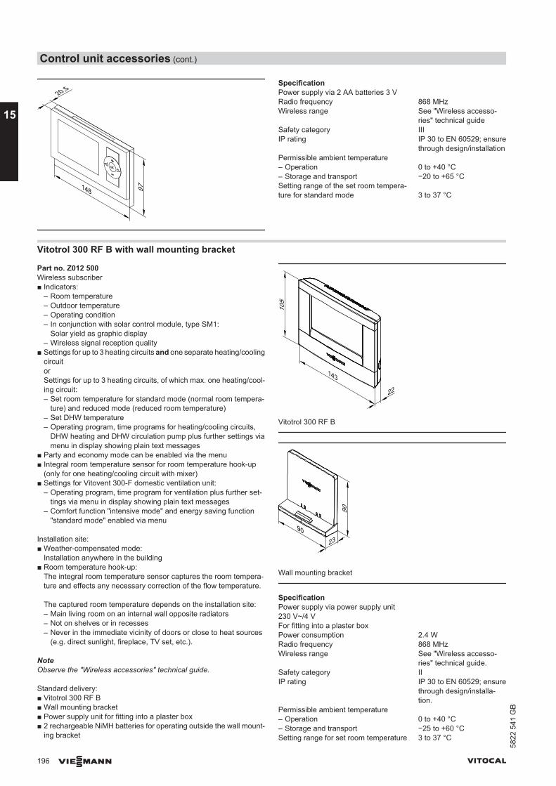
148
20,5
97
SpecificationPower supply via 2 AA batteries 3 VRadio frequency 868 MHzWireless range See "Wireless accesso-
ries" technical guideSafety category IIIIP rating IP 30 to EN 60529; ensure
through design/installationPermissible ambient temperature– Operation 0 to +40 °C– Storage and transport −20 to +65 °CSetting range of the set room tempera-ture for standard mode 3 to 37 °C
Vitotrol 300 RF B with wall mounting bracket
Part no. Z012 500Wireless subscriber■ Indicators:
– Room temperature– Outdoor temperature– Operating condition– In conjunction with solar control module, type SM1:
Solar yield as graphic display– Wireless signal reception quality
■ Settings for up to 3 heating circuits and one separate heating/coolingcircuitorSettings for up to 3 heating circuits, of which max. one heating/cool-ing circuit:– Set room temperature for standard mode (normal room tempera-
ture) and reduced mode (reduced room temperature)– Set DHW temperature– Operating program, time programs for heating/cooling circuits,
DHW heating and DHW circulation pump plus further settings viamenu in display showing plain text messages
■ Party and economy mode can be enabled via the menu■ Integral room temperature sensor for room temperature hook-up
(only for one heating/cooling circuit with mixer)■ Settings for Vitovent 300-F domestic ventilation unit:
– Operating program, time program for ventilation plus further set-tings via menu in display showing plain text messages
– Comfort function "intensive mode" and energy saving function"standard mode" enabled via menu
Installation site:■ Weather-compensated mode:
Installation anywhere in the building■ Room temperature hook-up:
The integral room temperature sensor captures the room tempera-ture and effects any necessary correction of the flow temperature.
The captured room temperature depends on the installation site:– Main living room on an internal wall opposite radiators– Not on shelves or in recesses– Never in the immediate vicinity of doors or close to heat sources
(e.g. direct sunlight, fireplace, TV set, etc.).
NoteObserve the "Wireless accessories" technical guide.
Standard delivery:■ Vitotrol 300 RF B■ Wall mounting bracket■ Power supply unit for fitting into a plaster box■ 2 rechargeable NiMH batteries for operating outside the wall mount-
ing bracket
143
22
105
Vitotrol 300 RF B
23
90
90
Wall mounting bracket
SpecificationPower supply via power supply unit 230 V~/4 VFor fitting into a plaster box
Power consumption 2.4 WRadio frequency 868 MHzWireless range See "Wireless accesso-
ries" technical guide.Safety category IIIP rating IP 30 to EN 60529; ensure
through design/installa-tion.
Permissible ambient temperature– Operation 0 to +40 °C– Storage and transport −25 to +60 °CSetting range for set room temperature 3 to 37 °C
Control unit accessories (cont.)
196 VIESMANN VITOCAL
15
5822
541
GB
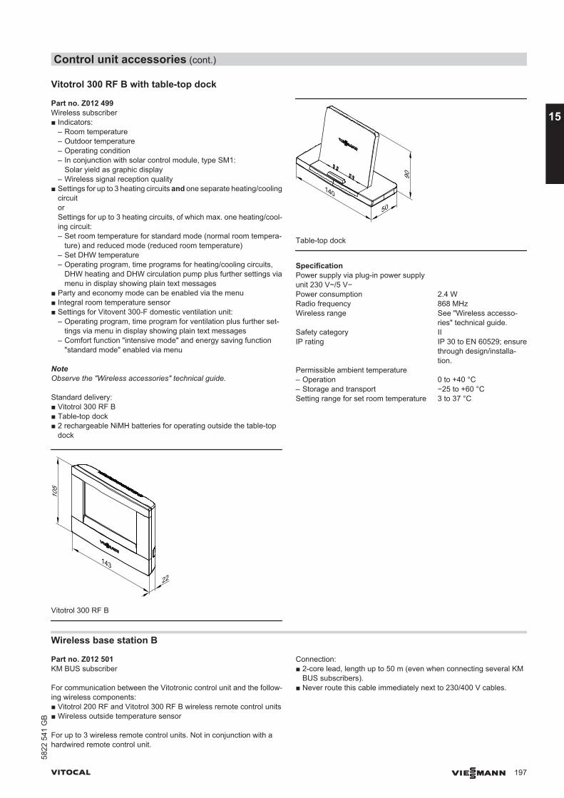
Vitotrol 300 RF B with table-top dock
Part no. Z012 499Wireless subscriber■ Indicators:
– Room temperature– Outdoor temperature– Operating condition– In conjunction with solar control module, type SM1:
Solar yield as graphic display– Wireless signal reception quality
■ Settings for up to 3 heating circuits and one separate heating/coolingcircuitorSettings for up to 3 heating circuits, of which max. one heating/cool-ing circuit:– Set room temperature for standard mode (normal room tempera-
ture) and reduced mode (reduced room temperature)– Set DHW temperature– Operating program, time programs for heating/cooling circuits,
DHW heating and DHW circulation pump plus further settings viamenu in display showing plain text messages
■ Party and economy mode can be enabled via the menu■ Integral room temperature sensor■ Settings for Vitovent 300-F domestic ventilation unit:
– Operating program, time program for ventilation plus further set-tings via menu in display showing plain text messages
– Comfort function "intensive mode" and energy saving function"standard mode" enabled via menu
NoteObserve the "Wireless accessories" technical guide.
Standard delivery:■ Vitotrol 300 RF B■ Table-top dock■ 2 rechargeable NiMH batteries for operating outside the table-top
dock
143
22
105
Vitotrol 300 RF B
140
50
90
Table-top dock
SpecificationPower supply via plug-in power supplyunit 230 V~/5 V−
Power consumption 2.4 WRadio frequency 868 MHzWireless range See "Wireless accesso-
ries" technical guide.Safety category IIIP rating IP 30 to EN 60529; ensure
through design/installa-tion.
Permissible ambient temperature– Operation 0 to +40 °C– Storage and transport −25 to +60 °CSetting range for set room temperature 3 to 37 °C
Wireless base station B
Part no. Z012 501KM BUS subscriber
For communication between the Vitotronic control unit and the follow-ing wireless components:■ Vitotrol 200 RF and Vitotrol 300 RF B wireless remote control units■ Wireless outside temperature sensor
For up to 3 wireless remote control units. Not in conjunction with ahardwired remote control unit.
Connection:■ 2-core lead, length up to 50 m (even when connecting several KM
BUS subscribers).■ Never route this cable immediately next to 230/400 V cables.
Control unit accessories (cont.)
VITOCAL VIESMANN 197
5822
541
GB
15
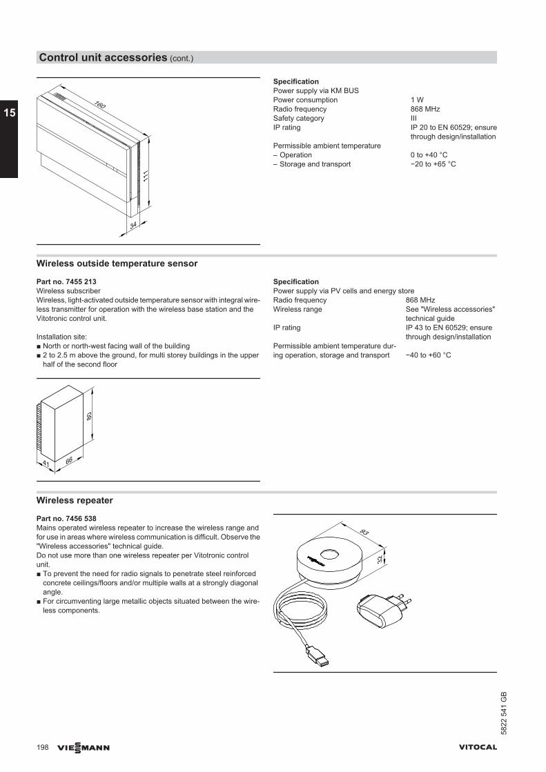
160
34
111
SpecificationPower supply via KM BUSPower consumption 1 WRadio frequency 868 MHzSafety category IIIIP rating IP 20 to EN 60529; ensure
through design/installationPermissible ambient temperature– Operation 0 to +40 °C– Storage and transport −20 to +65 °C
Wireless outside temperature sensor
Part no. 7455 213Wireless subscriberWireless, light-activated outside temperature sensor with integral wire-less transmitter for operation with the wireless base station and theVitotronic control unit.
Installation site:■ North or north-west facing wall of the building■ 2 to 2.5 m above the ground, for multi storey buildings in the upper
half of the second floor
41 66
80
SpecificationPower supply via PV cells and energy storeRadio frequency 868 MHzWireless range See "Wireless accessories"
technical guideIP rating IP 43 to EN 60529; ensure
through design/installationPermissible ambient temperature dur-ing operation, storage and transport −40 to +60 °C
Wireless repeater
Part no. 7456 538Mains operated wireless repeater to increase the wireless range andfor use in areas where wireless communication is difficult. Observe the"Wireless accessories" technical guide.Do not use more than one wireless repeater per Vitotronic controlunit.■ To prevent the need for radio signals to penetrate steel reinforced
concrete ceilings/floors and/or multiple walls at a strongly diagonalangle.
■ For circumventing large metallic objects situated between the wire-less components.
93
32
Control unit accessories (cont.)
198 VIESMANN VITOCAL
15
5822
541
GB

SpecificationPower supply 230 V~/5 V− via plug-in
power supply unitPower consumption 0.25 WRadio frequency 868 MHzCable length 1.1 m with plug
Safety category IIIP rating IP 20 to EN 60529; ensure
through design/installationPermissible ambient temperature– Operation 0 to +55 °C– Storage and transport −20 to +75 °C
15.4 Sensors
Room temperature sensor
Part no. 7438 537Separate room temperature sensor as supplement to the Vitotrol300A; to be used if the Vitotrol 300A cannot be installed inside the mainliving room or in a suitable position where the unit could capture andadjust the temperature.Installation in the main living room on an internal wall, opposite radia-tors. Never install inside shelving units, in recesses, or immediately bya door or heat source (e.g. direct sunlight, fireplace, TV set, etc.).Connect the room temperature sensor to the Vitotrol 300A.Connection:■ 2-core lead with a cross-section of 1.5 mm2 (copper)■ Lead length from the remote control up to 30 m■ Never route this lead immediately next to 230/400 V cables
20
80□
SpecificationSafety category IIIIP rating IP 30 to EN 60529; ensure
through design/installationSensor type Viessmann NTC 10 kΩ at
25 °CPermissible ambient temperature– Operation 0 to +40 °C– Storage and transport −20 to +65 °C
Contact temperature sensor
Part no. 7426 463To capture the temperature on a pipe.
42
66
60
Secured with a tie.
SpecificationCable length 5.8 m, fully wiredIP rating IP 32D to EN 60529; ensure
through design/installationSensor type Viessmann NTC 10 kΩ at
25 °CPermissible ambient temperature – Operation 0 to +120 °C– Storage and transport –20 to +70 °C
Immersion temperature sensor
Part no. 7438 702To capture the temperature in a sensor well.
SpecificationCable length 5.8 m, fully wiredIP rating IP 32 to EN 60529; ensure
through design/installationSensor type Viessmann NTC 10 kΩ, at
25 °CPermissible ambient temperature– Operation 0 to +90 °C– Storage and transport −20 to +70 °C
Control unit accessories (cont.)
VITOCAL VIESMANN 199
5822
541
GB
15
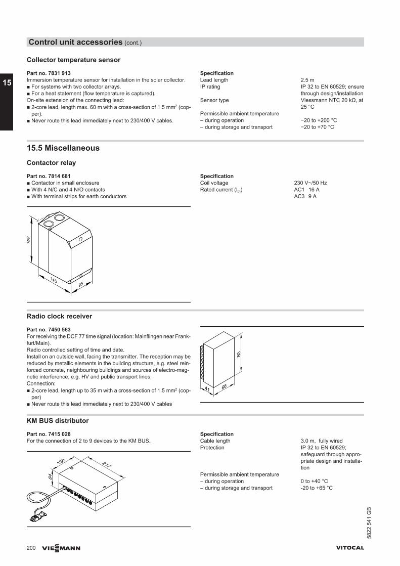
Collector temperature sensor
Part no. 7831 913Immersion temperature sensor for installation in the solar collector.■ For systems with two collector arrays.■ For a heat statement (flow temperature is captured).On-site extension of the connecting lead:■ 2-core lead, length max. 60 m with a cross-section of 1.5 mm2 (cop-
per).■ Never route this lead immediately next to 230/400 V cables.
SpecificationLead length 2.5 mIP rating IP 32 to EN 60529; ensure
through design/installationSensor type Viessmann NTC 20 kΩ, at
25 °CPermissible ambient temperature– during operation −20 to +200 °C– during storage and transport −20 to +70 °C
15.5 Miscellaneous
Contactor relay
Part no. 7814 681■ Contactor in small enclosure■ With 4 N/C and 4 N/O contacts■ With terminal strips for earth conductors
95145
180
SpecificationCoil voltage 230 V~/50 HzRated current (Ith) AC1 16 A
AC3 9 A
Radio clock receiver
Part no. 7450 563For receiving the DCF 77 time signal (location: Mainflingen near Frank-furt/Main).Radio controlled setting of time and date.Install on an outside wall, facing the transmitter. The reception may bereduced by metallic elements in the building structure, e.g. steel rein-forced concrete, neighbouring buildings and sources of electro-mag-netic interference, e.g. HV and public transport lines.Connection:■ 2-core lead, length up to 35 m with a cross-section of 1.5 mm2 (cop-
per)■ Never route this lead immediately next to 230/400 V cables
41 66
80
KM BUS distributor
Part no. 7415 028For the connection of 2 to 9 devices to the KM BUS.
217130
84
SpecificationCable length 3.0 m, fully wiredProtection IP 32 to EN 60529;
safeguard through appro-priate design and installa-tion
Permissible ambient temperature– during operation 0 to +40 °C– during storage and transport -20 to +65 °C
Control unit accessories (cont.)
200 VIESMANN VITOCAL
15
5822
541
GB
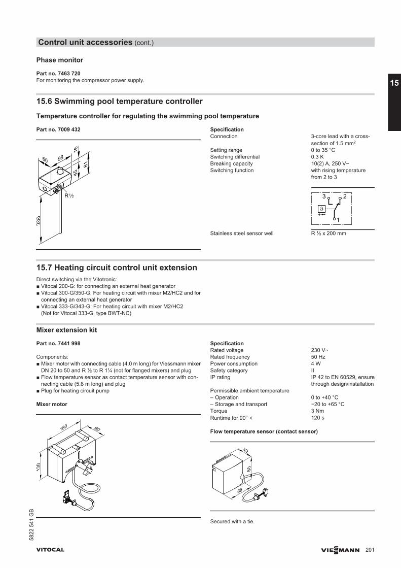
Phase monitor
Part no. 7463 720For monitoring the compressor power supply.
15.6 Swimming pool temperature controller
Temperature controller for regulating the swimming pool temperature
Part no. 7009 432
9860
1645
61
200
R
SpecificationConnection 3-core lead with a cross-
section of 1.5 mm2
Setting range 0 to 35 °CSwitching differential 0.3 KBreaking capacity 10(2) A, 250 V~Switching function with rising temperature
from 2 to 3
3 2
1
Stainless steel sensor well R ½ x 200 mm
15.7 Heating circuit control unit extensionDirect switching via the Vitotronic:■ Vitocal 200-G: for connecting an external heat generator■ Vitocal 300-G/350-G: For heating circuit with mixer M2/HC2 and for
connecting an external heat generator■ Vitocal 333-G/343-G: For heating circuit with mixer M2/HC2
(Not for Vitocal 333-G, type BWT-NC)
Mixer extension kit
Part no. 7441 998
Components:■ Mixer motor with connecting cable (4.0 m long) for Viessmann mixer
DN 20 to 50 and R ½ to R 1¼ (not for flanged mixers) and plug■ Flow temperature sensor as contact temperature sensor with con-
necting cable (5.8 m long) and plug■ Plug for heating circuit pump
Mixer motor
180
130
90
SpecificationRated voltage 230 V~Rated frequency 50 HzPower consumption 4 WSafety category IIIP rating IP 42 to EN 60529, ensure
through design/installationPermissible ambient temperature – Operation 0 to +40 °C– Storage and transport −20 to +65 °CTorque 3 NmRuntime for 90° ∢ 120 s
Flow temperature sensor (contact sensor)
42
66
60
Secured with a tie.
Control unit accessories (cont.)
VITOCAL VIESMANN 201
5822
541
GB
15
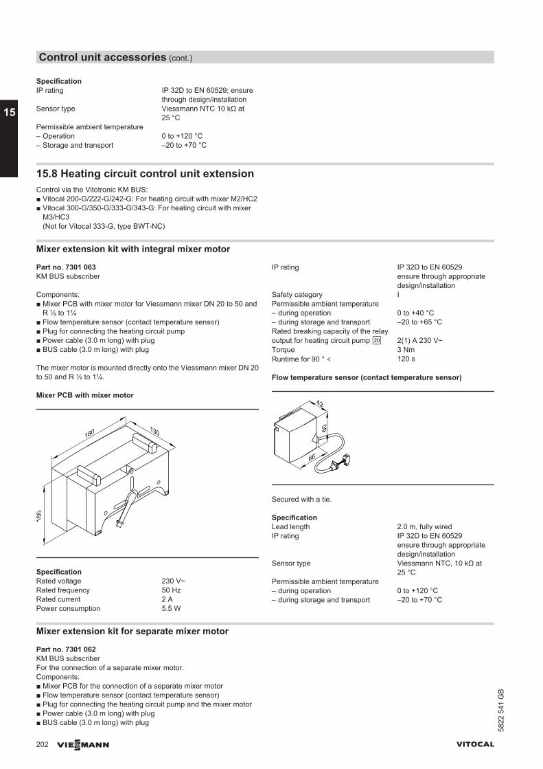
SpecificationIP rating IP 32D to EN 60529; ensure
through design/installationSensor type Viessmann NTC 10 kΩ at
25 °CPermissible ambient temperature – Operation 0 to +120 °C– Storage and transport –20 to +70 °C
15.8 Heating circuit control unit extensionControl via the Vitotronic KM BUS:■ Vitocal 200-G/222-G/242-G: For heating circuit with mixer M2/HC2■ Vitocal 300-G/350-G/333-G/343-G: For heating circuit with mixer
M3/HC3(Not for Vitocal 333-G, type BWT-NC)
Mixer extension kit with integral mixer motor
Part no. 7301 063KM BUS subscriber
Components:■ Mixer PCB with mixer motor for Viessmann mixer DN 20 to 50 and
R ½ to 1¼■ Flow temperature sensor (contact temperature sensor)■ Plug for connecting the heating circuit pump■ Power cable (3.0 m long) with plug■ BUS cable (3.0 m long) with plug
The mixer motor is mounted directly onto the Viessmann mixer DN 20to 50 and R ½ to 1¼.
Mixer PCB with mixer motor
160
180 130
SpecificationRated voltage 230 V~Rated frequency 50 HzRated current 2 APower consumption 5.5 W
IP rating IP 32D to EN 60529ensure through appropriatedesign/installation
Safety category IPermissible ambient temperature – during operation 0 to +40 °C– during storage and transport –20 to +65 °CRated breaking capacity of the relayoutput for heating circuit pump sÖ 2(1) A 230 V~Torque 3 NmRuntime for 90 ° ∢ 120 s
Flow temperature sensor (contact temperature sensor)
42
66
60
Secured with a tie.
SpecificationLead length 2.0 m, fully wiredIP rating IP 32D to EN 60529
ensure through appropriatedesign/installation
Sensor type Viessmann NTC, 10 kΩ at25 °C
Permissible ambient temperature – during operation 0 to +120 °C– during storage and transport –20 to +70 °C
Mixer extension kit for separate mixer motor
Part no. 7301 062KM BUS subscriberFor the connection of a separate mixer motor.Components:■ Mixer PCB for the connection of a separate mixer motor■ Flow temperature sensor (contact temperature sensor)■ Plug for connecting the heating circuit pump and the mixer motor■ Power cable (3.0 m long) with plug■ BUS cable (3.0 m long) with plug
Control unit accessories (cont.)
202 VIESMANN VITOCAL
15
5822
541
GB
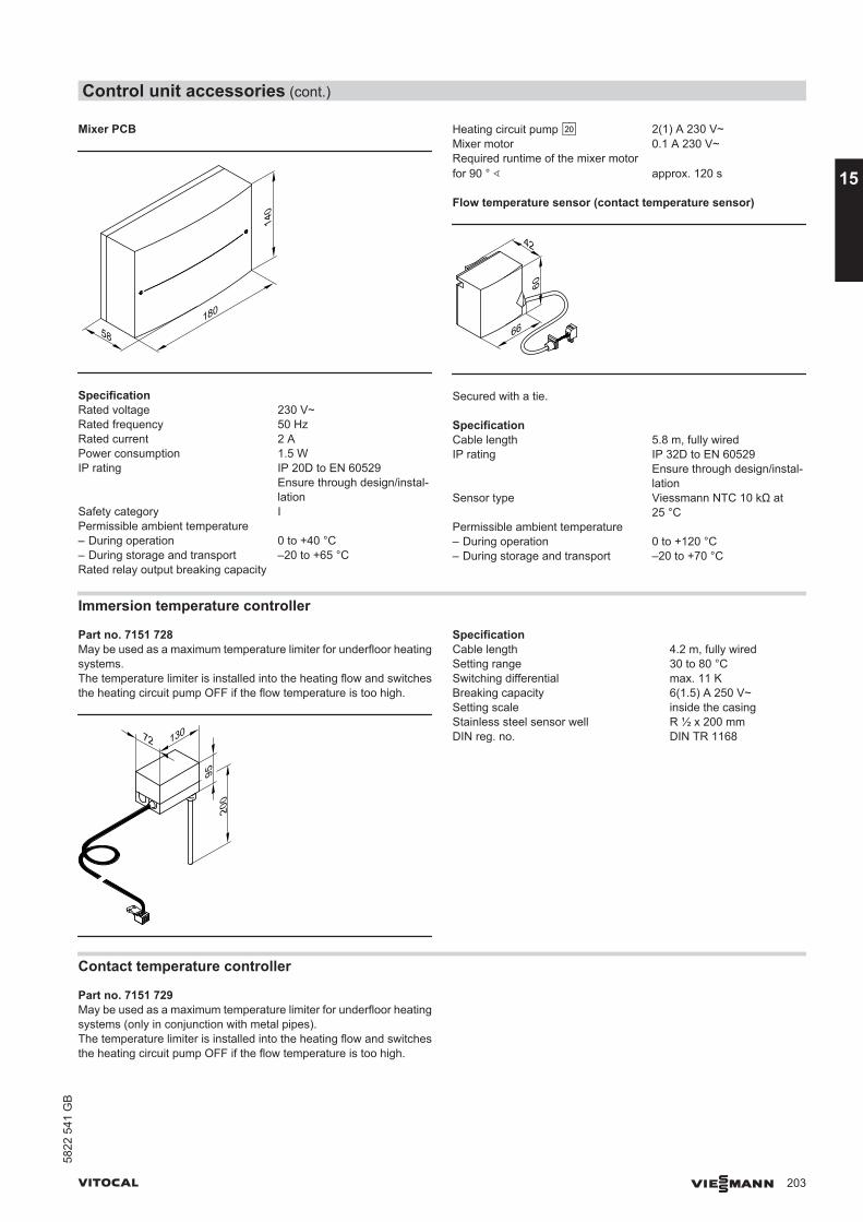
Mixer PCB
58180
140
SpecificationRated voltage 230 V~Rated frequency 50 HzRated current 2 APower consumption 1.5 WIP rating IP 20D to EN 60529
Ensure through design/instal-lation
Safety category IPermissible ambient temperature – During operation 0 to +40 °C– During storage and transport –20 to +65 °CRated relay output breaking capacity
Heating circuit pump sÖ 2(1) A 230 V~Mixer motor 0.1 A 230 V~Required runtime of the mixer motorfor 90 ° ∢ approx. 120 s
Flow temperature sensor (contact temperature sensor)
42
66
60
Secured with a tie.
SpecificationCable length 5.8 m, fully wiredIP rating IP 32D to EN 60529
Ensure through design/instal-lation
Sensor type Viessmann NTC 10 kΩ at25 °C
Permissible ambient temperature – During operation 0 to +120 °C– During storage and transport –20 to +70 °C
Immersion temperature controller
Part no. 7151 728May be used as a maximum temperature limiter for underfloor heatingsystems.The temperature limiter is installed into the heating flow and switchesthe heating circuit pump OFF if the flow temperature is too high.
72 130
9520
0
SpecificationCable length 4.2 m, fully wiredSetting range 30 to 80 °CSwitching differential max. 11 KBreaking capacity 6(1.5) A 250 V~Setting scale inside the casingStainless steel sensor well R ½ x 200 mmDIN reg. no. DIN TR 1168
Contact temperature controller
Part no. 7151 729May be used as a maximum temperature limiter for underfloor heatingsystems (only in conjunction with metal pipes).The temperature limiter is installed into the heating flow and switchesthe heating circuit pump OFF if the flow temperature is too high.
Control unit accessories (cont.)
VITOCAL VIESMANN 203
5822
541
GB
15
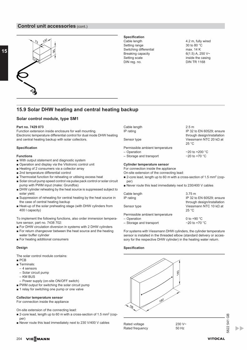
72 130
95
SpecificationCable length 4.2 m, fully wiredSetting range 30 to 80 °CSwitching differential max. 14 KBreaking capacity 6(1.5) A, 250 V~Setting scale inside the casingDIN reg. no. DIN TR 1168
15.9 Solar DHW heating and central heating backup
Solar control module, type SM1
Part no. 7429 073Function extension inside enclosure for wall mounting.Electronic temperature differential control for dual mode DHW heatingand central heating backup with solar collectors.
Specification
Functions■ With output statement and diagnostic system■ Operation and display via the Vitotronic control unit■ Heating of 2 consumers via a collector array■ 2nd temperature differential control■ Thermostat function for reheating or utilising excess heat■ Solar circuit pump speed control via pulse pack control or solar circuit
pump with PWM input (make: Grundfos)■ DHW cylinder reheating by the heat source is suppressed subject to
solar yield.■ Suppression of reheating for central heating by the heat source in
the case of central heating backup■ Heat-up of the solar preheating stage (with DHW cylinders from
400 l capacity)
To implement the following functions, also order immersion tempera-ture sensor, part no. 7438 702:■ For DHW circulation diversion in systems with 2 DHW cylinders■ For return changeover between the heat source and the heating
water buffer cylinder■ For heating additional consumers
Design
The solar control module contains:■ PCB■ Terminals:
– 4 sensors– Solar circuit pump– KM BUS– Power supply (on-site ON/OFF switch)
■ PWM output for switching the solar circuit pump■ 1 relay for switching one pump or one valve
Collector temperature sensorFor connection inside the appliance
On-site extension of the connecting lead:■ 2-core lead, length up to 60 m with a cross-section of 1.5 mm2 (cop-
per)■ Never route this lead immediately next to 230 V/400 V cables
Cable length 2.5 mIP rating IP 32 to EN 60529; ensure
through design/installationSensor type Viessmann NTC 20 kΩ at
25 °CPermissible ambient temperature– Operation −20 to +200 °C– Storage and transport −20 to +70 °C
Cylinder temperature sensorFor connection inside the applianceOn-site extension of the connecting lead:■ 2-core lead, length up to 60 m with a cross-section of 1.5 mm2 (cop-
per)■ Never route this lead immediately next to 230/400 V cables
Cable length 3.75 mIP rating IP 32 to EN 60529; ensure
through design/installationSensor type Viessmann NTC 10 kΩ at
25 °CPermissible ambient temperature– Operation 0 to +90 °C– Storage and transport −20 to +70 °C
For systems with Viessmann DHW cylinders, the cylinder temperaturesensor is installed in the threaded elbow (standard delivery or acces-sory for the respective DHW cylinder) in the heating water return.
Specification
58180
140
Rated voltage 230 V~Rated frequency 50 Hz
Control unit accessories (cont.)
204 VIESMANN VITOCAL
15
5822
541
GB
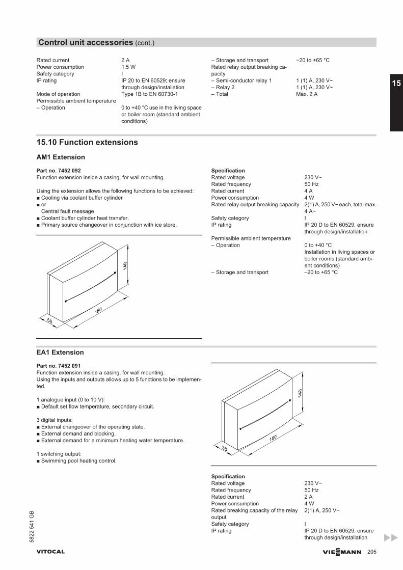
Rated current 2 APower consumption 1.5 WSafety category IIP rating IP 20 to EN 60529; ensure
through design/installationMode of operation Type 1B to EN 60730-1Permissible ambient temperature – Operation 0 to +40 °C use in the living space
or boiler room (standard ambientconditions)
– Storage and transport −20 to +65 °CRated relay output breaking ca-pacity
– Semi-conductor relay 1 1 (1) A, 230 V~– Relay 2 1 (1) A, 230 V~– Total Max. 2 A
15.10 Function extensions
AM1 Extension
Part no. 7452 092Function extension inside a casing, for wall mounting.
Using the extension allows the following functions to be achieved:■ Cooling via coolant buffer cylinder■ or
Central fault message■ Coolant buffer cylinder heat transfer.■ Primary source changeover in conjunction with ice store.
58180
140
SpecificationRated voltage 230 V~Rated frequency 50 HzRated current 4 APower consumption 4 WRated relay output breaking capacity 2(1) A, 250 V~ each, total max.
4 A~Safety category IIP rating IP 20 D to EN 60529, ensure
through design/installationPermissible ambient temperature – Operation 0 to +40 °C
Installation in living spaces orboiler rooms (standard ambi-ent conditions)
– Storage and transport –20 to +65 °C
EA1 Extension
Part no. 7452 091Function extension inside a casing, for wall mounting.Using the inputs and outputs allows up to 5 functions to be implemen-ted.
1 analogue input (0 to 10 V):■ Default set flow temperature, secondary circuit.
3 digital inputs:■ External changeover of the operating state.■ External demand and blocking.■ External demand for a minimum heating water temperature.
1 switching output:■ Swimming pool heating control.
58180
140
SpecificationRated voltage 230 V~Rated frequency 50 HzRated current 2 APower consumption 4 WRated breaking capacity of the relayoutput
2(1) A, 250 V~
Safety category IIP rating IP 20 D to EN 60529, ensure
through design/installation
Control unit accessories (cont.)
VITOCAL VIESMANN 205
5822
541
GB
15
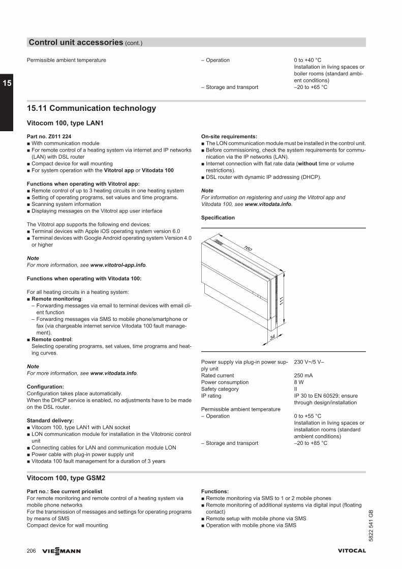
Permissible ambient temperature – Operation 0 to +40 °CInstallation in living spaces orboiler rooms (standard ambi-ent conditions)
– Storage and transport –20 to +65 °C
15.11 Communication technology
Vitocom 100, type LAN1
Part no. Z011 224■ With communication module■ For remote control of a heating system via internet and IP networks
(LAN) with DSL router■ Compact device for wall mounting■ For system operation with the Vitotrol app or Vitodata 100
Functions when operating with Vitotrol app:■ Remote control of up to 3 heating circuits in one heating system■ Setting of operating programs, set values and time programs.■ Scanning system information■ Displaying messages on the Vitotrol app user interface
The Vitotrol app supports the following end devices:■ Terminal devices with Apple iOS operating system version 6.0■ Terminal devices with Google Android operating system Version 4.0
or higher
NoteFor more information, see www.vitotrol-app.info.
Functions when operating with Vitodata 100:
For all heating circuits in a heating system:■ Remote monitoring:
– Forwarding messages via email to terminal devices with email cli-ent function
– Forwarding messages via SMS to mobile phone/smartphone orfax (via chargeable internet service Vitodata 100 fault manage-ment).
■ Remote control:Selecting operating programs, set values, time programs and heat-ing curves.
NoteFor more information, see www.vitodata.info.
Configuration:Configuration takes place automatically.When the DHCP service is enabled, no adjustments have to be madeon the DSL router.
Standard delivery:■ Vitocom 100, type LAN1 with LAN socket■ LON communication module for installation in the Vitotronic control
unit■ Connecting cables for LAN and communication module LON■ Power cable with plug-in power supply unit■ Vitodata 100 fault management for a duration of 3 years
On-site requirements:■ The LON communication module must be installed in the control unit.■ Before commissioning, check the system requirements for commu-
nication via the IP networks (LAN).■ Internet connection with flat rate data (without time or volume
restrictions).■ DSL router with dynamic IP addressing (DHCP).
NoteFor information on registering and using the Vitotrol app andVitodata 100, see www.vitodata.info.
Specification
160
34
111
Power supply via plug-in power sup-ply unit
230 V~/5 V–
Rated current 250 mAPower consumption 8 WSafety category IIIP rating IP 30 to EN 60529; ensure
through design/installationPermissible ambient temperature – Operation 0 to +55 °C
Installation in living spaces orinstallation rooms (standardambient conditions)
– Storage and transport –20 to +85 °C
Vitocom 100, type GSM2
Part no.: See current pricelistFor remote monitoring and remote control of a heating system viamobile phone networksFor the transmission of messages and settings for operating programsby means of SMSCompact device for wall mounting
Functions:■ Remote monitoring via SMS to 1 or 2 mobile phones■ Remote monitoring of additional systems via digital input (floating
contact)■ Remote setup with mobile phone via SMS■ Operation with mobile phone via SMS
Control unit accessories (cont.)
206 VIESMANN VITOCAL
15
5822
541
GB
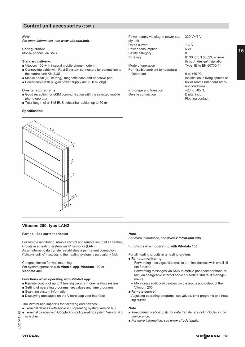
NoteFor more information, see www.vitocom.info.
Configuration:Mobile phones via SMS
Standard delivery:■ Vitocom 100 with integral mobile phone modem■ Connecting cable with Rast 5 system connectors for connection to
the control unit KM BUS■ Mobile aerial (3.0 m long), magnetic base and adhesive pad■ Power cable with plug-in power supply unit (2.0 m long)
On-site requirements:■ Good reception for GSM communication with the selected mobile
phone operator■ Total length of all KM BUS subscriber cables up to 50 m
Specification
26.5
160
111
34
Power supply via plug-in power sup-ply unit
230 V~/5 V–
Rated current 1.6 APower consumption 5 WSafety category IIIP rating IP 30 to EN 60529; ensure
through design/installationMode of operation Type 1B to EN 60730-1Permissible ambient temperature – Operation 0 to +50 °C
Installation in living spaces orboiler rooms (standard ambi-ent conditions)
– Storage and transport –20 to +85 °COn-site connection Digital input:
Floating contact
Vitocom 200, type LAN2
Part no.: See current pricelist
For remote monitoring, remote control and remote setup of all heatingcircuits in a heating system via IP networks (LAN)As an internet data transfer establishes a permanent connection("always online"), access to the heating system is particularly fast.
Compact device for wall mountingFor system operation with Vitotrol app, Vitodata 100 orVitodata 300
Functions when operating with Vitotrol app:■ Remote control of up to 3 heating circuits in one heating system■ Setting of operating programs, set values and time programs■ Scanning system information■ Displaying messages on the Vitotrol app user interface
The Vitotrol app supports the following end devices:■ Terminal devices with Apple iOS operating system version 6.0■ Terminal devices with Google Android operating system Version 4.0
or higher
NoteFor more information, see www.vitotrol-app.info.
Functions when operating with Vitodata 100:
For all heating circuits in a heating system:■ Remote monitoring:
– Forwarding messages via email to terminal devices with email cli-ent function
– Forwarding messages via SMS to mobile phone/smartphone orfax (via chargeable internet service Vitodata 100 fault manage-ment)
– Monitoring additional devices via the inputs and output of theVitocom 200
■ Remote control:Adjusting operating programs, set values, time programs and heat-ing curves
Note■ Telecommunication costs for data transfer are not included in the
device price.■ For more information, see www.vitodata.info.
Control unit accessories (cont.)
VITOCAL VIESMANN 207
5822
541
GB
15
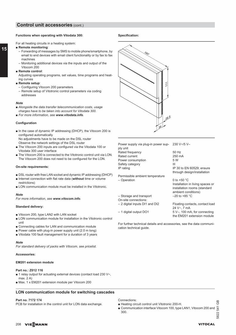
Functions when operating with Vitodata 300:
For all heating circuits in a heating system:■ Remote monitoring:
– Forwarding of messages by SMS to mobile phone/smartphone, byemail to end devices with email client functionality or by fax to faxmachines
– Monitoring additional devices via the inputs and output of theVitocom 200
■ Remote control:Adjusting operating programs, set values, time programs and heat-ing curves
■ Remote setup:– Configuring Vitocom 200 parameters– Remote setup of Vitotronic control parameters via coding
addresses
Note■ Alongside the data transfer telecommunication costs, usage
charges have to be taken into account for Vitodata 300.■ For more information, see www.vitodata.info.
Configuration
■ In the case of dynamic IP addressing (DHCP), the Vitocom 200 isconfigured automaticallyNo adjustments have to be made on the DSL routerObserve the network settings of the DSL router
■ The Vitocom 200 inputs are configured via the Vitodata 100 orVitodata 300 user interface
■ The Vitocom 200 is connected to the Vitotronic control unit via LON.The Vitocom 200 does not need to be configured for the LON.
On-site requirements:
■ DSL router with free LAN socket and dynamic IP addressing (DHCP)■ Internet connection with flat rate data (without time or volume
restrictions)■ LON communication module must be installed in the Vitotronic.
NoteFor more information, see www.vitocom.info.
Standard delivery:
■ Vitocom 200, type LAN2 with LAN socket■ LON communication module for installation in the Vitotronic control
unit■ Connecting cables for LAN and communication module■ Power cable with plug-in power supply unit (2.0 m long)■ Vitodata 100 fault management for a duration of 3 years
NoteFor standard delivery of packs with Vitocom, see pricelist.
Accessories:
EM201 extension module
Part no.: Z012 116■ 1 relay output for actuating external devices (contact load 230 V~,
max. 2 A)■ Max. 1 x EM201 extension module per Vitocom 200
Specification:
26.5
160
111
34
Power supply via plug-in power sup-ply unit
230 V~/5 V–
Rated frequency 50 HzRated current 250 mAPower consumption 5 WSafety category IIIIP rating IP 30 to EN 60529; ensure
through design/installationPermissible ambient temperature – Operation 0 to +50 °C
Installation in living spaces orinstallation rooms (standardambient conditions)
– Storage and transport –20 to +85 °COn-site connections: – 2 digital inputs DI1 and DI2 Floating contacts, contact load
24 V−, 7 mA– 1 digital output DO1 5 V–, 100 mA, for connecting
the EM201 extension module
For further technical details and accessories, see the data communi-cation technical guide.
LON communication module for switching cascades
Part no. 7172 174PCB for installation in the control unit for LON data exchange.
Connections:■ Heating circuit control unit Vitotronic 200-H.■ Communication interface Vitocom 100, type LAN1, Vitocom 200 and
300.
Control unit accessories (cont.)
208 VIESMANN VITOCAL
15
5822
541
GB
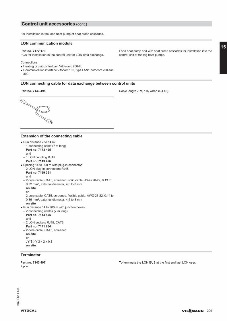
For installation in the lead heat pump of heat pump cascades.
LON communication module
Part no. 7172 173PCB for installation in the control unit for LON data exchange.
Connections:■ Heating circuit control unit Vitotronic 200-H.■ Communication interface Vitocom 100, type LAN1, Vitocom 200 and
300.
For a heat pump and with heat pump cascades for installation into thecontrol unit of the lag heat pumps.
LON connecting cable for data exchange between control units
Part no. 7143 495 Cable length 7 m, fully wired (RJ 45).
Extension of the connecting cable■ Run distance 7 to 14 m:
– 1 connecting cable (7 m long)Part no. 7143 495and
– 1 LON coupling RJ45Part no. 7143 496
■ Spacing 14 to 900 m with plug-in connector:– 2 LON plug-in connectors RJ45
Part no. 7199 251and
– 2-core cable, CAT5, screened, solid cable, AWG 26-22, 0.13 to0.32 mm2, external diameter, 4.5 to 8 mmon siteor2-core cable, CAT5, screened, flexible cable, AWG 26-22, 0.14 to0.36 mm2, external diameter, 4.5 to 8 mmon site
■ Run distance 14 to 900 m with junction boxes:– 2 connecting cables (7 m long)
Part no. 7143 495and
– 2 LON sockets RJ45, CAT6Part no. 7171 784
– 2-core cable, CAT5, screenedon siteorJY(St) Y 2 x 2 x 0.8on site
Terminator
Part no. 7143 4972 pce
To terminate the LON BUS at the first and last LON user.
Control unit accessories (cont.)
VITOCAL VIESMANN 209
5822
541
GB
15
AAC-Box...................................................................................133, 183AC-Box, connection accessories...................................................134Active cooling.................................................................133, 180, 182Air separator...................................................................................118Air vent unit....................................................................................125AM1 Extension...............................................................................205Anti-seizing pump protection..........................................................188Aperture area.................................................................................137Application limits– 200-G............................................................................................11– 222-G............................................................................................69– 242-G............................................................................................82– 300-G......................................................................................27, 43– 333-G............................................................................................95– 343-G..........................................................................................104– 350-G......................................................................................55, 62Application procedure (details).......................................................140Auxiliary function............................................................................188
BBrine manifold................................................................................121Bypass...........................................................................................115
CCasing panels................................................................................131Central heating/central cooling.......................................................170Circulation pump for cylinder loading.............................................130Collector circuit...............................................................................137Collector temperature sensor.................................................139, 200Communication module LON.........................................................155Connection on the DHW side.........................................................173Connection set, DHW.....................................................................128Connection set, DHW circulation...................................................129Connection set, heating circuit flow/heating circuit return..............128Connection set, primary/secondary circuit.....................................127Connections on the primary side (brine-water)– 2-stage heat pumps....................................................................150– Single stage heat pump..............................................................148Contact temperature controller.......................................................203Contact temperature sensor...................................................135, 199Coolant...........................................................................................169Cooling circuit.................................................................................171Cooling curve.................................................................................188– Level...........................................................................................190– Slope...........................................................................................190Cooling function.............................................................................171– Active cooling..............................................................................182– Natural cooling............................................................................180Cooling limit....................................................................................188Cooling mode.................................................................................180– Weather-compensated control....................................................171Cooling operation...........................................................................171– Types and configuration..............................................................180Cooling with an underfloor heating system....................................181Cooling with fan convectors...........................................................182
DDelivered condition– Vitocal 200-G..................................................................................7– Vitocal 222-G................................................................................64– Vitocal 242-G................................................................................76– Vitocal 300-G....................................................................20, 38, 48– Vitocal 333-G..........................................................................89, 90– Vitocal 343-G..............................................................................100– Vitocal 350-G..........................................................................47, 58DHW circulation connection set.....................................................129DHW connection set......................................................................128DHW cylinder.................................................................................173DHW cylinders...............................................................................108DHW demand.................................................................................158DHW heating..................................................................................186– Connection on the DHW side......................................................173– Selecting a cylinder loading system............................................178– Selecting a plate heat exchanger................................................178– Selection of a DHW cylinder.......................................................175DHW temperature..........................................................................188Diagnostic system..........................................................................188Dimensions– Vitocal 200-G................................................................................10– Vitocal 222-G................................................................................68– Vitocal 242-G................................................................................81– Vitocal 300-G....................................................................25, 26, 42– Vitocal 333-G................................................................................94– Vitocal 343-G..............................................................................103– Vitocal 350-G..........................................................................53, 61Diverter valve.................................................................................134Double U-shaped pipe probe.........................................................163Drain outlet kit................................................................................131
EEA1 Extension................................................................................205Economy mode..............................................................................188EHE immersion heater...................................................................130Electrical connections....................................................................144Electrical demand...........................................................................140Electricity meter..............................................................................144Electric preheater coil.....................................................................115EnEV..............................................................................................190Ethylene glycol...............................................................................159Exhaust air.....................................................................................116Expansion vessel– Primary circuit.............................................................................165– Solar............................................................................................187– Solar expansion vessel...............................................................186– Structure, function, specification.................................................187– Volume calculation......................................................................187Extended menu..............................................................................188Extension kit for mixer– Separate mixer motor.................................................................202External demand............................................................................188External heat generator..................................................................158External hook-up............................................................................188Extract air.......................................................................................116
Keyword index
210 VIESMANN VITOCAL
5822
541
GB
FFan convectors.......................................................................135, 182Fault...............................................................................................188Federal tariffs [Germany]...............................................................140Fill water.........................................................................................172Filter change indicator....................................................................115Filters for ventilation unit................................................................115Flanged aperture............................................................................130Flange hood...................................................................................130Flow rate........................................................................................168Flow rate control.............................................................................115Flow temperature...................................................................188, 189Frost protection......................................................................159, 188Frost protection function.................................................................190Function description– DHW heating...............................................................................173– Heating circuit.............................................................................170– Instantaneous heating water heater............................................158
GGeothermal collector– Manifolds and headers................................................................159– Sizing..........................................................................................162Geothermal probe– Pressure drop.............................................................................165– Sizing..........................................................................................165Groundwater..................................................................................167
HHeat exchanger, primary circuit.....................................................169Heating circuit and heat distribution...............................................170Heating curve.................................................................................188– Level...........................................................................................190– Slope...........................................................................................190Heating lance.........................................................................130, 176Heating limit...................................................................................188Heating output................................................................................157Heating water buffer cylinder.........................................................171Heating water flow temperature.....................................................170Heat load........................................................................................157Heat pump cascade.......................................................................155Heat pump control unit– Design.........................................................................................188– Functions....................................................................................188– Languages..................................................................................188– PCBs...........................................................................................188– Programming unit........................................................................188– Standard modules.......................................................................188Heat pump sizing...........................................................................157Heat recovery.................................................................................115Heat recovery level........................................................................116Heat transfer medium.............................................................123, 167Help text.........................................................................................188Holiday program.............................................................................188Hook-up..........................................................................................188Hydraulic connection– Cylinder loading system..............................................................176– DHW cylinder..............................................................................174Hydraulic connections....................................................................148Hydraulic modules– Single stage heat pumps............................................................123– Two-stage heat pumps...............................................................124
IImmersion heater...........................................................................129Immersion temperature controller..................................................203Impressed current anode.......................................................129, 131Information.....................................................................................188Installation accessories– Primary circuit.............................................................................117– Secondary circuit................................................................112, 123Instantaneous heating water heater.......................................126, 158Integral solar control function.................................................186, 189Intended use..................................................................................187
KKM BUS distributor.........................................................................200
LLag heat pump...............................................................................155LON........................................................................................208, 209LON communication module..........................................................209– For switching cascades...............................................................208LON module...................................................................................155
MMechanical ventilation unit.............................................................115Minimum clearances......................................................................140Minimum room height.....................................................................142Mixer extension– Integral mixer motor....................................................................202– Separate mixer motor.................................................................202Mixer extension kit– Integral mixer motor....................................................................202Mono energetic operation..............................................................157Mono mode operation....................................................................157Motorised ball valve...............................................................130, 135
NNatural cooling.......................................................................132, 180Navigation......................................................................................188NC-Box...................................................................................132, 180
OOperating mode– Dual mode...................................................................................158Operating program.........................................................................188Operating status.............................................................................188Operation– Mono energetic...........................................................................157– Mono mode.................................................................................157Outdoor air.....................................................................................116Output diagrams– Vitocal 200-G..........................................................................12, 17– Vitocal 222-G................................................................................70– Vitocal 242-G................................................................................83– Vitocal 300-G..........................................................................28, 44– Vitocal 333-G................................................................................96– Vitocal 343-G..............................................................................105– Vitocal 350-G..........................................................................56, 63Output matching, fan convectors...................................................182Outside temperature sensor...........................................................191Oversizing......................................................................................157
Keyword index
VITOCAL VIESMANN 211
5822
541
GB
PParty mode.....................................................................................188Plain text display............................................................................188Platform for unfinished floors.........................................................131Potable water softening system.....................................................172Power cable...................................................................................147Power-OFF.....................................................................140, 144, 157Power-OFF period..........................................................................140Power-OFF time.............................................................................157Power supply..........................................................................140, 147Power tariffs...................................................................................140Preheater coil.................................................................................115Pressure drop– Vitocal 300-G..........................................................................28, 44– Vitocal 350-G..........................................................................56, 63Pressure drop in pipes...................................................................166Primary pump.................................................................................119Primary source– Brine............................................................................................159– Groundwater/coolant...................................................................167Product information– Vitocal 200-G..................................................................................7– Vitocal 222-G................................................................................64– Vitocal 242-G................................................................................76– Vitocal 300-G..........................................................................20, 38– Vitocal 333-G................................................................................89– Vitocal 343-G................................................................................99– Vitocal 350-G................................................................................47Pump output supplements.............................................................167
RRequired equipment.......................................................................148Residual heads– Vitocal 200-G..........................................................................12, 17– Vitocal 222-G................................................................................70– Vitocal 242-G................................................................................83– Vitocal 300-G................................................................................33– Vitocal 333-G................................................................................96– Vitocal 343-G..............................................................................105– Vitocal 350-G................................................................................57Return well.....................................................................................168Room temperature.........................................................................188Room temperature sensor.............................................................199Room temperature sensor for cooling circuit.................................135Room temperature sensor for cooling operation....................180, 183
SSafety equipment block..................................................................127Safety valve....................................................................................174Screed drying.................................................................................188Seasonal performance factor.........................................................170Secondary side connections (2-stage heat pumps).......................153Settings..........................................................................................188Siting..............................................................................................140Sizing the heat pump.....................................................................157Solar central heating backup..........................................................186Solar circuit pump..........................................................................137Solar collectors...............................................................................186Solar control module......................................................186, 189, 204– Specification................................................................................204Solar DHW heating........................................................................186Solar-Divicon..................................................................................137Solar expansion vessel..................................................................187Solar internal indirect coil set.........................................................129Solar swimming pool heating.........................................................186Solar thermal system.....................................................................186Specification– Solar control module...................................................................204– Ventilation unit............................................................................116– Vitocal 300-G........................................................22, 39, 40, 59, 60– Vitocal 333-G................................................................................91– Vitocal 343-G..............................................................................101– Vitocal 350-G................................................................................49Standard delivery– Vitocal 200-G..................................................................................7– Vitocal 222-G................................................................................64– Vitocal 242-G................................................................................76– Vitocal 300-G....................................................................20, 38, 48– Vitocal 333-G................................................................................89– Vitocal 343-G..............................................................................100– Vitocal 350-G..........................................................................47, 58Standard heat load of the building.................................................157Summer bypass.............................................................................115Supplement for DHW heating........................................................158Supplement for setback mode.......................................................159Supply air.......................................................................................116Supply well.....................................................................................168System separation.........................................................................168
TTechnical connection requirements...............................................144Temperature controller– Contact temperature...................................................................203– Immersion temperature...............................................................203Temperature limit...........................................................................188Temperature sensor– Contact temperature sensor...............................................135, 199– Outside temperature sensor.......................................................191– Room temperature sensor..........................................................199– Wireless outside temperature sensor.........................................198Time program.................................................................................188Time switch....................................................................................190Top-up water..................................................................................172Transport aid..................................................................................132Tyfocor...........................................................................................167
UUnderfloor heating..........................................................................181
Keyword index
212 VIESMANN VITOCAL
5822
541
GB
VVentilation......................................................................................115Ventilation unit................................................................................115– Specification................................................................................116Vitocom– 100, type GSM............................................................................206– 100, type LAN1...........................................................................206Vitotrol– 200A............................................................................................194– 200 RF........................................................................................195– 300B............................................................................................194– 300 RF B with table-top dock......................................................197– 300 RF B with wall mounting bracket..........................................196Vitovent 300-F................................................................................115Volumes in pipes............................................................................167
WWall clearances..............................................................................140Warning..........................................................................................188Water quality..................................................................................172Weather-compensated control...............................................171, 189Weather-compensated control unit– Frost protection function.............................................................190– Operating programs....................................................................190Wireless components– Wireless base station B..............................................................197– Wireless outside temperature sensor.........................................198– Wireless remote control..............................................195, 196, 197– Wireless repeater........................................................................198
Keyword index
VITOCAL VIESMANN 213
5822
541
GB

214 VIESMANN VITOCAL

VITOCAL VIESMANN 215
5822
541
GB

216 VIESMANN VITOCAL
5822
541
GB
Subject to technical modifications.
Viessmann LimitedHortonwood 30, TelfordShropshire, TF1 7YP, GBTelephone: +44 1952 675000Fax: +44 1952 675040E-mail: [email protected]
Viessmann Werke GmbH&Co KGD-35107 AllendorfTelephone: +49 6452 70-0Fax: +49 6452 70-2780www.viessmann.com