VIDEO CASSETTE RECORDER HR-S5400U - JVCresources.jvc.com/Resources/00/00/99/LPT0002-016B.pdf ·...
72
HR-S5400U VIDEO CASSETTE RECORDER INSTRUCTIONS LPT0002-016B For Customer Use: Enter below the Model No. and Serial No. which are located on the rear of cabinet. Retain this information for future reference. Model No. Serial No. INSERT PAUSE REC STOP/EJECT PLAY q POWER JOG SHUTTLE VIDEO (MONO)L – AUDIO – R SP/EP LIVE SURROUND MENU CH OK A. DUB REW FF H M S SP AM PM REC PLAY SAP ST TIMER PAUSE M VCR +8 4 0 6 10 –20dB NORM L R A/B TV CABLE/DBS TV, CABLE / DBS operation – Press and hold TV CABLE/DBS button, then press POWER, CH 5/∞, TV/VCR, 0 – 9, ENTER TV/VCR 1 2 3 4 5 6 7 8DAILY 0AUX 9WEEKLY LIVE SURROUND MBR SET DISPLAY TIMER CANCEL C.MEMORY SKIP SEARCH C.RESET/CH.SKIP ADD OSD ENTER SP/EP TV VOL CH MENU SHUTTLE PLUS OK ¶REC 4 ¢ 7STOP 8PAUSE POWER 3PLAY 1 FF ¡ REW
Transcript of VIDEO CASSETTE RECORDER HR-S5400U - JVCresources.jvc.com/Resources/00/00/99/LPT0002-016B.pdf ·...
HR-S5400UVIDEO CASSETTE RECORDER
INSTRUCTIONS
LPT0002-016B
For Customer Use: Enter below the Model No. and Serial No. which are located on the rear of cabinet. Retain this information for future reference. Model No. Serial No.
INSERT
PAUSE
REC
STOP/EJECT PLAY
q
POWER
JOG
SHUTTLE
VIDEO (MONO)L – AUDIO – R
SP/EP
LIVE SURROUNDMENU CH OK
A. DUB
REW FF
H M S
SP AM
PM
R E CPLAY
SAP ST
TIMERPAUSE
M
V C R+840
610
–20dBNORML R
A/BTV CABLE/DBS
TV, CABLE / DBS operation – Press and hold TV CABLE/DBS button, then press POWER, CH 5/∞, TV/VCR, 0 – 9, ENTER
TV/VCR 1 2 3
4 5 6
7 8 DAILY
0 AUX
9 WEEKLY
LIVE SURROUND
MBR SET DISPLAY
TIMER
CANCEL C.MEMORY
SKIP SEARCHC.RESET/CH.SKIP ADD
OSD
ENTER SP/EP
TV VOL CH
MENU
SHUTTLE PLUS
OK
¶REC
4 ¢
7STOP 8PAUSE
POWER
3PLAY1 FF ¡REW
2 EN
Dear Customer,Thank you for purchasing the JVC VHS video cassette recorder. Before use, please read the safety information and precautionscontained in the following pages to ensure safe use of your new VCR.
CAUTIONS
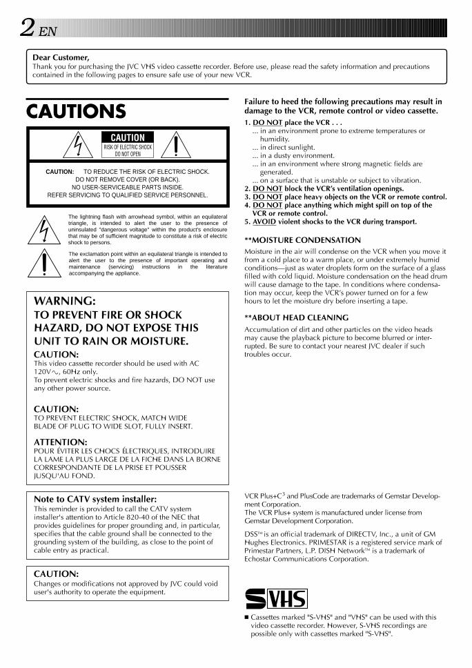
WARNING:TO PREVENT FIRE OR SHOCKHAZARD, DO NOT EXPOSE THISUNIT TO RAIN OR MOISTURE.CAUTION:This video cassette recorder should be used with AC120V`, 60Hz only.To prevent electric shocks and fire hazards, DO NOT useany other power source.
CAUTION:TO PREVENT ELECTRIC SHOCK, MATCH WIDEBLADE OF PLUG TO WIDE SLOT, FULLY INSERT.
ATTENTION:POUR ÉVITER LES CHOCS ÉLECTRIQUES, INTRODUIRELA LAME LA PLUS LARGE DE LA FICHE DANS LA BORNECORRESPONDANTE DE LA PRISE ET POUSSERJUSQU'AU FOND.
CAUTION RISK OF ELECTRIC SHOCK
DO NOT OPEN
CAUTION: TO REDUCE THE RISK OF ELECTRIC SHOCK. DO NOT REMOVE COVER (OR BACK).
NO USER-SERVICEABLE PARTS INSIDE. REFER SERVICING TO QUALIFIED SERVICE PERSONNEL.
The lightning flash with arrowhead symbol, within an equilateral triangle, is intended to alert the user to the presence of uninsulated "dangerous voltage" within the product's enclosure that may be of sufficient magnitude to constitute a risk of electric shock to persons.
The exclamation point within an equilateral triangle is intended to alert the user to the presence of important operating and maintenance (servicing) instructions in the literature accompanying the appliance.
Failure to heed the following precautions may result indamage to the VCR, remote control or video cassette.1. DO NOT place the VCR . . .
... in an environment prone to extreme temperatures orhumidity.
... in direct sunlight.
... in a dusty environment.
... in an environment where strong magnetic fields aregenerated.
... on a surface that is unstable or subject to vibration.2. DO NOT block the VCR’s ventilation openings.3. DO NOT place heavy objects on the VCR or remote control.4. DO NOT place anything which might spill on top of the
VCR or remote control.5. AVOID violent shocks to the VCR during transport.
**MOISTURE CONDENSATIONMoisture in the air will condense on the VCR when you move itfrom a cold place to a warm place, or under extremely humidconditions—just as water droplets form on the surface of a glassfilled with cold liquid. Moisture condensation on the head drumwill cause damage to the tape. In conditions where condensa-tion may occur, keep the VCR’s power turned on for a fewhours to let the moisture dry before inserting a tape.
**ABOUT HEAD CLEANINGAccumulation of dirt and other particles on the video headsmay cause the playback picture to become blurred or inter-rupted. Be sure to contact your nearest JVC dealer if suchtroubles occur.
Note to CATV system installer:This reminder is provided to call the CATV systeminstaller's attention to Article 820-40 of the NEC thatprovides guidelines for proper grounding and, in particular,specifies that the cable ground shall be connected to thegrounding system of the building, as close to the point ofcable entry as practical.
CAUTION:Changes or modifications not approved by JVC could voiduser's authority to operate the equipment.
n Cassettes marked "S-VHS" and "VHS" can be used with thisvideo cassette recorder. However, S-VHS recordings arepossible only with cassettes marked "S-VHS".
VCR Plus+C3 and PlusCode are trademarks of Gemstar Develop-ment Corporation.The VCR Plus+ system is manufactured under license fromGemstar Development Corporation.
DSSTM is an official trademark of DIRECTV, Inc., a unit of GMHughes Electronics. PRIMESTAR is a registered service mark ofPrimestar Partners, L.P. DISH NetworkTM is a trademark ofEchostar Communications Corporation.
EN 3IMPORTANT PRODUCTSAFETY INSTRUCTIONSElectrical energy can perform many useful functions. Butimproper use can result in potential electrical shock or firehazards. This product has been engineered and manufacturedto assure your personal safety. In order not to defeat the built-insafeguards, observe the following basic rules for its installation,use and servicing.
ATTENTION:Follow and obey all warnings and instructions marked on yourproduct and its operating instructions. For your safety, pleaseread all the safety and operating instructions before you operatethis product and keep this booklet for future reference.
INSTALLATION1. Grounding or Polarization(A) Your product may be equipped with a polarized alternating-
current line plug (a plug having one blade wider than theother). This plug will fit into the power outlet only one way.This is a safety feature.If you are unable to insert the plug fully into the outlet, tryreversing the plug. If the plug should still fail to fit, contactyour electrician to replace your obsolete outlet. Do notdefeat the safety purpose of the polarized plug.
(B) Your product may be equipped with a 3-wire grounding-typeplug, a plug having a third (grounding) pin. This plug willonly fit into a grounding-type power outlet. This is a safetyfeature.If you are unable to insert the plug into the outlet, contactyour electrician to replace your obsolete outlet. Do notdefeat the safety purpose of the grounding-type plug.
2. Power SourcesOperate your product only from the type of power sourceindicated on the marking label. If you are not sure of the type ofpower supply to your home, consult your product dealer orlocal power company. If your product is intended to operatefrom battery power, or other sources, refer to the operatinginstructions.
3. OverloadingDo not overload wall outlets, extension cords, or integralconvenience receptacles as this can result in a risk of fire orelectric shock.
4. Power Cord ProtectionPower supply cords should be routed so that they are not likelyto be walked on or pinched by items placed upon or againstthem, paying particular attention to cords at plugs, conveniencereceptacles, and the point where they exit from the product.
5. VentilationSlots and openings in the cabinet are provided for ventilation.To ensure reliable operation of the product and to protect itfrom overheating, these openings must not be blocked orcovered.• Do not block the openings by placing the product on a bed,
sofa, rug or other similar surface.• Do not place the product in a built-in installation such as a
bookcase or rack unless proper ventilation is provided or themanufacturer’s instructions have been adhered to.
6. Wall or Ceiling MountingThe product should be mounted to a wall or ceiling only asrecommended by the manufacturer.
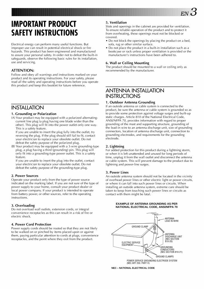
ANTENNA LEAD IN WIRE
ANTENNA DISCHARGE UNIT (NEC SECTION 810-20)
GROUNDING CONDUCTORS (NEC SECTION 810-21)
GROUND CLAMPS
POWER SERVICE GROUNDING ELECTRODE SYSTEM (NEC ART 250. PART H)
NEC – NATIONAL ELECTRICAL CODE
ELECTRIC SERVICE EQUIPMENT
EXAMPLE OF ANTENNA GROUNDING AS PER NATIONAL ELECTRICAL CODE, ANSI/NFPA 70
GROUND CLAMP
ANTENNA INSTALLATIONINSTRUCTIONS1. Outdoor Antenna GroundingIf an outside antenna or cable system is connected to theproduct, be sure the antenna or cable system is grounded so asto provide some protection against voltage surges and built-upstatic charges. Article 810 of the National Electrical Code,ANSI/NFPA 70, provides information with regard to propergrounding of the mast and supporting structure, grounding ofthe lead-in wire to an antenna discharge unit, size of groundingconnectors, location of antenna discharge unit, connection togrounding electrodes, and requirements for the groundingelectrode.
2. LightningFor added protection for this product during a lightning storm,or when it is left unattended and unused for long periods oftime, unplug it from the wall outlet and disconnect the antennaor cable system. This will prevent damage to the product due tolightning and power-line surges.
3. Power LinesAn outside antenna system should not be located in the vicinityof overhead power lines or other electric light or power circuits,or where it can fall into such power lines or circuits. Wheninstalling an outside antenna system, extreme care should betaken to keep from touching such power lines or circuits ascontact with them might be fatal.
4 EN
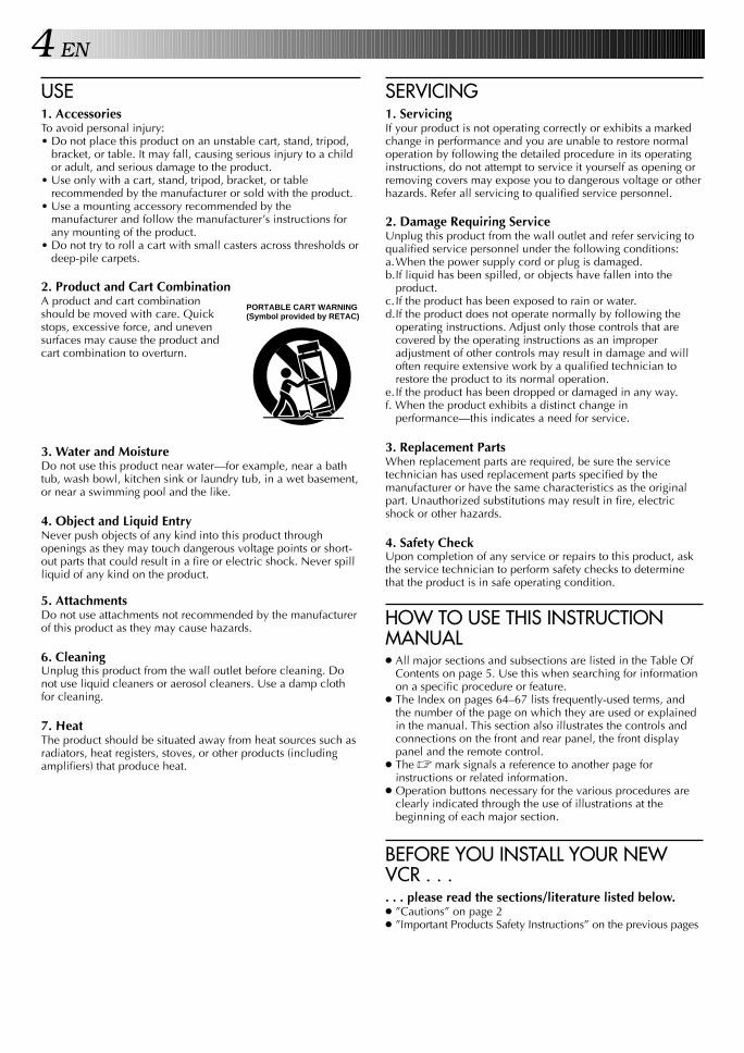
SERVICING1. ServicingIf your product is not operating correctly or exhibits a markedchange in performance and you are unable to restore normaloperation by following the detailed procedure in its operatinginstructions, do not attempt to service it yourself as opening orremoving covers may expose you to dangerous voltage or otherhazards. Refer all servicing to qualified service personnel.
2. Damage Requiring ServiceUnplug this product from the wall outlet and refer servicing toqualified service personnel under the following conditions:a.When the power supply cord or plug is damaged.b.If liquid has been spilled, or objects have fallen into the
product.c. If the product has been exposed to rain or water.d.If the product does not operate normally by following the
operating instructions. Adjust only those controls that arecovered by the operating instructions as an improperadjustment of other controls may result in damage and willoften require extensive work by a qualified technician torestore the product to its normal operation.
e. If the product has been dropped or damaged in any way.f. When the product exhibits a distinct change in
performance—this indicates a need for service.
3. Replacement PartsWhen replacement parts are required, be sure the servicetechnician has used replacement parts specified by themanufacturer or have the same characteristics as the originalpart. Unauthorized substitutions may result in fire, electricshock or other hazards.
4. Safety CheckUpon completion of any service or repairs to this product, askthe service technician to perform safety checks to determinethat the product is in safe operating condition.
HOW TO USE THIS INSTRUCTIONMANUAL● All major sections and subsections are listed in the Table Of
Contents on page 5. Use this when searching for informationon a specific procedure or feature.
● The Index on pages 64–67 lists frequently-used terms, andthe number of the page on which they are used or explainedin the manual. This section also illustrates the controls andconnections on the front and rear panel, the front displaypanel and the remote control.
● The Z mark signals a reference to another page forinstructions or related information.
● Operation buttons necessary for the various procedures areclearly indicated through the use of illustrations at thebeginning of each major section.
BEFORE YOU INSTALL YOUR NEWVCR . . .. . . please read the sections/literature listed below.● ”Cautions” on page 2● ”Important Products Safety Instructions” on the previous pages
USE1. AccessoriesTo avoid personal injury:• Do not place this product on an unstable cart, stand, tripod,
bracket, or table. It may fall, causing serious injury to a childor adult, and serious damage to the product.
• Use only with a cart, stand, tripod, bracket, or tablerecommended by the manufacturer or sold with the product.
• Use a mounting accessory recommended by themanufacturer and follow the manufacturer’s instructions forany mounting of the product.
• Do not try to roll a cart with small casters across thresholds ordeep-pile carpets.
2. Product and Cart CombinationA product and cart combinationshould be moved with care. Quickstops, excessive force, and unevensurfaces may cause the product andcart combination to overturn.
3. Water and MoistureDo not use this product near water—for example, near a bathtub, wash bowl, kitchen sink or laundry tub, in a wet basement,or near a swimming pool and the like.
4. Object and Liquid EntryNever push objects of any kind into this product throughopenings as they may touch dangerous voltage points or short-out parts that could result in a fire or electric shock. Never spillliquid of any kind on the product.
5. AttachmentsDo not use attachments not recommended by the manufacturerof this product as they may cause hazards.
6. CleaningUnplug this product from the wall outlet before cleaning. Donot use liquid cleaners or aerosol cleaners. Use a damp clothfor cleaning.
7. HeatThe product should be situated away from heat sources such asradiators, heat registers, stoves, or other products (includingamplifiers) that produce heat.
PORTABLE CART WARNING (Symbol provided by RETAC)
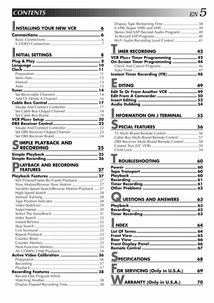
EN 5CONTENTS
Dispiay Tape Remaining Time .................................38S-VHS (Super VHS) and VHS ...................................39Stereo And SAP (Second Audio Program) .................40To Record SAP Programs..........................................40Hi-Fi Audio Recording Level Control .......................41
TIMER RECORDING 42VCR Plus+ Timer Programming ................... 42On-Screen Timer Programming ................... 44
Check And Cancel Programs ...................................46Auto Timer ...............................................................47
Instant Timer Recording (ITR) ....................... 48
EDITING 49Edit To Or From Another VCR ...................... 49Edit From A Camcorder ............................... 50Insert Editing .............................................. 52Audio Dubbing ........................................... 54
INFORMATION ON J TERMINAL 55
SPECIAL FEATURES 56TV Multi-Brand Remote Control ..............................56Cable Box Multi-Brand Remote Control ...................57DBS Receiver Multi-Brand Remote Control ..............58Control Two JVC VCRs ............................................59Child Lock ...............................................................59
TROUBLESHOOTING 60Power ........................................................ 60Tape Transport ............................................ 60Playback .................................................... 60Recording ................................................... 61Timer Recording.......................................... 61Other Problems .......................................... 62
QUESTIONS AND ANSWERS 63Playback .................................................... 63Recording ................................................... 63Timer Recording.......................................... 63
INDEX 64List Of Terms ............................................... 64Front View.................................................. 65Rear View .................................................. 66Front Display Panel..................................... 66Remote Control ........................................... 67
S PECIFICATIONS 68
FOR SERVICING (Only in U.S.A.) 69
WARRANTY (Only in U.S.A.) 70
INSTALLING YOUR NEW VCR 6Connections ...........................................6
Basic Connections .....................................................6S-VIDEO Connection .................................................7
INITIAL SETTINGS 8Plug & Play .................................................. 8Language ................................................... 10Clock .......................................................... 11
Preparation .............................................................. 11Semi-Auto................................................................12Manual ....................................................................13Auto ........................................................................13
Tuner .......................................................... 14Set Receivable Channels ..........................................14Add Or Delete A Channel ........................................16
Cable Box Control ....................................... 17Situate And Connect Controller ...............................17Set Cable Box Output Channel ................................18Set Cable Box Brand ................................................19
VCR Plus+ Setup ......................................... 20DBS Receiver Control................................... 22
Situate And Connect Controller ...............................22Set DBS Receiver Output Channel ...........................23Set DBS Receiver Brand ...........................................24
SIMPLE PLAYBACK ANDRECORDING 25
Simple Playback ......................................... 25Simple Recording ........................................ 26
PLAYBACK AND RECORDINGFEATURES 27
Playback Features ...................................... 27Still Picture/Frame-By-Frame Playback.....................27Slow Motion/Reverse Slow Motion ..........................27Variable-Speed Search/Reverse Motion Playback .....27High-Speed Search ..................................................28Manual Tracking ......................................................28Tape Position Indicator ............................................28Video Stabilizer .......................................................29Superimpose ............................................................30Select The Soundtrack .............................................31Index Search ............................................................32Instant ReView .........................................................32Skip Search ..............................................................32Live Surround ..........................................................32Repeat Playback ......................................................33Counter Reset ..........................................................33Counter Memory .....................................................33Next-Function Memory............................................33AV COMPU LINK Playback .....................................34
Active Video Calibration ............................. 36Preparation ..............................................................36Recording ................................................................37Playback ..................................................................37
Recording Features ..................................... 38Record One Program WhileWatching Another ....................................................38Display Elapsed Recording Time ..............................38
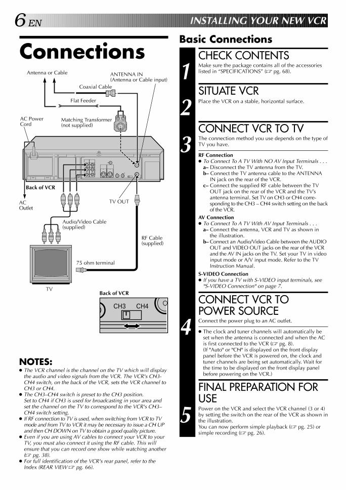
6 EN
Connections
INSTALLING YOUR NEW VCR
NOTES:● The VCR channel is the channel on the TV which will display
the audio and video signals from the VCR. The VCR's CH3-CH4 switch, on the back of the VCR, sets the VCR channel toCH3 or CH4.
● The CH3–CH4 switch is preset to the CH3 position.Set to CH4 if CH3 is used for broadcasting in your area andset the channel on the TV to correspond to the VCR's CH3–CH4 switch setting.
● If RF connection to TV is used, when switching from VCR to TVmode and from TV to VCR it may be necessary to issue a CH UPand then CH DOWN on TV to obtain a good quality picture.
● Even if you are using AV cables to connect your VCR to yourTV, you must also connect it using the RF cable. This willensure that you can record one show while watching another(Z pg. 38).
● For full identification of the VCR's rear panel, refer to theIndex (REAR VIEW Z pg. 66).
Back of VCR
Coaxial Cable
TV
75 ohm terminal
Flat Feeder
Antenna or Cable ANTENNA IN(Antenna or Cable input)
AC PowerCord
Audio/Video Cable(supplied)
ACOutlet
Back of VCR
TV OUT
RF Cable(supplied)
Basic ConnectionsCHECK CONTENTS
1 Make sure the package contains all of the accessorieslisted in “SPECIFICATIONS” (Z pg. 68).
SITUATE VCR
2 Place the VCR on a stable, horizontal surface.
CONNECT VCR TO TV
3 The connection method you use depends on the type ofTV you have.
RF Connection● To Connect To A TV With NO AV Input Terminals . . .
a– Disconnect the TV antenna from the TV.b– Connect the TV antenna cable to the ANTENNA
IN jack on the rear of the VCR.c– Connect the supplied RF cable between the TV
OUT jack on the rear of the VCR and the TV’santenna terminal. Set TV on CH3 or CH4 corre-sponding to the CH3 – CH4 switch setting on the backof the VCR.
AV Connection● To Connect To A TV With AV Input Terminals . . .
a– Connect the antenna, VCR and TV as shown inthe illustration.
b– Connect an Audio/Video Cable between the AUDIOOUT and VIDEO OUT jacks on the rear of the VCRand the AV IN jacks on the TV. Set your TV in videoinput mode or A/V input mode. Refer to the TVInstruction Manual.
S-VIDEO Connection● If you have a TV with S-VIDEO input terminals, see
"S-VIDEO Connection" on page 7.
CONNECT VCR TOPOWER SOURCE
4 Connect the power plug to an AC outlet.
● The clock and tuner channels will automatically beset when the antenna is connected and when the ACis first connected to the VCR (Z pg. 8).(If "Auto" or "CH" is displayed on the front displaypanel before the VCR is powered on, the clock andtuner channels are being set automatically. Wait forthe time to be displayed on the front display panelbefore powering on the VCR.)
FINAL PREPARATION FORUSE
5 Power on the VCR and select the VCR channel (3 or 4)by setting the switch on the rear of the VCR as shown inthe illustration.You can now perform simple playback (Z pg. 25) orsimple recording (Z pg. 26).
Matching Transformer(not supplied)
CH3 CH4

EN 7
NOTES:n Your S-VHS VCR allows you to make high resolution
recordings. For highest quality recordings we recommend thatyou record in the S-VHS mode (Z pg.39)
n To make the most of the Super VHS picture performance werecommend that you use the supplied S-VIDEO cable toconnect your VCR to a TV with an S-VIDEO input connector.
n To operate the VCR with your TV using the S-VIDEO connec-tion, set your TV to the AV mode using the TV's remotecontrol.You can also use the TV/VCR button on the VCR's remotecontrol to set your TV to the AV mode. (Z pg. 56)
S-VIDEO ConnectionCONNECT VCR TO TVa– Connect both the RF cable and the AV cables to the TV as
explained in step 3 of "Basic Connections" (Z pg. 6).b– Connect the S-Video cable between the S-VIDEO OUT
jack on the rear of the VCR and the S-VIDEO IN jack onthe TV.
Antenna or Cable
AC Outlet
S-VIDEO IN
75 ohm terminal
ANTENNA-IN(Antenna or Cable input)
AC Power CordMatching Transformer(Not supplied)
S-VIDEOOUT
TV OUT
RF Cable(supplied)
S-Video Cable(supplied)
Coaxial Cable
Flat Feeder
Audio/VideoCable (supplied)
TV
Back of VCR
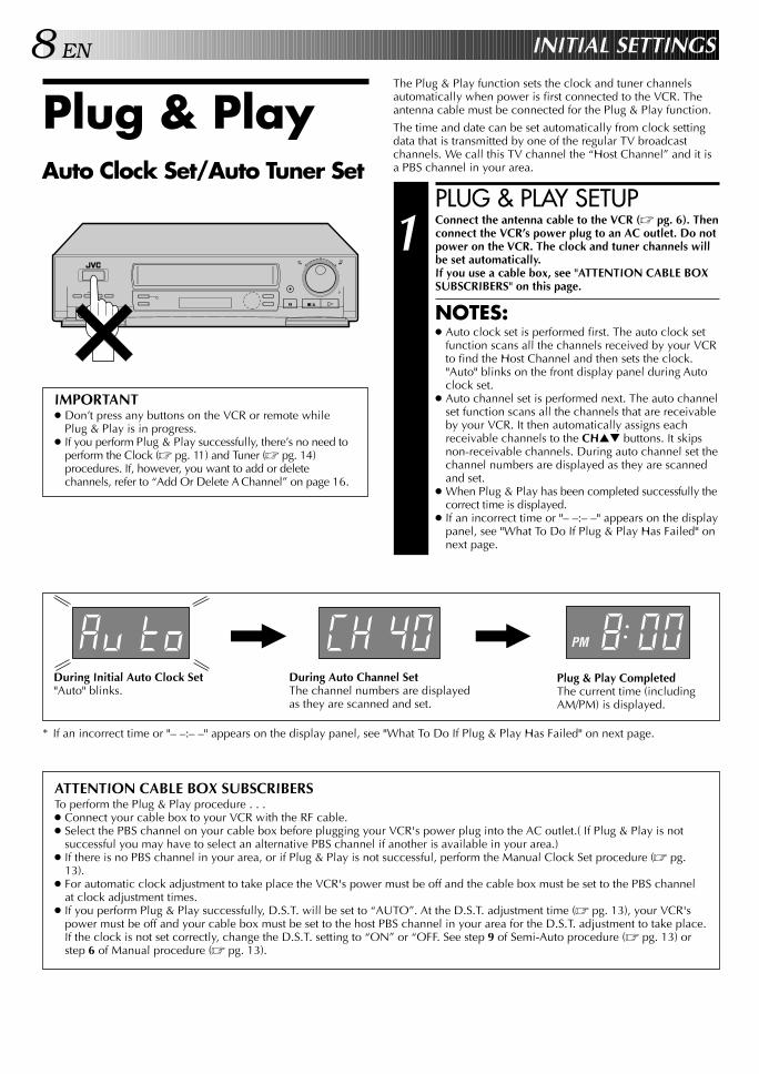
8 EN INITIAL SETTINGS
Plug & PlayThe Plug & Play function sets the clock and tuner channelsautomatically when power is first connected to the VCR. Theantenna cable must be connected for the Plug & Play function.
The time and date can be set automatically from clock settingdata that is transmitted by one of the regular TV broadcastchannels. We call this TV channel the “Host Channel” and it isa PBS channel in your area.Auto Clock Set/Auto Tuner Set
PLUG & PLAY SETUP
1 Connect the antenna cable to the VCR (Z pg. 6). Thenconnect the VCR’s power plug to an AC outlet. Do notpower on the VCR. The clock and tuner channels willbe set automatically.If you use a cable box, see "ATTENTION CABLE BOXSUBSCRIBERS" on this page.
NOTES:● Auto clock set is performed first. The auto clock set
function scans all the channels received by your VCRto find the Host Channel and then sets the clock."Auto" blinks on the front display panel during Autoclock set.
● Auto channel set is performed next. The auto channelset function scans all the channels that are receivableby your VCR. It then automatically assigns eachreceivable channels to the CH▲▼ buttons. It skipsnon-receivable channels. During auto channel set thechannel numbers are displayed as they are scannedand set.
● When Plug & Play has been completed successfully thecorrect time is displayed.
● If an incorrect time or "– –:– –" appears on the displaypanel, see "What To Do If Plug & Play Has Failed" onnext page.
q
IMPORTANT● Don’t press any buttons on the VCR or remote while
Plug & Play is in progress.● If you perform Plug & Play successfully, there’s no need to
perform the Clock (Z pg. 11) and Tuner (Z pg. 14)procedures. If, however, you want to add or deletechannels, refer to “Add Or Delete A Channel” on page 16.
PM
Plug & Play CompletedThe current time (includingAM/PM) is displayed.
During Initial Auto Clock Set"Auto" blinks.
During Auto Channel SetThe channel numbers are displayedas they are scanned and set.
* If an incorrect time or "– –:– –" appears on the display panel, see "What To Do If Plug & Play Has Failed" on next page.
ATTENTION CABLE BOX SUBSCRIBERSTo perform the Plug & Play procedure . . .● Connect your cable box to your VCR with the RF cable.● Select the PBS channel on your cable box before plugging your VCR's power plug into the AC outlet.( If Plug & Play is not
successful you may have to select an alternative PBS channel if another is available in your area.)● If there is no PBS channel in your area, or if Plug & Play is not successful, perform the Manual Clock Set procedure (Z pg.
13).● For automatic clock adjustment to take place the VCR's power must be off and the cable box must be set to the PBS channel
at clock adjustment times.● If you perform Plug & Play successfully, D.S.T. will be set to “AUTO”. At the D.S.T. adjustment time (Z pg. 13), your VCR's
power must be off and your cable box must be set to the host PBS channel in your area for the D.S.T. adjustment to take place.If the clock is not set correctly, change the D.S.T. setting to “ON” or “OFF. See step 9 of Semi-Auto procedure (Z pg. 13) orstep 6 of Manual procedure (Z pg. 13).

EN 9INFORMATION● If "AUTO CLOCK SET" or "SEMI-AUTO CLOCK SET" is selected at the Override Auto Clock Set screen on page 12, the clock
will be adjusted automatically by the host channel every hour on the hour (except for 11:00 PM, midnight, 1:00 AM and 2:00AM) by the incoming PBS channel clock setting data. (This automatic clock adjustment can only be performed when the VCR’spower is turned off. The clock will be adjusted on the hour based on the time displayed on the VCR, not on the actual realtime.) The default setting is "AUTO CLOCK SET".
● If the memory backup fails, because of a power outage or because the AC was removed from the VCR, Plug & Play will beperformed when power is restored to the VCR.
What To Do If Plug & Play Has Failed● If an incorrect time is displayed on the front display panel, you may be receiving the clock setting data of a PBS channel from
an adjacent time zone, or an incorrect PBS channel from a cable TV system. In this case, perform the Semi-Auto (Z pg. 12) orManual Clock Set (Z pg. 13) procedure. Auto channel set has already taken place and it need not be set again.
● If “- -:- -” appears on the display, your antenna cable may not be connected to the VCR, there may not be a Host PBS signalavailable in your area, or your cable box may not be set to the PBS channel. Ensure that the antenna cable is connected correctly. Ifyou use a cable box ensure that your local PBS channel is selected on your cable box (Z pg. 8 ATTENTION CABLE BOX SUB-SCRIBERS). Then power on and power off the VCR; the Plug & Play function will be automatically reactivated and "Auto" will bedisplayed on the VCR's front panel. If Plug & Play is not performed but everything is connected and set correctly, perform theManual Clock Set procedure (Z pg. 13). Auto channel set has not yet taken place, so please also perform the “Set ReceivableChannels” procedure (Z pg. 14).

10 EN INITIAL SETTINGS (cont.)
LanguageThis VCR offers you the choice to view on-screen messages inEnglish, Spanish or French (not including messages superimposedon the TV picture). Select the desired language using thisprocedure. The default setting is "ENGLISH".
TURN ON THE VCR
1 Press POWER.
ACCESS ON-SCREENMENU
2 Press MENU as many times as necessary.
ACCESS CUSTOM SETSCREEN
3 At the Main Menu screen,move the highlight bar(arrow) to “CUSTOM SET”by pressing CH5∞ orSHUTTLE PLUS%fi, thenpress OK.
ACCESS LANGUAGESELECT SCREEN
4 The messages are preset toappear in English. If you wantto see them in Spanish orFrench, move the highlightbar (arrow) to “LANGUAGESELECT” by pressing CH5∞or SHUTTLE PLUS%fi,then press OK.
SELECT LANGUAGE
5 At the Language Selectscreen, move the highlightbar (arrow) to the desiredlanguage by pressingCH5∞ or SHUTTLEPLUS%fi, then pressMENU as many times asnecessary to return to thenormal screen.
q
Turn on the TV and select the VCR channel 3 or 4 (or AVmode).
MAIN MENU
PROGRAM SETFUNCTION SETTUNER SET
= CUSTOM SETVIDEO CALIBRATIONVIDEO STABILIZERPRESS (5,∞), THEN (OK)PRESS (MENU) TO END
LANGUAGE SELECT
=ENGLISHESPAÑOLFRANCAIS
PRESS (5,∞) TO SELECTPRESS (MENU) TO END
CUSTOM SETOVERRIDE
AUTO CLOCK SET=LANGUAGE SELECT
VCR PLUS+ SET-UPDBS RECEIVER OUTPUTDBS RECEIVER BRAND SETJLIP ID NO. SET
PRESS (5,∞), THEN (OK)PRESS (MENU) TO END
MEN
U
OK
POW
ER
1 2 3
4 5 6
7 8
0
9
3
4 ¢
7 8
1 ¡
POWER
MENU
OK
CH
CH
SHUTTLE PLUS

EN 11
ClockPerform clock setting only if the clock has not been set correctlyby the Plug & Play function. Access the Override Auto ClockSet screen to choose the Auto, Semi-Auto or Manual clocksetting procedure. Each procedure starts from step 5. *Autoneed only be selected if Semi-Auto or Manual had previouslybeen selected.
Preparation
TURN ON THE VCR
1 Press POWER.
ACCESS ON-SCREENMENU
2 Press MENU as many times as necessary.
ACCESS CUSTOM SETSCREEN
3 At the Main Menu screen,move the highlight bar(arrow) to “CUSTOM SET”by pressing CH5∞ orSHUTTLE PLUS%fi, thenpress OK.
ACCESS CLOCK SET MODESELECT SCREEN
4 Move the highlight bar(arrow) at the Custom Setscreen to “OVERRIDEAUTO CLOCK SET” bypressing CH5∞ orSHUTTLE PLUS%fi, thenpress OK.
Turn on the TV and select the VCR channel 3 or 4 (or AVmode).
MAIN MENU
PROGRAM SETFUNCTION SETTUNER SET
=CUSTOM SETVIDEO CALIBRATIONVIDEO STABILIZERPRESS (5,∞), THEN (OK)PRESS (MENU) TO END
CUSTOM SET=OVERRIDE
AUTO CLOCK SETLANGUAGE SELECTVCR PLUS+ SET-UPDBS RECEIVER OUTPUTDBS RECEIVER BRAND SETJLIP ID NO. SET
PRESS (5,∞), THEN (OK)PRESS (MENU) TO END
q
POW
ERM
ENU
OK
CH
1 2 3
4 5 6
7 8
0
9
3
4 ¢
7 8
1 ¡
POWER
CH
MENUSHUTTLE PLUS
OK
12 EN INITIAL SETTINGS (cont.)
SELECT MODE
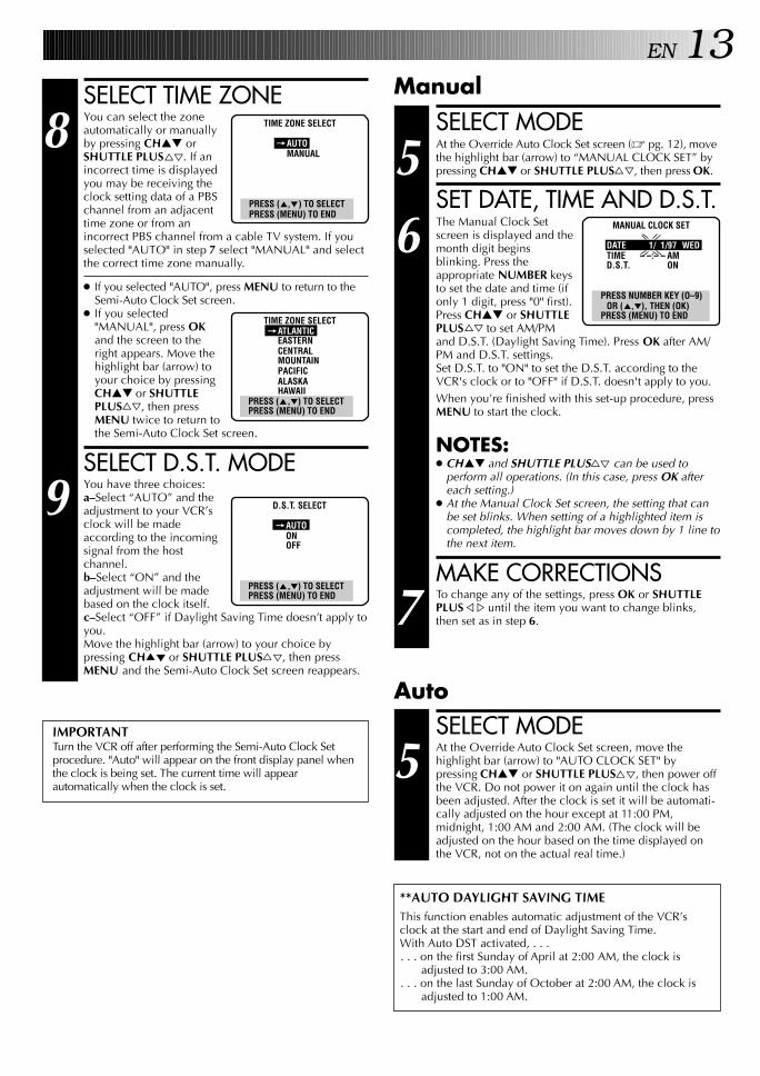
5 At the Override AutoClock Set screen, move thehighlight bar (arrow) to“SEMI-AUTO CLOCK SET”by pressing CH▲▼ orSHUTTLE PLUS%fi, thenpress OK.
ACCESS SELECT SCREENS
6 At the Semi-Auto Clock Setscreen, move the highlightbar (arrow) to the desiredmode by pressing CH▲▼or SHUTTLE PLUS%fi,then press OK.
To select the Host Channel— step 7To select the Time Zone — step 8To select the D.S.T. mode — step 9
NOTE:The time that has been set previously by the Plug &Play function will be erased when any of the threesettings mentioned above is changed.
SELECT HOST CHANNEL
7 You can either select"AUTO", or enter a PBSchannel number. Forautomatic selection, pressMENU if "AUTO" ishighlighted on the HostChannel Select screen. Tomanually select "AUTO" orthe PBS channel, pressCH▲▼ or SHUTTLE PLUS%fi to cycle through"AUTO" or the channel numbers (hold button down tospeed through numbers) and stop when the desirednumber appears. Press MENU and the Semi-Auto ClockSet screen reappears.
NOTES:● For cable box users: Select "AUTO" or the channel
on your VCR that receives the cable box channels,and set the cable box to the PBS channel.
● There are some PBS channels that do not transmitclock setting data.
Semi-Auto
OVERRIDE AUTO CLOCK SET
AUTO CLOCK SET=SEMI–AUTO CLOCK SET
MANUAL CLOCK SET
PRESS (5,∞), THEN (OK)PRESS (MENU) TO END
SEMI–AUTO CLOCK SET
= HOST CHANNEL SELECTTIME ZONE SELECTD.S.T. SELECT
PRESS (5,∞), THEN (OK)PRESS (MENU) TO END
HOST CHANNEL SELECT
(CATV)CH AUTO
PRESS (5,∞) TO SELECTPRESS (MENU) TO END
q
MEN
U
OK
CH
1 2 3
4 5 6
7 8
0
9
3
4 ¢
7 8
1 ¡
MENUSHUTTLE PLUS
OK
CH
EN 13
SELECT MODE
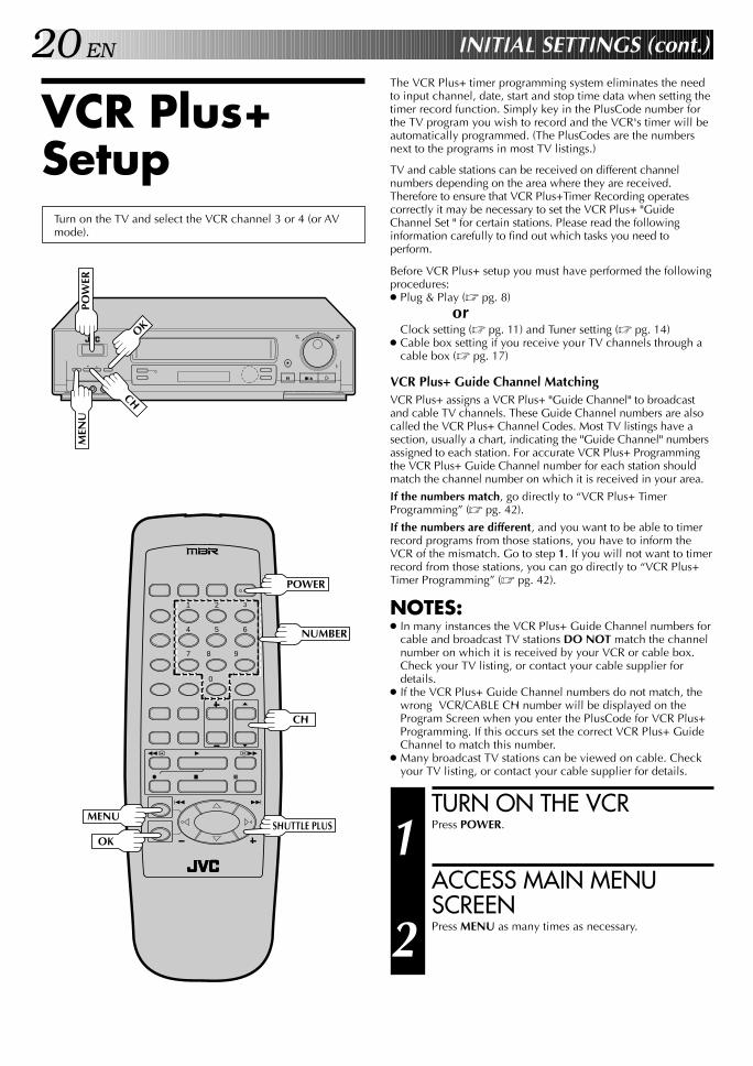
5 At the Override Auto Clock Set screen (Z pg. 12), movethe highlight bar (arrow) to “MANUAL CLOCK SET” bypressing CH▲▼ or SHUTTLE PLUS%fi, then press OK.
SET DATE, TIME AND D.S.T.
6 The Manual Clock Setscreen is displayed and themonth digit beginsblinking. Press theappropriate NUMBER keysto set the date and time (ifonly 1 digit, press "0" first).Press CH▲▼ or SHUTTLEPLUS%fi to set AM/PMand D.S.T. (Daylight Saving Time). Press OK after AM/PM and D.S.T. settings.Set D.S.T. to "ON" to set the D.S.T. according to theVCR's clock or to "OFF" if D.S.T. doesn't apply to you.When you’re finished with this set-up procedure, pressMENU to start the clock.
NOTES:● CH▲▼ and SHUTTLE PLUS%fi can be used to
perform all operations. (In this case, press OK aftereach setting.)
● At the Manual Clock Set screen, the setting that canbe set blinks. When setting of a highlighted item iscompleted, the highlight bar moves down by 1 line tothe next item.
MAKE CORRECTIONS
7 To change any of the settings, press OK or SHUTTLEPLUS until the item you want to change blinks,then set as in step 6.
ManualSELECT TIME ZONE
8 You can select the zoneautomatically or manuallyby pressing CH▲▼ orSHUTTLE PLUS%fi. If anincorrect time is displayedyou may be receiving theclock setting data of a PBSchannel from an adjacenttime zone or from anincorrect PBS channel from a cable TV system. If youselected "AUTO" in step 7 select "MANUAL" and selectthe correct time zone manually.
● If you selected "AUTO", press MENU to return to theSemi-Auto Clock Set screen.
● If you selected"MANUAL", press OKand the screen to theright appears. Move thehighlight bar (arrow) toyour choice by pressingCH▲▼ or SHUTTLEPLUS%fi, then pressMENU twice to return tothe Semi-Auto Clock Set screen.
SELECT D.S.T. MODE
9 You have three choices:a–Select “AUTO” and theadjustment to your VCR’sclock will be madeaccording to the incomingsignal from the hostchannel.b–Select “ON” and theadjustment will be madebased on the clock itself.c–Select “OFF” if Daylight Saving Time doesn’t apply toyou.Move the highlight bar (arrow) to your choice bypressing CH5∞ or SHUTTLE PLUS%fi, then pressMENU and the Semi-Auto Clock Set screen reappears.
AutoSELECT MODE
5 At the Override Auto Clock Set screen, move thehighlight bar (arrow) to "AUTO CLOCK SET" bypressing CH▲▼ or SHUTTLE PLUS%fi, then power offthe VCR. Do not power it on again until the clock hasbeen adjusted. After the clock is set it will be automati-cally adjusted on the hour except at 11:00 PM,midnight, 1:00 AM and 2:00 AM. (The clock will beadjusted on the hour based on the time displayed onthe VCR, not on the actual real time.)
IMPORTANTTurn the VCR off after performing the Semi-Auto Clock Setprocedure. "Auto" will appear on the front display panel whenthe clock is being set. The current time will appearautomatically when the clock is set.
**AUTO DAYLIGHT SAVING TIMEThis function enables automatic adjustment of the VCR’sclock at the start and end of Daylight Saving Time.With Auto DST activated, . . .. . . on the first Sunday of April at 2:00 AM, the clock is
adjusted to 3:00 AM.. . . on the last Sunday of October at 2:00 AM, the clock is
adjusted to 1:00 AM.
TIME ZONE SELECT
=AUTOMANUAL
PRESS (5,∞) TO SELECTPRESS (MENU) TO END
D.S.T. SELECT
=AUTOONOFF
PRESS (5,∞) TO SELECTPRESS (MENU) TO END
MANUAL CLOCK SET
DATE 1/ 1/97 WEDTIME – –:– – AMD.S.T. ON
PRESS NUMBER KEY (O–9)OR (5,∞), THEN (OK)
PRESS (MENU) TO ENDTIME ZONE SELECT=ATLANTIC
EASTERNCENTRALMOUNTAINPACIFICALASKAHAWAII
PRESS (5,∞) TO SELECTPRESS (MENU) TO END
%fi

14 EN
TunerSet Receivable Channels
TURN ON THE VCR
1 Press POWER.
ACCESS MAIN MENUSCREEN
2 Press MENU as many times as necessary.
ACCESS TUNER SETSCREEN
3 Move the highlight bar(arrow) to "TUNER SET" bypressing CH5∞ orSHUTTLE PLUS%fi, thenpress OK.
PERFORM AUTO CHANNELSET
4 Move the highlight bar(arrow) to "AUTOCHANNEL SET" bypressing CH5∞ orSHUTTLE PLUS%fi, thenpress OK.
● Receivable channels inyour area areautomatically assigned tothe CH5∞ buttons, andnon-receivable channelsare skipped.
NOTES:● At the end of Auto
Channel Set, “SCANCOMPLETED” appearson screen.
● If the scan was unsuccessful, “SCAN COMPLETED–NO SIGNAL” appears on screen. Check theconnections and start again.
RETURN TO NORMALSCREEN
5 Press MENU as many times as necessary.
INITIAL SETTINGS (cont.)
Turn on the TV and select the VCR channel 3 or 4 (or AVmode).
MAIN MENU
PROGRAM SETFUNCTION SET
=TUNER SETCUSTOM SETVIDEO CALIBRATIONVIDEO STABILIZERPRESS (5,∞), THEN (OK)PRESS (MENU) TO END
q
POW
ERM
ENU
OK
CH
AUTO CHANNEL SET
SCANNING...
PRESS (MENU) TO END
TUNER SET
BANDAFC
=AUTO CHANNEL SETMANUAL CHANNEL SET
PRESS (5,∞), THEN (OK)PRESS (MENU) TO END
1 2 3
4 5 6
7 8
0
9
3
4 ¢
7 8
1 ¡
POWER
CH
MENUSHUTTLE PLUS
OK

EN 15
The VCR detects the band (TV or CATV) and selects thecorrect band automatically during Auto Channel Set.If necessary, you can check the setting at the Band screenafter Auto Channel Set has set the channels.
● At the Tuner Set screen, move the highlight bar (arrow) to"BAND" by pressing CH5∞ or SHUTTLE PLUS%fi, thenpress OK.
● Press MENU as many times as necessary to return to thenormal screen.
INFORMATION
TUNER SET
=BANDAFCAUTO CHANNEL SETMANUAL CHANNEL SET
PRESS (5,∞), THEN (OK)PRESS (MENU) TO END
BAND
TV=CATV
PRESS (5,∞) TO SELECTPRESS (MENU) TO END
q
MEN
U
OK
CH
1 2 3
4 5 6
7 8
0
9
3
4 ¢
7 8
1 ¡
CH
MENUSHUTTLE PLUS
OK

16 EN
Add Or Delete A ChannelACCESS TUNER SETSCREEN
1 Access by performing steps 2 and 3 of the Tunerprocedure on page 14.
● To add a channel, go to step 2.● To delete a channel, skip to step 4.
ACCESS AFC SCREEN
2 Move the highlight bar (arrow) to "AFC" by pressingCH5∞ or SHUTTLE PLUS%fi, then press OK.
MAKE SELECTION
3 Move the highlight bar(arrow) to "SPCL" bypressing CH5∞ orSHUTTLE PLUS%fi, thenpress MENU to return tothe Tuner Set screen.
● AFC set to SPCL (special)is necessary for tuning oncertain CATV systems.
ACCESS MANUALCHANNEL SET SCREEN
4 Move the highlight bar (arrow) to "MANUAL CHANNELSET" by pressing CH5∞ or SHUTTLE PLUS%fi, thenpress OK.
STORE OR SKIP DESIREDCHANNEL
5 Input the channel numberusing the NUMBER keys orby pressing CH5∞ orSHUTTLE PLUS%fi, thenpress ADD to add orCH.SKIP to delete. Repeatfor each channel you wantto store or skip.
RETURN TO NORMALSCREEN
6 Press MENU as many times as necessary.
INITIAL SETTINGS (cont.)
AFC
NORM=SPCL
PRESS (5,∞) TO SELECTPRESS (MENU) TO END
MANUAL CHANNEL SET
(CATV)CH 125 ADD
SELECT CH NO. ANDPRESS (ADD/SKIP)PRESS (MENU) TO END
q
MEN
U
OK
CH
1 2 3
4 5 6
7 8
0
9
3
4 ¢
7 8
1 ¡
CHCH.SKIP
ADD
MENUSHUTTLE PLUS
OK
NUMBER

EN 17This procedure is required if you receive your TV channelsthrough a cable box (descrambler). The Controller allows theVCR to automatically switch the cable box channel duringtimer-recording. The Controller is effective for recording showsthat have been programmed using VCR Plus+ (Z pg. 42) orOn-Screen Timer Programming (Z pg. 44).
Cable BoxControl
SITUATE CONTROLLER
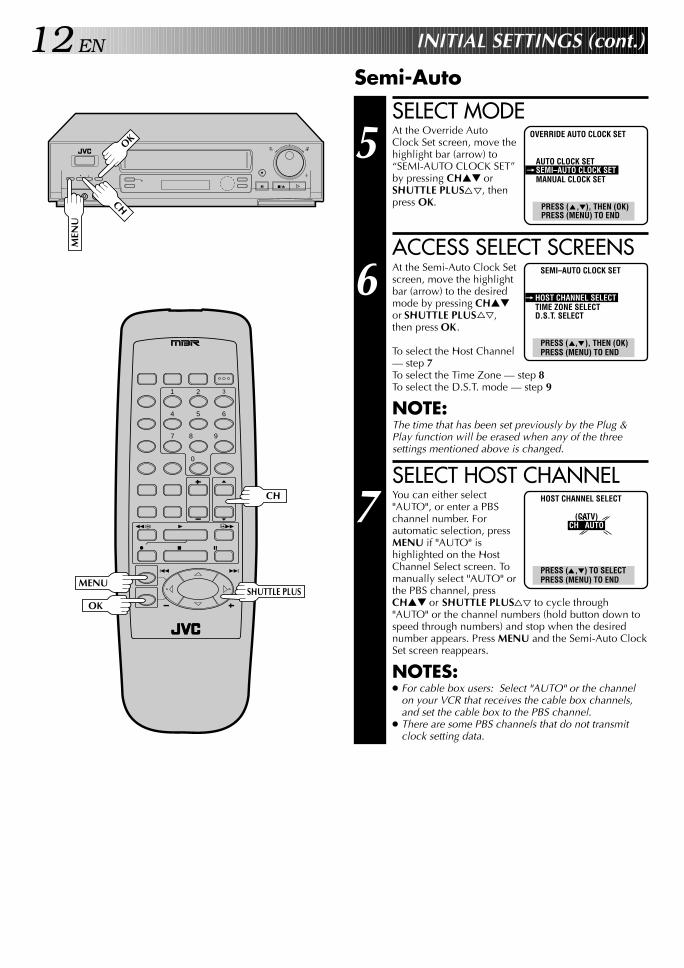
1 Place the Controller so that the path between itstransmitter and the cable box’s remote sensor isunobstructed.
ATTACH CONTROLLER
2 Fasten securely using the supplied adhesive strip.
CONNECT CABLE BOX TOVCR
3 The connection method depends on the type of cablebox you have.
If your cable box has AUDIO and VIDEO OUTconnectors . . .. . . connect them to the AUDIO and VIDEO INconnectors on your VCR; select the correct externalinput mode as described in step 4, 5, 9, 10, 14 on page50 & 51. Set the VCR to channel "AU" to use the cablebox.If your cable box doesn’t have AUDIO and VIDEOOUT connectors . . .. . . connect the antenna output connector on the cablebox to the ANTENNA IN connector on the rear of yourVCR.Set the VCR tuner to the same channel as the cable boxRF output (see page 18 also).
NOTE:When connecting your cable box refer to its instructionmanual.
CONNECT CONTROLLERTO VCR
4 Connect to the CABLE BOX connector on your VCR.
About Your Cable BoxThis VCR has two separate methods to control your Cable Box.
● The VCR's Wireless Remote Control Unit can control yourCable Box.This eliminates the need for a separate Cable Box RemoteControl Unit.
● The VCR's Controller can also control your Cable Box.This allows the VCR to change your Cable Box's channelnumber during timer recording.
Each method must be set up separately. To set up the VCR'sRemote Control unit, refer to page 57. To set up the Controllergo to page 18.
CABLE BOX
Situate And ConnectControllerSuggested Location
Place the cable box on top of the VCR. Attach the VCR'sController to the top of the VCR with the Controller’s transmitterpointed towards the cable box’s remote sensor.
Attention:The Controller can also control a DBS receiver. If both a cablebox and a DBS receiver are used, position the controller so itssignal reaches the remote control sensors of both the cable boxand DBS receiver.
Cable box
Cable box
Your VCR Controller(suggested locations)
Controller
Transmitter
Connectedto VIDEO/AUDIO IN
Your VCR
Connected toANTENNA IN

18 EN INITIAL SETTINGS (cont.)
ACCESS CUSTOM SETSCREEN
3 Press CH5∞ or SHUTTLEPLUS%fi to move thehighlight bar (arrow) to“CUSTOM SET”, thenpress OK.
ACCESS VCR PLUS+ SET-UPSCREEN
4 Press CH5∞ or SHUTTLEPLUS%fi to move thehighlight bar (arrow) to“VCR PLUS+ SET-UP”,then press OK.
ACCESS CABLE BOXOUTPUT SCREEN
5 Press CH5∞ or SHUTTLEPLUS%fi to move thehighlight bar (arrow) to“CABLE BOX OUTPUT”,then press OK.
SELECT CABLE BOXOUTPUT CHANNEL
6 Your selection depends onhow your cable box isconnected to your VCR.
If your cable box isconnected to your VCRusing an RF connection . . .. . . press CH5∞ orSHUTTLE PLUS%fi tomove the highlight bar (arrow) to the channel numberrepresenting the cable box’s output (2–6).If your cable box is connected to your VCR’s AUDIO/VIDEO IN connectors . . .. . . press CH5∞ or SHUTTLE PLUS%fi to move thehighlight bar (arrow) to “ON LINE”.
RETURN TO VCR PLUS+SET-UP SCREEN
7 Press MENU.
Turn on the TV and select the VCR channel 3 or 4 (or AVmode).
TURN ON THE VCR
1 Press POWER.
ACCESS MAIN MENUSCREEN
2 Press MENU as many times as necessary.
Set Cable Box OutputChannel
MAIN MENU
PROGRAM SETFUNCTION SETTUNER SET
=CUSTOM SETVIDEO CALIBRATIONVIDEO STABILIZERPRESS (5,∞), THEN (OK)PRESS (MENU) TO END
CUSTOM SETOVERRIDE
AUTO CLOCK SETLANGUAGE SELECT
=VCR PLUS+ SET-UPDBS RECEIVER OUTPUTDBS RECEIVER BRAND SETJLIP ID NO. SET
PRESS (5,∞), THEN (OK)PRESS (MENU) TO END
VCR PLUS+ SET-UP
GUIDE CHANNEL SETGUIDE CHANNEL MAP
=CABLE BOX OUTPUTCABLE BOX BRAND SET
PRESS (5,∞), THEN (OK)PRESS (MENU) TO END
CABLE BOX OUTPUT=OFF
ON CH2ON CH3ON CH4ON CH5ON CH6ON LINE
PRESS (5,∞) TO SELECTPRESS (MENU) TO END
q
MEN
U
OK
CH
POW
ER
1 2 3
4 5 6
7 8
0
9
3
4 ¢
7 8
1 ¡
POWER
CH
NUMBER
MENUSHUTTLE PLUS
OK

EN 19Set Cable Box Brand
TURN ON CABLE BOX
1 Select a channel other than channel 9 on your CableBox.
ACCESS CABLE BOXBRAND SET SCREEN
2 At the VCR Plus+ Set-Upscreen, press CH5∞ orSHUTTLE PLUS%fi tomove the highlight bar(arrow) to “CABLE BOXBRAND SET”, then pressOK.
ENTER CABLE BOX BRAND
3 Press the appropriateNUMBER keys to enter theCable Box Code from theCABLE BOX BRAND LISTto the right, then press OK.
● If the cable box’schannel changes to 9,setting is complete.
● If there are more than one code number listed foryour brand of cable box, repeat step 3 until the cablebox’s channel changes to 9.
● If the channel does not change after going through allthe code numbers listed for your model of cable box,then try all the other numbers between 1 and 69.
RETURN TO NORMALSCREEN
4 Press MENU as many times as necessary.
You can now set up the VCR Plus+ feature ( Z pg. 20).
CABLE BOX BRAND LIST
BRAND CODE
ARCHER 49, 52, 53, 54CABLEVIEW 49, 53CITIZEN 49, 53CURTIS 9, 10, 62, 63DIAMOND 52, 53, 54EAGLE 30, 31, 32, 33, 34, 35, 36, 37EASTERN 51GC BRAND 49, 53GEMINI 8, 56GENERAL ELECTRIC 67GENERAL INSTRUMENTS 1, 2, 3, 4, 5, 6, 7,8HAMLIN 15, 16, 17,18JERROLD 1, 2, 3, 4, 5, 6, 7, 8MACOM, HITACHI 57, 58, 59MAGNAVOX 30, 31, 32, 33, 34, 35, 43MOVIETIME 44, 45, 46NSC 44, 45, 46OAK 19, 20, 21, 30, 47, 48PANASONIC 24, 25, 26PHILIPS 30, 31, 32, 33, 42PIONEER 13, 14PULSER 49, 53RCA 24, 25, 26REGAL 15, 16, 17, 18, 33REGENCY 51SAMSUNG 8, 13, 49, 50SCIENTIFIC ATLANTA 9, 10, 62, 63SIGMA 19, 20, 21SL MARX 8, 13, 49, 50SPRUCER 24, 25, 26STARGATE 8, 13, 49, 50SYLVANIA 29TEKNIKA 68, 69TELECAPTION 27TELEVIEW 8, 13, 49, 50TEXSCAN 28, 29TOCOM 22, 23, 64, 65, 66UNIKA 52, 53, 54UNIVERSAL 38, 39, 40, 41VIDEOWAY 11, 12, 60, 61VIDEO TECH 55VIDTER 55VIEWSTAR 30, 31, 32, 33, 34, 35, 36, 37ZENITH 11, 12, 60, 61
VCR PLUS+ SET-UP
GUIDE CHANNEL SETGUIDE CHANNEL MAPCABLE BOX OUTPUT
=CABLE BOX BRAND SET
PRESS (5,∞), THEN (OK)PRESS (MENU) TO END
CABLE BOX BRAND SET
1
PRESS NUMBER KEY (0-9)THEN (OK)
PRESS (MENU) TO END
NOTES:● Although the supplied Controller is compatible with many
different cable box brands, it is possible that it will not workwith your cable box.
● If your cable box doesn’t respond to any code between 1 and 69,you can’t use the Controller to change cable box channels. In thiscase, make sure to leave the cable box turned on and tuned to theproper channel before the scheduled start of timer recording.Please contact your cable company about the possibility ofexchanging your current cable box with one that is compat-ible with your VCR.
● The VCR can only change the cable box channel through theController during timer recording.
● If your cable box is one that can’t be operated with a remotecontrol (because it has no remote sensor), you can’t use theController to change its channels. Make sure to leave thecable box turned on and tuned to the proper channel beforethe scheduled start of timer recording.
● For customers in U.S.A.: If you are unable to set the Control-ler, please contact JVC toll free at 1-800-252-5722.
20 EN
q
MEN
U
OK
CH
INITIAL SETTINGS (cont.)
The VCR Plus+ timer programming system eliminates the needto input channel, date, start and stop time data when setting thetimer record function. Simply key in the PlusCode number forthe TV program you wish to record and the VCR's timer will beautomatically programmed. (The PlusCodes are the numbersnext to the programs in most TV listings.)
TV and cable stations can be received on different channelnumbers depending on the area where they are received.Therefore to ensure that VCR Plus+Timer Recording operatescorrectly it may be necessary to set the VCR Plus+ "GuideChannel Set " for certain stations. Please read the followinginformation carefully to find out which tasks you need toperform.
Before VCR Plus+ setup you must have performed the followingprocedures:● Plug & Play (Z pg. 8)
orClock setting (Z pg. 11) and Tuner setting (Z pg. 14)
● Cable box setting if you receive your TV channels through acable box (Z pg. 17)
VCR Plus+ Guide Channel MatchingVCR Plus+ assigns a VCR Plus+ "Guide Channel" to broadcastand cable TV channels. These Guide Channel numbers are alsocalled the VCR Plus+ Channel Codes. Most TV listings have asection, usually a chart, indicating the "Guide Channel" numbersassigned to each station. For accurate VCR Plus+ Programmingthe VCR Plus+ Guide Channel number for each station shouldmatch the channel number on which it is received in your area.
If the numbers match, go directly to “VCR Plus+ TimerProgramming” (Z pg. 42).
If the numbers are different, and you want to be able to timerrecord programs from those stations, you have to inform theVCR of the mismatch. Go to step 1. If you will not want to timerrecord from those stations, you can go directly to “VCR Plus+Timer Programming” (Z pg. 42).
NOTES:● In many instances the VCR Plus+ Guide Channel numbers for
cable and broadcast TV stations DO NOT match the channelnumber on which it is received by your VCR or cable box.Check your TV listing, or contact your cable supplier fordetails.
● If the VCR Plus+ Guide Channel numbers do not match, thewrong VCR/CABLE CH number will be displayed on theProgram Screen when you enter the PlusCode for VCR Plus+Programming. If this occurs set the correct VCR Plus+ GuideChannel to match this number.
● Many broadcast TV stations can be viewed on cable. Checkyour TV listing, or contact your cable supplier for details.
VCR Plus+Setup
Turn on the TV and select the VCR channel 3 or 4 (or AVmode).
POW
ER
1 2 3
4 5 6
7 8
0
9
3
4 ¢
7 8
1 ¡
POWER
CH
MENUSHUTTLE PLUS
OK
NUMBER
TURN ON THE VCR
1 Press POWER.
ACCESS MAIN MENUSCREEN
2 Press MENU as many times as necessary.
EN 21ACCESS CUSTOM SETSCREEN
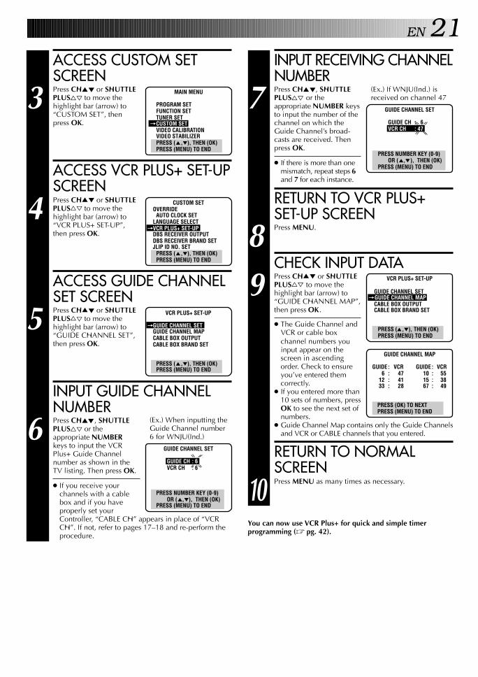
3 Press CH5∞ or SHUTTLEPLUS%fi to move thehighlight bar (arrow) to“CUSTOM SET”, thenpress OK.
ACCESS VCR PLUS+ SET-UPSCREEN
4 Press CH5∞ or SHUTTLEPLUS%fi to move thehighlight bar (arrow) to“VCR PLUS+ SET-UP”,then press OK.
ACCESS GUIDE CHANNELSET SCREEN
5 Press CH5∞ or SHUTTLEPLUS%fi to move thehighlight bar (arrow) to“GUIDE CHANNEL SET”,then press OK.
INPUT GUIDE CHANNELNUMBER
6 Press CH5∞, SHUTTLEPLUS%fi or theappropriate NUMBERkeys to input the VCRPlus+ Guide Channelnumber as shown in theTV listing. Then press OK.
● If you receive yourchannels with a cablebox and if you haveproperly set yourController, “CABLE CH” appears in place of “VCRCH”. If not, refer to pages 17–18 and re-perform theprocedure.
INPUT RECEIVING CHANNELNUMBER
7 Press CH5∞, SHUTTLEPLUS%fi or theappropriate NUMBER keysto input the number of thechannel on which theGuide Channel’s broad-casts are received. Thenpress OK.
● If there is more than onemismatch, repeat steps 6and 7 for each instance.
RETURN TO VCR PLUS+SET-UP SCREEN
8 Press MENU.
CHECK INPUT DATA
9 Press CH5∞ or SHUTTLEPLUS%fi to move thehighlight bar (arrow) to“GUIDE CHANNEL MAP”,then press OK.
● The Guide Channel andVCR or cable boxchannel numbers youinput appear on thescreen in ascendingorder. Check to ensureyou’ve entered themcorrectly.
● If you entered more than10 sets of numbers, pressOK to see the next set ofnumbers.
● Guide Channel Map contains only the Guide Channelsand VCR or CABLE channels that you entered.
RETURN TO NORMALSCREEN
10 Press MENU as many times as necessary.
You can now use VCR Plus+ for quick and simple timerprogramming (Z pg. 42).
(Ex.) If WNJU(Ind.) isreceived on channel 47
MAIN MENU
PROGRAM SETFUNCTION SETTUNER SET
=CUSTOM SETVIDEO CALIBRATIONVIDEO STABILIZERPRESS (5,∞), THEN (OK)PRESS (MENU) TO END
CUSTOM SETOVERRIDE
AUTO CLOCK SETLANGUAGE SELECT
=VCR PLUS+ SET-UPDBS RECEIVER OUTPUTDBS RECEIVER BRAND SETJLIP ID NO. SET
PRESS (5,∞), THEN (OK)PRESS (MENU) TO END
GUIDE CHANNEL SET=
GUIDE CH : 6VCR CH : 47
PRESS NUMBER KEY (0-9)OR (5,∞), THEN (OK)
PRESS (MENU) TO END
(Ex.) When inputting theGuide Channel number6 for WNJU(Ind.)
VCR PLUS+ SET-UP
=GUIDE CHANNEL SETGUIDE CHANNEL MAPCABLE BOX OUTPUTCABLE BOX BRAND SET
PRESS (5,∞), THEN (OK)PRESS (MENU) TO END
GUIDE CHANNEL SET
GUIDE CH : 6VCR CH : 6
PRESS NUMBER KEY (0-9)OR (5,∞), THEN (OK)
PRESS (MENU) TO END
VCR PLUS+ SET-UP
GUIDE CHANNEL SET=GUIDE CHANNEL MAP
CABLE BOX OUTPUTCABLE BOX BRAND SET
PRESS (5,∞), THEN (OK)PRESS (MENU) TO END
GUIDE CHANNEL MAP
GUIDE : VCR GUIDE : VCR 6 : 47 10 : 55 12 : 41 15 : 38 33 : 28 67 : 49
PRESS (OK) TO NEXTPRESS (MENU) TO END

22 EN INITIAL SETTINGS (cont.)
The following procedure is required if you receive satellite channelsthrough a DBS (Direct Broadcast Satellite) Receiver. The Controllerallows the VCR to automatically switch the DBS Receiver's channelsduring timer recording.
NOTES:● The VCR can automatically change the DBS Receiver channels
using the controller when the VCR has been programmed usingOn-Screen Timer Programming (Z pg. 44).Because satellite programming does not use PlusCode; theController can not change the DBS Receiver channels duringVCR Plus+ Timer Recording.
● If a cable box is also used it is recommended that youconnect the DBS receiver to your VCR's A/V inputs and thecable box to your VCR's antenna input.
Situate And Connect Controller
DBS ReceiverControlSuggested LocationPlace the DBS (Direct Broadcast Satellite) receiver on top of theVCR. Attach the VCR's Controller to the top of the VCR with theController’s transmitter pointed towards the DBS receiver'sremote sensor.
Attention:The Controller can also control a cable box. If both a DBSreceiver and a cable box are used, position the controller so itssignal reaches the remote control sensors of both the DBSreceiver and cable box.
About Your DBS ReceiverThis VCR has two separate methods to control your DBS Receiver.
● The VCR's Wireless Remote Control Unit can control yourDBS Receiver.This eliminates the need for a separate DBS Receiver RemoteControl Unit.
● The VCR's Controller can also control your DBS Receiver.This allows the VCR to change your DBS receiver's channelnumber during timer recording.
Each method must be set up separately. To set up the VCR'sRemote Control unit, refer to page 58. To set up the Controllergo to page 23.
CABLE BOX
DBS receiver
Controller(suggested locations)
Your VCR
DBS receiver
ControllerTransmitter
Connectedto VIDEO/AUDIO IN
Your VCR
Connected toANTENNA IN
SITUATE CONTROLLER
1 Place the Controller so that the path between itstransmitter and the DBS receiver's remote sensor isunobstructed.
ATTACH CONTROLLER
2 Fasten securely using the supplied adhesive strips.
CONNECT DBS RECEIVERTO VCR
3 The connection method depends on the type of DBSreceiver you have.
If your DBS receiver has AUDIO and VIDEO OUTconnectors . . .. . . connect them to the AUDIO and VIDEO INconnectors on your VCR; select the correct externalinput mode as described in step 4, 5, 9, 10, 14 on page50 & 51. Set the VCR to channel "AU" to use the DBSreceiver.If your DBS receiver doesn’t have AUDIO and VIDEOOUT connectors . . .. . . connect the antenna output connector on the DBSreceiver to the ANTENNA IN connector on the rear ofyour VCR.Set the VCR's tuner to the same channel as the DBSreceiver's RF output. (See page 23 also.)
NOTE:When connecting your DBS receiver refer to itsinstruction manual.
CONNECT CONTROLLERTO VCR
4 Connect to the CABLE BOX connector on your VCR.
EN 23
q
MEN
U
OK
CH
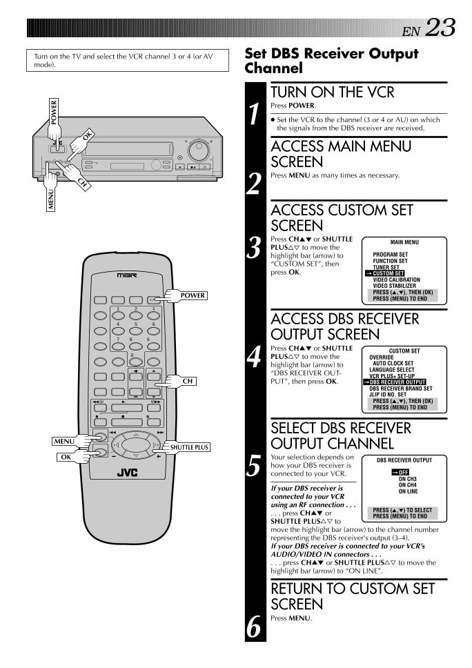
Set DBS Receiver OutputChannel
TURN ON THE VCR
1 Press POWER.
● Set the VCR to the channel (3 or 4 or AU) on whichthe signals from the DBS receiver are received.
ACCESS MAIN MENUSCREEN
2 Press MENU as many times as necessary.
ACCESS CUSTOM SETSCREEN
3 Press CH5∞ or SHUTTLEPLUS%fi to move thehighlight bar (arrow) to“CUSTOM SET”, thenpress OK.
ACCESS DBS RECEIVEROUTPUT SCREEN
4 Press CH5∞ or SHUTTLEPLUS%fi to move thehighlight bar (arrow) to“DBS RECEIVER OUT-PUT”, then press OK.
SELECT DBS RECEIVEROUTPUT CHANNEL
5 Your selection depends onhow your DBS receiver isconnected to your VCR.
If your DBS receiver isconnected to your VCRusing an RF connection . . .. . . press CH5∞ orSHUTTLE PLUS%fi tomove the highlight bar (arrow) to the channel numberrepresenting the DBS receiver's output (3–4).If your DBS receiver is connected to your VCR’sAUDIO/VIDEO IN connectors . . .. . . press CH5∞ or SHUTTLE PLUS%fi to move thehighlight bar (arrow) to “ON LINE”.
RETURN TO CUSTOM SETSCREEN
6 Press MENU.
MAIN MENU
PROGRAM SETFUNCTION SETTUNER SET
= CUSTOM SETVIDEO CALIBRATIONVIDEO STABILIZERPRESS (5,∞), THEN (OK)PRESS (MENU) TO END
CUSTOM SETOVERRIDE
AUTO CLOCK SETLANGUAGE SELECTVCR PLUS+ SET-UP
=DBS RECEIVER OUTPUTDBS RECEIVER BRAND SETJLIP ID NO. SET
PRESS (5,∞), THEN (OK)PRESS (MENU) TO END
DBS RECEIVER OUTPUT
=OFFON CH3ON CH4ON LINE
PRESS (5,∞) TO SELECTPRESS (MENU) TO END
Turn on the TV and select the VCR channel 3 or 4 (or AVmode).
POW
ER
1 2 3
4 5 6
7 8
0
9
3
4 ¢
7 8
1 ¡
POWER
CH
MENUSHUTTLE PLUS
OK

24 EN INITIAL SETTINGS (cont.)
Set DBS Receiver Brand
TURN ON DBS RECEIVER
1 Select a channel other than channel 55, 100 or 205 onyour DBS receiver.
ACCESS DBS RECEIVERBRAND SET SCREEN
2 At the Custom Set screen,press CH5∞ or SHUTTLEPLUS%fi to move thehighlight bar (arrow) to“DBS RECEIVER BRANDSET”, then press OK.
ENTER DBS RECEIVERBRAND
3 Press the appropriateNUMBER keys to enter theDBS Receiver Code fromthe following list, thenpress OK.
● If the DBS receiver's channel changes as follows,setting is complete:
JVC [ 100ECHOSTAR [ 100PRIMESTAR [ 55SONY [ 205RCA [ 205
● After OK is pressed, the program currently receivedthrough the DBS receiver will appear for about 10seconds.
RETURN TO NORMALSCREEN
4 Press MENU as many times as necessary.
NOTES:● It is possible that the Controller will not work with all types of
DBS receiver.● If your DBS receiver doesn’t respond to the code, you can’t
use the Controller to change satellite channels. In this case,make sure to leave the DBS receiver turned on and tuned tothe proper channel before the scheduled start of timerrecording.
● The VCR can only change the satellite channel through theController during timer recording.
● If your DBS receiver is one that can’t be operated with aremote control (because it has no remote sensor), you can’tuse the Controller to change its channels. Make sure to leavethe DBS receiver turned on and tuned to the proper channelbefore the scheduled start of timer recording.
● For customers in U.S.A.: If you are unable to set the Control-ler, please contact JVC toll free at 1-800-252-5722.
CUSTOM SETOVERRIDE
AUTO CLOCK SETLANGUAGE SELECTVCR PLUS+ SET-UPDBS RECEIVER OUTPUT
=DBS RECEIVER BRAND SETJLIP ID NO. SET
PRESS (5,∞), THEN (OK)PRESS (MENU) TO END
DBS RECEIVER BRAND SET
80
PRESS NUMBER KEY (0-9)THEN (OK)
PRESS (MENU) TO END
BRAND CODE
JVC (DISH Network) 91ECHOSTAR (DISH Network) 91PRIMESTAR 90SONY (DSS) 81RCA (DSS) 80
q
MEN
U
OK
CH
1 2 3
4 5 6
7 8
0
9
3
4 ¢
7 8
1 ¡
CH
NUMBER
MENUSHUTTLE PLUS
OK
EN 25SIMPLE PLAYBACK AND RECORDING
SimplePlayback
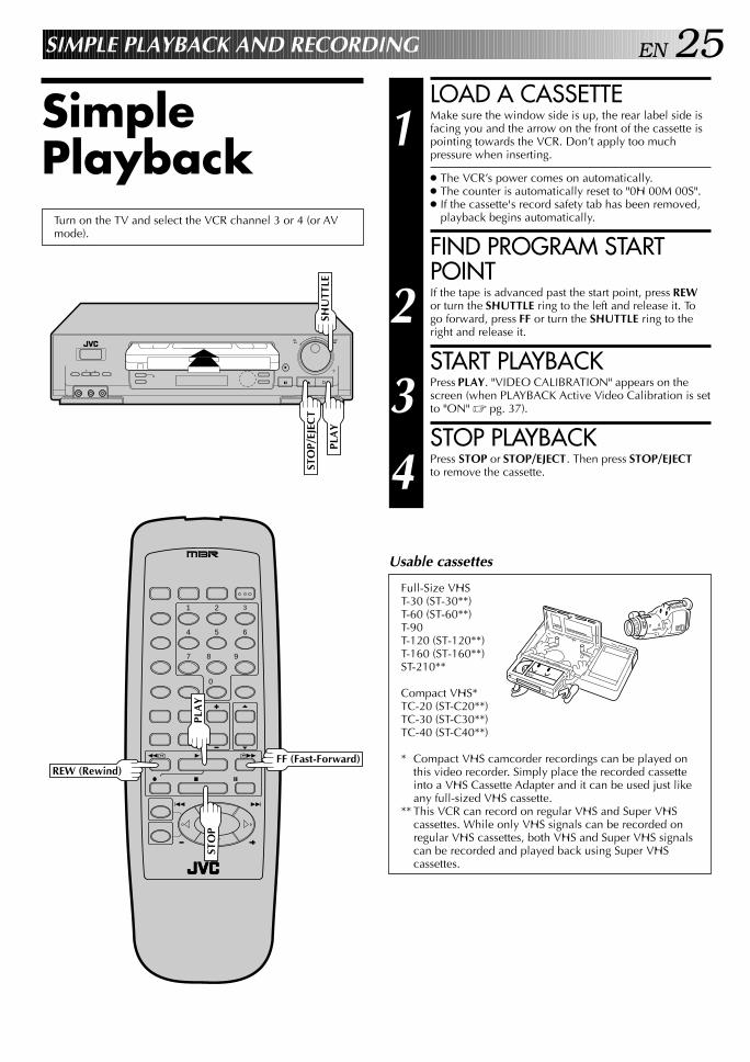
LOAD A CASSETTE
1 Make sure the window side is up, the rear label side isfacing you and the arrow on the front of the cassette ispointing towards the VCR. Don’t apply too muchpressure when inserting.
● The VCR’s power comes on automatically.● The counter is automatically reset to "0H 00M 00S".● If the cassette's record safety tab has been removed,
playback begins automatically.
FIND PROGRAM STARTPOINT
2 If the tape is advanced past the start point, press REWor turn the SHUTTLE ring to the left and release it. Togo forward, press FF or turn the SHUTTLE ring to theright and release it.
START PLAYBACK
3 Press PLAY. "VIDEO CALIBRATION" appears on thescreen (when PLAYBACK Active Video Calibration is setto "ON" Z pg. 37).
STOP PLAYBACK
4 Press STOP or STOP/EJECT. Then press STOP/EJECTto remove the cassette.
Turn on the TV and select the VCR channel 3 or 4 (or AVmode).
Usable cassettes
Full-Size VHST-30 (ST-30**)T-60 (ST-60**)T-90T-120 (ST-120**)T-160 (ST-160**)ST-210**
Compact VHS*TC-20 (ST-C20**)TC-30 (ST-C30**)TC-40 (ST-C40**)
* Compact VHS camcorder recordings can be played onthis video recorder. Simply place the recorded cassetteinto a VHS Cassette Adapter and it can be used just likeany full-sized VHS cassette.
** This VCR can record on regular VHS and Super VHScassettes. While only VHS signals can be recorded onregular VHS cassettes, both VHS and Super VHS signalscan be recorded and played back using Super VHScassettes.
q
STO
P/EJ
ECT
PLA
YSH
UTT
LE
1 2 3
4 5 6
7 8
0
9
3
4 ¢
7 8
1 ¡
REW (Rewind)FF (Fast-Forward)
PLA
YST
OP

26 EN SIMPLE PLAYBACK AND RECORDING (cont.)
SimpleRecording
LOAD A CASSETTE
1 Make sure the record safety tab is intact. If not, cover thehole with adhesive tape before inserting the cassette.
SELECT RECORDINGCHANNEL
2 Press CH5∞. Or press the appropriate NUMBER keys,then press ENTER. (The channel changes after a fewseconds whether you press ENTER or not.)
● If you use the RF connection, by pressing the TV/VCRbutton, select VCR mode to view the program to berecorded.
SET TAPE SPEED
3 Press SP/EP to set the recording speed.
START RECORDING
4 Press and hold REC and press PLAY on the remotecontrol, or press REC on the VCR's front panel.
Active Video Calibration takes place at the beginningof both the first SP and the first EP recording afterinserting the cassette (when RECORD Active VideoCalibration is set to "ON", Z pg. 37).
PAUSE/RESUMERECORDING
5 Press PAUSE. Press PLAY to resume recording.
● During record pause, you can change the recordingchannel by using the CH5∞ buttons or NUMBER keys.
Active Video Calibration will not take place if thetape speed is changed while in record pause mode.
STOP RECORDING
6 Press STOP or STOP/EJECT. Then press STOP/EJECT toremove the cassette.
1 2 3
4 5 6
7 8
0
9
3
4 ¢
7 8
1 ¡
q
STO
PTurn on the TV and select the VCR channel 3 or 4 (or AVmode).
● To prevent accidental recording on a recorded cassette,remove its record safety tab.To record on it later, cover the hole with adhesive tape.
Record safety tab
Accidental erasure prevention
TV/VCR
ENTER
PLAY
RECPAUSE
NUMBER
CH
SP/EP
PAUSE
STOP/
EJECT
PLA
Y
REC
CH
SP/E
P

EN 27
Reverse search
Reverse
Forward search
Forward
Reverse play
Reverse slow motion Slow motion Play
4 steps 5 steps 5 steps 5 steps
SHUTTLE PLUS
4 ¢
PLAYBACK AND RECORDING FEATURES
PlaybackFeatures
Still Picture/Frame-By-Frame Playback
PAUSE DURING PLAYBACK
1 Press PAUSE. If there is vertical jitter, use the CH 5 or ∞button to correct the picture.
ACTIVATE FRAME-BY-FRAMEPLAYBACK
2 Turn the JOG dial to the right for forward frame-by-frame playback, or to the left for reverse frame-by-frameplayback.
ORPress PAUSE repeatedly to advance one frame at a time.
ORPress SHUTTLE PLUS £ repeatedly for forward frame-by-frame playback or SHUTTLE PLUS ™ repeatedlyfor reverse frame-by-frame playback.
To resume normal playback, press PLAY.
Slow Motion/Reverse SlowMotion
ACTIVATE SLOW-MOTION PLAY-BACK
1 For hands-free slow-motion, press and releaseSHUTTLE PLUS ™ during playback to decreasespeed in the forward direction. Continue to press andrelease SHUTTLE PLUS ™ to select the reverse slowmotion, reverse play and reverse search modes.
ORDuring playback or still picture, turn the SHUTTLE ringto the right for forward slow motion, or to the left forreverse slow motion.
ORDuring still picture, press and hold SHUTTLE PLUS £for forward slow motion, or press and hold SHUTTLEPLUS ™ for reverse slow motion. Release to return tostill picture.
To resume normal playback, press PLAY.
Rev
erse
Rev
erse
Reverse SlowPlay
Forward
sear
ch
play
slow motion
search
Still
motion
q
CH
PLA
YSH
UTT
LE
JOG
PAUSE
3
4 ¢
7 8
1 ¡
CH
SHUTTLE PLUS
PAUSE
PLAY
NOTE: Refer to the following for the operations described above.
ACTIVATE VARIABLE-SPEED SEARCH
1 During playback or still, turn the SHUTTLE ring to theright for forward variable-speed search, or to the left forreverse variable-speed search.
ORDuring playback, repeatedly press and release SHUTTLEPLUS ™ or £ to select the search speed.
● To increase the speed in the forward direction, pressand release £ repeatedly to select the variousforward search modes.
● To decrease the speed in the forward direction, pressand release ™.
● To play in reverse slow motion, and in reverse playmode, continue to press ™ repeatedly afterselecting all the forward slow motion modes.
To resume normal playback, press PLAY.
Variable-Speed Search/Reverse Motion Playback
Shuttle Ring ModesForward search : 4 stepsNormal playbackSlow motion : 2 stepsReverse slow motion : 2 stepsReverse playbackReverse search : 4 steps

28 EN
q
PLAYBACK AND RECORDING FEATURES (cont.)
CH
Tape Position IndicatorThe Tape position indicator appearson screen when, from the stopmode, you press FF, REW, or usethe SHUTTLE ring, or perform anIndex Search or Instant ReView. Theposition of " " in relation to "B"(Beginning) or "E" (End) shows youwhere you are on the tape.
NOTES:● "SUPERIMPOSE" must be set to "ON", or the indicator will not
appear (Z pg. 30).● It may take a few seconds for the Tape Position Indicator to be
displayed.
COUNT 0:33:27
B E+ + +
High-Speed SearchACTIVATE HIGH-SPEEDSEARCH
1 During playback or still, turn the SHUTTLE ring all theway to the right for forward high-speed search, or tothe left for reverse high-speed search. By releasingSHUTTLE still picture playback is selected.
● For forward high-speed search, turn the SHUTTLEring all the way to the right and release it within 1second.
● For reverse high-speed search, turn the SHUTTLE ringall the way to the left and release it within 1 second.
ORDuring playback or still, press FF for forward high-speed search, or REW for reverse high-speed search.
To resume normal playback, press PLAY.
NOTE:For short searches, during playback or still, press and hold FF orREW for over 2 seconds. When released, normal playbackresumes.
SHU
TTLE
1 2 3
4 5 6
7 8
0
9
3
4 ¢
7 8
1 ¡
REWFF
CH
PLA
Y
PLAY
Manual TrackingOnce playback begins, the VCR’s automatic tracking function isengaged. If tracking noise appears in the picture, you canoverride this and make the adjustment manually.
ENGAGE MANUALTRACKING MODE
1 During playback, press the CH5 and ∞ buttons on theVCR's front panel simultaneously to cancel theautomatic tracking mode and enable manual trackingadjust.
ADJUST MANUALTRACKING
2 Press CH5 or ∞ on the VCR's front panel or remote.Press briefly for fine adjust, or press and hold for coarseadjust. Watch the screen and continue adjusting untiloptimum picture and sound quality are achieved.
RE-ENGAGE AUTOMATICTRACKING
3 Press the CH5 and ∞ buttons on the VCR's front panelsimultaneously.
● When automatic tracking is re-engaged, VideoCalibration is automatically activated.
NOTES:● To obtain a noiseless still picture it may be necessary to adjust
tracking in slow playback and then engage Pause.● Manual tracking is possible during hands-free slow-motion.
During hands-free slow-motion playback, simply press CH5or ∞ on the VCR's front panel or remote to adjust tracking.
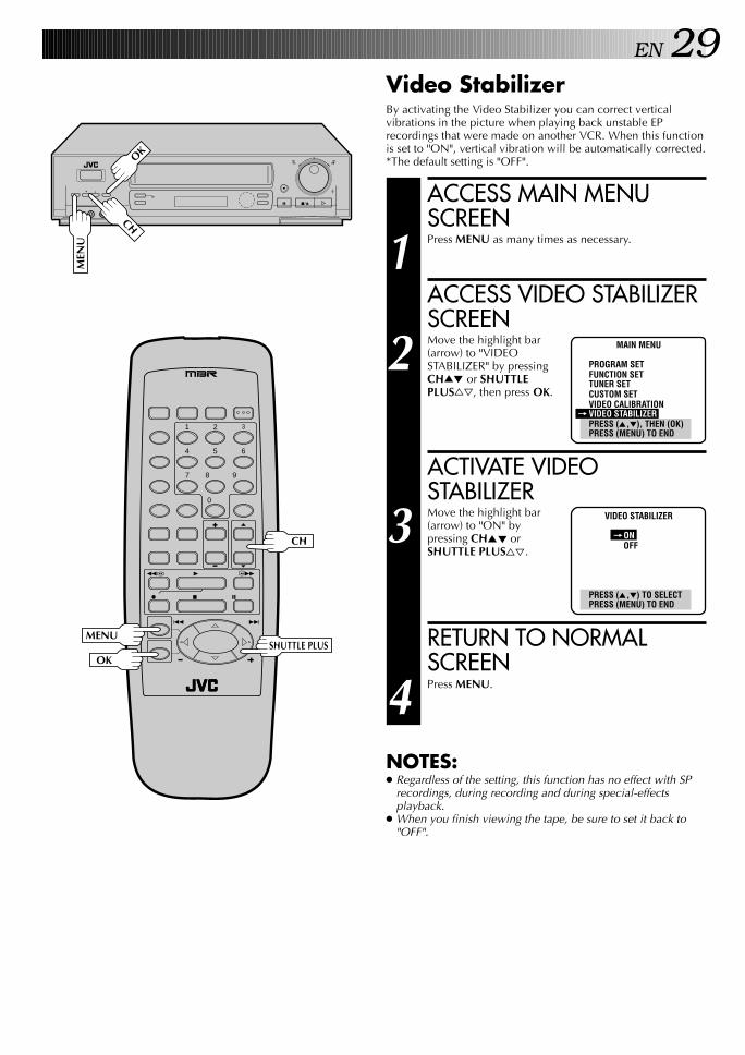
EN 29Video StabilizerBy activating the Video Stabilizer you can correct verticalvibrations in the picture when playing back unstable EPrecordings that were made on another VCR. When this functionis set to "ON", vertical vibration will be automatically corrected.*The default setting is "OFF".
ACCESS MAIN MENUSCREEN
1 Press MENU as many times as necessary.
ACCESS VIDEO STABILIZERSCREEN
2 Move the highlight bar(arrow) to "VIDEOSTABILIZER" by pressingCH5∞ or SHUTTLEPLUS%fi, then press OK.
ACTIVATE VIDEOSTABILIZER
3 Move the highlight bar(arrow) to "ON" bypressing CH5∞ orSHUTTLE PLUS%fi.
RETURN TO NORMALSCREEN
4 Press MENU.
NOTES:● Regardless of the setting, this function has no effect with SP
recordings, during recording and during special-effectsplayback.
● When you finish viewing the tape, be sure to set it back to"OFF".
MAIN MENU
PROGRAM SETFUNCTION SETTUNER SETCUSTOM SETVIDEO CALIBRATION
= VIDEO STABILIZERPRESS (5,∞), THEN (OK)PRESS (MENU) TO END
VIDEO STABILIZER
=ONOFF
PRESS (5,∞) TO SELECTPRESS (MENU) TO END
q
MEN
U
OK
CH
1 2 3
4 5 6
7 8
0
9
3
4 ¢
7 8
1 ¡
CH
MENUSHUTTLE PLUS
OK
30 EN PLAYBACK AND RECORDING FEATURES (cont.)
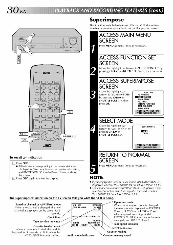
SuperimposeThis function, switchable between ON and OFF, determineswhether or not operational indicators will appear on screen.
To recall an indication
1 Press OSD.n All indications corresponding to the current status are
displayed for 5 seconds, leaving the counter information,and RECORD/PAUSE if in the Record Pause mode, onthe screen.
2 Press OSD again to clear the display.
q
MEN
U
OK
CH
1 2 3
4 5 6
7 8
0
9
3
4 ¢
7 8
1 ¡
CH
MENUSHUTTLE PLUS
OK
OSD
ACCESS MAIN MENUSCREEN
1 Press MENU as many times as necessary.
ACCESS FUNCTION SETSCREEN
2 Move the highlight bar (arrow) to "FUNCTION SET" bypressing CH5∞ or SHUTTLE PLUS%fi, then press OK.
ACCESS SUPERIMPOSESCREEN
3 Move the highlight bar(arrow) to "SUPERIMPOSE"by pressing CH5∞ orSHUTTLE PLUS%fi, thenpress OK.
SELECT MODE
4 Move the highlight bar(arrow) to "ON" or "OFF" bypressing CH5∞ orSHUTTLE PLUS%fi.
RETURN TO NORMALSCREEN
5 Press MENU as many times as necessary.
NOTE:● If you engage the Record Pause mode, RECORD/PAUSE is
displayed whether "SUPERIMPOSE" is set to "ON" or "OFF".● The channel number(except "0" or "AUX" is displayed if you
select a channel on which no signal is received whether"SUPERIMPOSE" is set to "ON" or "OFF".
FUNCTIONAUTO TIMER
=SUPERIMPOSEAUDIO SELECTAUX INPUTSPECIAL FUNCTIONTAPE DUB MODES-VHS MODE
PRESS (5,∞), THEN (OK)PRESS (MENU) TO END
SUPERIMPOSE
=ONOFF
PRESS (5,∞) TO SELECTPRESS (MENU) TO END
CH 125 RECORDTHU 12:00 AM PAUSE
] SP
INDEX-1NORM MEMORY OFFHI–FI COUNT –1:23:45
Tuned-in channel or AUX(iliary) modeWhen the channel is changed, the new
channel is displayed on the screen for 5seconds.
Clock time
Tape position indicator
Operation modeWhen the operation mode is changed,the new mode is displayed — RECORD(5 sec.), PLAY (5 sec.), FF/REW (5 sec.when engaged from Stop mode),RECORD PAUSE (for as long as Pause isengaged), and ITR *:** (5 sec.).
B E+ + +
"Cassette Loaded" markWhen a cassette is loaded, the mark is
displayed for 5 seconds. It blinks when theVCR's EJECT button is pushed.
Tape speed indicator
Counter memory on/off
INDEX indicationCounter reading
Audio mode indicators
The superimposed indication on the TV screen tells you what the VCR is doing.
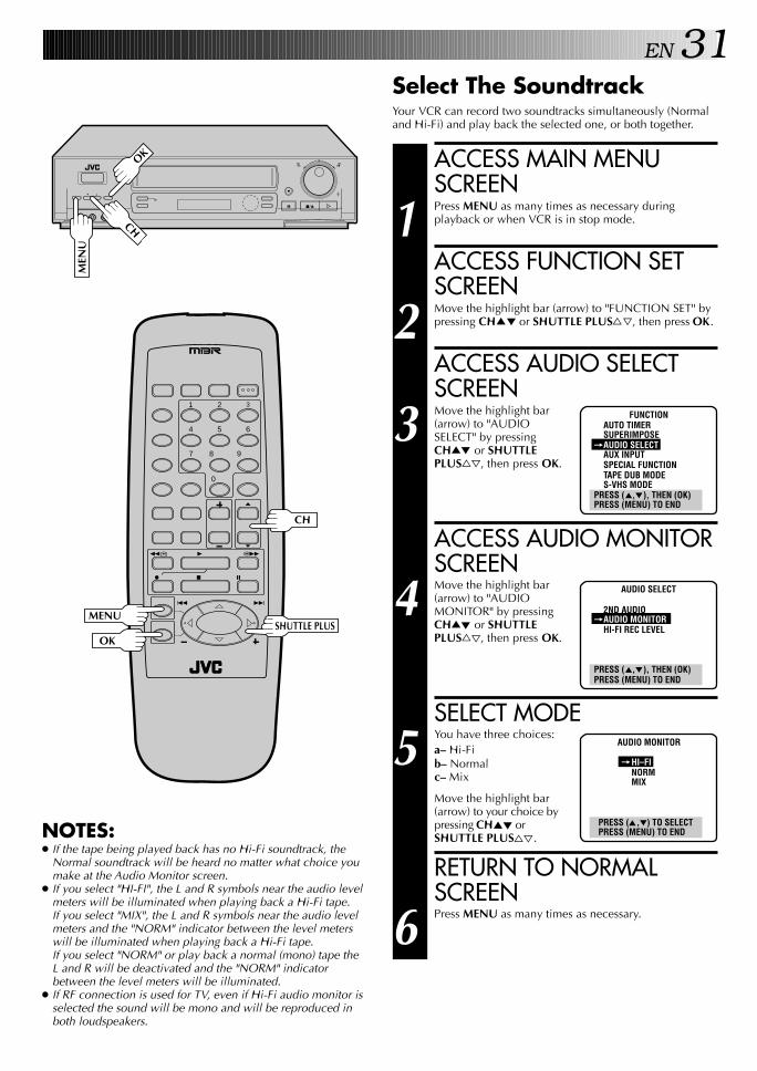
EN 31Select The SoundtrackYour VCR can record two soundtracks simultaneously (Normaland Hi-Fi) and play back the selected one, or both together.
ACCESS MAIN MENUSCREEN
1 Press MENU as many times as necessary duringplayback or when VCR is in stop mode.
ACCESS FUNCTION SETSCREEN
2 Move the highlight bar (arrow) to "FUNCTION SET" bypressing CH5∞ or SHUTTLE PLUS%fi, then press OK.
ACCESS AUDIO SELECTSCREEN
3 Move the highlight bar(arrow) to "AUDIOSELECT" by pressingCH5∞ or SHUTTLEPLUS%fi, then press OK.
ACCESS AUDIO MONITORSCREEN
4 Move the highlight bar(arrow) to "AUDIOMONITOR" by pressingCH5∞ or SHUTTLEPLUS%fi, then press OK.
SELECT MODE
5 You have three choices:a– Hi-Fib– Normalc– Mix
Move the highlight bar(arrow) to your choice bypressing CH5∞ orSHUTTLE PLUS%fi.
RETURN TO NORMALSCREEN
6 Press MENU as many times as necessary.
AUDIO MONITOR
=HI–FINORMMIX
PRESS (5,∞) TO SELECTPRESS (MENU) TO END
q
MEN
U
OK
CH
FUNCTIONAUTO TIMERSUPERIMPOSE
=AUDIO SELECTAUX INPUTSPECIAL FUNCTIONTAPE DUB MODES-VHS MODE
PRESS (5,∞), THEN (OK)PRESS (MENU) TO END
AUDIO SELECT
2ND AUDIO=AUDIO MONITOR
HI-FI REC LEVEL
PRESS (5,∞), THEN (OK)PRESS (MENU) TO END
NOTES:● If the tape being played back has no Hi-Fi soundtrack, the
Normal soundtrack will be heard no matter what choice youmake at the Audio Monitor screen.
● If you select "HI-FI", the L and R symbols near the audio levelmeters will be illuminated when playing back a Hi-Fi tape.If you select "MIX", the L and R symbols near the audio levelmeters and the "NORM" indicator between the level meterswill be illuminated when playing back a Hi-Fi tape.If you select "NORM" or play back a normal (mono) tape theL and R will be deactivated and the "NORM" indicatorbetween the level meters will be illuminated.
● If RF connection is used for TV, even if Hi-Fi audio monitor isselected the sound will be mono and will be reproduced inboth loudspeakers.
1 2 3
4 5 6
7 8
0
9
3
4 ¢
7 8
1 ¡
CH
MENUSHUTTLE PLUS
OK

32 EN
q
PLAYBACK AND RECORDING FEATURES (cont.)
Index SearchIndex codes are placed on the tape at the start of eachrecording. You can find and automatically play back from thestart of any recording using the Index Search function.
START SEARCH
1 While the tape is stopped, press SHUTTLE PLUS ™or £.
ACCESS DISTANT CODE
2 To access a recording 2–9 index codes away, pressSHUTTLE PLUS ™ or £ repeatedly until thecorrect number is displayed on screen (only if SUPER-IMPOSE is set to ON (Z pg. 30). Playback beginsautomatically when the desired recording is located.
● If necessary press REW or FF when play starts tosearch visually to find the very beginning of thedesired program.
NOTE:An index code is not placed on the tape when recording ispaused and then resumed.
Instant ReViewAt the press of a button, you can power up your VCR, rewind thetape and begin viewing the most recent timer-recorded program.
ACTIVATE INSTANT REVIEW
1 After ensuring that the Timer mode is disengaged, pressREVIEW.
● The power comes on and the VCR rewinds to the indexcode indicating the start of the last timer-recordedprogram, then begins playback automatically.
● You can access a program 2–9 index codes awayfrom the current position on the tape. If, for example,you have 5 programs recorded and you want towatch the third one, press REVIEW three times.
● If necessary press REW or FF when play starts tosearch visually to find the very beginning of thedesired program.
● If the tape is already rewound when REVIEW ispressed, it will play the tape from the beginning. Itwill not fast forward to an index code.
● The Instant Review function will also operate if theVCR's power is on.
SKIP OVER UNWANTEDSECTIONS
1 Press SKIP SEARCH 1 to 4 times during playback. Eachpress initiates a 30-second period of fast-motionplayback. Normal playback resumes automatically.
NOTE:To return to normal playback during a Skip Search,press PLAY.
Skip SearchLive SurroundTo enjoy more dynamic stereo sound with Hi-Fi stereo tapes.
ACTIVATE LIVE SURROUND
1 Press LIVE SURROUND during playback or stop.
● The LIVE SURROUND indicator on the VCR lights.● To turn it off, press LIVE SURROUND again.
LIVE S
URROUND
LIVE SURROUND Indicator
1 2 3
4 5 6
7 8
0
9
3
4 ¢
7 8
1 ¡
REWFF
REVIEW
SHUTTLE PLUS
SKIP
SEARCH
LIVE SURROUND
PLAY
PLA
Y
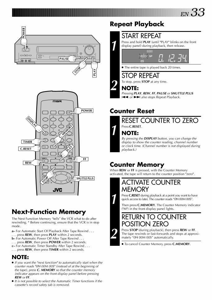
EN 33Repeat Playback
START REPEAT
1 Press and hold PLAY (until "PLAY" blinks on the frontdisplay panel) during playback, then release.
● The entire tape is played back 20 times.
STOP REPEAT
2 To stop, press STOP at any time.
NOTE:Pressing PLAY, REW, FF, PAUSE or SHUTTLE PLUS™ or £ also stops Repeat Playback.
RESET COUNTER TO ZERO
1 Press C.RESET.
NOTE:By pressing the DISPLAY button, you can change thedisplay to show the counter reading, channel numberor clock time. (Channel number is not displayed duringplayback.)
Counter MemoryWhen REW or FF is pressed, with the Counter Memoryactivated, the tape will return to the counter position "zero".
ACTIVATE COUNTERMEMORY
1 Press C.RESET during playback at a point you want to havequick access to later. The counter reads “0H 00M 00S”.
Then press C.MEMORY. The Counter Memory indicator("M") in the front display panel lights.
RETURN TO COUNTERPOSITION ZERO
2 Press STOP (during playback), then press REW or FF.The tape rewinds or fast-forwards and stops at approxi-mately “0H 00M 00S” automatically.
● To cancel Counter Memory, press C.MEMORY.
Counter Reset
Next-Function MemoryThe Next Function Memory “tells” the VCR what to do afterrewinding. * Before continuing, ensure that the VCR is in stopmode.
a– For Automatic Start Of Playback After Tape Rewind . . .. . . press REW, then press PLAY within 2 seconds.b– For Automatic Power Off After Tape Rewind . . .. . . press REW, then press POWER within 2 seconds.c– For Automatic Timer Standby After Tape Rewind . . .. . . press REW, then press TIMER within 2 seconds.
NOTE:● If you want the "next function" to automatically start when the
counter reads "0H 00M 00S" (instead of at the beginning ofthe tape), press C. MEMORY so that the counter memoryindicator appears on the front display panel before pressingREW or FF.
● It is not possible to select the Automatic Timer functions if thecassette's record safety tab is removed.
q
POW
ER
PLA
Y
STOP
PAUSEH M S
V C R
PLAY SP
1 2 3
4 5 6
7 8
0
9
3
4 ¢
7 8
1 ¡
POWER
C.RESET
DISPLAY
TIMER
FF REW
STOP
PLAY
C. MEM
ORY
SHUTTLE PLUS

34 EN PLAYBACK AND RECORDING FEATURES (cont.)
AV COMPU LINK PlaybackYour VCR is compatible with JVC’s AV COMPU LINK components,including amplifiers (or receivers) and televisions. AV COMPULINK provides one touch control of the audio and video compo-nents that are linked via their AV COMPU LINK connectors.For example: simply load a cassette in the VCR and press PLAYand the AV COMPU LINK components automatically power on,the TV's AV mode is selected and the VCR goes into play mode.(PLAY need not be pressed if the cassette's record safety tab isremoved.)
MAKE CONNECTION
1 Connect your VCR to an AV COMPU LINK componentas shown in the illustration on page 35.
● The mini-plug cable is a mono 3.5 mm mini-plug tomono 3.5 mm mini-plug connector.
TURN ON THE VCR
2 Press POWER.
ACCESS MAIN MENUSCREEN
3 Press MENU as many times as necessary.
ACCESS FUNCTION SETSCREEN
4 Press CH5∞ or SHUTTLE PLUS%fi to move thehighlight bar (arrow) to “FUNCTION SET”, then pressOK.
ACCESS SPECIALFUNCTION SCREEN
5 Press CH5∞ or SHUTTLEPLUS%fi to move thehighlight bar (arrow) to“SPECIAL FUNCTION”,then press OK.
q
MEN
U
OK
CH
POW
ER
FUNCTIONAUTO TIMERSUPERIMPOSEAUDIO SELECTAUX INPUT
=SPECIAL FUNCTIONTAPE DUB MODES-VHS MODE
PRESS (5,∞), THEN (OK)PRESS (MENU) TO END
1 2 3
4 5 6
7 8
0
9
3
4 ¢
7 8
1 ¡
POWER
CH
MENUSHUTTLE PLUS
OK
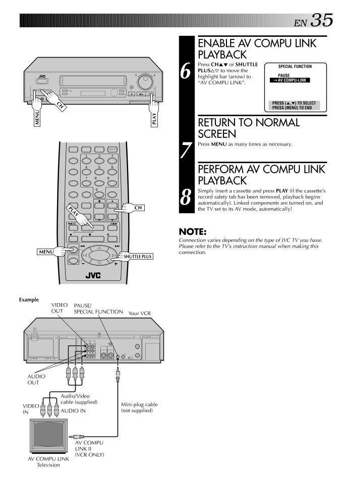
EN 35ENABLE AV COMPU LINKPLAYBACK
6 Press CH5∞ or SHUTTLEPLUS%fi to move thehighlight bar (arrow) to“AV COMPU LINK”.
RETURN TO NORMALSCREEN
7 Press MENU as many times as necessary.
PERFORM AV COMPU LINKPLAYBACK
8 Simply insert a cassette and press PLAY (if the cassette’srecord safety tab has been removed, playback beginsautomatically). Linked components are turned on, andthe TV set to its AV mode, automatically!
NOTE:Connection varies depending on the type of JVC TV you have.Please refer to the TV’s instruction manual when making thisconnection.
SPECIAL FUNCTION
PAUSE=AV COMPU-LINK
PRESS (5,∞) TO SELECTPRESS (MENU) TO END
q
MEN
U
CH
PLA
Y
Example
Your VCR
VIDEOOUT
AV COMPULINK II(VCR ONLY)
AUDIO INVIDEOIN
AUDIOOUT
Audio/Videocable (supplied)
AV COMPU LINKTelevision
1 2 3
4 5 6
7 8
0
9
3
4 ¢
7 8
1 ¡
PLAYCH
MENUSHUTTLE PLUS
Mini-plug cable(not supplied)
PAUSE/SPECIAL FUNCTION

36 EN PLAYBACK AND RECORDING FEATURES (cont.)
Active VideoCalibration
Active Video Calibration checks the condition of the tapeduring recording and playback, and compensates for poorreproduction to provide the best quality recording and playbackpictures. *The default setting for both recording and playback is"ON".
Preparation
TURN ON THE VCR
1 Press POWER.
ACCESS MAIN MENUSCREEN
2 Press MENU as many times as necessary.
ACCESS VIDEOCALIBRATION SCREEN
3 Press CH5∞ or SHUTTLEPLUS %fi to move thehighlight bar (arrow) to“VIDEO CALIBRATION”,then press OK.
SELECT MODE
4 The Recording section ishighlighted. Move the bar(arrow) to "ON" or "OFF"to set the recording modeby pressing CH5∞ orSHUTTLE PLUS %fi, thenpress OK. The playbacksection is then highlighted.Move the bar (arrow) to"ON" or "OFF" to set the playback mode by pressingCH5∞ or SHUTTLE PLUS %fi. Press MENU to return tothe normal screen. (Pressing OK returns the highlight barto the Recording section.)
NOTE:When recording or when playing back tapes recordedon this VCR set the Active Video Calibration to "ON".
Turn on the TV and select the VCR channel 3 or 4 (or AVmode).
1 2 3
4 5 6
7 8
0
9
3
4 ¢
7 8
1 ¡
q
MENU
OK
CH
POWER
MAIN MENU
PROGRAM SETFUNCTION SETTUNER SETCUSTOM SET
=VIDEO CALIBRATIONVIDEO STABILIZERPRESS (5,∞), THEN (OK)PRESS (MENU) TO END
ACTIVE VIDEO CALIBRATION
RECORDING=ON
OFFPLAYBACK
=ONOFF
PRESS (5,∞), THEN (OK)PRESS (MENU) TO END
POW
ER
SHUTTLE PLUS
MEN
U
OK
CH

EN 37RecordingPerform steps 1 – 3 on page 26 ("Simple Recording") beforecontinuing.
ATTENTION:n As calibration takes place before recording actually starts,
there is a delay of about 7 seconds after REC and PLAY onthe remote, or REC on the VCR's front panel, are pressed.To make sure you record the desired scene or programcompletely, first perform the following steps:
1) Press and hold PAUSE, and press REC to engage theRECORD PAUSE mode.● The VCR then automatically checks the condition of
the tape and, after about 7 seconds, re-enters RECORDPAUSE.
2) Press PLAY to start recording.n If you want to bypass Active Video Calibration and start
recording right away, set "RECORDING" to "OFF" in step4 of the Preparation procedure (Z pg. 36).
7 8
0
9
3
4 ¢
7 8
1 ¡
PAUSEREC
START PLAYBACK
1 Press PLAY.
● The VCR adjusts theplayback picture qualitybased on the quality ofthe tape in use.
NOTES:● When using rental tapes,
or tapes recorded on other VCRs, set “PLAYBACK” instep 4 of the Preparation procedure to either “ON” or“OFF” as desired to give the best picture (Z pg. 36).
● The Video Calibration screen only appears at thebeginning of automatic tracking. Even though thescreen doesn't appear after that, the Active Videocalibration function is operative.
● To display the Active Video Calibration screen,“SUPERIMPOSE” must be set to "ON" or the VideoCalibration screen will not appear (Z pg. 30).
START RECORDING
1 Press and hold REC andpress PLAY on the remotecontrol, or press REC onthe VCR's front panel.
● The VCR takes about 7seconds to assess thequality of the tape inuse, then recordingbegins with the picturelevel optimized.
NOTES:● Calibration occurs
immediately prior toboth the first SP and thefirst EP recording afterinserting the cassette. Itdoes not take placeduring recording.
● In the case of timerrecording, calibrationtakes place for both SP and EP before the first timerrecording after inserting the cassette (regardless of thetape speed selected for that recording).
● Once the cassette is ejected, the calibration data iscanceled. The next time the cassette is used forrecording, calibration is re-performed.
● While Active Video Calibration is operative, thePAUSE button will not function.
● To display the Active Video Calibration screen,"SUPERIMPOSE" must be set to "ON" or the ActiveVideo Calibration screen will not appear (Z pg. 30).
PlaybackThe VCR assesses the quality of the tape once you startplayback.
Perform steps 1 and 2 on page 25 ("Simple Playback") beforecontinuing.
q
VIDEO CALIBRATION
START END
ACTIVE VIDEO CALIBRATION+ ++ +
DURING CALIBRATION
CALIBRATION COMPLETE
START END
ACTIVE VIDEO CALIBRATION+ ++ +
PAU
SE
PLA
Y
REC
PLA
Y
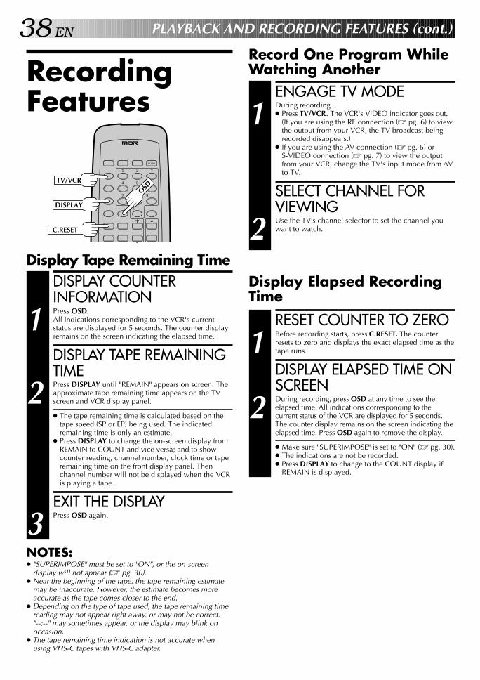
38 EN PLAYBACK AND RECORDING FEATURES (cont.)
Record One Program WhileWatching Another
Display Tape Remaining TimeDISPLAY COUNTERINFORMATION
1 Press OSD.All indications corresponding to the VCR's currentstatus are displayed for 5 seconds. The counter displayremains on the screen indicating the elapsed time.
DISPLAY TAPE REMAININGTIME
2 Press DISPLAY until "REMAIN" appears on screen. Theapproximate tape remaining time appears on the TVscreen and VCR display panel.
● The tape remaining time is calculated based on thetape speed (SP or EP) being used. The indicatedremaining time is only an estimate.
● Press DISPLAY to change the on-screen display fromREMAIN to COUNT and vice versa; and to showcounter reading, channel number, clock time or taperemaining time on the front display panel. Thenchannel number will not be displayed when the VCRis playing a tape.
EXIT THE DISPLAY
3 Press OSD again.
NOTES:● "SUPERIMPOSE" must be set to "ON", or the on-screen
display will not appear (Z pg. 30).● Near the beginning of the tape, the tape remaining estimate
may be inaccurate. However, the estimate becomes moreaccurate as the tape comes closer to the end.
● Depending on the type of tape used, the tape remaining timereading may not appear right away, or may not be correct."--:--" may sometimes appear, or the display may blink onoccasion.
● The tape remaining time indication is not accurate whenusing VHS-C tapes with VHS-C adapter.
RecordingFeatures
1 2 3
4 5 6
7 8
0
9
DISPLAY
C.RESET
TV/VCR
OSD
ENGAGE TV MODE
1 During recording...● Press TV/VCR. The VCR's VIDEO indicator goes out.
(If you are using the RF connection (Z pg. 6) to viewthe output from your VCR, the TV broadcast beingrecorded disappears.)
● If you are using the AV connection (Z pg. 6) orS-VIDEO connection (Z pg. 7) to view the outputfrom your VCR, change the TV's input mode from AVto TV.
SELECT CHANNEL FORVIEWING
2 Use the TV’s channel selector to set the channel youwant to watch.
RESET COUNTER TO ZERO
1 Before recording starts, press C.RESET. The counterresets to zero and displays the exact elapsed time as thetape runs.
DISPLAY ELAPSED TIME ONSCREEN
2 During recording, press OSD at any time to see theelapsed time. All indications corresponding to thecurrent status of the VCR are displayed for 5 seconds.The counter display remains on the screen indicating theelapsed time. Press OSD again to remove the display.
● Make sure "SUPERIMPOSE" is set to "ON" (Z pg. 30).● The indications are not be recorded.● Press DISPLAY to change to the COUNT display if
REMAIN is displayed.
Display Elapsed RecordingTime
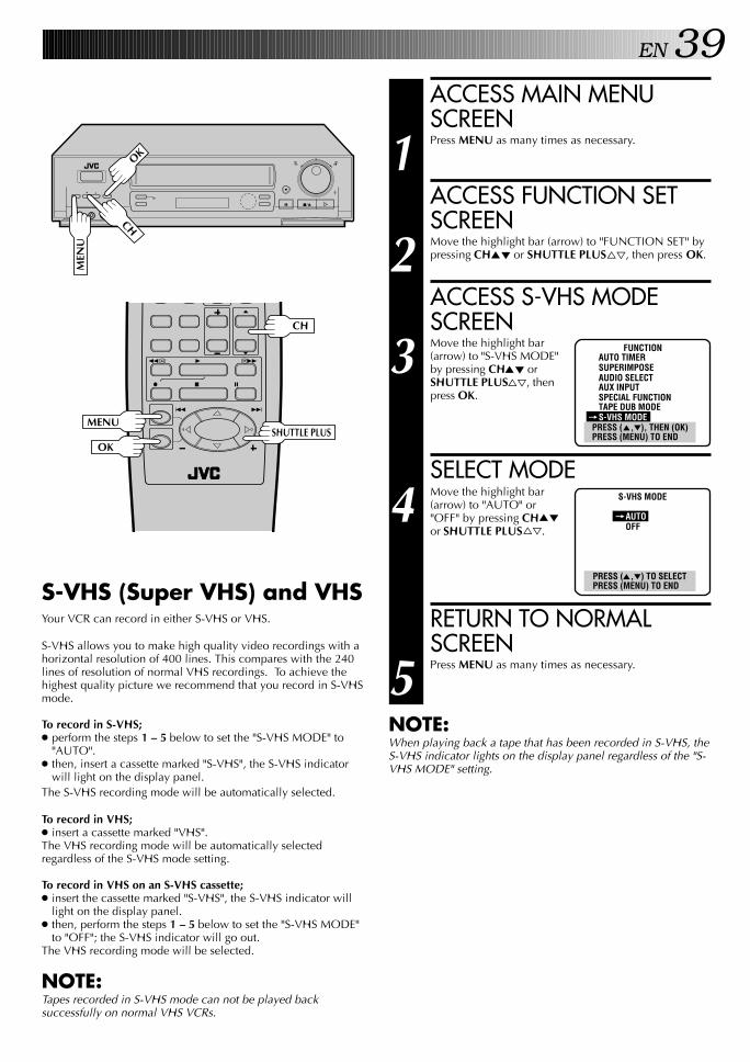
EN 39
q
MEN
U
OK
CH
ACCESS MAIN MENUSCREEN
1 Press MENU as many times as necessary.
ACCESS FUNCTION SETSCREEN
2 Move the highlight bar (arrow) to "FUNCTION SET" bypressing CH5∞ or SHUTTLE PLUS%fi, then press OK.
ACCESS S-VHS MODESCREEN
3 Move the highlight bar(arrow) to "S-VHS MODE"by pressing CH5∞ orSHUTTLE PLUS%fi, thenpress OK.
SELECT MODE
4 Move the highlight bar(arrow) to "AUTO" or"OFF" by pressing CH5∞or SHUTTLE PLUS%fi.
RETURN TO NORMALSCREEN
5 Press MENU as many times as necessary.
FUNCTIONAUTO TIMERSUPERIMPOSEAUDIO SELECTAUX INPUTSPECIAL FUNCTIONTAPE DUB MODE
=S-VHS MODEPRESS (5,∞), THEN (OK)PRESS (MENU) TO END
S-VHS MODE
=AUTOOFF
PRESS (5,∞) TO SELECTPRESS (MENU) TO END
NOTE:When playing back a tape that has been recorded in S-VHS, theS-VHS indicator lights on the display panel regardless of the "S-VHS MODE" setting.
3
4 ¢
7 8
1 ¡
CH
MENUSHUTTLE PLUS
OK
S-VHS (Super VHS) and VHSYour VCR can record in either S-VHS or VHS.
S-VHS allows you to make high quality video recordings with ahorizontal resolution of 400 lines. This compares with the 240lines of resolution of normal VHS recordings. To achieve thehighest quality picture we recommend that you record in S-VHSmode.
To record in S-VHS;● perform the steps 1 – 5 below to set the "S-VHS MODE" to
"AUTO".● then, insert a cassette marked "S-VHS", the S-VHS indicator
will light on the display panel.The S-VHS recording mode will be automatically selected.
To record in VHS;● insert a cassette marked "VHS".The VHS recording mode will be automatically selectedregardless of the S-VHS mode setting.
To record in VHS on an S-VHS cassette;● insert the cassette marked "S-VHS", the S-VHS indicator will
light on the display panel.● then, perform the steps 1 – 5 below to set the "S-VHS MODE"
to "OFF"; the S-VHS indicator will go out.The VHS recording mode will be selected.
NOTE:Tapes recorded in S-VHS mode can not be played backsuccessfully on normal VHS VCRs.

40 EN
Stereo And SAP(Second Audio Program)Your VCR’s built-in MTS decoder enables reception of Multi-channel TV Sound broadcasts.● The ST indicator on the front display panel lights during
stereo broadcast reception, and SAP lights during SAPprogram reception.
● Both indicators light when a stereo program is accompaniedby SAP audio.
To Record Stereo Programs . . .. . . simply follow the basic recording procedure.
To Listen To Stereo Soundtrack During Recording . . .. . . select "HI-FI" at the Audio Monitor screen (Z pg. 31).
To Record SAP Programs . . .ACCESS MAIN MENUSCREEN
1 Press MENU as many times as necessary.
ACCESS FUNCTION SETSCREEN
2 Move the highlight bar (arrow) to "FUNCTION SET" bypressing CH5∞ or SHUTTLE PLUS%fi, then press OK.
ACCESS AUDIO SELECTSCREEN
3 Move the highlight bar (arrow) to "AUDIO SELECT" bypressing CH5∞ or SHUTTLE PLUS%fi, then press OK.
ACCESS 2ND AUDIOSCREEN
4 Move the highlight bar (arrow) to "2ND AUDIO" bypressing CH5∞ or SHUTTLE PLUS%fi, then press OK.
SELECT MODE
5 Move the highlight bar(arrow) to "ON" bypressing CH5∞ orSHUTTLE PLUS%fi.
RETURN TO NORMALSCREEN
6 Press MENU as many times as necessary.
PLAYBACK AND RECORDING FEATURES (cont.)
q
MEN
U
OK
CH
NOTES:● If a SAP program is received, the SAP audio is recorded on
both the Normal and Hi-Fi tracks. The main audio program isnot recorded.
● If a non-SAP program is received, the main audio is recordedon both the Hi-Fi and Normal audio tracks.
2ND AUDIO
=ONOFF
PRESS (5,∞) TO SELECTPRESS (MENU) TO END
1 2 3
4 5 6
7 8
0
9
3
4 ¢
7 8
1 ¡
CH
MENUSHUTTLE PLUS
OK
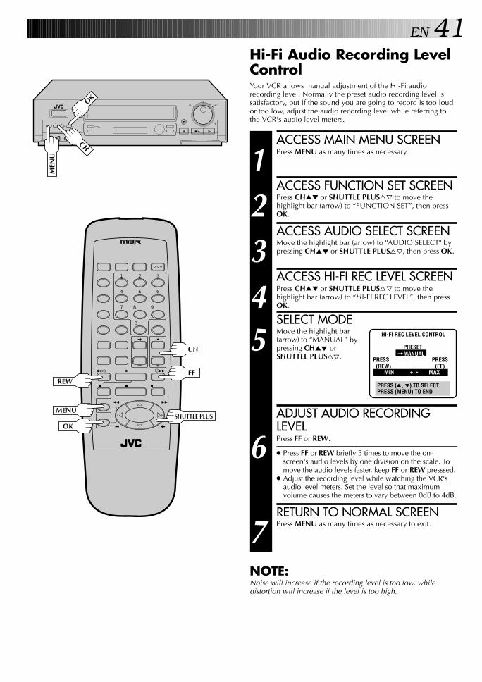
EN 41Hi-Fi Audio Recording LevelControlYour VCR allows manual adjustment of the Hi-Fi audiorecording level. Normally the preset audio recording level issatisfactory, but if the sound you are going to record is too loudor too low, adjust the audio recording level while referring tothe VCR's audio level meters.q
MEN
U
OK
CH ACCESS MAIN MENU SCREEN
1 Press MENU as many times as necessary.
ACCESS FUNCTION SET SCREEN
2 Press CH5∞ or SHUTTLE PLUS%fi to move thehighlight bar (arrow) to “FUNCTION SET”, then pressOK.
ACCESS AUDIO SELECT SCREEN
3 Move the highlight bar (arrow) to "AUDIO SELECT" bypressing CH5∞ or SHUTTLE PLUS%fi, then press OK.
ACCESS HI-FI REC LEVEL SCREEN
4 Press CH5∞ or SHUTTLE PLUS%fi to move thehighlight bar (arrow) to “HI-FI REC LEVEL”, then pressOK.
SELECT MODE
5 Move the highlight bar(arrow) to “MANUAL” bypressing CH5∞ orSHUTTLE PLUS%fi.
ADJUST AUDIO RECORDINGLEVEL
6 Press FF or REW.
● Press FF or REW briefly 5 times to move the on-screen's audio levels by one division on the scale. Tomove the audio levels faster, keep FF or REW presssed.
● Adjust the recording level while watching the VCR'saudio level meters. Set the level so that maximumvolume causes the meters to vary between 0dB to 4dB.
RETURN TO NORMAL SCREEN
7 Press MENU as many times as necessary to exit.
NOTE:Noise will increase if the recording level is too low, whiledistortion will increase if the level is too high.
1 2 3
4 5 6
7 8
0
9
3
4 ¢
7 8
1 ¡
REWFF
CH
MENUSHUTTLE PLUS
OK
HI-FI REC LEVEL CONTROL
PRESET=MANUAL
PRESS PRESS (REW) (FF)
MIN + * MAX
PRESS (5, ∞) TO SELECTPRESS (MENU) TO END

42 EN
VCR Plus+TimerProgramming
● Before VCR Plus+ Timer programming, see "VCR Plus+Setup" on page 20.
● Turn on the TV and select the VCR channel 3 or 4 (or AVmode).
Timer recording allows you to program the VCR to automati-cally record a program which will be broadcast at some futuretime.The timer record function can be programmed using VCR Plus+or On-Screen Timer Programming. (Z pg. 42 or 44)
TIMER RECORDING
VCR PLUS+
PRESS NUMBER KEY (0-9)PRESS (MENU) TO MAIN MENU
LOAD A CASSETTE
1 Make sure the record safety tab is present.
● The VCR’s power comes on automatically.
ACCESS VCR PLUS+ SCREEN
2 Press MENU on the remotecontrol.
● The clock must be set inorder to access the VCRPlus+ screen. If youhaven’t set the clock, theMain Menu screenappears when you pressMENU. Refer to page 8for the Plug & Play procedure or page 11 for the clocksetting procedure.
ENTER PLUSCODE NUMBER
3 Press the appropriate NUMBER keys to enter thePlusCode number printed in the TV listings for the TVprogram you wish to record.
● To make corrections, press CANCEL and input thecorrect PlusCode number.
● If the PlusCode number you input is incorrect,"ERROR" may appear on the screen to advise you ofthe error. This happens when the PlusCode number isfor a program which has already passed. "ERROR" isdisplayed for about 4 seconds and the VCR Plus+screen reappears (step 2).
CHECK INPUT DATA
4 Press OK and the Programscreen appears.The PlusCode number youentered and the matchingTimer-Recording informa-tion is displayed on theProgram screen. Check tomake sure it’s accurate.
● To timer-record daily orweekly serials, press DAILY (NUMBER “8”) orWEEKLY (NUMBER “9”). “DAILY” or “WEEKLY”appears on the Program screen. Pressing the buttonagain makes each corresponding display disappear.
● If you made a mistake, press CANCEL and, afterpressing MENU as many times as necessary to accessthe VCR Plus+ screen, input the correct PlusCodenumber.
SET TAPE SPEED
5 Press SP/EP.
PROGRAM 1(VCR PLUS+ 12345678)
DATE 12/24 WEDSTART 12:00 PMSTOP 1:00 PMCHANNEL 40 SP
PRESS (8=DAILY, 9=WEEKLY SP/EP=REC SPEED)
PRESS (MENU) TO END
q
1 2 3
4 5 6
7 8
0
9
3
4 ¢
7 8
1 ¡
MENU
CANCEL
NUMBER
NUMBER "9"
NUMBER "8"
SP/EP
OK

EN 43CHECK/CORRECT INPUTDATA
6 If the data is correct as it is, go to step 7. If not, pressOK or SHUTTLE PLUS until the item you want tochange begins to blink. Then press the appropriateNUMBER keys, CH5∞ or SHUTTLE PLUS%fi to obtainthe desired setting.
● If you are using a DBS receiver, the BAND indication(TV or CATV or DBS) appears at right of the channelnumber display when OK or SHUTTLE PLUS ispressed. See "ATTENTION FOR DBS RECEIVERUSERS" on page 45.
RETURN TO NORMALSCREEN
7 Press MENU as many times as necessary.
● Press just once to access the Auto Timer screen(Z pg. 47).
ENGAGE TIMER MODE
8 Press TIMER. The VCR turns off automatically.
NOTES:● To disengage the timer before recording starts, press TIMER
again. Pressing once more re-engages it.● In case of a power failure after programming, the VCR’s
memory backup keeps your selections for approximately10 minutes.
● When timer-recording cable channels received through aCable Box, be sure to keep the Cable Box set to ON.
fifi
fifi
1 2 3
4 5 6
7 8
0
9
3
4 ¢
7 8
1 ¡
MENUSHUTTLE PLUS
OK
CH
TIMER
NUMBER
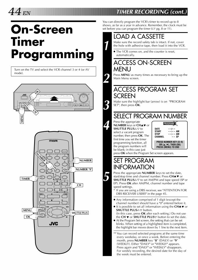
44 EN TIMER RECORDING (cont.)
You can directly program the VCR’s timer to record up to 8shows, as far as a year in advance. Remember, the clock must beset before you can program the timer (Z pg. 8 or 11).On-Screen
TimerProgramming
Turn on the TV and select the VCR channel 3 or 4 (or AVmode).
LOAD A CASSETTE
1 Make sure the record safety tab is intact. If not, coverthe hole with adhesive tape, then load it into the VCR.
● The VCR comes on, and the counter is reset,automatically.
ACCESS ON-SCREENMENU
2 Press MENU as many times as necessary to bring up theMain Menu screen.
ACCESS PROGRAM SETSCREEN
3 Make sure the highlight bar (arrow) is on "PROGRAMSET", then press OK.
SELECT PROGRAM NUMBER
4 Press the appropriateNUMBER keys or CH5∞ orSHUTTLE PLUS%fi toselect a vacant programnumber, then press OK. Thefirst time you set the timerprogramming function, allthe program numbers willbe blank; in this case justpress OK when the Program Set screen appears.
SET PROGRAMINFORMATION
5 Press the appropriate NUMBER keys to set the date,start/stop time and channel number. Press CH5∞ orSHUTTLE PLUS%fi to set AM/PM and tape speed (SP orEP). Press OK after AM/PM, channel number and tapespeed settings.* If you are using a DBS receiver, see "ATTENTION FOR
DBS RECEIVER USERS" in the page 45.
● Any information comprised of 1 digit (except thechannel number) should have a "0" entered before it.
● It is possible to set all information using the CH5∞ orSHUTTLE PLUS%fi button.(In this case, press OK after each setting.) Do not usethe CH ∞ or SHUTTLE PLUSfi button to set the date.
● At the Program Set screen, the setting that can be setblinks. When setting of a highlighted item is completed,the highlight bar moves down by 1 line to the next item.
** You can record selected programs at the same timeevery weekday, or once a week. Before entering themonth, press NUMBER key “8” (DAILY) or “9”(WEEKLY). Either "DAILY" or "WEEKLY" appears.Press again and "DAILY" or "WEEKLY" disappears.For weekly recording, the desired date for the day ofthe week must be entered.
PROGRAM 1
DATE – –/– –START – –:– – AMSTOP – –:– – AMCHANNEL – – SP
PRESS NUMBER KEY (O–9)OR (5,∞), THEN (OK)
PRESS (MENU) TO END
q
MEN
U
CH
OK
1 2 3
4 5 6
7 8
0
9
3
4 ¢
7 8
1 ¡
MENUSHUTTLE PLUS
OK
CH
NUMBER "9"
NUMBER
NUMBER "8"
TIMER

EN 45MAKE CORRECTIONS
6 To change any of the settings, press OK or SHUTTLEPLUS until the item you want to change beginsblinking. Then set as in step 5.
RETURN TO NORMALSCREEN
7 Press MENU as many times as necessary.
● Press just once to access the Auto Timer screen(Z pg. 47).
ENGAGE TIMER MODE
8 Press TIMER. The VCR turns off automatically.
NOTES:● To disengage the timer before recording starts, press TIMER
again. Pressing once more re-engages it.● In case of a power failure after programming, the VCR’s memory
backup keeps your selections for approximately 10 minutes.● If you select "PROGRAM SET" without having set the date and
time, an error message appears. Follow its instructions.● If you enter a start time that has already passed, "ERROR"
appears on the screen and blinks.● Programs that start after midnight must have the next day’s date.● After timer recording is completed, the VCR’s power goes off
automatically.● You can program the timer while a regular recording is in
progress; the on-screen menu will not be recorded.● If the end of tape is reached during timer recording, the
cassette is automatically ejected.● When timer-recording cable or satellite channels through an
external tuner, be sure to keep the cable box or satellitereceiver's power ON.
EXAMPLEIf you program the VCR to timerrecord a show on December 24on channel 40 from 12:00 noonto 1:00 PM in SP mode, thescreen will look like this:
PROGRAM 1
DATE 12/24 WEDSTART 12:00 PMSTOP 1:00 PMCHANNEL 40 SP
PRESS NUMBER KEY (O–9)OR (5,∞), THEN (OK)
PRESS (MENU) TO END
ATTENTION FOR DBS RECEIVER USERSIf you are using a DBS receiver(unless "DBS RECEIVER OUT-PUT" is set to "OFF" Z pg.23),the BAND indication (TV orCATV or DBS) appears to theright of the channel number dis-play. If the channel number thathas been entered requires thatthe band be set, the BAND in-dication starts blinking:
a- TV : To timer-record a regular TV program receivedon the VCR.
b- CATV : To timer-record a cable TV program received onthe VCR, or through a cable box (unless"CABLE BOX OUTPUT" is set to "OFF" Z pg.18).
c- DBS : To timer-record a satellite program receivedthrough a DBS receiver.
Press CH5∞ or SHUTTLE PLUS%fi to select the appropri-ate band, then press OK.● If "BAND" is set to "TV" at the Band screen (Z pg.15),
CATV will not be displayed on the Program screen; if it isset to "CATV", TV will not be displayed.
PROGRAM 1
DATE 12/24 WEDSTART 12:00 PMSTOP 1:00 PMCHANNEL 110 DBS SP
PRESS NUMBER KEY (O–9) OR (5,∞), THEN (OK)
PRESS (MENU) TO END
fifi
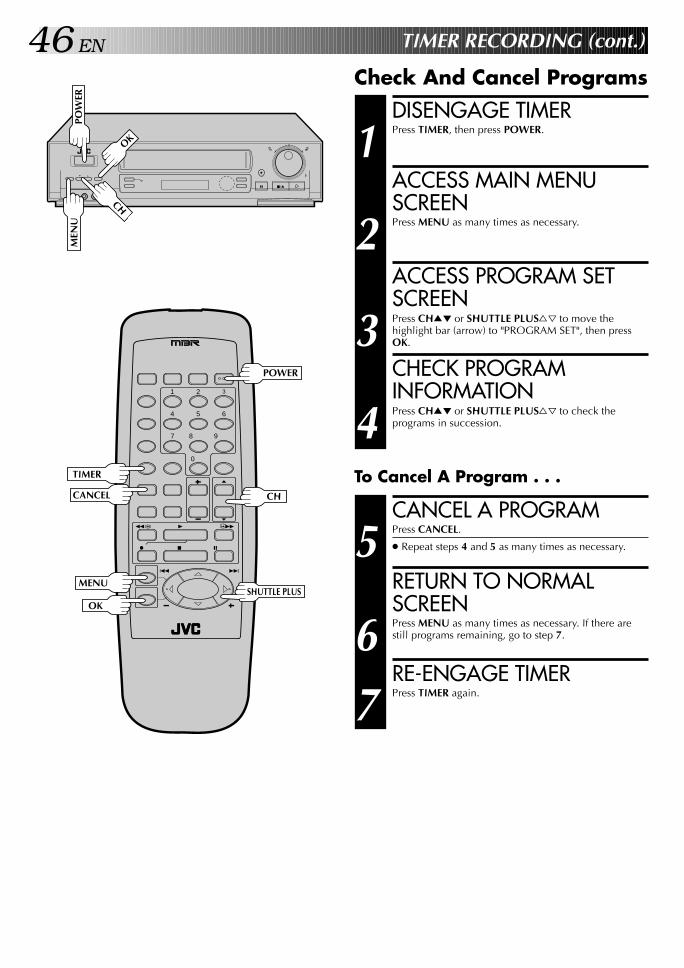
46 EN TIMER RECORDING (cont.)
Check And Cancel Programs
q
MEN
U
OK
CH
POW
ER
DISENGAGE TIMER
1 Press TIMER, then press POWER.
ACCESS MAIN MENUSCREEN
2 Press MENU as many times as necessary.
ACCESS PROGRAM SETSCREEN
3 Press CH5∞ or SHUTTLE PLUS%fi to move thehighlight bar (arrow) to "PROGRAM SET", then pressOK.
CHECK PROGRAMINFORMATION
4 Press CH5∞ or SHUTTLE PLUS%fi to check theprograms in succession.
CANCEL A PROGRAM
5 Press CANCEL.
● Repeat steps 4 and 5 as many times as necessary.
RETURN TO NORMALSCREEN
6 Press MENU as many times as necessary. If there arestill programs remaining, go to step 7.
RE-ENGAGE TIMER
7 Press TIMER again.
To Cancel A Program . . .
1 2 3
4 5 6
7 8
0
9
3
4 ¢
7 8
1 ¡
CANCEL CH
MENUSHUTTLE PLUS
OK
TIMER
POWER
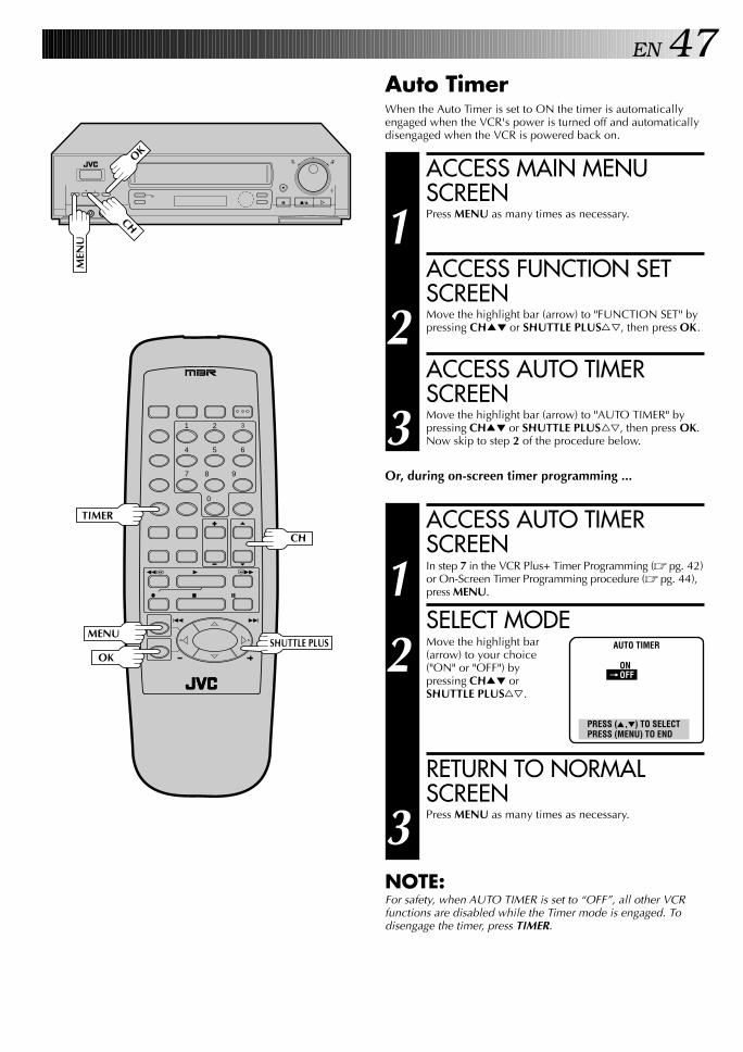
EN 47
ACCESS MAIN MENUSCREEN
1 Press MENU as many times as necessary.
ACCESS FUNCTION SETSCREEN
2 Move the highlight bar (arrow) to "FUNCTION SET" bypressing CH5∞ or SHUTTLE PLUS%fi, then press OK.
ACCESS AUTO TIMERSCREEN
3 Move the highlight bar (arrow) to "AUTO TIMER" bypressing CH5∞ or SHUTTLE PLUS%fi, then press OK.Now skip to step 2 of the procedure below.
Or, during on-screen timer programming ...
ACCESS AUTO TIMERSCREEN
1 In step 7 in the VCR Plus+ Timer Programming (Z pg. 42)or On-Screen Timer Programming procedure (Z pg. 44),press MENU.
SELECT MODE
2 Move the highlight bar(arrow) to your choice("ON" or "OFF") bypressing CH5∞ orSHUTTLE PLUS%fi.
RETURN TO NORMALSCREEN
3 Press MENU as many times as necessary.
NOTE:For safety, when AUTO TIMER is set to “OFF”, all other VCRfunctions are disabled while the Timer mode is engaged. Todisengage the timer, press TIMER.
Auto TimerWhen the Auto Timer is set to ON the timer is automaticallyengaged when the VCR's power is turned off and automaticallydisengaged when the VCR is powered back on.
AUTO TIMER
ON=OFF
PRESS (5,∞) TO SELECTPRESS (MENU) TO END
q
MEN
U
OK
CH
1 2 3
4 5 6
7 8
0
9
3
4 ¢
7 8
1 ¡
MENUSHUTTLE PLUS
OK
CH
TIMER

48 EN
Instant TimerRecording(ITR)
This easy method lets you record for from 30 minutes to 6 hours(selectable in 30-min. increments), and shuts the VCR off afterrecording is finished.
START RECORDING
1 Press REC on the front panel.
ENGAGE ITR MODE
2 Press REC again. REC blinks and 0:30 appears on thefront display panel.
SET RECORDINGDURATION
3 If you want to record for more than 30 minutes, pressREC to extend the time. Each press extends recordingtime by 30 minutes.
NOTES:● You can only perform ITR using the REC button on the VCR's
front panel.● After you set the ITR time, the previous display reappears.● To check the remaining time, press REC once during record-
ing and the remaining time will be displayed for about 5seconds. Be careful not to press REC again within these 5seconds, or you will round the recording time up to the next30 minute increment.
TIMER RECORDING (cont.)
q
REC
V C RR E C
SP
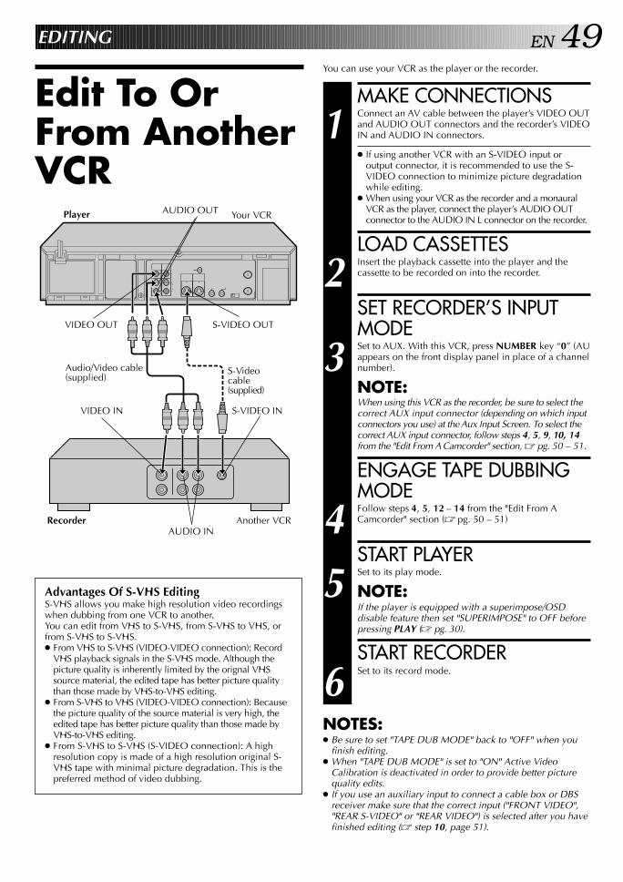
EN 49EDITING
Edit To OrFrom AnotherVCR
You can use your VCR as the player or the recorder.
MAKE CONNECTIONS
1 Connect an AV cable between the player’s VIDEO OUTand AUDIO OUT connectors and the recorder’s VIDEOIN and AUDIO IN connectors.
● If using another VCR with an S-VIDEO input oroutput connector, it is recommended to use the S-VIDEO connection to minimize picture degradationwhile editing.
● When using your VCR as the recorder and a monauralVCR as the player, connect the player’s AUDIO OUTconnector to the AUDIO IN L connector on the recorder.
LOAD CASSETTES
2 Insert the playback cassette into the player and thecassette to be recorded on into the recorder.
SET RECORDER’S INPUTMODE
3 Set to AUX. With this VCR, press NUMBER key “0” (AUappears on the front display panel in place of a channelnumber).
NOTE:When using this VCR as the recorder, be sure to select thecorrect AUX input connector (depending on which inputconnectors you use) at the Aux Input Screen. To select thecorrect AUX input connector, follow steps 4, 5, 9, 10, 14from the "Edit From A Camcorder" section, Z pg. 50 – 51.
ENGAGE TAPE DUBBINGMODE
4 Follow steps 4, 5, 12 – 14 from the "Edit From ACamcorder" section (Z pg. 50 – 51)
START PLAYER
5 Set to its play mode.
NOTE:If the player is equipped with a superimpose/OSDdisable feature then set "SUPERIMPOSE" to OFF beforepressing PLAY (Z pg. 30).
START RECORDER
6 Set to its record mode.
NOTES:● Be sure to set "TAPE DUB MODE" back to "OFF" when you
finish editing.● When "TAPE DUB MODE" is set to "ON" Active Video
Calibration is deactivated in order to provide better picturequality edits.
● If you use an auxiliary input to connect a cable box or DBSreceiver make sure that the correct input ("FRONT VIDEO","REAR S-VIDEO" or "REAR VIDEO") is selected after you havefinished editing (Z step 10, page 51).
Your VCRPlayer
VIDEO OUT
S-VIDEO INVIDEO IN
S-VIDEO OUT
Advantages Of S-VHS EditingS-VHS allows you make high resolution video recordingswhen dubbing from one VCR to another.You can edit from VHS to S-VHS, from S-VHS to VHS, orfrom S-VHS to S-VHS.● From VHS to S-VHS (VIDEO-VIDEO connection): Record
VHS playback signals in the S-VHS mode. Although thepicture quality is inherently limited by the orignal VHSsource material, the edited tape has better picture qualitythan those made by VHS-to-VHS editing.
● From S-VHS to VHS (VIDEO-VIDEO connection): Becausethe picture quality of the source material is very high, theedited tape has better picture quality than those made byVHS-to-VHS editing.
● From S-VHS to S-VHS (S-VIDEO connection): A highresolution copy is made of a high resolution original S-VHS tape with minimal picture degradation. This is thepreferred method of video dubbing.
S-Videocable(supplied)
AUDIO INAnother VCRRecorder
AUDIO OUT
Audio/Video cable(supplied)

50 EN EDITING (cont.)
q
Edit From ACamcorder
You can use a camcorder as the player and your VCR as therecorder.
MAKE CONNECTIONS
1 Connect an AV cable between the camcorder’s VIDEOOUT and AUDIO OUT connectors and your VCR’sVIDEO IN and AUDIO IN connectors.
● If connecting a camcorder with an S-VIDEO outputconnector, it is recommended to use the S-VIDEOconnection to minimize picture degradation whileediting.
● When a Master Edit Control-equipped JVC camcorder isused, the camcorder is capable of controlling your VCR.The mini-plug cable is a mono 3.5 mm mini-plug tomono 3.5 mm mini-plug connector.
● If connecting to a camcorder with a monaural output,connect the audio output connector on thecamcorder to AUDIO IN L of the VCR.
LOAD A CASSETTE
2 Insert the cassette to be recorded on into the recorder.
SET RECORDER’S INPUTMODE
3 Press NUMBER key “0” to set to AUX.
ACCESS MAIN MENUSCREEN
4 Press MENU as many times as necessary.
ACCESS FUNCTION SETSCREEN
5 Press CH5∞ or SHUTTLE PLUS%fi to move the highlightbar (arrow) to “FUNCTION SET”, then press OK.
If you’re using a JVC Master Edit Control-equippedcamcorder — step 6If not — step 9
ACCESS SPECIALFUNCTION SCREEN
6 Press CH5∞ or SHUTTLE PLUS%fi to move thehighlight bar (arrow) to “SPECIAL FUNCTION”, thenpress OK.
SELECT MODE
7 Press CH5∞ or SHUTTLEPLUS%fi to move thehighlight bar (arrow) to“PAUSE”.
SPECIAL FUNCTION
=PAUSEAV COMPU-LINK
PRESS (5,∞) TO SELECTPRESS (MENU) TO END
Recorder Your VCR
To rear panel PAUSE/SPECIAL FUNCTIONconnector
Mini-plug cable (not supplied)(JVC camcorder only)
Audio/Videocable (supplied)
VIDEO OUT
AUDIO OUT
EDIT
Player
Camcorder
VIDEO IN
AUDIOIN
4 5 6
7 8
0
9
3
4 ¢
7 8
1 ¡
MENUSHUTTLE PLUS
OK
CH
NUMBER "0"
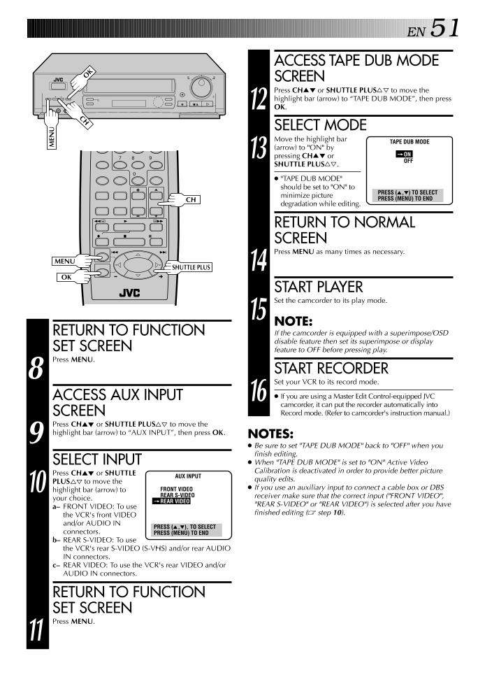
EN 51ACCESS TAPE DUB MODESCREEN
12 Press CH5∞ or SHUTTLE PLUS%fi to move thehighlight bar (arrow) to “TAPE DUB MODE”, then pressOK.
SELECT MODE
13 Move the highlight bar(arrow) to "ON" bypressing CH5∞ orSHUTTLE PLUS%fi.
● "TAPE DUB MODE"should be set to "ON" tominimize picturedegradation while editing.
RETURN TO NORMALSCREEN
14 Press MENU as many times as necessary.
START PLAYER
15 Set the camcorder to its play mode.
NOTE:If the camcorder is equipped with a superimpose/OSDdisable feature then set its superimpose or displayfeature to OFF before pressing play.
START RECORDER
16 Set your VCR to its record mode.
● If you are using a Master Edit Control-equipped JVCcamcorder, it can put the recorder automatically intoRecord mode. (Refer to camcorder's instruction manual.)
NOTES:● Be sure to set "TAPE DUB MODE" back to "OFF" when you
finish editing.● When "TAPE DUB MODE" is set to "ON" Active Video
Calibration is deactivated in order to provide better picturequality edits.
● If you use an auxiliary input to connect a cable box or DBSreceiver make sure that the correct input ("FRONT VIDEO","REAR S-VIDEO" or "REAR VIDEO") is selected after you havefinished editing (Z step 10).
q
RETURN TO FUNCTIONSET SCREEN
8 Press MENU.
ACCESS AUX INPUTSCREEN
9 Press CH5∞ or SHUTTLE PLUS%fi to move thehighlight bar (arrow) to “AUX INPUT”, then press OK.
SELECT INPUT
10 Press CH5∞ or SHUTTLEPLUS%fi to move thehighlight bar (arrow) toyour choice.a– FRONT VIDEO: To use
the VCR's front VIDEOand/or AUDIO INconnectors.
b– REAR S-VIDEO: To usethe VCR's rear S-VIDEO (S-VHS) and/or rear AUDIOIN connectors.
c– REAR VIDEO: To use the VCR's rear VIDEO and/orAUDIO IN connectors.
RETURN TO FUNCTIONSET SCREEN
11 Press MENU.
AUX INPUT
FRONT VIDEOREAR S-VIDEO
=REAR VIDEO
PRESS (5,∞), TO SELECTPRESS (MENU) TO END
TAPE DUB MODE
=ONOFF
PRESS (5,∞) TO SELECTPRESS (MENU) TO END
MEN
U
OK
CH
7 8
0
9
3
4 ¢
7 8
1 ¡
CH
MENUSHUTTLE PLUS
OK

52 EN
q
Insert editing replaces part of the recorded scene with newmaterial. Both the picture and Hi-Fi audio soundtrack arereplaced with new ones, while the normal audio soundtrackremains unchanged. If you wish to change the normal audiotrack as well, use the audio dubbing function simultaneously.Use your VCR as the recorder.
Insert Editing
EDITING (cont.)
MAKE CONNECTIONS
1 Connect the player's VIDEO OUT and AUDIO OUTconnectors to your VCR's VIDEO IN and AUDIO IN onthe front panel.
SET INPUT MODE
2 Press NUMBER key "0". "AU" appears in place of achannel number.
● Be sure to select the correct AUX input connector atthe Aux Input screen. (To select the correct AUX inputconnector, follow steps 4, 5, 9, 10, 14 from the "EditFrom A Camcorder" section Z pg. 50).
LOCATE END POINT
3 Load the recording cassette into your VCR, and play itback to determine the edit-out point (the end of thesegment to be replaced) using the JOG/SHUTTLEcontrols or SHUTTLE PLUS ™£ and PAUSE.
RESET THE COUNTER
4 Press C.RESET to change the counter display to"0H00M00S".
LOCATE START POINT
5 Determine the edit-in point (the beginning of thesegment to be replaced) using the JOG/SHUTTLEcontrols or SHUTTLE PLUS ™£ and PAUSE.
● Be sure to engage the Still mode at the edit-in point.
Before insert editing
After insert editing
Source tape
Recorded tapeNormal audiotrack
Video/Hi-Fiaudio trackAudio/Video cable
(supplied)
Audio/Videosignal
Another VCR
Player
Your VCRRecorder
PAU
SE
JOG
SHUTTLE
1 2 3
4 5 6
7 8
0
9
3
4 ¢
7 8
1 ¡
PAUSE
C.RESET
NUMBER "0"
SHUTTLE PLUS

EN 53ENGAGE INSERT EDITING
6 Press INSERT.
● Your VCR enters the Insert-Pause mode. (REC, PLAYand PAUSE light up on the front display panel.)
● The TV screen changes from the still picture to theinput source you are going to record.
START EDITING
7 Load the source cassette and play back the segmentthat is to be inserted. When you reach the start of thesection of the source tape that you wish to insert, pressPLAY to start the tape in your VCR; Insert Editing beginsat this point.
● PLAY and REC are displayed on the front displaypanel.
END INSERT EDITING
8 At counter "0H00M00S", Insert Editing will stop automati-cally and both tapes will continue running in the Playmode. if you wish to stop Insert Editing before thespecified edit-out point, press C.RESET.
FOR AV INSERT EDITINGIf you want to replace the picture, Hi-Fi audio soundtrack andnormal audio soundtrack all at the same time...In step 6 above, after you press INSERT, press A. DUB. also.(REC and PLAY blink and PAUSE lights up on the display panel.)
NOTES:● Insert editing is not possible with cassettes whose safety tab
has been removed.● In insert editing, the recording speed (SP/EP) is determined by
the previous recording to be replaced. If the previousrecording's speed changes within a single edit, the insertedpicture will be distorted at the switching point.
● A small portion of the recording which precedes an insert editmay become erased.
● Insert Editing is also possible using the rear connectors.When using these connectors, be sure to select the correctAUX input connector at the Aux Input screen. To select thecorrect AUX input connector, follow steps 4, 5, 9, 10, 14 fromthe "Edit From A Camcorder" section, Z pg. 50 – 51.
q
PLA
Y
INSE
RT
1 2 3
4 5 6
7 8
0
9
3
4 ¢
7 8
1 ¡
C.RESETPL
AY
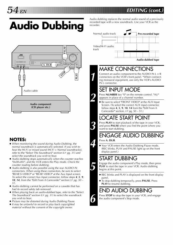
54 EN EDITING (cont.)
q
Audio dubbing replaces the normal audio sound of a previouslyrecorded tape with a new soundtrack. Use your VCR as therecorder.Audio Dubbing
MAKE CONNECTIONS
1 Connect an audio component to the AUDIO IN L + Rconnectors on the VCR's front panel. *When connect-ing monaural equipment, use only the VCR's AUDIOIN L connector.
SET INPUT MODE
2 Press NUMBER key "0" on the remote control. "AU"appears in place of a channel number.
● Be sure to select "FRONT VIDEO" at the AUX InputScreen. (To select the correct AUX input connector,follow steps 4, 5, 9, 10, 14 from the "Edit From ACamcorder" section, Z pg. 50 – 51.)
LOCATE START POINT
3 Press PLAY to start playback of the tape in your VCR,and press PAUSE when you find the point where youwant to start dubbing.
ENGAGE AUDIO DUBBING
4 Press A. DUB.
● Your VCR enters the Audio Dubbing Pause mode.(REC blinks, PLAY and PAUSE light up on the frontdisplay panel.)
START DUBBING
5 Engage the audio component's Play mode, then pressPLAY to start the tape in your VCR. Audio dubbingbegins at this point.
● REC blinks and PLAY is displayed on the front displaypanel.
● To stop dubbing temporarily, press PAUSE. PressPLAY to resume dubbing.
END AUDIO DUBBING
6 Press STOP to stop the tape in your VCR, and engagethe audio component's Stop mode.
Pre-recorded tape
Audio-dubbed tape
Normal audio track
Video/Hi-Fi audiotrack
Audio component(CD player etc.)
NOTES:● When monitoring the sound during Audio Dubbing, the
normal soundtrack is automatically selected. If you wish tohear the Hi-Fi or mixed sound (Hi-Fi + Normal soundtracks),refer to the "Select The Soundtrack" section (Z pg. 31) andselect the soundtrack you wish to hear.
● Audio dubbing stops automatically when the counter reaches"0H00M00S", and the VCR enters the Play mode. Check thecounter reading before dubbing.
● Audio dubbing is also possible using the rear AUDIO INconnectors. When using these connectors, be sure to select"REAR S-VIDEO" or "REAR VIDEO" at the Aux Input screen.To select the correct Aux Input connector, follow steps 4, 5, 9,10, 14, from the "Edit From A Camcorder" section Z pg. 50 –51.
● Audio dubbing cannot be performed on a cassette that hashad its record safety tab removed.
● When playing back an audio-dubbed tape, refer to the "SelectThe Soundtrack" section (Z pg. 31) to select the soundtrackyou wish to hear.
● Picture may be distorted during Audio Dubbing Pause.● It may be unlawful to record or play back copyrighted
material without the consent of the copyright owner.
STOP
PLA
Y
Audio cable
PAU
SEA. DUB
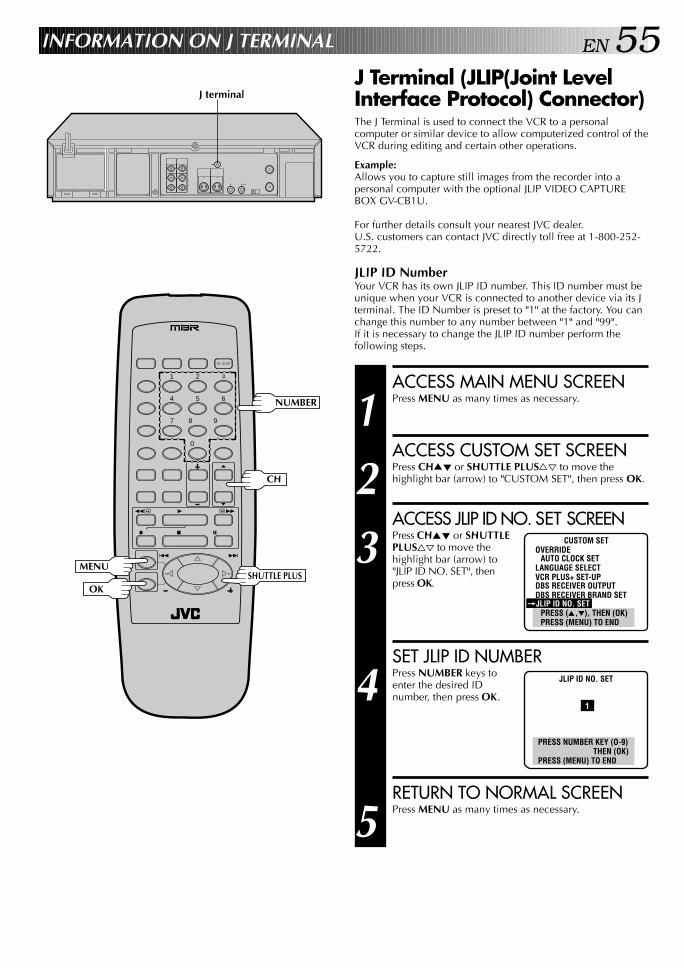
EN 55INFORMATION ON J TERMINAL
J Terminal (JLIP(Joint LevelInterface Protocol) Connector)The J Terminal is used to connect the VCR to a personalcomputer or similar device to allow computerized control of theVCR during editing and certain other operations.
Example:Allows you to capture still images from the recorder into apersonal computer with the optional JLIP VIDEO CAPTUREBOX GV-CB1U.
For further details consult your nearest JVC dealer.U.S. customers can contact JVC directly toll free at 1-800-252-5722.
JLIP ID NumberYour VCR has its own JLIP ID number. This ID number must beunique when your VCR is connected to another device via its Jterminal. The ID Number is preset to "1" at the factory. You canchange this number to any number between "1" and "99".If it is necessary to change the JLIP ID number perform thefollowing steps.
1 2 3
4 5 6
7 8
0
9
3
4 ¢
7 8
1 ¡
CH
MENUSHUTTLE PLUS
OK
J terminal
NUMBER
ACCESS MAIN MENU SCREEN
1 Press MENU as many times as necessary.
ACCESS CUSTOM SET SCREEN
2 Press CH5∞ or SHUTTLE PLUS%fi to move thehighlight bar (arrow) to "CUSTOM SET", then press OK.
ACCESS JLIP ID NO. SET SCREEN
3 Press CH5∞ or SHUTTLEPLUS%fi to move thehighlight bar (arrow) to"JLIP ID NO. SET", thenpress OK.
SET JLIP ID NUMBER
4 Press NUMBER keys toenter the desired IDnumber, then press OK.
RETURN TO NORMAL SCREEN
5 Press MENU as many times as necessary.
CUSTOM SETOVERRIDE
AUTO CLOCK SETLANGUAGE SELECTVCR PLUS+ SET-UPDBS RECEIVER OUTPUTDBS RECEIVER BRAND SET
=JLIP ID NO. SETPRESS (5,∞), THEN (OK)PRESS (MENU) TO END
JLIP ID NO. SET
1
PRESS NUMBER KEY (O-9)THEN (OK)
PRESS (MENU) TO END

56 EN SPECIAL FEATURES
1 2 3
4 5 6
7 8
0
9
3
4 ¢
7 8
1 ¡
POWER
TV/VCR
MBR SET
TV Multi-Brand RemoteControlThe VCR's remote control can control several functions on JVCremote control TVs and on the brands of remote control TVslisted below. *The default setting is JVC code 01.
TURN ON THE TV
1 Turn the power on using the TV's remote control.
SET TV BRAND CODE
2 Refer to the chart below. While holding down TV on theVCR's remote control, press MBR SET and enter your TV’sbrand code using the NUMBER keys, then press STOP.Follow the example shown below.
● Once you have set the remote control to operate theTV, you don’t have to repeat this step until youreplace your remote control’s batteries.
● PANASONIC has two codes. If the TV does notfunction with one code, try entering the other.
OPERATE TV
3 First, while holding down TV, press POWER on theremote to see if the TV’s power goes off as it should. If itdoes, try other operations.
● The POWER, TV/VCR, CH5∞, TV VOL +/– andNUMBER keys on the remote can all be used tooperate the TV. *For some brands of TV, you mustpress ENTER after having pressed the NUMBER keys.
● To operate your TV, while holding down TV, press thecorresponding button: POWER, TV/VCR, CH5∞,NUMBER keys (or ENTER). TV VOL +/– can be usedwithout holding down TV.
NOTE:Depending on the type of TV, there may be cases where someor all functions cannot be operated using the remote control.
TV
ENTER
TV BRAND NAME BRAND CODE
JVC 01
MAGNAVOX 02
MITSUBISHI 03
PANASONIC 04, 11
RCA 05
SHARP 06
SONY 07
TOSHIBA 08
ZENITH 09
HITACHI 10
SAMSUNG 12
SANYO 13
SEARS 13
(Ex.) To set remote control to RCA 05:
Release0 AUXTV 5 7STOPMBR SET
Holddown
Press in succession
NUMBER
CHTV VOL +/–
STO
P
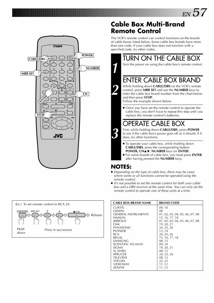
EN 57Cable Box Multi-BrandRemote ControlThe VCR's remote control can control functions on the brandsof cable boxes listed below. Some cable box brands have morethan one code. If your cable box does not function with aspecified code, try other codes.
TURN ON THE CABLE BOX
1 Turn the power on using the cable box’s remote control.
ENTER CABLE BOX BRAND
2 While holding down CABLE/DBS on the VCR's remotecontrol, press MBR SET and use the NUMBER keys toenter the cable box brand number from the chart belowand then press STOP.Follow the example shown below.
● Once you have set the remote control to operate thecable box, you don't have to repeat this step until youreplace the remote control's batteries.
OPERATE CABLE BOX
3 First, while holding down CABLE/DBS, press POWERto see if the cable box’s power goes off as it should. If itdoes, try other functions.
● To operate your cable box, while holding downCABLE/DBS, press the corresponding button:POWER, CH5∞, NUMBER keys (or ENTER).
● For some brands of cable box, you must press ENTERafter having pressed the NUMBER keys.
NOTES:● Depending on the type of cable box, there may be cases
where some or all functions cannot be operated using theremote control.
● It's not possible to set the remote control for both your cablebox and a DBS receiver at the same time. You can only set theremote control to operate one of these units at a time.
1 2 3
4 5 6
7 8
0
9
3
4 ¢
7 8
1 ¡
POWER
MBR SET
STOP
(Ex.) To set remote control to RCA 24:
ReleaseCABLE/DBS 2 4 7STOPMBR SET
Holddown
Press in succession
CABLE BOX BRAND NAME BRAND CODE
CURTIS 09, 10GEMINI 08GENERAL INSTRUMENTS 01, 02, 03, 04, 05, 06, 07, 08HAMLIN 15, 16, 17, 18JERROLD 01, 02, 03, 04, 05, 06, 07, 08OAK 19, 20, 21PANASONIC 24, 25, 26PIONEER 13, 14RCA 24, 25, 26REGAL 15, 16, 17, 18SAMSUNG 08, 13SCIENTIFIC ATLANTA 09, 10SIGMA 19, 20, 21SL MARX 08, 13SPRUCER 24, 25, 26TELEVIEW 08, 13TOCOM 22, 23VIDEOWAY 11, 12ZENITH 11, 12
CH
NUMBER
CABLE/DBS
ENTE
R

58 EN SPECIAL FEATURES (cont.)
DBS Receiver Multi-BrandRemote ControlThe VCR's remote control can control functions on the brandsof DBS (Direct Broadcast Satellite) receivers listed below.
TURN ON THE DBSRECEIVER
1 Turn the power on using the DBS receiver's remotecontrol.
ENTER DBS RECEIVERBRAND
2 While holding down CABLE/DBS on the VCR’s remotecontrol, press MBR SET and use the NUMBER keys toenter the DBS receiver brand number from the chartbelow and then press STOP.Follow the example shown below.
● Once you have set the remote control to operate theDBS receiver, you don't have to repeat this step untilyou replace the remote control's batteries.
OPERATE DBS RECEIVER
3 First, while holding down CABLE/DBS, press POWERto see if the DBS receiver's power goes off as it should.If it does, try other functions.
● To operate your DBS Receiver, while holding downCABLE/DBS, press the corresponding button:POWER, CH5∞, NUMBER keys (or ENTER).
● Depending on the DBS receiver you may have topress ENTER after having pressed the NUMBER keys.
NOTES:● Depending on the type of DBS receiver, there may be cases
where some or all functions cannot be operated using theremote control.
● It's not possible to operate a DBS receiver that is notequipped with a remote control sensor.
● Though ECHOSTAR has a number of different remote codes,this remote control is applicable only to one of those codespreset at the factory.
● It's not possible to set the remote control for both your DBSreceiver and a cable box at the same time. You can only setthe remote control to operate one of these units at a time.
1 2 3
4 5 6
7 8
0
9
3
4 ¢
7 8
1 ¡EN
TER
CABLE/DBSPOWER
NUMBER
CH
STOP
MBR SET
(Ex.) To set remote control to RCA (DSS):
0 AUX8 DAILY 7STOPMBR SETCABLE/DBS
Press in successionHolddown
Release
DBS BRAND NAME BRAND CODE
JVC (DISH Network) 91ECHOSTAR (DISH Network) 91
PRIMESTAR 90
SONY (DSS) 81RCA (DSS) 80
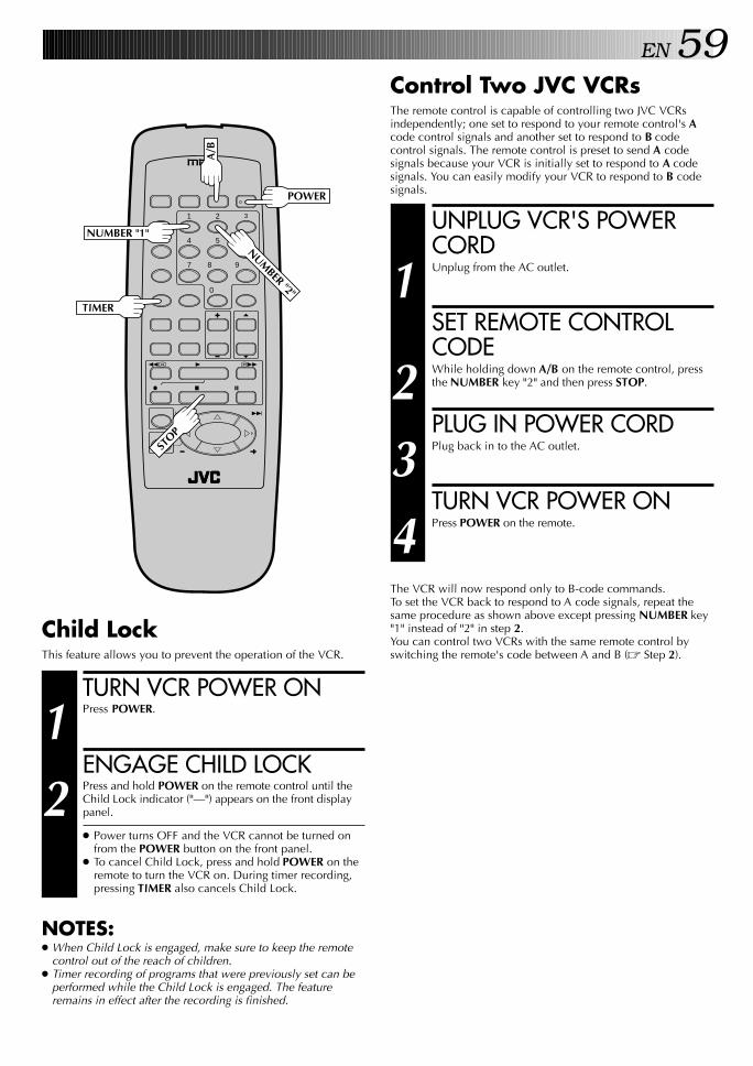
EN 59
1 2 3
4 5 6
7 8
0
9
3
4 ¢
7 8
1 ¡
POWERA
/B
NUMBER "1"
NUMBER "2"
UNPLUG VCR'S POWERCORD
1 Unplug from the AC outlet.
SET REMOTE CONTROLCODE
2 While holding down A/B on the remote control, pressthe NUMBER key "2" and then press STOP.
PLUG IN POWER CORD
3 Plug back in to the AC outlet.
TURN VCR POWER ON
4 Press POWER on the remote.
The VCR will now respond only to B-code commands.To set the VCR back to respond to A code signals, repeat thesame procedure as shown above except pressing NUMBER key"1" instead of "2" in step 2.You can control two VCRs with the same remote control byswitching the remote's code between A and B (Z Step 2).
Control Two JVC VCRsThe remote control is capable of controlling two JVC VCRsindependently; one set to respond to your remote control's Acode control signals and another set to respond to B codecontrol signals. The remote control is preset to send A codesignals because your VCR is initially set to respond to A codesignals. You can easily modify your VCR to respond to B codesignals.
STOP
TIMER
TURN VCR POWER ON
1 Press POWER.
ENGAGE CHILD LOCK
2 Press and hold POWER on the remote control until theChild Lock indicator ("—") appears on the front displaypanel.
● Power turns OFF and the VCR cannot be turned onfrom the POWER button on the front panel.
● To cancel Child Lock, press and hold POWER on theremote to turn the VCR on. During timer recording,pressing TIMER also cancels Child Lock.
NOTES:● When Child Lock is engaged, make sure to keep the remote
control out of the reach of children.● Timer recording of programs that were previously set can be
performed while the Child Lock is engaged. The featureremains in effect after the recording is finished.
Child LockThis feature allows you to prevent the operation of the VCR.
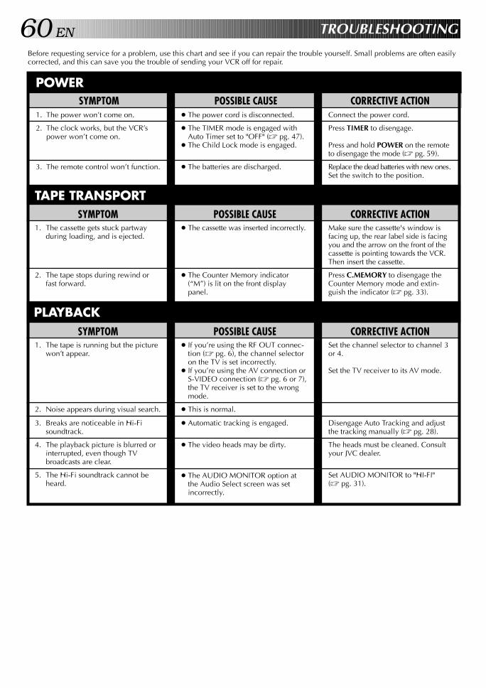
60 EN TROUBLESHOOTING
Before requesting service for a problem, use this chart and see if you can repair the trouble yourself. Small problems are often easilycorrected, and this can save you the trouble of sending your VCR off for repair.
POSSIBLE CAUSE● The power cord is disconnected.
● The TIMER mode is engaged withAuto Timer set to "OFF" (Z pg. 47).
● The Child Lock mode is engaged.
● The batteries are discharged.
SYMPTOM1. The power won’t come on.
2. The clock works, but the VCR’spower won’t come on.
3. The remote control won’t function.
CORRECTIVE ACTIONConnect the power cord.
Press TIMER to disengage.
Press and hold POWER on the remoteto disengage the mode (Z pg. 59).
Replace the dead batteries with new ones.Set the switch to the position.
SYMPTOM1. The cassette gets stuck partway
during loading, and is ejected.
2. The tape stops during rewind orfast forward.
CORRECTIVE ACTIONMake sure the cassette's window isfacing up, the rear label side is facingyou and the arrow on the front of thecassette is pointing towards the VCR.Then insert the cassette.
Press C.MEMORY to disengage theCounter Memory mode and extin-guish the indicator (Z pg. 33).
SYMPTOM1. The tape is running but the picture
won’t appear.
2. Noise appears during visual search.
3. Breaks are noticeable in Hi-Fisoundtrack.
4. The playback picture is blurred orinterrupted, even though TVbroadcasts are clear.
5. The Hi-Fi soundtrack cannot beheard.
POSSIBLE CAUSE● If you’re using the RF OUT connec-
tion (Z pg. 6), the channel selectoron the TV is set incorrectly.
● If you’re using the AV connection orS-VIDEO connection (Z pg. 6 or 7),the TV receiver is set to the wrongmode.
● This is normal.
● Automatic tracking is engaged.
● The video heads may be dirty.
● The AUDIO MONITOR option atthe Audio Select screen was setincorrectly.
CORRECTIVE ACTIONSet the channel selector to channel 3or 4.
Set the TV receiver to its AV mode.
Disengage Auto Tracking and adjustthe tracking manually (Z pg. 28).
The heads must be cleaned. Consultyour JVC dealer.
Set AUDIO MONITOR to "HI-FI"(Z pg. 31).
POSSIBLE CAUSE● The cassette was inserted incorrectly.
● The Counter Memory indicator(“M”) is lit on the front displaypanel.
PLAYBACK
TAPE TRANSPORT
POWER
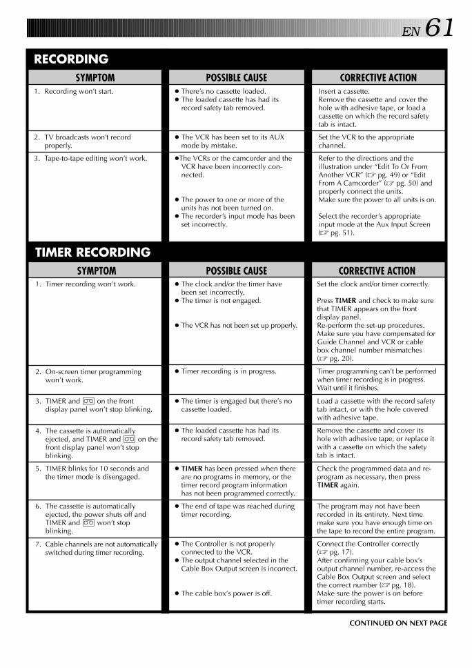
EN 61
CORRECTIVE ACTIONInsert a cassette.Remove the cassette and cover thehole with adhesive tape, or load acassette on which the record safetytab is intact.
Set the VCR to the appropriatechannel.
Refer to the directions and theillustration under “Edit To Or FromAnother VCR” (Z pg. 49) or “EditFrom A Camcorder” (Z pg. 50) andproperly connect the units.Make sure the power to all units is on.
Select the recorder’s appropriateinput mode at the Aux Input Screen(Z pg. 51).
POSSIBLE CAUSE● There’s no cassette loaded.● The loaded cassette has had its
record safety tab removed.
● The VCR has been set to its AUXmode by mistake.
●The VCRs or the camcorder and theVCR have been incorrectly con-nected.
● The power to one or more of theunits has not been turned on.
● The recorder’s input mode has beenset incorrectly.
SYMPTOM1. Recording won’t start.
2. TV broadcasts won’t recordproperly.
3. Tape-to-tape editing won’t work.
RECORDING
TIMER RECORDINGCORRECTIVE ACTION
Set the clock and/or timer correctly.
Press TIMER and check to make surethat TIMER appears on the frontdisplay panel.Re-perform the set-up procedures.Make sure you have compensated forGuide Channel and VCR or cablebox channel number mismatches(Z pg. 20).
Timer programming can’t be performedwhen timer recording is in progress.Wait until it finishes.
Load a cassette with the record safetytab intact, or with the hole coveredwith adhesive tape.
Remove the cassette and cover itshole with adhesive tape, or replace itwith a cassette on which the safetytab is intact.
Check the programmed data and re-program as necessary, then pressTIMER again.
The program may not have beenrecorded in its entirety. Next timemake sure you have enough time onthe tape to record the entire program.
Connect the Controller correctly(Z pg. 17).After confirming your cable box’soutput channel number, re-access theCable Box Output screen and selectthe correct number (Z pg. 18).Make sure the power is on beforetimer recording starts.
SYMPTOM1. Timer recording won’t work.
2. On-screen timer programmingwon’t work.
3. TIMER and ] on the frontdisplay panel won’t stop blinking.
4. The cassette is automaticallyejected, and TIMER and ] on thefront display panel won’t stopblinking.
5. TIMER blinks for 10 seconds andthe timer mode is disengaged.
6. The cassette is automaticallyejected, the power shuts off andTIMER and ] won’t stopblinking.
7. Cable channels are not automaticallyswitched during timer recording.
POSSIBLE CAUSE● The clock and/or the timer have
been set incorrectly.● The timer is not engaged.
● The VCR has not been set up properly.
● Timer recording is in progress.
● The timer is engaged but there’s nocassette loaded.
● The loaded cassette has had itsrecord safety tab removed.
● TIMER has been pressed when thereare no programs in memory, or thetimer record program informationhas not been programmed correctly.
● The end of tape was reached duringtimer recording.
● The Controller is not properlyconnected to the VCR.
● The output channel selected in theCable Box Output screen is incorrect.
● The cable box’s power is off.
CONTINUED ON NEXT PAGE

62 EN
8. Satellite channels are not automati-cally switched during timerrecording.
9. Timer recording begins as sched-uled, but the channel is alwaysincorrect.
10.We moved, and now VCR Plus+doesn’t work properly.
11.“PROGRAM FULL” is displayed onthe VCR Plus+ screen.
Connect the Controller correctly(Z pg. 22).After confirming your DBS receiver’soutput channel number, re-access theDBS Receiver Output screen andselect the correct number (Z pg. 23).Set the correct DBS Receiver brandcode (Z pg. 24).Make sure the power is on beforetimer recording starts.
Set "CABLE BOX OUTPUT" to "OFF"(Z pg. 18).
Re-perform the VCR Plus+ setupprocedure (Z pg. 20).
Wait until a space in memory clears,or cancel unnecessary programinformation (Z pg. 46).
● The Controller is not properlyconnected to the VCR.
● The output channel selected in theDBS Receiver Output screen isincorrect.
● The VCR is not set correctly tocontrol the DBS Receiver
● The DBS receiver’s power is off.
● Even though you don't use anexternal Cable Box, "CABLE BOXOUTPUT" is set to "ON".
● The receivable stations in the new areaare received on different channels thanthose in the previous area.
● All 8 programs of the VCR’s timermemory are used.
OTHER PROBLEMSCORRECTIVE ACTION
If you need the skipped channels,restore them (Z pg. 16).
Press PAUSE to pause the recording,change channels, then press PLAY toresume recording.
Re-set the remote control to thecorrect brand (Z pg. 56 or 57 or 58).
Select a different Host Channel duringthe Semi-Auto setting procedure(Z pg. 12), or perform the Manualsetting procedure (Z pg. 13).
SYMPTOM1. When scanning channels, some of
them are skipped over.
2. The channel can’t be changed.
3. The remote control won’t operatemy TV or cable box or DBS receiver.
4. Even though Auto or Semi-Autoclock setting has been selected, theclock is incorrect.
POSSIBLE CAUSE● Those channels have been preset to
be skipped.
● Recording is in progress.
● The remote control brand setting isincorrect.
● The clock setting data received fromthe Host Channel is incorrect.
ATTENTION:This VCR contains microcomputers. External electronic noise or interference can cause microcomputer to malfunction. If theVCR does not operate correctly switch its power off and unplug the power cord from the AC supply. Wait for a while and thenplug the power back in. Eject and check the condition of the cassette. If everything appears normal resume operating the VCR asusual.
TROUBLESHOOTING (cont.)

EN 63QUESTIONS AND ANSWERS
PLAYBACKQ. What happens if the end of the tape is reached
during playback or search?
○ ○ ○ ○ ○ ○ ○ ○ ○ ○ ○ ○ ○ ○ ○ ○ ○ ○ ○ ○ ○ ○ ○ ○ ○ ○ ○ ○
A. The tape is automatically rewound to the beginning.
Q. Can the VCR indefinitely remain in the still mode?A. No. It stops automatically after 5 minutes to protect
○ ○ ○ ○ ○ ○ ○ ○ ○ ○ ○ ○ ○ ○ ○ ○ ○ ○ ○ ○ ○ ○ ○ ○ ○ ○ ○ ○
the heads.
Q. During search, slow, still and frame-by-frameplayback, I can’t hear any audio. What’s theproblem?
○ ○ ○ ○ ○ ○ ○ ○ ○ ○ ○ ○ ○ ○ ○ ○ ○ ○ ○ ○ ○ ○ ○ ○ ○ ○ ○ ○
A. This is normal.
Q. During search, still and frame-by-frame playback,the picture is intermittent. What’s the cause?
A. Picture loss occurs when these types of playback areattempted with a tape recorded in LP mode. PressingPLAY to return to normal playback will restore the
○ ○ ○ ○ ○ ○ ○ ○ ○ ○ ○ ○ ○ ○ ○ ○ ○ ○ ○ ○ ○ ○ ○ ○ ○ ○ ○ ○
picture.
Q. When returning from multi-speed search to normalplayback, the picture is disturbed. Should I beconcerned about this?
○ ○ ○ ○ ○ ○ ○ ○ ○ ○ ○ ○ ○ ○ ○ ○ ○ ○ ○ ○ ○ ○ ○ ○ ○ ○ ○ ○
A. No, it is normal.
Q. Noise bars appear during multi-speed search. What’sthe problem?
○ ○ ○ ○ ○ ○ ○ ○ ○ ○ ○ ○ ○ ○ ○ ○ ○ ○ ○ ○ ○ ○ ○ ○ ○ ○ ○ ○
A. This is normal.
Q. When playing back programs that have been timer-recorded with consecutive times (such one programfrom 8:00 to 9:00 and another one from 9:00 to10:00), the picture and sound become momentarilydistorted at the point where the first program endsand the second program begins. Is this amalfunction?
○ ○ ○ ○ ○ ○ ○ ○ ○ ○ ○ ○ ○ ○ ○ ○ ○ ○ ○ ○ ○ ○ ○ ○ ○ ○ ○ ○
A. No. This is normal.
Q. Other than preventing further recording, what effectdoes removing the safety tab have?
○ ○ ○ ○ ○ ○ ○ ○ ○ ○ ○ ○ ○ ○ ○ ○ ○ ○ ○ ○ ○ ○ ○ ○ ○ ○ ○ ○
A. It disables marking of index codes.
Q. Sometimes, during Index Search, the VCR can’t findthe program I want to see. Why not?
○ ○ ○ ○ ○ ○ ○ ○ ○ ○ ○ ○ ○ ○ ○ ○ ○ ○ ○ ○ ○ ○ ○ ○ ○ ○ ○ ○
A. There may be index codes too close together.
Q. During playback, on-screen operational indicatorssometimes jitter. Why does this happen?
A. If the condition of the tape being played back is notgood, jittering of the video (including on-screenindicators) may occur.
RECORDINGQ. When I pause and then resume a recording, the end
of the recording before the pause is overlapped bythe new recording. Why does this happen?
A. This is normal. It reduces distortion at the pause and
○ ○ ○ ○ ○ ○ ○ ○ ○ ○ ○ ○ ○ ○ ○ ○ ○ ○ ○ ○ ○ ○ ○ ○ ○ ○ ○ ○
resume points.
Q. Can the VCR indefinitely remain in the Record-Pausemode?
A. No. The VCR automatically goes to its Stop modeafter 5 minutes to protect the heads. When pausedduring Instant Timer Recording (ITR), the VCR shuts
○ ○ ○ ○ ○ ○ ○ ○ ○ ○ ○ ○ ○ ○ ○ ○ ○ ○ ○ ○ ○ ○ ○ ○ ○ ○ ○ ○
off automatically after 5 minutes.
Q. What happens if the tape runs out during recording?A. The VCR automatically rewinds it to the beginning.
TIMER RECORDINGQ. REC and TIMER remain lit on the front display panel.
Is there a problem?A. No. This is a normal condition for a timer recording
○ ○ ○ ○ ○ ○ ○ ○ ○ ○ ○ ○ ○ ○ ○ ○ ○ ○ ○ ○ ○ ○ ○ ○ ○ ○ ○ ○
in progress.
Q. Can I program the timer while I’m watching a tapeor a TV broadcast?
A. Yes, but while you are setting the timer you won't seethe tape's or broadcast program's picture as it isreplaced by the on-screen menu. The audio from thetape or broadcast program will be present during thesetting of the timer.
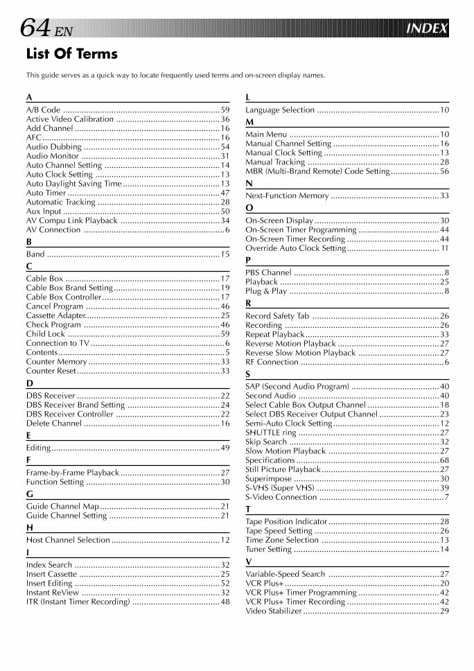
64 EN INDEX
List Of TermsThis guide serves as a quick way to locate frequently used terms and on-screen display names.
AA/B Code ....................................................................59Active Video Calibration .............................................36Add Channel ...............................................................16AFC.............................................................................16Audio Dubbing ...........................................................54Audio Monitor ............................................................31Auto Channel Setting ..................................................14Auto Clock Setting ......................................................13Auto Daylight Saving Time ..........................................13Auto Timer ..................................................................47Automatic Tracking .....................................................28Aux Input ....................................................................50AV Compu Link Playback ...........................................34AV Connection .............................................................6
BBand ...........................................................................15
CCable Box ...................................................................17Cable Box Brand Setting..............................................19Cable Box Controller ...................................................17Cancel Program ..........................................................46Cassette Adapter.................................... ......................25Check Program ...........................................................46Child Lock ..................................................................59Connection to TV ..........................................................6Contents ........................................................................5Counter Memory .........................................................33Counter Reset ..............................................................33
DDBS Receiver ..............................................................22DBS Receiver Brand Setting ........................................24DBS Receiver Controller .............................................22Delete Channel ...........................................................16
EEditing.........................................................................49
FFrame-by-Frame Playback ...........................................27Function Setting ..........................................................30
GGuide Channel Map....................................................21Guide Channel Setting ................................................21
HHost Channel Selection ...............................................12
IIndex Search ...............................................................32Insert Cassette .............................................................25Insert Editing ...............................................................52Instant ReView ............................................................32ITR (Instant Timer Recording) ......................................48
LLanguage Selection .....................................................10
MMain Menu .................................................................10Manual Channel Setting ..............................................16Manual Clock Setting ..................................................13Manual Tracking .........................................................28MBR (Multi-Brand Remote) Code Setting.....................56
NNext-Function Memory ...............................................33
OOn-Screen Display ......................................................30On-Screen Timer Programming ...................................44On-Screen Timer Recording ........................................44Override Auto Clock Setting........................................ 11
PPBS Channel .................................................................8Playback .....................................................................25Plug & Play ...................................................................8
RRecord Safety Tab .......................................................26Recording ...................................................................26Repeat Playback..........................................................33Reverse Motion Playback ............................................27Reverse Slow Motion Playback ...................................27RF Connection ..............................................................6
SSAP (Second Audio Program) ......................................40Second Audio .............................................................40Select Cable Box Output Channel ...............................18Select DBS Receiver Output Channel ..........................23Semi-Auto Clock Setting..............................................12SHUTTLE ring .............................................................27Skip Search .................................................................32Slow Motion Playback ................................................27Specifications ..............................................................68Still Picture Playback...................................................27Superimpose ...............................................................30S-VHS (Super VHS) .....................................................39S-Video Connection ......................................................7
TTape Position Indicator ................................................28Tape Speed Setting ......................................................26Time Zone Selection ...................................................13Tuner Setting ...............................................................14
VVariable-Speed Search ................................................27VCR Plus+...................................................................20VCR Plus+ Timer Programming ...................................42VCR Plus+ Timer Recording ........................................42Video Stabilizer ...........................................................29
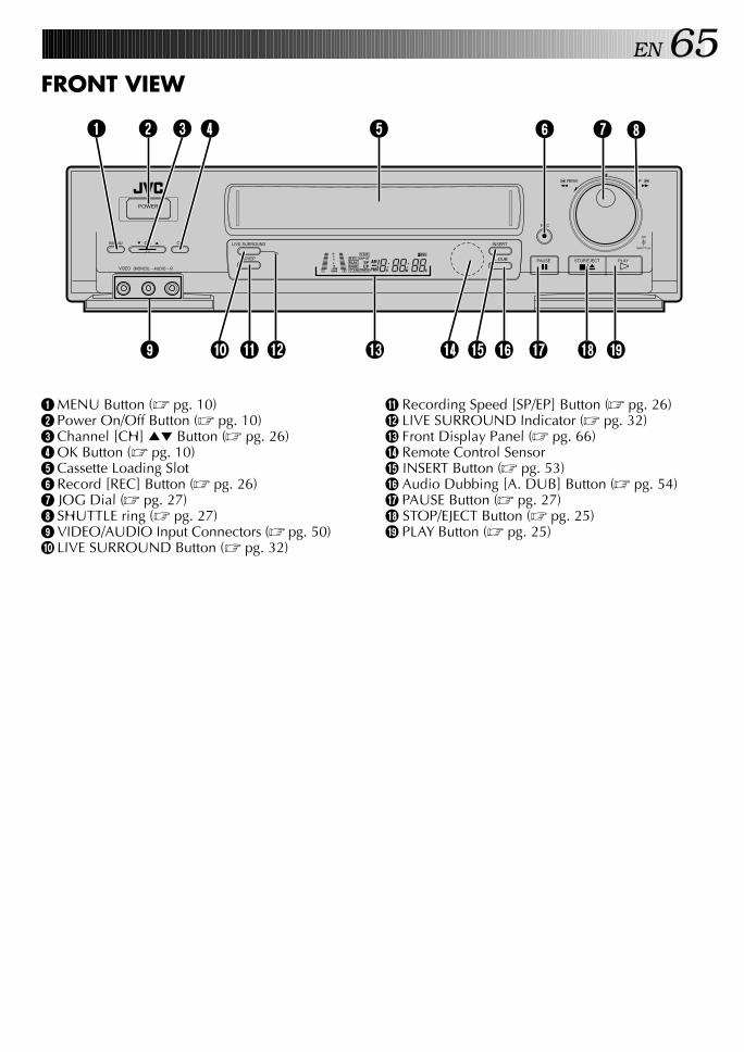
EN 65FRONT VIEW
1 MENU Button (Z pg. 10)2 Power On/Off Button (Z pg. 10)3 Channel [CH] 5∞ Button (Z pg. 26)4 OK Button (Z pg. 10)5 Cassette Loading Slot6 Record [REC] Button (Z pg. 26)7 JOG Dial (Z pg. 27)8 SHUTTLE ring (Z pg. 27)9 VIDEO/AUDIO Input Connectors (Z pg. 50)0 LIVE SURROUND Button (Z pg. 32)
! Recording Speed [SP/EP] Button (Z pg. 26)@ LIVE SURROUND Indicator (Z pg. 32)# Front Display Panel (Z pg. 66)$ Remote Control Sensor% INSERT Button (Z pg. 53)^ Audio Dubbing [A. DUB] Button (Z pg. 54)& PAUSE Button (Z pg. 27)* STOP/EJECT Button (Z pg. 25)( PLAY Button (Z pg. 25)
INSERT
PAUSE
REC
STOP/EJECT PLAY
q
POWER
JOG
SHUTTLE
VIDEO (MONO)L – AUDIO – R
SP/EP
MENU CH OK
A. DUB
LIVE SURROUND
REW FF
H M S
SP AM
PM
R E CPLAY
SAP ST
TIMERPAUSE
M
V C R+840
610
–20dBNORML R
31 2
(*&^%$#! @0
54 6 7 8
9

66 EN INDEX (cont.)
REAR VIEW
1 Power Cord (Z pg. 6)2 VIDEO/AUDIO Output Connectors (Z pg. 49)3 VIDEO/AUDIO Input Connectors (Z pg. 49)4 J Terminal [JLIP (Joint Level Interface Protocol)
Connector] (Z pg. 55)5 ANTENNA IN Connector (Z pg. 6)6 S-Video (S-VHS) Output Connector (Z pg. 49)
7 S-Video (S-VHS) Input Connector (Z pg. 49)8 PAUSE/SPECIAL FUNCTION Connector
● Remote PAUSE Connector (Z pg. 50)● AV COMPU-LINK Connector (Z pg. 34)
9 CABLE BOX Controller Connector (Z pg. 17, 22)0 Channel 3/4 Switch (Z pg. 6)! TV OUT Connector (Z pg. 6)
ANTENNAOUT
CH3
PAUSE/ SPECIAL
FUNCTION
IN
OUT S VIDEO
IN S VIDEO
VIDEO
AUDIO
L(MONO)
R
CABLE BOX
CH4
IN
VHF / UHF
OUTTV
JLIP
1 2
6 7 8 9 !0
3 4 5
FRONT DISPLAY PANEL
H M S
SP AM
PM
R E CPLAY
SAP ST
TIMERPAUSE
M
V C R+840
610
–20dBNORML R
$ %! #@ ^ 9
721 64 83 5
0
1 Audio Level meter (Z pg. 41)2 Play Mode Indicator3 Recording Mode Indicator
Instant Timer Recording Indicator (Z pg. 48)4 VCR Mode Indicator (Z pg. 38)5 Multi-Channel TV Sound Indicators (Z pg. 40)6 AM/PM Indicators (Z pg. 8)7 Clock Display (Z pg. 8)8 S-VHS Indicator (Z pg. 39)
9 Audio Output mode indicator (Z pg. 31)0 Pause Mode Indicator! “Cassette Loaded” Mark@ Counter Memory Mark (Z pg. 33)# Tape Speed Indicators (Z pg. 26)$ Timer Mode Indicator% Child Lock Indicator (Z pg. 59)^ Channel Display [“AU” for AUX mode]
Counter Display (Z pg. 8)

EN 67REMOTE CONTROL
1 CABLE/DBS Button (Z pg. 57, 58)2 TV Button (Z pg. 56)3 TV/VCR Button (Z pg. 38)4 MBR SET Button (Z pg. 56)
LIVE SURROUND Button (Z pg. 32)5 DISPLAY Button (Z pg. 33)6 ENTER Button (Z pg. 26)
On-Screen Display [OSD] Button (Z pg. 30)7 TIMER Button (Z pg. 43, 45)8 Counter [C.] MEMORY Button (Z pg. 33)
ADD Button (Z pg. 16)9 CANCEL Button (Z pg. 46)
Channel [CH] SKIP Button (Z pg. 16)Counter [C.] RESET Button (Z pg. 33)
0 Instant REVIEW Button (Z pg. 32)! SKIP SEARCH Button (Z pg. 32)@ Rewind [REW] Button (Z pg. 25)# PLAY Button (Z pg. 25)$ Record [REC] Button (Z pg. 26)% MENU Button (Z pg. 10)^ OK Button (Z pg. 10)& A/B Code Button (Z pg. 59)* POWER On/Off Button (Z pg. 10)( DAILY Timer Recording Button (Z pg. 42, 45)) NUMBER Buttons (Z pg. 26, 42)q WEEKLY Timer Recording Button (Z pg. 42, 45)w "AUX" Mode Select Button (Z pg. 50)e Recording Speed [SP/EP] Button (Z pg. 26)r TV Volume [VOL] +/– Button (Z pg. 56)t Channel [CH] 5∞ Button (Z pg. 26)y Fast-Foward [FF] Button (Z pg. 25)u STOP Button (Z pg. 25)i PAUSE Button (Z pg. 27)o SHUTTLE PLUS Button (Z pg. 10, 27)
A/BTV CABLE/DBS
TV, CABLE / DBS operation – Press and hold TV CABLE/DBS button, then press POWER, CH 5/∞, TV/VCR, 0 – 9, ENTER
TV/VCR 1 2 3
4 5 6
7 8 DAILY
0 AUX
9 WEEKLY
LIVE SURROUND
MBR SET DISPLAY
TIMER
CANCEL C.MEMORY
SKIP SEARCHC.RESET/CH.SKIP ADD
OSD
ENTER SP/EP
TV VOL CH
MENU
SHUTTLE PLUS
OK
¶REC
4 ¢
7STOP 8PAUSE
POWER
3PLAY1 FF ¡REW
yu
i
o
123456
87
90
@!
$#
%^
&*)
ert
(qw
Installing Batteries
1 Open the battery compartment cover.2 Insert 2 "AA"-size batteries (provided) in the direction
indicated under the battery cover.3 Replace the cover.
How To UseThe remote control can operate most of your VCR'sfunctions.1 Point the remote control toward the sensor window.2 Press the appropriate operation button.3 The maximum operating distance of the remote control
is about 8 m.
NOTES:● This remote control can also operate various brands of
TVs, Cable Boxes and DBS Receivers. For instructions, Zpg. 56 – 58.
● If the remote control doesn't work properly, remove itsbatteries, wait a short time, replace the batteries and thentry again.
The glow-in-the-dark buttons shown in white on theillustration above are helpful when using the remote controlin darkened rooms.
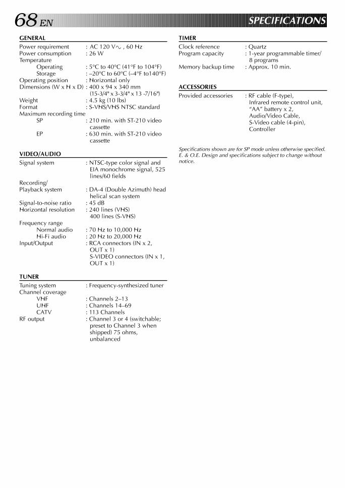
68 EN
GENERALPower requirement : AC 120 V` , 60 HzPower consumption : 26 WTemperature
Operating : 5°C to 40°C (41°F to 104°F)Storage : –20°C to 60°C (–4°F to140°F)
Operating position : Horizontal onlyDimensions (W x H x D) : 400 x 94 x 340 mm
(15-3/4" x 3-3/4" x 13 -7/16")Weight : 4.5 kg (10 lbs)Format : S-VHS/VHS NTSC standardMaximum recording time
SP : 210 min. with ST-210 videocassette
EP : 630 min. with ST-210 videocassette
VIDEO/AUDIOSignal system : NTSC-type color signal and
EIA monochrome signal, 525lines/60 fields
Recording/Playback system : DA-4 (Double Azimuth) head
helical scan systemSignal-to-noise ratio : 45 dBHorizontal resolution : 240 lines (VHS)
400 lines (S-VHS)Frequency range
Normal audio : 70 Hz to 10,000 HzHi-Fi audio : 20 Hz to 20,000 Hz
Input/Output : RCA connectors (IN x 2,OUT x 1)S-VIDEO connectors (IN x 1,OUT x 1)
TUNERTuning system : Frequency-synthesized tunerChannel coverage
VHF : Channels 2–13UHF : Channels 14–69CATV : 113 Channels
RF output : Channel 3 or 4 (switchable;preset to Channel 3 whenshipped) 75 ohms,unbalanced
SPECIFICATIONS
TIMERClock reference : QuartzProgram capacity : 1-year programmable timer/
8 programsMemory backup time : Approx. 10 min.
ACCESSORIESProvided accessories : RF cable (F-type),
Infrared remote control unit,“AA” battery x 2,Audio/Video Cable,S-Video cable (4-pin),Controller
Specifications shown are for SP mode unless otherwise specified.E. & O.E. Design and specifications subject to change withoutnotice.
EN 69HOW TO LOCATE YOUR JVC SERVICE CENTER
TOLL FREE: 1-800-252-5722
JVC SERVICE & ENGINEERINGCOMPANY OF AMERICA
DIVISION OF US JVC CORP.
FACTORY SERVICE CENTER LOCATIONS
If you ship the product...
ACCESSORIES
107 Little Falls Road 1500 Lakes Parkway 705 Enterprise StreetFairfield, NJ 07004-2105 Lawrenceville, GA 30243-5857 Aurora, IL 60504-8135(973) 808-9279 (770) 339-2522 (630) 851-7855
5665 Corporate Avenue 10700 Hammerly Boulevard, Suite 110 2969 Mapunapuna Place, Suite 101Cypress, CA 90630-4727 Houston, TX 77043-2310 Honolulu, HI 96819-2000(714) 229-8011 (713) 935-9331 (808) 833-5828
230 Eliot Street 8192 W State Road 84 890 Dubuque AvenueAshland, MA 01721-2377 Davie, FL 33324-4611 South San Francisco, CA 94080-1804(508) 881-5923 (954) 472-1960 (415) 871-2666
Sophisticated electronic products may require occasional service. Just as quality is a keyword in the engineering and productionof the wide array of JVC products, service is the key to maintaining the high level performance for which JVC is world famous. TheJVC service and engineering organization stands behind our products.
NATIONAL HEADQUARTERSJVC SERVICE & ENGINEERING COMPANY OF AMERICA
DIVISION OF US JVC CORP.107 Little Falls Road
Fairfield, NJ 07004-2105
Pack your JVC unit in the original carton or one of equivalentsize and strength. Enclose, with the unit, a letter stating theproblem or symptom that exists and also a copy of the receiptor bill of sale you received when you purchased your JVCunit. Print your home return address on the outside and theinside of the carton. Send to the appropriate JVC FactoryService Center as listed above.
To purchase accessories for your JVC product, you maycontact your local JVC Dealer.Or from the 48 Continental United States call toll free:1-800-882-2345.
Dear customer:In order to receive the most satisfaction from your purchase, read the instruction booklet before operating the unit. In the eventthat repair is necessary, or for the address nearest your location, please refer to the factory service center list below or within theContinental United States, call 1-800-252-5722 for your authorized servicer. Remember to retain your Bill of Sale for WarrantyService.
— JVC
CAUTIONTo prevent electrical shock, do not open the cabinet. No userserviceable parts inside.Refer servicing to qualified service personnel.
Don't service it yourself.
FOR SERVICING (Only in U.S.A.)
70 EN
LIMITED WARRANTY CONSUMER VIDEO 1-90
JVC COMPANY OF AMERICA warrants this product and all parts thereof, except as set forth below ONLY TO THE ORIGINALPURCHASER AT RETAIL to be FREE FROM DEFECTIVE MATERIALS AND WORKMANSHIP from the date of original retailpurchase for the period as shown below. ("The Warranty Period")
THIS LIMITED WARRANTY IS VALID ONLY IN THE FIFTY (50) UNITED STATES, THE DISTRICT OF COLUMBIA AND INCOMMONWEALTH OF PUERTO RICO.
WHAT WE WILL DO:If this product is found to be defective, JVC will repair or replace defective parts at no charge to the original owner. Such repairand replacement services shall be rendered by JVC during normal business hours at JVC authorized service centers. Partsused for replacement are warranted only for the remainder of the Warranty Period. All products and parts thereof may bebrought to a JVC authorized service center on a carry-in basis except for Television sets having a screen size 25 inches andabove which are covered on an in-home basis.
WHAT YOU MUST DO FOR WARRANTY SERVICE:Return your product to a JVC authorized service center with a copy of your bill of sale. For your nearest JVC authorizedservice center, please call toll free: (800) 252-5722.If service is not available locally, box the product carefully, preferably in the original carton, and ship, insured, with a copy ofyour bill of sale plus a letter of explanation of the problem to the nearest JVC Factory Service Center, the name and locationof which will be given to you by the toll-free number.
If you have any questions concerning your JVC Product, please contact our Customer Relations Department.
WHAT IS NOT COVERED:This limited warranty provided by JVC does not cover:1. Products which have been subject to abuse, accident, alteration, modification, tampering, negligence, misuse, faulty
installation, lack of reasonable care, or if repaired or serviced by anyone other than a service facility authorized by JVC torender such service, or if affixed to any attachment not provided with the products, or if the model or serial number has beenaltered, tampered with, defaced or removed;
2. Initial installation and installation and removal for repair;3. Operational adjustments covered in the Owner's Manual, normal maintenance, video and audio head cleaning;4. Damage that occurs in shipment, due to act of God, and cosmetic damage;5. Signal reception problems and failures due to line power surge;6. Video Pick-up Tubes/CCD Image Sensor, Cartridge, Stylus (Needle) are covered for 90 days from the date of purchase;7. Accessories;8. Batteries (except that Rechargeable Batteries are covered for 90 days from the date of purchase); from the date of purchase);
There are no other express warranties except as listed above.
THE DURATION OF ANY IMPLIED WARRANTIES INCLUDING THE IMPLIED WARRANTY OF MERCHANTABILITY, ISLIMITED TO THE DURATION OF THE EXPRESS WARRANTY HEREIN.
JVC SHALL NOT BE LIABLE FOR THE LOSS OF USE OF THE PRODUCT, INCONVENIENCE, LOSS OR ANY OTHERDAMAGES, WHETHER DIRECT, INCIDENTAL OR CONSEQUENTIAL (INCLUDING, WITHOUT LIMITATION, DAMAGE TOTAPES, RECORDS OR DISCS) RESULTING FROM THE USE OF THIS PRODUCT, OR ARISING OUT OF ANY BREACHOF THIS WARRANTY. ALL EXPRESS AND IMPLIED WARRANTIES, INCLUDING THE WARRANTIES OFMERCHANTABILITY AND FITNESS FOR PARTICULAR PURPOSE, ARE LIMITED TO THE WARRANTY PERIOD SETFORTH ABOVE.
Some states do not allow the exclusion of incidental or consequential dameges or limitations on how long an implied warrantylasts, so these limitations or exclusions may not apply to you. This warranty gives you specific legal rights and you may alsohave other rights which vary from state to state.
JVC COMPANY OF AMERICA 41 Slater DriveDIVISION OF US JVC CORP. Elmwood Park, New Jersey 07407
REFURBISHED PRODUCTS CARRY A SEPARATE WARRANTY, THIS WARRANTY DOES NOT APPLY. FOR DETAILS OFREFURBISHED PRODUCT WARRANTY, PLEASE REFER TO THE REFURBISHED PRODUCT WARRANTY INFORMATIONPACKAGED WITH EACH REFURBISHED PRODUCT.
For customer use:Enter below the Model No. and Serial No. which is located either on the rear, bottom or side of the cabinet. Retain this information for futurereference.
Model No.: Serial No.:
Purchase date: Name of dealer:
PARTS LABOR1 YR 90 DAYS
WARRANTY (Only in U.S.A.)

EN 71MEMO

HR
-S5
40
0U
COPYRIGHT © 1997 VICTOR COMPANY OF JAPAN, LTD. U/U(C) Printed in Malaysia 0797HOV*UN*PJ
JVC COMPANY OF AMERICA DIVISION OF US JVC CORP.
41 Slater Drive, Elmwood Park, N.J. 07407
JVC CANADA INC. 21 Finchdene Square, Scarborough Ontario M1X 1A7