VectorWorks 10.5 Tutorials
102
VectorWorks Tutorials Welcome to the VectorWorks tutorials. These tutorials present detailed explanations for procedures, tools, and commands in VectorWorks 3D Power Pack TM and VectorWorks Mechanical. The 3D Power Pack commands are included with VectorWorks 9.5.1 and later to provide significantly expanded NURBS (Non Uniform Rational B-Splines) functionality. New and improved functionality has been introduced with VectorWorks 10.5. VectorWorks Mechanical, an Industry Series product, is a professional design and drafting package. Using VectorWorks technology, Mechanical provides the engineering professional with the tools necessary for creating an entire project, from design to finished drawings. To navigate to the tutorial you are interested in, select it from the table of contents on the left.
Transcript of VectorWorks 10.5 Tutorials
VectorWorks Tutorials
Welcome to the VectorWorks tutorials. These tutorials present detailed explanations for procedures, tools, and commands in VectorWorks 3D Power PackTM and VectorWorks Mechanical. The 3D Power Pack commands are included with VectorWorks 9.5.1 and later to provide significantly expanded NURBS (Non Uniform Rational B-Splines) functionality. New and improved functionality has been introduced with VectorWorks 10.5.VectorWorks Mechanical, an Industry Series product, is a professional design and drafting package. Using VectorWorks technology, Mechanical provides the engineering professional with the tools necessary for creating an entire project, from design to finished drawings.
To navigate to the tutorial you are interested in, select it from the table of contents on the left.
© 2003 Nemetschek N.A., Incorporated. All Rights Reserved.Nemetschek N.A., Inc., hereafter referred to as NNA, and its licensors retain all ownership rights to the MiniCAD® VectorWorks® computer program and all other computer programs as well as documentation offered by NNA. Use of NNA software is governed by the license agreement accompanying your original media. The source code for such software is a confidential trade secret of NNA. You may not attempt to decipher, decompile, develop or otherwise reverse engineer NNA software. Information necessary to achieve interoperability with this software may be furnished upon request.
VectorWorks TutorialsThese tutorials, as well as the software described in them, is furnished under license and may only be used or copied in accordance with the terms of such license. The information in these tutorials is furnished for informational use only, is subject to change without notice, and should not be construed as a commitment by NNA. NNA assumes no responsibility or liability for any errors or inaccuracies that may appear in this manual.Except as permitted by such license, no part of this publication may be reproduced, stored in a retrieval system, or transmitted, in any form or by any means, electronic, mechanical, recording, or otherwise, without the express prior written permission of NNA.Existing artwork or images that you may desire to scan or copy may be protected under copyright law. The unauthorized incorporation of such artwork into your work may be a violation of the rights of the author or illustrator. Please be sure to obtain any permission required from such authors.MiniCAD, VectorWorks, and RenderWorks are registered trademarks of NNA. VectorScript, 3D Power Pack, SmartCursor, and the Design and Drafting Toolkit are trademarks of NNA.The following are copyrights or trademarks of their respective companies or organizations:Microsoft, Windows, Windows NT, Windows 2000, Windows ME, and Windows XP are registered trademarks of the Microsoft Corporation.QuickTime and Macintosh are trademarks of Apple Computer, Inc.All other brand or product names are trademarks or registered trademarks of their respective companies or organizations.The VectorWorks Tutorials were written by TéAntáe Turner, Alexandra Duffy, Susan Collins, Biplab Sarkar, and Tom Urie at Nemetschek N.A., Incorporated, 7150 Riverwood Drive, Columbia, MD, 21046, USA. First page image (Mechanical) by Kathleen Ryland. Illustrations by TéAntáe Turner, Alexandra Duffy, Susan Collins, and Biplab Sarkar.Special thanks to Julian Carr for creating the graphic used for the 3D Power Pack chapter headings.
For Defense Agencies: Restricted Rights Legend. Use reproduction, or disclosure is subject to restrictions set forth in subparagraph (c)(1)(ii) of the Rights of Technical Data and Computer Software clause at 252.227-7013.For civilian agencies: Restricted Rights Legend. Use, reproduction, or disclosure is subject to restrictions set forth in subparagraphs (a) through (d) of the commercial Computer Software Restricted Rights clause at 52.227-19. Unpublished rights reserved under the copyright laws of the United States. The contractor/manufacturer is Nemetschek N.A., Incorporated, 7150 Riverwood Drive, Columbia, MD, 21046, USA.
Registration & UpdatesThe VectorWorks disks are warranted subject to the conditions of the License Agreement for a period of six (6) months from the date of purchase by the end user. A completed Registration Card must be returned to NNA to officially register your copy of VectorWorks.Only registered users are entitled to technical support, the NNA newsletter, maintenance releases, and reduced cost upgrades.Defective master disks are replaced free of charge to the end user for six (6) months after purchase. Thereafter, master disks will be replaced for a nominal service fee set by NNA. NNA will make available from time to time upgrades to the purchased program for nominal charges. Such upgrades, along with the original master copy of the program, shall be considered one program, subject in its entirety to the License Agreement.
License AgreementNNA grants the buyer a non-exclusive license to use the software in the package according to the terms set forth below. The software is protected by copyright laws and international copyright treaties, as well as by other intellectual property laws and treaties.This program has been purchased for a single, specific operating system per serial number. It is licensed for installation on one machine for each serial number.
The Buyer May:Install and operate this software on one computer at a time; make one back-up copy of the software, which is automatically subject to this agreement, and modify unprotected VectorScript routines provided with this software.
The Buyer May Not:1: Make this software available to any person or entity other than employees who must use this software as specified above.2: Modify or merge the software with another program, except for personal use as described above.3: Disassemble, decompile, reverse engineer, or attempt in any fashion to discover the source code of the software.4: Sub-license, sell, lend, rent, or lease any portion of the software. The buyer may, after notifying NNA, permanently transfer all (but no portion thereof) of the software to another person or entity, who in turn is subject to this agreement.5: Operate the software on more than one computer at a time. (Site licenses are available from NNA for multi-station use. All sites in a site license must be used at one location.) NOTE: This software involves valuable proprietary rights of NNA and others. There is no transfer to the buyer of any title to, or ownership of, this software; nor is there transfer of any patent, copyright, trade secret, trade name, trademark, or other proprietary rights related to the software. The buyer may not violate these rights and must take appropriate steps to protect NNA’s rights. NNA may at any time replace, modify, alter, improve, enhance, or change the software. The license and the buyer's right to use the software terminate automatically if the buyer violates any part of this agreement. In the event of termination of buyer’s right to use the software, all copies of the software must be destroyed or immediately returned to NNA.
UpgradesAll upgrades or sequential versions of the program obtained under upgrade agreements or offered at a later date in consideration of this purchase will be considered one program under this license agreement. Under no circumstances will the providing of upgrades be considered as permission for this program to reside on more than one computer at any time, nor may the buyer sub-license, sell, lend, rent, or lease any portion of former versions of the software. Again, the license and the buyer’s right to use the software terminate automatically if the buyer violates any part of this agreement. In the event of
termination of buyer’s right to use the software, all copies of the software must be destroyed or immediately returned to NNA.
GeneralNNA is not responsible for maintaining the software or for helping the buyer in the use of said software except through the Registered User Support Service. This agreement constitutes the entire agreement and supersedes any prior agreement between NNA and the buyer.In case of differences between the license agreement in the manual and the license agreement in the software, the license agreement in the software applies.
Student and Educational SalesStudent and Education copies are sold under certain restrictions set at the time of sale. The user agrees to abide by the restrictions set forth for these versions.
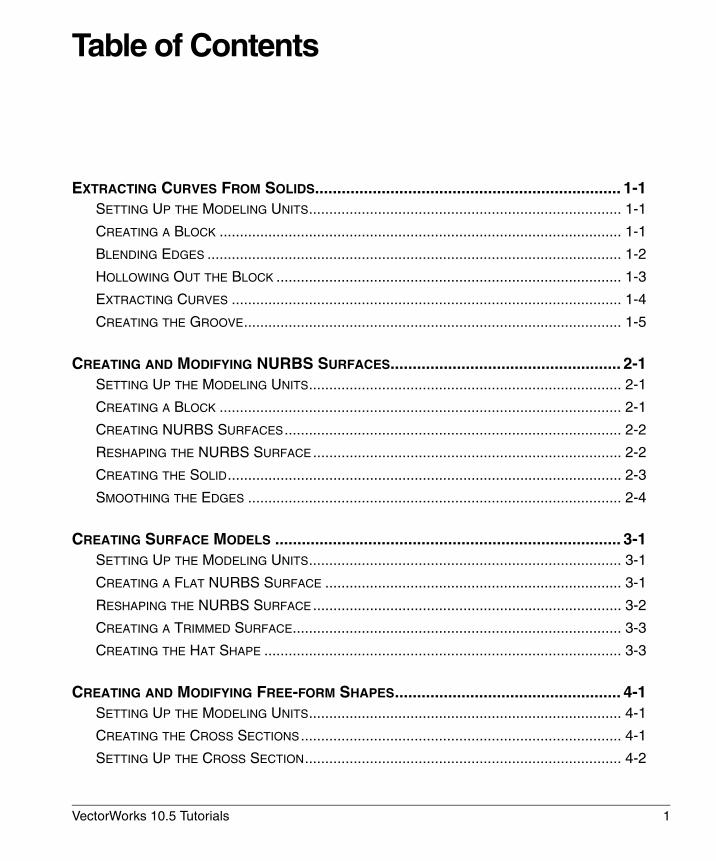
Table of Contents
EXTRACTING CURVES FROM SOLIDS..................................................................... 1-1SETTING UP THE MODELING UNITS............................................................................. 1-1
CREATING A BLOCK ................................................................................................... 1-1
BLENDING EDGES ...................................................................................................... 1-2
HOLLOWING OUT THE BLOCK ..................................................................................... 1-3
EXTRACTING CURVES ................................................................................................ 1-4
CREATING THE GROOVE............................................................................................. 1-5
CREATING AND MODIFYING NURBS SURFACES.................................................... 2-1SETTING UP THE MODELING UNITS............................................................................. 2-1
CREATING A BLOCK ................................................................................................... 2-1
CREATING NURBS SURFACES................................................................................... 2-2
RESHAPING THE NURBS SURFACE............................................................................ 2-2
CREATING THE SOLID................................................................................................. 2-3
SMOOTHING THE EDGES ............................................................................................ 2-4
CREATING SURFACE MODELS .............................................................................. 3-1SETTING UP THE MODELING UNITS............................................................................. 3-1
CREATING A FLAT NURBS SURFACE ......................................................................... 3-1
RESHAPING THE NURBS SURFACE............................................................................ 3-2
CREATING A TRIMMED SURFACE................................................................................. 3-3
CREATING THE HAT SHAPE ........................................................................................ 3-3
CREATING AND MODIFYING FREE-FORM SHAPES................................................... 4-1SETTING UP THE MODELING UNITS............................................................................. 4-1
CREATING THE CROSS SECTIONS............................................................................... 4-1
SETTING UP THE CROSS SECTION.............................................................................. 4-2
VectorWorks 10.5 Tutorials 1
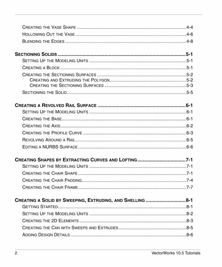
CREATING THE VASE SHAPE .......................................................................................4-4
HOLLOWING OUT THE VASE ........................................................................................4-6
BLENDING THE EDGES ................................................................................................4-8
SECTIONING SOLIDS .............................................................................................5-1SETTING UP THE MODELING UNITS .............................................................................5-1
CREATING A BLOCK ....................................................................................................5-1
CREATING THE SECTIONING SURFACES .......................................................................5-2CREATING AND EXTRUDING THE POLYGON.............................................................5-2CREATING THE SECTIONING SURFACES .................................................................5-3
SECTIONING THE SOLID...............................................................................................5-5
CREATING A REVOLVED RAIL SURFACE ................................................................6-1SETTING UP THE MODELING UNITS .............................................................................6-1
CREATING THE BASE...................................................................................................6-1
CREATING THE AXIS....................................................................................................6-2
CREATING THE PROFILE CURVE ..................................................................................6-3
REVOLVING AROUND A RAIL........................................................................................6-5
EDITING A NURBS SURFACE ......................................................................................6-6
CREATING SHAPES BY EXTRACTING CURVES AND LOFTING...................................7-1SETTING UP THE MODELING UNITS .............................................................................7-1
CREATING THE CHAIR SHAPE ......................................................................................7-1
CREATING THE CHAIR PADDING...................................................................................7-4
CREATING THE CHAIR FRAME......................................................................................7-7
CREATING A SOLID BY SWEEPING, EXTRUDING, AND SHELLING .............................8-1GETTING STARTED......................................................................................................8-1
SETTING UP THE MODELING UNITS .............................................................................8-2
CREATING THE 2D ELEMENTS .....................................................................................8-3
CREATING THE CAN WITH SWEEPS AND EXTRUDES......................................................8-5
ADDING DESIGN DETAILS ............................................................................................8-6
2 VectorWorks 10.5 Tutorials
TOC
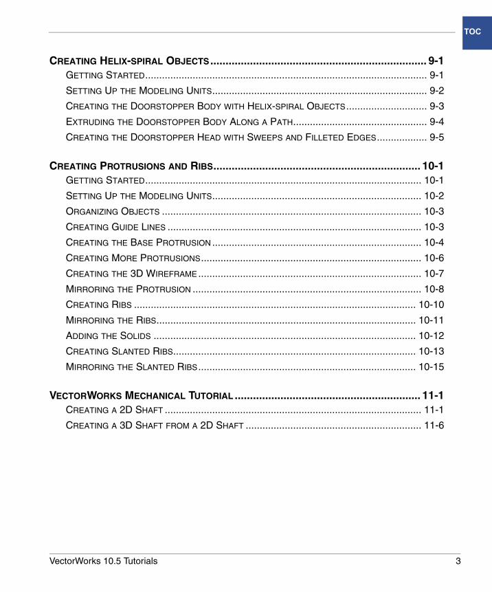
CREATING HELIX-SPIRAL OBJECTS....................................................................... 9-1GETTING STARTED..................................................................................................... 9-1
SETTING UP THE MODELING UNITS............................................................................. 9-2
CREATING THE DOORSTOPPER BODY WITH HELIX-SPIRAL OBJECTS............................. 9-3
EXTRUDING THE DOORSTOPPER BODY ALONG A PATH................................................ 9-4
CREATING THE DOORSTOPPER HEAD WITH SWEEPS AND FILLETED EDGES.................. 9-5
CREATING PROTRUSIONS AND RIBS.................................................................... 10-1GETTING STARTED................................................................................................... 10-1
SETTING UP THE MODELING UNITS........................................................................... 10-2
ORGANIZING OBJECTS ............................................................................................. 10-3
CREATING GUIDE LINES ........................................................................................... 10-3
CREATING THE BASE PROTRUSION ........................................................................... 10-4
CREATING MORE PROTRUSIONS............................................................................... 10-6
CREATING THE 3D WIREFRAME................................................................................ 10-7
MIRRORING THE PROTRUSION .................................................................................. 10-8
CREATING RIBS ..................................................................................................... 10-10
MIRRORING THE RIBS............................................................................................. 10-11
ADDING THE SOLIDS .............................................................................................. 10-12
CREATING SLANTED RIBS....................................................................................... 10-13
MIRRORING THE SLANTED RIBS.............................................................................. 10-15
VECTORWORKS MECHANICAL TUTORIAL ............................................................. 11-1CREATING A 2D SHAFT ............................................................................................ 11-1
CREATING A 3D SHAFT FROM A 2D SHAFT ............................................................... 11-6
VectorWorks 10.5 Tutorials 3
1
Extracting Curves From Solids• Setting Up the Modeling Units
• Creating a Block
• Blending Edges
• Hollowing Out the Block
• Extracting Curves
• Creating the Groove
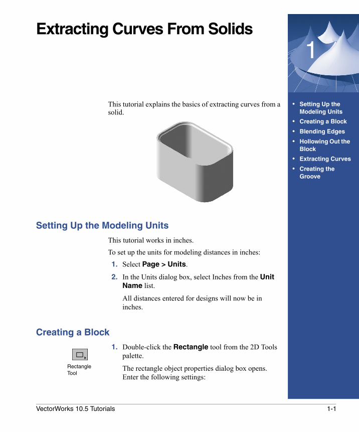
This tutorial explains the basics of extracting curves from a solid.
Setting Up the Modeling Units
This tutorial works in inches.To set up the units for modeling distances in inches: 1. Select Page > Units.
2. In the Units dialog box, select Inches from the Unit Name list.
All distances entered for designs will now be in inches.
Creating a Block
1. Double-click the Rectangle tool from the 2D Tools palette.
The rectangle object properties dialog box opens. Enter the following settings:
Rectangle Tool
1-1VectorWorks 10.5 Tutorials
Extracting Curves From Solids
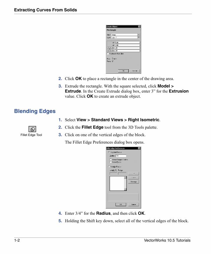
2. Click OK to place a rectangle in the center of the drawing area.
3. Extrude the rectangle. With the square selected, click Model > Extrude. In the Create Extrude dialog box, enter 3” for the Extrusion value. Click OK to create an extrude object.
Blending Edges
1. Select View > Standard Views > Right Isometric.
2. Click the Fillet Edge tool from the 3D Tools palette.
3. Click on one of the vertical edges of the block.
The Fillet Edge Preferences dialog box opens.
4. Enter 3/4” for the Radius, and then click OK.
5. Holding the Shift key down, select all of the vertical edges of the block.
Fillet Edge Tool
1-2 VectorWorks 10.5 Tutorials
Hollowing Out the Block1
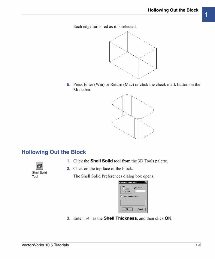
Each edge turns red as it is selected.
6. Press Enter (Win) or Return (Mac) or click the check mark button on the Mode bar.
Hollowing Out the Block
1. Click the Shell Solid tool from the 3D Tools palette.
2. Click on the top face of the block.
The Shell Solid Preferences dialog box opens.
3. Enter 1/4” as the Shell Thickness, and then click OK.
Shell Solid Tool
1-3VectorWorks 10.5 Tutorials

Extracting Curves From Solids
The top face of the block is highlighted in red (alternatively, select it from the Select Faces dialog box).
4. Press Enter (Win) or Return (Mac) or click the check mark button on the Mode bar to create the shell.
Extracting Curves
1. Click the Extract tool from the 3D Tools palette, and select Extract Curve from the Mode bar.
2. Holding the Shift key down, select all of the top inner edges of the block.Extract Tool
1-4 VectorWorks 10.5 Tutorials
Creating the Groove1
3. Press Enter (Win) or Return (Mac) or click the check mark button on the Mode bar.
4. Select Organize > Ungroup.
5. Select Tool > Compose.
Creating the Groove
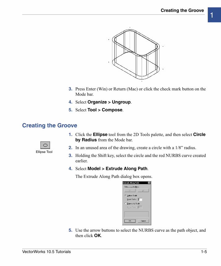
1. Click the Ellipse tool from the 2D Tools palette, and then select Circle by Radius from the Mode bar.
2. In an unused area of the drawing, create a circle with a 1/8” radius.
3. Holding the Shift key, select the circle and the red NURBS curve created earlier.
4. Select Model > Extrude Along Path.
The Extrude Along Path dialog box opens.
5. Use the arrow buttons to select the NURBS curve as the path object, and then click OK.
Ellipse Tool
1-5VectorWorks 10.5 Tutorials
Extracting Curves From Solids
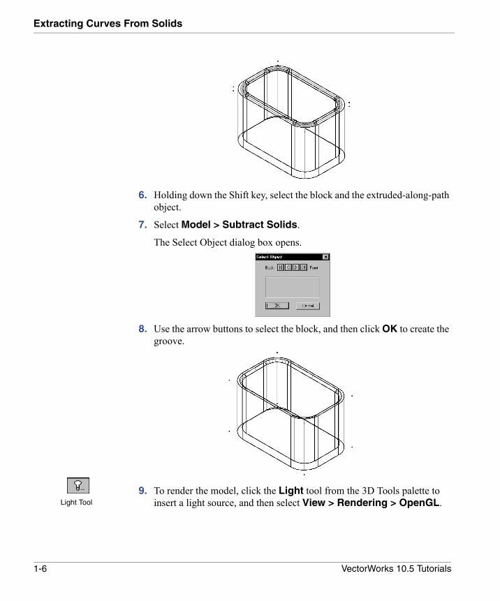
6. Holding down the Shift key, select the block and the extruded-along-path object.
7. Select Model > Subtract Solids.
The Select Object dialog box opens.
8. Use the arrow buttons to select the block, and then click OK to create the groove.
9. To render the model, click the Light tool from the 3D Tools palette to insert a light source, and then select View > Rendering > OpenGL.Light Tool
1-6 VectorWorks 10.5 Tutorials
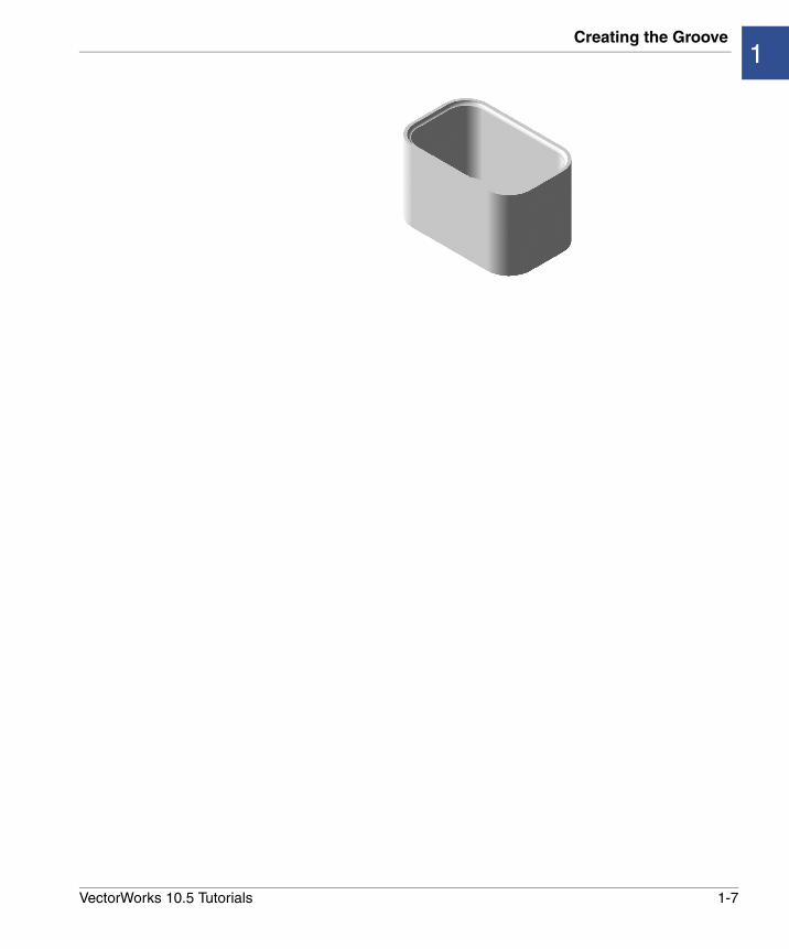
Creating the Groove1
1-7VectorWorks 10.5 Tutorials
2
Creating and Modifying NURBS SurfacesIn this Chapter:
• Setting Up the Modeling Units
• Creating a Block
• Creating NURBS Surfaces
• Reshaping the NURBS Surface
• Creating the Solid
• Smoothing the Edges
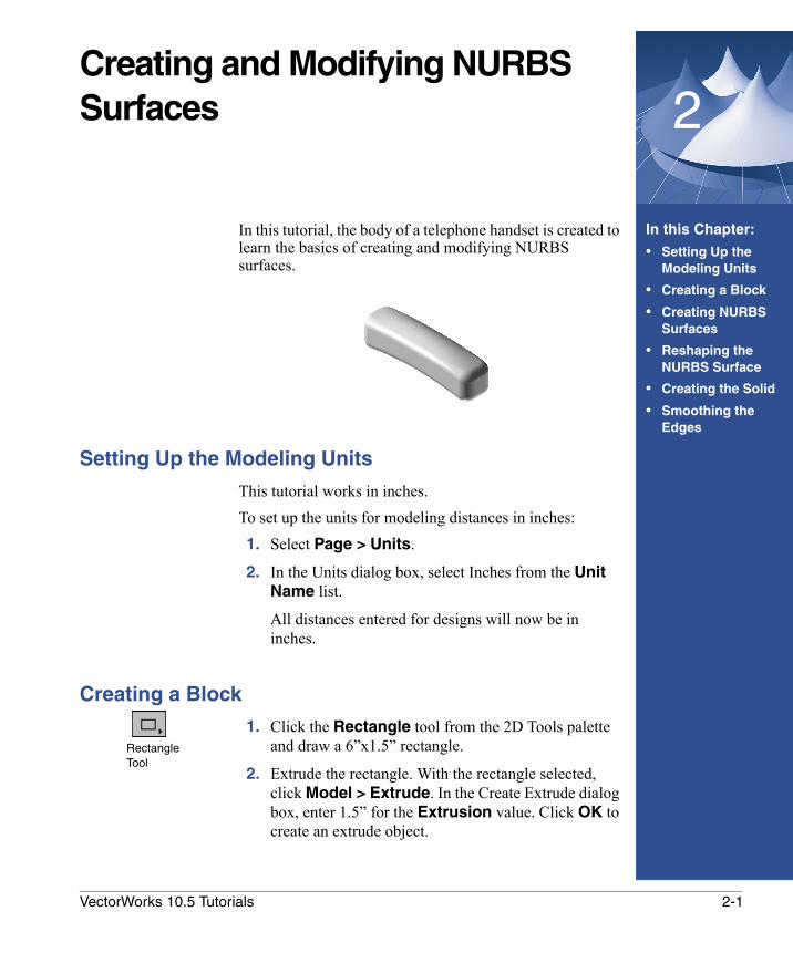
In this tutorial, the body of a telephone handset is created to learn the basics of creating and modifying NURBS surfaces.
Setting Up the Modeling Units
This tutorial works in inches.To set up the units for modeling distances in inches: 1. Select Page > Units.
2. In the Units dialog box, select Inches from the Unit Name list.
All distances entered for designs will now be in inches.
Creating a Block
1. Click the Rectangle tool from the 2D Tools palette and draw a 6”x1.5” rectangle.
2. Extrude the rectangle. With the rectangle selected, click Model > Extrude. In the Create Extrude dialog box, enter 1.5” for the Extrusion value. Click OK to create an extrude object.
Rectangle Tool
2-1VectorWorks 10.5 Tutorials
Creating and Modifying NURBS Surfaces
Creating NURBS Surfaces
1. Convert the extrude object to NURBS surfaces using the Model > Convert to NURBS command, which creates a group of NURBS surfaces.
2. Select Organize > Ungroup to get six individual surfaces for the six faces of the extrusion. Deselect all the surfaces.
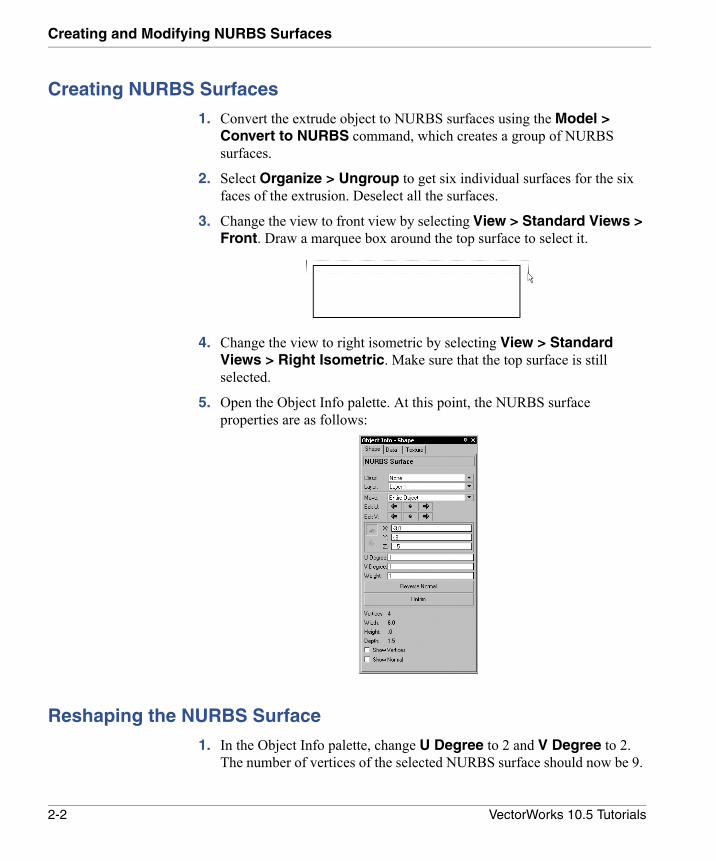
3. Change the view to front view by selecting View > Standard Views > Front. Draw a marquee box around the top surface to select it.
4. Change the view to right isometric by selecting View > Standard Views > Right Isometric. Make sure that the top surface is still selected.
5. Open the Object Info palette. At this point, the NURBS surface properties are as follows:
Reshaping the NURBS Surface
1. In the Object Info palette, change U Degree to 2 and V Degree to 2. The number of vertices of the selected NURBS surface should now be 9.
2-2 VectorWorks 10.5 Tutorials
Creating the Solid2
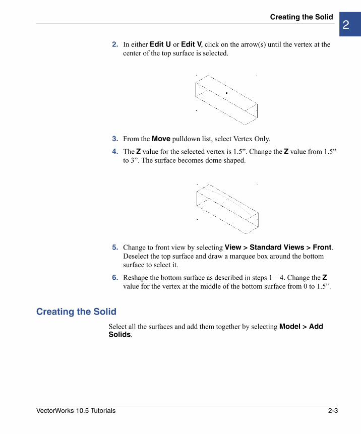
2. In either Edit U or Edit V, click on the arrow(s) until the vertex at the center of the top surface is selected.
3. From the Move pulldown list, select Vertex Only.
4. The Z value for the selected vertex is 1.5”. Change the Z value from 1.5” to 3”. The surface becomes dome shaped.
5. Change to front view by selecting View > Standard Views > Front. Deselect the top surface and draw a marquee box around the bottom surface to select it.
6. Reshape the bottom surface as described in steps 1 – 4. Change the Z value for the vertex at the middle of the bottom surface from 0 to 1.5”.
Creating the Solid
Select all the surfaces and add them together by selecting Model > Add Solids.
2-3VectorWorks 10.5 Tutorials
Creating and Modifying NURBS Surfaces
Smoothing the Edges
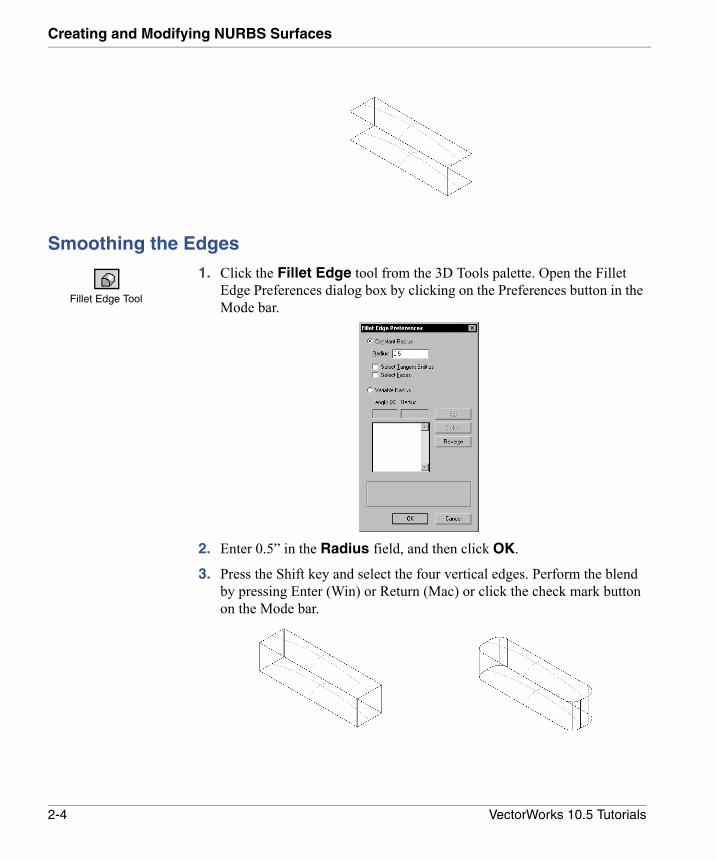
1. Click the Fillet Edge tool from the 3D Tools palette. Open the Fillet Edge Preferences dialog box by clicking on the Preferences button in the Mode bar.
2. Enter 0.5” in the Radius field, and then click OK.
3. Press the Shift key and select the four vertical edges. Perform the blend by pressing Enter (Win) or Return (Mac) or click the check mark button on the Mode bar.
Fillet Edge Tool
2-4 VectorWorks 10.5 Tutorials
Smoothing the Edges2
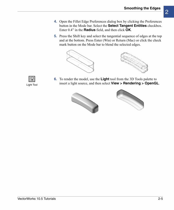
4. Open the Fillet Edge Preferences dialog box by clicking the Preferences button in the Mode bar. Select the Select Tangent Entities checkbox. Enter 0.4” in the Radius field, and then click OK.
5. Press the Shift key and select the tangential sequence of edges at the top and at the bottom. Press Enter (Win) or Return (Mac) or click the check mark button on the Mode bar to blend the selected edges.
6. To render the model, use the Light tool from the 3D Tools palette to insert a light source, and then select View > Rendering > OpenGL.Light Tool
2-5VectorWorks 10.5 Tutorials
3
Creating Surface ModelsIn this Chapter:
• Setting Up the Modeling Units
• Creating a Flat NURBS Surface
• Reshaping the NURBS Surface
• Creating a Trimmed Surface
• Creating the Hat Shape
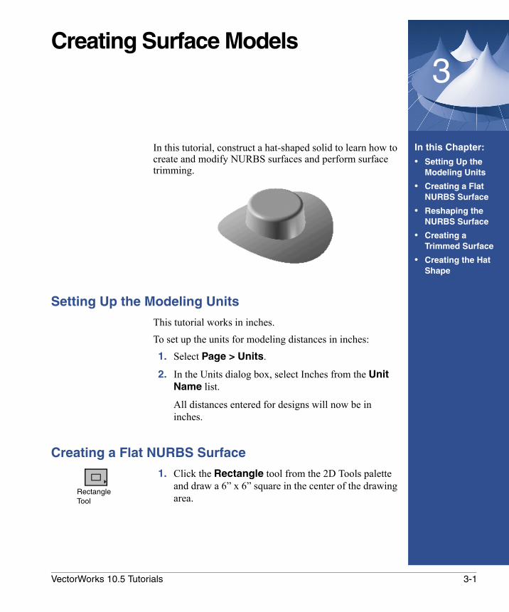
In this tutorial, construct a hat-shaped solid to learn how to create and modify NURBS surfaces and perform surface trimming.
Setting Up the Modeling Units
This tutorial works in inches.To set up the units for modeling distances in inches: 1. Select Page > Units.
2. In the Units dialog box, select Inches from the Unit Name list.
All distances entered for designs will now be in inches.
Creating a Flat NURBS Surface
1. Click the Rectangle tool from the 2D Tools palette and draw a 6” x 6” square in the center of the drawing area.
RectangleTool
3-1VectorWorks 10.5 Tutorials
Creating Surface Models
2. Extrude the square by selecting it and then clicking Model > Extrude. In the Create Extrude dialog box, enter 0 (zero) for the Extrusion value. Click OK to create an extrude object with zero height.
3. Select Model > Convert to NURBS.
The extrude object is converted to NURBS surfaces.
Reshaping the NURBS Surface
1. In the Object Info palette, change both the U Degree and V Degree values to 2.
The number of Vertices for the selected NURBS surface is now 9.
2. From the Move list, select Vertex Only.
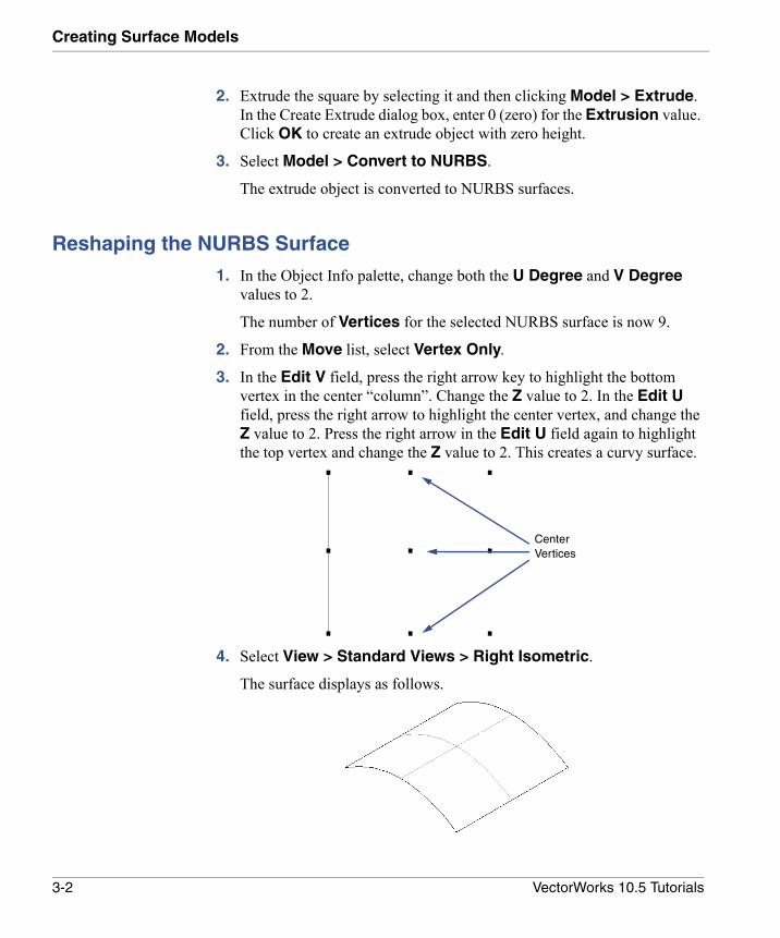
3. In the Edit V field, press the right arrow key to highlight the bottom vertex in the center “column”. Change the Z value to 2. In the Edit U field, press the right arrow to highlight the center vertex, and change the Z value to 2. Press the right arrow in the Edit U field again to highlight the top vertex and change the Z value to 2. This creates a curvy surface.
4. Select View > Standard Views > Right Isometric.
The surface displays as follows.
Center Vertices
3-2 VectorWorks 10.5 Tutorials
Creating a Trimmed Surface3
Creating a Trimmed Surface
1. Select View > Standard Views > Top to change to drawing view.
2. Click the Ellipse tool from the 2D Tools palette, and then select Circle by Radius from the Mode bar.
3. Draw a circle at the center of the NURBS surface with a 2.75” radius.
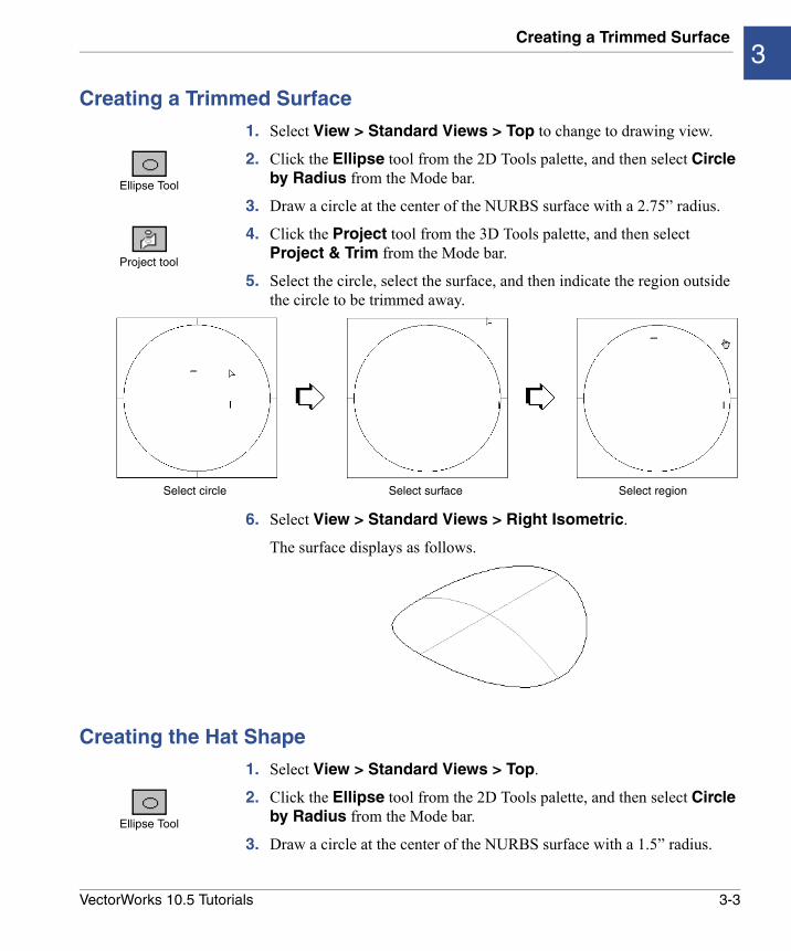
4. Click the Project tool from the 3D Tools palette, and then select Project & Trim from the Mode bar.
5. Select the circle, select the surface, and then indicate the region outside the circle to be trimmed away.
6. Select View > Standard Views > Right Isometric.
The surface displays as follows.
Creating the Hat Shape
1. Select View > Standard Views > Top.
2. Click the Ellipse tool from the 2D Tools palette, and then select Circle by Radius from the Mode bar.
3. Draw a circle at the center of the NURBS surface with a 1.5” radius.
Ellipse Tool
Project tool
Select circle Select surface Select region
Ellipse Tool
3-3VectorWorks 10.5 Tutorials
Creating Surface Models
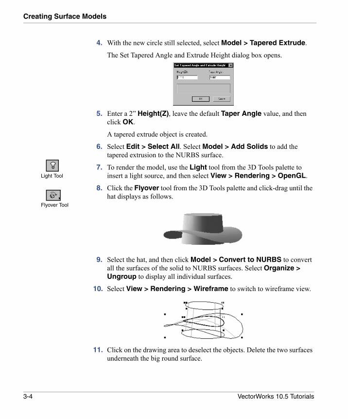
4. With the new circle still selected, select Model > Tapered Extrude.
The Set Tapered Angle and Extrude Height dialog box opens.
5. Enter a 2” Height(Z), leave the default Taper Angle value, and then click OK.
A tapered extrude object is created.
6. Select Edit > Select All. Select Model > Add Solids to add the tapered extrusion to the NURBS surface.
7. To render the model, use the Light tool from the 3D Tools palette to insert a light source, and then select View > Rendering > OpenGL.
8. Click the Flyover tool from the 3D Tools palette and click-drag until the hat displays as follows.
9. Select the hat, and then click Model > Convert to NURBS to convert all the surfaces of the solid to NURBS surfaces. Select Organize > Ungroup to display all individual surfaces.
10. Select View > Rendering > Wireframe to switch to wireframe view.
11. Click on the drawing area to deselect the objects. Delete the two surfaces underneath the big round surface.
Light Tool
Flyover Tool
3-4 VectorWorks 10.5 Tutorials
Creating the Hat Shape3
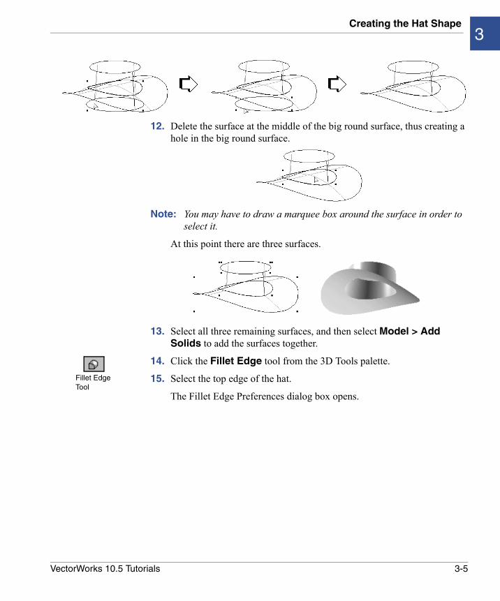
12. Delete the surface at the middle of the big round surface, thus creating a hole in the big round surface.
Note: You may have to draw a marquee box around the surface in order to select it.
At this point there are three surfaces.
13. Select all three remaining surfaces, and then select Model > Add Solids to add the surfaces together.
14. Click the Fillet Edge tool from the 3D Tools palette.
15. Select the top edge of the hat.
The Fillet Edge Preferences dialog box opens.
Fillet Edge Tool
3-5VectorWorks 10.5 Tutorials
Creating Surface Models
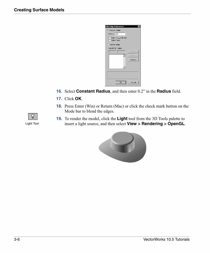
16. Select Constant Radius, and then enter 0.2” in the Radius field.
17. Click OK.
18. Press Enter (Win) or Return (Mac) or click the check mark button on the Mode bar to blend the edges.
19. To render the model, click the Light tool from the 3D Tools palette to insert a light source, and then select View > Rendering > OpenGL.Light Tool
3-6 VectorWorks 10.5 Tutorials
4
Creating and Modifying Free-form ShapesIn this Chapter:
• Setting Up the Modeling Units
• Creating the Cross Sections
• Setting Up the Cross Section
• Creating the Vase Shape
• Hollowing Out the Vase
• Blending the Edges
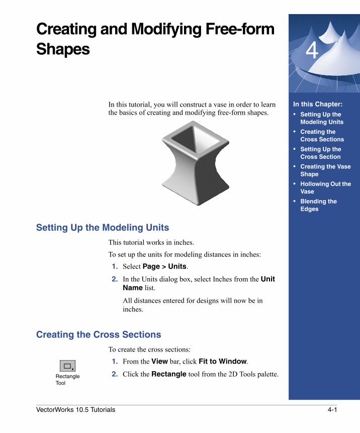
In this tutorial, you will construct a vase in order to learn the basics of creating and modifying free-form shapes.
Setting Up the Modeling Units
This tutorial works in inches.To set up the units for modeling distances in inches: 1. Select Page > Units.
2. In the Units dialog box, select Inches from the Unit Name list.
All distances entered for designs will now be in inches.
Creating the Cross Sections
To create the cross sections:1. From the View bar, click Fit to Window.
2. Click the Rectangle tool from the 2D Tools palette.Rectangle Tool
4-1VectorWorks 10.5 Tutorials
Creating and Modifying Free-form Shapes
3. Click on the lower left side of the drawing area, and then press Tab to highlight the +/-X field. Enter 6”, and then press Enter (Win) or Return (Mac).
4. Press Tab until the +/-Y field is highlighted. Enter 5”, and then press Enter (Win) or Return (Mac). Click on the drawing area to set the rectangle.
5. With the rectangle still highlighted, select Edit > Copy.
6. Select Edit > Paste.
A copy of the rectangle is placed on the drawing.
7. Select the Rectangle tool.
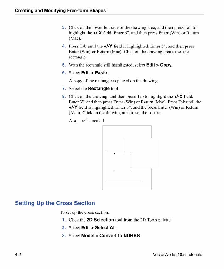
8. Click on the drawing, and then press Tab to highlight the +/-X field. Enter 3”, and then press Enter (Win) or Return (Mac). Press Tab until the +/-Y field is highlighted. Enter 3”, and the press Enter (Win) or Return (Mac). Click on the drawing area to set the square.
A square is created.
Setting Up the Cross Section
To set up the cross section:1. Click the 2D Selection tool from the 2D Tools palette.
2. Select Edit > Select All.
3. Select Model > Convert to NURBS.
4-2 VectorWorks 10.5 Tutorials
Setting Up the Cross Section4
4. Select Organize > Ungroup.
5. Deselect the rectangles by clicking on a unused area of the drawing.
6. Select one of the two larger rectangles.
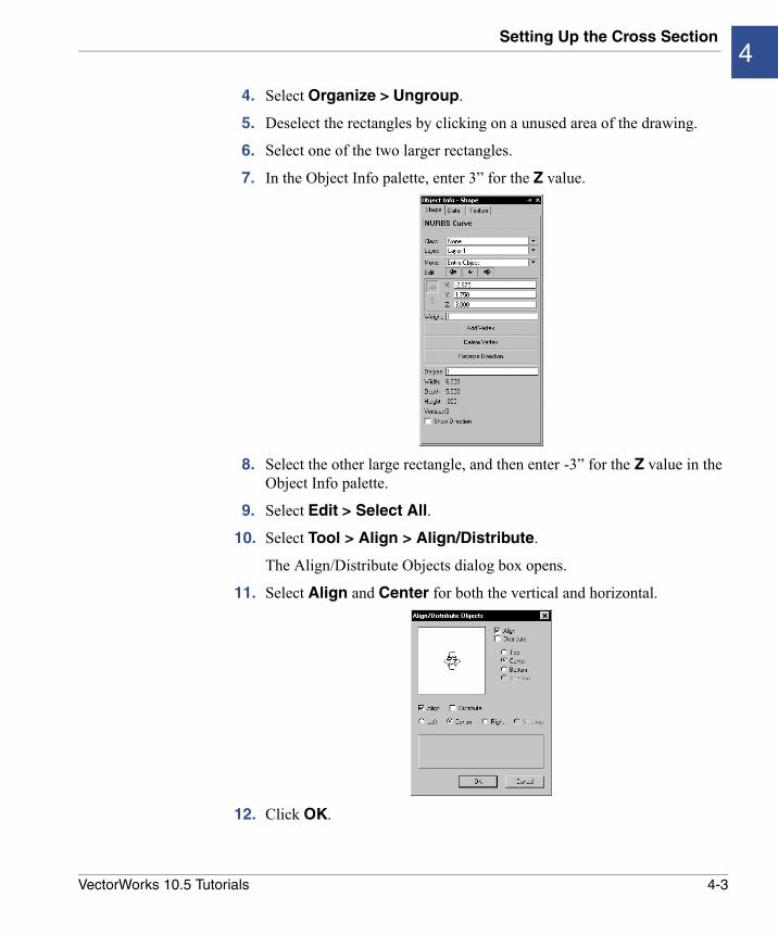
7. In the Object Info palette, enter 3” for the Z value.
8. Select the other large rectangle, and then enter -3” for the Z value in the Object Info palette.
9. Select Edit > Select All.
10. Select Tool > Align > Align/Distribute.
The Align/Distribute Objects dialog box opens.
11. Select Align and Center for both the vertical and horizontal.
12. Click OK.
4-3VectorWorks 10.5 Tutorials
Creating and Modifying Free-form Shapes
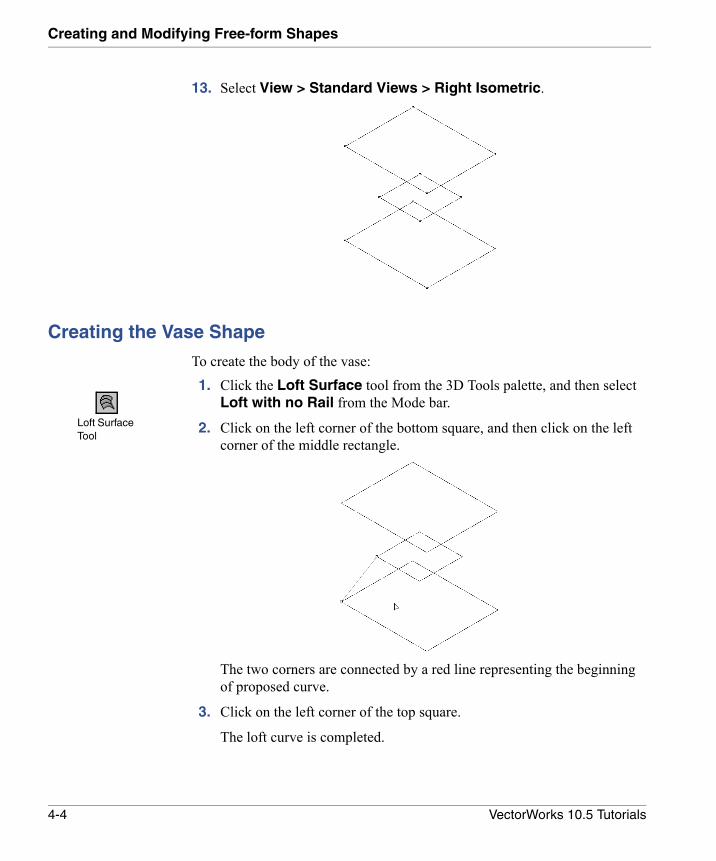
13. Select View > Standard Views > Right Isometric.
Creating the Vase Shape
To create the body of the vase:1. Click the Loft Surface tool from the 3D Tools palette, and then select
Loft with no Rail from the Mode bar.
2. Click on the left corner of the bottom square, and then click on the left corner of the middle rectangle.
The two corners are connected by a red line representing the beginning of proposed curve.
3. Click on the left corner of the top square.
The loft curve is completed.
Loft Surface Tool
4-4 VectorWorks 10.5 Tutorials
Creating the Vase Shape4
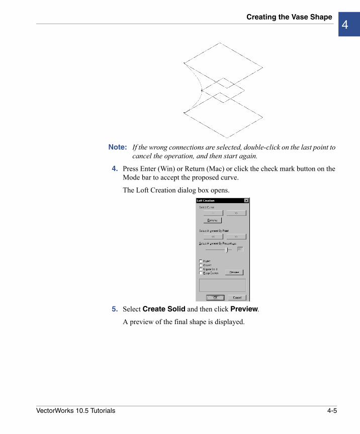
Note: If the wrong connections are selected, double-click on the last point to cancel the operation, and then start again.
4. Press Enter (Win) or Return (Mac) or click the check mark button on the Mode bar to accept the proposed curve.
The Loft Creation dialog box opens.
5. Select Create Solid and then click Preview.
A preview of the final shape is displayed.
4-5VectorWorks 10.5 Tutorials
Creating and Modifying Free-form Shapes
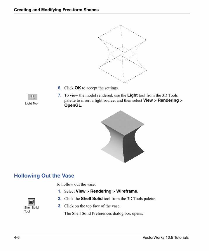
6. Click OK to accept the settings.
7. To view the model rendered, use the Light tool from the 3D Tools palette to insert a light source, and then select View > Rendering > OpenGL.
Hollowing Out the Vase
To hollow out the vase:1. Select View > Rendering > Wireframe.
2. Click the Shell Solid tool from the 3D Tools palette.
3. Click on the top face of the vase.
The Shell Solid Preferences dialog box opens.
Light Tool
Shell Solid Tool
4-6 VectorWorks 10.5 Tutorials
Hollowing Out the Vase4
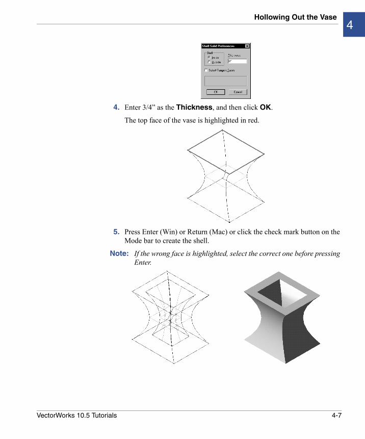
4. Enter 3/4” as the Thickness, and then click OK.
The top face of the vase is highlighted in red.
5. Press Enter (Win) or Return (Mac) or click the check mark button on the Mode bar to create the shell.
Note: If the wrong face is highlighted, select the correct one before pressing Enter.
4-7VectorWorks 10.5 Tutorials
Creating and Modifying Free-form Shapes
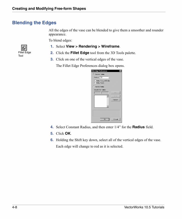
Blending the Edges
All the edges of the vase can be blended to give them a smoother and rounder appearance.To blend edges:1. Select View > Rendering > Wireframe.
2. Click the Fillet Edge tool from the 3D Tools palette.
3. Click on one of the vertical edges of the vase.
The Fillet Edge Preferences dialog box opens.
4. Select Constant Radius, and then enter 1/4” for the Radius field.
5. Click OK.
6. Holding the Shift key down, select all of the vertical edges of the vase.
Each edge will change to red as it is selected.
Fillet Edge Tool
4-8 VectorWorks 10.5 Tutorials
Blending the Edges4
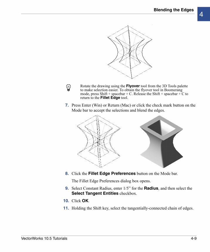
7. Press Enter (Win) or Return (Mac) or click the check mark button on the Mode bar to accept the selections and blend the edges.
8. Click the Fillet Edge Preferences button on the Mode bar.
The Fillet Edge Preferences dialog box opens.
9. Select Constant Radius, enter 1/5” for the Radius, and then select the Select Tangent Entities checkbox.
10. Click OK.
11. Holding the Shift key, select the tangentially-connected chain of edges.
Rotate the drawing using the Flyover tool from the 3D Tools palette to make selection easier. To obtain the flyover tool in Boomerang mode, press Shift + spacebar + C. Release the Shift + spacebar + C to return to the Fillet Edge tool.
4-9VectorWorks 10.5 Tutorials
Creating and Modifying Free-form Shapes
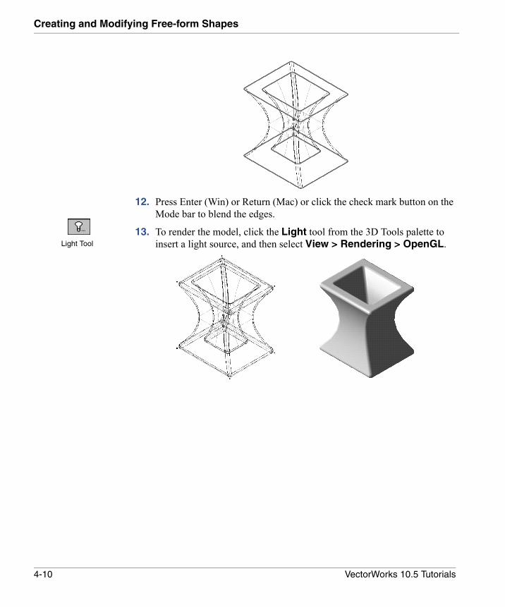
12. Press Enter (Win) or Return (Mac) or click the check mark button on the Mode bar to blend the edges.
13. To render the model, click the Light tool from the 3D Tools palette to insert a light source, and then select View > Rendering > OpenGL.Light Tool
4-10 VectorWorks 10.5 Tutorials
5
Sectioning SolidsIn this Chapter:
• Setting Up the Modeling Units
• Creating a Block
• Creating the Sectioning Surfaces
• Sectioning the Solid
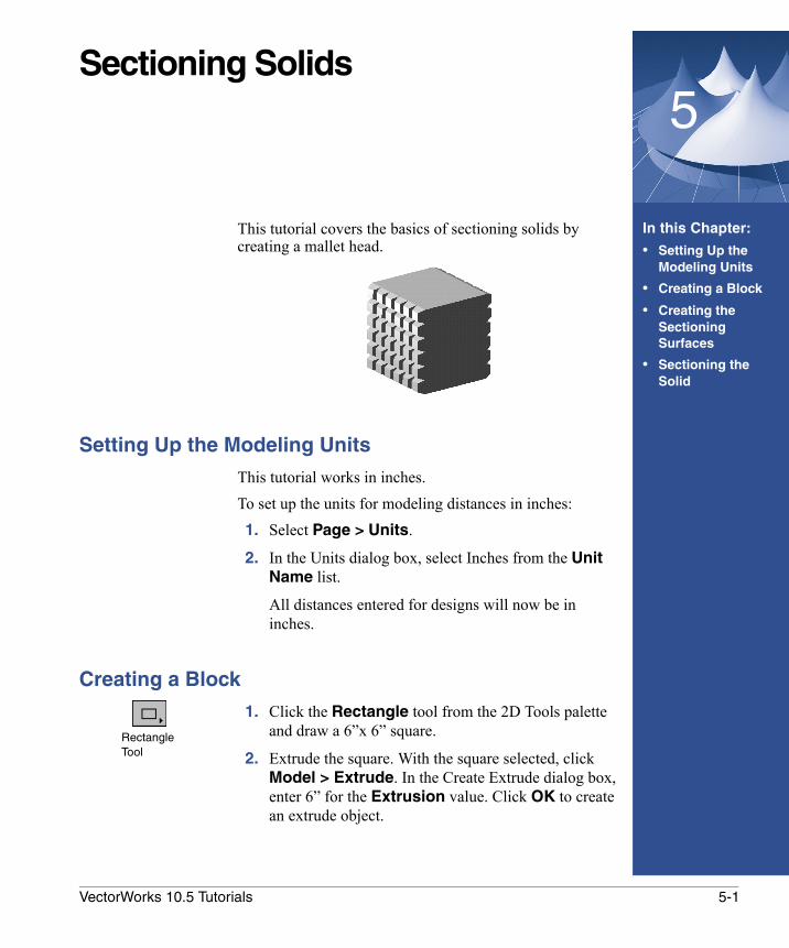
This tutorial covers the basics of sectioning solids by creating a mallet head.
Setting Up the Modeling Units
This tutorial works in inches.To set up the units for modeling distances in inches: 1. Select Page > Units.
2. In the Units dialog box, select Inches from the Unit Name list.
All distances entered for designs will now be in inches.
Creating a Block
1. Click the Rectangle tool from the 2D Tools palette and draw a 6”x 6” square.
2. Extrude the square. With the square selected, click Model > Extrude. In the Create Extrude dialog box, enter 6” for the Extrusion value. Click OK to create an extrude object.
Rectangle Tool
5-1VectorWorks 10.5 Tutorials
Sectioning Solids
Creating the Sectioning Surfaces
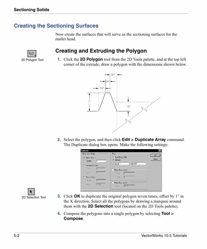
Now create the surfaces that will serve as the sectioning surfaces for the mallet head.
Creating and Extruding the Polygon
1. Click the 2D Polygon tool from the 2D Tools palette, and at the top left corner of the extrude, draw a polygon with the dimensions shown below.
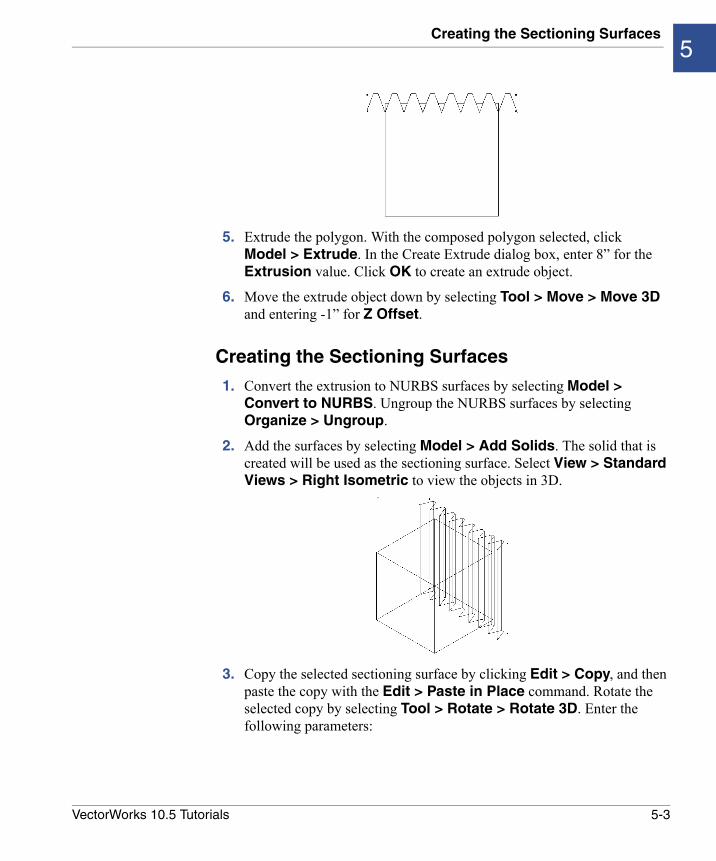
2. Select the polygon, and then click Edit > Duplicate Array command. The Duplicate dialog box opens. Make the following settings:
3. Click OK to duplicate the original polygon seven times, offset by 1” in the X direction. Select all the polygons by drawing a marquee around them with the 2D Selection tool (located on the 2D Tools palette).
4. Compose the polygons into a single polygon by selecting Tool > Compose.
2D Polygon Tool
2D Selection Tool
5-2 VectorWorks 10.5 Tutorials
Creating the Sectioning Surfaces5
5. Extrude the polygon. With the composed polygon selected, clickModel > Extrude. In the Create Extrude dialog box, enter 8” for the Extrusion value. Click OK to create an extrude object.
6. Move the extrude object down by selecting Tool > Move > Move 3D and entering -1” for Z Offset.
Creating the Sectioning Surfaces
1. Convert the extrusion to NURBS surfaces by selecting Model > Convert to NURBS. Ungroup the NURBS surfaces by selecting Organize > Ungroup.
2. Add the surfaces by selecting Model > Add Solids. The solid that is created will be used as the sectioning surface. Select View > Standard Views > Right Isometric to view the objects in 3D.
3. Copy the selected sectioning surface by clicking Edit > Copy, and then paste the copy with the Edit > Paste in Place command. Rotate the selected copy by selecting Tool > Rotate > Rotate 3D. Enter the following parameters:
5-3VectorWorks 10.5 Tutorials
Sectioning Solids
The copy of the sectioning surface is rotated 90o from the original. There are now two sectioning surfaces.
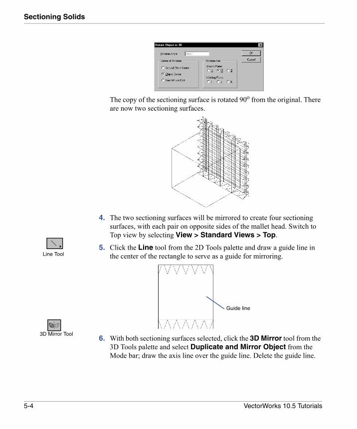
4. The two sectioning surfaces will be mirrored to create four sectioning surfaces, with each pair on opposite sides of the mallet head. Switch to Top view by selecting View > Standard Views > Top.
5. Click the Line tool from the 2D Tools palette and draw a guide line in the center of the rectangle to serve as a guide for mirroring.
6. With both sectioning surfaces selected, click the 3D Mirror tool from the 3D Tools palette and select Duplicate and Mirror Object from the Mode bar; draw the axis line over the guide line. Delete the guide line.
Line Tool
Guide line
3D Mirror Tool
5-4 VectorWorks 10.5 Tutorials
Sectioning the Solid5
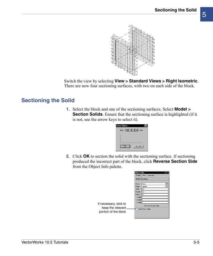
Switch the view by selecting View > Standard Views > Right Isometric. There are now four sectioning surfaces, with two on each side of the block.
Sectioning the Solid
1. Select the block and one of the sectioning surfaces. Select Model > Section Solids. Ensure that the sectioning surface is highlighted (if it is not, use the arrow keys to select it).
2. Click OK to section the solid with the sectioning surface. If sectioning produced the incorrect part of the block, click Reverse Section Side from the Object Info palette.
If necessary, click tokeep the relevant
portion of the block
5-5VectorWorks 10.5 Tutorials
Sectioning Solids
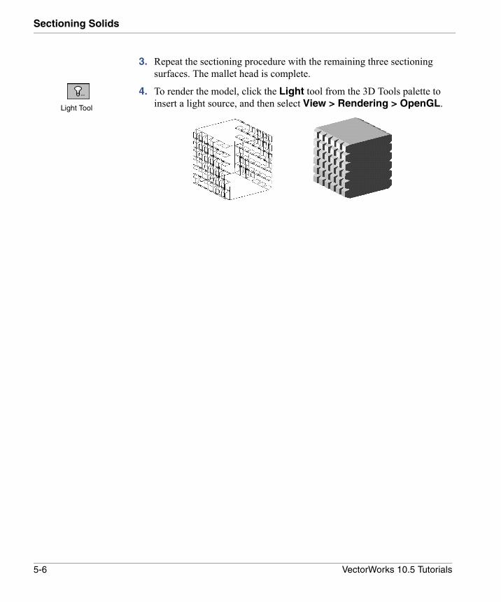
3. Repeat the sectioning procedure with the remaining three sectioning surfaces. The mallet head is complete.
4. To render the model, click the Light tool from the 3D Tools palette to insert a light source, and then select View > Rendering > OpenGL.Light Tool
5-6 VectorWorks 10.5 Tutorials
6
Creating a Revolved Rail Surface• Setting Up the Modeling Units
• Creating the Base
• Creating the Axis
• Creating the Profile Curve
• Revolving Around a Rail
• Editing a NURBS Surface
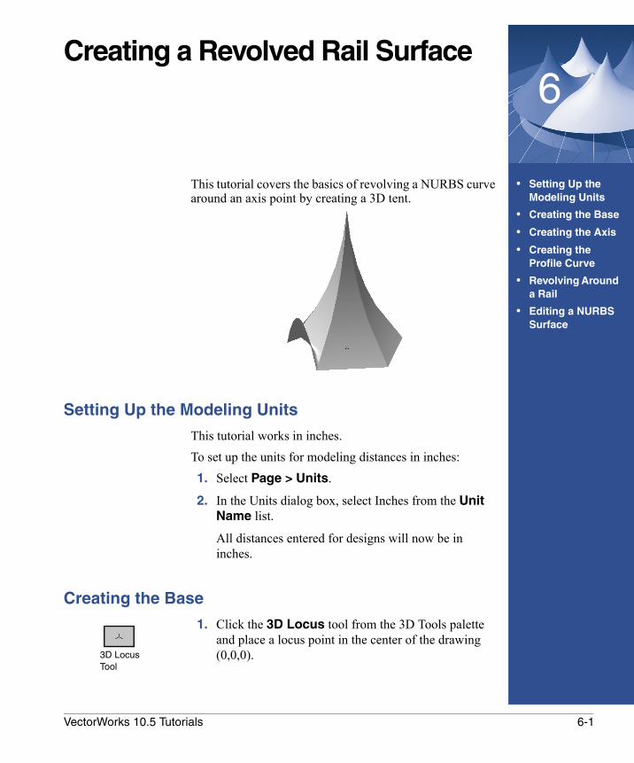
This tutorial covers the basics of revolving a NURBS curve around an axis point by creating a 3D tent.
Setting Up the Modeling Units
This tutorial works in inches.To set up the units for modeling distances in inches: 1. Select Page > Units.
2. In the Units dialog box, select Inches from the Unit Name list.
All distances entered for designs will now be in inches.
Creating the Base
1. Click the 3D Locus tool from the 3D Tools palette and place a locus point in the center of the drawing (0,0,0).3D Locus
Tool
6-1VectorWorks 10.5 Tutorials
Creating a Revolved Rail Surface
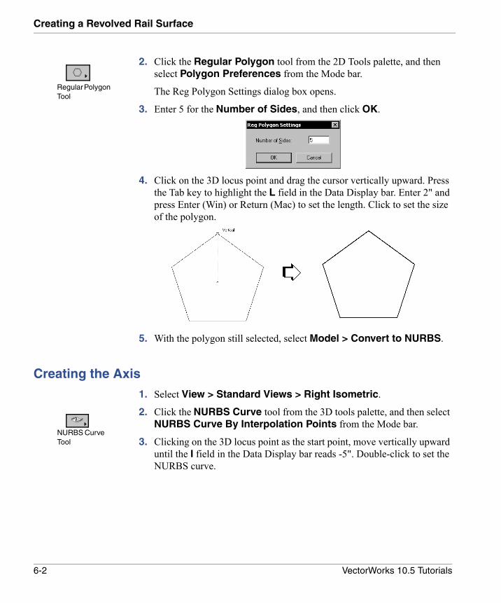
2. Click the Regular Polygon tool from the 2D Tools palette, and then select Polygon Preferences from the Mode bar.
The Reg Polygon Settings dialog box opens.
3. Enter 5 for the Number of Sides, and then click OK.
4. Click on the 3D locus point and drag the cursor vertically upward. Press the Tab key to highlight the L field in the Data Display bar. Enter 2" and press Enter (Win) or Return (Mac) to set the length. Click to set the size of the polygon.
5. With the polygon still selected, select Model > Convert to NURBS.
Creating the Axis
1. Select View > Standard Views > Right Isometric.
2. Click the NURBS Curve tool from the 3D tools palette, and then select NURBS Curve By Interpolation Points from the Mode bar.
3. Clicking on the 3D locus point as the start point, move vertically upward until the I field in the Data Display bar reads -5". Double-click to set the NURBS curve.
Regular Polygon Tool
NURBS Curve Tool
6-2 VectorWorks 10.5 Tutorials
Creating the Profile Curve6
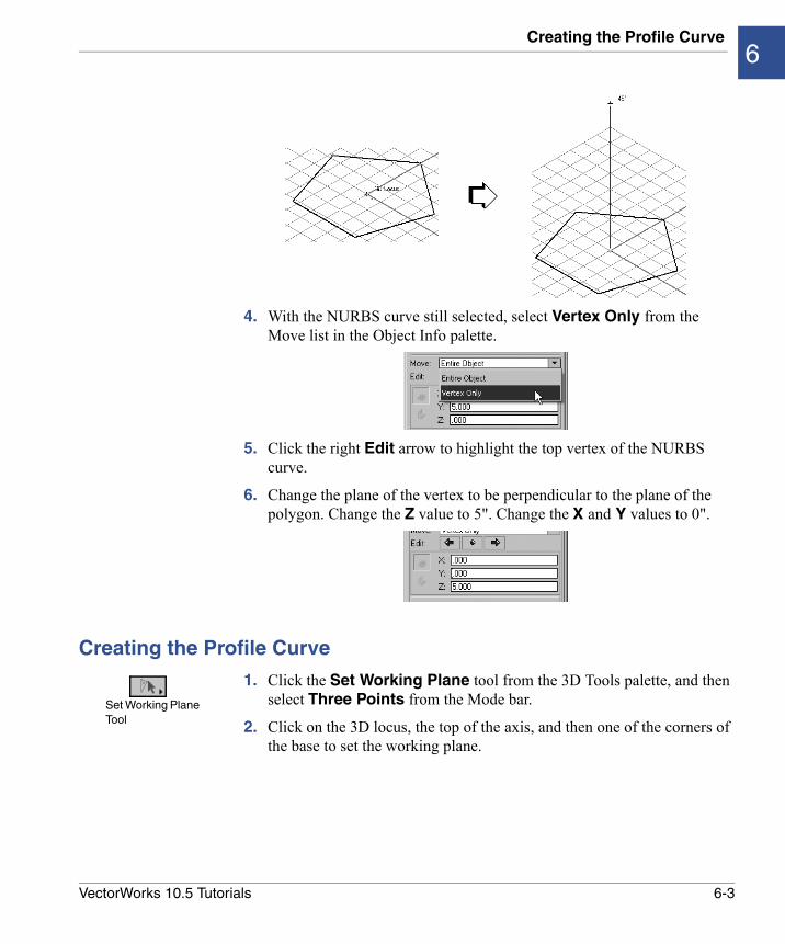
4. With the NURBS curve still selected, select Vertex Only from the Move list in the Object Info palette.
5. Click the right Edit arrow to highlight the top vertex of the NURBS curve.
6. Change the plane of the vertex to be perpendicular to the plane of the polygon. Change the Z value to 5". Change the X and Y values to 0".
Creating the Profile Curve
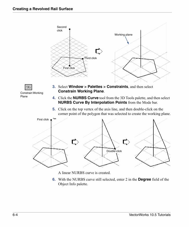
1. Click the Set Working Plane tool from the 3D Tools palette, and then select Three Points from the Mode bar.
2. Click on the 3D locus, the top of the axis, and then one of the corners of the base to set the working plane.
Set Working Plane Tool
6-3VectorWorks 10.5 Tutorials
Creating a Revolved Rail Surface
3. Select Window > Palettes > Constraints, and then select Constrain Working Plane.
4. Click the NURBS Curve tool from the 3D Tools palette, and then select NURBS Curve By Interpolation Points from the Mode bar.
5. Click on the top vertex of the axis line, and then double-click on the corner point of the polygon that was selected to create the working plane.
A linear NURBS curve is created.
6. With the NURBS curve still selected, enter 2 in the Degree field of the Object Info palette.
Second click
First click
Third click
Working plane
Constrain Working Plane
First click
Double-click
6-4 VectorWorks 10.5 Tutorials
Revolving Around a Rail6
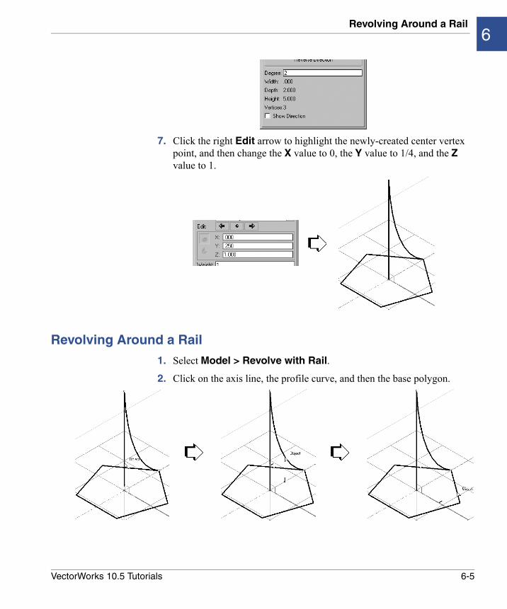
7. Click the right Edit arrow to highlight the newly-created center vertex point, and then change the X value to 0, the Y value to 1/4, and the Z value to 1.
Revolving Around a Rail
1. Select Model > Revolve with Rail.
2. Click on the axis line, the profile curve, and then the base polygon.
6-5VectorWorks 10.5 Tutorials
Creating a Revolved Rail Surface
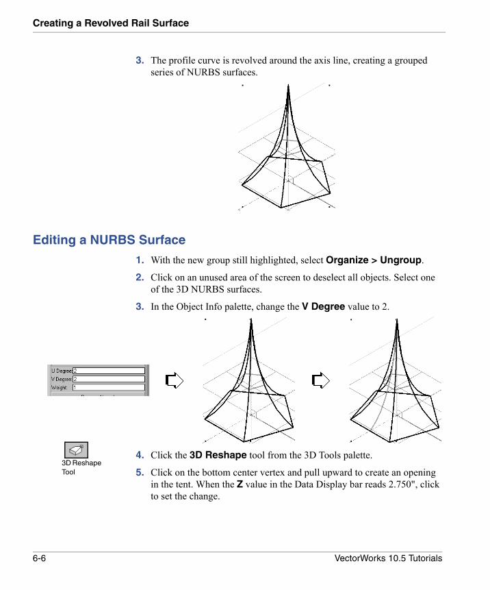
3. The profile curve is revolved around the axis line, creating a grouped series of NURBS surfaces.
Editing a NURBS Surface
1. With the new group still highlighted, select Organize > Ungroup.
2. Click on an unused area of the screen to deselect all objects. Select one of the 3D NURBS surfaces.
3. In the Object Info palette, change the V Degree value to 2.
4. Click the 3D Reshape tool from the 3D Tools palette.
5. Click on the bottom center vertex and pull upward to create an opening in the tent. When the Z value in the Data Display bar reads 2.750", click to set the change.
3D Reshape Tool
6-6 VectorWorks 10.5 Tutorials
Editing a NURBS Surface6
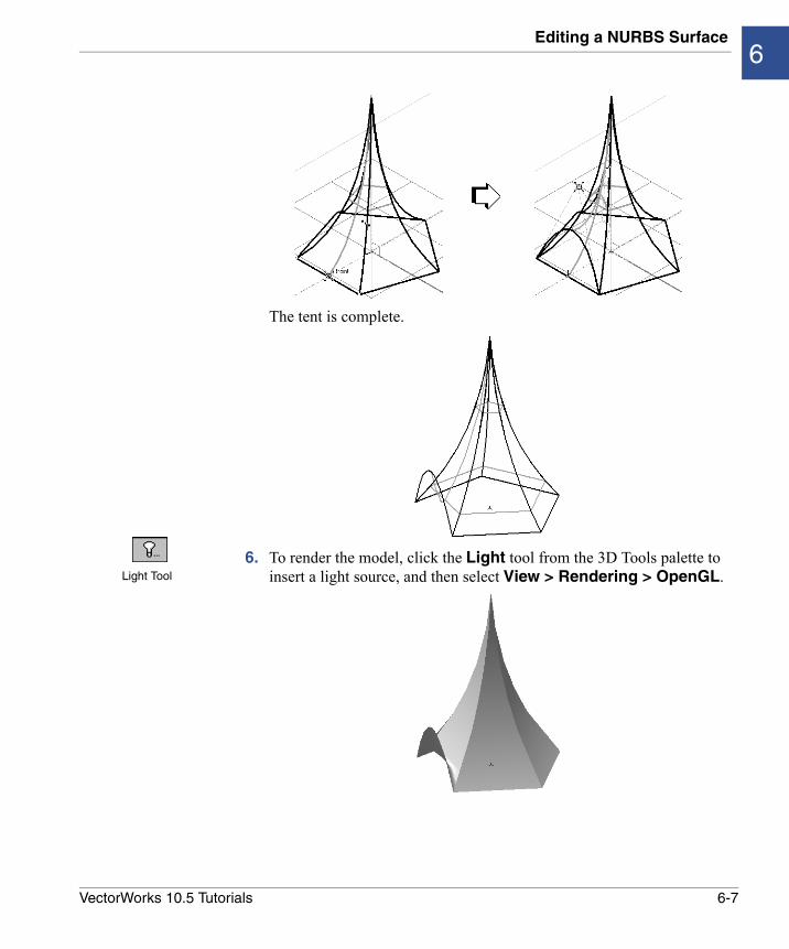
The tent is complete.
6. To render the model, click the Light tool from the 3D Tools palette to insert a light source, and then select View > Rendering > OpenGL.Light Tool
6-7VectorWorks 10.5 Tutorials
7
Creating Shapes by Extracting Curves and Lofting• Setting Up the Modeling Units
• Creating the Chair Shape
• Creating the Chair Padding
• Creating the Chair Frame
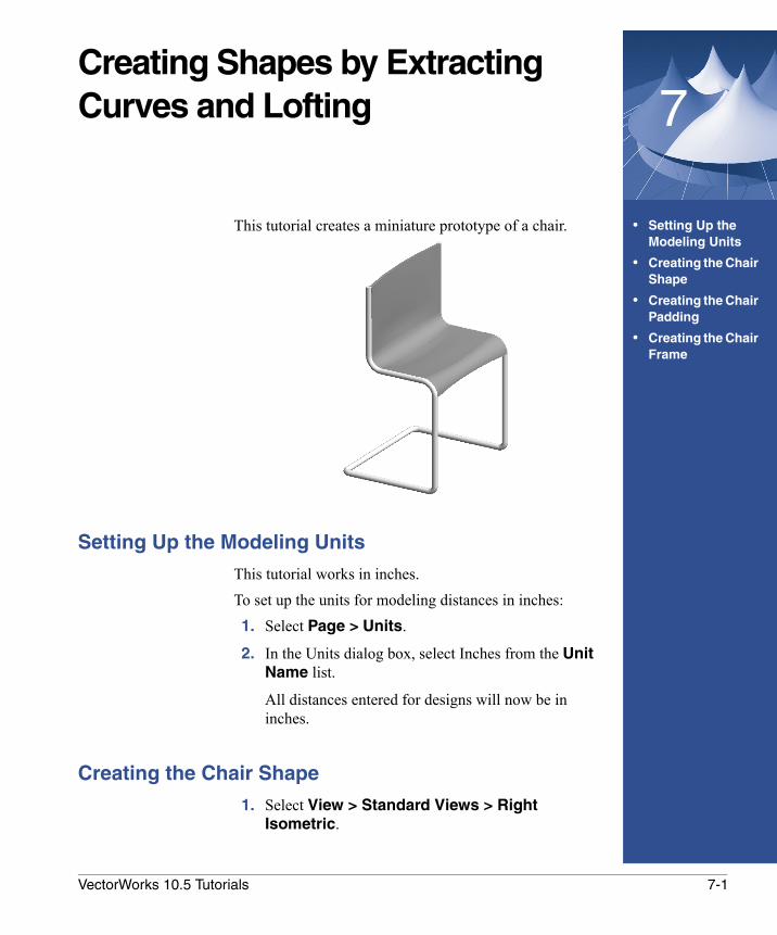
This tutorial creates a miniature prototype of a chair.
Setting Up the Modeling Units
This tutorial works in inches.To set up the units for modeling distances in inches: 1. Select Page > Units.
2. In the Units dialog box, select Inches from the Unit Name list.
All distances entered for designs will now be in inches.
Creating the Chair Shape
1. Select View > Standard Views > Right Isometric.
7-1VectorWorks 10.5 Tutorials
Creating Shapes by Extracting Curves and Lofting
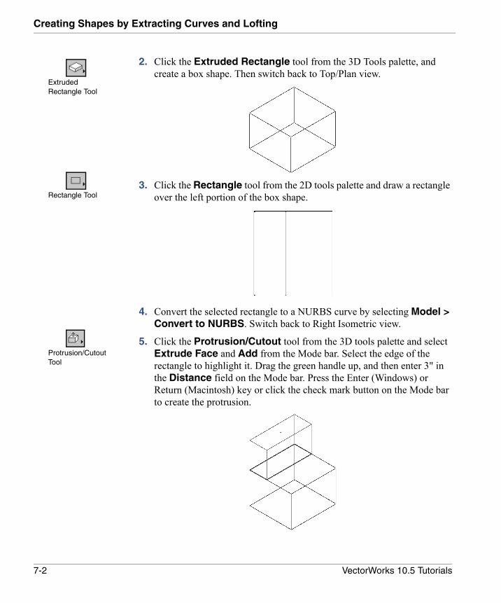
2. Click the Extruded Rectangle tool from the 3D Tools palette, and create a box shape. Then switch back to Top/Plan view.
3. Click the Rectangle tool from the 2D tools palette and draw a rectangle over the left portion of the box shape.
4. Convert the selected rectangle to a NURBS curve by selecting Model > Convert to NURBS. Switch back to Right Isometric view.
5. Click the Protrusion/Cutout tool from the 3D tools palette and select Extrude Face and Add from the Mode bar. Select the edge of the rectangle to highlight it. Drag the green handle up, and then enter 3" in the Distance field on the Mode bar. Press the Enter (Windows) or Return (Macintosh) key or click the check mark button on the Mode bar to create the protrusion.
Extruded Rectangle Tool
Rectangle Tool
Protrusion/Cutout Tool
7-2 VectorWorks 10.5 Tutorials
Creating the Chair Shape7
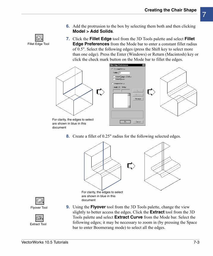
6. Add the protrusion to the box by selecting them both and then clicking Model > Add Solids.
7. Click the Fillet Edge tool from the 3D Tools palette and select Fillet Edge Preferences from the Mode bar to enter a constant fillet radius of 0.5". Select the following edges (press the Shift key to select more than one edge). Press the Enter (Windows) or Return (Macintosh) key or click the check mark button on the Mode bar to fillet the edges.
8. Create a fillet of 0.25" radius for the following selected edges.
9. Using the Flyover tool from the 3D Tools palette, change the view slightly to better access the edges. Click the Extract tool from the 3D Tools palette and select Extract Curve from the Mode bar. Select the following edges; it may be necessary to zoom in (by pressing the Space bar to enter Boomerang mode) to select all the edges.
Fillet Edge Tool
For clarity, the edges to select are shown in blue in this document
For clarity, the edges to select are shown in blue in this document
Flyover Tool
Extract Tool
7-3VectorWorks 10.5 Tutorials
Creating Shapes by Extracting Curves and Lofting
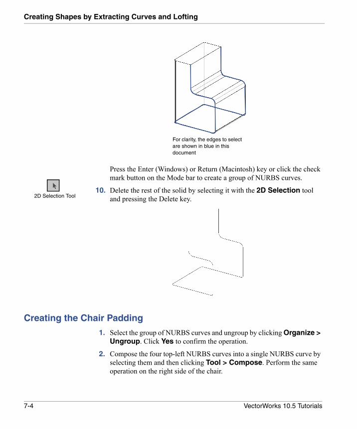
Press the Enter (Windows) or Return (Macintosh) key or click the check mark button on the Mode bar to create a group of NURBS curves.
10. Delete the rest of the solid by selecting it with the 2D Selection tool and pressing the Delete key.
Creating the Chair Padding
1. Select the group of NURBS curves and ungroup by clicking Organize > Ungroup. Click Yes to confirm the operation.
2. Compose the four top-left NURBS curves into a single NURBS curve by selecting them and then clicking Tool > Compose. Perform the same operation on the right side of the chair.
For clarity, the edges to select are shown in blue in this document
2D Selection Tool
7-4 VectorWorks 10.5 Tutorials
Creating the Chair Padding7
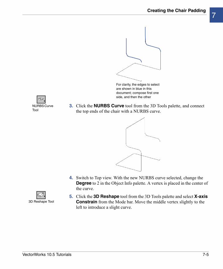
3. Click the NURBS Curve tool from the 3D Tools palette, and connect the top ends of the chair with a NURBS curve.
4. Switch to Top view. With the new NURBS curve selected, change the Degree to 2 in the Object Info palette. A vertex is placed in the center of the curve.
5. Click the 3D Reshape tool from the 3D Tools palette and select X-axis Constrain from the Mode bar. Move the middle vertex slightly to the left to introduce a slight curve.
For clarity, the edges to select are shown in blue in this document; compose first one side, and then the other
NURBS Curve Tool
3D Reshape Tool
7-5VectorWorks 10.5 Tutorials
Creating Shapes by Extracting Curves and Lofting
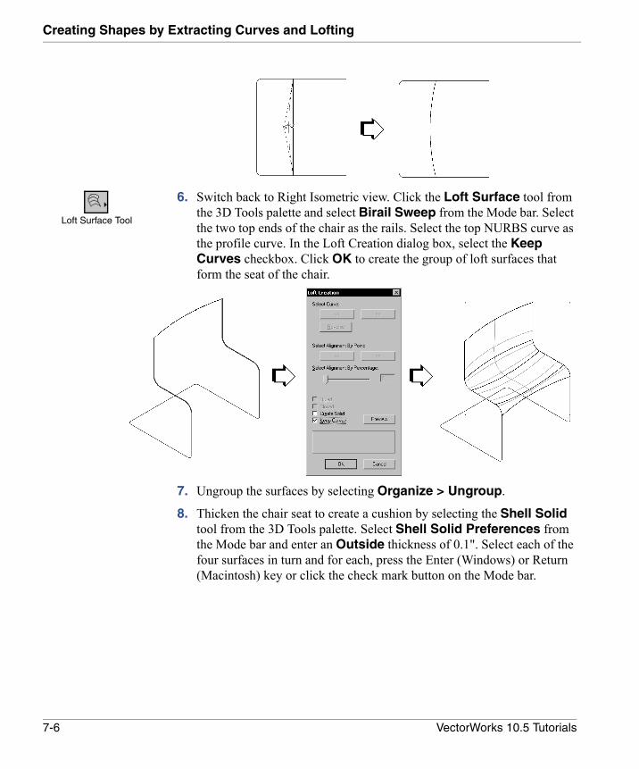
6. Switch back to Right Isometric view. Click the Loft Surface tool from the 3D Tools palette and select Birail Sweep from the Mode bar. Select the two top ends of the chair as the rails. Select the top NURBS curve as the profile curve. In the Loft Creation dialog box, select the Keep Curves checkbox. Click OK to create the group of loft surfaces that form the seat of the chair.
7. Ungroup the surfaces by selecting Organize > Ungroup.
8. Thicken the chair seat to create a cushion by selecting the Shell Solid tool from the 3D Tools palette. Select Shell Solid Preferences from the Mode bar and enter an Outside thickness of 0.1". Select each of the four surfaces in turn and for each, press the Enter (Windows) or Return (Macintosh) key or click the check mark button on the Mode bar.
Loft Surface Tool
7-6 VectorWorks 10.5 Tutorials
Creating the Chair Frame7
Creating the Chair Frame
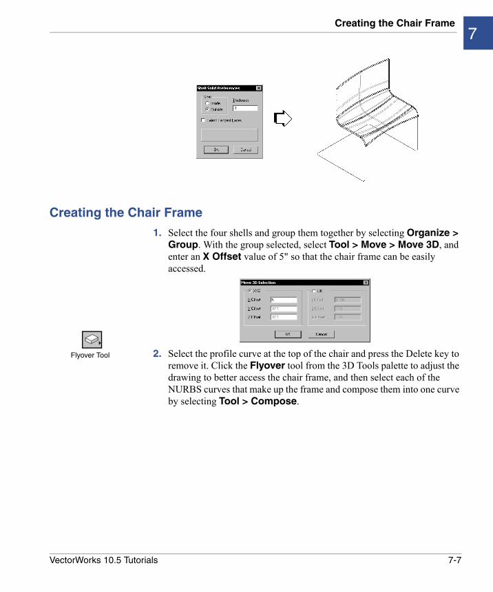
1. Select the four shells and group them together by selecting Organize > Group. With the group selected, select Tool > Move > Move 3D, and enter an X Offset value of 5" so that the chair frame can be easily accessed.
2. Select the profile curve at the top of the chair and press the Delete key to remove it. Click the Flyover tool from the 3D Tools palette to adjust the drawing to better access the chair frame, and then select each of the NURBS curves that make up the frame and compose them into one curve by selecting Tool > Compose.
Flyover Tool
7-7VectorWorks 10.5 Tutorials
Creating Shapes by Extracting Curves and Lofting
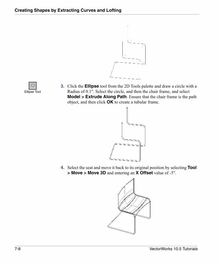
3. Click the Ellipse tool from the 2D Tools palette and draw a circle with a Radius of 0.1". Select the circle, and then the chair frame, and select Model > Extrude Along Path. Ensure that the chair frame is the path object, and then click OK to create a tubular frame.
4. Select the seat and move it back to its original position by selecting Tool > Move > Move 3D and entering an X Offset value of -5".
Ellipse Tool
7-8 VectorWorks 10.5 Tutorials
Creating the Chair Frame7
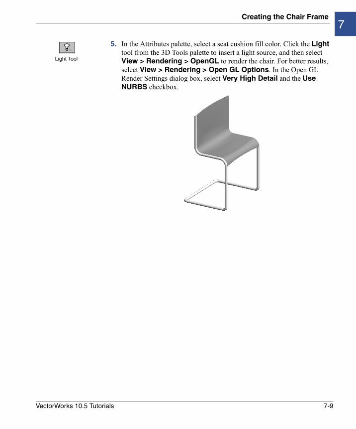
5. In the Attributes palette, select a seat cushion fill color. Click the Light tool from the 3D Tools palette to insert a light source, and then select View > Rendering > OpenGL to render the chair. For better results, select View > Rendering > Open GL Options. In the Open GL Render Settings dialog box, select Very High Detail and the Use NURBS checkbox.
Light Tool
7-9VectorWorks 10.5 Tutorials
8
Creating a Solid by Sweeping, Extruding, and Shelling• Getting Started
• Setting Up the Modeling Units
• Creating the 2D Elements
• Creating the Can with Sweeps and Extrudes
• Adding Design Details
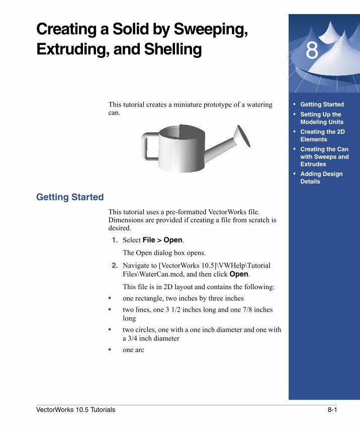
This tutorial creates a miniature prototype of a watering can.
Getting Started
This tutorial uses a pre-formatted VectorWorks file. Dimensions are provided if creating a file from scratch is desired.1. Select File > Open.
The Open dialog box opens.
2. Navigate to [VectorWorks 10.5]\VWHelp\Tutorial Files\WaterCan.mcd, and then click Open.
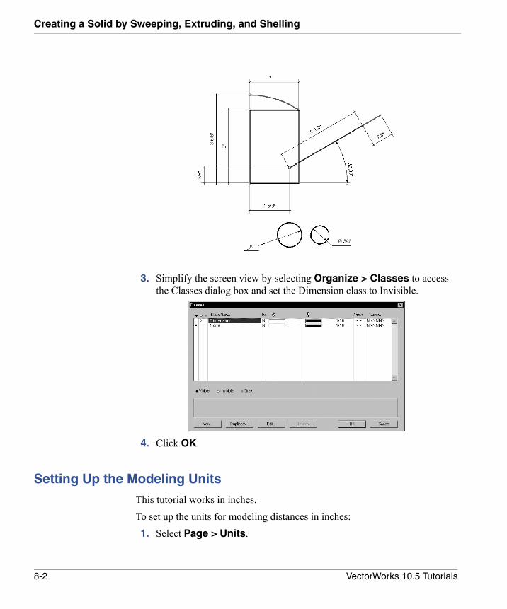
This file is in 2D layout and contains the following:• one rectangle, two inches by three inches• two lines, one 3 1/2 inches long and one 7/8 inches
long• two circles, one with a one inch diameter and one with
a 3/4 inch diameter• one arc
8-1VectorWorks 10.5 Tutorials
Creating a Solid by Sweeping, Extruding, and Shelling
3. Simplify the screen view by selecting Organize > Classes to access the Classes dialog box and set the Dimension class to Invisible.
4. Click OK.
Setting Up the Modeling Units
This tutorial works in inches.To set up the units for modeling distances in inches: 1. Select Page > Units.
8-2 VectorWorks 10.5 Tutorials
Creating the 2D Elements8
2. In the Units dialog box, select Inches from the Unit Name list.
All distances entered for designs will now be in inches.
Creating the 2D Elements
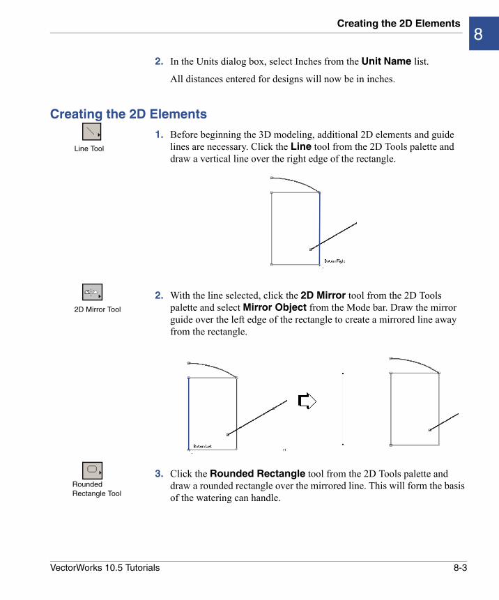
1. Before beginning the 3D modeling, additional 2D elements and guide lines are necessary. Click the Line tool from the 2D Tools palette and draw a vertical line over the right edge of the rectangle.
2. With the line selected, click the 2D Mirror tool from the 2D Tools palette and select Mirror Object from the Mode bar. Draw the mirror guide over the left edge of the rectangle to create a mirrored line away from the rectangle.
3. Click the Rounded Rectangle tool from the 2D Tools palette and draw a rounded rectangle over the mirrored line. This will form the basis of the watering can handle.
Line Tool
2D Mirror Tool
Rounded Rectangle Tool
8-3VectorWorks 10.5 Tutorials
Creating a Solid by Sweeping, Extruding, and Shelling
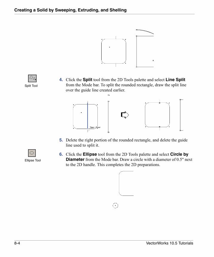
4. Click the Split tool from the 2D Tools palette and select Line Split from the Mode bar. To split the rounded rectangle, draw the split line over the guide line created earlier.
5. Delete the right portion of the rounded rectangle, and delete the guide line used to split it.
6. Click the Ellipse tool from the 2D Tools palette and select Circle by Diameter from the Mode bar. Draw a circle with a diameter of 0.5" next to the 2D handle. This completes the 2D preparations.
Split Tool
Ellipse Tool
8-4 VectorWorks 10.5 Tutorials
Creating the Can with Sweeps and Extrudes8
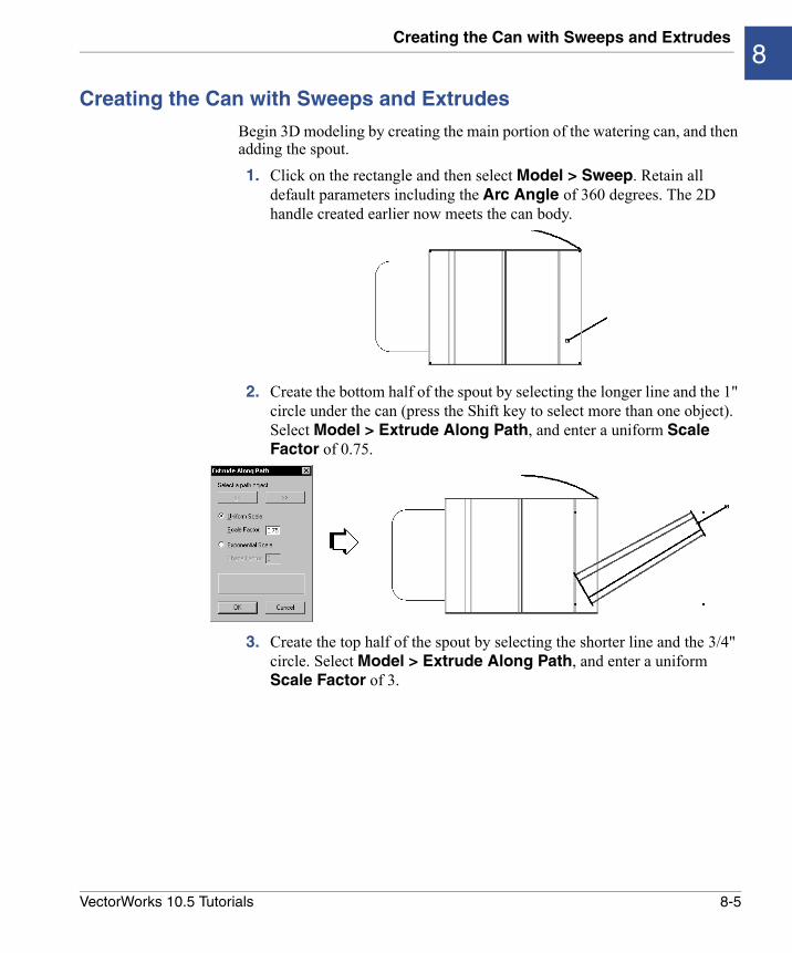
Creating the Can with Sweeps and Extrudes
Begin 3D modeling by creating the main portion of the watering can, and then adding the spout.1. Click on the rectangle and then select Model > Sweep. Retain all
default parameters including the Arc Angle of 360 degrees. The 2D handle created earlier now meets the can body.
2. Create the bottom half of the spout by selecting the longer line and the 1" circle under the can (press the Shift key to select more than one object). Select Model > Extrude Along Path, and enter a uniform Scale Factor of 0.75.
3. Create the top half of the spout by selecting the shorter line and the 3/4" circle. Select Model > Extrude Along Path, and enter a uniform Scale Factor of 3.
8-5VectorWorks 10.5 Tutorials
Creating a Solid by Sweeping, Extruding, and Shelling
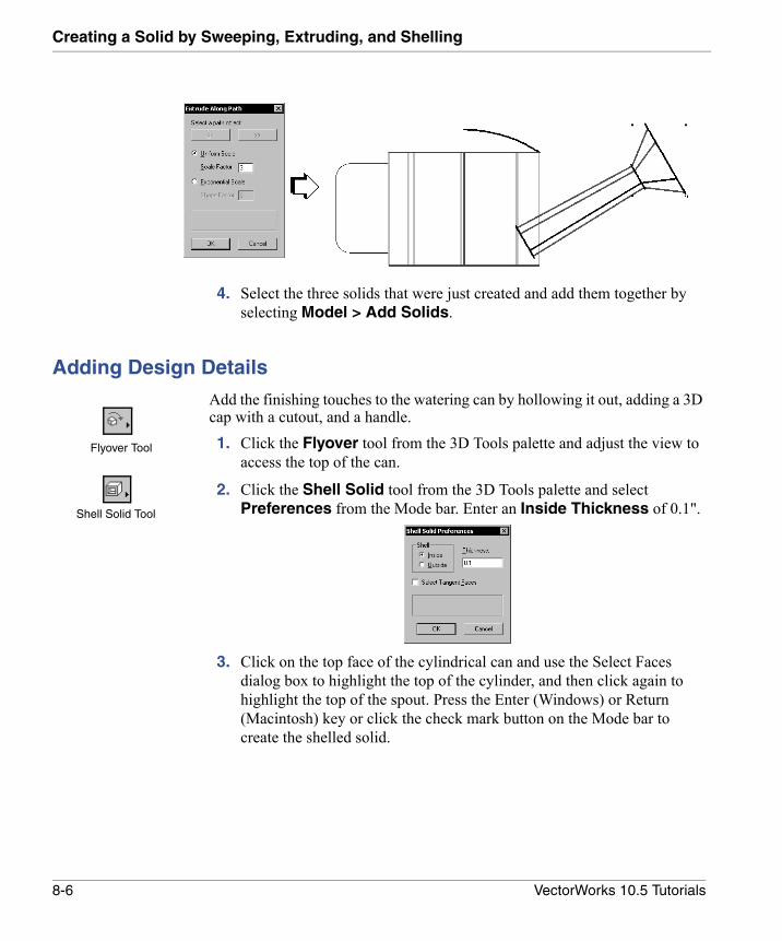
4. Select the three solids that were just created and add them together by selecting Model > Add Solids.
Adding Design Details
Add the finishing touches to the watering can by hollowing it out, adding a 3D cap with a cutout, and a handle.1. Click the Flyover tool from the 3D Tools palette and adjust the view to
access the top of the can.
2. Click the Shell Solid tool from the 3D Tools palette and select Preferences from the Mode bar. Enter an Inside Thickness of 0.1".
3. Click on the top face of the cylindrical can and use the Select Faces dialog box to highlight the top of the cylinder, and then click again to highlight the top of the spout. Press the Enter (Windows) or Return (Macintosh) key or click the check mark button on the Mode bar to create the shelled solid.
Flyover Tool
Shell Solid Tool
8-6 VectorWorks 10.5 Tutorials

Adding Design Details8
4. Switch the view to Top/Plan by selecting View > Standard Views > Top⁄Plan. Select the arc at the top of the can, and select Model > Sweep. Retain the default values in the Create Sweep dialog box and click OK to create a 360 degree angle sweep.
5. Convert the sweep into a NURBS surface by selecting Model > Convert to NURBS.
6. Shell the cap by clicking the Shell Solid tool from the 3D Tools palette. Use the same Inside Thickness of 0.1". Click on the cap and then press the Enter (Windows) or Return (Macintosh) key or click the check mark button on the Mode bar to create the shelled solid.
7. Add the cap to the rest of the solid by selecting both and selecting Model > Add Solids.
8. Now create an opening in the cap. Select View > Standard Views > Front.
Shell Solid Tool
8-7VectorWorks 10.5 Tutorials
Creating a Solid by Sweeping, Extruding, and Shelling
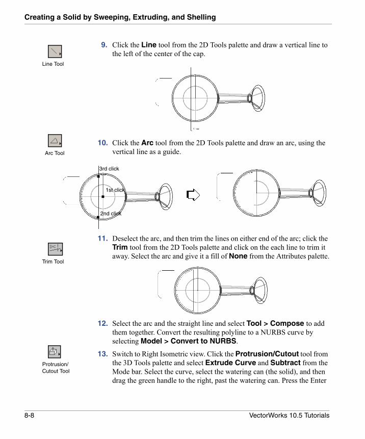
9. Click the Line tool from the 2D Tools palette and draw a vertical line to the left of the center of the cap.
10. Click the Arc tool from the 2D Tools palette and draw an arc, using the vertical line as a guide.
11. Deselect the arc, and then trim the lines on either end of the arc; click the Trim tool from the 2D Tools palette and click on the each line to trim it away. Select the arc and give it a fill of None from the Attributes palette.
‘
12. Select the arc and the straight line and select Tool > Compose to add them together. Convert the resulting polyline to a NURBS curve by selecting Model > Convert to NURBS.
13. Switch to Right Isometric view. Click the Protrusion/Cutout tool from the 3D Tools palette and select Extrude Curve and Subtract from the Mode bar. Select the curve, select the watering can (the solid), and then drag the green handle to the right, past the watering can. Press the Enter
Line Tool
Arc Tool
1st click
3rd click
2nd click
Trim Tool
Protrusion/Cutout Tool
8-8 VectorWorks 10.5 Tutorials
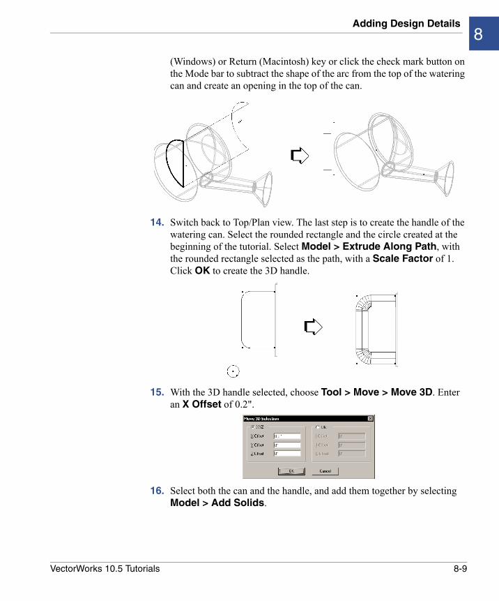
Adding Design Details8
(Windows) or Return (Macintosh) key or click the check mark button on the Mode bar to subtract the shape of the arc from the top of the watering can and create an opening in the top of the can.
14. Switch back to Top/Plan view. The last step is to create the handle of the watering can. Select the rounded rectangle and the circle created at the beginning of the tutorial. Select Model > Extrude Along Path, with the rounded rectangle selected as the path, with a Scale Factor of 1. Click OK to create the 3D handle.
15. With the 3D handle selected, choose Tool > Move > Move 3D. Enter an X Offset of 0.2".
16. Select both the can and the handle, and add them together by selecting Model > Add Solids.
8-9VectorWorks 10.5 Tutorials
Creating a Solid by Sweeping, Extruding, and Shelling
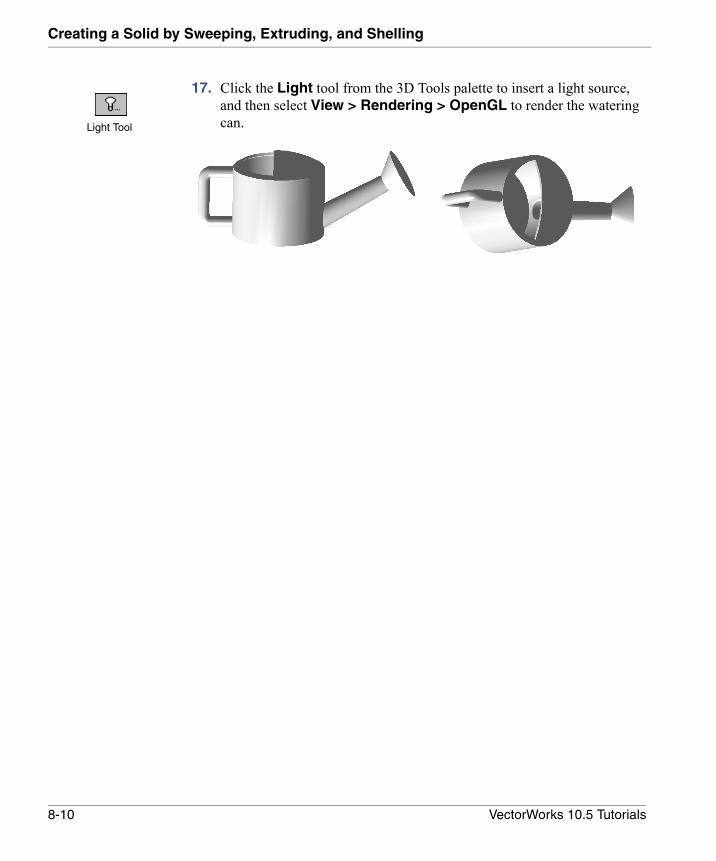
17. Click the Light tool from the 3D Tools palette to insert a light source, and then select View > Rendering > OpenGL to render the watering can.Light Tool
8-10 VectorWorks 10.5 Tutorials
9
Creating Helix-spiral Objects• Getting Started
• Setting Up the Modeling Units
• Creating the Doorstopper Body with Helix-spiral Objects
• Extruding the Doorstopper Body Along a Path
• Creating the Doorstopper Head with Sweeps and Filleted Edges
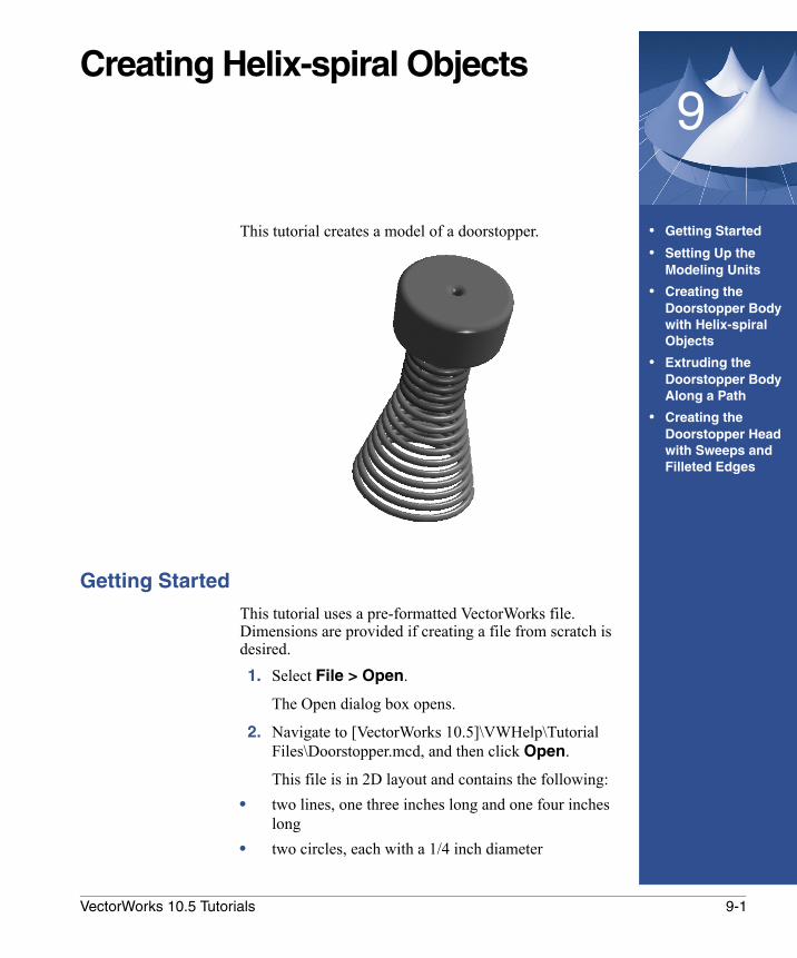
This tutorial creates a model of a doorstopper.
Getting Started
This tutorial uses a pre-formatted VectorWorks file. Dimensions are provided if creating a file from scratch is desired.1. Select File > Open.
The Open dialog box opens.
2. Navigate to [VectorWorks 10.5]\VWHelp\Tutorial Files\Doorstopper.mcd, and then click Open.
This file is in 2D layout and contains the following:• two lines, one three inches long and one four inches
long• two circles, each with a 1/4 inch diameter
9-1VectorWorks 10.5 Tutorials
Creating Helix-spiral Objects
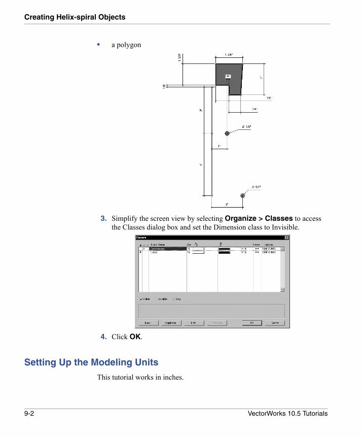
• a polygon
3. Simplify the screen view by selecting Organize > Classes to access the Classes dialog box and set the Dimension class to Invisible.
4. Click OK.
Setting Up the Modeling Units
This tutorial works in inches.
9-2 VectorWorks 10.5 Tutorials
Creating the Doorstopper Body with Helix-spiral Objects9
To set up the units for modeling distances in inches: 1. Select Page > Units.
2. In the Units dialog box, select Inches from the Unit Name list.
All distances entered for designs will now be in inches.
Creating the Doorstopper Body with Helix-spiral Objects
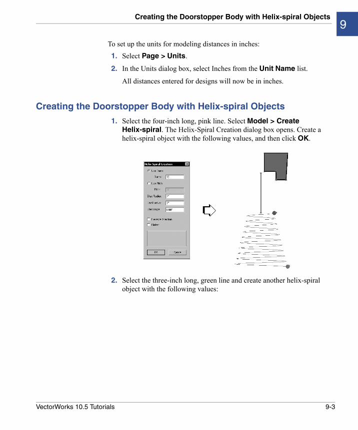
1. Select the four-inch long, pink line. Select Model > Create Helix-spiral. The Helix-Spiral Creation dialog box opens. Create a helix-spiral object with the following values, and then click OK.
2. Select the three-inch long, green line and create another helix-spiral object with the following values:
9-3VectorWorks 10.5 Tutorials
Creating Helix-spiral Objects
Extruding the Doorstopper Body Along a Path
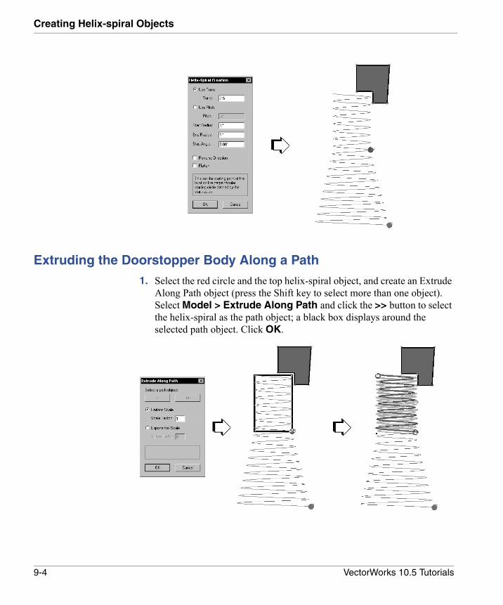
1. Select the red circle and the top helix-spiral object, and create an Extrude Along Path object (press the Shift key to select more than one object). Select Model > Extrude Along Path and click the >> button to select the helix-spiral as the path object; a black box displays around the selected path object. Click OK.
9-4 VectorWorks 10.5 Tutorials
Creating the Doorstopper Head with Sweeps and Filleted Edges9
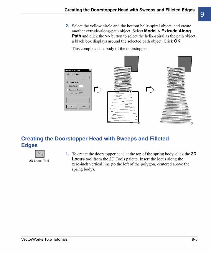
2. Select the yellow circle and the bottom helix-spiral object, and create another extrude-along-path object. Select Model > Extrude Along Path and click the >> button to select the helix-spiral as the path object; a black box displays around the selected path object. Click OK.
This completes the body of the doorstopper.
Creating the Doorstopper Head with Sweeps and Filleted Edges
1. To create the doorstopper head at the top of the spring body, click the 2D Locus tool from the 2D Tools palette. Insert the locus along the zero-inch vertical line (to the left of the polygon, centered above the spring body).
2D Locus Tool
9-5VectorWorks 10.5 Tutorials
Creating Helix-spiral Objects
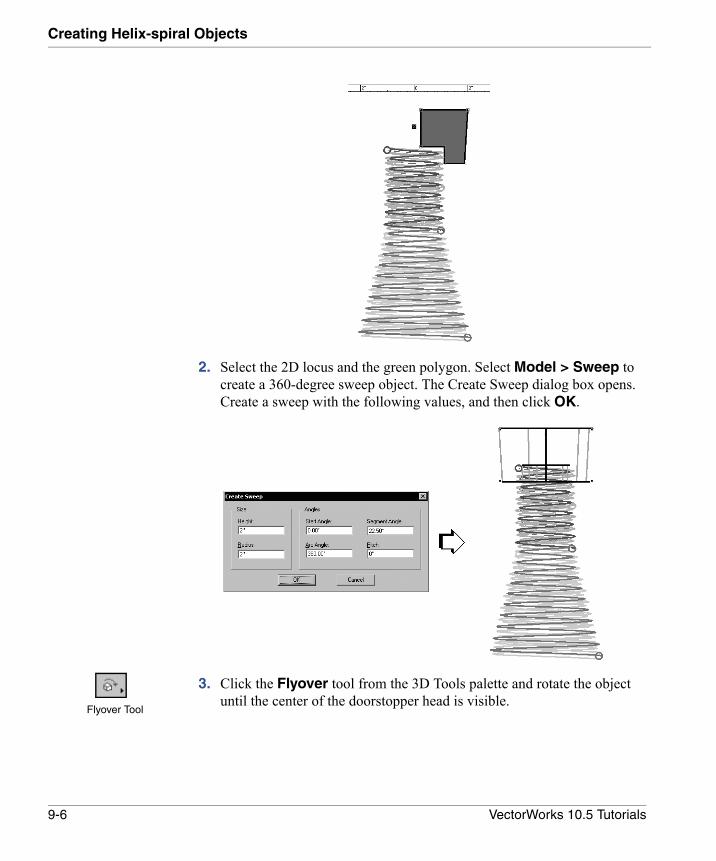
2. Select the 2D locus and the green polygon. Select Model > Sweep to create a 360-degree sweep object. The Create Sweep dialog box opens. Create a sweep with the following values, and then click OK.
3. Click the Flyover tool from the 3D Tools palette and rotate the object until the center of the doorstopper head is visible.
Flyover Tool
9-6 VectorWorks 10.5 Tutorials

Creating the Doorstopper Head with Sweeps and Filleted Edges9
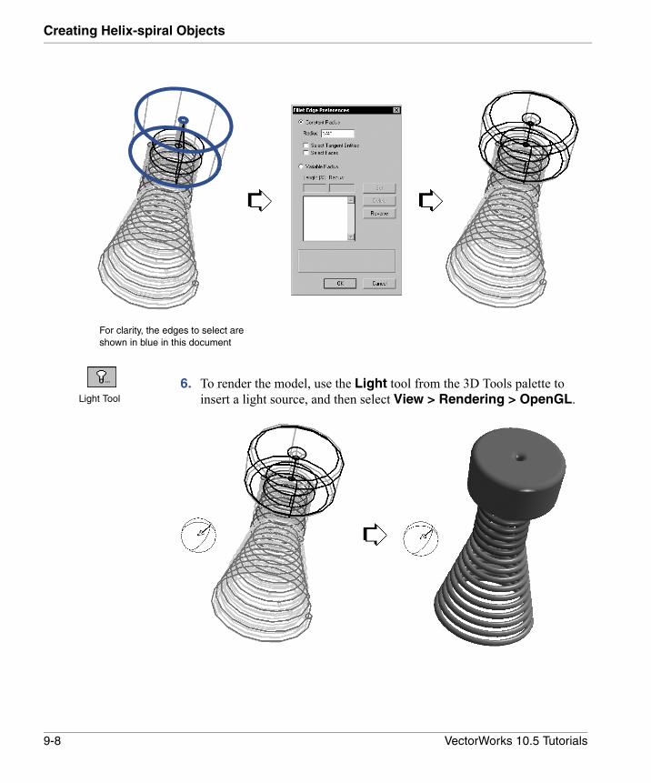
4. Click the Fillet Edge tool from the 3D Tools palette. Click the top edge of the stopper. Enter a 1/4" Radius in the Fillet Edge Preferences dialog box, and then click OK. (If necessary, select Fillet Edge Preferences from the Mode bar to display the Fillet Edge Preferences dialog box.)
5. Select the top two edges and the bottom edge of the doorstopper head. Once all edges are selected, press Enter (Windows) or Return (Macintosh) or click the check mark button on the Mode bar. The edges of the doorstopper head are filleted and the doorstopper is complete.
Fillet Edge Tool
9-7VectorWorks 10.5 Tutorials
Creating Helix-spiral Objects
6. To render the model, use the Light tool from the 3D Tools palette to insert a light source, and then select View > Rendering > OpenGL.
For clarity, the edges to select are shown in blue in this document
Light Tool
9-8 VectorWorks 10.5 Tutorials
10
Creating Protrusions and RibsIn this Chapter:
• Getting Started
• Setting Up the Modeling Units
• Organizing Objects
• Creating Guide Lines
• Creating the Base Protrusion
• Creating More Protrusions
• Creating the 3D Wireframe
• Mirroring the Protrusion
• Creating Ribs
• Mirroring the Ribs
• Adding the Solids
• Creating Slanted Ribs
• Mirroring the Slanted Ribs
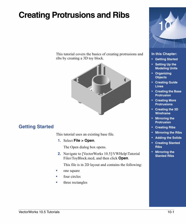
This tutorial covers the basics of creating protrusions and ribs by creating a 3D toy block.
Getting Started
This tutorial uses an existing base file.1. Select File > Open.
The Open dialog box opens.
2. Navigate to [VectorWorks 10.5]\VWHelp\Tutorial Files\ToyBlock.mcd, and then click Open.
This file is in 2D layout and contains the following:• one square• four circles• three rectangles
10-1VectorWorks 10.5 Tutorials
Creating Protrusions and Ribs
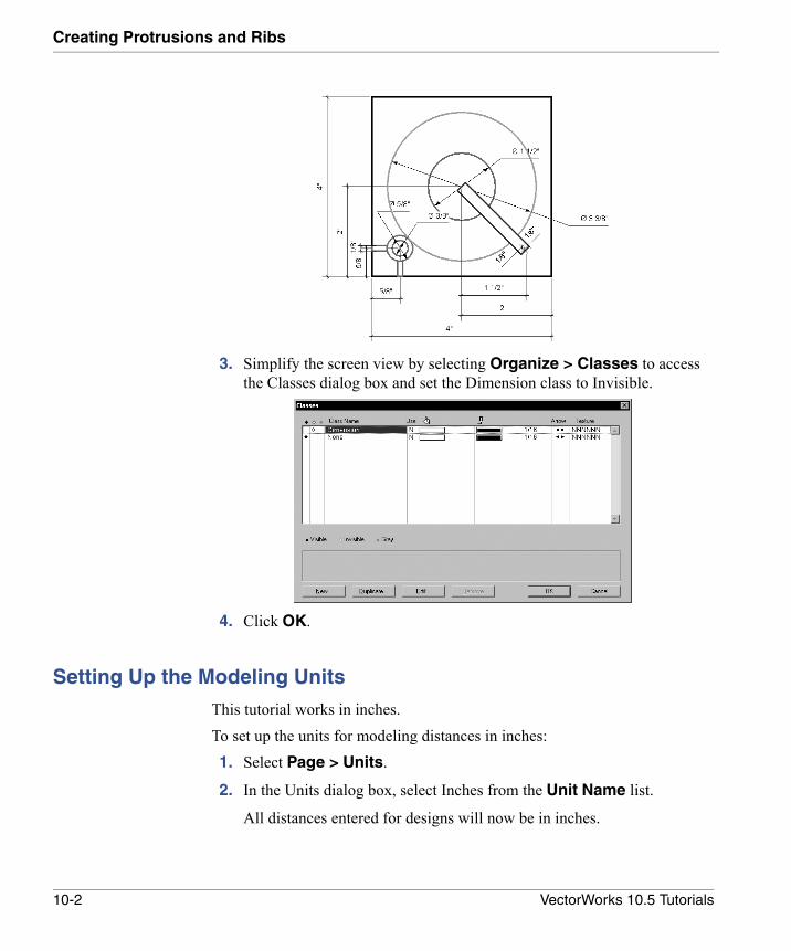
3. Simplify the screen view by selecting Organize > Classes to access the Classes dialog box and set the Dimension class to Invisible.
4. Click OK.
Setting Up the Modeling Units
This tutorial works in inches.To set up the units for modeling distances in inches: 1. Select Page > Units.
2. In the Units dialog box, select Inches from the Unit Name list.
All distances entered for designs will now be in inches.
10-2 VectorWorks 10.5 Tutorials
Organizing Objects10
Organizing Objects
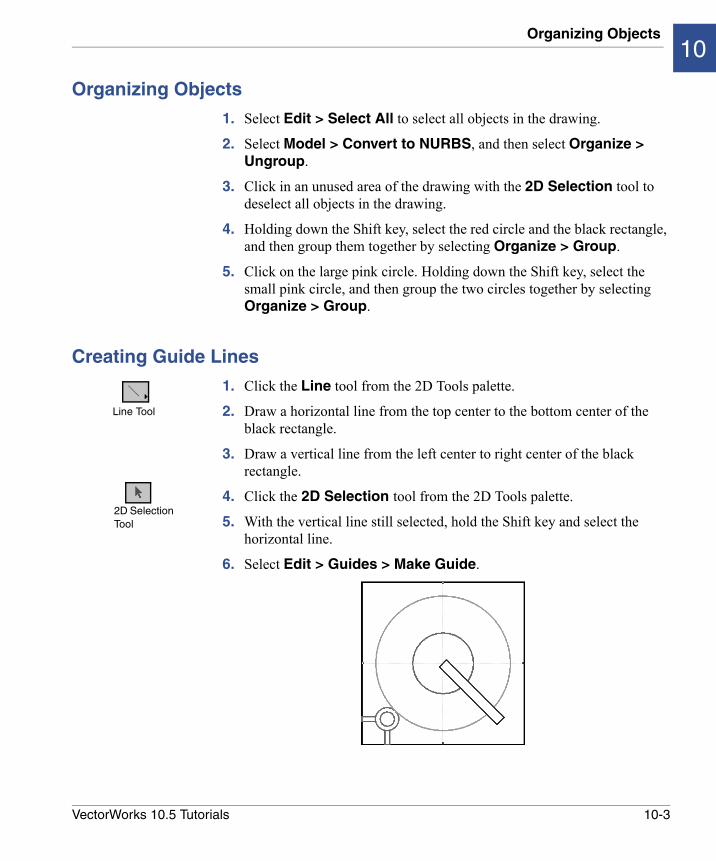
1. Select Edit > Select All to select all objects in the drawing.
2. Select Model > Convert to NURBS, and then select Organize > Ungroup.
3. Click in an unused area of the drawing with the 2D Selection tool to deselect all objects in the drawing.
4. Holding down the Shift key, select the red circle and the black rectangle, and then group them together by selecting Organize > Group.
5. Click on the large pink circle. Holding down the Shift key, select the small pink circle, and then group the two circles together by selecting Organize > Group.
Creating Guide Lines
1. Click the Line tool from the 2D Tools palette.
2. Draw a horizontal line from the top center to the bottom center of the black rectangle.
3. Draw a vertical line from the left center to right center of the black rectangle.
4. Click the 2D Selection tool from the 2D Tools palette.
5. With the vertical line still selected, hold the Shift key and select the horizontal line.
6. Select Edit > Guides > Make Guide.
Line Tool
2D Selection Tool
10-3VectorWorks 10.5 Tutorials
Creating Protrusions and Ribs
7. Select Edit > Guides > Hide Guides to temporarily hide the guide lines.
Creating the Base Protrusion
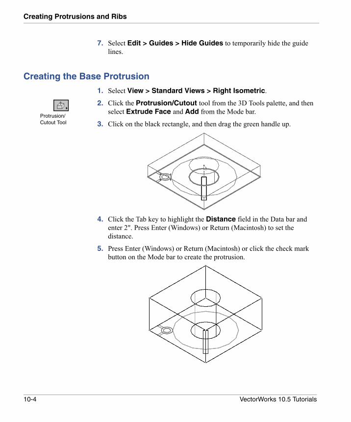
1. Select View > Standard Views > Right Isometric.
2. Click the Protrusion/Cutout tool from the 3D Tools palette, and then select Extrude Face and Add from the Mode bar.
3. Click on the black rectangle, and then drag the green handle up.
4. Click the Tab key to highlight the Distance field in the Data bar and enter 2". Press Enter (Windows) or Return (Macintosh) to set the distance.
5. Press Enter (Windows) or Return (Macintosh) or click the check mark button on the Mode bar to create the protrusion.
Protrusion/Cutout Tool
10-4 VectorWorks 10.5 Tutorials
Creating the Base Protrusion10
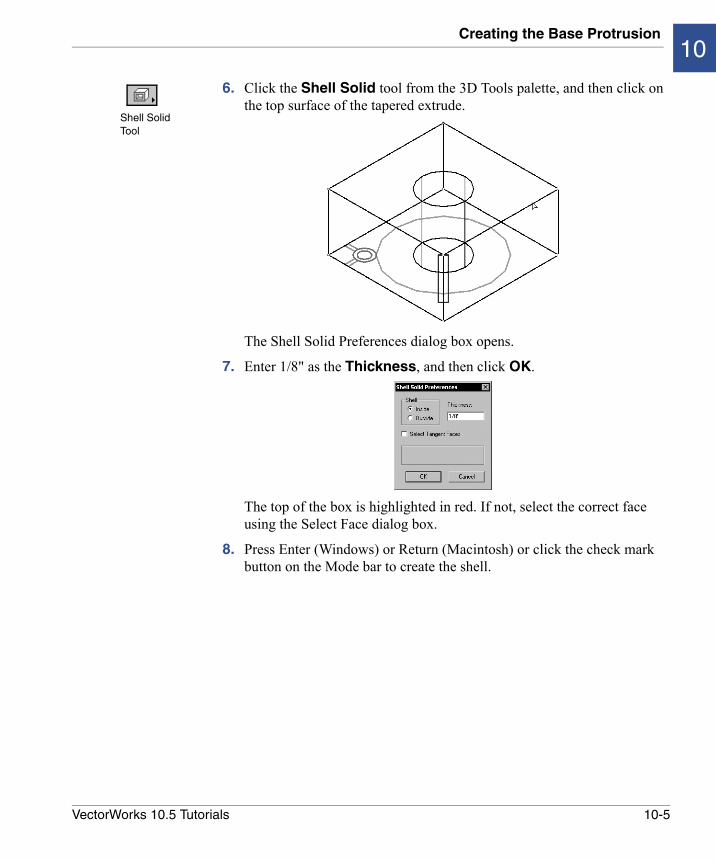
6. Click the Shell Solid tool from the 3D Tools palette, and then click on the top surface of the tapered extrude.
The Shell Solid Preferences dialog box opens.
7. Enter 1/8" as the Thickness, and then click OK.
The top of the box is highlighted in red. If not, select the correct face using the Select Face dialog box.
8. Press Enter (Windows) or Return (Macintosh) or click the check mark button on the Mode bar to create the shell.
Shell Solid Tool
10-5VectorWorks 10.5 Tutorials
Creating Protrusions and Ribs
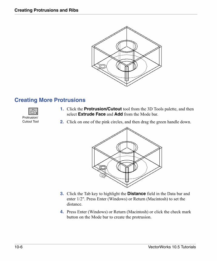
Creating More Protrusions
1. Click the Protrusion/Cutout tool from the 3D Tools palette, and then select Extrude Face and Add from the Mode bar.
2. Click on one of the pink circles, and then drag the green handle down.
3. Click the Tab key to highlight the Distance field in the Data bar and enter 1/2". Press Enter (Windows) or Return (Macintosh) to set the distance.
4. Press Enter (Windows) or Return (Macintosh) or click the check mark button on the Mode bar to create the protrusion.
Protrusion/Cutout Tool
10-6 VectorWorks 10.5 Tutorials
Creating the 3D Wireframe10
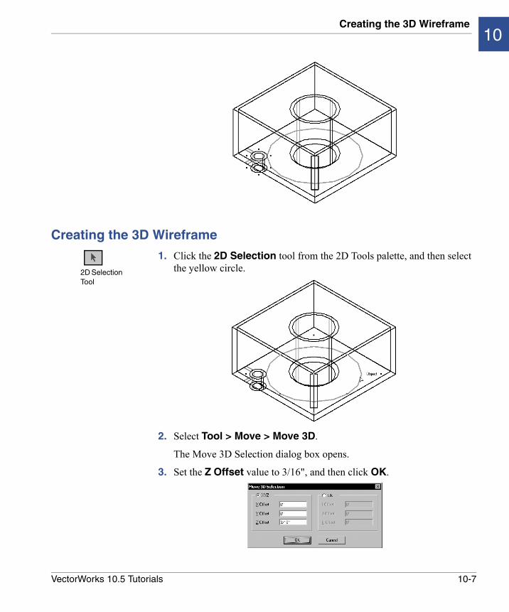
Creating the 3D Wireframe
1. Click the 2D Selection tool from the 2D Tools palette, and then select the yellow circle.
2. Select Tool > Move > Move 3D.
The Move 3D Selection dialog box opens.
3. Set the Z Offset value to 3/16", and then click OK.
2D Selection Tool
10-7VectorWorks 10.5 Tutorials
Creating Protrusions and Ribs
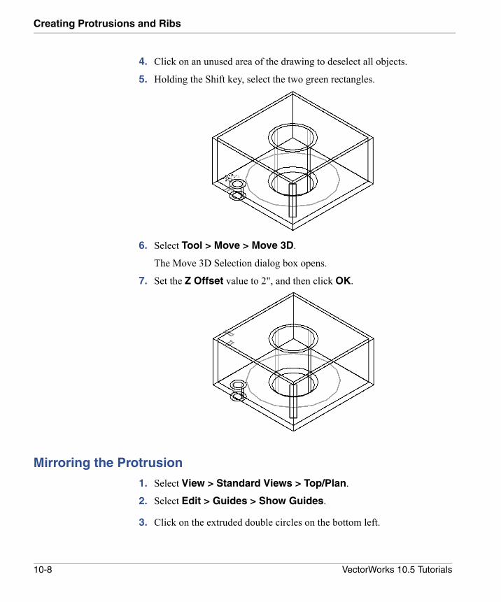
4. Click on an unused area of the drawing to deselect all objects.
5. Holding the Shift key, select the two green rectangles.
6. Select Tool > Move > Move 3D.
The Move 3D Selection dialog box opens.
7. Set the Z Offset value to 2", and then click OK.
Mirroring the Protrusion
1. Select View > Standard Views > Top/Plan.
2. Select Edit > Guides > Show Guides.
3. Click on the extruded double circles on the bottom left.
10-8 VectorWorks 10.5 Tutorials
Mirroring the Protrusion10
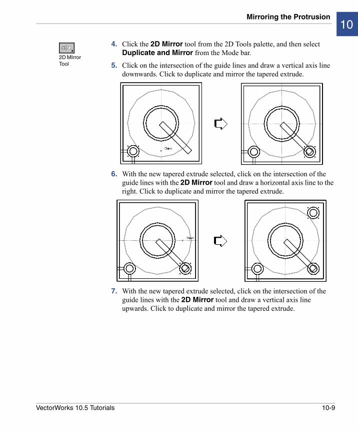
4. Click the 2D Mirror tool from the 2D Tools palette, and then select Duplicate and Mirror from the Mode bar.
5. Click on the intersection of the guide lines and draw a vertical axis line downwards. Click to duplicate and mirror the tapered extrude.
6. With the new tapered extrude selected, click on the intersection of the guide lines with the 2D Mirror tool and draw a horizontal axis line to the right. Click to duplicate and mirror the tapered extrude.
7. With the new tapered extrude selected, click on the intersection of the guide lines with the 2D Mirror tool and draw a vertical axis line upwards. Click to duplicate and mirror the tapered extrude.
2D MIrror Tool
10-9VectorWorks 10.5 Tutorials
Creating Protrusions and Ribs
8. Select Edit > Guides > Hide Guides.
Creating Ribs
1. Select View > Standard Views > Right Isometric.
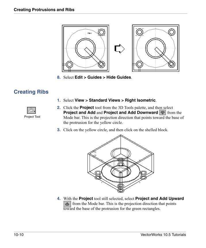
2. Click the Project tool from the 3D Tools palette, and then select Project and Add and Project and Add Downward from the Mode bar. This is the projection direction that points toward the base of the protrusion for the yellow circle.
3. Click on the yellow circle, and then click on the shelled block.
4. With the Project tool still selected, select Project and Add Upward from the Mode bar. This is the projection direction that points
toward the base of the protrusion for the green rectangles.
Project Tool
10-10 VectorWorks 10.5 Tutorials

Mirroring the Ribs10
5. Click on the front most green rectangle and then the shelled block. Click on the second green rectangle and then the shelled block.
Mirroring the Ribs
1. Select View > Standard Views > Top/Plan.
2. Select Edit > Guides > Show Guides.
3. Holding the Shift key, select the two small rectangular ribs (that were just created) using the 2D Selection tool.
4. Click the 2D Mirror tool from the 2D Tools palette, and then select Duplicate and Mirror from the Mode bar.
5. Click on the intersection of the guide lines and draw a vertical axis line downward. Click to duplicate and mirror the two ribs.
2D Selection Tool
2D MIrror Tool
10-11VectorWorks 10.5 Tutorials
Creating Protrusions and Ribs
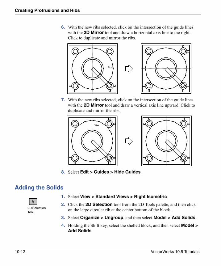
6. With the new ribs selected, click on the intersection of the guide lines with the 2D Mirror tool and draw a horizontal axis line to the right. Click to duplicate and mirror the ribs.
7. With the new ribs selected, click on the intersection of the guide lines with the 2D Mirror tool and draw a vertical axis line upward. Click to duplicate and mirror the ribs.
8. Select Edit > Guides > Hide Guides.
Adding the Solids
1. Select View > Standard Views > Right Isometric.
2. Click the 2D Selection tool from the 2D Tools palette, and then click on the large circular rib at the center bottom of the block.
3. Select Organize > Ungroup, and then select Model > Add Solids.
4. Holding the Shift key, select the shelled block, and then select Model > Add Solids.
2D Selection Tool
10-12 VectorWorks 10.5 Tutorials
Creating Slanted Ribs10
Creating Slanted Ribs
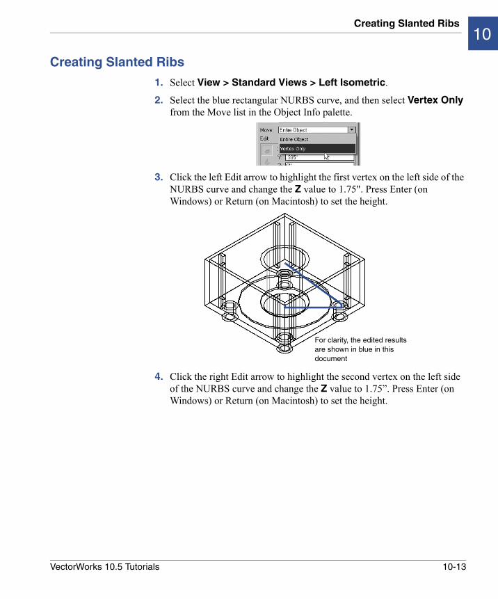
1. Select View > Standard Views > Left Isometric.
2. Select the blue rectangular NURBS curve, and then select Vertex Only from the Move list in the Object Info palette.
3. Click the left Edit arrow to highlight the first vertex on the left side of the NURBS curve and change the Z value to 1.75". Press Enter (on Windows) or Return (on Macintosh) to set the height.
4. Click the right Edit arrow to highlight the second vertex on the left side of the NURBS curve and change the Z value to 1.75”. Press Enter (on Windows) or Return (on Macintosh) to set the height.
For clarity, the edited results are shown in blue in this document
10-13VectorWorks 10.5 Tutorials
Creating Protrusions and Ribs
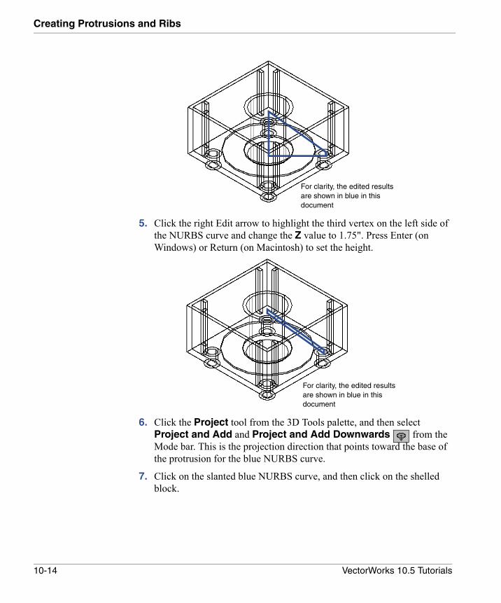
5. Click the right Edit arrow to highlight the third vertex on the left side of the NURBS curve and change the Z value to 1.75". Press Enter (on Windows) or Return (on Macintosh) to set the height.
6. Click the Project tool from the 3D Tools palette, and then select Project and Add and Project and Add Downwards from the Mode bar. This is the projection direction that points toward the base of the protrusion for the blue NURBS curve.
7. Click on the slanted blue NURBS curve, and then click on the shelled block.
For clarity, the edited results are shown in blue in this document
For clarity, the edited results are shown in blue in this document
10-14 VectorWorks 10.5 Tutorials
Mirroring the Slanted Ribs10
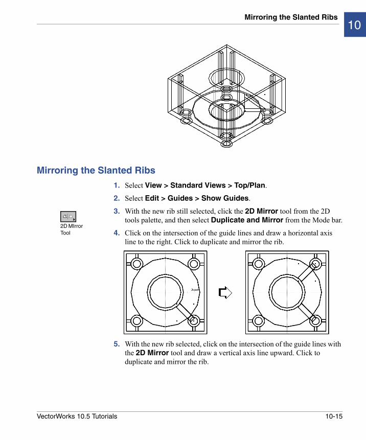
Mirroring the Slanted Ribs
1. Select View > Standard Views > Top/Plan.
2. Select Edit > Guides > Show Guides.
3. With the new rib still selected, click the 2D Mirror tool from the 2D tools palette, and then select Duplicate and Mirror from the Mode bar.
4. Click on the intersection of the guide lines and draw a horizontal axis line to the right. Click to duplicate and mirror the rib.
5. With the new rib selected, click on the intersection of the guide lines with the 2D Mirror tool and draw a vertical axis line upward. Click to duplicate and mirror the rib.
2D MIrror Tool
10-15VectorWorks 10.5 Tutorials
Creating Protrusions and Ribs
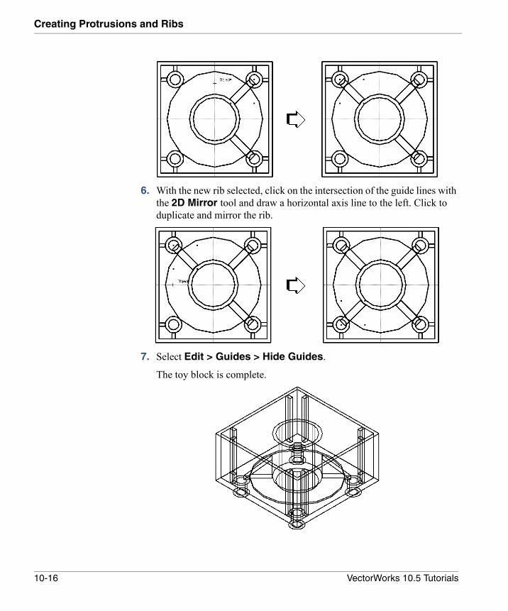
6. With the new rib selected, click on the intersection of the guide lines with the 2D Mirror tool and draw a horizontal axis line to the left. Click to duplicate and mirror the rib.
7. Select Edit > Guides > Hide Guides.
The toy block is complete.
10-16 VectorWorks 10.5 Tutorials
Mirroring the Slanted Ribs10
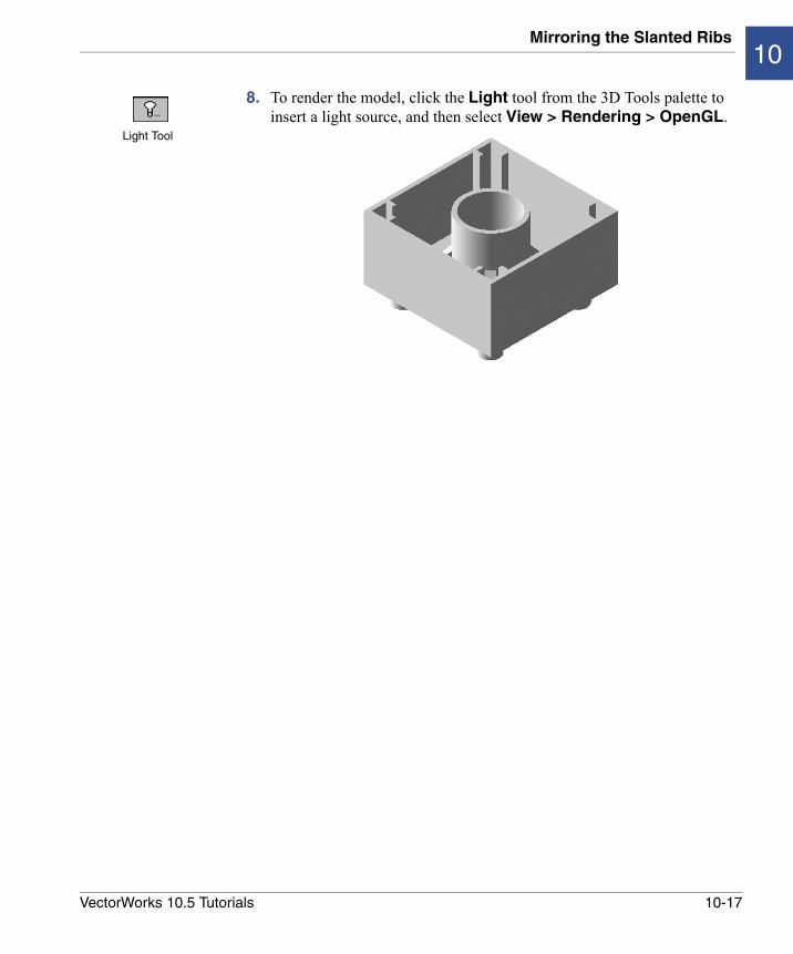
8. To render the model, click the Light tool from the 3D Tools palette to insert a light source, and then select View > Rendering > OpenGL.
Light Tool
10-17VectorWorks 10.5 Tutorials

11
VectorWorks Mechanical Tutorial• Creating a 2D Shaft
• Creating a 3D Shaft from a 2D Shaft
This tutorial, created for Version 10 of VectorWorks, contains procedures for creating a 2D shaft comprised of various shaft segments, a key, and a hole. This 2D shaft is then turned into a 3D object with the Create 3D Object from 2D command.Note: The following procedures list only those parameter
values that must be changed. For all other parameters, leave the default values.
Creating a 2D Shaft
When inserting objects, select the objects either from the Resource Browser or from the appropriate tools palette. Note: An object inserted for the first time from a palette
opens the Object Properties dialog box. Accept the default values and click OK; make changes to the object parameters through the Object Info palette.
1. Select File > New.
The Create Document dialog box opens.
2. Click Use Document Template, and then select VW_Mechanical (Inch).sta from the list. Click OK.
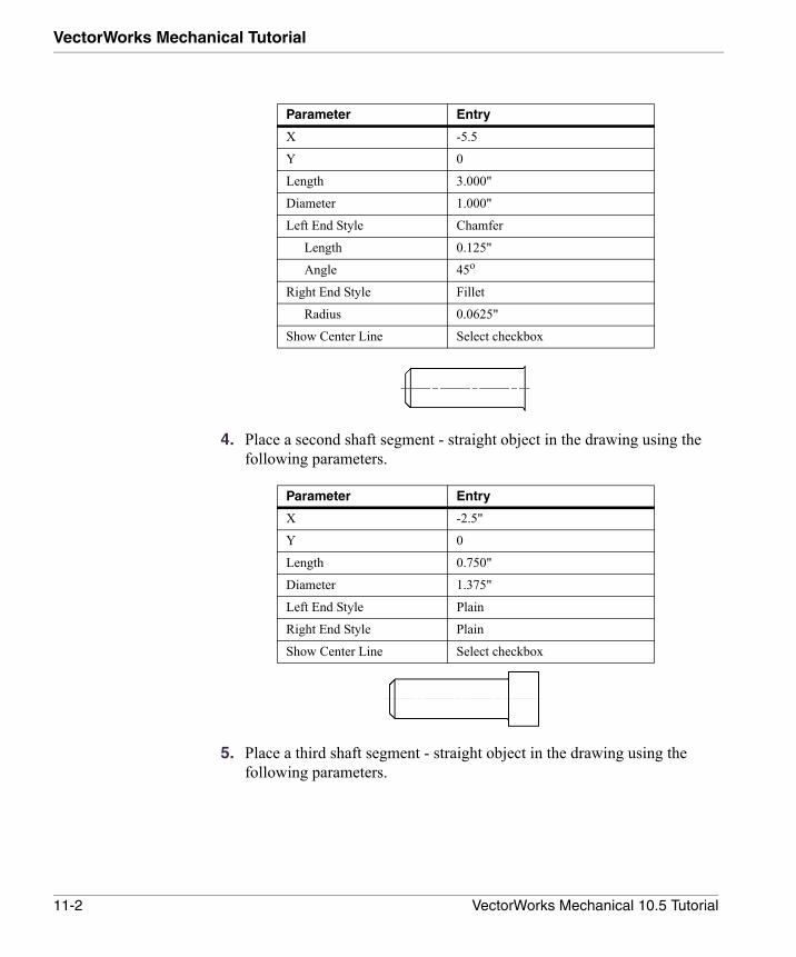
3. Place a shaft segment - straight object in the drawing and enter the following parameters in the Object Info palette.
11-1VectorWorks Mechanical 10.5 Tutorial
VectorWorks Mechanical Tutorial
4. Place a second shaft segment - straight object in the drawing using the following parameters.
5. Place a third shaft segment - straight object in the drawing using the following parameters.
Parameter Entry
X -5.5
Y 0
Length 3.000"
Diameter 1.000"
Left End Style Chamfer
Length 0.125"
Angle 45o
Right End Style Fillet
Radius 0.0625"
Show Center Line Select checkbox
Parameter Entry
X -2.5"
Y 0
Length 0.750"
Diameter 1.375"
Left End Style Plain
Right End Style Plain
Show Center Line Select checkbox
11-2 VectorWorks Mechanical 10.5 Tutorial
Creating a 2D Shaft11
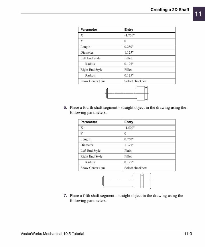
6. Place a fourth shaft segment - straight object in the drawing using the following parameters.
7. Place a fifth shaft segment - straight object in the drawing using the following parameters.
Parameter Entry
X -1.750"
Y 0
Length 0.250"
Diameter 1.125"
Left End Style Fillet
Radius 0.125"
Right End Style Fillet
Radius 0.125"
Show Center Line Select checkbox
Parameter Entry
X -1.500"
Y 0
Length 0.750"
Diameter 1.375"
Left End Style Plain
Right End Style Fillet
Radius 0.125"
Show Center Line Select checkbox
11-3VectorWorks Mechanical 10.5 Tutorial
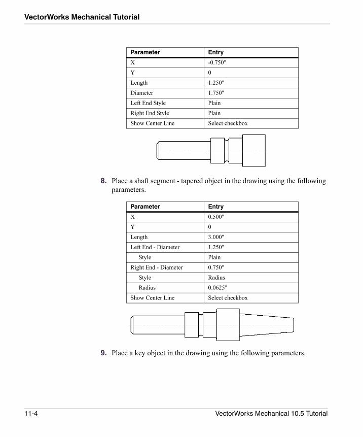
VectorWorks Mechanical Tutorial
8. Place a shaft segment - tapered object in the drawing using the following parameters.
9. Place a key object in the drawing using the following parameters.
Parameter Entry
X -0.750"
Y 0
Length 1.250"
Diameter 1.750"
Left End Style Plain
Right End Style Plain
Show Center Line Select checkbox
Parameter Entry
X 0.500"
Y 0
Length 3.000"
Left End - Diameter 1.250"
Style Plain
Right End - Diameter 0.750"
Style Radius
Radius 0.0625"
Show Center Line Select checkbox
11-4 VectorWorks Mechanical 10.5 Tutorial
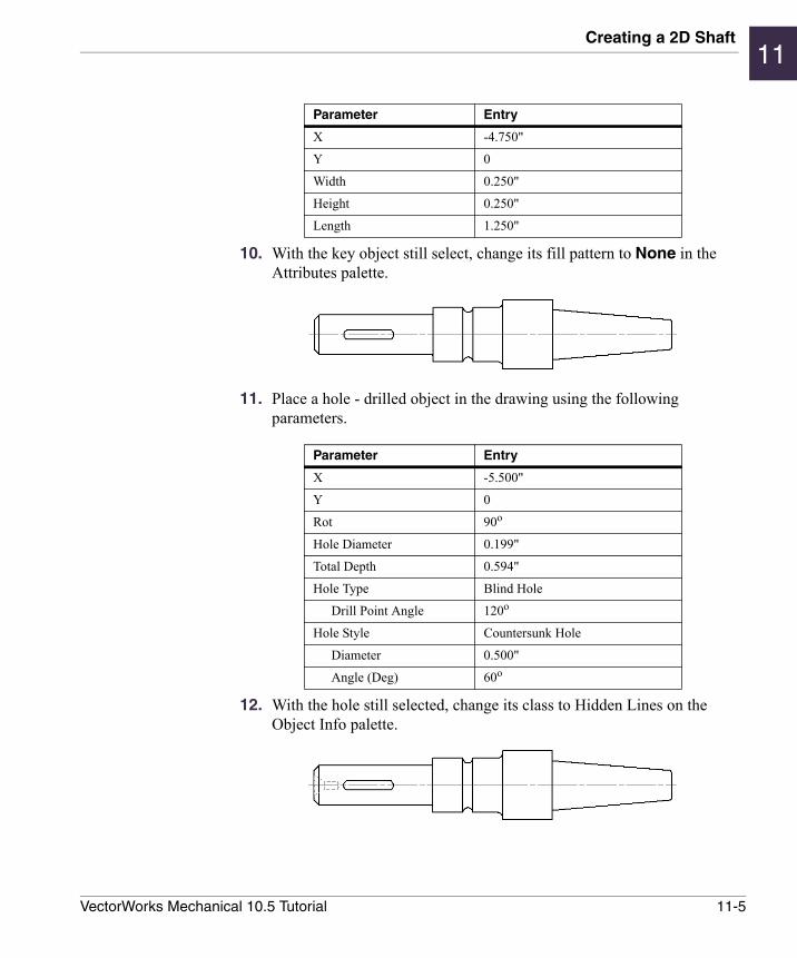
Creating a 2D Shaft11
10. With the key object still select, change its fill pattern to None in the Attributes palette.
11. Place a hole - drilled object in the drawing using the following parameters.
12. With the hole still selected, change its class to Hidden Lines on the Object Info palette.
Parameter Entry
X -4.750"
Y 0
Width 0.250"
Height 0.250"
Length 1.250"
Parameter Entry
X -5.500"
Y 0
Rot 90o
Hole Diameter 0.199"
Total Depth 0.594"
Hole Type Blind Hole
Drill Point Angle 120o
Hole Style Countersunk Hole
Diameter 0.500"
Angle (Deg) 60o
11-5VectorWorks Mechanical 10.5 Tutorial
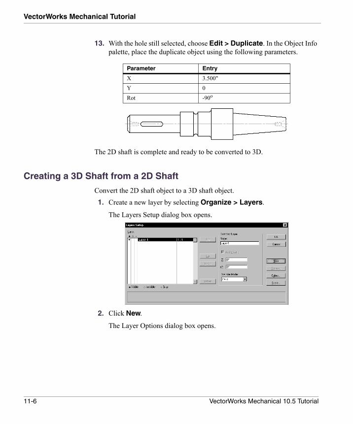
VectorWorks Mechanical Tutorial
13. With the hole still selected, choose Edit > Duplicate. In the Object Info palette, place the duplicate object using the following parameters.
The 2D shaft is complete and ready to be converted to 3D.
Creating a 3D Shaft from a 2D Shaft
Convert the 2D shaft object to a 3D shaft object.1. Create a new layer by selecting Organize > Layers.
The Layers Setup dialog box opens.
2. Click New.
The Layer Options dialog box opens.
Parameter Entry
X 3.500"
Y 0
Rot -90o
11-6 VectorWorks Mechanical 10.5 Tutorial
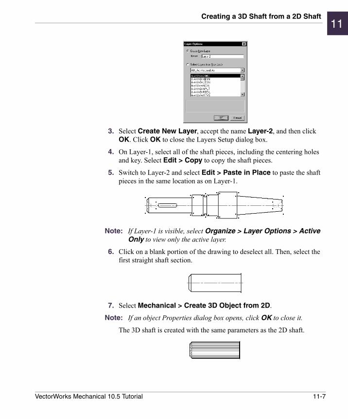
Creating a 3D Shaft from a 2D Shaft11
3. Select Create New Layer, accept the name Layer-2, and then click OK. Click OK to close the Layers Setup dialog box.
4. On Layer-1, select all of the shaft pieces, including the centering holes and key. Select Edit > Copy to copy the shaft pieces.
5. Switch to Layer-2 and select Edit > Paste in Place to paste the shaft pieces in the same location as on Layer-1.
Note: If Layer-1 is visible, select Organize > Layer Options > Active Only to view only the active layer.
6. Click on a blank portion of the drawing to deselect all. Then, select the first straight shaft section.
7. Select Mechanical > Create 3D Object from 2D.
Note: If an object Properties dialog box opens, click OK to close it.
The 3D shaft is created with the same parameters as the 2D shaft.
11-7VectorWorks Mechanical 10.5 Tutorial
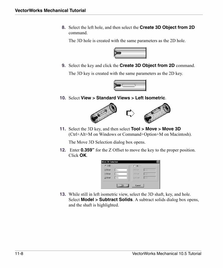
VectorWorks Mechanical Tutorial
8. Select the left hole, and then select the Create 3D Object from 2D command.
The 3D hole is created with the same parameters as the 2D hole.
9. Select the key and click the Create 3D Object from 2D command.
The 3D key is created with the same parameters as the 2D key.
10. Select View > Standard Views > Left Isometric.
11. Select the 3D key, and then select Tool > Move > Move 3D (Ctrl+Alt+M on Windows or Command+Option+M on Macintosh).
The Move 3D Selection dialog box opens.
12. Enter 0.359” for the Z Offset to move the key to the proper position. Click OK.
13. While still in left isometric view, select the 3D shaft, key, and hole. Select Model > Subtract Solids. A subtract solids dialog box opens, and the shaft is highlighted.
11-8 VectorWorks Mechanical 10.5 Tutorial
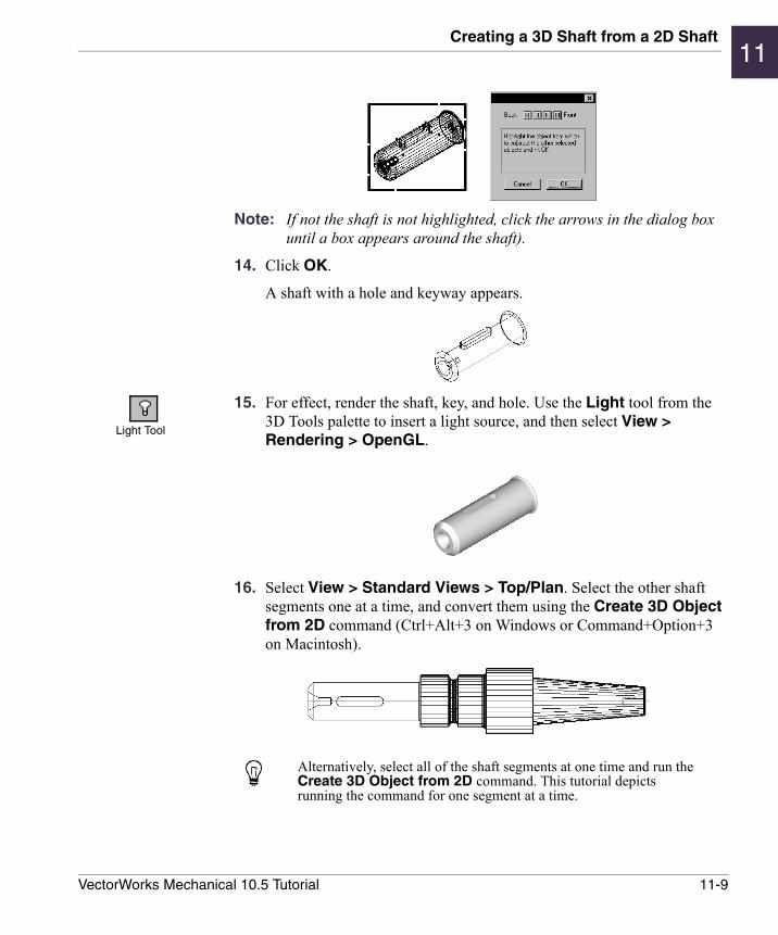
Creating a 3D Shaft from a 2D Shaft11
Note: If not the shaft is not highlighted, click the arrows in the dialog box until a box appears around the shaft).
14. Click OK.
A shaft with a hole and keyway appears.
15. For effect, render the shaft, key, and hole. Use the Light tool from the 3D Tools palette to insert a light source, and then select View > Rendering > OpenGL.
16. Select View > Standard Views > Top/Plan. Select the other shaft segments one at a time, and convert them using the Create 3D Object from 2D command (Ctrl+Alt+3 on Windows or Command+Option+3 on Macintosh).
Alternatively, select all of the shaft segments at one time and run the Create 3D Object from 2D command. This tutorial depicts running the command for one segment at a time.
Light Tool
11-9VectorWorks Mechanical 10.5 Tutorial

VectorWorks Mechanical Tutorial
17. After all shaft segments are converted, select the hole at the end of the tapered shaft and click the Create 3D Object from 2D command.
18. Select the tapered shaft and the hole, and then select Model > Subtract Solids. A box appears around the shaft (if not, click the arrows in the dialog box until a box appears around the shaft). Click OK. A shaft with a hole is created.
19. Select all six shaft segments, and then select Model > Add Solids. Switch to left isometric view and render the shaft using OpenGL, as described previously.
20. To create a more photorealistic shaft, apply a texture (such as stainless steel) to the shaft and render it using View > Rendering > Final Quality RenderWorks (RenderWorks required).
11-10 VectorWorks Mechanical 10.5 Tutorial
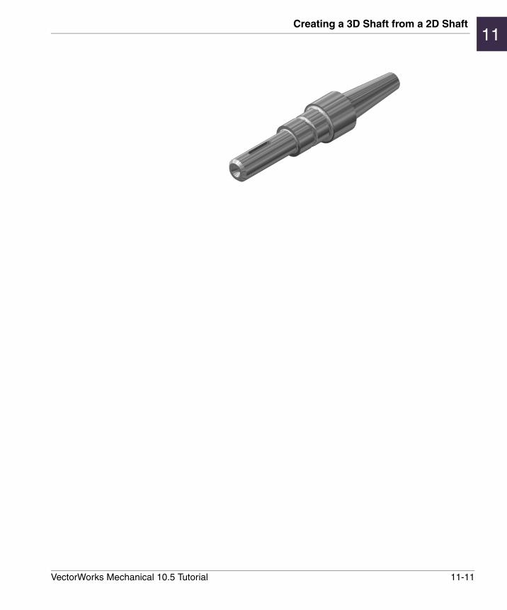
Creating a 3D Shaft from a 2D Shaft11
11-11VectorWorks Mechanical 10.5 Tutorial