
Multi Body Simulation of a Valve Train, Comparison of 1D and 3D Models and Measurement
When building performance engines, weoften ask a production engine to go wellbeyond where it was intended to go, bothin output and in RPM. Since we did notdesign the engine, we are limited toselecting improved components andotherwise doing the best we can withwhat we have.
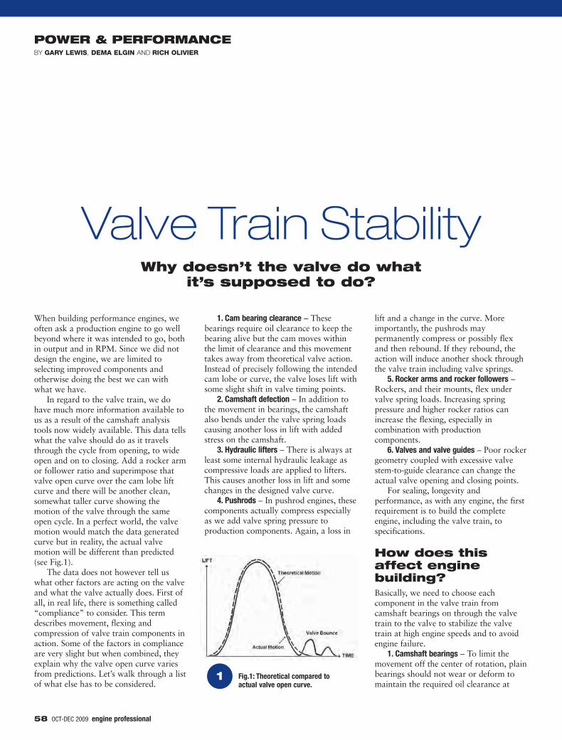
In regard to the valve train, we dohave much more information available tous as a result of the camshaft analysistools now widely available. This data tellswhat the valve should do as it travelsthrough the cycle from opening, to wideopen and on to closing. Add a rocker armor follower ratio and superimpose thatvalve open curve over the cam lobe liftcurve and there will be another clean,somewhat taller curve showing themotion of the valve through the sameopen cycle. In a perfect world, the valvemotion would match the data generatedcurve but in reality, the actual valvemotion will be different than predicted(see Fig.1).
The data does not however tell uswhat other factors are acting on the valveand what the valve actually does. First ofall, in real life, there is something called“compliance” to consider. This termdescribes movement, flexing andcompression of valve train components inaction. Some of the factors in complianceare very slight but when combined, theyexplain why the valve open curve variesfrom predictions. Let’s walk through a listof what else has to be considered.
1. Cam bearing clearance – Thesebearings require oil clearance to keep thebearing alive but the cam moves withinthe limit of clearance and this movementtakes away from theoretical valve action.Instead of precisely following the intendedcam lobe or curve, the valve loses lift withsome slight shift in valve timing points.
2. Camshaft defection – In addition tothe movement in bearings, the camshaftalso bends under the valve spring loadscausing another loss in lift with addedstress on the camshaft.
3. Hydraulic lifters – There is always atleast some internal hydraulic leakage ascompressive loads are applied to lifters.This causes another loss in lift and somechanges in the designed valve curve.
4. Pushrods – In pushrod engines, thesecomponents actually compress especiallyas we add valve spring pressure toproduction components. Again, a loss in
lift and a change in the curve. Moreimportantly, the pushrods maypermanently compress or possibly flexand then rebound. If they rebound, theaction will induce another shock throughthe valve train including valve springs.
5. Rocker arms and rocker followers –Rockers, and their mounts, flex undervalve spring loads. Increasing springpressure and higher rocker ratios canincrease the flexing, especially incombination with productioncomponents.
6. Valves and valve guides – Poor rockergeometry coupled with excessive valvestem-to-guide clearance can change theactual valve opening and closing points.
For sealing, longevity andperformance, as with any engine, the firstrequirement is to build the completeengine, including the valve train, tospecifications.
How does thisaffect enginebuilding?Basically, we need to choose eachcomponent in the valve train fromcamshaft bearings on through the valvetrain to the valve to stabilize the valvetrain at high engine speeds and to avoidengine failure.
1. Camshaft bearings – To limit themovement off the center of rotation, plainbearings should not wear or deform tomaintain the required oil clearance at
58 OCT-DEC 2009
Valve Train StabilityWhy doesn’t the valve do what
it’s supposed to do?
POWER & PERFORMANCEGARY LEWIS DEMA ELGIN RICH OLIVIER
1
OCT-DEC 2009 59
continuous high engine speeds. Rollerbearings with minimum clearances aresometimes retrofitted.
2. Camshafts – If we had the option,we would probably choose camshaftswith more and larger bearing journals sothat we could have tall cam lobes and alarge core diameter. However, we are notdesigning the engine but instead limited tomaking the best of what we have.Stiffness can be maintained by avoidinggrinding cam lobe base circles too farundersize to maintain the existing corediameter. Also, valve spring pressuresshould be adequate to control valveaction but not so excessive as to exertunnecessary loads on the camshaft.
3. Cam lobe profiles – The valve actiongenerated by the cam lobe should ideallybe smooth and not allow shocks to thevalve train on opening or closing orlaunch the valve over the nose. Shocks tothe system not only stress individualcomponents but also release energy intovalve springs that can cause them to surgeor oscillate.
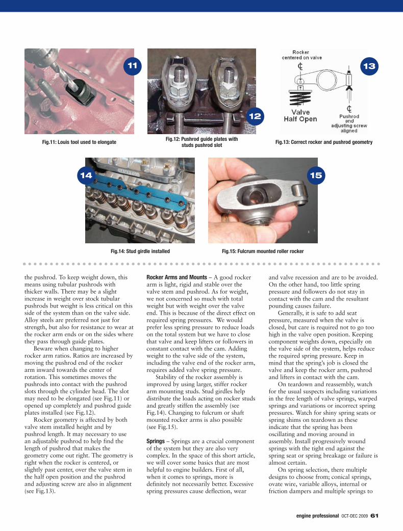
4. Lifters or followers – With flattappets, lifter bores should be square withthe camshaft centerline and offset to oneside of the cam lobe to promote rotation.Roller tappets should also align squarelywith the camshaft centerline so that theroller does not contact on one edge.Alignments need to be checked andblueprinting may be required to avoidearly failure.
5. Pushrods – Pushrods should be stiffbut also light. This typically meanstubular construction with alloy materialsand thick walls.
6. Rocker arms and mounts – Rockerarms should also be stiff and light inweight especially at the valve end. Addingweight at the valve end, along with theweight of valves and spring retainers,adds to required spring pressures and tostresses on all valve train components.Rocker studs or capscrews can bereplaced with larger diameter or stifferpieces. Rockers may also be shaft(fulcrum) mounted for greater stability.
7. Valves – Valves are selected for size,weight and flow characteristics. Forstability, lighter valves means that we cancontrol the valve action with less springpressure.
8. Springs and retainers – There arenumerous variations in spring designincluding multiple springs, differentalloys, round or ovate wire, andprogressively wound springs or conical
springs. Aside from providing therequired pressures, springs must remainstable at high engine speeds without thesurging or oscillating that causes a loss ofvalve control. Spring design is absolutelycritical and must be carefully matched tothe total valve train and RPM range ofthe engine.
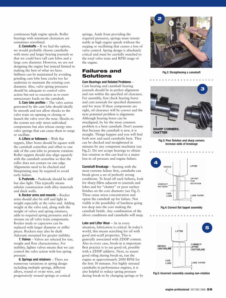
Failures andSolutionsCam Bearings and Related Problems –Cam bearing and camshaft bearingjournals should be in perfect alignmentand run within the specified oil clearance.For assembly, first check bearing boresand cam journals for specified diametersand for wear. If these components areright, oil clearance will be correct and thenext potential problem is alignment.Although bearing bores can bemisaligned, by far the most commonproblem is a bent camshaft. Don’t assumethat because the camshaft is new, it isstraight. Things happen and you will findboth new and used camshafts bent. Theycan be checked and straightened inminutes by any competent machinist (seeFig.2). Do not scrape bearings to obtainfree rotation as this can lead to a majorloss in oil pressure and engine failure.
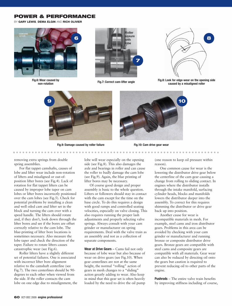
Camshaft Breakage – Starting with themost extreme failure first, camshafts canbreak given a set of perfectly wrongconditions. To head off such failures, lookfor sharp fillets adjacent to journals andlobes and for “chatter” or poor surfacefinishes on the core diameter (see Fig.3).These cause stress concentration andopens the camshaft up for failure. Notvisible is the possibility of hardness goingtoo deep into the core making thecamshaft brittle. Any combination of theabove conditions and camshafts will snap.
Lobe and Lifter Wear – As in everysituation, lubrication is critical. In today’sworld, this means searching for oil withgood anti-scuff properties. This isgenerally associated with ZDDP content.Also in every case, break-in is important.Best practice is to use good oil, possiblywith a ZDDP additive. Next, to assuregood oiling during break-in, run theengine at approximately 2000 RPM forthe first 30 minutes. For highly stressedcamshafts in performance engines, it isalso helpful to reduce spring pressureduring break-in by changing springs or by
5
4
3
2
60 OCT-DEC 2009
POWER & PERFORMANCEGARY LEWIS DEMA ELGIN RICH OLIVIER
removing extra springs from doublespring assemblies.
For flat tappet camshafts, causes oflobe and lifter wear include non-rotationof lifters and misaligned or out-of-position lifter bores (see Fig.4). Lack ofrotation for flat tappet lifters can becaused by improper lobe taper on camlobes or lifter bores incorrectly positionedover the cam lobes (see Fig.5). Check forpotential problems by installing a cleanand well oiled cam and lifter set in theblock and turning the cam over with aspeed handle. The lifters should rotateand, if they don’t, look down through thelifter bores and see if the bores are offsetcorrectly relative to the cam lobe. Theblue-printing of lifter bore locations issometimes necessary. Also measure thelobe taper and check the direction of thetaper. Failure to rotate lifters causescatastrophic wear (see Fig.6).
Roller lifters have a slightly differentset of potential failures. One is associatedwith incorrect lifter bore alignmentrelative to the camshaft centerline (seeFig.7). The two centerlines should be 90-degrees to each other when viewed fromthe side. If the roller contacts the camlobe on one edge due to misalignment, the
lobe will wear especially on the openingside (see Fig.8). This also damages theaxle and bearings in roller and can causethe roller to badly damage the cam lobe(see Fig.9). Again, the blue printing oflifter bores may be necessary.
Of course good design and properassembly is basic to the whole question.Lifters or followers should stay in contactwith the cam except for the time on thebase circle. To do this requires a designwith good ramps and controlled seatingvelocities, especially on valve closing. Thisalso requires running the proper lashadjustments and properly selecting valvesprings. Always consult with your camgrinder or manufacturer on springrequirements. Deal with the valve train asan assembly and not as a collection ofseparate components.
Wear at Drive Gears – Cams fail not onlybecause of lobe wear but also because ofwear on drive gears (see Fig.10). Whengear centerlines are not at the sameheight, the normal “rolling” action ofgears in mesh changes to a “sliding”action greatly adding to wear. Also keepin mind that this gear set is often heavilyloaded by the need to drive the oil pump
(one reason to keep oil pressure withinreason).
One common cause for wear is thelowering the distributor drive gear belowthe centerline of the cam gear causing achange from rolling to sliding contact. Inengines where the distributor installsthrough the intake manifold, surfacingcylinder heads, blocks and manifoldslowers the distributor deeper into theassembly. To correct for this requiresshimming the distributor or drive gearback up into position.
Another cause for wear isincompatible materials in mesh. Forexample, steel cams and iron distributorgears. Problems in this area can beavoided by checking with your camgrinder or manufacturer and runningbronze or composite distributor drivegears. Bronze gears are compatible withsteel cams and composite gears arecompatible with all materials. Gear wearcan also be reduced by directing oil ontothe gears but caution is required toprevent reducing oil to other parts of theengine.
Pushrods – The entire valve train benefitsby improving stiffness including of course,
6
7
9
10
8
OCT-DEC 2009 61
the pushrod. To keep weight down, thismeans using tubular pushrods withthicker walls. There may be a slightincrease in weight over stock tubularpushrods but weight is less critical on thisside of the system than on the valve side.Alloy steels are preferred not just forstrength, but also for resistance to wear atthe rocker arm ends or on the sides wherethey pass through guide plates.
Beware when changing to higherrocker arm ratios. Ratios are increased bymoving the pushrod end of the rockerarm inward towards the center ofrotation. This sometimes moves thepushrods into contact with the pushrodslots through the cylinder head. The slotmay need to be elongated (see Fig.11) oropened up completely and pushrod guideplates installed (see Fig.12).
Rocker geometry is affected by bothvalve stem installed height and bypushrod length. It may necessary to usean adjustable pushrod to help find thelength of pushrod that makes thegeometry come out right. The geometry isright when the rocker is centered, orslightly past center, over the valve stem inthe half open position and the pushrodand adjusting screw are also in alignment(see Fig.13).
Rocker Arms and Mounts – A good rockerarm is light, rigid and stable over thevalve stem and pushrod. As for weight,we not concerned so much with totalweight but with weight over the valveend. This is because of the direct effect onrequired spring pressures. We wouldprefer less spring pressure to reduce loadson the total system but we have to closethat valve and keep lifters or followers inconstant contact with the cam. Addingweight to the valve side of the system,including the valve end of the rocker arm,requires added valve spring pressure.
Stability of the rocker assembly isimproved by using larger, stiffer rockerarm mounting studs. Stud girdles helpdistribute the loads acting on rocker studsand greatly stiffen the assembly (seeFig.14). Changing to fulcrum or shaftmounted rocker arms is also possible (see Fig.15).
Springs – Springs are a crucial componentof the system but they are also verycomplex. In the space of this short article,we will cover some basics that are mosthelpful to engine builders. First of all,when it comes to springs, more isdefinitely not necessarily better. Excessivespring pressures cause deflection, wear
and valve recession and are to be avoided.On the other hand, too little springpressure and followers do not stay incontact with the cam and the resultantpounding causes failure.
Generally, it is safe to add seatpressure, measured when the valve isclosed, but care is required not to go toohigh in the valve open position. Keepingcomponent weights down, especially onthe valve side of the system, helps reducethe required spring pressure. Keep inmind that the spring’s job is closed thevalve and keep the rocker arm, pushrodand lifters in contact with the cam.
On teardown and reassembly, watchfor the usual suspects including variationsin the free length of valve springs, warpedsprings and variations or incorrect springpressures. Watch for shiny spring seats orspring shims on teardown as theseindicate that the spring has beenoscillating and moving around inassembly. Install progressively woundsprings with the tight end against thespring seat or spring breakage or failure isalmost certain.
On spring selection, there multipledesigns to choose from; conical springs,ovate wire, variable alloys, internal orfriction dampers and multiple springs to
11
12
14
15
13
POWER & PERFORMANCEGARY LEWIS DEMA ELGIN RICH OLIVIER
name a few. At the design level, valvetrain weights, stiffness, RPM levels andrequired longevity are all considered.What does all this mean to us? If we buya cam kit including springs, be sure thatthe kit is selected exactly for the intendeduse. Otherwise, consult with the camgrinder or manufacturer for specificspring recommendations. Failure to dothis could cost you an engine.
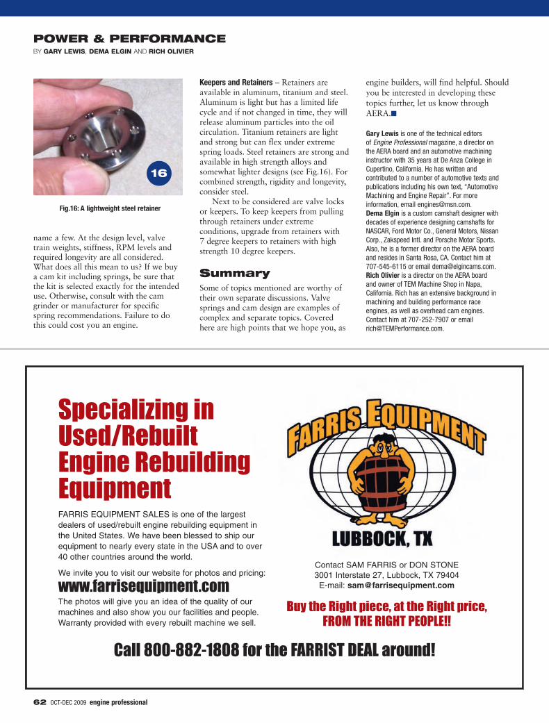
Keepers and Retainers – Retainers areavailable in aluminum, titanium and steel.Aluminum is light but has a limited lifecycle and if not changed in time, they willrelease aluminum particles into the oilcirculation. Titanium retainers are lightand strong but can flex under extremespring loads. Steel retainers are strong andavailable in high strength alloys andsomewhat lighter designs (see Fig.16). Forcombined strength, rigidity and longevity,consider steel.
Next to be considered are valve locksor keepers. To keep keepers from pullingthrough retainers under extremeconditions, upgrade from retainers with 7 degree keepers to retainers with highstrength 10 degree keepers.
SummarySome of topics mentioned are worthy oftheir own separate discussions. Valvesprings and cam design are examples ofcomplex and separate topics. Coveredhere are high points that we hope you, as
engine builders, will find helpful. Shouldyou be interested in developing thesetopics further, let us know throughAERA.�
Gary Lewis is one of the technical editors of Engine Professional magazine, a director onthe AERA board and an automotive machininginstructor with 35 years at De Anza College inCupertino, California. He has written andcontributed to a number of automotive texts andpublications including his own text, “AutomotiveMachining and Engine Repair”. For moreinformation, email [email protected]. Dema Elgin is a custom camshaft designer withdecades of experience designing camshafts forNASCAR, Ford Motor Co., General Motors, NissanCorp., Zakspeed Intl. and Porsche Motor Sports.Also, he is a former director on the AERA boardand resides in Santa Rosa, CA. Contact him at707-545-6115 or email [email protected] Olivier is a director on the AERA boardand owner of TEM Machine Shop in Napa,California. Rich has an extensive background inmachining and building performance raceengines, as well as overhead cam engines.Contact him at 707-252-7907 or [email protected].
Specializing in Used/RebuiltEngine Rebuilding EquipmentFARRIS EQUIPMENT SALES is one of the largestdealers of used/rebuilt engine rebuilding equipment inthe United States. We have been blessed to ship ourequipment to nearly every state in the USA and to over40 other countries around the world.
We invite you to visit our website for photos and pricing:
www.farrisequipment.comThe photos will give you an idea of the quality of ourmachines and also show you our facilities and people. Warranty provided with every rebuilt machine we sell.
Contact SAM FARRIS or DON STONE3001 Interstate 27, Lubbock, TX 79404
E-mail: [email protected]
Buy the Right piece, at the Right price, FROM THE RIGHT PEOPLE!!
Call 800-882-1808 for the FARRIST DEAL around!
62 OCT-DEC 2009
16


