C H A P T E R 18 Camshaft and Valve Train Service.
42
-
Upload
katherine-harmon -
Category
Documents
-
view
260 -
download
2
Transcript of C H A P T E R 18 Camshaft and Valve Train Service.

C H A P T E R 18
Camshaft and
Valve Train Service

Permission granted to reproduce for educational use only.© Goodheart-Willcox Co., Inc.
• Explain how to inspect and service the camshaft.• Summarize service procedures for in-block and
overhead valve assemblies.• Describe the steps in inspecting and reconditioning
valve seats.• Explain how to inspect and recondition valve lifters
and valve guides.
Learning Objectives

Permission granted to reproduce for educational use only.© Goodheart-Willcox Co., Inc.
Introduction to Valve Train Service
• Valve train performs several vital functions– Allows air-fuel mixture into cylinder– Seals combustion chamber during compression– Allows exhaust gases to exit cylinder
• Damaged parts must be reconditioned or replaced– Also, parts in contact with damaged parts

Permission granted to reproduce for educational use only.© Goodheart-Willcox Co., Inc.
Camshaft Service
• Inspect camshaft for wear or damage– Bearing surfaces, lobes, timing gear– Timing gears need to be replaced in pairs
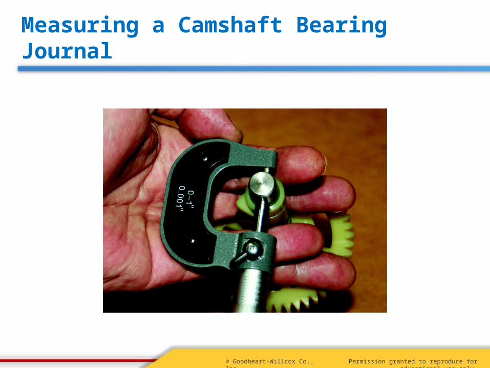
• Measure journals and lobes for wear– Measure bearing bores in crankcase and cover
• Check compression release mechanism for proper operation
Permission granted to reproduce for educational use only.© Goodheart-Willcox Co., Inc.
Measuring a Camshaft Bearing Journal

Permission granted to reproduce for educational use only.© Goodheart-Willcox Co., Inc.
Measuring a Camshaft Bearing Bore

Permission granted to reproduce for educational use only.© Goodheart-Willcox Co., Inc.
Measuring a Camshaft Lobe
Permission granted to reproduce for educational use only.© Goodheart-Willcox Co., Inc.
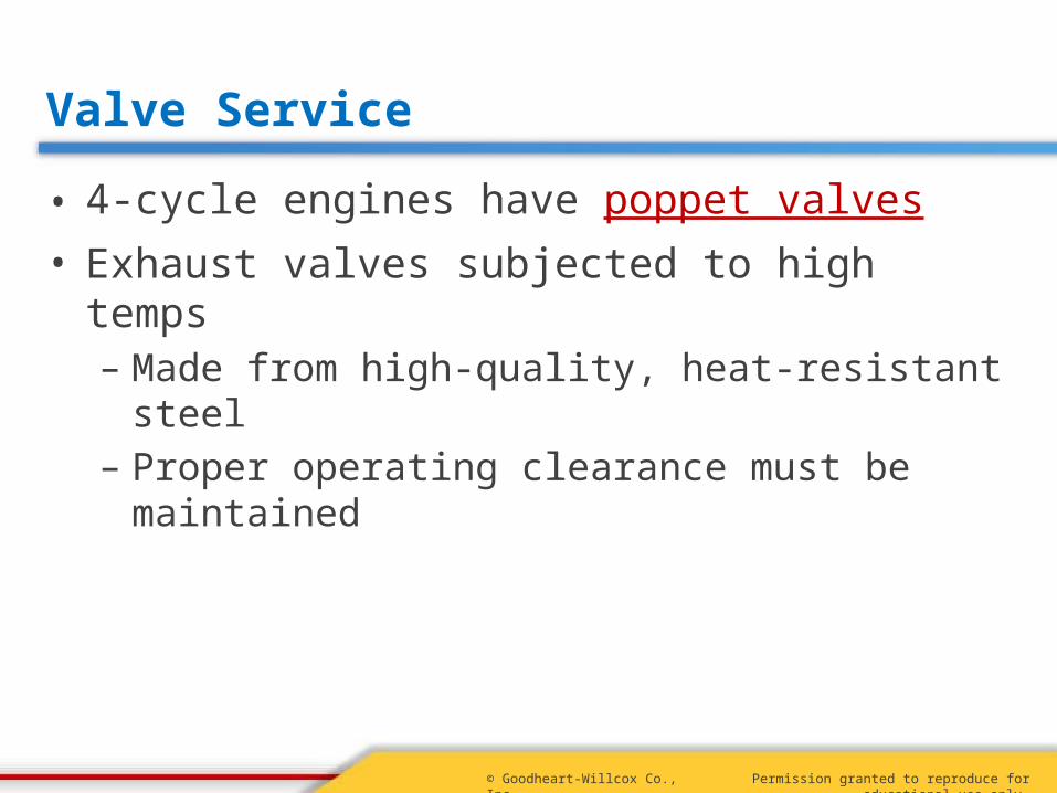
Valve Service
• 4-cycle engines have poppet valves• Exhaust valves subjected to high temps
– Made from high-quality, heat-resistant steel– Proper operating clearance must be maintained

Permission granted to reproduce for educational use only.© Goodheart-Willcox Co., Inc.
Inspecting Valves and Seats
• Clean valves with power wire brush• Inspect valves
– Damaged faces, heads, or stems– Warped valve head– Worn, improperly ground, or bent stems– Thin margins or partial seating
• Replace or refinish damaged valves
Permission granted to reproduce for educational use only.© Goodheart-Willcox Co., Inc.
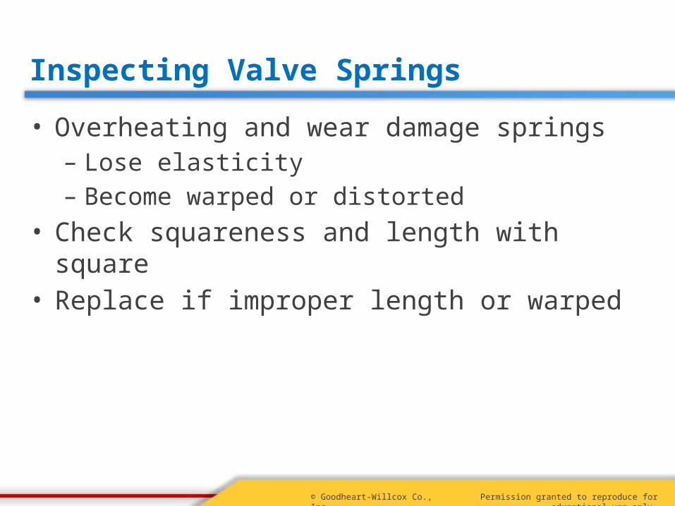
Inspecting Valve Springs
• Overheating and wear damage springs– Lose elasticity– Become warped or distorted
• Check squareness and length with square• Replace if improper length or warped

Permission granted to reproduce for educational use only.© Goodheart-Willcox Co., Inc.
Valve Guides
• Align valves with valve seats• Clearance must be correct
– Allows for heat expansion and lubrication– Valve tipping causes improper seating– Proper clearance is typically .002 to .003
• Replaceable valve guide inserts• Integral valve guides

Permission granted to reproduce for educational use only.© Goodheart-Willcox Co., Inc.
Types of Valve Guides

Permission granted to reproduce for educational use only.© Goodheart-Willcox Co., Inc.
Inspecting Valve Guides
• Must be cleaned before inspection– Cylindrical wire brush
• Determining clearance– Measure valve guide with small hole gauge– Measure valve stem with micrometer– Guide diameter minus valve stem diameter
• Some guides measured with plug gauge

Permission granted to reproduce for educational use only.© Goodheart-Willcox Co., Inc.
Correcting Worn Integral Valve Guides
• Ream guide and install replacement valve– Valves with oversize stems must be available
• Ream valve and install thin-walled bushing– Bushing must be reamed with finish reamer– Wash all chips away with penetrating oil

Permission granted to reproduce for educational use only.© Goodheart-Willcox Co., Inc.
Valve Guide Bushing Replacement
• Refer to manufacturer’s service manual• Depth of guide is measured• Iron guides driven out through the bottom• Brass guides pulled out through top• Replacement guide pressed into bore
– Same depth as old bushing

Permission granted to reproduce for educational use only.© Goodheart-Willcox Co., Inc.
Pulling a Soft Metal Valve Guide
(Briggs & Stratton Corp.)
Permission granted to reproduce for educational use only.© Goodheart-Willcox Co., Inc.
Refacing Valves
• Can be ground with abrasive stone• Can be cut on special lathe• Can be cut with manual cutter• Cut to 30 or 45

Permission granted to reproduce for educational use only.© Goodheart-Willcox Co., Inc.
Valve Cutting Lathe
(Neway Mfg. Co.)

Permission granted to reproduce for educational use only.© Goodheart-Willcox Co., Inc.
Manual Valve Refacer
(Neway Mfg. Co.)
Permission granted to reproduce for educational use only.© Goodheart-Willcox Co., Inc.
Valve Lifter Service
• Inspect valve lifter contact surface– Concavity, scoring, deformities
• Insert lifter in guide and check for play– Should move freely in guide– Lifter should not wiggle in its guide– Side play can be measured with a dial indicator
Permission granted to reproduce for educational use only.© Goodheart-Willcox Co., Inc.
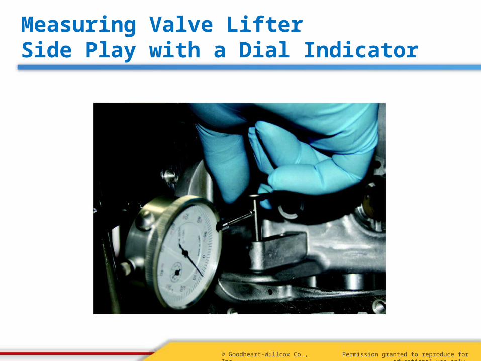
Measuring Valve Lifter Side Play with a Dial Indicator
Permission granted to reproduce for educational use only.© Goodheart-Willcox Co., Inc.
Valve Seat Service
• Should always be reconditioned or replaced• Inspect seat for looseness or damage• Some seats are replaceable• Some seats are an integral part of block
– Must be bored out and seat insert installed– May be more practical to replace block

Permission granted to reproduce for educational use only.© Goodheart-Willcox Co., Inc.
Peening a Valve Seat Insert
• Peening secures loose seat• Place insert squarely in its bore• Seat insert using centerpunch and hammer
– Three points equidistant around rim
• Use drift punch to indent block material outside insert’s rim– Work around rim in a star pattern

Permission granted to reproduce for educational use only.© Goodheart-Willcox Co., Inc.
Peening a Valve Seat Insert
(Briggs & Stratton Corp.)

Permission granted to reproduce for educational use only.© Goodheart-Willcox Co., Inc.
Valve Seat Angle and Width
• Valve seats generally cut to 45 or 30– Some seats cut with 1 interference angle
• Valve seat width must be correct– Wide enough to prevent cutting into valve face– Enough contact surface for heat dissipation– Not so wide as to cause carbon buildup– Typically .030 to .060
Permission granted to reproduce for educational use only.© Goodheart-Willcox Co., Inc.
Refacing (Cutting) Valve Seats
• Special cutting tool with carbide blades• Seat condition determines amount of cutting• Cover seat area in ink before cutting
– Makes progress easier to see
Permission granted to reproduce for educational use only.© Goodheart-Willcox Co., Inc.
Refacing (Cutting) Valve Seats
• Place pilot in valve guide• Slide cutter over pilot• Install T-handle and use it to turn cutter
– Moderate downward pressure– Clockwise direction only
• Remove cutter and check progress• After cutting seat, wash away chips

Permission granted to reproduce for educational use only.© Goodheart-Willcox Co., Inc.
Valve Seat Cutters
(Neway Mfg. Co.)

Permission granted to reproduce for educational use only.© Goodheart-Willcox Co., Inc.
Replacing Valve Seat Inserts
• Damaged seat inserts pulled– Use special puller, slide hammer, or pry bar
• Replacement insert is installed– Chamfered edge down– Peened in place
• Some integral seats replaced with insert• Reface newly installed seat inserts

Permission granted to reproduce for educational use only.© Goodheart-Willcox Co., Inc.
Driving In a Valve Seat Insert
(Briggs & Stratton Corp.)
Permission granted to reproduce for educational use only.© Goodheart-Willcox Co., Inc.
Lapping Valves
• Lapping compound is grease and abrasives– Course and fine grades
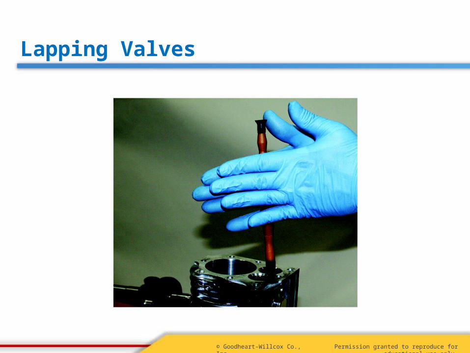
• Procedure:– Apply lapping compound to valve face– Attach lapping stick to valve head– Place valve in guide and twirl– Finished when gray band appears on valve face
• Clean valve and block after lapping
Permission granted to reproduce for educational use only.© Goodheart-Willcox Co., Inc.
Lapping Valves

Permission granted to reproduce for educational use only.© Goodheart-Willcox Co., Inc.
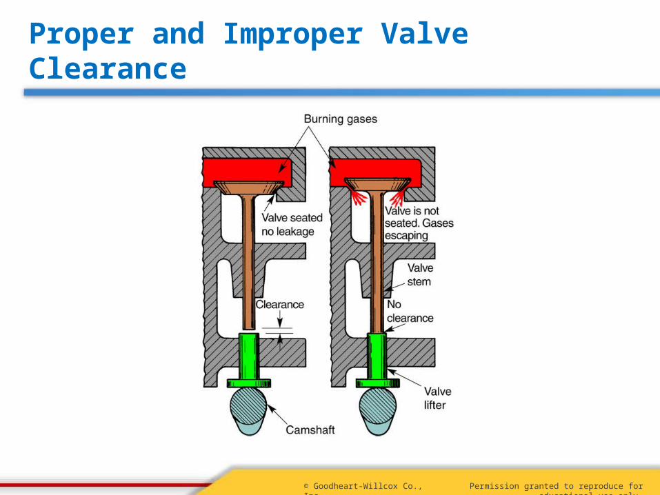
Valve Lifter-to-Stem Clearance
• Space between lifter and end of valve stem– Exhaust valve typically has greater clearance
• Too little clearance– May keep valve open, burning valve and seat– Advances valve timing
• Too much clearance– Reduces valve lift– Rapid lifter wear
Permission granted to reproduce for educational use only.© Goodheart-Willcox Co., Inc.
Proper and Improper Valve Clearance

Permission granted to reproduce for educational use only.© Goodheart-Willcox Co., Inc.
Adjusting Valve Lifter-to-Stem Clearance
• Valve refacing reduces clearance• Measuring clearance
– Insert valve in guide– Rotate camshaft so lobe is opposite stem– Hold valve against seat– Slide feeler gauge between lifter and stem
• Adjust lifter or grind end of valve stem

Permission granted to reproduce for educational use only.© Goodheart-Willcox Co., Inc.
Measuring Valve Clearance
Permission granted to reproduce for educational use only.© Goodheart-Willcox Co., Inc.
Servicing Overhead Valves, Seats, and Guides
• Serviced in same way as on L-head engines• Valves cleaned and resurfaced• Seats reconditioned• Measure and recondition guides as needed

Permission granted to reproduce for educational use only.© Goodheart-Willcox Co., Inc.
Review
What parts are measured to check a camshaft for wear?
The camshaft’s bearing journals, the camshaft bearing bores in the crankcase and cover, and the camshaft lobes.

Permission granted to reproduce for educational use only.© Goodheart-Willcox Co., Inc.
Review
What are the two most common angles for valve faces?
45 and 30
Permission granted to reproduce for educational use only.© Goodheart-Willcox Co., Inc.
Review
How are valve seat inserts secured in their bores?
Peening

Permission granted to reproduce for educational use only.© Goodheart-Willcox Co., Inc.
Review
What problems are associated with insufficient valve lifter-to-stem clearance?
Advanced valve timing, improper valve seating, burned valves and seats


![l THE UNDISPUTED LEADER - Shaw Toyota PuneValve Train Double Overhead Camshaft [DOHC], 16-ValveD ouble Overhead Camshaft [DOHC], Dual VVTi, 16-Valve Charging System Variable Nozzle](https://static.fdocuments.us/doc/165x107/611fb362605c0b3b031b1f31/l-the-undisputed-leader-shaw-toyota-pune-valve-train-double-overhead-camshaft.jpg)