OBSERVATIONS ON PETROLEUM PRODUCT SUPPLY - National Petroleum Council

Revision -, October 2003 Rev A, December 2004
HT-TongUser's Manual
HT-TongUser's Manual
pn 50006190

© Copyright 2004 Varco LP. All rights reserved.
Varco is a registered trademark of Varco I/P reg. U.S. Patent & Trademark Office. This publication is the property of, and contains information proprietary to Varco International, Inc. No part of this publication may be reproduced or copied in any form, or by any means, including electronic, mechanical, photocopying, recording or otherwise, without the prior written permission of Varco IP®.
All product, brand, or trade names used in this publication are the trademarks or registered trademarks of their respective owners. Information in this manual is subject to change without notice.

Table of Contents
Chapter 1: General informationHow to use this manual . . . . . . . . . . . . . . . . . . . . . . . . . . . . . . . . . . . . . . . . . . . . . . . . . . . . . . . . 1-5
Special information . . . . . . . . . . . . . . . . . . . . . . . . . . . . . . . . . . . . . . . . . . . . . . . . . . . . . . . . 1-5Intended audience . . . . . . . . . . . . . . . . . . . . . . . . . . . . . . . . . . . . . . . . . . . . . . . . . . . . . . . . 1-5
Conventions . . . . . . . . . . . . . . . . . . . . . . . . . . . . . . . . . . . . . . . . . . . . . . . . . . . . . . . . . . . . . . . . 1-5Notes, Cautions, and Warnings . . . . . . . . . . . . . . . . . . . . . . . . . . . . . . . . . . . . . . . . . . . . . . 1-5Note: . . . . . . . . . . . . . . . . . . . . . . . . . . . . . . . . . . . . . . . . . . . . . . . . . . . . . . . . . . . . . . . . . . . 1-6Caution: . . . . . . . . . . . . . . . . . . . . . . . . . . . . . . . . . . . . . . . . . . . . . . . . . . . . . . . . . . . . . . . . . 1-6Warning: . . . . . . . . . . . . . . . . . . . . . . . . . . . . . . . . . . . . . . . . . . . . . . . . . . . . . . . . . . . . . . . . 1-6
Illustrations . . . . . . . . . . . . . . . . . . . . . . . . . . . . . . . . . . . . . . . . . . . . . . . . . . . . . . . . . . . . . . . . . 1-6Safety Requirements . . . . . . . . . . . . . . . . . . . . . . . . . . . . . . . . . . . . . . . . . . . . . . . . . . . . . . . . . 1-6General System Safety Practices . . . . . . . . . . . . . . . . . . . . . . . . . . . . . . . . . . . . . . . . . . . . . . . . 1-7
Personnel Training . . . . . . . . . . . . . . . . . . . . . . . . . . . . . . . . . . . . . . . . . . . . . . . . . . . . . . . . 1-7Recommended Tools . . . . . . . . . . . . . . . . . . . . . . . . . . . . . . . . . . . . . . . . . . . . . . . . . . . . . . 1-7Replacing Components . . . . . . . . . . . . . . . . . . . . . . . . . . . . . . . . . . . . . . . . . . . . . . . . . . . . . 1-7Routine Maintenance . . . . . . . . . . . . . . . . . . . . . . . . . . . . . . . . . . . . . . . . . . . . . . . . . . . . . . 1-8Proper Use of Equipment . . . . . . . . . . . . . . . . . . . . . . . . . . . . . . . . . . . . . . . . . . . . . . . . . . . 1-8Identification numbers . . . . . . . . . . . . . . . . . . . . . . . . . . . . . . . . . . . . . . . . . . . . . . . . . . . . . . 1-8Warning plates . . . . . . . . . . . . . . . . . . . . . . . . . . . . . . . . . . . . . . . . . . . . . . . . . . . . . . . . . . . 1-8Lifting . . . . . . . . . . . . . . . . . . . . . . . . . . . . . . . . . . . . . . . . . . . . . . . . . . . . . . . . . . . . . . . . . . 1-9HT-Tong restrictions . . . . . . . . . . . . . . . . . . . . . . . . . . . . . . . . . . . . . . . . . . . . . . . . . . . . . . . 1-9Limited warranty . . . . . . . . . . . . . . . . . . . . . . . . . . . . . . . . . . . . . . . . . . . . . . . . . . . . . . . . . . 1-9Design standard . . . . . . . . . . . . . . . . . . . . . . . . . . . . . . . . . . . . . . . . . . . . . . . . . . . . . . . . . . 1-9
Chapter 2: General specificationsSpecifications, requirements & sizes . . . . . . . . . . . . . . . . . . . . . . . . . . . . . . . . . . . . . . . . . . . . 2-11General description . . . . . . . . . . . . . . . . . . . . . . . . . . . . . . . . . . . . . . . . . . . . . . . . . . . . . . . . . . 2-11
Part numbers, ratings & weights . . . . . . . . . . . . . . . . . . . . . . . . . . . . . . . . . . . . . . . . . . . . . 2-12
Chapter 3: Lubrication and maintenanceRecommended General Purpose EP grease . . . . . . . . . . . . . . . . . . . . . . . . . . . . . . . . . . . . . . 3-13Inspection . . . . . . . . . . . . . . . . . . . . . . . . . . . . . . . . . . . . . . . . . . . . . . . . . . . . . . . . . . . . . . . . . 3-13
Daily inspection schedule (when HT-Tong is in use) . . . . . . . . . . . . . . . . . . . . . . . . . . . . . 3-136 Monthly inspection schedule (when HT-Tong is in use) . . . . . . . . . . . . . . . . . . . . . . . . . 3-13
Magnetic Particle Inspection . . . . . . . . . . . . . . . . . . . . . . . . . . . . . . . . . . . . . . . . . . . . . . . . . . . 3-14Acceptance criteria for MPI . . . . . . . . . . . . . . . . . . . . . . . . . . . . . . . . . . . . . . . . . . . . . . . . . 3-14
Tests . . . . . . . . . . . . . . . . . . . . . . . . . . . . . . . . . . . . . . . . . . . . . . . . . . . . . . . . . . . . . . . . . . . . . 3-14Torque test . . . . . . . . . . . . . . . . . . . . . . . . . . . . . . . . . . . . . . . . . . . . . . . . . . . . . . . . . . . . . 3-14Maximum allowable wear to maintain 100% torque rating . . . . . . . . . . . . . . . . . . . . . . . . . 3-15
Shop repairs . . . . . . . . . . . . . . . . . . . . . . . . . . . . . . . . . . . . . . . . . . . . . . . . . . . . . . . . . . . . . . . 3-15Changing dies/inserts . . . . . . . . . . . . . . . . . . . . . . . . . . . . . . . . . . . . . . . . . . . . . . . . . . . . . 3-15
Chapter 4: Installation and commissioningGeneral procedure . . . . . . . . . . . . . . . . . . . . . . . . . . . . . . . . . . . . . . . . . . . . . . . . . . . . . . . . . . 4-17

Table of Contents
Chapter 5: OperationsChanging size components . . . . . . . . . . . . . . . . . . . . . . . . . . . . . . . . . . . . . . . . . . . . . . . . . . . . 5-20
Changing dies/inserts . . . . . . . . . . . . . . . . . . . . . . . . . . . . . . . . . . . . . . . . . . . . . . . . . . . . . 5-20Lug jaw removal for changing sizes . . . . . . . . . . . . . . . . . . . . . . . . . . . . . . . . . . . . . . . . . . 5-20
Applying make up torque . . . . . . . . . . . . . . . . . . . . . . . . . . . . . . . . . . . . . . . . . . . . . . . . . . . . . 5-21Direction of pulling . . . . . . . . . . . . . . . . . . . . . . . . . . . . . . . . . . . . . . . . . . . . . . . . . . . . . . . 5-22
Chapter 6: Assembly and dis-assemblyHead assembly procedure . . . . . . . . . . . . . . . . . . . . . . . . . . . . . . . . . . . . . . . . . . . . . . . . . . . . 6-23Disassembly of the hanger and lever assembly . . . . . . . . . . . . . . . . . . . . . . . . . . . . . . . . . . . . 6-23
Chapter 7: Trouble shootingOverview possible problems . . . . . . . . . . . . . . . . . . . . . . . . . . . . . . . . . . . . . . . . . . . . . . . . . . . 7-25
Chapter 8: AppendixesSummary of risk assessment . . . . . . . . . . . . . . . . . . . . . . . . . . . . . . . . . . . . . . . . . . . . . . . . . . 8-27
General conclusions . . . . . . . . . . . . . . . . . . . . . . . . . . . . . . . . . . . . . . . . . . . . . . . . . . . . . . 8-28Torque values (US) for bolts . . . . . . . . . . . . . . . . . . . . . . . . . . . . . . . . . . . . . . . . . . . . . . . . 8-29Torque values (metric) for bolts . . . . . . . . . . . . . . . . . . . . . . . . . . . . . . . . . . . . . . . . . . . . . 8-30
Chapter 9: Drawings and Parts Break DownAdded parts jaw assemblies . . . . . . . . . . . . . . . . . . . . . . . . . . . . . . . . . . . . . . . . . . . . . . . . . . . 9-31
HT-14 additional parts . . . . . . . . . . . . . . . . . . . . . . . . . . . . . . . . . . . . . . . . . . . . . . . . . . . . . 9-32HT-35 additional parts . . . . . . . . . . . . . . . . . . . . . . . . . . . . . . . . . . . . . . . . . . . . . . . . . . . . . 9-32HT-55 additional parts . . . . . . . . . . . . . . . . . . . . . . . . . . . . . . . . . . . . . . . . . . . . . . . . . . . . . 9-32HT-65 additional parts . . . . . . . . . . . . . . . . . . . . . . . . . . . . . . . . . . . . . . . . . . . . . . . . . . . . . 9-32HT-100 additional parts . . . . . . . . . . . . . . . . . . . . . . . . . . . . . . . . . . . . . . . . . . . . . . . . . . . . 9-33HT-200 additional parts . . . . . . . . . . . . . . . . . . . . . . . . . . . . . . . . . . . . . . . . . . . . . . . . . . . . 9-33
Parts lists and exploded views . . . . . . . . . . . . . . . . . . . . . . . . . . . . . . . . . . . . . . . . . . . . . . . . . 9-34Parts list HT 14 manual tong . . . . . . . . . . . . . . . . . . . . . . . . . . . . . . . . . . . . . . . . . . . . . . . . 9-34Exploded view HT-14 . . . . . . . . . . . . . . . . . . . . . . . . . . . . . . . . . . . . . . . . . . . . . . . . . . . . . 9-35Parts list HT 35 manual tong . . . . . . . . . . . . . . . . . . . . . . . . . . . . . . . . . . . . . . . . . . . . . . . . 9-36 Exploded view HT-35 . . . . . . . . . . . . . . . . . . . . . . . . . . . . . . . . . . . . . . . . . . . . . . . . . . . . . 9-37Parts list HT 55 manual tong . . . . . . . . . . . . . . . . . . . . . . . . . . . . . . . . . . . . . . . . . . . . . . . . 9-38Part list HT 65 manual tong . . . . . . . . . . . . . . . . . . . . . . . . . . . . . . . . . . . . . . . . . . . . . . . . 9-40 Exploded view HT-65 . . . . . . . . . . . . . . . . . . . . . . . . . . . . . . . . . . . . . . . . . . . . . . . . . . . . . 9-41Parts list HT100 manual tong . . . . . . . . . . . . . . . . . . . . . . . . . . . . . . . . . . . . . . . . . . . . . . . 9-42Exploded view HT-100 . . . . . . . . . . . . . . . . . . . . . . . . . . . . . . . . . . . . . . . . . . . . . . . . . . . . 9-43Parts list HT 200 manual tong . . . . . . . . . . . . . . . . . . . . . . . . . . . . . . . . . . . . . . . . . . . . . . . 9-44Exploded view HT-200 . . . . . . . . . . . . . . . . . . . . . . . . . . . . . . . . . . . . . . . . . . . . . . . . . . . . 9-45
Parts list HT 50 casing head assemblies . . . . . . . . . . . . . . . . . . . . . . . . . . . . . . . . . . . . . . . . . 9-46Casing head assemblies overview . . . . . . . . . . . . . . . . . . . . . . . . . . . . . . . . . . . . . . . . . . . 9-48
Critical area drawings . . . . . . . . . . . . . . . . . . . . . . . . . . . . . . . . . . . . . . . . . . . . . . . . . . . . . . . . 9-49

General information
1
HT-Tong 1-5
General informationHow to use this manualThis manual is divided into 9 sections. Each page within each section is marked with a black tab that lines up with the thumb nail index tabs for each section. You can quickly find each section without looking through a full table of contents. Use the symbols printed at the top corner of each page as a quick reference system. Each section uses a different symbol.
When applicable, each section includes:
1. A table of contents, or an illustrated view index showing:
Major assemblies, system or operations
Page references to descriptions in text
2. Disassembly / assembly information and tools
3. Inspection information
4. Testing / trouble shooting information
5. Repair information
6. Adjustment information
7. Torque values
Special information
Detailed descriptions of standard workshop procedures, safety principles and service operations are not included. Please note that this manual may contain warnings about procedures which could damage equipment, make it unsafe, or cause PERSONAL INJURY. Please understand that these warnings cannot cover all conceivable ways in which service (whether or not recommended by Varco) might be done, or the possible hazardous consequences of each conceivable ways. Anyone using service procedures or tools, whether or not recommended by Varco Systems, must be thoroughly satisfied that neither personal safety nor equipment safety will be jeopardized.
All information contained in this manual is based upon the latest product information available at any time of printing. We reserve the right to make changes at any time without notice.
Intended audience
This manual is intended for use by field engineering, installation, operation, and repair personnel. Every effort has been made to ensure the accuracy of the information
contained herein. Varco® 2004, Varco LP, will not be held liable for errors in this material, or for consequences arising from misuse of this material.
ConventionsNotes, Cautions, and Warnings
Notes, cautions, and warnings provide readers with additional information, and to advise the reader to take specific action to protect personnel from potential injury or lethal conditions. They may also inform the reader of actions necessary to prevent equipment damage. Please pay close attention to these advisories.

General Information
1
1-6 HT-Tong
Note:
Caution:
Warning:
IllustrationsIllustrations (figures) provide a graphical representation of equipment components or screen snapshots for use in identifying parts or establishing nomenclature, and may or may not be drawn to scale.
For component information specific to your rig configuration, see the technical drawings included with your Varco documentation.
Safety RequirementsVarco equipment is installed and operated in a controlled drilling rig environment involving hazardous situations. Proper maintenance is important for safe and reliable operation. Procedures outlined in Varco manuals are the recommended methods of performing operations and maintenance.
iThe note symbol indicates that additional information isprovided about the current topics.
!The caution symbol indicates that potential damage toequipment or injury to personnel exists. Follow instructionsexplicitly. Extreme care should be taken when performingoperations or procedures preceded by this caution symbol.
The warning symbol indicates a definite risk ofequipment damage or danger to personnel. Failureto observe and follow proper procedures couldresult in serious or fatal injury to personnel,significant property loss, or significant equipmentdamage.
!CAUTION: To avoid injury to personnel or equipmentdamage, carefully observe requirements outlined in thissection.

General information
1
HT-Tong 1-7
General System Safety PracticesThe equipment discussed in this manual may require or contain one or more utilities, such as electrical, hydraulic, pneumatic, or cooling water.
Isolate energy sources prior to beginning work.
Avoid performing maintenance or repairs while the equipment is in operation.
Wear proper protective equipment during equipment installation, maintenance or repair.
Personnel Training
All personnel performing installation, operations, repair, or maintenance procedures on the equipment, or those in the vicinity of the equipment, should be trained on rig safety, tool operation, and maintenance to ensure their safety.
Contact the Varco Drilling Equipment training department for more information about equipment operation and maintenance training.
Recommended Tools
Service operations may require the use of tools designed specifically for the purpose described. Varco recommends that only those tools specified be used when stated. Ensure that personnel and equipment safety are not jeopardized when following service procedures or using tools not specifically recommended by Varco.
Replacing ComponentsVerify that all components (such as cables, hoses, etc.) are tagged and labeled during assembly and disassembly of equipment to ensure correct installation.
Replace failed or damaged components with Varco certified parts. Failure to do so could result in equipment damage or injury to personnel.
!CAUTION: Read and follow the guidelines below beforeinstalling equipment or performing maintenance to avoidendangering exposed persons or damaging equipment.
!CAUTION: Personnel should wear protective gear duringinstallation, maintenance, and certain operations.

General Information
1
1-8 HT-Tong
Routine Maintenance
Equipment must be maintained on a routine basis. See this manual for maintenance recommendations.
Proper Use of Equipment
Varco equipment is designed for specific functions and applications, and should be used only for its intended purpose.
Identification numbers
You will find the serial number of the tool stamped into the lever.
Warning plates
Warning plate p/n # 52319
Warning plate p/n # 201350
!CAUTION: Failure to conduct routine maintenance couldresult in equipment damage or injury to personnel.
WARNING: Warning plates must be present on the HT-Tong. Do not remove the labels. When a label orwarning plate has disappeared, it must be replaced.
WARNING
Dies and inserts could be hazardous if improperly handled, installed or removed. Such misuse could cause serious injury to personnel. Wear eye protection at all times when installing or removing. Wear gloves when handling.
CAUTION: Manual tongs are critically loaded tools when used to torque tubular goods. Line pull on lever should be at 90 degrees (a right angle) to axis of lever. The full length of the tong die must be engaged with tool joint when making up or breaking out connections. Running tong dies on irregular surfaces of tool joints, such as hard banding, must be avoided. Torque on tongs should not exceed manufacturer’s rating at any time.
WARNING: Only Varco BJ parts should be used. Manual tongs are cast alloy heat treated steel and should not be welded in the field. Improper welding can cause cracks and brittleness in heat affected areas which can result in drastic weakening of the part and possible failure. Repairs involving welding and/or machining should be performed only by an authorized Varco BJ repair facility. Using a manual tong that has been improperly welded or repaired can cause failure which may result in serious bodily injury or property damage.

General information
1
HT-Tong 1-9
Lifting
The lifting procedures should carefully be observed and carried out according to the manual.
HT-Tong restrictions
The HT-Tong is designed to be used as a tong for making up and breaking out tubular connections, and must not be used for any other purpose.
Limited warranty
The warranty will be void if the HT-Tong or parts were either:
unauthorized modified, repaired or serviced
replacement parts not manufactured by Varco were utilized
not properly stored or maintained
Design standard
The HT-Tong complies with API-7K and with the Directive 98/37/EC (Machinery Directive)

General Information
1
1-10 HT-Tong

2
Specifications
HT-Tong 2-11
General specificationsSpecifications, requirements & sizesGeneral descriptionThe HT-Tong is a tool designed for making up and breaking connections of tubular goods, from light tubing to heavy wall pipe and drill collars. There are 7 types, varying in torque
capacity from 10,000 to 200,000 Lbs / ft (13,560 - 271,000Nm). Covered sizes from 2 3/8” to 17 “, or 36” (HT50 with extended reach).
Interchangeable lug jaw design permits each tong to handle different sizes of pipe. By installing hinge jaws (available for some models), bigger pipe sizes can be handled.
The tongs can be assembled for either making-up or break-out by removing the hanger and turning the complete HT Tong over.
C
B
A
Tong type
Size range lever Dimensions
A max A min B max B min C
inch mm type inch mm inch mm inch mm inch mm inch mm
HT14 2 3/8 -7 60.3 - 177.8 Standard 27 685 24 3/4 628 33 838 30 3/4 181 14 355
HT35 2 3/8-103/4 60.3 - 273.1 Long lever 47 1/8 1196 4 5/8 1133 57 1/8 1450 54 5/8 1387 18 457
Short lever 36 3/16 919 33 11/16 885 46 11/16 1173 43 11/16 1109 18 457
HT55 3 1/2 -13 3/8 88.9 - 339.7 Long lever 55 3/16 1401 52 1/16 1322 66 7/16 1687 59 9/16 1512 23 1/4 590
Short lever 49 3/16 1249 46 1/16 1169 60 7/16 1535 53 9/16 1360 23 1/4 590
HT65 3 1/2 -17 88.9 - 431.8 Standard 59 9/16 1436 50 15/16 1293 72 9/16 1843 72 9/16 1519 35 3/4 908
HT100 4-17 101.6 - 431.8 Standard 60 1524 53 7/8 1368 78 1981 78 1641 34 1/8 866
7 1/2 -12 190.5 - 304.8 Standard 62 1/2 1597 60 1524 80 2032 76 3/8 1940 31 3/4 806
HT200 8-16 203.2 - 406 Standard 62 3/8 1584 57 11/16 1465 78 1981 68 1727 38 965
Casing head assembly only
HT50 13 3/8 - 36 339.7 - 914.4 Lever to be used with HT55 tong and hanger

2
Specifications
2-12 HT-Tong
Part numbers, ratings & weights
* = 200507-1 is also for size range 13” - 14 ¾” with hinge jaw (pn 200505-1)
** = 200508-1 is also for size range 14 ¾” - 16” with hinge jaw (pn 200505-1)
*** = 200080-2 + 200081-2 is hinge + lug jaw assembly
Part number
Type Lug jaw pn#
Lug jaw size (inch)
Rating (ft-lbs)
Part number
Type Lug jaw pn#
Lug jaw size (inch)
Rating (ft-lbs)
2005
00
HT-200 200506-1 8 - 9 5/8" 200,000
Cas
ing
hea
d a
ssem
blie
s o
nly
HT-50 200580-8 24 - 25½" 50,000
HT-200 200507-1* 9 - 11 1/8" 175,000 HT-50 200600-1 25½ - 27" 50,000
HT-200 200508-1** 11 - 12½" 200,000 HT-50 200600-2 27 - 28½" 50,000
2000
71
HT-100 200663-1 4 - 8½" 100,000 HT-50 200600-3 28½ - 30" 50,000
HT-100 200664 8½ - 12" 100,000 HT-50 200600-4 30 - 31 5/8" 50,000
HT-100 200665 12 - 15" 75,000 HT-50 200600-5 31½ - 33" 50,000
HT-100 200666 15 ¾” 60,000 HT-50 200600-6 33 - 34½" 50,000
HT-100 200667 16 - 17" 60,000 HT-50 200600-7 34½ - 36" 50,000
2005
40
HT-65 200546-1 3½ - 8¼" 65,000
2006
20-1
(sh
ort
leve
r 7-
5/8
x 10
-3/4
)20
0620
-2 (
lon
g le
ver
2-3/
8 x
7)20
0620
-3 (
sho
rt l
ever
2-3
/8 x
7
HT-35 200076-1 2 3/8- 3.668" 15,000
HT-65 200547-1 8 - 11¼" 65,000 HT-35 200077-1 2 7/8- 4¼" 15,000
HT-65 200548-1 11¾ - 14 3/8" 40,000 HT-35 200078-1 3½ - 5¼" 25,000
HT-65 200549-1 16 - 17" 40,000 HT-35 200079-1 5¼ - 7" 33,500
2005
60 (
lon
g le
ver)
20
0560
-1 (
sho
rt le
ver)
HT-55 200083-1 3½ - 5" 35,000 HT-35 200080-2*** 7 - 8 5/8" 25,000
HT-55 200084-1 5 - 6¾" 55,000 HT-35 200081-2*** 9 5/8- 10¾" 32,000
HT-55 200085-1 6 5/8 - 9" 55,000
2006
40
HT-14 200645-1 2 3/8- 3½" 10,000
HT-55 200086-1 9 - 10 ¾" 40,000 HT-14 200646-1 3½ - 5" 10,000
HT-55 200087-1 11 ¾” 30,000 HT-14 200647-1 4¾ - 6¼" 14,000
HT-55 200088-1 12" 30,000 HT-14 200648-1 5¾ - 7" 12,000
HT-55 200089-1 12 ¾ - 13” 30,000
HT-55 200090-1 13 3/8" 30,000
Cas
ing
hea
d a
ssem
blie
s o
nly HT-50 200580-1 13 3/8- 14½" 50,000 Appr. Weights (1 tong ass’y only)
HT-50 200580-2 14½ - 16" 50,000 HT-14 125 to 145 lbs (57 to 66 kg)
HT-50 200580-3 16 - 17½" 50,000 HT-35 285 to 330 lbs (130 to150 kg)
HT-50 200580-4 17½ - 19" 50,000 HT-55 425 to 465 lbs (192 to 210 kg)
HT-50 200580-5 19 - 20" 50,000 HT-65 500 to 590 lbs (226 to 267 kg)
HT-50 200580-6 20 - 21½" 50,000 HT-100 665 to 760 lbs (300 to 335 kg)
HT-50 200580-7 21½ - 23" 50,000 HT-200 1140 to 1200 lbs (517 to 545 kg)

3
Maintenance
HT-Tong 3-13
Lubrication and maintenance
Recommended General Purpose EP grease
InspectionDaily inspection schedule (when HT-Tong is in use)
6 Monthly inspection schedule (when HT-Tong is in use)
!CAUTION: Practice safety in all performances of operation
and maintenance and use approved safety methods, materials and tools. Keep hands away from any pinch point or undesignated areas; use provided handles for operating
manual tongs.
Lube code description Above -20° C Below -20° C
Castrol MP grease n/aChevron Avi-Motive Avi-Motive WExxon Lidok EP2 Lidok EP1
Gulf Gulfcrown EP2 Gulfcrown EP1Mobil Mobilux EP2 Mobilux EP1Shell Alvania EP2 Alvania EP1
Texaco Multifak EP2 Multifak EP1Union Unoba EP2 Unoba EP1
Daily inspection, visual inspect and repair when needed. Carry out maintenace as stated.
1. Check exterior for worn and damaged parts
2. Check for loose and missing parts3. Check all pins are properly locked4. Check for worn hinge pins and hinge pin bores by trying to vertically move jaws from lever5. Check for proper latch engagement on lugs of lug jaw. The latch must not contact any part of the tong when latched and under torque except the lug on lug jaw.6. Check that all bolts and nuts are secured by lock wire, lock tabs or cotter pins
7. Brush dies clean and check for wear.8. Grease hinge pins through grease nipples.
Carry out Magnetic Particle Inspection.
1. Clean the surface from oil, grease, sand, paint and loose rust which may interfere with satisfactory inspection.2. Carry out MPI according to the continuous method.
3. Examinations must be performed with sufficient overlap to ensure 100% coverage of the area or part under inspection.4. Carry out MPI according to ASTM E709 and compare defects to ASTM E125 reference photographs.

3
Maintenance
3-14 HT-Tong
Magnetic Particle InspectionAcceptance criteria for MPI
See also the critical area drawings in chapter “Drawings”.
TestsTorque test
The HT tongs are torque tested after manufacture or repair to 1.5 times their torque rating.
Max. Permitted degree
Type Discontinuity descriptions
Critical areas Non critical areas
I Hot tears, cracks None Degree 1II Shrinkage Degree 2 Degree 2III Inclusions Degree 2 Degree 2
IVInternal chills and chaplets
Degree 1 Degree 1
V Porosity Degree 1 Degree 2
iNOTE: Only a Varco BJ authorized repair facility is
allowed to remanufacture HT tongs which have indications outside the acceptance criteria.
WARNING: HT tongs which have experienced wear or are found to have cracks must be replaced or repaired
by a Varco BJ authorized repair facility.
WARNING: Only original Varco BJ parts must be used. Manual tongs are produced from cast alloy heat treated steel and must not be welded in the field.
Improper welding can cause cracks and brittleness in heat-affected areas which can result in dramatic
weakening of the part and possible failure. Repairs involving welding and/or machining should be
performed only by an Varco BJ authorized repair facility. Using a HT tong that has been improperly
welded or repaired is dangerous.

3
Maintenance
HT-Tong 3-15
Maximum allowable wear to maintain 100% torque rating
Shop repairsChanging dies/inserts
Procedure
1. Remove the retaining pins by taking out the cotter pin
2. A tong die slot conditioner and die driver can be used to drive the dies out and recondition the die slots.
3. After replacing the inserts, the retaining pins with the cotter pins shall be reinstalled.
Tong type Dimension A Dimension B
Maximum clearance (inch)
Maximum clearance (inch)
HT 200 0.045 0.035HT 100 0.035 0.035
HT 65 0.035 0.035HT 55 0.035 0.035HT 35 0.030 0.035
HT 14 0.030 0.035HT 50 0.025 0.035
!CAUTION: Wear eye protection when removing or replacing inserts to protect against chip fragments
AA
A
A
B

3
Maintenance
3-16 HT-Tong

4
Installation andCommissioning
HT-Tong 4-17
Installation and commissioningGeneral procedure
1. To install the HT Tong, the tong support line should be connected to a suspension ring.
2. Install the right lug and/or hinge jaw, to cover the correct size range. Ensure that the tong is capable of handling the torque required. See tables in chapter 2.
3. For easy tong operation, freely suspend tong up by the tong support line as close to the center of the rotary table as is conveniently possible. This reduces the arc of swing and the distance that the tong must travel to the table.
4. With jaws open and free from pipe, balance the tong. Carry this out from lever to latch and from side to side by adjusting the hanger adjustment bolt / screw, and / or the balancing screw. For best operation the long jaw should be about 1” lower than the short jaw.
5. The pull line must than be connected to the end of the lever. A back up line, sized to safely withstand the tong torque rating, should in all cases be connected to secure safe operation.
6. A Varco BJ tong pull back can be installed which automatically re-positions the tong for another take-up.

4
Installation andCommissioning
4-18 HT-Tong

5
Operations
HT-Tong 5-19
Operations
Procedure
With the HT Tong positioned and balanced properly, follow the steps outlined below;
1. Grasp safety handle on lug jaw and safety handle on hanger and move the tong into position around the pipe
2. Press the short jaw firmly around and against the pipe
3. Pushing both safety handles simultaneously, the HT Tong will latch automatically
4. Pull both safety handles to break-over the tong and grip the pipe
The HT tong can be assembled for either making-up or break-out by removing the hanger and turning the complete HT Tong over.
WARNING: Keep hands away from any pinch point orundesignated areas; use the handles provided foroperating the HT tongs.
WARNING: Personnel must stay out of working area oftong
WARNING: Ensure snub-line-saver with safety line isin place
WARNING: HT Tongs are critically loaded tools whentorquing up tubular goods. Line pull on lever shouldbe at 90° from axis of lever. Torque on the tong mustnot exceed manuafacturers rating at any time. To avoidinjury in case the tong slips, releases or fails, rigpersonnel must be out of tong’s travel area on the rigfloor.

5
Operations
5-20 HT-Tong
Changing size componentsChanging dies/inserts
Procedure
1. Remove the retaining pins by taking out the cotter pin
2. A “nifty” tong die slot conditioner and die driver can be used to drive the dies out and recondition the die slots.
3. After replacing the inserts, the retaining pins with the cotter pins shall be reinstalled.
Lug jaw removal for changing sizes
Procedure
1. Remove the hinge pin by unscrewing the hinge pin nut and unlocking pin.
2. Take out the lug jaw and replace by correct sized lug jaw needed for the job
3. Relock the pin
!CAUTION: Wear eye protection when removing or replacing inserts to protect against chip fragments

5
Operations
HT-Tong 5-21
Applying make up torqueTorque is the measurement of the amount of twist applied to two pipes as they are screwed together. The product of the tong arm length L and the line pull F is the measurement of torque, when the tong-arm and the pulling line are at a (90°) angle.
Example:
7 3/4” DC with 6 5/8” reg. connection has a recommended make-up torque of 58,500 Ft Lbs (79,315 Nm). The HT tong capable of supplying this torque is the HT 65 tong. The length of the tong arm is appr. 4.25 Ft (1.29 m). The force to be applied on the pull line will be:
F = make-up torque / arm lenght = 58,500 / 4.25 = appr. 13,765 Lbs. (79,315 / 1.29 = 61,485 N = appr. 6,000 kg)
Appr. Dimensions L max Appr. Dimensions L min
Ft m Ft m
HT14 2.25 0.69 2.05 0.63
HT35 short lever 3 0.92 2.8 0.85
HT35 long lever 3.95 1.2 3.72 1.13
HT50 Depending on casing head assembly
HT55 short lever 4.6 1.4 4.25 1.29
HT55 long lever 4.1 1.25 3.85 1.17
HT65 4.95 1.45 4.25 1.29
HT100 5 1.53 4.5 1.37
HT200 5.2 1.59 6.5 2
iNOTE: A line-pull measuring device should be used inmaking-up connections. It is important that the line-pull ismeasured when the line is at the right 90° angle relative tothe tong handle. When applying line-pull to the tong, applya long steady pull rather than jerking the line.
Force
L
5
Operations
5-22 HT-Tong
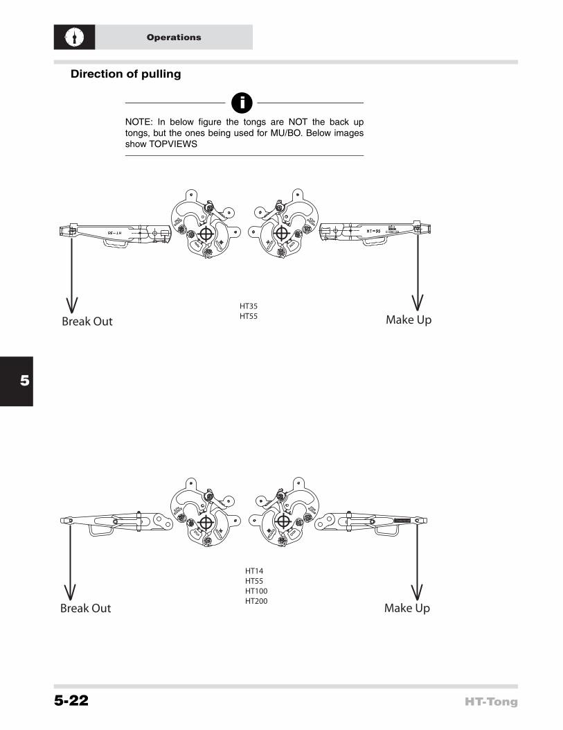
Direction of pulling
iNOTE: In below figure the tongs are NOT the back uptongs, but the ones being used for MU/BO. Below imagesshow TOPVIEWS
HT35HT55
HT14HT55HT100HT200
Make Up
Make Up
Break Out
Break Out

6
Assembly
HT-Tong 6-23
Assembly and dis-assemblyHead assembly procedureProcedure
1. Disconnect the head assembly from the lever by removing the hinge pins and lock
2. Disconnect the latch by removing the hinge pin . This allows removal of the latch spring and latch spring plunger.
3. For HT 55 and HT35 tongs remove the latch jaw by removing the hinge pin. This will allow removal of the adjustable stop assembly and booster plunger assembly.
4. Remove all other lug, hinge, short and long jaws by taking out the various hinge pins.
5. Complete disassembly of the various jaws can be done by removing all nuts and bolts.
Disassembly of the hanger and lever assemblyProcedure
1. Disconnect the hanger assembly from the lever by removing the hanger bolt and nut
2. Complete disassembly of the hanger and lever can be carried out by removing all nuts and bolts.
!CAUTION: Ensure that the orientation of the parts iscorrect while assembling the HT-tong. For proper order ofinstallation of parts, see exploded views in chapter“Drawings”
Watch orientation of lugs and jaws.

6
Assembly
6-24 HT-Tong

7
Troubleshooting
HT-Tong 7-25
Trouble shooting When problems cannot be solved, contact an authorized Varco repair facility
Overview possible problems
Problem Possible cause Possible solution
Tong does not bite Worn die Replace die
Tong not correctly dressed for sizeCheck manual for correct dressing for size
Tong assembled wrongly Reassemble tong properly
Tong does not hang level
Balancing (eye) bolt not adjusted properly
Adjust balancing (eye) bolt
Tong does not open OR parts do not move freely.
Yielding due to overload Replace tong
Bent pins or sheared pin heads
Tong is overloaded Replace tong
Elongated holes Tong is overloaded Replace tong
Tong holes worn
Check amount of wear. If within acceptance criteria use as is, when over acceptance criteria, replace tong

7
Troubleshooting
7-26 HT-Tong

8
Appendix
HT-Tong 8-27
AppendixesSummary of risk assessment
Identified potential hazard Point of failure Result
Chain/cable/pull line overtensioned Breaking of chain/cable/pull line This may cause the tong rotate uncontrollable,
hitting everything in it's way.
Chain/cable/pull line overtensioned Breaking of chain/cable/pull line Cable releases energy, flying all over the place
Pulling too hard relative to tong (wrong tong being used) Failing or breaking tong.
The tong being used may break because of too small tong utilized, resulting in tong debris flying around all over the place.
Pinch points due to other devices in work area of tong (e.g. back up tong on the same level))
Device collides with HT-tong Crushing hand/fingers/limps/body
Applying tong too low to floor No control over tong(s) Crushing hands/limps
MU Tong too close to Back Up tong Dangerously close Crushing / shearing hands/limps
Tong line connection failure Breaking of pin / lever/snub line saver
This may cause the tong rotateuncontrollable, hitting everything in it's way.
Failing tong line retention Breaking tong line retainer boltThis may cause the line to break free from the tong when tensioning, resulting in not being able to apply torque
Cable releases energy, flying all over the place
Snub line saver break Breaking parts/bolts/u-clamp This may cause the tong rotate uncontrollable, hitting everything in it's way
Missing nameplate Not using proper size tongThe tong being used may break because of too small tong utilized, resulting in tong debris flying around all over the place
Breaking lever Not checked during inspection schedule (MPI) Tong debris may fly around all over the place
Breaking / missing hanger bolt Not checked during inspection schedule Tong may drop to the floor
Breaking hanger Not checked during inspection schedule Tong may drop to the floor
Missing / loose hanger adjustment screw
Not checked during inspection schedule Tong may be hard to handle during run
Missing/failing balancing screw bolt
Not checked during inspection schedule Tong may drop to the floor
Breaking suspension ring Not checked during inspection schedule Tong may drop to the floor
Missing grease nipples
No proper lubrication of hinge pins results in worn out bores/pins Tong may be hard to handle during run
Tong pins may break due to wear
Tong parts may break due to wear
Breaking jaws or latch Not checked during inspection schedule (MPI) Tong debris may fly around all over the place.
Slipping dies Inserts worn out. Tong may slip and make unexpected movement
Coupling may not be made up properly, resulting of loosing pipe
Missing handle bolts Loose nuts Pinch points as operator will grab other parts
Missing protective hose around handle bolts Worn hose May cause uncomfortable situation
Missing nuts of hinge pin(s) Not checked during inspection schedule
May cause dangerous situation as hinge pin failure may occur
Missing hinge pin(s) Missing nut/dowel pin Not being able to use tong
Missing dowel pins of hinge pin nuts
Not checked during inspection schedule
May cause dangerous situation as hinge pin failure may occur
Missing/failing springs Not checked during functional check Latch may not close easily

8
Appendix
8-28 HT-Tong
General conclusionsEnsure training is carried out
Ensure rig procedures are in place and followed up
Carry out inspection according to manual
Work according to procedures in manual
Ensure snub-line saver is in place with safety line
Personnel must stay out of working area of tong
Wear personal safety equipment
Identified potential hazard SYSTEM
Point of failure Result
Missing dies Missing cotter pin/retainer pins Tong may slip and make unexpected movement
Coupling may not be made up properly resulting of loosing pipe
Breaking dies Overload/wear Tong may slip and make unexpected movement
Coupling may not be made up properly resulting of loosing pipe
Flying debris
Breaking dies Not properly latched/wrong size tong
Tong may slip and make unexpected movement
Coupling may not be made up properly resulting of loosing pipe
Flying debris
Pinch points Grabbing at restricted areas Pinching/loosing fingers
As a result of failing other parts Pinching/loosing fingers/limps/death
Flying debris from breaking dies Worn dies Eye puncture / hit by debris
Splinters/burrs Cutting from pipe/dies Finger punctures
Falling tong Failing suspension Bruises/fractures
Wrong assembly of tong Failing MU or BO Unexpected movements of tong

8
Appendix
HT-Tong 8-29
Torque values (US) for bolts
Tensile Strength = 120,000 psi to 1” dia. Proof Strength = 85,000 psi
Tensile Strength = 120,000 psi to 1” dia. Proof Strength = 85,000 psi
Bolts Lubricated with Light Machine Oil Grade 8
Bolts lubricated with Anti-seize compound Grade 8
Dia. Threads per inch
Min. Torque(ft lb)
Max.Torque(ft lb)
Clamp force(lb)
Min. Torque(ft lb)
Max.Torque(ft lb)
Clamp force(lb)
Coarse Thread Series, UNC1/4” 20 11.4 12.6 2860 8.6 9.5 28605/16” 18 24 26 3720 17.8 19.7 37203/8” 16 43 47 7000 32 35 70007/16” 14 67 74 9550 50 55 95501/2” 13 105 116 12750 78 87 127509/16” 12 143 158 16100 107 118 161005/
8” 11 209 231 20350 157 173 203503/4” 10 361 399 30100 271 299 301007/8” 9 570 630 41600 428 473 41600
1” 8 855 945 54500 641 709 54400
1 1/8” 7 1216 1344 68700 912 1008 68700
1 1/4” 7 1729 1911 87200 1297 1433 87200
1 3/8” 6 2261 2499 104000 1696 1874 104000
1 1/2” 6 3002 3318 126500 2252 2489 126500
Bolts Lubricated with Light Machine Oil Grade 8
Bolts lubricated with Anti-seize compound Grade 8
Dia. Threads per inch
Min. Torque(ft lb)
Max.Torque(ft lb)
Clamp force(lb)
Min. Torque(ft lb)
Max.Torque(ft lb)
Clamp force(lb)
Fine Thread Series, UNF1/4” 28 13.3 14.7 3280 10 11 32805/16” 24 24 26 5220 17.8 19.7 52203/8” 24 48 53 7900 36 39 79007/16” 20 76 84 10700 57 63 107001/2” 20 114 126 14400 86 95 144009/16” 18 162 179 18250 121 134 182505/
8” 18 228 252 23000 171 189 230003/4” 16 399 441 33600 299 331 336007/8” 14 627 693 45800 470 520 45800
1” 14 950 1050 59700 713 788 59700
1 1/8” 12 1368 1512 77000 1026 1134 77000
1 1/4” 12 1900 2100 96600 1425 1565 96600
1 3/8” 12 2584 2856 118400 1938 2142 118400
1 1/2” 12 3382 3738 142200 2537 2804 142200

8
Appendix
8-30 HT-Tong
Torque values (metric) for bolts
Bolts Lubricated with Light Machine Oil Grade 8
Bolts lubricated with Anti-seize compound Grade 8
Diameter
Threads per inch
Min. Torque(Nm)
Max.Torque(Nm)
Clamp force(N)
Min. Torque(Nm)
Max.Torque(Nm)
Clamp force(N)
Coarse Thread Series, UNC1/4” 20 15.5 17.1 12870 11.7 12.9 128705/16” 18 32.6 35.4 16740 24.2 26.8 167403/8” 16 58.5 64 32500 43.5 47.6 315007/16” 14 91.1 100.6 42980 68 92.5 429801/2” 13 143 158 57380 106 118 573809/16” 12 195 215 72450 145.5 160 724505/
8” 11 284 314 91580 213.5 235 915803/4” 10 491 542 135450 368 407 1354507/8” 9 775 857 187200 582 643 187200
1” 8 1163 1285 245250 872 965 245250
1 1/8” 7 1654 1828 309150 1240 1370 309150
1 1/4” 7 2351 2598 382400 1764 1949 392400
1 3/8” 6 3075 3398 468000 2306 2549 468000
1 1/2” 6 4082 4512 569250 3062 3385 569250
Bolts Lubricated with Light Machine Oil Grade 8
Bolts lubricated with Anti-seize compound Grade 8
Diameter
Threads per inch
Min. Torque(Nm)
Max.Torque(Nm)
Clamp force(N)
Min. Torque(Nm)
Max.Torque(Nm)
Clamp force(N)
Fine Thread Series, UNF1/4” 28 18.1 20 14760 13.6 15 147605/16” 24 32.6 35 23490 24.2 26.8 234903/8” 24 65.3 72 35550 49 53 355507/16” 20 103 114 48150 77.5 86 481501/2” 20 155 171 64800 117 129 648009/16” 18 220 239 82130 165 182 821305/
8” 18 310 343 103500 232 257 1035003/4” 16 542 600 151200 406 450 1512007/8” 14 853 943 206100 639 707 206100
1” 14 1292 1428 268650 970 1071 268650
1 1/8” 12 1860 2056 346500 1396 1542 346500
1 1/4” 12 2584 2856 434700 1938 2128 434700
1 3/8” 12 3514 3884 532800 2635 2913 532800
1 1/2” 12 4599 5083 639900 3450 3813 639900

9
Drawings
HT-Tong 9-31
Drawings and Parts Break DownAdded parts jaw assemblies
iNOTE: In the exploded views on the following pages,several parts, especially the jaw assemblies, are notshowed. In this chapter you will find these parts.
TOPVIEW
Handle bolt
Flat washer
Plastic safety cap
Grip hose
Plastic safety cap
BOTTOM VIEW
Flat washer
Self locking nut

9
Drawings
9-32 HT-Tong
HT-14 additional parts
HT-35 additional parts
HT-55 additional parts
HT-65 additional parts
Per grip point
Qty Name Part number1 Handle bolt 50010-52-C8
1 Grip hose 203439
1 Nut, self locking 51850-10-C
2 Plastic safety cap 250369
2 Washer, flat 50810-R-C
Per grip point
Qty Name Part number1 Handle bolt 50010-52-C8
1 Handle bolt (long jaw) 50010-60-C8
1 Grip hose 203439
1 Nut 51850-10-C
2 Plastic safety cap 250369
2 Flat washer 50810-R-C
Per grip point
Qty Name Part number1 Handle bolt 50010-60-C8
1 Grip hose 203439
1 Nut, self locking 51850-10-C
2 Plastic safety cap 250369
2 Washer flat 50810-R-C
Per grip point
Qty Name Part number1 Handle bolt 50010-60-C8
1 Handle bolt (short jaw) 50010-54-C8
1 Grip hose 203439
1 Nut, self locking 51850-10-C
2 Plastic safety cap 250369
2 Washer flat 50810-R-C

9
Drawings
HT-Tong 9-33
HT-100 additional parts
HT-200 additional parts
Per grip point
Qty Name Part number1 Handle Bolt 50010-60-C8
1 Grip hose 203439
1 Nut, self locking 51850-10-C
2 Plastic safety cap 250369
2 Washer flat 50810-R-C
Per grip point
Qty Name Part number1 Handle bolt 50010- 76-C8
1 Grip hose 203439
1 Nut, self locking 51850-10-C
2 Plastic safety cap 250369
2 Washers, flat 50810-R-C

9
Drawings
9-34 HT-Tong
Parts lists and exploded viewsParts list HT 14 manual tong
Item. No No. Req Description Part no. Item. No No. Req Description Part no.
1 Lever ass’y 200641-1 25 1 Plunjer pin 23922
1 1 Lever (note 1) 26 1 Grease fitting 53201
2 1 Tong line pin retainer 23918
3 1 Safety line bolt 939099-204 27 1 Latch spring 23920
4 1 Safety line bolt nut 50508-C 28 4 Hinge pin 200649
5 1 Cotter pin 51402-8 29 4 Hinge pin nut 8150
6 1 Name plate 26119-1 30 4 Cotter pin 51435-20
7 4 Drive screw 53301-4-5 Range 2 3/8"- 3 1/2"
8 2 Grease fitting 53201 1 Lug jaw ass’y 200645-1
1 Hanger ass’y 200650-1 31 1 Lug jaw (note 1)
9 1 Hanger (note 1) 32 1 Grease fitting 53201
10 1 Hanger bolt 939099-165 Range 3 1/2"- 5"
11 1 Hanger bolt nut 50510-C 1 Lug jaw ass’y 200646-1
12 1 Cotter pin 51402-12 31 1 Lug jaw (note 1)
13 1 Hanger adjustment screw 939168-96 32 1 Grease fitting 53201
14 1 Hanger jam nut 50312-C Range 4 3/4"-6 1/4"
1 Lug jaw ass’y 200647-1
1 Long jaw ass’y 200642-1 31 1 Lug jaw (note 1)
15 1 Long jaw (note 1) 32 1 Grease fitting 53201
16 1 Die 16401-6 Range 5 3/4"-7"
17 2 Retainer pin BJ 17194 1 Lug jaw ass’y 200648-1
18 2 Cotter pin 51402-6 31 1 Lug jaw (note 1)
1 Short jaw ass’y 200643-1 32 1 Grease fitting 53201
19 1 Short jaw (note 1) Not in drawing
20 1 Die 16401-6 - - Warning label 201350
21 2 Retainer pin BJ 17194 - - Warning label 52319
22 2 Cotter pin 51402-6
1 Latch ass’y 200644-1
23 1 Latch (note 1) For part numbers gripping points see page 9-3224 1 Latch spring plunger 23915 Note 1: Available as ass’y only

9
Drawings
HT-Tong 9-35
Exploded view HT-14

9
Drawings
9-36 HT-Tong
Parts list HT 35 manual tongItem.No No. Req Description Part no. Item. No No. Req Description Part no.
1 Long lever ass’y 200621-1 1 Latch ass’y 200626-1
1 1 Long lever (note 1) 33 1 Latch (note 1)
1 Short lever ass’y 200622-1 34 1 Hinge pin nut 200632
1 1 Short lever (note 1) 35 2 Groove pin 51506-8
2 1 Tong line pin 200633
3 1 Tong line pin retainer 25468 36 2 Latch spring 9561
4 1 Safety line bolt 50012-56-C8 37 1 Hinge pin block 200631
5 1 Safety line bolt nut 50512-C 38 4 Hinge pin threaded 200629
6 1 Cotter pin 51402-16 39 4 Dowel pin 11199
7 1 Name plate 26119-1 40 4 Cotter pin 51402-6
8 4 Drive screw 53301-4-5 Range 2 3/8"-3 11/16"
9 2 Grease fitting 53201 1 Lug jaw ass’y 200076-1
16 1 Hanger bolt 939099-108 41 1 Lug jaw (note 1)
17 1 Hanger bolt nut 50216-C Range 2 7/8"-4 1/4"
18 1 Cotter pin 51402-14 1 Lug jaw ass’y 200077-1
1 Hanger ass’y 200630-1 41 1 Lug jaw (note 1)
10 1 Hanger (note 1) Range 3 1/2"-5 1/4"
11 1 Balancing screw 12586 1 Lug jaw ass’y 200078-1
12 1 Balancing screw bolt 939099-596 41 1 Lug jaw (note 1)
13 1 Balancing screw bolt nut 50512-C Range 5 1/4"-7"
14 1 Cotter pin 51402-16 1 Lug jaw assy 200079-1
15 1 Suspension ring BJ 12863 41 1 Lug jaw (note 1)
19 1 Hanger adjustment screw 203438-1 Range 7"-8 5/8"
20 2 Hanger jam nut 50314-C - 1 Hinge & Lug jaw ass’y (not shown) 200080-2
1 Long jaw ass’y 200623-1 - 1 Hinge jaw ass’y (not shown) 200627-1
21 1 Long jaw (note 1) Range 7"-8 5/8"
22 1 Die 16401-6 1 Lug jaw ass’y 200080-1
23 2 Retainer pin BJ 17194 41 1 Lug jaw (note 1)
24 2 Cotter pin 51402-6 Range 9 5/8"-10 3/4"
25 1 Hinge pin nut 200632 - 1 Hinge & Lug jaw ass’y (not shown) 200081-2
26 2 Groove pin 51506-8 - 1 Hinge ass’y (not shown) 200628-1
1 Short jaw ass’y 2 3/8"-7" 200625-1 Range 9 5/8"-10 3/4"
27 1 Short jaw 2 3/8"-7" (note 1) 41 1 Lug jaw ass’y 200081-1
1 Short jaw ass’y 7 5/8"- 10 3/4" 200624-1 41 1 Lug jaw (note 1)
27 1 Short jaw 7 5/8"- 10 3/4" (note 1) 42 1 Die 16402-6
28 2 Die 16401-6 43 2 Retainer pin BJ 17194
29 4 Retainer pin BJ 17194 44 2 Cotter pin 51402-6
30 4 Cotter pin 51402-6 45 2 Grease fitting 53201
31 2 Hinge pin nut 200632 Not in drawing
32 4 Groove pin 51506-8 - - Warning label 52319
- - Warning label 201350
Note 1: Available as ass’y only For part numbers gripping points, see page 9-32

9
Drawings
HT-Tong 9-37
Exploded view HT-35

9
Drawings
9-38 HT-Tong
Parts list HT 55 manual tongItem. No No. Req Description Part no. Item. No No. Req Description Part no.
1 Long lever ass’y 200561-1 1 Latch jaw ass’y 200566-1
1 1 Long lever (note 1) 39 1 Latch jaw (note 1)
1 Short lever ass’y 200562-1 40 1 Die 16402-6
1 1 Short lever (note 1) 41 2 Retainer pin BJ 17194
2 1 Tong line pin 200570 42 2 Cotter pin 51402-6
3 1 Tong line pin retainer 25468 43 2 Grease fitting 53201
4 1 Name plate 200568 1 Latch ass’y 200565-1
5 4 Drive screw 53301-4-5 44 1 Latch (note 1)
6 2 Grease fitting 53201 45 1 Hinge pin nut 200572
13 1 Hanger bolt 939099-556 46 2 Groove pin 51506-8
14 1 Hanger bolt nut 50512-C 47 2 Latch spring 9561
15 1 Cotter pin 51402-16 48 1 Hinge pin block 200569
1 Hanger ass’y 203344-36 49 5 Hinge pin threaded 200567
7 1 Hanger (note 1 & 2) 50 5 Dowel pin 11199
8 1 Balancing screw 12586 51 5 Cotter pin 51402-6
9 1 Balancing screw bolt 939099-596 Range 3 1/2" - 5"
10 1 Balancing screw bolt nut 50512-C 1 Lug jaw ass’y 200083-1
11 1 Cotter pin 51402-16 52 1 Lug jaw (note 1)
12 1 Suspension ring BJ 12863 Range 5" - 6 3/4"
16 1 Hanger adjustment screw 203438-1 1 Lug jaw ass’y 200084-1
17 2 Hanger jam nut 50314-C 52 1 Lug jaw (note 1)
1 Long jaw ass’y 200563-1 Range 6 5/8" - 9"
18 1 Long jaw (note 1) 1 Lug jaw ass’y 200085-1
19 1 Adjustable stop 11139 52 1 Lug jaw (note 1)
20 1 Adjustable stop plunger 11144 Range 9" - 10 3/4"
21 1 Adjustable stop spring 11192 1 Lug jaw ass’y 200086-1
22 1 Adjustable stop bolt 11191 52 1 Lug jaw (note 1)
23 1 Adjustable stop bolt nut 8150 Range 11 3/4"
24 1 Cotter pin 51402-14 1 Lug jaw ass’y 200087-1
25 1 Booster plunger 200571 52 1 Lug jaw (note 1)
26 1 Booster plunger spring 11229 Range 12 3/4" - 13"
27 1 Booster spring ret. plug 53000-16 1 Lug jaw ass’y 200089-1
28 1 Die 16402-6 52 1 Lug jaw (note 1)
29 2 Retainer pin BJ 17194 Range 13 3/8"
30 2 Cotter pin 51402-6 1 Lug jaw ass’y 200090-1
31 2 Hinge pin nut 200572 52 1 Lug jaw (note 1)
32 4 Groove pin 51506-8 53 1 Die 16402-6 *
1 Short jaw ass’y 200564-1 54 2 Retainer pin BJ 17194 *
33 1 Short jaw (note 1) 55 2 Cotter pin 51402-6 *
34 2 Die 16402-6 56 1 Grease fitting 53201
35 4 Retainer pin BJ 17194 Not in drawing
36 4 Cotter pin 51402-6 - - Warning label 52319
37 2 Hinge pin nut 200572 - - Warning label 201350
38 2 Groove pin 51506-8 For grip points, see page 9-32
Note 1: Available as ass’y only , * = from 11 3/4” die only Note 2: Also available in lenght of 48” and 96”

9
Drawings
HT-Tong 9-39
Exploded view HT55

9
Drawings
9-40 HT-Tong
Part list HT 65 manual tongItem No No. Req Description Part no. Item No No. Req Description Part no.
1 Lever ass’y 200541-1 36 1 Latch spring 24525
1 1 Lever (note 1) 37 4 Hinge pin 200550
2 1 Tong line retainer 24529 38 4 Hinge pin nut 24528
3 1 Tong line retainer bolt 24249 39 4 Cotter pin 51405-24-S
4 1 Plain washer 50809-N-C Range 3 1/2" - 8 1/4"
5 1 Cotter pin 51402-8 1 Lug jaw ass’y 200546-1
6 1 Name plate 200551 40 1 Lug jaw (note 1)
7 4 Drive screw 53301-4-5 41 1 Die 16402-6
8 2 Grease fitting 53201 42 2 Die retaining pin BJ 17194
15 1 Hanger bolt 939099-546 43 2 Cotter pin 51402-6
16 1 Hanger bolt nut 50512-C 44 2 Grease fitting 53201
17 1 Cotter pin 51402-6 Range 8" - 11 1/4"
1 Hanger ass’y 203344-36 1 Lug jaw ass’y 200547-1
9 1 Hanger (note 1&2) 40 1 Lug jaw (note 1)
10 1 Balancing screw 12586 44 2 Grease fitting 53201
11 1 Balancing screw bolt 939099-596 Range 11 3/4" - 14 3/8"
12 1 Balancing screw bolt nut 50512-C 1 Lug jaw ass’y 200548-1
13 1 Cotter pin 51402-16 40 1 Lug jaw (note 1)
14 1 Suspension ring BJ 12863 Range 16" - 17"
18 1 Hanger adjustment screw 203438-1 1 Lug jaw ass’y 200549-1
19 2 Hanger jam nut 50314-C 40 1 Lug jaw (note 1)
1 Long jaw ass’y 200542-1 1 Hinge jaw ass’y 8 1/2" - 17" 200545-1
20 1 Long jaw (note 1) 45 1 Hinge jaw (note 1)
21 2 Die 16402-6 46 3 Grease fitting 53201
22 4 Retaining pin BJ 17194 47 1 Hinge pin 200550
23 4 Cotter pin 51402-6 48 1 Hinge pin nut 24528
1 Short jaw ass’y 200543-1 49 1 Cotter pin 51405-24
24 1 Short jaw (note 1) Not in drawing
25 1 Die 16402-6 - - Warning label 52319
26 2 Retainer pin BJ 17194 - - Warning label 201350
27 2 Cotter pin 51402-6
28 1 Short jaw handle 25864
29 1 Bolt 50012-52-C8
30 1 Nut 50212-C
31 1 Lock washer 50912-C
1 Latch ass’y 200544-1
32 1 Latch (note 1)
33 1 Latch spring plunger 24526 For part numbers grip points, see page 9-3234 1 Plunger pin 24530 Note 1: Available as ass’y only35 1 Grease fitting 53201 Note 2: Also available in lenght of 48” and 96”

9
Drawings
HT-Tong 9-41
Exploded view HT-65
9
Drawings
9-42 HT-Tong
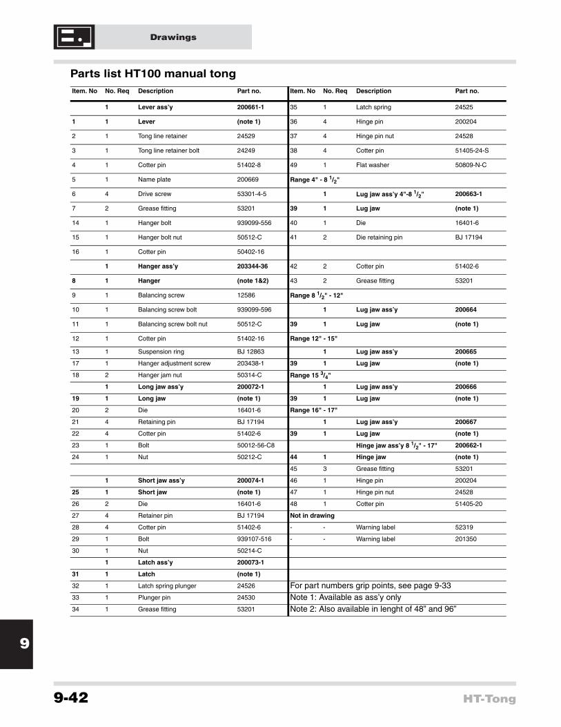
Parts list HT100 manual tong Item. No No. Req Description Part no. Item. No No. Req Description Part no.
1 Lever ass’y 200661-1 35 1 Latch spring 24525
1 1 Lever (note 1) 36 4 Hinge pin 200204
2 1 Tong line retainer 24529 37 4 Hinge pin nut 24528
3 1 Tong line retainer bolt 24249 38 4 Cotter pin 51405-24-S
4 1 Cotter pin 51402-8 49 1 Flat washer 50809-N-C
5 1 Name plate 200669 Range 4" - 8 1/2"
6 4 Drive screw 53301-4-5 1 Lug jaw ass’y 4"-8 1/2" 200663-1
7 2 Grease fitting 53201 39 1 Lug jaw (note 1)
14 1 Hanger bolt 939099-556 40 1 Die 16401-6
15 1 Hanger bolt nut 50512-C 41 2 Die retaining pin BJ 17194
16 1 Cotter pin 50402-16
1 Hanger ass’y 203344-36 42 2 Cotter pin 51402-6
8 1 Hanger (note 1&2) 43 2 Grease fitting 53201
9 1 Balancing screw 12586 Range 8 1/2" - 12"
10 1 Balancing screw bolt 939099-596 1 Lug jaw ass’y 200664
11 1 Balancing screw bolt nut 50512-C 39 1 Lug jaw (note 1)
12 1 Cotter pin 51402-16 Range 12" - 15"
13 1 Suspension ring BJ 12863 1 Lug jaw ass’y 200665
17 1 Hanger adjustment screw 203438-1 39 1 Lug jaw (note 1)
18 2 Hanger jam nut 50314-C Range 15 3/4"
1 Long jaw ass’y 200072-1 1 Lug jaw ass’y 200666
19 1 Long jaw (note 1) 39 1 Lug jaw (note 1)
20 2 Die 16401-6 Range 16" - 17"
21 4 Retaining pin BJ 17194 1 Lug jaw ass’y 200667
22 4 Cotter pin 51402-6 39 1 Lug jaw (note 1)
23 1 Bolt 50012-56-C8 Hinge jaw ass’y 8 1/2" - 17" 200662-1
24 1 Nut 50212-C 44 1 Hinge jaw (note 1)
45 3 Grease fitting 53201
1 Short jaw ass’y 200074-1 46 1 Hinge pin 200204
25 1 Short jaw (note 1) 47 1 Hinge pin nut 24528
26 2 Die 16401-6 48 1 Cotter pin 51405-20
27 4 Retainer pin BJ 17194 Not in drawing
28 4 Cotter pin 51402-6 - - Warning label 52319
29 1 Bolt 939107-516 - - Warning label 201350
30 1 Nut 50214-C
1 Latch ass’y 200073-1
31 1 Latch (note 1)
32 1 Latch spring plunger 24526 For part numbers grip points, see page 9-3333 1 Plunger pin 24530 Note 1: Available as ass’y only34 1 Grease fitting 53201 Note 2: Also available in lenght of 48” and 96”

9
Drawings
HT-Tong 9-43
Exploded view HT-100

9
Drawings
9-44 HT-Tong
Parts list HT 200 manual tongItem. No No. Req Description Part no. Item. No No. Req Description Part no.
1 Lever ass’y 200501-1 Opt. 1 Air lift ass’y 30041-1
1 1 Lever (note 1) Range 6"-7 7/8"
2 1 Tong line retainer 24529 1 Lug jaw ass’y 200506-SP
3 1 Tong line retainer bolt 24249 36 1 Lug jaw (note 1)
4 1 Cotter pin 51402-8 37 1 Coarse die 33562
5 2 Grease fitting 53201 38 10 Die retainer spirol pin 51405-16
12 1 Hanger bolt 939099-801 39 2 Grease fitting 53201
13 1 Hanger bolt nut 50514-C 1 Die carrier(range 6" to 7-7/8" ; not shown) 200512
14 1 Cotter pin 51402-16 Range 8"-9 5/8" or 11 1/2"-13 1/4"
1 Hanger ass’y 203344-48 1 Lug jaw ass’y 200506-1
6 1 Hanger (note 1) 36 1 Lug jaw (note 1)
7 1 Balancing screw 12586 37 1 Coarse die 33562
8 1 Balancing screw bolt 939099-596 38 2 Die retainer spirol pin 947129-194
9 1 Balancing screw bolt nut 50512-C 39 2 Grease fitting 53201
10 1 Cotter pin 51402-16 Range 9 1/2"-11 1/8" or 13"-14 3/4"
11 1 Suspension ring BJ 12863 1 Lug jaw ass’y 200507-1
15 1 Hanger adjustment screw 203438 36 1 Lug jaw (note 1)
16 2 Hanger jam nut 50314-C
1 Long jaw ass’y 200502-1 39 2 Grease fitting 53201
16 1 Long jaw (note 1) Range 11"-12 1/2" or 14 3/8"-16"
17 2 Coarse die 33562 1 Lug jaw ass’y 200508-1
18 2 Die retainer spirol pin 947129-194 36 1 Lug jaw (note 1)
19 2 Grease fitting 53201 39 2 Grease fitting 53201
21 1 Hinge pin nut 200510 1 Hinge jaw ass’y 11 1/2"-16" 200505-1
22 2 Groove pin 51506-8 40 1 Hinge jaw (note 1)
1 Short jaw ass’y 200503-1 41 2 Grease fitting 53201
22 1 Short jaw (note 1) 42 1 Hinge pin 200509
23 2 Coarse die 33562 43 1 Clevis pin 56405-40-SHP
24 2 Die retainer spirol pin 947129-194 44 1 Cotter pin 51402-8
25 4 Hinge pin nut 200510 45 1 Hinge pin nut 200510
26 2 Groove pin 51506-8 46 2 Groove pin 51506-8
1 Latch ass’y 200504-1 Not in drawing
27 1 Latch (note 1) - - Warning label 201350
28 1 Latch clevis 33561 - - Warning label 52319
29 1 Latch clevis pin 33563
30 1 Hinge pin nut 200510
31 2 Groove pin 51506-8
32 1 Latch clevis spring 33570
33 4 Hinge pin 200509
34 4 Clevis pin 56405-40-SHP For part numbers grip points, see page 9-3335 4 Cotter pin 51402-8 Note 1: Available as ass’y only47 1 Flat washer 50809-N-C Note 2: Also available in lenght of 48” and 96”

9
Drawings
HT-Tong 9-45
Exploded view HT-200

9
Drawings
9-46 HT-Tong
Parts list HT 50 casing head assembliesFig. A Fig. B Fig.C Fig. D Fig.E Fig F Fig G Fig.H
pn# 200580-1 200580-2 200580-3 200580-4 200580-5 200580-6 200580-7 200580-8
Ref. Description No. req. No. req. No. req. No. req. No. req. No. req. No. req. No. req. pn#
1 Lever ass’y
2 Long jaw ass’y 1 1 1 1 1 1 1 1 200581-1
3 Short jaw ass’y 1 1 1 1 1 1 1 1 200582-1
4 Latch jaw ass’y 1 1 1 1 1 1 1 1 2005831-1
5 Latch ass’y 1 1 1 1 1 1 1 1 200565-1
6 Latch lug jaw ass’y 1 1 1 1 1 1 1 1 200587-1
7 Hinge jaw ass’y A - 1 - 1 2 1 2 2 200584-1
8 Hinge jaw ass’y B 1 1 1 1 1 1 1 1 200585-1
9 Hinge jaw ass’y C 1 - 2 1 - 2 1 2 200586-1
- Hinge pin block 1 1 1 1 1 1 1 1 200569
- Latch spring 2 2 2 2 2 2 2 2 9561
- Hinge pin threaded 7 7 8 8 8 9 9 10 200567
- Dowel pin 7 7 8 8 8 9 9 10 11199
- Cotter pin 7 7 8 8 8 9 9 10 51402-6
- Hinge pin nut 7 7 8 8 8 9 9 10 200572
- Die 2 2 2 2 2 2 2 2 16402-6
- Handle bolt 4 4 4 4 4 4 4 4 50010-54-C8
- Nut 4 4 4 4 4 4 4 4 50510-C
- Rubber hose 4 4 4 4 4 4 4 4 203439
- Cotter pin 4 4 4 4 4 4 4 4 51435-12
- Warning label 1 1 1 1 1 1 1 1 201350
Fig I. Fig J Fig. K Fig. L Fig. M Fig. N Fig.O
200600-1 200600-2 200600-3 200600-4 200600-5 200600-6 200600-7
Ref. Description No. req. No. req. No. req. No. req. No. req. No. req. No. req. Part no.
1 Lever ass’y
2 Long jaw ass’y 1 1 1 1 1 1 1 200601-1
3 Short jaw ass’y 1 1 1 1 1 1 1 200602-1
4 Latch jaw ass’y 1 1 1 1 1 1 1 200603-1
5 Latch ass’y 1 1 1 1 1 1 1 200565-1
6 Latch lug jaw ass’y 1 1 1 1 1 1 1 200607-1
7 Hinge jaw ass’y D 3 4 3 4 3 2 2 200604-1
8 Hinge jaw ass’y E 1 1 3 2 2 2 5 200605-1
9 Hinge jaw ass’y F 1 - - - 2 4 1 200606-1
- Hinge pin block 1 1 1 1 1 1 1 200569
- Latch spring 2 2 2 2 2 2 2 9561
- Hinge pin threaded 10 10 11 11 12 13 13 200567
- Dowel pin 10 10 11 11 12 13 13 11199
- Cotter pin 10 10 11 11 12 13 13 51402-6
- Hinge pin nut 10 10 11 11 12 13 13 200572

9
Drawings
HT-Tong 9-47
Fig I. Fig J Fig. K Fig. L Fig. M Fig. N Fig.O
200600-1 200600-2 200600-3 200600-4 200600-5 200600-6 200600-7
Ref. Description No. req. No. req. No. req. No. req. No. req. No. req. No. req. Part no.
- Die 2 2 2 2 2 2 2 16402-6
- Handle bolt 4 4 4 4 4 4 4 50010-54-C8
- Nut 4 4 4 4 4 4 4 50510-C
- Rubber hose 4 4 4 4 4 4 4 203439
- Cotter pin 4 4 4 4 4 4 4 51435-12
- Warning label 1 1 1 1 1 1 1 201350
Range Casing head assy pn# Range Casing head assy pn# Range Casing head assy pn#
13 3/8” to 14 1/2” 200580-1 20” to 21 1/2” 200580-6 28 1/2” to 30”200600-3
14 1/2” to 16” 200580-2 21 1/2” to 23” 200580-7 30” to 31 5/8” 200600-4
16” to 17 1/2” 200580-3 24” to 251/2” 200580-8 31 1/2” to 33” 200600-5
17 1/2” to 19” 200580-4 25 1/2” to 27” 200600-1 33” to 34 1/2” 200600-6
19” to 20” 200580-5 27” to 17 1/2” 200600-2 34 1/2” to 36” 200600-7

9
Drawings
9-48 HT-Tong
Casing head assemblies overview

9
Drawings
HT-Tong 9-49
Critical area drawings

9
Drawings
9-50 HT-Tong

9
Drawings
HT-Tong 9-51

9
Drawings
9-52 HT-Tong

9
Drawings
HT-Tong 9-53

9
Drawings
9-54 HT-Tong

9
Drawings
HT-Tong 9-55

9
Drawings
9-56 HT-Tong