
UNITY 2 installation manual v1.3 - Agilent
18
UNITY 2 Installation Manual 1 UNITY 2 TM Installation Manual Version 1.3 (Changes: Sections 2.2 & 2.7) June 2009 1. UNITY 2 Pre-installation Check List ........................................................................... 2 1.1. Minimum computer specification for UNITY 2 control ............................................ 2 1.2. GC equipment requirements .............................................................................. 2 1.3. Access into the GC oven.................................................................................... 2 1.4. GC configuration/parameter selection ................................................................. 2 1.5. Laboratory location........................................................................................... 3 1.5.1. Space requirements ................................................................................... 3 1.5.2. Quality of the laboratory air ........................................................................ 3 1.5.3. Quality of the laboratory gas lines ............................................................... 3 1.6. Services .......................................................................................................... 3 1.6.1. Power ...................................................................................................... 3 1.6.2. Pressure controlled supply of dry air or nitrogen (purge gas) .......................... 3 1.6.3. Pressure controlled carrier gas supply .......................................................... 4 1.6.4. Filters ...................................................................................................... 4 1.6.5. UNITY 2 and Electronic Carrier Control (ECC) ................................................ 4 1.7. Unpacking UNITY 2 .......................................................................................... 4 2. Installing UNITY 2 ................................................................................................... 5 2.1. Installing the transfer line ................................................................................. 5 2.1.1. Installing the fused silica transfer line insert ................................................. 7 2.2. Connecting the transfer line to UNITY 2 .............................................................. 8 2.3. Installing the cold trap .................................................................................... 11 2.4. Connections to UNITY 2 .................................................................................. 15 2.5. Installing the software .................................................................................... 16 2.6. Running the software...................................................................................... 16 2.7. GC interface logic ........................................................................................... 17 2.8. Installation Checklist ...................................................................................... 18
Transcript of UNITY 2 installation manual v1.3 - Agilent

UNITY 2 Installation Manual 1
UNITY 2 TM Installation Manual Version 1.3 (Changes: Sections 2.2 & 2.7)
June 2009
1. UNITY 2 Pre-installation Check List ........................................................................... 2
1.1. Minimum computer specification for UNITY 2 control ............................................ 2
1.2. GC equipment requirements .............................................................................. 2
1.3. Access into the GC oven.................................................................................... 2
1.4. GC configuration/parameter selection ................................................................. 2
1.5. Laboratory location........................................................................................... 3
1.5.1. Space requirements................................................................................... 3
1.5.2. Quality of the laboratory air ........................................................................ 3
1.5.3. Quality of the laboratory gas lines ............................................................... 3
1.6. Services.......................................................................................................... 3
1.6.1. Power ...................................................................................................... 3
1.6.2. Pressure controlled supply of dry air or nitrogen (purge gas) .......................... 3
1.6.3. Pressure controlled carrier gas supply .......................................................... 4
1.6.4. Filters ...................................................................................................... 4
1.6.5. UNITY 2 and Electronic Carrier Control (ECC) ................................................ 4
1.7. Unpacking UNITY 2 .......................................................................................... 4
2. Installing UNITY 2................................................................................................... 5
2.1. Installing the transfer line ................................................................................. 5
2.1.1. Installing the fused silica transfer line insert ................................................. 7
2.2. Connecting the transfer line to UNITY 2 .............................................................. 8
2.3. Installing the cold trap.................................................................................... 11
2.4. Connections to UNITY 2 .................................................................................. 15
2.5. Installing the software .................................................................................... 16
2.6. Running the software...................................................................................... 16
2.7. GC interface logic........................................................................................... 17
2.8. Installation Checklist ...................................................................................... 18

UNITY 2 Installation Manual 2
1. UNITY 2 Pre-installation Check List
1.1. Minimum computer specification for UNITY 2 control
CPU 400MHz Pentium
RAM 64 MB
Free Disk Space 20 MB
Operating System Windows 95, 98, ME, 2000, NT4, XP (32-bit) and Vista (32-bit)
Minimum resolution 800x600
Other requirements Windows compatible mouse, at least one free serial comms port*
*The PC requires a free serial comms port for communication with UNITY 2. An additional
serial comms port is required for the following accessories:
• each ULTRA™ module (i.e. ULTRA, ULTRA 50:50™, AutoSecure ULTRA™)
• CIA8™ canister accessory
• series 1 Air Server™ (3, 6 or 8 channel)
• series 1 MFC
Note: Neither Series 2 Air Server (3 or 8 channel) nor Series 2 Mass Flow Controllers
(U-MFC100-2S, U-MFC200-2S) require additional serial ports
1.2. GC equipment requirements
UNITY 2 is usually connected to a gas chromatograph configured with appropriate conventional
or mass spectrometer (MS) detectors. No conventional GC injector is required for UNITY 2
operation. Ready and external start connections are required on the GC.
1.3. Access into the GC oven
The UNITY 2 heated transfer line is lined with 0.25 mm I.D., 0.35 mm O.D. uncoated
deactivated fused silica which butt connects with the capillary analytical column inside your GC
oven.
It is important that the heated and insulated portion of the transfer line extends as far as the
skin of the GC oven such that the GC oven heating begins at the point where heating of the
transfer line ends. A 25 mm diameter access hole is thus required into the GC, with a 6.5 mm
hole in the GC inner oven wall. Further information is provided in Section 2.1.
1.4. GC configuration/parameter selection
From a GC perspective, UNITY 2 may simply be regarded as a multipurpose, stand alone GC
injector for capillary or 1/8 inch packed columns. No conventional GC injector is required for
UNITY 2 operation. The rest of the GC system - column, oven, data handling, detector, etc. -
should be configured and used, as per normal chromatographic practice for the analytes of
interest.
If multiple applications are to be carried out or if samples are uncharacterised; for example
when monitoring unknown atmospheres, a good general purpose GC configuration comprises
25-30 m, 0.25mm or 0.32 mm ID, 1 or 2 µm phase thickness bonded methyl silicone capillary
column with a FID or mass spectrometer detector.

UNITY 2 Installation Manual 3
1.5. Laboratory location
1.5.1. Space requirements
UNITY 2 can sit either side of the gas chromatograph.
Efficient cold trap cooling requires at least a 10 cm gap on both sides of UNITY 2
1.5.2. Quality of the laboratory air
UNITY 2 is a powerful concentration device and is often used to determine trace levels of
organic analytes. It is advisable to store and operate UNITY 2 in a clean laboratory
environment with minimal atmospheric concentrations of organic vapours.
1.5.3. Quality of the laboratory gas lines
As UNITY 2 is a concentrator, even trace level contaminant’s in laboratory gas lines can
become significant interferents in the chromatograms produced.
Recommended gas lines are refrigeration-grade copper tubing connected using
approved swage-fittings.
Laboratory gas line joints and connections must never be brazed.
Position the gas supplies as close as possible to the analytical system i.e. such that the
gas lines are as short as possible.
Use a high quality, stainless steel diaphragm cylinder head regulator for the carrier gas
supply.
1.6. Services
1.6.1. Power
UNITY 2 is automatically compatible with all conventional mains power supplies ranging from
90 to 255 V and 50 or 60 Hz. It is not necessary to manually select or switch voltages. The
maximum power consumption of UNITY 2 is 650 W.
1.6.2. Pressure controlled supply of dry air or nitrogen (purge gas)
UNITY 2 requires:
A pressure-regulated supply of dry air or nitrogen (dewpoint lower than -50°C) at
between 55 and 70 psi both to actuate the main valve and to purge the cold trap
box.
It is recommended that a secondary pressure regulator be used to control the supply of dry
gas to UNITY 2 in addition to that controlling the general laboratory line pressure. Any
conventional pressure regulator should suffice for this and suitable pneumatic control may
already be available on your GC. Alternatively, Markes International Ltd. supply a pneumatic
control accessory (P/N U-GAS01) for both air and carrier gas.

UNITY 2 Installation Manual 4
It is recommended that the pressure in the laboratory air line be 10 psi higher than that
supplied to UNITY 2.
1.6.3. Pressure controlled carrier gas supply
Helium is invariably used as the carrier gas for capillary chromatography and nitrogen
for packed column or sensor work.
5.0 grade (i.e. 99.999%) or higher purity helium / nitrogen gas is recommended in
either case.
Although Hydrogen may be used as a carrier gas for standard GC and thermal
desorption applications, care must be taken in case the high temperatures involved in
thermal desorption cause hydrogenation of reactive and / or unsaturated species.
UNITY 2 requires a regulated supply of carrier gas at a pressure to suit the analytical column /
system selected. The UNITY 2 gas flow path has minimum (<2 psi) impact on total system
impedance. Suitable pneumatic control for the carrier gas may already be available on your
GC. The performance of most common capillary columns is optimised at between 1 and 2
ml/min typically requiring between 10 and 30 psi head pressure.
High quality pressure regulators incorporating a stainless steel diaphragm are
recommended for carrier gas control.
The pressure in the laboratory carrier gas line should be at least 10 psi higher than that
supplied to UNITY 2.
1.6.4. Filters
Deoxo and organic filters should be included in the carrier gas line just upstream of connection
to the UNITY 2 - GC analytical system (see Accessories for Thermal Desorption catalogue).
1.6.5. UNITY 2 and Electronic Carrier Control (ECC)
Please refer to the UNITY 2 ECC Installation Manual.
For optimum performance the carrier gas pressure to the ECC module should be regulated to
approximately 10 to 15 psi above the column head pressure.
Note: As ECC only controls the carrier gas, suitable pneumatic control of the dry gas will still
be required. A U-GAS01 from Markes International includes a carrier gas regulator to
step down the carrier pressure and a separate regulator and gauge for control of the
dry air or nitrogen, and is therefore recommended in this case.
1.7. Unpacking UNITY 2
Remove the instrument from its packaging.
It is strongly recommended that the instrument packaging is retained for future use if ever the
system is to be shipped using conventional carriers. Shipping the instrument in non-standard
packaging may irreversibly damage the equipment and invalidate the warranty.

UNITY 2 Installation Manual 5
2. Installing UNITY 2
2.1. Installing the transfer line
UNITY 2 is supplied with a universal transfer line to convey desorbed analytes from UNITY 2 to
a gas chromatograph or other analytical system. The sample path utilises a deactivated fused
silica line (0.25mm I.D. and 0.35mm O.D.) heated over its entire length by means of a
distributed heater and at the GC end by heat conduction from the GC oven. The line is 1 m
long, which is sufficient to reach most gas chromatographs even when a mass spectrometer is
attached.
Note: The parts supplied can be used in other combinations to suit particular instrument
configurations.
1. Through built in access to
the oven region by means of
holes in the side, top or back of
the oven, with "knock out"
sections in the outer casing.
Locate a hole in the inner oven wall with a corresponding
hole leading to the outside of the instrument.
It is usually necessary to displace the oven insulation
material to enable the flexible metal line to be pushed
against the outside of the inner oven wall.
The M6 spacer nut (attached to a 1/4-inch spacer tube on
the transfer line) secures the line casing to
the oven wall allowing the 1/8-inch aluminium sleeve to
protrude into the oven. If the hole in the inner
oven wall is larger than the end of the line, fit one of the
large metal washers from the shipping kit at this point.

UNITY 2 Installation Manual 6
2. If all such access points are
already in use it is possible to
gain entry via an unused
injector or detector port with or
without a heated zone.
As the entry hole will generally be larger than the diameter
of the metal line sleeve, one or more of the large washers
supplied will be needed. If the heated zone block is
particularly deep both the M6 spacer nut and spacer tube
will be needed as shown.
This part of the line derives its heat from the heated zone
block which should be set to run at a temperature 50°C
above the line setting but not above 250°C as the silicone
foam rubber insulation will be damaged.
3. Entry to the GC oven is
through the fan protection grill.
In this situation the 1/4-inch spacer tube attached to the
transfer line prior to the spacer nut is used to extend the line

UNITY 2 Installation Manual 7
and a special U-shaped metal support bracket is pushed
through adjacent holes in the grill to press against the oven
inner wall.
Note: The line must not be secured with a nut against the
fan grill as this could be distorted causing it
to hit the fan.
2.1.1. Installing the fused silica transfer line insert
Once the heated line has been fitted to the GC, the fused silica plus associated PTFE sleeving
(SERUTD-5093) (see shipping kit) are pushed from the GC end, along the 1/8-inch aluminium
tube until they protrude from the other (UNITY 2) end of the transfer line.
Trim the PTFE sleeve to ensure enough fused silica is exposed.
Connect the fused silica transfer line to the GC column with a pressfit (C-QSC10) or alternative
connector.
1. Push fused silica back into sleeve
2. Cut away enough sleeve so that
~20cm fused silica is exposed at either end

UNITY 2 Installation Manual 8
2.2. Connecting the transfer line to UNITY 2
Place UNITY 2 on the bench on the most convenient side of your gas chromatograph. Ensure
that the transfer line will reach from the top of UNITY 2 to the selected entry point into the GC
oven.
Ensure that UNITY 2 is switched off
and cool.
Remove the rear top cover
1) Slide the cover backwards
2) Lift upwards
Remove the heated valve surround
1) Unscrew the 2 screws highlighted
2) Lift upwards
Place the 1/16 x 0.4 mm (U-FV001 (pk
10)) ferrule onto the union then
thread the 1/16-inch stainless steel
Swagelok type nut (SERZ-0157) on
loosely

UNITY 2 Installation Manual 9
Pull ~ 20 cm of fused silica from the
PTFE line casing. Cut off the first few
mm of fused silica using an approved
capillary cutting tool.
Make a mark 20 mm from the end of
the fused silica using typing white-
out fluid or an alternative marker.
Gently feed the fused silica through
the 1/16” nut and ferrule until the
mark is reached.
Tighten the nut to trap the fused
silica and then tighten a further 1/2
turn using one of the 8 mm
wrenches (spanners) provided in the
shipping kit.
Do not over tighten or the
ferrule will become distorted.
Carefully bring the clamp plate, PTFE
plate and shield tube down into the
position with the shield tube covering
the union nut.
The shield tube should be positioned
such that the 1/16th side tubing
projects though one of the cutouts.
Push the clamp plate and PTFE plate
down on to the 2 exposed threads
and secure with 2 x M4 nuts
(SERZNM4FSS)
Move the 2 copper vents tubes into
the upright position.
Plug the 2 connectors highlighted
into their respective sockets

UNITY 2 Installation Manual 10
Insert the split filter tube, ensuring
that the heated valve assy. does not
move.
If it does move check the tube
alignment.
Replace the heated valve surround
and secure with the 2 screws
removed in the first step
Replace the rear top cover
Check the tube receivers to ensure
the white PTFE frits are present in
both sample and split tube sides.
If they are missing then replace
them with spares, which can be
found in the shipping kit.

UNITY 2 Installation Manual 11
2.3. Installing the cold trap
Ensure the power to UNITY 2 is
switched OFF.
Remove the front top cover from
UNITY 2
Pull the cover back while lifting
Loosen the screw at the bottom of
the desorb pneumatics assembly
Do not remove the screw
completely.
Gently pull the desorb pneumatic
assembly towards the front of the
instrument being careful
to keep it in the horizontal plane

UNITY 2 Installation Manual 12
Once clear of the screw, pull the
pneumatics forward and rotate to
the left.
1. Place the trap alignment tool
into the cold trap box.
2. The tool should pass smoothly
up to the o-ring in the heated
valve before further gentle
pressure moves the tool another 1-
2 mm.
If the tool does not move
smoothly past the point
where it enters the brass
connector there may be a
misalignment problem.
See Technical support document
Section 3.3 for the realignment
procedure.
3. Remove the trap alignment tool
NEVER SWITCH UNITY
2 ON WITH THE TRAP
ALIGNMENT TOOL
INSTALLED
1-2 mm 2.
1.

UNITY 2 Installation Manual 13
Holding onto the glass flange,
gently twist and push the trap tube
into the cold trap box.
DO NOT APPLY EXCESSIVE
FORCE TO THE QUARTZ
COLD TRAP TUBE.
If in doubt practice with the trap
alignment tool supplied in the
shipping kit.
NEVER SWITCH UNITY 2
ON WITH THE TRAP
ALIGNMENT TOOL
INSTALLED.
You will feel increased resistance
as the cold trap pushes into the
seal at the valve end
Once the trap is properly inserted
the glass flange should be
approximately 1 mm from the
black plate
Bring the pneumatic assembly
back and relocate the screw in the
slot.
Push the assembly gently back in
the horizontal plane guided by the
screw, taking care to align the trap
and stainless steel connector
MISALIGNMENT CAN CAUSE
THE END OF THE QUARTZ
TRAP TO SNAP
UNITY 2 Installation Manual 14
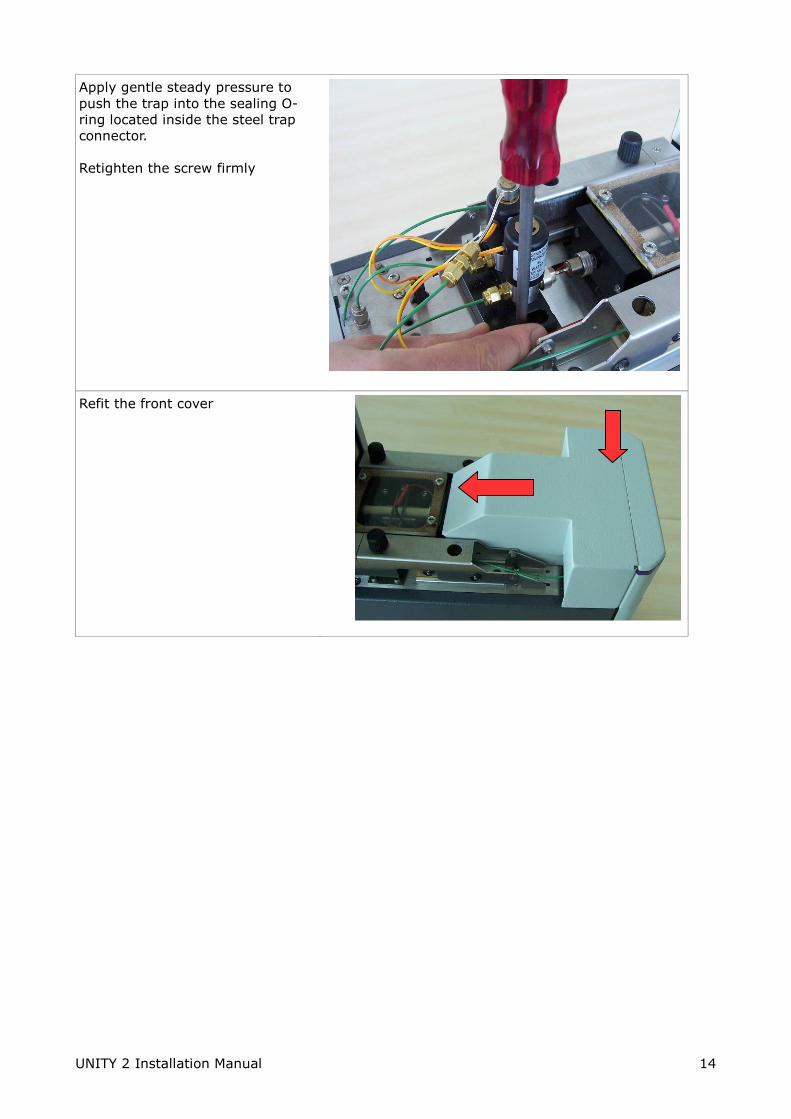
Apply gentle steady pressure to
push the trap into the sealing O-
ring located inside the steel trap
connector.
Retighten the screw firmly
Refit the front cover

UNITY 2 Installation Manual 15
2.4. Connections to UNITY 2
Connect the following:
1) Carrier gas line to the connector labeled
'Carrier Inlet'
2) Purge gas to the central connector labeled
'Purge Air In'
3) If using Electronic Carrier Control
refer to the UNITY 2 ECC manual
4) Power cable
5) UNITY 2 to GC cable SERUTD-5098 = AGILENT GC
SERUTD-5108 = THERMO GC
SERUTD-5116 = VARIAN GC
SERUTD-5095 = SHIMADZU / OTHER GC
6) UNITY 2 to PC cable (SERZ-0189)
Once carrier gas is supplied check for leaks
around the transfer line to UNITY 2 connection
with an electronic He leak detector.
55
66
33 22 11
44

UNITY 2 Installation Manual 16
2.5. Installing the software
Ensure that your PC meets all specifications presented in Section 1.1. and is operating under a
32-bit version of Windows™. It is advised to close down other applications on your PC while
loading UNITY 2 software.
Locate the UNITY 2 software CD supplied in the shipping kit. Insert the CD into the
appropriate compartment of the PC and follow the instructions on the screen. Alternatively,
open Windows Explorer (located under Start > Programs) and access the CD drive. Open the
UNITY 2 folder and scroll down the content list to Setup.exe. Selecting this option will initiate
installation of the software. Proceed as directed.
Once the UNITY 2 software has been loaded onto your PC you can access the program either
by double clicking the UNITY 2 icon placed on the desktop or from Start > Programs.
2.6. Running the software
Ensure that the gas supplies to the system - especially the dry air or nitrogen purge gas used
for UNITY 2 valve actuation and purging the cold trap box - are on.
Having checked the above, switch UNITY 2 on using the switch located on the back panel of
UNITY 2. Start the software as described in Section 2.5.
If communications between the PC and UNITY 2 are established successfully the
software will open.
If for some reason, communication is not established an ‘Instrument not Detected’ box
appears with a number of options, Cycle Power and retry? Run simulation? Select
options? and Exit?.
Choose Select options. This will take you to Ports tab of Options under the View menu.
Ensure that the correct PC comms port is selected.

UNITY 2 Installation Manual 17
Change the default comms port if necessary by clicking on the down arrow and then
clicking on the correct comms port in the list.
Close down UNITY 2 software, switch the power to UNITY 2 off, wait ten seconds and
then switch UNITY back on again.
Re-access the UNITY 2 program on the PC as described above.
2.7. GC interface logic
The GC interface logic options can be found under the ‘Ports’ tab. Ensure ‘Use Unity 2 with
Unity 1 harness’ is selected.
Check the correct operation of the GC ready signal. If the signal appears inverted i.e. software
reports GC not ready when GC is ready, then change the GC Ready (In) logic.

UNITY 2 Installation Manual 18
2.8. Installation Checklist
All ordered items present – if not please contact Markes International
Any shipping damage
All electrical fittings connected
All pneumatic fittings connected and leak checked
Instrument powered up & functioned correctly
Injections performed (blank and standard)