UNITED STATES NUCLEAR REGULATORY COMMISSION · UNITED STATES NUCLEAR REGULATORY COMMISSION REGION I...
24
UNITED STATES NUCLEAR REGULATORY COMMISSION REGION I 475 ALLENDALE ROAD KING OF PRUSSIA, PENNSYLVANIA 194061415 Docket No. 040-07123 JUL. 19 '996 License No. SUB-748 (Retired) United States -Department of Energy Office of EnvironmentalRestoration ATTN: W. Alexander Williams, Ph.D. EM-241 Cloverleaf Building 19901 Germantown Road Germantown, Maryland 20874-1290 SUBJECT: NL INDUSTRIES, ALBANY, NEW YORK Dear Dr. Williams: We are aware that DOE is responsible for the former National Lead Company (NL Industries) facility near Albany, New York. During a recent review of retired AEC License No. SUB-748, we found records which provide additional information concerning the use of source material at the facility. Copies of AEC documents which describe activities at that facility are enclosed. License No. SUB-00748 authorized possession of 38,000 pounds of uranium during the fabrication of a module replacement tank upper shield in 1964. Fabrication of all depleted uranium parts was conducted at the Albany, New York facility under New York State License No. 235-0482. We hope the material enclosed will assist you in your activities. If you have any questions, please contact Andrew J. Schwartz at (610) 337-5237 or me at (610) 337-5200. Sincerely, r~-- ._ ‘Cc- _- * ,/ _e_ .___ -. ; . 1 ” ,,’ '-Ronald R. Bellamy, Chief Decommissioning and Lab Branch Division of Nuclear Materials Safety Docket No. 040-07123 License No. SUB-748 (Retired) Enclosure(s): Documents from License No. SUB-748 file cc w/encl: State of New York
Transcript of UNITED STATES NUCLEAR REGULATORY COMMISSION · UNITED STATES NUCLEAR REGULATORY COMMISSION REGION I...

UNITED STATES NUCLEAR REGULATORY COMMISSION
REGION I 475 ALLENDALE ROAD
KING OF PRUSSIA, PENNSYLVANIA 194061415
Docket No. 040-07123 JUL. 19 '996 License No. SUB-748 (Retired)
United States -Department of Energy O ffice of EnvironmentalRestoration ATTN: W. Alexander Williams, Ph.D. EM-241 Cloverleaf Building 19901 Germantown Road Germantown, Maryland 20874-1290
SUBJECT: NL INDUSTRIES, ALBANY, NEW YORK
Dear Dr. Williams:
We are aware that DOE is responsible for the former National Lead Company (NL Industries) facility near Albany, New York. During a recent review of retired AEC License No. SUB-748, we found records which provide additional information concerning the use of source material at the facility. Copies of AEC documents which describe activities at that facility are enclosed.
License No. SUB-00748 authorized possession of 38,000 pounds of uranium during the fabrication of a module replacement tank upper shield in 1964. Fabrication of all depleted uranium parts was conducted at the Albany, New York facility under New York State License No. 235-0482.
We hope the material enclosed will assist you in your activities. If you have any questions, please contact Andrew J. Schwartz at (610) 337-5237 or me at (610) 337-5200.
Sincerely,
r~-- ._ ‘Cc- _- *
,/ _e_
.___ -. ; .
1 ” ,,’
'-Ronald R. Bellamy, Chief Decommissioning and Lab Branch Division of Nuclear Materials Safety
Docket No. 040-07123 License No. SUB-748 (Retired)
Enclosure(s): Documents from License No. SUB-748 file
cc w/encl: State of New York

NATIONAL LEAD COMPANY ?La;R Pile cOpt NUCLEAR METALS DIVISION - Industrial Department
1130 CENTRAL AVENUE, ALBANY 5. NEW YORK. IV S-4781
January 10, 19k4
ilr. E. Nussbaumer, Chief Source & Special HucXear Materials Branch 3ivision of Licensing 5 Xegulation y 5 .L . _c,EC :~EiSilLn&~~Oll, R r .b.
S;itbj ect : Application for Source License
Aeife-rences : 7 L. Purc;lase 3rder J-830-704
*\ - ' ‘. . .
L. \.
2. Procedure XLA-idA!f-2 "The Fabrication of the ;;odule Xeplacement Tank Upper Shield" (enclosed)
I. 2. General Dynamics-Electric Boat aivision Flan 2ti;~~72-039,
Revision B, "S31 ?_',efueling Module LIeplacement Tan;< Upper ShieldrT. (enclosed)
4. Sketch of Shipping Container, (enclosed)
Se were awarded c'ne Zeference (1) purchase Order .jrorn General Dynamics- Electric Eoaf 3Lvision, Grocon, Conn. 'I"r1.i s F.3. is for the purcha se 2: (1) one Xodille ReplacemenL Tan-k Upper Shield, 'co be Fabricated 2'01- lowing Isle lefcrence (2) Frocedure in accordance with the Reference (J) drawins.
=Oifiplet.e ?abrication 02 all depleted uranium rjecail liarts, ti;ill Ike Zone by t.ie >!ai;ional Lead Company, Nuclear Xeizals Zi-Jision, Albany, Ye\.- YorTc under I2.Y. S'cace License 23S-04S2. Zowevcr, the remainder rl)eI zzY.iP_ ;ia'0ricazlon will be Gone by .subcontTactors as I;ollows:
J ,ecl ya’bricadEion - Fe 3. Avery Corporation (T7 ‘;IL,i-‘-l 2 ;Iree’-
BilleTica, L >,lassacnuse::i:
Lead Fourins D -, : ' 1.
i .., ;. __ .., I _._.* "6 .A lwL$
p/o f&l z-r-ybMM-~-
- 2Iacional 'Lead Company Arlan~ic'Eranch 1.35;j S<a& L;t-eet %er t: i ,4mb 0 y , ifew Jersey
--__ “_ - - --.____ - - - . -

.
.
Xr . D . Nussbaumer, Chief -2- January 10, 1964
Alz-xou+ both or' these subcontractors posses;. "By Product" Licenses, niether has a Source Ilaterial license for legal possession 02 7Jraniwl-i. ';+e have enclosed copies of Xeferences (2) and (3) so t;lail CL -1e subcontractor conixct wit-z the depleted uranium may be throughly 3u1;l i qo'1 ..__^ -d. Zeferring fo tLe Ile,erence (2) i>i’O cedure Zabrica?ion (3 ': <e-ca-iis
i .
c, L.
.-.
._ .
i:. .
JO
; .
and suhassempblics, etc. will. be acconyl-ished as .:I.~~~ovJs :
.’ , ;al): ’ -i=:a-;ion o.,f all steel detail. pieces -in accor13ance ~;Ji.t82 ; ;-oCedUJ:e l.Td!-:'htJ- 2, ;,ec :Lon :. , 3ubsec~~ixls I, 11, III and 'L'?j , pa&es C. :l-lrous,l-, :- Zox;oraCi.on, Silleric:,
yj-i11 ;3 e a c c 0 mi,r, ]- L s :.le ij a '; T: . ,T . ,-':\ .J ,s y- y ;'lass.
:abrisaLion 02 all depleted uran'luix p-ieces in accordance \,l-i <z. ; ;cocedure >;LTa-~~>m~k-2, Sec<i,Dn ,L., subsection Tj, pas;P, 7, VJ-g]. be accoriIplisi.ied at National Lead Co., Xuclear Netals .-_ _. y~vi.is ion, Albany, 2.Y.
3tibasszmbly 0C steel pieces l-22 and l-34 in accordance \.yi,:-. pjrocej-~re, ~J?-;.~.~,~~.!-2, I;ection Jj, S7~'~ser,<ion 1, -pages C and 5 xi11 be accomylLs:~ed at P.F. Avery Corporatin, Billerica, Mass. This subassembly will then be shipped to :,:ntiorial I,zad '0. , .",lbnny , 1G.Y.
L,uoa s S C?iil’iFy 0 E .zIle deplete< -uraniujl.i .--in;s 20 i: le abo-\7c si;ecl
subo semnbly -in acco7i:i<ance 27-i cii i'-iOce:jeLl r'c _ .- - I'," -JqA'j- 2 ) Le:: CJll.1 3, ,u'us ec cion 11) Fazes 3 and IS, wLl.3. Oe accolilylisiled a.: iI.7.e
,<aLional Lead 30. , i?l'oany j 1T.Y. 2;. ii 2 'c subasseinbiy Vi11 .:OTILZin approximately >G,330 lbs. or depleted -uranium mezal. AiCer compietion, I:fIis sllbas3,11 '-llDl.y will Se Lxi'vcker.1 f--.-) p. F. )-very :,q:9raSi on, 3i.llei:ica, ilass.
ju:3a,,,Li J , c c s-1:- I\? 32: ;iiecy :- 31 it3 L:le aYLa,-\ie s:,;j,a-2sa~:njl~j .:3-L d c? ~2 c ,I a~ ;:I a n r, e :.I_ : -' ,..- \"LC ? __ L,J';/'(.t~, ;,3 '7-i ,A -,/+*ri-2, _.A.- ,Jec.~i,ytl 2, ~uijse~:‘.:~-cJ~, IPI, paLe l-:3 w:-ll. ;;,z ac.-,.J,ii.;.el<ss .le,j 2:: ". ?'. :",ve:::v , ; 1 : -= __I _. 2 .'. 3:-! '- -. .*- -11 e ., - -Y -f- : _ a --- > ;.:a 8 CT - . -Y i ;.. E s1.1 .)a s s CL;::> I y '.{ a' . ; .'- I !. I13 i; 3 c\ 5 J;-,,- 2 _ ; ,, , -_I7 8. c. L A : 3 ::a :-.iona]- ',-a I L.2. , 1: cr i ,q: ;;;;J; ) ,I, 2.
-7 L.&sec~f,;,,~n ;‘. , ~T<,~~ T-1, an: y-2 ;'i;1.,. 1: , >;:'-Jje ;..;_1 ,-c:c:;yJyLi-: .,.-;..- -> r c. at zile :4a{Lional Lea< Co. , ?erc:!i k!!;nL7o'j, E.J. .! _L_ L ' -I'-er C 0 i A'-, 1 C 2 I c) 11 ) LI;E unit wLl1 be zeixxned z ?. A:. i',very Cory.,,Silleryca, !;ass.
- - - ~C - . . . _

1*:-r . 3. Nussbaumer, ChieT -3- January 13, 1964
7. P inal work in accordance wi.t;I‘ Procedure IL~-WA!-I-~, Section B, Subsection V, pages E-and 14, will be accomplisiled at P. P. Avery, Corporation, Eillerica, Liass.
Summarizing the above, contract with exposed
our subcontractors will :lave only the i'ollotirinz uranium metal:
P a. ixJ&.;l-ler subcontractor will do any fabrication rcork on tile uranium metal i.tseljY.
5. I?. 7. Avery Zorp,, Dillerica, ;lass will receive ?he assembly with only the 3.3. and top of the uranium exposed, and will immediately start assembly of the outer steel shell to the unit, so that only the top ol the urani_un assembly will be < exposed. (See Faragraph 5, above).
r J. Yational Lead Co., Perth Amboy, ;<.J. only tki.i6 izop 02 the uranium exposed,
will receive an assembly wit
fill, and will immediately lead
and t;len no part of the uranium metal will be exposed. (See paragraph 5, above).
D. This is a one(l) assembly unit (1) one time shipment.
Naximum exposure to radiation is estimated as follows:
P -. F. Avery Corpor&on, Billerica, 3 weeks
Xass (outer steel shell not in plan
maximum Gamma radiation rate (12" irom outside surface) 2.0 MI< per Hr.
maximum Beta-Gamma radiation rate (12-I i-rem outside surface) 20.9 IfIX per Hr.
National Lead Co., Ferth Amboy, N.J. (outer steel shell in place) 1 week maximum gamma radiation rate (12' from outside surface)
. 7 Mr per 11-r. maximum Beta-Gamma radia.tion rate (12" from outside sur:ace)
7.0 I$? per 9r.
The above radiation levels were estimated by u&g the maximum readings obtained with a geiger Survey -Meter in a preliminary cheek of a single

Mr. D. Nussbaumer, Chief -4- January 10, 1964
uranium ring and calculating the maximum raitos for the assembly of all rings, without the steel outer shell in place. Estimation of radiation rates with the outer steel shell in place were made using l/2-value thickness tables. Actual readings of the whole assembly cannot,of course, be made until the unit is completed and ready for shipment.
A National Lead Representative will be in attendence as long as there is exposed uranium present, and he will ensure that health and safety procedures are followed as outlined in the Health and Safety Manual.
Shipment of the assemblies containing the depleted uranium will be made under the following conditions:
A. Exclusive carrier
B. All shippin, 0 will be done in a vertical position and the shipping container (see reference 4) shall consist of a 73" dia. x 3 3/4" thk. base plate (A) with a positioning ring (B) which locates in the ID of the base ring of the shield assembly (C) to prevent relative motion between the two pieces. An "Xi' frame structure (D) with a top plate (E) and positioning ring (F) is placed atop the shield assembly and locate in the I.D. of the inner steel shell of the shield assembly to prevent relative motion. This top plate is chain lagged (G) to the bottom plate to to form an integral structure. The unit is lagged to the shipping carrier from points (H) on the "Xi frame at the top. During the shipment of the shield, before the outer s steel assembly is in place, l/4" plywood will be wrapped and fastened around the exposed uranium. Preliminary radiation checks on one uranium ring with the wood shielding in place, were made using a Geiger Survey Meter. From these, readings, calculations for total radiation rates for the assembly of all rings were made, and maximum radiation rates are estimated for the entire assembly as follows:
12" from outer surface (Outer Steel Shell not in place - l/4,' plywood cover in place) Gamma radiation rate - 1.10 MR per Hr. Beta-Gamma radiation rate - 3,5 MR per Hr. 4
c. The shipment will be made using Red label Class D, Group I poi@Qn tags and Radioactive Material placards, in accordance
Mr. D. Nussbaumer, Chief -5- January 10, 1964
with the Handbook of Federal Regulations Applying to Transportation of Radioactive Materials (g) l
, paragraphs 73.391 and 73.392 (f) and 73.393 WC, would appreciate immediate action in that our present
schedule requires shfpment next week of the uranium-steel assembly to Perth Amboy, N.J.
WAH/CJM/bam enc.
-_- _. ..__

,c . . iT 1 +,
33 oa :IhgI pe.haTM~
“.. .” __I--
UQ~~SZ~~XO~ kahv "d "d
XPapdmQ=)
CMIHHS Uddfl XNVJ, ZN3HZWId33 TIMHM 3KT, d0 NOZ;tV31[‘)1$Vd 3H;L
m’L --Qrs ---yY!q
wu\i F y-’ ” ‘- L-.... ,.
9T 30 I a2'ed Z-HVM-VTN
c
\
.- .- “F--’ - -. -1 4
N-n . , -.
1 NLA-WAH-2 . . I Page 2 of 16
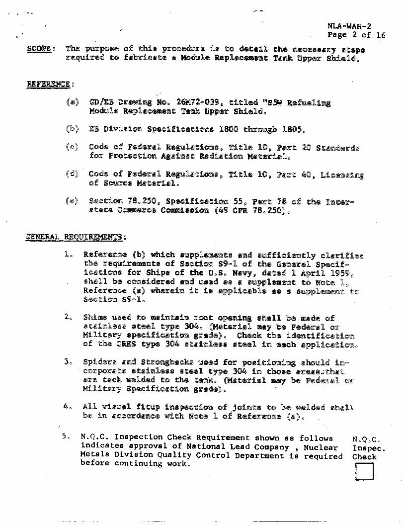
SCOPE 2 y.% E jJlluz.rrpQe of ahfe pmxwhnre t.Q a:0 dea6illu ah-42 uneQ@QQ&?lq QaqpQ ~~~~i.~p~d a0 fd3dk~a~ Q bb31~R~ Replacea mHn8s. Bpppe~~- sMdd,
m /m DIPOti~ ioo 2W2-839 o aflahd W iw ~~2fdni~ MQhII@ Rcqzdhcmlrnt lL%l& upper Su~nd,
m t D~V~A~OEI sg~~fdf~63afons B800 aThm m @ 1805, Code of Fed@ran Re@nnalaimQ~ 7ftaIIe 10, Para 20 sa~dht=dk f07f m=oa63eaion Agdh8a mdit~afl~t~ madhn. cd~~ 0f F~CSXIR ibgpn~a:%0~8, 0% so~rece t4aa~2dLdl.
7ria:Be %O, m ra 450, IL~CXXXI~~
ssceaibm 782XD, sgtbuE%c~aim 55, m ra 78 ~8 the Hnaer- Baaas c-res c~~oim (49 tmu 78,250),
no bft3~63bce Qbj %sfri.~h 8a;sppn~~ab9 and ~uffidhang dhd.fm ahe ~peapd.r~nt~ 43f secaim s9-n 0% eb eemem specff- %Cda%0tm for ship8 0f tb U,S, ~3eov, bad B April m m , tddtn BS CCM%~MP~ tit~d WCI~ k98 671 f3ugplmsna a0 hbaa n, RC%S~~~C~ @ I) 0-8hereim fa FQ ~ppnicdbns ak33 43 8uppR~aa a0 ss~tfo~ 894,
40 Ann dhd, fimp i.nssgce?eaim ~f,jdha~ to be ~ddk2d 8ltndh b62 ~XI ~CXX~~HNE tiah Noat3 n 0f m fsrpace @ I,
50 N.Q.C. Inspection Check Requirem ent shown as follows indicates approval of National Lead Com pany , Nuclear
N,QoC, Inspec.
M etals Division Quality Control Departm ent is required Check before continui.ng work.
l-l

. . . . -.
t&A-WAH-2 . . Page 3 of 16
c
6. General Dynamics/Electric Boat Division approval shall be obtained prior to any repair welding as a result of defects located when radiographing to Note 4 of Kefer- ence (a).
7. At the completion oi each circumferential butt weld, check dimensional tolerances with centerline for conformance to the-dimensional requirements .of Reference (a).
a. Established standards, for protection against radiation hazards must be followed in accordance with References (c) and (d) and all state and local regulations governing the handling of Source and Special Nuclear %teriaLs.
9. Any shipping container used for transporting the Finished Module Replacement Tank Upper Shield or any subassembly thereof which contains uranium shall be conspicuously and legibly impressed with the legend "CAUTION - i lAD’I’OAC;ILVE - S;IIELDING - URANIUM” and shall meet the specifications of reference (e).
PROCEDURE:
SECTION A, lhe Fabrication of Subsections l-SL, l-S2, l-S3, l-S4 and 3 of the Module Replacement Tank Upper Shield.
I. The Fabrication of Piece No. l-S2 of the Module Replacement' Upper Shield
1. Using stainless plate QQ-S-766 Class 30A Condition A (98-718" x 146-3/4" x l/Z"), machine a double beveled weld groove on the 103-l/4" edges in accordance with Detail 10-A of Reference (a). In calculation of proper length, allow for a minimum of l/4" of extra material on all surfaces to be machined.
2. Roll piece l-S2 to form the vertical double grooved butt joint at the 103-l/4" edge as ind,icated in Detail 10-A of Reference (a).
3. Using shims, maintain the proper root opening in the ver- tical double grooved butt joint formed in Step 2 above as required in Detail 10-A of Reference (a).

. .
NLA-WAH-2 Page 4 of 16
4. Position rigid spiders and strongbacks as necessary on the inside and outside diameter to ensure conformance to the tolerances required in Reference (a), Spiders and strongbacks will be designed so as not to restrict, weld accessibility. Tack welding shall be in accordance with General N&e 1 of Reference (a). Tack welds shall N.Q.C. be free of cracks when visually inspected. Verify Inspec. acceptability regarding dimensions, fitup and weld pre- Check paration. -Correct and re-inspect if necessary.
5. The welding of the vertical double grooved butt in cl
plate l-S2 shall be in accordance with the following re- quirements.
A. Base Material Preparation - The base material prior to welding shall be cleaned in accordance with Note 5 of Reference (a) using aluminum oxide grinding wheels, silicon carbide burrs or stainless steel wire brushes which have been used only on stainless steel. Visual inspection of the prepared joint dimensions shall be in accordance with Reference (a).
B, Welding - Welding shall be performed in accordance with Notes 1, 3 and 12 of Reference (a) and deposited according to the welding sequence outlined in Figure 1.
C. Non-Destructive Testing -
(1) Dye Penetrant - Dye penetrant examination wihl.be performed in accordance with Note 2 of Reference (a) e Prior to final dye penetrant examination, the weld shall be contoured to a finish of 125 RMS or better in accordance with General Note 13 of Reference (a).
(2) Radiography - Radiography shall be performed in accordance with General Note 4 of Referenc,e (a), Radiographic techniques shall be based on the finished machined weldment. All welds to be radiographed shall have .a surface finish equal to or better than 125 RMS in accordance with General Note 13 of Reference (a).

NLA-WAH-2 Page 5 of 16
The Fabrication of Piece No. Tank Upper Shield
l-S1 of the Module Replacement
1.
2,
3.
4.
5,
Using stainless plate w-S-766 Class 304 Condition A ’ (98-7/8" x 18379/16" x l"), machine a double bevel groove on the 98..7/8" edges of the plate in accordance with the requirements of Detail 10-A of Reference (a). In cal- culation of-proper length, allow for a minimum of l/4" of extra material on all surfaces to be machined.
Roll plate l-S1 to form the vertical double grooved butt joint of the 9807/8" edge as indicated in detail 10-A of Reference (8).
Using shims, maintain the proper root opening in the vertical double grooved butt joint formed in Step 2 above as re- quired in Detail 10-A of Reference (a),
Position rigid spiders and strongbacks a8 necessary on the inside and outside diameter to ensure conformance'to the tolerances required in Reference (a). Spiders and strong- backs will be designed so as not to restrict weld access- ibility. Tack welding shall be in accordance with General Note 1 of Reference (8). Tack weld8 shall be free of cracks when visually inspected. regarding dimensions,
Verify acceptability fitup and weld preparation. Correct
and re-inspect if necesrsary N,OoCo
The welding of plate l-S1 vertical double grooved butt .Inspee. Check
shall be in accordance with the requirement8 listed below,
A, Base Metal Preparation - cl
Same a8 described for the fabrication of piece No. l-S2, paragraph 5A,
B. Welding - Welding shall be performed in accordance with Note8 1, 3 and 12 of Reference (a) and deposited accord- ing to the welding sequence outlined in Figure 1.
C, Non-Destructive Testing -
(1) Dye Penetrant - Dye Penetrant testing shall be performed in accordance with the 8ame requirements as indicated in Subsection I, Step 5C,
(2) Radiography - Radiography shall be performed in accordance with the Same requirements as indicated in Subsection I, Step 5C,
_ - .l-l_l ”

- %
. .
*
, . NL.A-WAH-2 Page 6 of 16
III,
IV.
The Fabrication of Piece No. l-S4 of the Module Replacement Tank Upper Shield
10
2,
3.
Using stainless steel plate QQ-S-766 Class 304 Condition A or a atainless~steel forging QQ-S-763 Class 304 Condition A (59.3/4" O.D. x 46-l/4" I.D. x 2-l/4"), machine all surfaces a8 specified in Step 2 below in accordance with Detail 9-A and all other specific detail dimension8 of Reference (a). In calculations of proper stock size, allow for a minimum of l/4" of extra material on all surfaces to be machined.
Rough machine all surfaces. Finish machLne the top and bottom surface8 to obtain' the 2-l/4" in accordance with Reference (a) but do not finish machine 57-l/2” O.D, x l/4" step strewn in thebottom surface. Finish machine the 57-l/8" 0,D. x 54-l/8" I,D, x l/2" Dp. groove in the top surface a8 shown in Reference (a)o Finish machine the circumferential single bevels in accordance with Detail 9-A, Reference (a). The remainder of the finish machining operations will be performed after subassembly.
N,c,C, Verify acceptability regarding dimensions and surface finishes in accordance with Reference (a),
Inspac, Check
l-l The Fabrication of Piece No. Tank Upper Shield
l-S3 of the Module Replacement
lo Using stainless steel plate m-S-766 Class 304 Condition A (60-l/4” 0,D. x 47-l/4" I.D. x 2-3/8”) machine all surfaces as specified in Step 2 below in accordance with Detail 9-A and all other specific detail dimensions of Reference (a), In calculation of proper stock size, allow for a minimum of l/4” of extra material on all surface8 to be machined.
2, Rough machine all surfaces. Finish machine the bottom surface in accordance with the dimensions of Reference (a). Finish machine the circumferential single bevels in accord- ance with Detail 9-A' Reference (a), The remainder'of the finish machining operation8 will be performed after subassembly.
3. N,c.Co
Verify acceptability regarding dimensions and surface finished in accordance with Reference (a).
Inspec. $heck
I
..-- . _

NLA-WAH-2 Page 7 of 16
The Fabricatboa of PBece.s No, 3 of ths ModuBe Re~bacemaat Tank Upper Shhsbd
using uranium metal per SSW-MRT-2, cast a maximum of (9) uranium rings C57-I/&'@ O.Co x 47=5/e” P-D, x X") in accord=
6 and Detail 4-A
acceptability od each c8
3. Ncn-Destructive Testing
h, Viauallly check s'ach casting fsr primary and secondary Pipe P surface porosity, cold shutts, Lags and seems, This in$pectiom ohalJL be performed by a N <> C .> C o metalBurgbst wh$ is versed in urenium casting InspEc? technoBdgy I and is therefore qukpiified to Check accept or rej:4Ft the caotbng, .I
I 4, Rough arnd finish '&chine bottqm No0 L in
accordance with t&e dimensions of 4-A and the en- Isrg,ed view the interface this ring and Piece h-S4 in Reference '",'.
5. Rough and finish i-!
A, Verify accept lity of urani " rings regarding NoQ,Co dbmen8ions in cordancc with afcrence. (ajo hmpes 1
; ! Ch@!ck go Rough and finish iaine top ring Q accordance with 1
the dimemefons ot tail 4-A and p other details cl rcHetive tci t&e td ium-Bead inter&e as given in Reference (@]. :I
1, il ,I! 1. ! 1,
P, Verify scceptasdkity of top regarding dimensims in accordance 'hith Reference No C o C..
:' I / ,I mspec D
Ii Check
III
--._I_ I- ._ -. --
c -
NL.A-WAH-2 Page 8 of 10
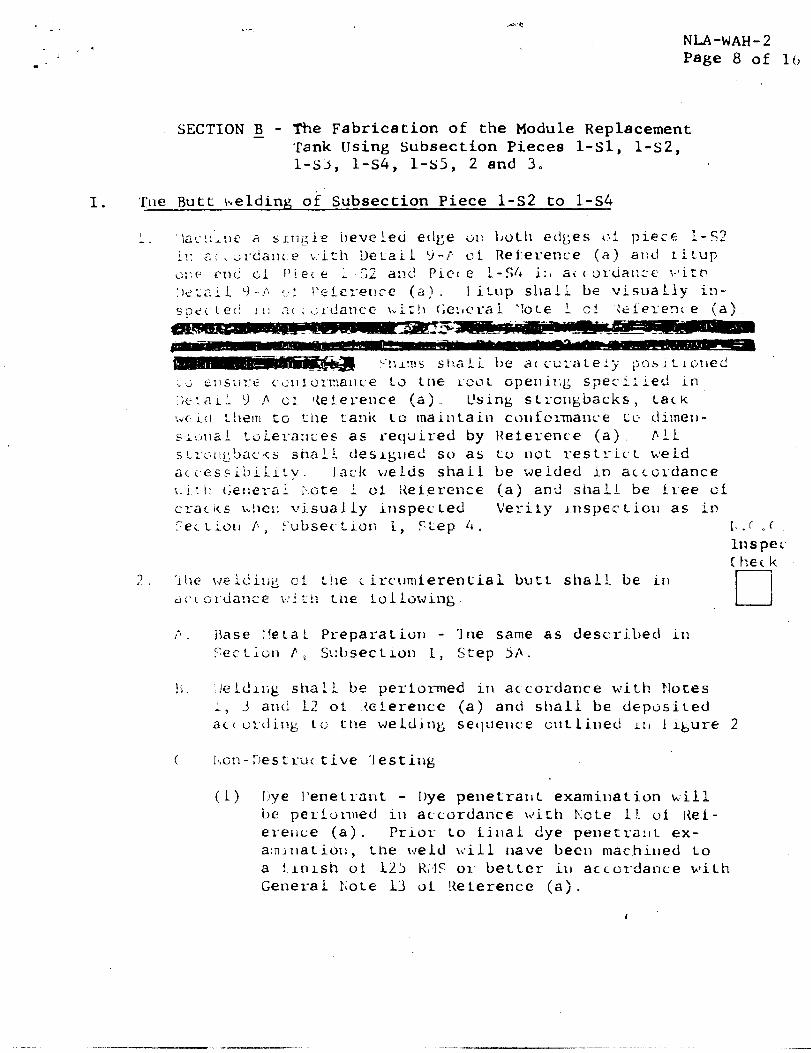
SECTION fl - The Fabrication of the Module Replacement 'rank IJsing Subsect ion Pieces 1.~1, 1.~2, l-s-3, l-S4, 1-~5, 2 and 3.
I. 'Ihe Butt iwelding oi Subsect ion Piece l-s2 to 1.~4
I . . laL-!:l:le a SiKTi_:ie ilevcieti fZtl&;e ~21: ljcitll etibes c:? piece L-52
i!: c’.. . srda1lL.e \:ith Del-ail 9-p oF Rei-erence (A) alld r. i~up Gl:e f?tli Cl I'ier c' L 52 a:ld PiCc e ?-SLb i:, a< (tJy6ja[;:e ;.:it:t? :,e::ai L +I-..I: r..' If‘eiere~!ce (a). I iLt:p sl laL? be visually in- spei~l.c:i !I: 2~ ; ~;r~~!ancc \,it!~ C;e:,craL ‘:ote L cF tefeye3r e (a)
“!:L!!lS staaLL be a( cu;‘ate?y ;josi:lcirlec!
i ; .o~,s(;y~ 1 ci:~l:or-mitlce to tne i‘ooL opeliil;g spe:i:ied in :;e:aii. 'j .!I cl Iteier-ence (a) L’sing stmQtxicks, Lack :dC i.:l L!ltZl?i fG I ;1182 tank to maintain confcrmanc*e tc dimerl- SL\rllai toLerar~ces as required by Reierence (a) fill s crc~I!,~?lac!c(s 2 shali deslg;llec! so as to not restrict \%BeLd acc~Gs5ibiii:y. Iark \ ,JeLdS shai.1 be weLded in arcordance 1. i C 11 (&:lt?l-Zi i r..GtP i at t<eLerence (a) and shajLL be tl-ee ~1 crac its h!!~c~; visuaiiy inspected Verily lnspc;cLioiI as in ,?ec. L ion ii , i‘ulbsec Lion 1, Ciep 4. I\ .: <, (
Inspec c hec k
3 ‘. . 'i \ae W E ii! ilig oi :Ile ~irc~3~erenLiai butt shal!. be irl dcc o~~dans:e ~-i;!l Ltre IolLowing:.
I? . i \ase :!eta h Preparation - Ine same as described in Fectiori F i: Sl:l)sectLon 1, Step 5A.
1; , !eLd11;g shall be perFormed in accordance with Notes i, 3 and L2 OF Aeterence (a) and sllall be depOsited act or-ding tc Ctae weLdinl; seclueuce c\ltbilied L:) 1 lbure 2
( Ihan-Destruc tive 'lesting
(1) liye l’enetrnnt - I)ye penetraxlt examiilation will be perfolmed ill accordance wiCh b:ote l!. vi Iief- erence (a). Prior to tillal dye penet:ra:lt ex- a:nil~a t i.01) , the weld fii.11 have been machined to a ilnlsh ot l-21, K;,lS 01. better i.1) act urdance with General P;ote 13 oi !<elerence (a),

. r’
‘
, J . .
N L A - W A H - 2 P a g e 9 o f I.6
3 . F in ish m a c h i n e th e .a b m r e b u t4 w @ ? L d a n d th e 3 0 " bev@ Hs a n d tb a 4 6 e 2 5 0 " B .D, ( on P iece I.-S 4 1 in acco rda rnce with th e d imens ions a n d fin ieh r equ i r emen ts o f R e fe rence (a ]. Pe r - fo r m dye p a n e tram t tes t o f b u tt joint a fte r mach in ing as dcse r ibed a b o v e in S a c a i o n B , S u b s e c tio n I> S te p 2 ~ .
4 , Ve r i fy accep tabi l i ty in r ega rd to d imens ions in N O O ,@ , a rGo rds l fE e -wick R e fe rence Q e ) 0 Inspec D
C :hesk
'II< < l b -S2‘ IL -s4
n
i” A s s e m b h e b o tto m u r a n i u m r ing N o 0 B to % b a s o e m b Iy I-S Z p E - S 4 8 8 f3 ,HksW 6 ,
A ” P r e h e a t th e b o tto m u r a n i u m r ing N o , B [P iecs N o 0 3 1 T V a te m p e r a tu re wh ich p roduces a m inim u m o f O .IO ()" :.% :m a l expans ion o n th e I.D . (app rox . 3 0 0 " IF;
B " Us ing d special . r ing l i ft ing fixture, r e m o v e u r a n i u m ‘ r ing N o , 1 from th e fu rnace a n d check th e B O D O cxpcmn- a i m with a spec ia l " G Q - N o G o '~ g a g e . Pos i tio n ths u r a n i u m r ing ove r th e S u b a s s e m b l y W e B d m e n t (P ieces I-S 2 , E -S4 ) a n d ca r sBuU.y B o w e r t;hc r i ng a r o u n d S u b - sect ion P iacs L - S 2 a n d sset aga ins t S u b s e c tio n P iece l -s4 a 0 fo r m the shr ink fit o n th e 54 -1 /lY D ia , a t th e u ran ium-s tee l inter face in a c ~ o r d e n e c with R e fcaence (a ) 0
co B w s p e c t th e subassemb ly ts veri fy p rope r fit in N " O " C , secs rdmce with R e fe rence (a ], Inspec L
Check 2 " A ssemb le each sf th e r e m a i n L n g u ran iu :r, r in;gs N o , 2
tE n r o u g h Ns o ( S e e Gene ra l i b k ~ te 6 , R e f@ reace (a)]) to S u b a s s e m b l y B - S % , Zk4 as fs!.kows,
A , P r e h e a t 8 ~ in S u b s e c tio n 1 1 , S te p B A a b o v e ,
B . Us ing a spec ia l r ing B ikt ing fixture, r emov6z th e to r m i u m r ing frm th e fu n r m c e W - Id check tins B O D ” sxpans ion with a spec ia l “G O - N O G Q ” g e g a , Pos i t i ion th e u r a n i u m r ing ove r th e S u b a s s a e m b l y W e B d m e a n t (P ieces B - S 2 , I-S 4 ) a u n d ca re ful ly B o w e r tkne r ing a r o u n d S u b a e c tisrn P iece l-S 2
- - I ,x-- - - - . , - .
, . - - -

NL.A-WAH-2 Page 10 of 16
and seat against the previous uranium ring so assembled to form the shrink fit on the 54.625" Dia. x l/2" step interface between the adjacent uranium rings in accord- and with Detail 4-A, Reference (a).
CO Inspect the subassembly of each ring using 0.005" .Go and 0~.016"' No Go feeler gages to check the gap
between the 54.625" Dia. and the O.D. at the step interface between the rings, and verify acceptance NoCoC, in accordance with Detail 4-A, Reference (a) lnspec,
Check
III. The Butt Welding of Subsection l-S1 to the Subassembly El l-s2, l-S4, 3
1. Machine a single beveled edge on both edges of Piece l-S1 in accordance with Detail 9-A of Reference (a) and position Piece l-S1 on the Subassembly l-S2, l-S4, 3 in accordance with Reference (a). Fitup one end of Piece l-S1 and Piece l-S4 in accordance with Detail 9-A, Reference (a), Fitup shall be visually inspected in accordance with General Note 1 of Reference (a). Shims shall be accurately positioned to ensure conformance to the root openin&. specified in Detail 9-A of Reference (a). Adequate weld- ment and jigging shall be used to insure conformance to dimensional tolerances as specified in Reference (a), Tack welds shall be welded in accordance with General Note 1 of Reference (a) and shall be free of cracks when visually inspected. Verify Inspection as in Section A, N.Q.C/ Subsection I, Step 4.Note:During fitup, offset the vert- Inspec. ical seam on Piece 1-mOoor more from the vertical Check seam on Piece l-S2 in accordance with Reference (a).
2. The welding of the circumferential butt shall be in accordance with the following.
A. Base Metal Preparation - The same as described .in Section A, Subsection I, Step 5A,
B, Welding shall be performed in accordance with Notes 1, 3 and 12 of Reference (a) and shall be deposited according to the welding sequence outlined in F'igure 2<
C. Non-Destructive Testing - Dye penetrant examination will be performed in accordance with Nate 11 of Reference (a). I
--_---

NLA-WAH-2 Page :I of 16
IV. The Pouring of I&ad (Piece Na, h-SS) kwto the !%.ebeasemIzLy af Tieces I-SL, B-S2, B-Z%, 3
1 c Ueing oskunm T-9-56, @Bass I, ceuPk the cfrcwmfercn,:iai- gaps betwesn Subaactio~ Piece T-Sk and. the rep vxaniur ring Piece Naa2 3 and be:twefcn Subsection Piece L-ST ad the t:op uranium ring Plcczg No. 2, in Lcco r&!n.cg $4 .;, (C'rl. Reference (a]..
? La Preparali ian fQ!f L.z$id pmurlag sh&Li: be as, f2L1aws:
EC ALL som~ammt w~~~chm’lts. iare ccc be fu~~~&~& c>~:jbp,b~~.~ i - Y: fbrice~cd WLCh SiLL i.nr;erma!ll 9 itJ~~&ces. cQmp;lcrr:e!,y f:;,er ef walki sphxer and srihcr ftc3 %i.. hgz K@l ‘5 ;t e z .,
c.: Ali a%nicHd we~dmsnts are cc be placed in Gt-nei~ p-c,>~: positian for pouring, Ievened, sbnd breleed t;Q! ma:Fntte-,:r 2, IIetvel s”,titu,de r.-nrQughQuc r’kile py!JY
D (1 WeLdm&?rl’; ins;gccLion s?nsJ.ka be as, BaLao-ws
(2) Dimensiawa.L ehecksz of e.lL cxifissih wei~&nco~'t dimcrraaions asinn be lmLhd~% in accoxda.n.ce w:. eiT> Re%ere.mice (@I"
7 -’ /. Lead pmrilrpg ymcledurce a%sLL 1! be &S fcS.lows
A. Using n-~-J L-871 cr.&& 2 lce&l;b, hear fl(C a .ll:iy;ypJm ,,>f 750° 8Ttd .ZI ~~XiE&,J~j Qf 9,jjQs> i dl$$pendin,g Q(r;’ c’ne sia.E? and type Qf wekh?R2~a being gw!m!&d (, Exa.st baa+! pathY-= inlg tcZepE2TCi3TCres “dihl be de:erminsd 72,y ~~~‘m~!rib~fdc~:‘t.i:r~-~~,

L -
. .
I -
n<
. . . . /rs,
1 ,' NM-WAH-2 Page 12 af 16
department prior to each pour based on current ' ambieat temperature66 Such cemperarures will be
maintainad and recorded tshroughaut the pouring * opeaacioat, i The steel weldments are to be preheated by means of gas torcbbes, heating rings, .cr within a heaced en- slssur&~r by a combinatisn of .zlL such mebkxds In au~sk!~ a mamer &EF EI uriifar;r. shell CEmperatk.zre cf 4OWF Yin LI - L5O*F Mgx is cb,ta ined 'I his min ixm temp,erafmre is to be maF17taFrle2 bbsE)VC the scLibFC= ication bevel of the lead 0~ tcrches thrsughl;x.t ~hce entire shrink.-cssling cqm-a~';a-! {,3-D) imci cQG;trOfli.~e~~. by magnetic temgeraewre Lndrcs~ors or by tremp-s:bik applications,
C” The sbhlia of && ucic. :cLe cc be csmp:ie’reiy fihlee by B cona;inu@ur paur with Zhse folhowiwg exception,
(1) The priory cos;ta%ner with concentrisity spacers proper2.y focaced viHL be poured con- tinuously tu a point sligh~%y above closure phete shsukder. The shrink-cooling ~p,cratLsa, (Step D) will. be started and coca~inued ipclci.1 the pour has been s~kidlfied
D I> 'Ilx Lead-fihBed,lunits are cc be shrink-cooled by means ail sir efmveeti~n pcsmicting t,he hisaC C;o e%mpe thrDRJgkl! ehs Lower surfases. whiLe hsat ia Dsmtinwou&Ly apphied t<a a;he upper surfaces, Ihis wiih pravide a reservoir of molten lead CC. feed the res~uLlta~-~ft sc;Lid- LCieaci6n shrink reacricm,. 33aEL amounts uf additiowa;b liead are tcr be hand-ladled into the shle31 8': frequent inrervehs tcx mainrain a. fully fiLLed exxliCion, ThS s~LPdifiea3ti.ax-d bevel is tc Se erhec'ked aE freqwewt in- rervabs by mcms of a virs ~rcbe i3 or&r thwi: .tbz 9pp%it21tf~~ SC, heap ~85~ be ~&USCJE~ t~r~~2thy at3 wabntaix~ the sbsve mmn:rFm& moLcern lead se~arvoir, Tltilcoe QperaciQns &arfE ta bs eaatiww@d untill Km furPt'hcr sohEdLfi,caaiow &xinK(se~.e 24s ehizOuma@Tredi.

.‘* . ‘.a( i--+-F, w--q
- ,* , . - hT& -WA&( 0 2 * . . -*:
1 : Fage k? sr.f L6
I 8
4 0 D%wasiona% iw6pec~iow; af2azc Ls&i p&?g-~&~ G,‘;.._F, L:. 2-z i&g f=il%cm?s;
d I, Afr;eL- !5?Lg kesa.C fkl&&$c 9&I-,: L :r-(< !f,,i.--:s “,,; +;“ I,,,> :
tegp@racd& b &3 &be& %$hl ‘;;E &ja .->,,Z ‘-s_,, :.,7, - +::-;,. &-. I_ ~.qrrJ\P
d&@ngiaaa>A y.&rjR:efsn.g E:;tg.: i-i$,jql; -:: 3,, - --. 1 ;i- - y -.b - i- ..legd p-4ritn.g -v+y*$y~-y:w: ~ 7’ .“‘.r “y,‘-“. ; _ _ 5:: ;, 1,”
&+r,.zQ&,g&~* $9 z$: ~>,~~~~&oJ~,” a
i. .
- ),. 0 .*
-... ,, ._ .: .-..6
I:--6
: I I ‘w .., 2 I- - / 3. f& 2;. -. - ; .a .s -F,:j‘r, ;. ,& ;:gf;- * . . -*.-,-- _ - ,’ , . , f* =;q..+;-; $7;” .;,< ,(<‘-r:; I ,_, L“c.,T ,, : _~ .. _ _ ,h,,... _ ‘Y c r. . . , ,
.
r
.>- 5$hc.r,\.I.>..;:,
” >;7 . . :. ,, :. d-
. .~ j--,
!
. / ; &;-m-s+
’
‘.
. F F w.--. -s

.--- 7.
-. 9 .. ,...II ’ -.
--.. _I.. .
r i,:;.. .,, L .‘$.... 2’ ;.y .,‘A
..,, . . : ;
..-a., ;; _ I.:
L . .
: I
.
..-_- ,‘- c _ . ‘L. -7. z.T “. ,,: -L ,., <. - -$rmer?3
. . c .-*.:. .- _, , . - _ . “-,>.!. : T*.!k*y’e. ‘& .
-L : : .= y ‘1 -. - - _ .‘ .+ _ .:: - _ T’ . . j. .- _ -
p.:: ,. : :,: z , + “7 ; \
MArWlbjlp2 ., R&e .BG.$sf 16 ,,
’ .,, . j:
\: ’ ;; ;”

VERTICAL BUTT WELDING SEPUENCE FOR PIECES l-S1 Ah9 l-S2
i-7 ‘1.) i
1 ‘S>,., . 4
.- :-
3 i -.
. . . .
.
‘*I.
:a.. ’ “.
*’
.A.
I ? ;: c ;; :,,zT,>s SHOiJLL: i?E P. FlTi<IN’d>~ 01 2’: TI.2 LEKGYI
!X.?I??:G FTECES l-il PXD l-52 - ‘i’l!E rJE?CCT’Y OF !GELI‘, ??E’i’AL ON ‘IPE F[.iTS?’ SIDE SXb.LL BE LiPIZ’i ED ‘J Cl 1/16” !J?:DEiiF’Ll.?Sif A’I WHTGH '; '.>;E 1;A(;;(C,~lJjI~;G ;.:I il, p,E S'rj,R'J'EJ,.
*n",
FIG. 1s
--

1. i.
t f
, -;,-ELijl;iG SECiUE!KZ 10 ZZ L:SED FOR
ALL CTRClPITEX5~~-i-Zb.L BlJ ’I’i’ KELDS
i- I. ;A
.’
,A
2
1 % O F F SET
1-J 7 ‘*;
NLA-W AH- 2 .Page 16 of 16
SUCCEED - AYERS S5*
i:"*-F;j; _ i;T,; y 1:: 1 i ‘:(:-J-E- 1, L) .";.-y: ; ,'y;.; . . ;;:;: ..'$j,Z Jz' :E
7 i. ?:!:;TE(‘.. :<;; 1c, \.' h ,.'Y' .i* .,&A KS; " ; I:;',,, ,, ;: .Y' . . . ., / I:: ,>;E,!): I;<; >,s.- TJr;r:f;E .

DLRrDFI! 40.7123
.wm$., . i-c ‘,#
L :’ 1964
National Lead Company Nuclear Metals Divleio~ Industrial Department 1138 Central Avenue Albany 5, New York
Attentions Mr. C. J. Miohel
Gen tleaenr
Encrlazmd ia AEC Scwue Nataria Limamo No. SUB-748.
>~ST??3[?j’ID!i l
T)oc,%. -
very truly yours,
E r ( F, 3iv. rF.s Cn~lLmce f>U!I??d l
n. li?mlO,r! , IJP DoLlIns 'I L" (3)
Donald A. Ntmdmmer, Chiw?
st?Jte :llalth (Lit. Scarce and Special Nuclear Materials
only) BFanch Divlsfon of Licensing and Reprukrtion
Enclosme f SUE-748
_______--.___--_____---------------- ------_------__-____----- _----_--___~___-____~-----._-___---___---_---- 1
_________________________ _ ________________________ -. __________________________ ______________________
____I____-________________ -___j ________________-___----- _ .-_-___-____--___--_------ .-_- -- ----------- ---
mxn AEC-318 (Rev. 9-53) u. 5. GOYC-R(IYEWI PRINTING OFFlCE 16--+2:81-3

L
i’ l-.’ i, ,I :. p/
‘.I k I :. q / .:< . k ,;,
F ,‘; .’ ,,‘,. A ‘; t p ‘L . ! f>C j ;.:! $, 1.:: ; i: ?: I
,~ :- 8; ,,:- ! .-; / P 1..: i?’ . .: , -< ‘ .7 ;
,-j ‘:!
r: Ti AEC4lG (l-61) UNITED STATES
ATOMIC ENERGY COMMISSION
SOURCE MATERIAL LICENSE ?:;:rstiicnt in iho I”.:o:nic &zergy Rci of 1954, an& Title 10: Code of Federcl Regulations, Chapter 1,
P.:-f 40, “>icey.si Q;J ,>I ~-fi~~I.cc ~r~Qtfi;ifll,” and in relicncc “~1 starezrxzts and representations heretofore mcde by the lice3s3c, a licacse. io hereby issued authorizing the licensee to receive, possess and import ths xw.rce matericl d.eeigncrad below; to use such ma!aricl for the purpose(s) and at the place(s) de:-liic:Ilnied beiow; and to deliver cx transfer such rr.cisrial to perscns authorized to receive it in .~.:1‘c7c~-~l;:.t:ce wI:h 52 reqi!afions ii1 said Part. This license shall be deemed to contain the conditions ,‘;:.r-)iJj.?d it? Srcf.ic:-l lfjj,?-of &e Atomic Energy Act of !954 a xd is subject to cl! applicable rules, I‘-‘;‘:i’C7;0nr, azz4 31~ $2:: of the Atomic l$iergy Coc;Tzission <~<.JL,-- i;i F:+har*>.j. i”r::l”‘4~J [ions, chas>ier j Fart 20,
, ZC.K cr hereafter ic effect, in&ding Title 10, _\ ? ..* _. “Starxlcrds fcr Profectio:l Against Radiation,” and
f:-: cc:,;. c7y&+: I- > c. .K~L 3 :::,i;ci&d belo;. .
Licensee _--..-
I 3. L icense No.
.,
r.:: il.: i.; 1. X0. ITie ‘.‘>f L3tional Lead Company ,‘.<
I I
SUB-746
i 4. Expirbtion Date ‘, ,r .;z ) f-f $’
~< :.‘i, $ $i xj
;:: &i .-:“: f#
$1 1 :-; 51
:, 7 7 7 1
b. rx.are58 Nuclear Metals Division j March 1964 Industrial Department 31, 1130 Central Avenue / 5. Docket No.
Albany 5, t4ew York -_ ----____
6. Source Material
I 40-7 I.23 ---
1 7. Ka-xirrxm quantity of source material which I licer,see may possess at any one time under
Uraniwi , j this l icense I 38,000 pounds.
I .I,.: ? &------- -- -L--. .g&jj&~&~ 3 hi CONDITIONS
$ 8. Authorized use (Unless otherwise specified, the authorized place 5: use is the licensee’s address
@ i stated in Item 2 above.)
p’ + di F%r use in accordance with the procedures described in the licensee’s
“7 ’ g$ acplication dated January 10, 1964.
I , ‘.~ .:.I
P _‘., ‘; j 9. :c$
R @ I “2;
11 # idi ‘, - i 10.0, gi
Authorized place of use: (1) P. F. Avery Corporation 67 Hiph Street Billerica, Waasachuset ts
C 2) Nat ional Lead Ccmpwtw Atlantic Branch 1050 State Street Perth Amboy, 9ew Jersey
A l icensee's representative shall be present at each location of use while uranium is beiq possessed and used at that location,
For the U. S. ATOMIC .ENERGY COMMISSION