NUCLEAR REGULATORY COMMISSION STANDARD REVIEW PLAN
18
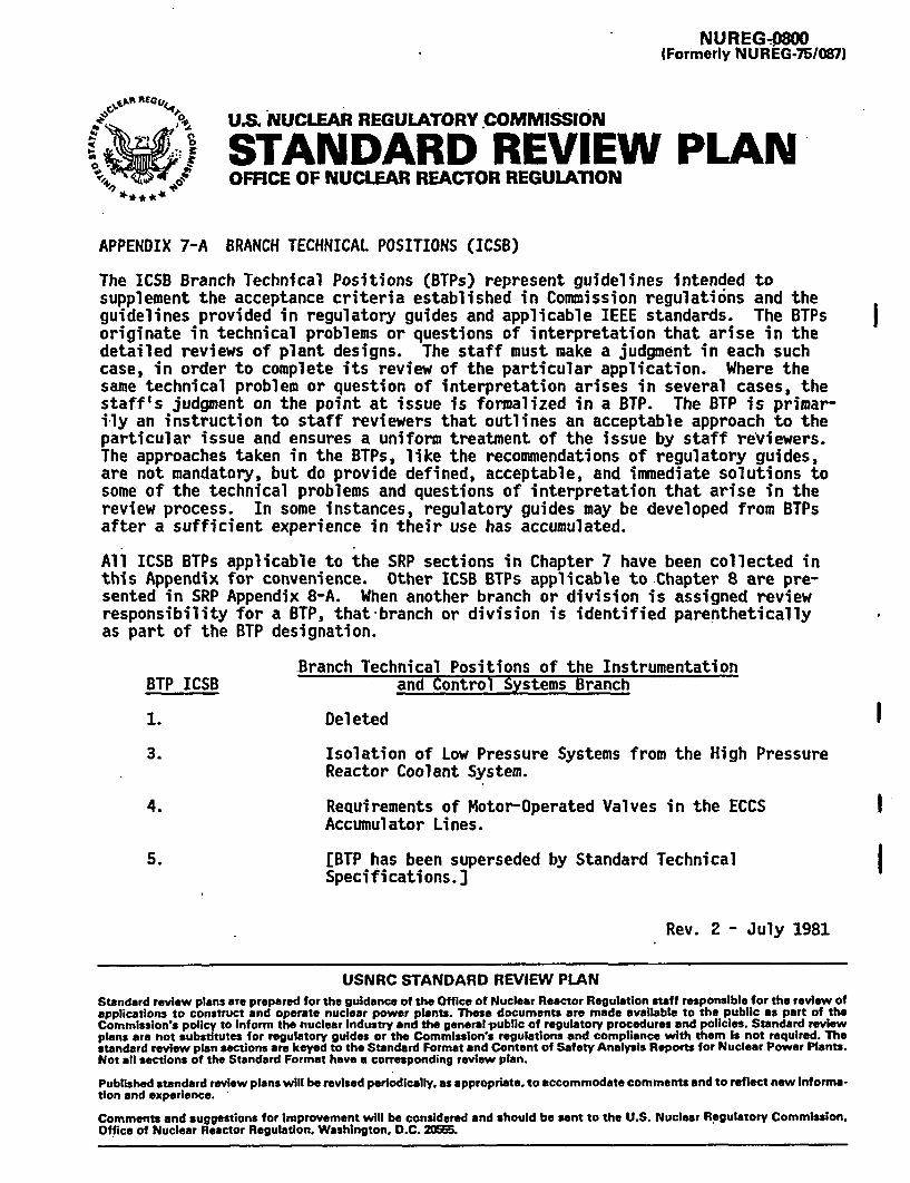
NUREG408OO (Formerly NUREG-75/087) ,^ @ U.S NUCLEAR REGULATORY COMMISSION STANDARD REVIEW PLAN OFFICE OF NUCLEAR REACTOR REGULATION APPENDIX 7-A BRANCH TECHNICAL POSITIONS (ICSB) The ICS8 Branch Technical Positions (BTPs) represent guidelines intended to supplement the acceptance criteria established in Commission regulations and the guidelines provided in regulatory guides and applicable IEEE standards. The BTPs originate in technical problems or questions of interpretation that arise in the detailed reviews of plant designs. The staff must make a judgment in each such case, in order to complete its review of the particular application. Where the same technical problem or question of interpretation arises in several cases, the staff's judgment on the point at issue is formalized in a BTP. The BTP is primar- ily an instruction to staff reviewers that outlines an acceptable approach to the particular issue and ensures a uniform treatment of the issue by staff reviewers. The approaches taken in the BTPs, like the recommendations of regulatory guides, are not mandatory, but do provide defined, acceptable, and immediate solutions to some of the technical problems and questions of interpretation that arise in the review process. In some instances, regulatory guides may be developed from BTPs after a sufficient experience in their use has accumulated. All ICSB BTPs applicable to the SRP sections in Chapter 7 have been collected in this Appendix for convenience. Other ICSB BTPs applicable to Chapter 8 are pre- sented in SRP Appendix 8-A. When another branch or division is assigned review responsibility for a BTP, that-branch or division is identified parenthetically as part of the BTP designation. Branch Technical Positions of the Instrumentation BTP ICSB and Control Systems Branch 1. Deleted 3. Isolation of Low Pressure Systems from the High Pressure Reactor Coolant System. 4. ReQuirements of Motor-Operated Valves in the ECCS Accumulator Lines. 5. [BTP has been superseded by Standard Technical Specifications.] Rev. 2 - July 1981 USNRC STANDARD REVIEW PLAN Standard review plans are prepared for the guidance of the Office of Nuclear Reactor Regulation staff responsible for the review of applications to construct and operate nuclear power plants. These documents are made available to the public as part of the Commission's policy to Inform the nuclear Industry and the general public of regulatory procedures and policies. Standard review plans are not substitutes for regulatory guides or the Commission's regulations and compliance with them Is not required. The standard review plan sections are keyed to the Standard Format and Content of Safety Analysis Reports for Nuclear Power Plants. Not all sections of the Standard Format have a corresponding review plan. Published standard review plans will be revised periodically, as appropriate, to accommodate comments and to reflect new Informa- tion and experience. Comments and suggestions for improvement will be considered and should be sent to the U.S. Nuclear Regulatory Commission, Office of Nuclear Reactor Regulation. Washington, D.C. 2
Transcript of NUCLEAR REGULATORY COMMISSION STANDARD REVIEW PLAN
NUREG408OO(Formerly NUREG-75/087)
,^ @ U.S NUCLEAR REGULATORY COMMISSION
STANDARD REVIEW PLANOFFICE OF NUCLEAR REACTOR REGULATION
APPENDIX 7-A BRANCH TECHNICAL POSITIONS (ICSB)
The ICS8 Branch Technical Positions (BTPs) represent guidelines intended tosupplement the acceptance criteria established in Commission regulations and theguidelines provided in regulatory guides and applicable IEEE standards. The BTPsoriginate in technical problems or questions of interpretation that arise in thedetailed reviews of plant designs. The staff must make a judgment in each suchcase, in order to complete its review of the particular application. Where thesame technical problem or question of interpretation arises in several cases, thestaff's judgment on the point at issue is formalized in a BTP. The BTP is primar-ily an instruction to staff reviewers that outlines an acceptable approach to theparticular issue and ensures a uniform treatment of the issue by staff reviewers.The approaches taken in the BTPs, like the recommendations of regulatory guides,are not mandatory, but do provide defined, acceptable, and immediate solutions tosome of the technical problems and questions of interpretation that arise in thereview process. In some instances, regulatory guides may be developed from BTPsafter a sufficient experience in their use has accumulated.
All ICSB BTPs applicable to the SRP sections in Chapter 7 have been collected inthis Appendix for convenience. Other ICSB BTPs applicable to Chapter 8 are pre-sented in SRP Appendix 8-A. When another branch or division is assigned reviewresponsibility for a BTP, that-branch or division is identified parentheticallyas part of the BTP designation.
Branch Technical Positions of the InstrumentationBTP ICSB and Control Systems Branch
1. Deleted
3. Isolation of Low Pressure Systems from the High PressureReactor Coolant System.
4. ReQuirements of Motor-Operated Valves in the ECCSAccumulator Lines.
5. [BTP has been superseded by Standard TechnicalSpecifications.]
Rev. 2 - July 1981
USNRC STANDARD REVIEW PLANStandard review plans are prepared for the guidance of the Office of Nuclear Reactor Regulation staff responsible for the review ofapplications to construct and operate nuclear power plants. These documents are made available to the public as part of theCommission's policy to Inform the nuclear Industry and the general public of regulatory procedures and policies. Standard reviewplans are not substitutes for regulatory guides or the Commission's regulations and compliance with them Is not required. Thestandard review plan sections are keyed to the Standard Format and Content of Safety Analysis Reports for Nuclear Power Plants.Not all sections of the Standard Format have a corresponding review plan.
Published standard review plans will be revised periodically, as appropriate, to accommodate comments and to reflect new Informa-tion and experience.
Comments and suggestions for improvement will be considered and should be sent to the U.S. Nuclear Regulatory Commission,Office of Nuclear Reactor Regulation. Washington, D.C. 2
9. [BTP has been superseded by Standard TechnicalSpecifications.]
12. Protection System Trip Point Changes for Operationwith Reactor Coolant Pumps Out of Service.
13. Design Criteria for Auxiliary Feedwater Systems.
14. Spurious Withdrawals of Single Control Rods inPressurized Water Reactor.
16. Deleted.
19. Deleted:
20. Design of Instrumentation and Controls Provided toAccomplish Changeover from Injection to RecirculationMode.
21. Guidance for Application of Regulatory Guide 1.47.
22. Guidance for Application of Regulatory Guide 1.22.
25. [BTP has been superseded by Standard TechnicalSpecifications.] I
26. Requirements for Reactor Protection SystemAnticipatory Trips.
7A-2 Rev. 2 - July 1981

BRANCH TECHNICAL POSITION ICSB I (DOR)BACKFITTING OF THE PROTECTION AND EMERGENCY POWER SYSTEMS OF NUCLEAR REACTORS
[BTP ICSB 1 has been deleted] I
7A-3 Rev. 2 - July 1981

BRANCH TECHNICAL POSITION ICSB 3ISOLATION OF LOW PRESSURE SYSTEMS FROM THE HIGH PRESSURE REACTOR COOLANT SYSTEM
A. BACKGROUND
During normal and emergency conditions, it is necessary to keep low pressuresystems that are connected to the high pressure reactor coolant systemproperly isolated in order to avoid'damage by overpressurization or thepotential for loss of integrity of the low pressure system and possibleradioactive releases. The residual heat removal system used for cold shutdownconditions when in service becomes an extension of the reactor coolantpressure boundary. General Design Criteria 15 requires that reactor coolantsystem and associated auxiliary, control and protection systems shall bedesigned with sufficient margin to assure that the design conditions of thereactor coolant pressure boundary are not exceeded during any condition ofnormal operation, including anticipated operational occurrences. There havebeen a number of recommendations for accomplishing this aim. Until a moredefinitive guide is published, the criteria in Part B, below, provide anadequate and acceptable design solution for this concern.
B. BRANCH TECHNICAL POSITION
The bbllowing measures should be incorporated in designs of the interfacesbetween low pressure systems and the high pressure reactor coolant system:
1. At least two valves in series should be provided to isolate any subsystemwhenever the primary system pressure is above the pressure rating of thesubsystem.
2. For system interfaces where both valves are motor-operated, the valvesshould have independent and diverse interlocks to prevent both fromopening unless the primary system pressure is below the subsystem designpressure. Also, the valve operators should receive a signal to closeautomatically whenever the primary system pressure exceeds the subsystemdesign pressure.
3. For those system interfaces where one check valve and one motor-operatedvalve are provided, the motor-operated valve should be interlocked toprevent the valve from opening whenever the primary pressure is above thesubsystem design pressure, and to close automatically whenever theprimary system pressure exceeds the subsystem design pressure.
4. Suitable valve position indication should be provided in the control roomfor the interface valves.
5. For those interfaces where the subsystem is required for ECCS operation,the above recommendations need not be implemented. System interfaces ofthis type should be evaluated on an individual case basis.
6. The system should satisfy the requirements of the General Design Criteriaand Section 50.55a(h) of 10 CFR Part 50 with regards to the protectionsystem requirements (IEEE Std 279).
C. REFERENCES
None
7A-4 Rev. 2 - July 1981

BRANCH TECHNICAL POSITION ICSB 4REQUIREMENTS OF MOTOR-OPERATED VALVES IN THE ECCS ACCUMULATOR LINES
A. BACKGROUND
For many postulated loss-of-coolant accidents, the performance of theemergency core cooling-system (ECCS) in pressurized water reactor plantsdepends upon properftnctioning of the safety injection tanks (also referredto as "accumulators" or "flooding tanks" in some applications). In theseplants, a motor-operated isolation valve (MOIV) and two check valves areprovided in series between each safety injection tank and the reactor coolant(primary) system.
The MOIVs must be considered to be "operating bypasses" because, when closed,they prevent the safety injection tanks from performing the intended protec-tive function. IEEE Std 279 has a requirement for "operating bypasses" whichstates that the bypasses of a protective function will be removed automati-cally whenever permissive conditions are not met. This Branch TechnicalPosition provides specific guidance in meeting the intent of IEEE Std 279 forsafety injection tank MOIVs.
It should be noted that BTP ICSB 18 (PSB), "Application of the Single FailureCriterion to Manually-Controlled Electrically-Operated Valves," also appliesto these isolation valves and should be used in conjunction with thisposition.
B. BRANCH TECHNICAL POSITION
The following features should be incorporated in the design of M0IV systemsfor safety injection tanks to meet the intent of IEEE Std 279:
1. Automatic opening of the valves when either primary coolant systempressure exceeds a preselected value (to be specified in the technicalspecifications), or a safety injection signal is present. Both primarycoolant system pressure and safety injection signals should be providedto the valve operator.
2. Visual indication in the control room of the open or closed status of thevalve.
3. Bypassed and inoperable status indication in accordance to RegulatoryGuide 1.47. |
4. Utilization of a safety injection signal to remove automatically(override) any bypass feature that may be provided to allow an isolationvalve to be closed for short periods of time when the reactor coolantsystem is at pressure (in accordance with provisions of the technicalspecifications).
C. REFERENCES
1. Arkansas 1, Unit 1, Safety Evaluation Report, January 23, 1973.
2. IEEE Std 279, "Criteria for Protection Systems for Nuclear PowerGenerating Stations."
7A-5 Rev. 2 - July 1981

3. BTP ICSB 18 (PSB), "Application of the Single Failure Criterion toManually-Controlled Electrically-Operated Valves."
7A-6 Rev. 2 - July 1981

BRANCH TECHNICAL POSITION ICSB 5SCRAM BREAKER TEST REQUIREMENTS - TECHNICAL SPECIFICATIONS
[BTP has been superseded by Standard Technical Specifications] I
7A-7 Rev. 2 - July 1981

BRANCH TECHNICAL POSITION ICSB 9DEFINITION AND USE OF "CHANNEL CALIBRATION" - TECHNICAL SPECIFICATIONS
[BTP has been superseded by Standard Technical Specifications] I
7A-8 Rev. 2 - July 1981

BRANCH TECHNICAL POSITION ICSB 12PROTECTION SYSTEM TRIP POINT CHANGES FOR OPERATION WITH REACTOR COOLANT
PUMPS OUT OF SERVICE
A. BACKGROUND
For the past several years, including a time prior to the development of IEEEStd 279, the staff has required automatic adjustment to more restrictivesettings of trips affecting reactor safety by means of circuits satisfying thesingle failure criterion. The basis for this requirement is that the functioncan be accomplished more reliably by automatic circuitry than by a humanoperator. This design practice, which has also been adopted independently bythe national laboratories and by much of industry, served as the basis forparagraph 4.15, "Multiple Set Points,' of IEEE Std 279.
More recently, all applicants have stated that their protection systems weredesigned to meet IEEE Std 279. Paragraph 4.15 of IEEE Std 279 specified thatwhere a mode of reactor operation requires a more restrictive set point, themeans for ensuring use of the more restrictive set point. shall be positive andmust meet the other requirements of IEEE Std 279. A number of designs havebeen proposed and accepted which reliably and simply satisfy this requirement.During the review of some applications, however, certain design deficiencieshave been found. The purpose of this position is to provide additionalguidance on the application of Section 4.15 of IEEE Std 279.
B. BRANCH TECHNICAL POSITION
1. If more restrictive safety trip points are required for operation with areactor coolant pump out of service, and if operation with a reactorcoolant pump out of service is of sufficient likelihood to be a plannedmode of operation, the change to the more restrictive trip points shouldbe accomplished automatically.
2. Plants with designs not in accordance with the above should have includedin the plant technical specifications a requirement that the reactor beshut down prior to changing the set points manually.
C. REFERENCES
1. Millstone-3 Safety Evaluation Report, September 24, 1973.
2. Beaver Valley-2 Safety Evaluation Report, October 10, 1973.
3. IEEE Std 279, "Criteria for Protection Systems for Nuclear PowerGenerating Stations."
7A-9 Rev. 2 - July 1981

BRANCH TECHNICAL POSITION ICSB 13DESIGN CRITERIA FOR AUXILIARY FEEDWATER SYSTEMS
A. BACKGROUND
The function of the auxiliary feedwater system in pressurized water reactorsis to provide an emergency source of feedwater supply to the steam generators.It is required to ensure safe shutdown in the event of a main turbine tripwith loss of offsite power. The system is also started on a safety injectionsignal. Feedwater is pumped to each steam generator through normally opencontrol valves. It was found that in some plant designs the auxiliaryfeedwater system did not meet the single failure criterion. It is the purposeof this Branch Technical Position to provide guidance and to establish uniformrequirements for acceptable designs of auxiliary feedwater systems.
B. BRANCH TECHNICAL POSITION
The auxiliary feedwater system should be capable of satisfying the systemfunctional requirements after a postulated break in the auxiliary feedwaterpiping inside containment together with a single electrical failure. Thebasis for the position is that an auxiliary feedwater piping break wouldresult in tripping the unit and, in turn, might cause loss of offsite power.Standard staff assumptions for analyzing postulated accidents include theassumption of loss of offsite power if the affected unit generator is trippedby the accident. Such a circumstance would leave the plant without adequatemeans for removal of afterheat even though the reactor coolant pressureboundary was intact, an unacceptable result. Plant heat removal systems must,in any postulated piping break, be capable of removing afterheat to theultimate heat sink assuming a single electrical (active) failure anywhere inthe auxiliary feedwater system or in the onsite power system.
C. REFERENCES
None
7A-10 Rev. 2 - July 1981

BRANCH TECHNICAL POSITION ICSB 14SPURIOUS WITHDRAWALS OF SINGLE CONTROL RODS IN PRESSURIZED WATER REACTORS
A. BACKGROUND
Recent operating experience with PWRs and subsequent reviews of PWR designswith regard to the requirements of General Design Criteria 20 and 25 haveshown that single failures can cause inadvertent single rod withdrawals. Theintent of this Branch Technical Position is to provide specific guidancetoward an acceptable interpretation and application of GDC 20 and 25.
B. BRANCH TECHNICAL POSITION
GDC 20 requires that the protection system shall be designed to initiateautomatically the operation of appropriate systems including the reactivitycontrol systems, to assure that specified acceptable fuel design limits arenot exceeded as a result of anticipated operational occurrences. GDC 25requires these limits shall not be exceeded for any single malfunction of thereactivity control systems, such as accidental withdrawal (not ejection) ofcontrol rods. Within the context of GDC 20 the staff considers operator errorto be an anticipated operational occurrence, in addition to the considerationof single malfunction requirements of GDC 25, for which conformance to theserequirements is to be evaluated. The applicant should perform analyses of thereactivity control systems* and analyze the consequences of operator error toassess the impact of these events on fuel design limits. If the results ofthese analyses show that specified acceptable fuel design limits may beexceeded for these events, the protection system must be designed to detectand terminate these events prior to exceeding these limits.
With regards to the evaluation of malfunctions within the reactivity controlsystems, consideration should be given to failures which cause actions as wellas prevent actions such that all possible effects are examined. Further,consideration of failures which could lead to single or multiple rod positionchanges or out of sequence rod patterns should be analyzed, as well as,failures which could lead to reactivity changes by boron control systems.
C. REFERENCES
1. Surry 3 and 4 Safety Evaluation Report, March 26, 1974.
2. 10 CFR Part 50, Appendix A, General Design Criteria.
Reactivity control systems include interlocks within the system which limitthe consequences of control system failures.
7A-11' Rev. 2 - July 1981

BRANCH TECHNICAL POSITION ICSB 16CONTROL ELEMENT ASSEMBLY (CEA) INTERLOCKS IN COMBUSTION ENGINEERING REACTORS
[BTP has been deleted] )
7A^12 Rev. 2 - July 1981

BRANCH TECHNICAL POSITION ICSB 19ACCEPTABILITY OF DESIGN-CRITERIA FOR HYDROGEN MIXING AND DRYWELL
VACUUM RELIEF SYSTEMS
[BTP.has been deleted]
7A-13 Rev. 2 - July 1981

- -
BRANCH TECHNICAL POSITION ICSB 20DESIGN OF INSTRUMENTATION. AND CONTROLS PROVIDED TO
ACCOMPLISH CHANGEOVER FROM INJECTION-TO RECIRCULATION MODE
A. BACKGROUND
Designs are reviewed with regard to the automatic and manual initiation ofprotective actions, as set forth in paragraph 4.17 of IEEE Std 279; For somerecent designs, the staff concluded that the proposed design of the circuitsused to change over to the recirculation mode of operation following aloss-of-coolant accident did not conform to IEEE Std 279, and the complexityof the proposed changeover procedure raised questions as to whether theoperator could be expected to perform correctly the required actions withinthe time and based on the information available to him.
B. BRANCH TECHNICAL POSITION
1. A design that provides manual initiation at the system level of thetransfer to the recirculation mode, while not ideal, is sufficient andsatisfies the intent of IEEE Std 279 provided that adequate instrumenta-tion and information display are available to the operator so that he canmake the correct decision at the correct time. Furthermore, it should beshown that, in case of operator error, there are sufficient time andinformation available so that the operator can correct the error, and theconsequences of such an error are acceptable.
2. Automatic transfer to the recirculation mode is preferable to manualtransfer, for the reasons cited above, and should be provided forstandard plant designs submitted for review on a generic basis under theCommission's standardization policy.
C. REFERENCES
1. IEEE Std 279, "Criteria for Protection Systems for Nuclear PowerGenerating Stations."
7A-14 Rev. 2 - July 1981

BRANCH TECHNICAL POSITION ICSB 21GUIDANCE FOR APPLICATION OF REGULATORY GUIDE 1.47
A. BACKGROUND
The recommendations of Regulatory Guide 1.47 need further detailing as tomethods of providing an acceptable design for-the bypass and inoperable statusindicators for engineered safety feature (ESF) systems. The purpose of thisBranch Technical Position is to provide supplemental guidance forimplementation of the recommendations of Regulatory Guide 1.47.
B. BRANCH TECHNICAL POSITION
The design criteria for bypass and inoperable status indication systems forESF should reflect the importance of providing accurate information for theoperator and reducing the possibility for the indicating equipment to affectadversely the monitored safety systems. In developing the design criteria,the following should be considered:
1. The bypass indicators should be arranged to enable the operator todetermine the- status of each safety system and determine whethercontinued reactor operation is permissible.
2. When a protective function of a shared system can be bypassed, indicationof that bypass condition should be provided in the control room of eachaffected unit.
3. Means by which the operator can cancel erroneous bypass. indications, ifprovided, should be justified by demonstrating that the postulated casesof erroneous indications cannot be eliminated by another practicaldesign.
4. Unless the indication system is designed in conformance with criteriaestablished for safety systems, it should not be used to performfunctions that are essential to safety; Administrative procedures shouldnot require immediate operator action based solely on the bypassindications.
5. The indication system should be designed and installed in a manner whichprecludes the possibility of adverse effects on plant safety systems.Failure or bypass of a protective function -should not be a credibleconsequence of failures occurring in the indication equipment, and thebypass indication should not reduce the required independence betweenredundant safety systems.
6. The indication system should include a capability of assuring itsoperable status during normal plant operation to the extent that/ heindicating and annunciating function can be verified.
C. REFERENCES
1. Regulatory Guide 1.47, "Bypassed and Inoperable Status Indication forNuclear Power Plant Safety Systems."
7A-15 Rev. 2 - July 1981

BRANCH TECHNICAL POSITION ICSB 22GUIDANCE FOR APPLICATION OF REGULATORY GUIDE 1.22
A. BACKGROUND
A recent application listed eight functions that are not tested while thereactor is operating at power. The applicant claimed that the periodictesting complied with Regulatory Guide 1.?2. -Regulatory Guide 1.22 does makeprovisions for actuated equipment that is not tested during reactor operationbut it does not have provisions for excluding any portion of the protectionsystem from the requirements of paragraphs 4.9 and 4.10 of IEEE Std 279.
B. BRANCH TECHNICAL POSITION
All portions of the protection systems should be designed in accordance withIEEE Std 279, as required by 10 CFR Part 50, §50.55a(h). All actuatedequipment that is-not tested during reactor operation should be identified anda discussion of. how each conforms to the provisions of paragraph D.4 ofRegulatory Guide 1.22 should be submitted.
C. REFERENCES
1. Regulatory Guide 1.22, "Periodic Testing of Protection System ActuationFunctions."
2. IEEE Std 279, "Criteria for Protection Systems for Nuclear PowerGenerating Stations."
7A-16 Rev. 2 - July 1981

BRANCH TECHNICAL POSITION ICSB 25GUIDANCE FOR THE INTERPRETATION OF GENERAL.DESIGN CRITERION. 37 FOR TESTING THE
- OPERABILITY.-OF THE EMERGENCY CORE COOLING SYSTEM AS A WHOLE
[BTP has been superseded by Standard Technical SpecificationsJ I
7A-17 Rev. 2 - July 1981

-BRANCH TECHNICAL POSITION ICSB 26REQUIREMENTS FOR REACTOR PROTECTION SYSTEM ANTICIPATORY TRIPS
A. BACKGROUND
Several reactor designs have incorporated a number of anticipatory or"back-up" trips for which no 'credit was taken in the accident analyses. Thesetrips, as a rule, were not designed to the requirements of IEEE Std 279 andtherefore introduced nonsafety grade equipment into the reactor protectionsystem. It was determined by the staff that this was not an acceptablepractice, because of possible degradation of the reactor protection system.
B. BRANCH TECHNICAL POSITION.
All reactor trips incorporated in the reactor protection system should bedesigned to meet the requirements of IEEE Std 279. This position applies tothe entire trip function from the sensor to the final actuated device. Forsensors located in nonseismic areas the installation (including circuitrouting) and design should be such that the effects of credible faults (i.e.grounding, shorting, application of high voltage, or electromagnetic inter-ference) or failures in these areas could not be propagated back to the RPSand degrade the RPS performance or reliability. The sensors should bequalified to operate in a seismic event, i.e., not fail to initiate a trip forconditions which would cause a trip.
C. REFERENCES
1. Shearon Harris Safety Evaluation Report, September 15, 1972.
2. IEEE Std 279, "Criteria forGenerating Stations."
Protection Systems for Nuclear Power
3. NUREG 0718 and 0737, Items II.K.2.10* and II.K.3.12.
Task Action Plan item II.K.1.21 has been superseded by item II.K.2.10.
I
I
7A-18 Rev. 2 - July 1981