
Unit-IV Railway Engineering
177
PREPARED BY M.SHANMUGARAJ LECTURER / CIVIL V . S .V. N . P O L Y T E CH N I C COL L E G E V IR U D H U N A G A R UNIT-IV RAILWAY ENGINEERING
Transcript of Unit-IV Railway Engineering

8/13/2019 Unit-IV Railway Engineering
http://slidepdf.com/reader/full/unit-iv-railway-engineering 1/177
P R E P A R E D B Y
M . S H A N M U G A R A J
L E C T U R E R / C I V I L
V . S . V . N . P O L Y T E C H N I C C O L L E G E
V I R U D H U N A G A R
UNIT-IV RAILWAY
ENGINEERING

8/13/2019 Unit-IV Railway Engineering
http://slidepdf.com/reader/full/unit-iv-railway-engineering 2/177
Station and Yards
Definition of Station
A railway station or a railroad station and oftenshortened to just station, is a railway facility
where trains regularly stop to load orunload passengers and/or freight

8/13/2019 Unit-IV Railway Engineering
http://slidepdf.com/reader/full/unit-iv-railway-engineering 3/177
Station and Yards

8/13/2019 Unit-IV Railway Engineering
http://slidepdf.com/reader/full/unit-iv-railway-engineering 4/177
Purpose of Railway station
For exchange of passengers and goods. For control of train movements To enable the trains on a single line track to cross from
opposite directions. To enable the following express trains to overtake For taking diesel or coal and water for locomotives For detaching engines and running staff For detaching or attaching of compartments and wagons For sorting of bogies to form new trains, housing of
locomotive in loco sheds. In emergencies in ease of dislocation of track due to rains,
accidents etc... For repairing engines and changing their direction Railway station are having suitable approach roads from
surrounding areas.

8/13/2019 Unit-IV Railway Engineering
http://slidepdf.com/reader/full/unit-iv-railway-engineering 5/177
Types of Stations
Wayside Stations, Junction Stations, TerminalStations

8/13/2019 Unit-IV Railway Engineering
http://slidepdf.com/reader/full/unit-iv-railway-engineering 6/177
Wayside Stations
In this type arrangements are made for crossing orfor overtaking trains. Wayside stations are of thefollowing types.
i.Halt stations, ii.Flag Stations, iii.Crossing stations

8/13/2019 Unit-IV Railway Engineering
http://slidepdf.com/reader/full/unit-iv-railway-engineering 7/177
Halt Stations
A halt, is a small station, usually unstaffed and withfew or no facilities. In some cases, trains stop onlyon request, when passengers on the platformindicate that they wish to board, or passengers onthe train inform the crew that they wish to alight.

8/13/2019 Unit-IV Railway Engineering
http://slidepdf.com/reader/full/unit-iv-railway-engineering 8/177
Halt Stations

8/13/2019 Unit-IV Railway Engineering
http://slidepdf.com/reader/full/unit-iv-railway-engineering 9/177
Flag Stations
Flag stations describes a stopping point at whichtrains stop only on an as-need or request basis; thatis, only if there are passengers to be picked up ordropped off.
These stations have no overtaking or crossingfacilities and arrangements to control the movementof trains. These stations have buildings, staff and
telegraph facilities. Some of the flag stations have sidings also in the
form of loops.

8/13/2019 Unit-IV Railway Engineering
http://slidepdf.com/reader/full/unit-iv-railway-engineering 10/177
Flag Stations

8/13/2019 Unit-IV Railway Engineering
http://slidepdf.com/reader/full/unit-iv-railway-engineering 11/177
Crossing Stations
Provided with facilities for crossing
In this type at least one loop line is provided to allowanother train if one track is already occupied by a
waiting train Generally the train to be stopped is taken on the loop
line and the through train is allowed to pass on themain line

8/13/2019 Unit-IV Railway Engineering
http://slidepdf.com/reader/full/unit-iv-railway-engineering 12/177
Crossing Stations

8/13/2019 Unit-IV Railway Engineering
http://slidepdf.com/reader/full/unit-iv-railway-engineering 13/177
Junction stations:
At a junction stations, lines from three or more directionsmeet
The stations where a branch line meets the main line areknown as junctions.
Arrangements in junction stations
Facilities for interchange of traffic between main and branch line
Facilities to clean and repair the compartments of thetrains
Facilities for good sidings, engine sheds, turn table etc.

8/13/2019 Unit-IV Railway Engineering
http://slidepdf.com/reader/full/unit-iv-railway-engineering 14/177
Junction stations:
8/13/2019 Unit-IV Railway Engineering
http://slidepdf.com/reader/full/unit-iv-railway-engineering 15/177
Terminal Stations:
It is a station where a railway line or one of its branches terminates
Facilities required in terminal stations
Watering, coaling, cleaning, servicing the engine Turn table for the change of direction of the engine
Facilities for dealing goods traffic. Such asmarshalling yard, engine sheds, sidings etc.
In circulating area, ticket office, restaurant etc areprovided and it is directly connected to the road

8/13/2019 Unit-IV Railway Engineering
http://slidepdf.com/reader/full/unit-iv-railway-engineering 16/177
Terminal Stations:

8/13/2019 Unit-IV Railway Engineering
http://slidepdf.com/reader/full/unit-iv-railway-engineering 17/177
8/13/2019 Unit-IV Railway Engineering
http://slidepdf.com/reader/full/unit-iv-railway-engineering 18/177
Block Stations:
The stations at the end the block sections are called Blockstations
Authority to proceed is given in the shape of token atthese stations.
Class A Station: On these stations the track is cleared up to 400m beyondthe home signal for giving permission to approach a train
Class B Station: In such stations, the other signal is provided at about
580m from the home signalClass C Station: On these stations passengers are not booked. It is simply
a block meant for splitting a long block section and toreduce the interval between the successive trains.

8/13/2019 Unit-IV Railway Engineering
http://slidepdf.com/reader/full/unit-iv-railway-engineering 19/177
Non Block Stations:
Also known as Class D station or Flag station
Situated between two consecutive block stations
May not be telegraphically connected to the
adjacent stations No equipment or staff is provided for controlling
the movements of the trains.
Trains are stopped by flag signals only

8/13/2019 Unit-IV Railway Engineering
http://slidepdf.com/reader/full/unit-iv-railway-engineering 20/177
Special class stations:
Stations not coming under block station and non block stations are called special class station

8/13/2019 Unit-IV Railway Engineering
http://slidepdf.com/reader/full/unit-iv-railway-engineering 21/177
Platforms - Passenger and Goods platforms:
A railway platform is a section of pathway, alongside railtracks at a railway station, metro station or tram stop, at which passengers may board or alight from trains or trams.
Almost all rail stations have some form of platform, withlarger stations having multiple platforms.
Platform types include the bay platform, sideplatform (also called through platform), splitplatform and the island platform.
A bay platform is one at which the track terminates, i.e. adead-end or siding.
A side platform is the more usual type, alongside tracks where the train arrives from one end and leaves towards theother.
An island platform has through platforms on both sides; itmay be indented on one or both ends, with bay platforms.

8/13/2019 Unit-IV Railway Engineering
http://slidepdf.com/reader/full/unit-iv-railway-engineering 22/177
Passenger Platform

8/13/2019 Unit-IV Railway Engineering
http://slidepdf.com/reader/full/unit-iv-railway-engineering 23/177
Goods Platform

8/13/2019 Unit-IV Railway Engineering
http://slidepdf.com/reader/full/unit-iv-railway-engineering 24/177
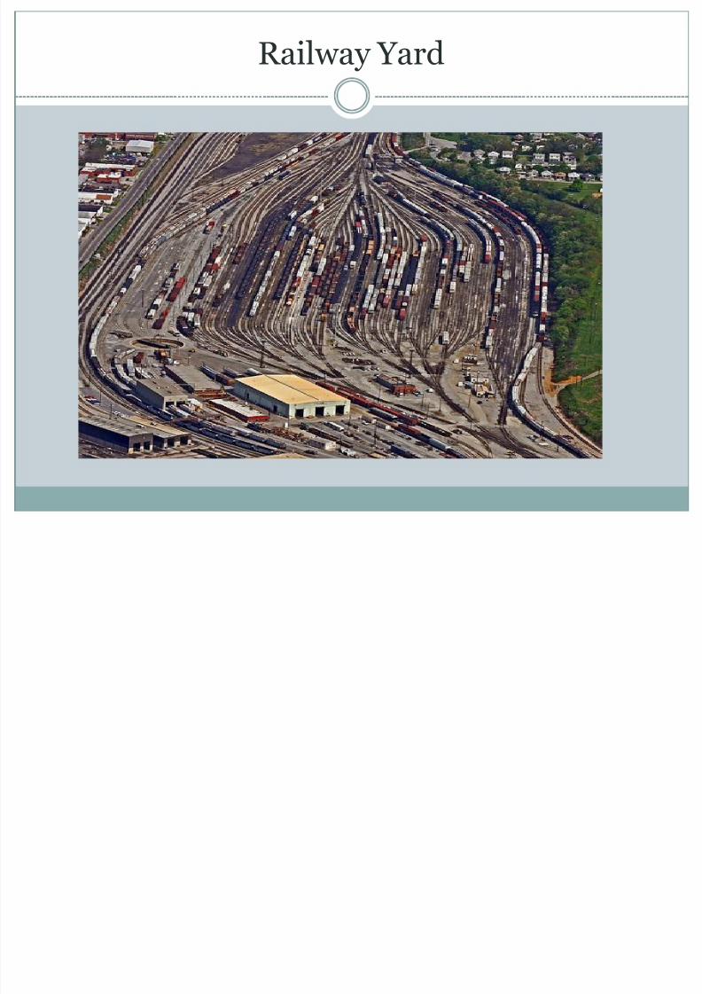
Definition of Yard:
An area consisting of a network of railway tracks,sidings, and sheds for storing, maintaining, and
joining engines and carriages.
A yard is defined as a system of tracks laid withindefinite limits for various purposes such as receivingsorting and dispatch of vehicles.
8/13/2019 Unit-IV Railway Engineering
http://slidepdf.com/reader/full/unit-iv-railway-engineering 25/177
Railway Yard

8/13/2019 Unit-IV Railway Engineering
http://slidepdf.com/reader/full/unit-iv-railway-engineering 26/177
Types of Yards:
Passenger yards, Goods yards, Marshalling yards,Locomotive yards

8/13/2019 Unit-IV Railway Engineering
http://slidepdf.com/reader/full/unit-iv-railway-engineering 27/177
Passenger yards:
Function of passenger yard is to provide all the facilitiesfor the safe movement of passengers.
Facilities in passenger yards
Booking office, enquiry office, luggage booking room,
cloak room and waiting room for passengers Parking space for vehicles
Signals for reception and dispatch of trains
Platforms and sidings for shunting facilities
Facilities for changing batteries Facilities for passing a through train
Washing lines, sick lines facilities

8/13/2019 Unit-IV Railway Engineering
http://slidepdf.com/reader/full/unit-iv-railway-engineering 28/177
Passenger yards

8/13/2019 Unit-IV Railway Engineering
http://slidepdf.com/reader/full/unit-iv-railway-engineering 29/177
Goods yards:
A goods station (also known as a goods yard, goods depot or freight station) is, inthe widest sense, a railway station which isexclusively or predominantly where goods(or freight) of any description are loaded orunloaded from ships or road vehicles and/or where goods wagons are transferred to localsidings.
These are provided for receiving, loading andunloading of goods

8/13/2019 Unit-IV Railway Engineering
http://slidepdf.com/reader/full/unit-iv-railway-engineering 30/177

8/13/2019 Unit-IV Railway Engineering
http://slidepdf.com/reader/full/unit-iv-railway-engineering 31/177
Requirements of a goods yard
Approach road for movement of goods
Sufficient number of platforms for loading andunloading
Sufficient number of godowns Booking office
Cart weighing machine
Cranes for loading and unloading
Vacuum testing machine

8/13/2019 Unit-IV Railway Engineering
http://slidepdf.com/reader/full/unit-iv-railway-engineering 32/177
Marshalling yards:
Marshalling yard is a railroad yard found atsome freight train stations, used to separate railroadcars on to one of several tracks
It is the place where goods wagons received fromdifferent centres are sorted out and placed in orderto detached at different stations
The marshalling yards are distribution centres
Empty wagons are also kept in marshalling yards

8/13/2019 Unit-IV Railway Engineering
http://slidepdf.com/reader/full/unit-iv-railway-engineering 33/177
Marshalling yards:

8/13/2019 Unit-IV Railway Engineering
http://slidepdf.com/reader/full/unit-iv-railway-engineering 34/177
Factors for the efficient functioning ofmarshalling yards
Shunting operations should not disturb the regulartrains
Should be kept parallel to the running trains
Movement of wagons in one direction only Repair facilities should be provided on one or more
sidings
Connected to all important railway stations
Goods yard should be nearer to the marshalling yard

8/13/2019 Unit-IV Railway Engineering
http://slidepdf.com/reader/full/unit-iv-railway-engineering 35/177
Types of marshalling yards:
(i)Flat yard (ii)Gravity yard (iii)Hump yard

8/13/2019 Unit-IV Railway Engineering
http://slidepdf.com/reader/full/unit-iv-railway-engineering 36/177
Flat yard:
Flat yards are constructed on flat ground, or on agentle slope. Freight vehicles are pushed by alocomotive and coast to their required location.
A flat yard has no hump, and relies on locomotivesfor all car movements

8/13/2019 Unit-IV Railway Engineering
http://slidepdf.com/reader/full/unit-iv-railway-engineering 37/177
Gravity yard:
The whole yard is set up on a continuous fallinggradient and there is less use of shunting engines.
Typical locations of gravity yards are places where it
was difficult to build a hump yard due tothe topography
Gravity yards also have a very large capacity but theyneed more staff than hump yards and thus they are
the most uneconomical classification yards.

8/13/2019 Unit-IV Railway Engineering
http://slidepdf.com/reader/full/unit-iv-railway-engineering 38/177
Hump-yard:
These are the largest and most effective classification yards, with the largest shunting capacity —often severalthousand cars a day.
The heart of these yards is the hump: a lead track on a
hill (hump) that an engine pushes the cars over.
Single cars, or some coupled cars in a block, areuncoupled just before or at the crest of the hump, androll by gravity onto their destination tracks
A hump yard has a constructed hill, over which freightcars are shoved by yard locomotives, and then gravity isused to propel the cars to various sorting tracks

8/13/2019 Unit-IV Railway Engineering
http://slidepdf.com/reader/full/unit-iv-railway-engineering 39/177
Hump-yard:

8/13/2019 Unit-IV Railway Engineering
http://slidepdf.com/reader/full/unit-iv-railway-engineering 40/177
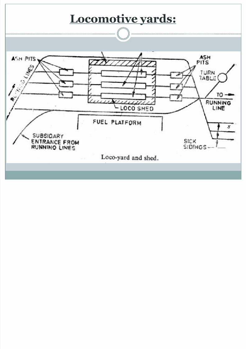
Locomotive yards:
This is the yard which houses the locomotives for various facilities such as watering, fueling, cleaning,repairing, servicing etc.
8/13/2019 Unit-IV Railway Engineering
http://slidepdf.com/reader/full/unit-iv-railway-engineering 41/177
Locomotive yards:

8/13/2019 Unit-IV Railway Engineering
http://slidepdf.com/reader/full/unit-iv-railway-engineering 42/177
Locomotive yards:
8/13/2019 Unit-IV Railway Engineering
http://slidepdf.com/reader/full/unit-iv-railway-engineering 43/177
Requirements of a locomotive yard
Should be located near the passenger and goods yards
Water column
Engine shed, Ash pit, inspection pit, repair shed,turn table
Hydraulic jack for lifting operations
Over head tank and loco well
Sick siding
Place for future expansion

8/13/2019 Unit-IV Railway Engineering
http://slidepdf.com/reader/full/unit-iv-railway-engineering 44/177
Level crossings
A level crossing (a primarily British term; usuallyknown as a railroad crossing in the United States) isan intersection where a railway line crossesa road or path at the same level
Other names include railway crossing, gradecrossing, road through railroad, and train crossing.
The type of facilities provided at level crossingdepends up on the following
Nature of the road Nature of the traffic on road
Number of trains passing over the level crossing

8/13/2019 Unit-IV Railway Engineering
http://slidepdf.com/reader/full/unit-iv-railway-engineering 45/177
Level crossings

8/13/2019 Unit-IV Railway Engineering
http://slidepdf.com/reader/full/unit-iv-railway-engineering 46/177
Classification of level crossing:
Special class – Traffic is exceptionally heavy
A class – On grand trunk roads
B class – Metelled roads
C class – unmetelled roads D class – used for cattle‘s as ramps and pedestrians
only

8/13/2019 Unit-IV Railway Engineering
http://slidepdf.com/reader/full/unit-iv-railway-engineering 47/177
Station Equipments
For efficient running of trains, safety of traffic,repairing, cleaning, examining of locomotives etc.some equipments and machinery is needed. Theseequipments are known as station equipment
8/13/2019 Unit-IV Railway Engineering
http://slidepdf.com/reader/full/unit-iv-railway-engineering 48/177
Engine sheds:
Railway engine sheds were provided at terminalstations, junctions, and other locations around therailway.
They provided covered accommodation for servicinglocomotives - this could be simple tasks such aschanging brake blocks to more complex task thatinvolved dismantling and repairing the engine.
Types of engine sheds are (i) Rectangular type (ii)Circular type

8/13/2019 Unit-IV Railway Engineering
http://slidepdf.com/reader/full/unit-iv-railway-engineering 49/177
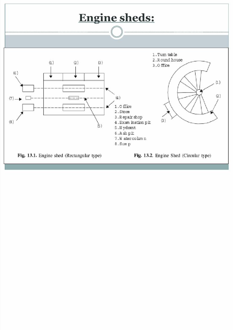
Rectangular type engine shed:
In this type of engine shed, two parallel tracks arelaid, which meet at one or both the ends.
The engine can come from one end and leave theshed in other end
They need more space; they are widely used in India

8/13/2019 Unit-IV Railway Engineering
http://slidepdf.com/reader/full/unit-iv-railway-engineering 50/177
Rectangular type engine shed:
8/13/2019 Unit-IV Railway Engineering
http://slidepdf.com/reader/full/unit-iv-railway-engineering 51/177
Engine sheds:

8/13/2019 Unit-IV Railway Engineering
http://slidepdf.com/reader/full/unit-iv-railway-engineering 52/177
Circular type engine shed:

8/13/2019 Unit-IV Railway Engineering
http://slidepdf.com/reader/full/unit-iv-railway-engineering 53/177
Circular type engine shed:
This type of shed consists of radiating tracks and acircular structure known as round house
A turn table is also provided with the help of turntable the incoming locomotive is put up on the unoccupied track of the shed
Needs less place
Skilled labour is needed for the construction

8/13/2019 Unit-IV Railway Engineering
http://slidepdf.com/reader/full/unit-iv-railway-engineering 54/177
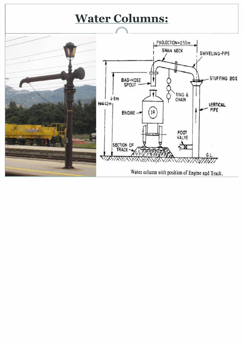
Water Columns:
A water crane is a device used for delivering a large volume of water into the tank or tender of a steamlocomotive. The device is sometimes also called a watercolumn.
As a steam locomotive consumes large quantities of water, water cranes were a vital part of railway station equipment,often situated at the end of a platform, so that water could be refilled during a stop at the station.
They are kept at all main line tracks at a distance of not lessthan 50Km.
It should not any obstruction to traffic Foot valve is provided to regulate the water flow Height of water column is 442cm Projection of pipe is about 225 cms
8/13/2019 Unit-IV Railway Engineering
http://slidepdf.com/reader/full/unit-iv-railway-engineering 55/177

8/13/2019 Unit-IV Railway Engineering
http://slidepdf.com/reader/full/unit-iv-railway-engineering 56/177
Water Column & Ash Pit
8/13/2019 Unit-IV Railway Engineering
http://slidepdf.com/reader/full/unit-iv-railway-engineering 57/177
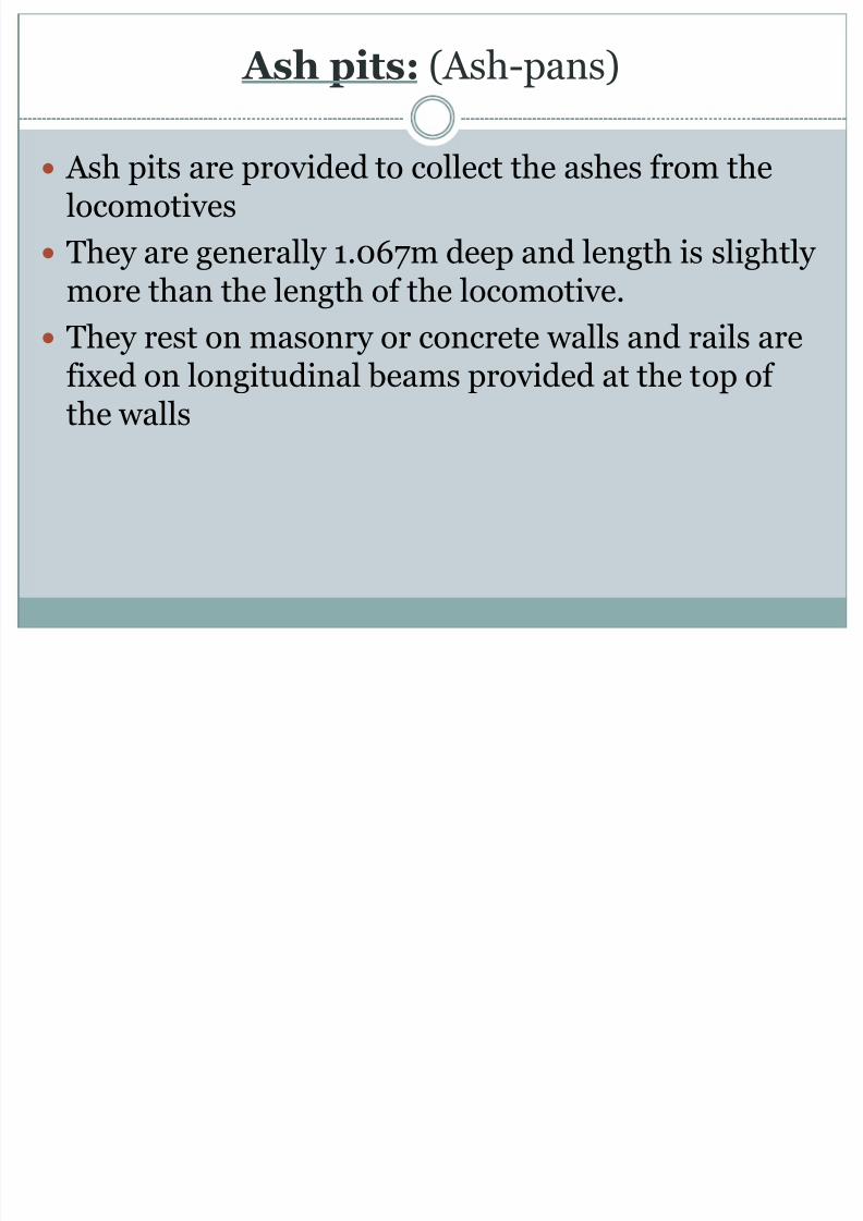
Ash pits: (Ash-pans)
Ash pits are provided to collect the ashes from thelocomotives
They are generally 1.067m deep and length is slightlymore than the length of the locomotive.
They rest on masonry or concrete walls and rails arefixed on longitudinal beams provided at the top ofthe walls

8/13/2019 Unit-IV Railway Engineering
http://slidepdf.com/reader/full/unit-iv-railway-engineering 58/177
Turn table:
A turntable is a device used to turn railroad rolling stock. Turntables were also used to turn observation cars so that
their windowed lounge ends faced toward the rear of the train.
A turntable is a large circular platform which is used to turnlocomotives and other rolling stock for railways.
A well-engineered turntable is designed in such a way that theefforts of only two or three people are needed to operate theturntable, even when dealing with very large and heavylocomotives
The reason the turntable was developed was because earlysteam locomotives were somewhat difficult to run in reverse
As a result, train companies started building turntables sothat they could quickly turn their locomotives around.

8/13/2019 Unit-IV Railway Engineering
http://slidepdf.com/reader/full/unit-iv-railway-engineering 59/177

8/13/2019 Unit-IV Railway Engineering
http://slidepdf.com/reader/full/unit-iv-railway-engineering 60/177

8/13/2019 Unit-IV Railway Engineering
http://slidepdf.com/reader/full/unit-iv-railway-engineering 61/177
Triangles:
Triangles are used for turning railway equipment By performing the railway equivalent of a three-point
turn, the direction of a locomotive or railway vehiclecan be swapped around, leaving it facing in the
direction from which it came It consists of three short lengths of tracks laid to
form a triangle and connected to each other by threepairs of points and crossings. Two tracks are laid in
curves and third as straight. The engine moves completely round the triangle and
its direction is automatically changed

8/13/2019 Unit-IV Railway Engineering
http://slidepdf.com/reader/full/unit-iv-railway-engineering 62/177
Triangle

8/13/2019 Unit-IV Railway Engineering
http://slidepdf.com/reader/full/unit-iv-railway-engineering 63/177
Buffer Stops:
A buffer stop or bumper is a device toprevent railway vehicles from going past the end of aphysical section of track
The design of the buffer stop is dependent in partupon the kind of couplings that the railway uses,since the coupling gear is the first part of the vehiclethat the buffer stop touches
It consists of timber beam 30x13cm section of thelevel of buffer on vehicles, fixed to the two verticalrail parts bolted to the track rails on other ends.
ff

8/13/2019 Unit-IV Railway Engineering
http://slidepdf.com/reader/full/unit-iv-railway-engineering 64/177
Buffer Stops:
ff

8/13/2019 Unit-IV Railway Engineering
http://slidepdf.com/reader/full/unit-iv-railway-engineering 65/177
Buffer Stops:
li k

8/13/2019 Unit-IV Railway Engineering
http://slidepdf.com/reader/full/unit-iv-railway-engineering 66/177
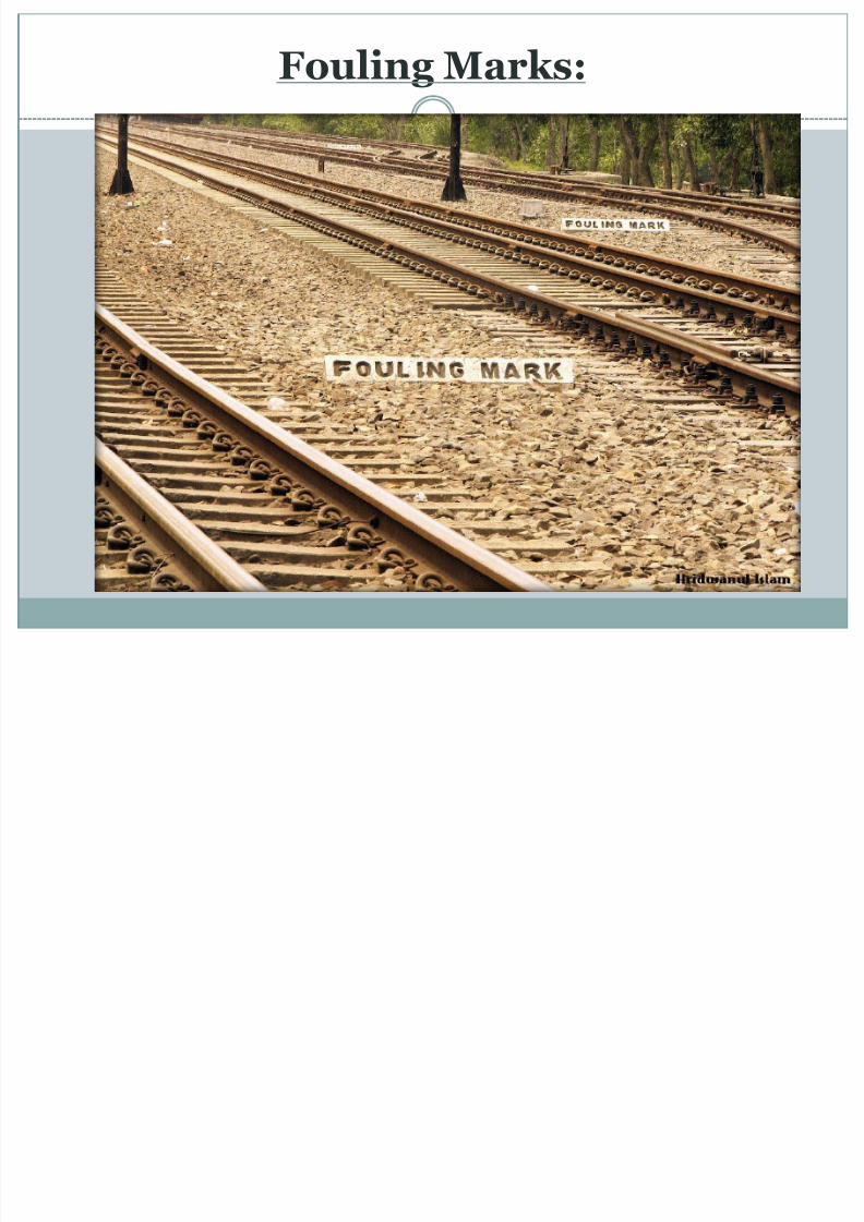
Fouling Marks:
Purpose is to avoid side collision between two trainson adjacent track.(in between diverging/convergingtracking rear of t/in curve)
It should be fixed at the point where the spacing between the tracks begins to reduce to less than theminimum as specified in schedule of dimension.(i.e.4.27 Meter track centre normally)
They are made up of stone or concrete blocks andpainted in black and white
F li M k

8/13/2019 Unit-IV Railway Engineering
http://slidepdf.com/reader/full/unit-iv-railway-engineering 67/177
Fouling Marks:
F li M k
8/13/2019 Unit-IV Railway Engineering
http://slidepdf.com/reader/full/unit-iv-railway-engineering 68/177
Fouling Marks:
E i i i

8/13/2019 Unit-IV Railway Engineering
http://slidepdf.com/reader/full/unit-iv-railway-engineering 69/177
Examination pits:
Examination pits are similar to ash pits but they areused to examine the engines from underneath.
These pits are generally longer and deeper than theash-pits
Provided in locomotive yards
E i ti it

8/13/2019 Unit-IV Railway Engineering
http://slidepdf.com/reader/full/unit-iv-railway-engineering 70/177
Examination pits
T

8/13/2019 Unit-IV Railway Engineering
http://slidepdf.com/reader/full/unit-iv-railway-engineering 71/177
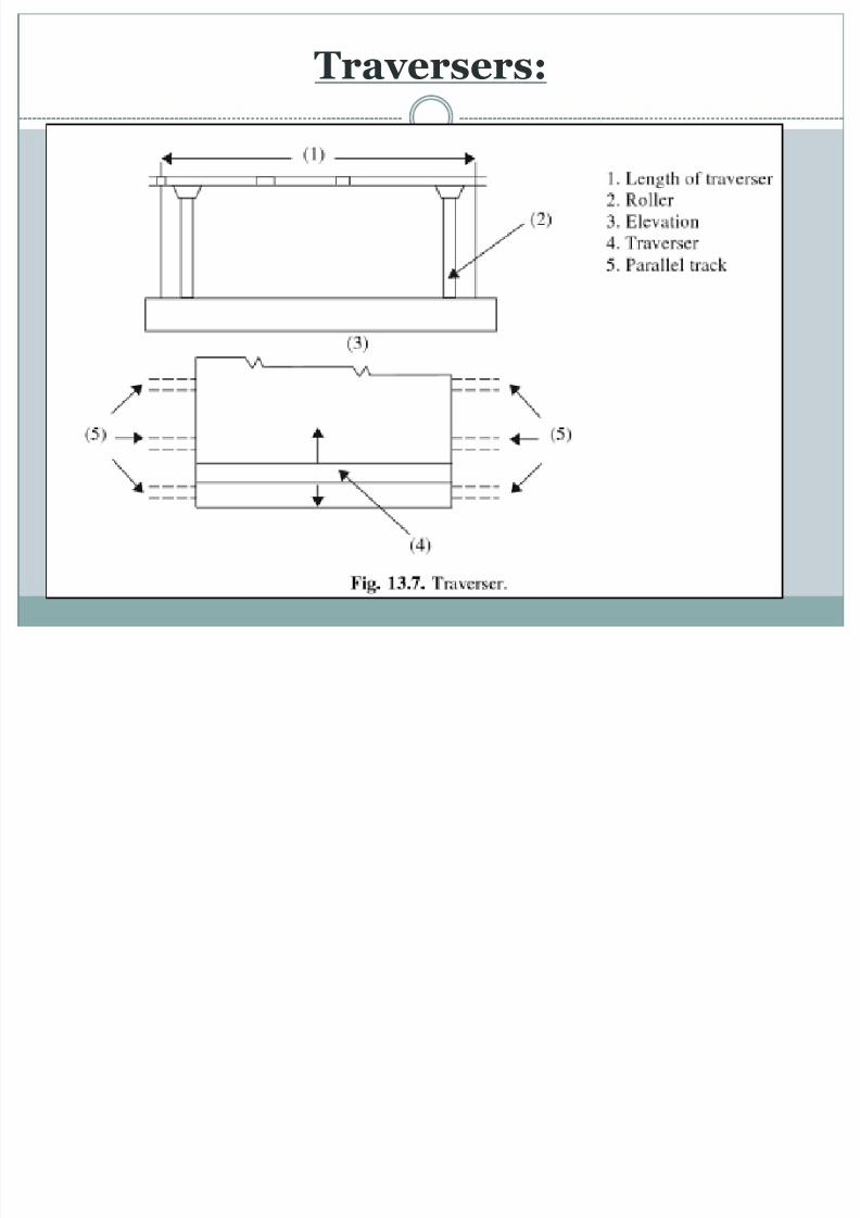
Traversers:
Traversers are used to shift the position of the vehicles or locomotives sideways
They provide an arrangement of transferring enginesand vehicles from one track to a parallel track
Traversers are preferred to turnouts, cross-overs, etc.
It consists of a platform mounted on rollers.
Vehicle to be shifted is placed on the traverser and
then the traverse is moved sideways and adjusted tothe parallel track where the vehicle is to be placed
T
8/13/2019 Unit-IV Railway Engineering
http://slidepdf.com/reader/full/unit-iv-railway-engineering 72/177
Traversers:
T

8/13/2019 Unit-IV Railway Engineering
http://slidepdf.com/reader/full/unit-iv-railway-engineering 73/177
Traversers:
D ili it h

8/13/2019 Unit-IV Railway Engineering
http://slidepdf.com/reader/full/unit-iv-railway-engineering 74/177
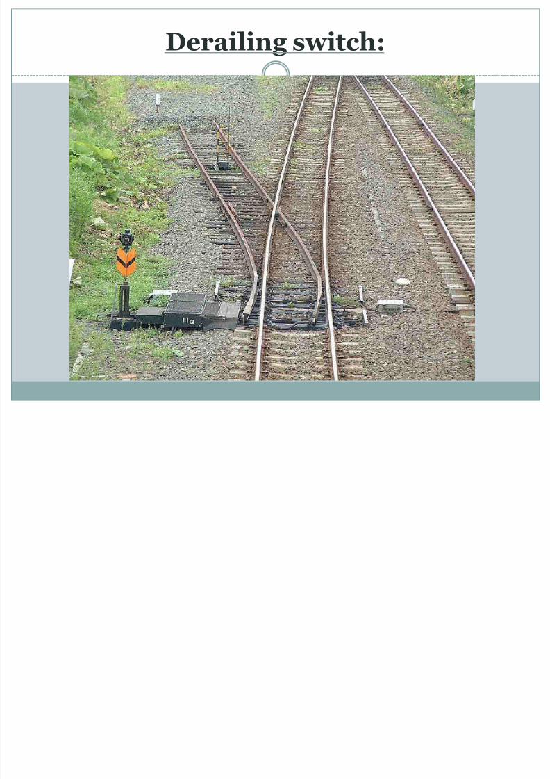
Derailing switch:
A derailing switch is an ordinary point switch The switch is open in the normal position and is
generally provided near the dead end of the siding
Any vehicle passing over it shall be derailed becauseof break of continuity of rails
8/13/2019 Unit-IV Railway Engineering
http://slidepdf.com/reader/full/unit-iv-railway-engineering 75/177
D Pit

8/13/2019 Unit-IV Railway Engineering
http://slidepdf.com/reader/full/unit-iv-railway-engineering 76/177
Drop Pits:
These are constructed at right angle to the track toexamine and repair or to replace the old wheels bynew ones.
In these pits the wheels of the locomotives arelowered and the wheels and axles are taken out withthe help of different kinds of jacks
Drop Pits:

8/13/2019 Unit-IV Railway Engineering
http://slidepdf.com/reader/full/unit-iv-railway-engineering 77/177
p
Scotch Block:

8/13/2019 Unit-IV Railway Engineering
http://slidepdf.com/reader/full/unit-iv-railway-engineering 78/177
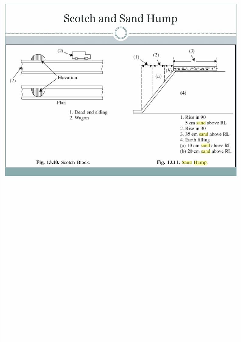
Scotch Block:
It consists of a block of wood placed on the rail andsuitably held and locked in position
It forms an obstruction to the passage of vehicles andhence it prevents the escape of vehicle beyond thedead end of the siding
Scotch Block

8/13/2019 Unit-IV Railway Engineering
http://slidepdf.com/reader/full/unit-iv-railway-engineering 79/177
Scotch Block
Scotch and Sand Hump
8/13/2019 Unit-IV Railway Engineering
http://slidepdf.com/reader/full/unit-iv-railway-engineering 80/177
Scotch and Sand Hump
Sand hump:

8/13/2019 Unit-IV Railway Engineering
http://slidepdf.com/reader/full/unit-iv-railway-engineering 81/177
Sand hump:
Method of checking vehicle The rails in the dead end siding after some fixed
distance get embedded in the sand and come to rest
Weigh Bridge:

8/13/2019 Unit-IV Railway Engineering
http://slidepdf.com/reader/full/unit-iv-railway-engineering 82/177
Weigh Bridge:
These are level platforms with rails and areconnected to the main track
The beam rests on the knife edge and attached to thelever to which loaded wagons come to the siding tothe weigh bridge is fixed
The lever mechanism is activated and weight isindicated
Weigh Bridge

8/13/2019 Unit-IV Railway Engineering
http://slidepdf.com/reader/full/unit-iv-railway-engineering 83/177
Weigh Bridge

8/13/2019 Unit-IV Railway Engineering
http://slidepdf.com/reader/full/unit-iv-railway-engineering 84/177
POINTS AND CROSSINGS

8/13/2019 Unit-IV Railway Engineering
http://slidepdf.com/reader/full/unit-iv-railway-engineering 85/177
POINTS AND CROSSINGS
Purpose for providing points and crossings: It is the name given to the arrangement which
diverts the train from one track to another, eitherparallel to or diverging from the first track.
Point and Crossings are peculiar arrangement usedin permanent way (railway track) to guide the vehiclefor directional change.
POINTS AND CROSSINGS

8/13/2019 Unit-IV Railway Engineering
http://slidepdf.com/reader/full/unit-iv-railway-engineering 86/177
Some definitions:

8/13/2019 Unit-IV Railway Engineering
http://slidepdf.com/reader/full/unit-iv-railway-engineering 87/177
Some definitions:
1.Angle of crossing: It is the angle between the running faces of point rail and
splice rail
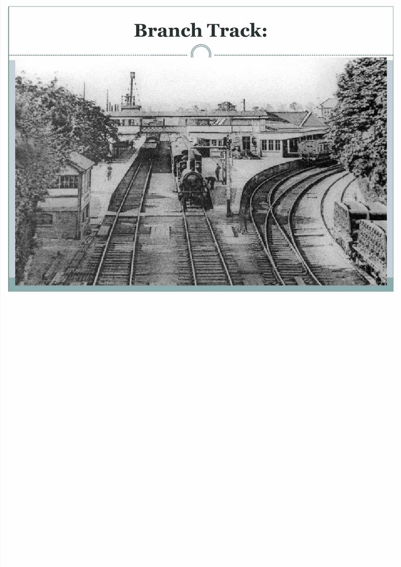
2.Branch Track:
Track to which train is diverted from main track 3.Check rails:
To prevent the tendency of wheel to climb over thecrossing rail lengths are provided on the opposite side of
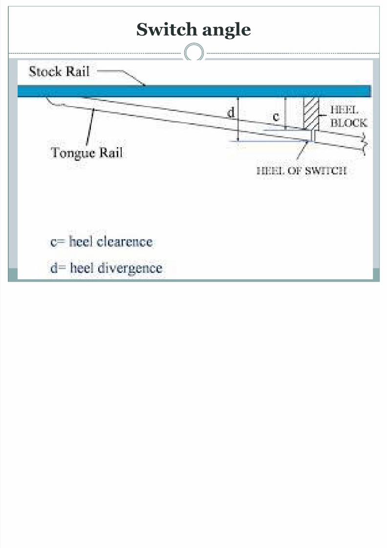
the crossing4.Heel block: It is the CI block to which tongue rail and
lead rails are both bolted
Branch Track:
8/13/2019 Unit-IV Railway Engineering
http://slidepdf.com/reader/full/unit-iv-railway-engineering 88/177
Branch Track:
Check rails

8/13/2019 Unit-IV Railway Engineering
http://slidepdf.com/reader/full/unit-iv-railway-engineering 89/177
Check rails
Heel block

8/13/2019 Unit-IV Railway Engineering
http://slidepdf.com/reader/full/unit-iv-railway-engineering 90/177
Heel block

8/13/2019 Unit-IV Railway Engineering
http://slidepdf.com/reader/full/unit-iv-railway-engineering 91/177
Lead Rails

8/13/2019 Unit-IV Railway Engineering
http://slidepdf.com/reader/full/unit-iv-railway-engineering 92/177
Lead Rails
Nose of crossing

8/13/2019 Unit-IV Railway Engineering
http://slidepdf.com/reader/full/unit-iv-railway-engineering 93/177
Nose of crossing
Tongue rail

8/13/2019 Unit-IV Railway Engineering
http://slidepdf.com/reader/full/unit-iv-railway-engineering 94/177
Tongue rail
Switch

8/13/2019 Unit-IV Railway Engineering
http://slidepdf.com/reader/full/unit-iv-railway-engineering 95/177
Switch
Throw of Switch

8/13/2019 Unit-IV Railway Engineering
http://slidepdf.com/reader/full/unit-iv-railway-engineering 96/177
Throw of Switch
8/13/2019 Unit-IV Railway Engineering
http://slidepdf.com/reader/full/unit-iv-railway-engineering 97/177
10.Switch angle: It is the angle formed between thegauge face of the stock rail and the tongue rail
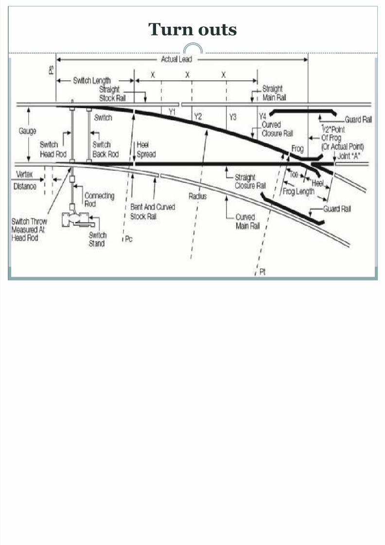
11.Turn outs: A complete set of points and crossingsalong with a lead rail is known as turnout
12. Facing direction: If someone stands at toe ofswitch and looks towards the crossing it is calledfacing direction
13.Trailing directions: If someone stands at thecrossing and looks towards the switches, then thedirection is called Trailing direction
Switch angle
8/13/2019 Unit-IV Railway Engineering
http://slidepdf.com/reader/full/unit-iv-railway-engineering 98/177
Switch angle
Turn outs
8/13/2019 Unit-IV Railway Engineering
http://slidepdf.com/reader/full/unit-iv-railway-engineering 99/177
Turn outs

8/13/2019 Unit-IV Railway Engineering
http://slidepdf.com/reader/full/unit-iv-railway-engineering 100/177
14.Facing points or Facing turn outs: When thetrain pass over the switches first and then they passover the crossing
15.Trailing points or Trailing Turnouts: The
opposite side of facing points in which the trainspass over the crossings first and then over theswitches.
Turnout

8/13/2019 Unit-IV Railway Engineering
http://slidepdf.com/reader/full/unit-iv-railway-engineering 101/177
o
Right Hand Turn out and Left Hand Turnout:

8/13/2019 Unit-IV Railway Engineering
http://slidepdf.com/reader/full/unit-iv-railway-engineering 102/177
out:
If a train from main track is diverted to the right ofthe main route in the facing direction, then thisdiversion is known as Right-hand turnouts.
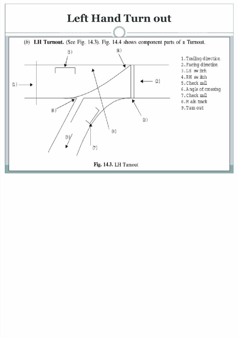
If a train from main track is diverted to the left of the
main route in the facing direction, then thisdiversion is known as Left-hand turnouts.
Right Hand Turn out

8/13/2019 Unit-IV Railway Engineering
http://slidepdf.com/reader/full/unit-iv-railway-engineering 103/177
g
Left Hand Turn out
8/13/2019 Unit-IV Railway Engineering
http://slidepdf.com/reader/full/unit-iv-railway-engineering 104/177
Sleeper Laid for Points and crossing:

8/13/2019 Unit-IV Railway Engineering
http://slidepdf.com/reader/full/unit-iv-railway-engineering 105/177
Two methods of laying sleepers below the points andcrossing
1.Through sleepers
2.Interlaced sleepers
Through sleepers and Interlaced sleepers

8/13/2019 Unit-IV Railway Engineering
http://slidepdf.com/reader/full/unit-iv-railway-engineering 106/177
g p p
1.Through sleepers:

8/13/2019 Unit-IV Railway Engineering
http://slidepdf.com/reader/full/unit-iv-railway-engineering 107/177
g p
They are provided in the overall length of points andcrossing
Through sleepers maintain several rails at the samelevel especially in straight and curved tracks.
Difficulties in the procurement and transporting oflong sleepers
Through sleepers

8/13/2019 Unit-IV Railway Engineering
http://slidepdf.com/reader/full/unit-iv-railway-engineering 108/177
g p
2.Interlaced sleepers:

8/13/2019 Unit-IV Railway Engineering
http://slidepdf.com/reader/full/unit-iv-railway-engineering 109/177
p
Adopted when longer sleepers are not available Both the tracks are laid on different sleepers, the
curved track often deforms and causes difficulties inmaintenance.
Also possess difficulties in the proper packing of the ballast
Interlaced sleepers

8/13/2019 Unit-IV Railway Engineering
http://slidepdf.com/reader/full/unit-iv-railway-engineering 110/177
p
Through sleepers and Interlaced sleepers

8/13/2019 Unit-IV Railway Engineering
http://slidepdf.com/reader/full/unit-iv-railway-engineering 111/177
Types of Switches:

8/13/2019 Unit-IV Railway Engineering
http://slidepdf.com/reader/full/unit-iv-railway-engineering 112/177
There are two types of switches(i)Stub Switch
(ii)Split Switch
(i)Stub Switch

8/13/2019 Unit-IV Railway Engineering
http://slidepdf.com/reader/full/unit-iv-railway-engineering 113/177
Earliest type of switch. No separate tongue rails are provided
Some portion of the main tracks is moved from side to side
It is obsolete now and no more in use on Indian Railways

8/13/2019 Unit-IV Railway Engineering
http://slidepdf.com/reader/full/unit-iv-railway-engineering 114/177
Crossings:

8/13/2019 Unit-IV Railway Engineering
http://slidepdf.com/reader/full/unit-iv-railway-engineering 115/177
It is a device provided at the intersection of two tailsto allow the trail moving along one of the tracks topass across the other
Types of crossing
(i)Acute crossing or Ordinary crossing
(ii)Double or obtuse crossing
(iii)Square crossing
Crossings:

8/13/2019 Unit-IV Railway Engineering
http://slidepdf.com/reader/full/unit-iv-railway-engineering 116/177
(i)Acute crossing or Ordinary crossing

8/13/2019 Unit-IV Railway Engineering
http://slidepdf.com/reader/full/unit-iv-railway-engineering 117/177
Acute angle is formed when a right hand rail of one trackcrosses left hand rail of another track at an acute angle
(ii)Double or obtuse crossing

8/13/2019 Unit-IV Railway Engineering
http://slidepdf.com/reader/full/unit-iv-railway-engineering 118/177
This crossing is fixed when a track crosses another atan obtuse angle.
(iii)Square crossing:

8/13/2019 Unit-IV Railway Engineering
http://slidepdf.com/reader/full/unit-iv-railway-engineering 119/177
When one track crosses another track of the same ordifferent gauge at right angle

8/13/2019 Unit-IV Railway Engineering
http://slidepdf.com/reader/full/unit-iv-railway-engineering 120/177
SIGNALLING:
8/13/2019 Unit-IV Railway Engineering
http://slidepdf.com/reader/full/unit-iv-railway-engineering 121/177
Objects of Signaling:

8/13/2019 Unit-IV Railway Engineering
http://slidepdf.com/reader/full/unit-iv-railway-engineering 122/177
To provide facilities for the efficient moving of trains. To ensure safety between two or more trains which
cross or approach each other's path.
To provide facilities for the maximum utility of thetrack.
To provide facilities for safe and efficient shuntingoperations.
To guide the trains movement during maintenanceand the repairs of the track.
To safeguard the trains at converging junctions andgive directional indications of diverging junctions.
Types of Signal:

8/13/2019 Unit-IV Railway Engineering
http://slidepdf.com/reader/full/unit-iv-railway-engineering 123/177
According to function According to location
Special signals

8/13/2019 Unit-IV Railway Engineering
http://slidepdf.com/reader/full/unit-iv-railway-engineering 124/177
(a)Stop signals or semaphore type signals

8/13/2019 Unit-IV Railway Engineering
http://slidepdf.com/reader/full/unit-iv-railway-engineering 125/177
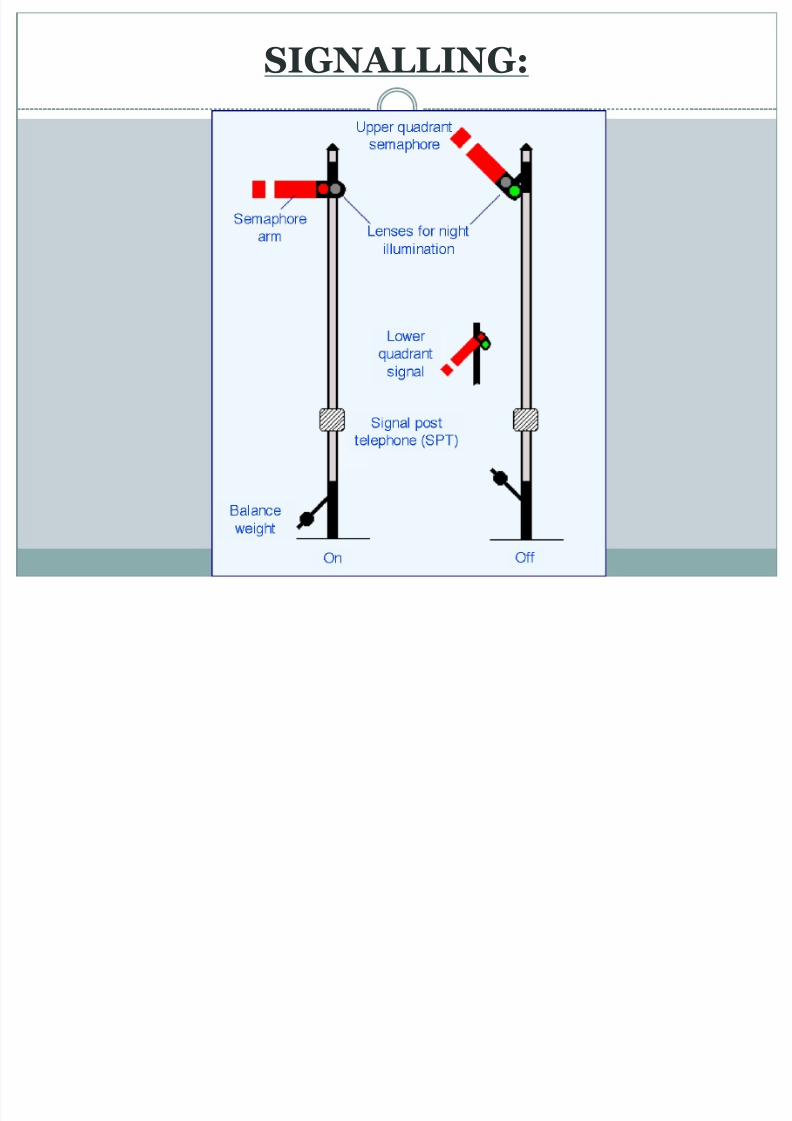
One of the earliest forms of fixed railway signal isthe semaphore.
These signals display their different indicationsto train drivers by changing the angle of inclination
of a pivoted 'arm'
The stop position is the normal position and it issaid to be ON position
The arm can be lowered at an angle of 400 to 600
with horizontal and is said to be OFF position
(a)Stop signals or semaphore type signals

8/13/2019 Unit-IV Railway Engineering
http://slidepdf.com/reader/full/unit-iv-railway-engineering 126/177
(b)Warner signals:

8/13/2019 Unit-IV Railway Engineering
http://slidepdf.com/reader/full/unit-iv-railway-engineering 127/177
The warner signal is similar to semaphore signal inshape except a v-notch at free end, ie. The movablearm is fish tailed as shown.
The white band is also of v-shape
The warner signal is placed on the same post of thesemaphore signal 1.8 to 2.1m below the semaphoresignal.
The warner signal is painted yellow and exhibits yellow or amber colour at night instead of redcolour
(b)Warner signals:

8/13/2019 Unit-IV Railway Engineering
http://slidepdf.com/reader/full/unit-iv-railway-engineering 128/177
Shunting Signals:
8/13/2019 Unit-IV Railway Engineering
http://slidepdf.com/reader/full/unit-iv-railway-engineering 129/177
These signals are used for shunting operations instation yards They are of the shape of a circular disc with a red
band on a white back ground The disc can revolve in a vertical plane by pulling
the lever by hand. Two holes are provided, one for red lamp and the
other for the green lamp. When the red band is horizontal or shows red light
at night it indicates ―STOP‖ When the red band is inclined at 45 degree or
shown green light at night indicates ―PROCEED‖
Shunting Signals:

8/13/2019 Unit-IV Railway Engineering
http://slidepdf.com/reader/full/unit-iv-railway-engineering 130/177
Shunting Signals:

8/13/2019 Unit-IV Railway Engineering
http://slidepdf.com/reader/full/unit-iv-railway-engineering 131/177
Colour light signals:

8/13/2019 Unit-IV Railway Engineering
http://slidepdf.com/reader/full/unit-iv-railway-engineering 132/177
Semaphore signals are being replaced by highintensity beam colour light signals both during dayand night
In case of colour light signals, the normal position
is to indicate ―PROCEED‖ (ie., shows green light)
When the section is blocked, it automaticallyindicates ―STOP‖ or ―DANGER‖ (ie., shows red
light) In India these signals are used on urban and sub-
urban sections with heavy traffic
Colour light signals:

8/13/2019 Unit-IV Railway Engineering
http://slidepdf.com/reader/full/unit-iv-railway-engineering 133/177
Colour light signals

8/13/2019 Unit-IV Railway Engineering
http://slidepdf.com/reader/full/unit-iv-railway-engineering 134/177
Locational characteristics

8/13/2019 Unit-IV Railway Engineering
http://slidepdf.com/reader/full/unit-iv-railway-engineering 135/177
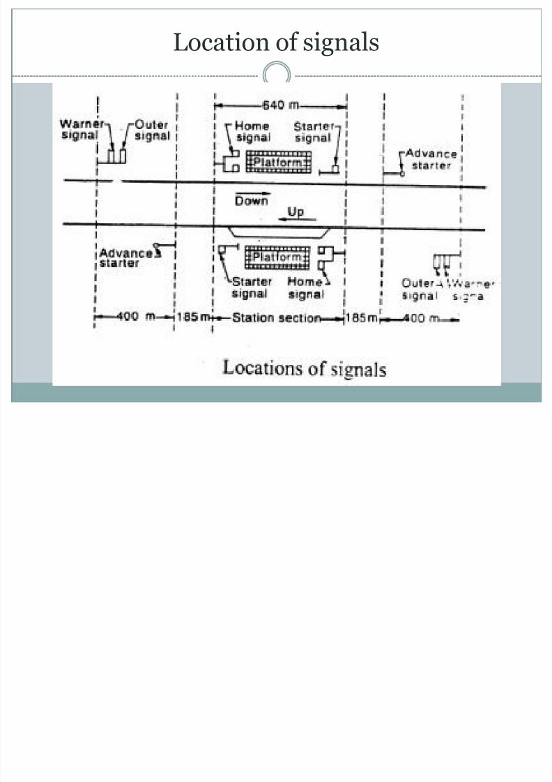
(i)Reception signals (a)Outer signal
(b)Home signal
(ii) Departure signals
(a)Starter
(b)Advance Starter
Location of signals
8/13/2019 Unit-IV Railway Engineering
http://slidepdf.com/reader/full/unit-iv-railway-engineering 136/177
(a)Outer signal:

8/13/2019 Unit-IV Railway Engineering
http://slidepdf.com/reader/full/unit-iv-railway-engineering 137/177
This is the first stop signal which indicates the entry ofthe train from block to the station yard
It should be placed at an adequate distance (0.54km forBG and 0.4 km for MG)
It has one arm but may have a warner signal on the samepost nearly 2m below it.
In the Stop position the driver must bring his train to astop at a distance of about 90m before the outer signaland then proceed to the home signal with caution
If it is in the Proceed position then the driver can takethe train at speed, assuming that home signal is also inthe proceed position.
(b)Home signal:

8/13/2019 Unit-IV Railway Engineering
http://slidepdf.com/reader/full/unit-iv-railway-engineering 138/177
Due to its location at the door of station, it istermed as Home signal.
The home signal has bracketed arms to indicate which line is to be used.
The function of home signal is to protect thesidings already occupied.
It is located at not more than 180m from the start
of points of switches. Home signals carry as many arms as the number of
diverging lines.
(c)Starter signals:

8/13/2019 Unit-IV Railway Engineering
http://slidepdf.com/reader/full/unit-iv-railway-engineering 139/177
It marks the limit up to which trains stopping at astation should come to a stand
The starter is the last stop signal at a station
It controls the movements of the trains when theydepart from the stations.
No train can leave the station unless the startersignal shows the ―PROCEED‖ position (ie.,
inclined position)
(d)Advance Starter signals:

8/13/2019 Unit-IV Railway Engineering
http://slidepdf.com/reader/full/unit-iv-railway-engineering 140/177
Besides the starter signal for each of the stationlines from which trains starts, an advance startermay also be provided.
The advance starter becomes the last stop signal at
the stations where is provided.
It is an indication for the train having left thestation
Special Signals:
8/13/2019 Unit-IV Railway Engineering
http://slidepdf.com/reader/full/unit-iv-railway-engineering 141/177
(i)Repeater or Co-acting signal:
When a train passes through a station withoutstopping, the driver comes across the five signals inthis sequence WARNER, OUTER, HOME, STARTERand ADVANCE STARTER.
When the drivers vision is obstructed by an over bridge between the signals, a signal is provided witha duplicate arm of smaller size at a suitable position which repeats the indication of signal head. It istherefore termed as Repeater signal.
This signal is linked with the main signal andtherefore, when the lever is pulled both signals arelowered simultaneously. Also called as ―co-actingsignal‖
Repeater or Co-acting Signal

8/13/2019 Unit-IV Railway Engineering
http://slidepdf.com/reader/full/unit-iv-railway-engineering 142/177
(ii)Routing Signal:

8/13/2019 Unit-IV Railway Engineering
http://slidepdf.com/reader/full/unit-iv-railway-engineering 143/177
When various signals for main and branch lines arefixed on the same vertical post, they are known asrouting signals.
Generally the signal for the main line is kept at
higher level than that for branch line.
(ii)Routing Signal:

8/13/2019 Unit-IV Railway Engineering
http://slidepdf.com/reader/full/unit-iv-railway-engineering 144/177
(iii)Calling-on Signal:

8/13/2019 Unit-IV Railway Engineering
http://slidepdf.com/reader/full/unit-iv-railway-engineering 145/177
These consist of small and short arms fixed on thesame post below main signals
A calling-on signal permits a train to proceedcautiously after the train has been brought to a halt
by the main signal This signals are helpful when repair works are going
on
Calling-on Signal

8/13/2019 Unit-IV Railway Engineering
http://slidepdf.com/reader/full/unit-iv-railway-engineering 146/177
(iv)Miscellaneous signals:

8/13/2019 Unit-IV Railway Engineering
http://slidepdf.com/reader/full/unit-iv-railway-engineering 147/177
Various other devices are used for indicating signals.Signals are meant for goods sidings are distinguished by providing rings or writing capital letter S etc.,
Two crossed bars are put up on the signal which is
under repair and it is placed in ON position.

8/13/2019 Unit-IV Railway Engineering
http://slidepdf.com/reader/full/unit-iv-railway-engineering 148/177
(i)Following trains system:

8/13/2019 Unit-IV Railway Engineering
http://slidepdf.com/reader/full/unit-iv-railway-engineering 149/177
Used in case of emergencies such as failure oftelegraph and telephone systems.
In this method, a fixed interval of time is maintained between the departure of one train and the departure
of the next train along the same time. This fixed interval is worked out in such a way that
sufficient distance or headway in maintained between the tail of the first train and the head of the
next following train.
(ii)Absolute block system:
8/13/2019 Unit-IV Railway Engineering
http://slidepdf.com/reader/full/unit-iv-railway-engineering 150/177
The principle of the absolute block system of railwaysignalling is to ensure the safe operation of a railway byallowing only one train to occupy a defined section of track ata time
Instead of a fixed interval of time between successive trains, a varying interval may be kept depending on the time, actually
taken by particular trains. It is a space interval system rather than a fixed interval
system. In the absolute block system the line is assumed to be blocked
until the fact that the line is clear is established by some
suitable information conveyed by block instruments The electric telegraph provided the ability for signalmen to
communicate with each other and provided the basis for theabsolute block system
Absolute Block Diagram

8/13/2019 Unit-IV Railway Engineering
http://slidepdf.com/reader/full/unit-iv-railway-engineering 151/177
(iii)Automatic signaling:

8/13/2019 Unit-IV Railway Engineering
http://slidepdf.com/reader/full/unit-iv-railway-engineering 152/177
In order to avoid accidents, automaticsignalling has been found out. In this signalsare operated by trains themselves.
An electric current is conveyed through thetrack when a train occupies that particulartrack and this current puts the signal atdanger position until the train has gone farahead so as to require no further protection
(iv)Pilot guard system:

8/13/2019 Unit-IV Railway Engineering
http://slidepdf.com/reader/full/unit-iv-railway-engineering 153/177
Used on certain occasions such as breakdown of telephone and telegraphsystem on a single line and one track of a
double line being out of order. In this system, a pilot proceeds by one train
to the station ahead and then he returns by atrain running in the opposite direction.
Centralized Traffic Control:

8/13/2019 Unit-IV Railway Engineering
http://slidepdf.com/reader/full/unit-iv-railway-engineering 154/177
Centralized traffic control (CTC) is a formof railway signalling that originated in North America
The system consists of a centralized train dispatcher'soffice that controls railroad switches in the CTC
territory and the signals that railroad engineers mustobey in order to keep the traffic moving safely andsmoothly across the railroad.
CTC systems are considered sufficient authority to
run trains based strictly on signal indications. This is because CTC signals default to 'Stop' and require ahuman dispatcher to 'Clear' them.
Centralized Traffic Control

8/13/2019 Unit-IV Railway Engineering
http://slidepdf.com/reader/full/unit-iv-railway-engineering 155/177
Interlocking:

8/13/2019 Unit-IV Railway Engineering
http://slidepdf.com/reader/full/unit-iv-railway-engineering 156/177
Definition:
In railway signalling, an interlocking is an arrangement ofsignal apparatus that prevents conflicting movements throughan arrangement of tracks such as junctions or crossings
An arrangement of signals and signal appliances sointerconnected that their movements must succeed each
other in proper sequence". In general terms an interlocking is a location where plain
track ends and trackwork with points and crossingscomplicate train movements. These areas are likely to be:- Junctions where two or more main lines meet.
Complex yards or sidings are encountered. These may be at larger townsor depot facilities.
An interlocking provides for complex train movements andshunting of trains.
It provides for the protection of multiple train movements within a localised area.
Principles of Interlocking:

8/13/2019 Unit-IV Railway Engineering
http://slidepdf.com/reader/full/unit-iv-railway-engineering 157/177
Not possible to lower the signals for the admissions oftrains from opposite direction or converging directions atthe same time to the same line
Not possible to lower a signal for any approaching trainuntil the correct points
Not possible for loose wagons from any part of the yard toobstruct the line which is set for incoming train afterlowering the signal
When the signal is lowered, it should not be possible to
disconnect any point or reverse unlock the points until thetrain has passed and signals have been raised to its ―ON‖position.
Not possible to lower warner signal unless home andstarting signals have lowered in advance
Methods of Interlocking:

8/13/2019 Unit-IV Railway Engineering
http://slidepdf.com/reader/full/unit-iv-railway-engineering 158/177
The signals and points are operated by means oflevers.
Levers are located at ground level or platform level orin an elevated structure called signal box or signalcabin
Interlocking is done by grouping levers at one point
The levers are painted for easy identification
There are three methods of interlocking
(i)Tappets and lock system (ii)Key system
(iii)Route relay system.
(i)Tappets and lock system

8/13/2019 Unit-IV Railway Engineering
http://slidepdf.com/reader/full/unit-iv-railway-engineering 159/177
This method is useful when levers are to beinterlocked so as to prevent conflicting movement
The tappers are of steel sections. 38mmX16mm withsuitable recesses and notches.
They are attached to the levers.
The locks are also of steel with shapes to suit therecesses in the tappers.
The lock move at right angle to the tappers
Working of Tappets and locks system:

8/13/2019 Unit-IV Railway Engineering
http://slidepdf.com/reader/full/unit-iv-railway-engineering 160/177
The normal setting of the points is for the main line.The signal for the main line should be interlocked with the facing points so that when it is lowered,points cannot be changed. The levers are interlocked
such that pulling one of them prevents the other being pulled. This is known as (1) locks (3)

8/13/2019 Unit-IV Railway Engineering
http://slidepdf.com/reader/full/unit-iv-railway-engineering 161/177
The loop signal should be interlocked with the facingpoints such that it cannot be lowered unless the points areset for the siding. Also it cannot be lowered when the
joints are set for main line. Levers (2) and (3) areinterlocked so that the lever (2) cannot be pulled unless(3) has already been pulled.
Conversely lever (3) can be restored to its normal positiononly if lever (2) has already been restored to its originalposition. This is known as (3) release (2) or (2) back locks(3)
The outer signal should be so interlocked with the routingsignal that it cannot be lowered until one of them is firstlowered. When levers (1), (2) and (4) are interlocked sothat lever (4) cannot be worked unless lever (1) or (2) hasalready been worked

8/13/2019 Unit-IV Railway Engineering
http://slidepdf.com/reader/full/unit-iv-railway-engineering 162/177
The working of this system is given in theinterlocking table below
Descriptio
n of levers
Lever
No.
Releas
e
Lock
s
Backloc
ks
Main 1 4 3 -
Loop 2 4 - 3Points 3 2 1 -
Outer 4 - - 1,2
Tappet & Locks System

8/13/2019 Unit-IV Railway Engineering
http://slidepdf.com/reader/full/unit-iv-railway-engineering 163/177
Tappet & Locks System

8/13/2019 Unit-IV Railway Engineering
http://slidepdf.com/reader/full/unit-iv-railway-engineering 164/177
Key System:

8/13/2019 Unit-IV Railway Engineering
http://slidepdf.com/reader/full/unit-iv-railway-engineering 165/177
This is the simplest method of interlocking. The key locks
are manipulated in this systemSingle lock and key system: The principle of this system is to provide two locks which
are worked by a single key. With drawl of the key locksthe signal in the horizontal position and the points in the
normal setting for the main line. And B are two locksoperated by a single key. To lower the signal the key isinserted and turned in the lock B. This releases the signaland when the signal is lowered, it prevents the key from
being withdrawn. Hence when the signal is lowered the
point is correctly set for the main line. For using thesiding, the key withdrawn from the lock B after restoringsignal from normal position and inserted and turned inlock A. This releases the points which may then be set forsiding. Now the main signal cannot be lowered.
Route relay System:

8/13/2019 Unit-IV Railway Engineering
http://slidepdf.com/reader/full/unit-iv-railway-engineering 166/177
In this system, the points and signals for movementsof trains are electrically operated. This is the modeand sophisticated system of interlocking. Due to thissystem there is a considerable saving of man power
and maintenance expenditure of cabins.
Route relay System

8/13/2019 Unit-IV Railway Engineering
http://slidepdf.com/reader/full/unit-iv-railway-engineering 167/177
Rapid Transport System:

8/13/2019 Unit-IV Railway Engineering
http://slidepdf.com/reader/full/unit-iv-railway-engineering 168/177
General
Rapid transport is a type of high-capacity publictransport generally found in urban areas.
Unlike buses and trains, rapid transport systems operateon an exclusive right-of-way which is usually grade
separated in tunnels or elevated railways. Metro is the most common term for underground rapid
transport systems
Rapid transport is used in cities, agglomerations,
and metropolitan areas to transport large numbers ofpeople often short distances at high frequency . The extentof the rapid transport system varies greatly betweencities, with several transport strategies
Elevated railways

8/13/2019 Unit-IV Railway Engineering
http://slidepdf.com/reader/full/unit-iv-railway-engineering 169/177
Mono Rail

8/13/2019 Unit-IV Railway Engineering
http://slidepdf.com/reader/full/unit-iv-railway-engineering 170/177
Metro Rail in Chennai

8/13/2019 Unit-IV Railway Engineering
http://slidepdf.com/reader/full/unit-iv-railway-engineering 171/177

8/13/2019 Unit-IV Railway Engineering
http://slidepdf.com/reader/full/unit-iv-railway-engineering 172/177
Under ground railways:

8/13/2019 Unit-IV Railway Engineering
http://slidepdf.com/reader/full/unit-iv-railway-engineering 173/177
Advantages :
This system provides rapid and unobstructedtransportation.
This system helps in reducing traffic congestion
problems. This system provides safety during aerial attack in
war.
Suitability :
Underground railways are suitable in the heavilycongested urban areas where the traffic intensity onroads is heavy.
Under ground railways

8/13/2019 Unit-IV Railway Engineering
http://slidepdf.com/reader/full/unit-iv-railway-engineering 174/177
Tube railways :

8/13/2019 Unit-IV Railway Engineering
http://slidepdf.com/reader/full/unit-iv-railway-engineering 175/177
The railway provided underground at a greaterdepth of about 18 m or more (up to 52 m) are calledtube railways.
This system of railways is so called as the section of
the underground tunnels, carrying the track, is toavoid the interference of the tracks with water andgas pipes, sewerage systems and oil or drainage
pipes, etc
An electrically powered railroad with tracks runningthrough a tunnel underground; a subway.
Some important features of the tube railways aregiven below :-

8/13/2019 Unit-IV Railway Engineering
http://slidepdf.com/reader/full/unit-iv-railway-engineering 176/177
The railways stations have to be of cylindrical form.
Escalators or moving stair cases are to be constructedto reach the tube railways.
Only electric traction to be used to avoid the smoke
and ventilation problems. Automatic signaling system is to be used.
Such a mechanism of the train is to be used that itcannot start until all the doors are closed, and it
automatically stops, if the signal is at ‗STOP‘ position. This system of railways is used by the London Post
Office in transporting mails through a small diametertunnel with automatic control without any driver.
Tube railways :

8/13/2019 Unit-IV Railway Engineering
http://slidepdf.com/reader/full/unit-iv-railway-engineering 177/177


