Unit IV Drawing of rods, wires and tubes Introduction YEAR/METAL FORMING PROCESSES/Unit 4.pdfDrawing...
13
1 Unit –IV Drawing of rods, wires and tubes Introduction Drawing is a process in which the material is pulled through a die by means of a tensile force. Usually the constant cross section is circular (bar, rod, wire, tube). Fig Drawing process Metal Drawing Process The metal drawing process in manufacturing industry is usually performed cold. Cold working will impart the drawn product with accurate tolerances, favorable grain structure, improved material properties and good surface finish. Preparation of the work, prior to drawing, is an important part of the operation. The work is sometimes annealed first, to recover the material from existing stresses. Next the work surfaces are cleaned. Common industrial practice for cleaning metal stock includes shot blasting or submersion in some, (typically acidic), solution. Metal drawing can be either a discrete or continuous operation and can be very economically efficient for certain applications. In commercial industry, this process provides stock material for machining operations and for the manufacture of such items as fences, coat hangers, nails, screws and bolts. Metal wire drawing plays a huge roll in the manufacturing industry in the production of cable and electrical wire. Drawing Dies Metal drawing dies, in manufacturing industry, are usually made of cemented carbides or tool steels. Mandrels for tube drawing are often made of similar materials as the die. Occasionally diamond die are employed to form extremely thin wire. As the work transverses the mold it passes through different sections. The die's first section is a bell curved opening. This area does not contact the work, but helps filter lubricant into the mold and allows for adequate entry of the work into the mold without damage from die edges.
Transcript of Unit IV Drawing of rods, wires and tubes Introduction YEAR/METAL FORMING PROCESSES/Unit 4.pdfDrawing...
1
Unit –IV
Drawing of rods, wires and tubes
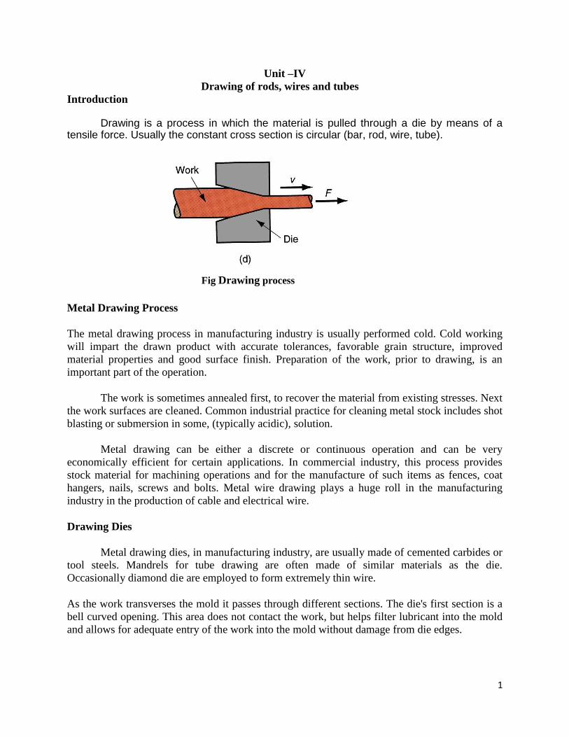
Introduction Drawing is a process in which the material is pulled through a die by means of a
tensile force. Usually the constant cross section is circular (bar, rod, wire, tube).
Fig Drawing process
Metal Drawing Process
The metal drawing process in manufacturing industry is usually performed cold. Cold working
will impart the drawn product with accurate tolerances, favorable grain structure, improved
material properties and good surface finish. Preparation of the work, prior to drawing, is an
important part of the operation.
The work is sometimes annealed first, to recover the material from existing stresses. Next
the work surfaces are cleaned. Common industrial practice for cleaning metal stock includes shot
blasting or submersion in some, (typically acidic), solution.
Metal drawing can be either a discrete or continuous operation and can be very
economically efficient for certain applications. In commercial industry, this process provides
stock material for machining operations and for the manufacture of such items as fences, coat
hangers, nails, screws and bolts. Metal wire drawing plays a huge roll in the manufacturing
industry in the production of cable and electrical wire.
Drawing Dies
Metal drawing dies, in manufacturing industry, are usually made of cemented carbides or
tool steels. Mandrels for tube drawing are often made of similar materials as the die.
Occasionally diamond die are employed to form extremely thin wire.
As the work transverses the mold it passes through different sections. The die's first section is a
bell curved opening. This area does not contact the work, but helps filter lubricant into the mold
and allows for adequate entry of the work into the mold without damage from die edges.

2
Next, the forming of the work occurs in the approach section. The approach angles down
the cross sectional area, connecting with the next section, the bearing surface. Bearing surface,
also known as land, holds the precise geometric cross section for a length of the draw. This acts
as a sizing operation, ensuring tight tolerances. The last section is the exit zone, this is a steeply
angled section similar to the entry zone. Exit zones are used to protect drawn work from the
edges of the die.
Defects In Metal Drawing:
Defects that occur in metal drawing manufacture are similar to those that occur while
manufacturing by extrusion. Controlling metal flow is essential in preventing defects. Mold
characteristics and friction play a critical roll in the process.
Internal Cracking: Internal breakage may occur in drawn products, particularly along the
centerline. This is due to improper metal flow creating high internal stresses. Causes may be high
die angles or low friction.
Surface Defect: A wide variety of surface defects can be observed in metal drawing
manufacture. Seams, scratches and cracks are all possible defects on the surface of drawn
product. Excessive force on the surface of the work during the drawing operation, (such as from
friction), can be the cause of breakage. Also, many metal drawing operations form at very high
speeds, sufficiently designed entry and exit zones need to be provided in order to avoid damage
to the work material from the die. For more detailed information on internal breakage and
surface defects see extrusion defects.
Rod and Bar Drawing
Rod or bar drawing is a term used to denote one of two categories of metal drawing. Rod or bar
drawing refers to the drawing of work of larger cross sections, while wire drawing refers to the
forming of work of a relatively smaller profile. Due to the size of the work, rod and bar drawing

3
involves much more finite lengths of material than wire drawing. This type of process is carried
out as a discrete manufacturing operation.
Rod or bar drawing is usually performed on a draw bench. A draw bench consists of a long table,
a die stand containing the mold and a carriage used to grip and draw the work. The die stand may
contain two or more molds; multiple dies allow more than one part to be drawn with each
operation. Draw benches vary in size and can be up to 100 feet in length. Force used to draw the
metal is exerted through hydraulic or mechanical means. Pulling force as high as 150 tons has
been used during industrial production.
Production of Hollow Tubes and Drawn Shapes
The majority of metal drawing operations produce round or square shapes, however different
cross sections such as u-sections and other simple shapes are also manufactured. Hollow profiles,
particularly hollow round tubes of different lengths, diameters and wall thicknesses are common
in drawing production. Many tubes and special profiles are of larger geometry, and are drawn as
a discrete manufacturing operation. Production of drawn shapes and hollow tubes is usually
performed on a draw bench and would be classified in the rod and bar category of operations.
4
The specifics of the metal deformation are important when drawing different cross sections.
Sometimes a series of operations may be needed to form a particular profile.
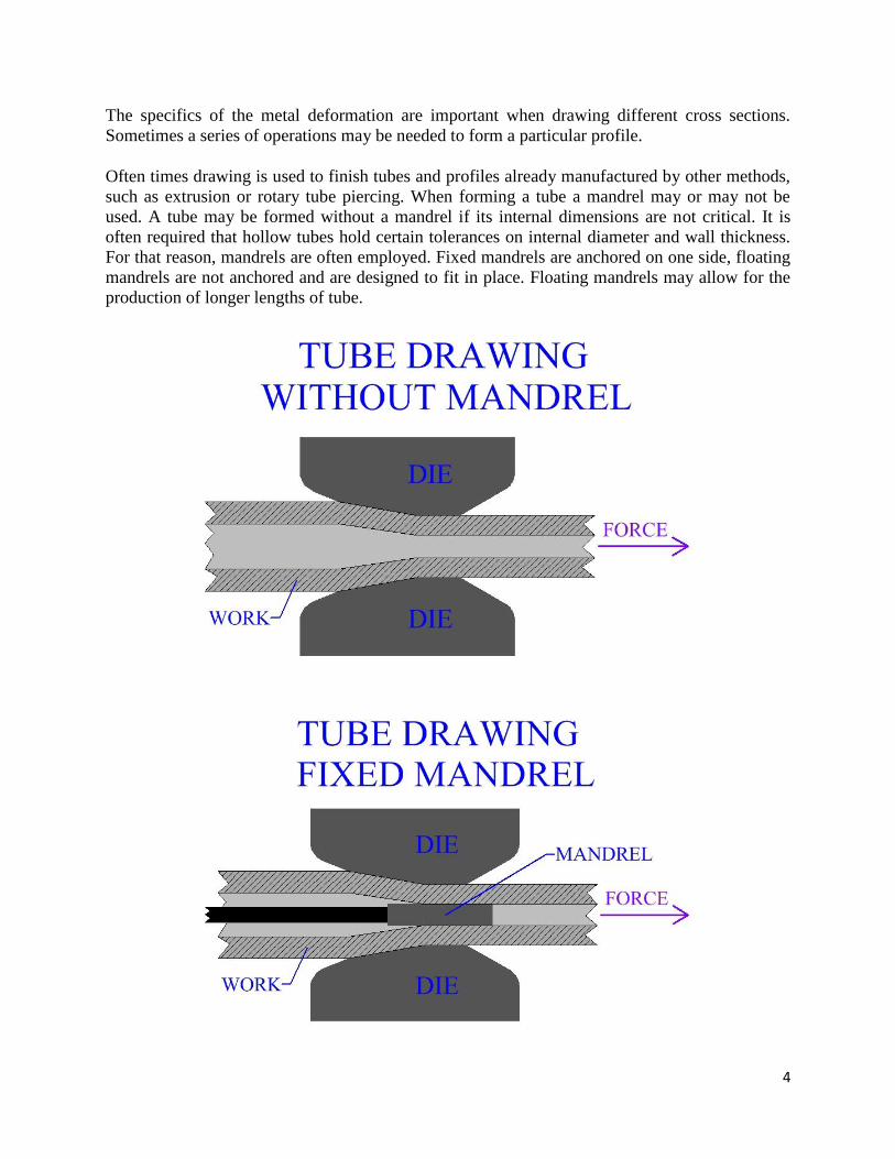
Often times drawing is used to finish tubes and profiles already manufactured by other methods,
such as extrusion or rotary tube piercing. When forming a tube a mandrel may or may not be
used. A tube may be formed without a mandrel if its internal dimensions are not critical. It is
often required that hollow tubes hold certain tolerances on internal diameter and wall thickness.
For that reason, mandrels are often employed. Fixed mandrels are anchored on one side, floating
mandrels are not anchored and are designed to fit in place. Floating mandrels may allow for the
production of longer lengths of tube.

5
Figure:
Wire Drawing
Wire drawing is the second major category of metal drawing operations. While rod and
bar drawing refer to the drawing of larger cross sections, wire drawing refers to the drawing of
relatively smaller cross sections.
The enormous amount of electrical wire and cable produced by this manufacturing
method makes wire drawing a major modern industrial process. Some wire must be
manufactured to tremendously small cross sectional areas, such as those used in electromagnets.
Wire may be drawn to diameters as low as .0001 inch. Diamond die inserts are often used in the
production of extremely fine wire.
Metal work stock in wire drawing will usually undergo several reductions in diameter,
since the mechanics of the process limit the amount of reduction in a single draw.

6
This is accomplished by drawing the work through several die in series, each producing
an incremental reduction in the work's diameter. Between dies the wire stock is wrapped several
times around a motor driven rotating drum called a capstan, before proceeding to the next die in
series.
Annealing of the metal may be performed between groups of operations. The capstans
provide the force for the manufacturing process. As the diameter is reduced, the speed of the
wire is increased. Velocity of wire leaving the last mold in a series can be significantly higher
than the velocity of the work entering the first mold. Typically drawing speeds may be 20-100
feet per minute, but in some cases wire may be drawn at 10,000 feet per minute. Pieces of stock
can be end welded together as they are fed into the system of capstans and die so that the process
will be completely continuous. Industrial wire drawing operations can manufacture miles of wire
at a time.
Figure:

7
Sheet metal forming;
Sheet metal forming processes are those in which force is applied to a piece of sheet metal to
modify its geometry rather than remove any material.
The applied force stresses the metal beyond its yield strength, causing the material to
plastically deform, but not to fail. By doing so, the sheet can be bent or stretched into a variety of
complex shapes. Sheet metal forming processes include the following:
Bending
Roll forming
Spinning
Deep Drawing
Stretch forming
Bending
Bending is a metal forming process in which a force is applied to a piece of sheet metal,
causing it to bend at an angle and form the desired shape. A bending operation causes
deformation along one axis, but a sequence of several different operations can be performed to
create a complex part. Bent parts can be quite small, such as a bracket, or up to 20 feet in length,
such as a large enclosure or chassis. A bend can be characterized by several different parameters,
shown in the image below.
Bending Diagram
Bend line - The straight line on the surface of the sheet, on either side of the bend, that
defines the end of the level flange and the start of the bend.
Outside mold line - The straight line where the outside surfaces of the two flanges would
meet, were they to continue. This line defines the edge of a mold that would bound the bent
sheet metal.
Flange length - The length of either of the two flanges, extending from the edge of the sheet
to the bend line.
Mold line distance - The distance from either end of the sheet to the outside mold line.

8
Setback - The distance from either bend line to the outside mold line. Also equal to the
difference between the mold line distance and the flange length.
Bend axis - The straight line that defines the center around which the sheet metal is bent.
Bend length - The length of the bend, measured along the bend axis.
Bend radius - The distance from the bend axis to the inside surface of the material, between
the bend lines. Sometimes specified as the inside bend radius. The outside bend radius is
equal to the inside bend radius plus the sheet thickness.
Bend angle - The angle of the bend, measured between the bent flange and its original
position, or as the included angle between perpendicular lines drawn from the bend lines.
Bevel angle - The complimentary angle to the bend angle.
‘V’ type of Bending
Wipe bending
Shearing and Blanking (Separation of the materials by two cutting edges)

9
Stretching (Forming by tensile stresses over a tool)
Spinning (Forming against a rotating form block with a tool)
Spinning, sometimes called spin forming, is a metal forming process used to form
cylindrical parts by rotating a piece of sheet metal while forces are applied to one side. A sheet
metal disc is rotated at high speeds while rollers press the sheet against a tool, called a mandrel,
to form the shape of the desired part. Spun metal parts have a rotationally symmetric, hollow
shape, such as a cylinder, cone, or hemisphere. Examples include cookware, hubcaps, satellite
dishes, rocket nose cones, and musical instruments.
Deep drawing
Deep drawing is a metal forming process in which sheet metal is stretched into the desired part
shape. A tool pushes downward on the sheet metal, forcing it into a die cavity in the shape of the
desired part.
The tensile forces applied to the sheet cause it to plastically deform into a cup-shaped part. Deep
drawn parts are characterized by a depth equal to more than half of the diameter of the part.
These parts can have a variety of cross sections with straight, tapered, or even curved walls, but
cylindrical or rectangular parts are most common. Deep drawing is most effective with ductile
metals, such as aluminum, brass, copper, and mild steel.
Examples of parts formed with deep drawing include automotive bodies and fuel tanks, cans,
cups, kitchen sinks, and pots and pans.
The deep drawing process requires a blank, blank holder, punch, and die. The blank is a piece of
sheet metal, typically a disc or rectangle, which is pre-cut from stock material and will be formed

10
into the part. The blank is clamped down by the blank holder over the die, which has a cavity in
the external shape of the part.
A tool called a punch moves downward into the blank and draws, or stretches, the material into
the die cavity. The movement of the punch is usually hydraulically powered to apply enough
force to the blank. Both the die and punch experience wear from the forces applied to the sheet
metal and are therefore made from tool steel or carbon steel.
The process of drawing the part sometimes occurs in a series of operations, called draw
reductions. In each step, a punch forces the part into a different die, stretching the part to a
greater depth each time. After a part is completely drawn, the punch and blank holder can be
raised and the part removed from the die. The portion of the sheet metal that was clamped under
the blank holder may form a flange around the part that can be trimmed off.
Deep Drawing
Deep Drawing Sequence

11
Stretch forming
Stretch forming is a metal forming process in which a piece of sheet metal is stretched
and bent simultaneously over a die in order to form large contoured parts.
Stretch forming is performed on a stretch press, in which a piece of sheet metal is
securely gripped along its edges by gripping jaws. The gripping jaws are each attached to a
carriage that is pulled by pneumatic or hydraulic force to stretch the sheet.
The tooling used in this process is a stretch form block, called a form die, which is a solid
contoured piece against which the sheet metal will be pressed. The most common stretch presses
are oriented vertically, in which the form die rests on a press table that can be raised into the
sheet by a hydraulic ram.
As the form die is driven into the sheet, which is gripped tightly at its edges, the tensile
forces increase and the sheet plastically deforms into a new shape. Horizontal stretch presses
mount the form die sideways on a stationary press table, while the gripping jaws pull the sheet
horizontally around the form die.
Stretch Forming
Stretch formed parts are typically large and possess large radius bends. The shapes that can be
produced vary from a simple curved surface to complex non-uniform cross sections. Stretch
forming is capable of shaping parts with very high accuracy and smooth surfaces.
Ductile materials are preferable, the most commonly used being aluminum, steel, and titanium.
Typical stretch formed parts are large curved panels such as door panels in cars or wing panels
on aircraft. Other stretch formed parts can be found in window frames and enclosures.
Blanking and piercing
Blanking and piercing are shearing processes in which a punch and die are used to modify webs.
The tooling and processes are the same between the two, only the terminology is different: in

12
blanking the punched out piece is used and called a blank; in piercing the punched out piece is
scrap. The process for parts manufactured simultaneously with both techniques is often termed
"pierce and blank." An alternative name of piercing is punching.
Rubber pad forming
The rubber pad forming technology, the alternative for deep drawing in small series
Rubber pad forming is a sheet metal forming process in which a rubber pad is used to
form sheet metal. Due to the material properties of the rubber, the pad will regain its
original shape when retracted from the tool.
The great advantage is that only one tool is needed, the rubber takes over the function of
the counter die and the blank holder. This results in low tooling costs, a short time to
market and minimal damage of the material surface. An important additional operation
within the process is 3D cutting of the product with a CNC driven 3D laser cutting
machine.
A metal sheet is positioned on a one sided tool.
A steel casing containing a rubber pad is pressed down over or in the tooling (one
sided die) .
13
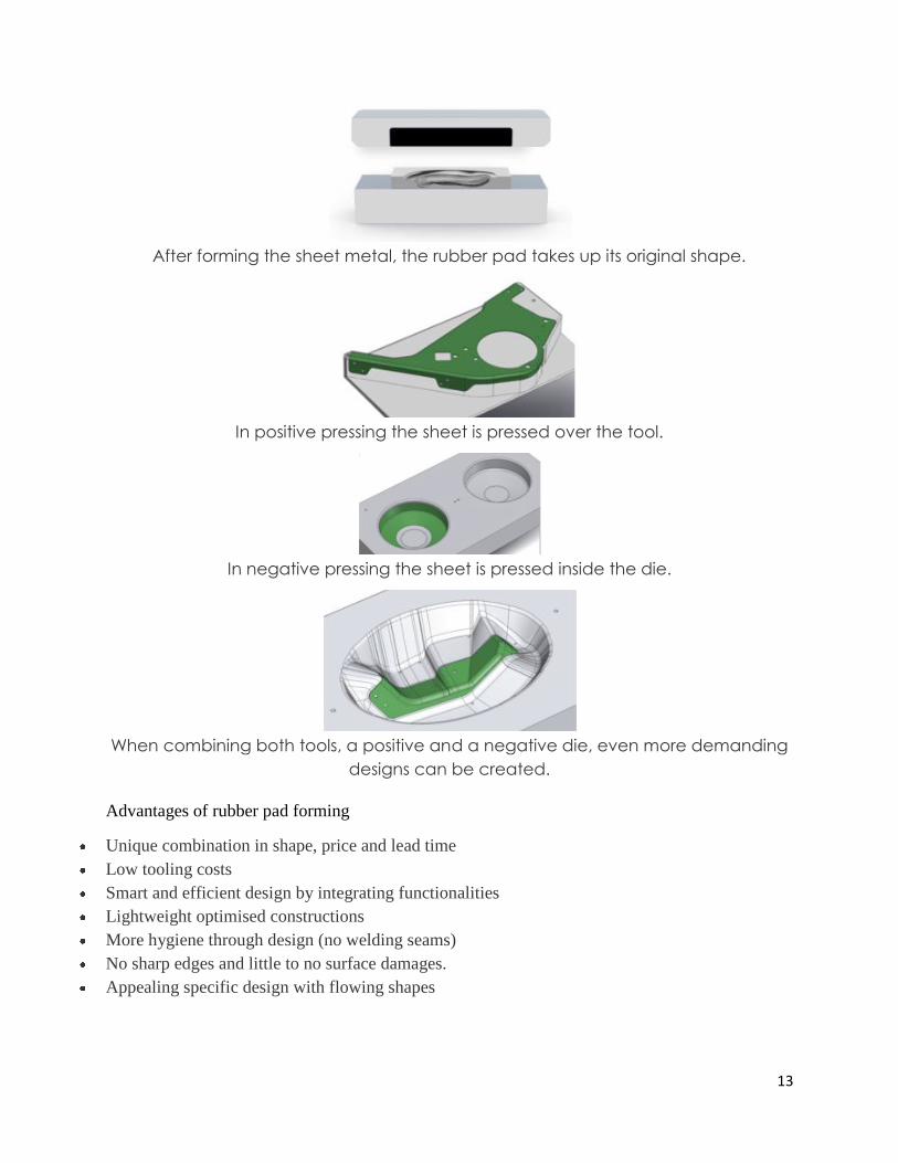
After forming the sheet metal, the rubber pad takes up its original shape.
In positive pressing the sheet is pressed over the tool.
In negative pressing the sheet is pressed inside the die.
When combining both tools, a positive and a negative die, even more demanding
designs can be created.
Advantages of rubber pad forming
Unique combination in shape, price and lead time
Low tooling costs
Smart and efficient design by integrating functionalities
Lightweight optimised constructions
More hygiene through design (no welding seams)
No sharp edges and little to no surface damages.
Appealing specific design with flowing shapes