WIRE DRAWING - Mechatronics Engineering Department -...
21
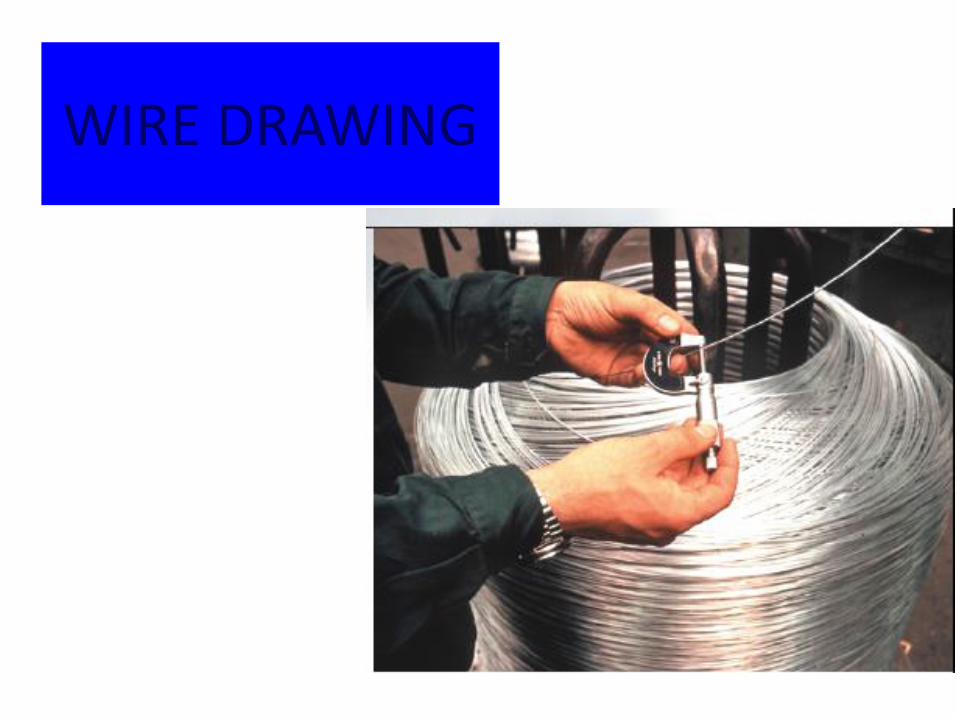
WIRE DRAWING
Transcript of WIRE DRAWING - Mechatronics Engineering Department -...
WIRE DRAWING
Objectives
• • This chapter provides fundamental background on
processes of drawing of rods, wires and tubes.
• • Mathematical approaches for the calculation of drawing
load will be introduced.
• • Finally drawing defects occurring during the process
will be highlighted and its solutions will be included.
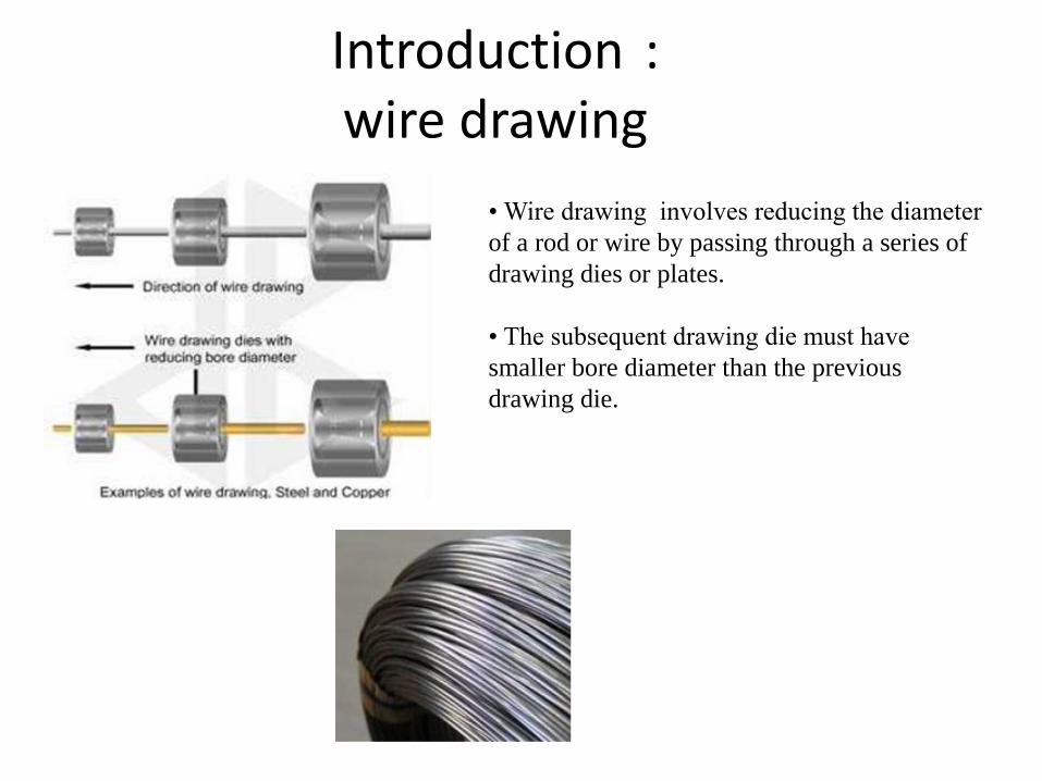
Introduction : wire drawing
• Wire drawing involves reducing the diameter
of a rod or wire by passing through a series of
drawing dies or plates.
• The subsequent drawing die must have
smaller bore diameter than the previous
drawing die.
Introduction
• Drawing operations involve pulling metal through a die by means of a tensile force applied to the exit side of the die.
• The plastic flow is caused by compression force, arising from the reaction of the metal with the die.
• Starting materials: hot rolled stock (ferrous) and extruded (non- ferrous).
• Material should have high ductility and good tensile strength.
• Bar, wire and tube drawing are usually carried out at room temperature, except for large deformation, which leads to considerable rise in temperature during drawing.
• The metal usually has a circular symmetry (but not always, depending on requirements).
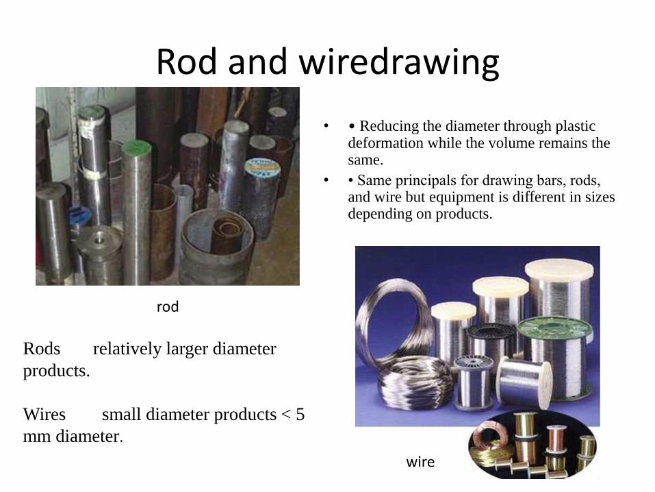
Rod and wiredrawing
• • Reducing the diameter through plastic deformation while the volume remains the same.
• • Same principals for drawing bars, rods, and wire but equipment is different in sizes depending on products.
rod
wire
Rods relatively larger diameter
products.
Wires small diameter products < 5
mm diameter.
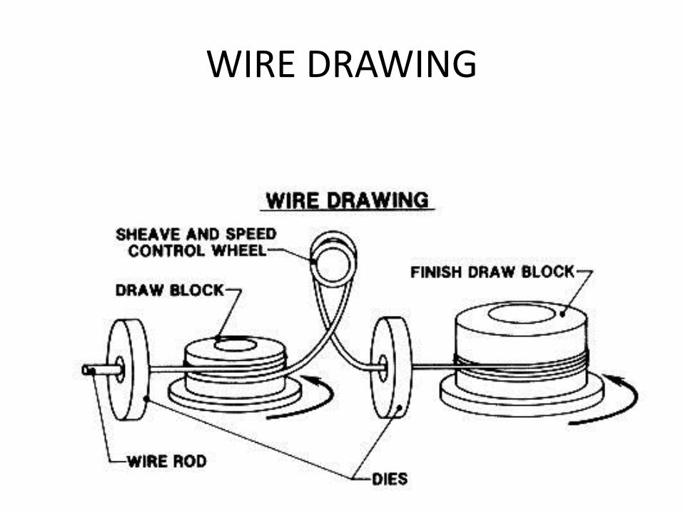
WIRE DRAWING

WIRE DRAWING

Die for Round Drawing
Terminology of a typical die used for drawing round rod or wire.
Tungsten- carbide die insert in a steel casing. Diamond dies, used in drawing thin wire, are encased in a similar manner.

Wire drawing die
Conical drawing die
• Shape of the bell causes hydrostatic pressure
to increase and promotes the flow of lubricant
into the die.
• The approach angle – where the actual
reduction in diameter occurs, giving the half
die angle α
The bearing region produces a frictional drag
on the wire and also remove surface damage
due to die wear, without changing dimensions.
• The back relief allows the metal to expand slightly as the wire leaves the
die and also minimizes abrasion if the drawing stops or the die is
out of alignment.
The die nib made from cemented carbide or
diamond is encased for protection in a thick
steel casing.

Die Materials Overview
• Cemented carbides are the most widely used
for drawing dies due to their superior strength,
toughness, and wear resistance.
• Polycrystalline Diamond (PCD) used for wire
drawing dies – for fine wires. Longer die life,
high resistance to wear, cracking or bearing.
• Most drawing dies are cemented carbide or
industrial diamond (for fine wires).
• Cemented carbide is composed of carbides
of Ti, W, Ni, Mo, Ta,
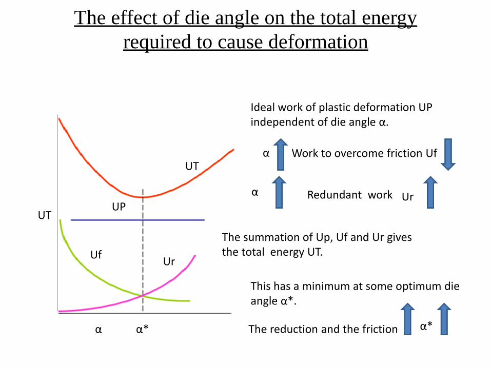
The effect of die angle on the total energy
required to cause deformation
Ideal work of plastic deformation UP independent of die angle α.
α
UT
Work to overcome friction Uf
Redundant work
The summation of Up, Uf and Ur gives the total energy UT.
This has a minimum at some optimum die angle α*.
α
α*
UT
UP
Uf
Ur
Ur
The reduction and the friction α*

Wire drawing process
Hot rolled rod
Pickling, descaling
Lubricating
drawing\
Remove scale -causing surface defects.
• Cu and Sn are used as lubricants for high strength
materials. Or conversion coating such as sulphates
or oxalates.
• Oils and greases for wire drawing
• Mulsifiable oils for wet wire drawing
• Soap for dry drawing.

Mechanical descaling
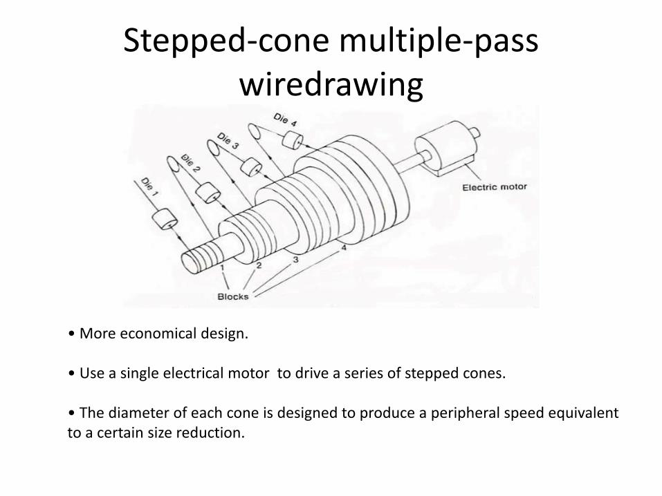
Stepped-cone multiple-pass wiredrawing
• More economical design. • Use a single electrical motor to drive a series of stepped cones. • The diameter of each cone is designed to produce a peripheral speed equivalent to a certain size reduction.
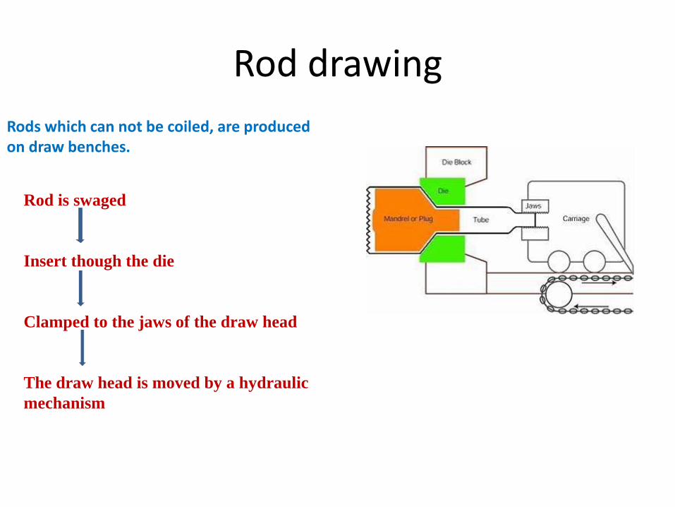
Rod drawing
Rods which can not be coiled, are produced on draw benches.
Rod is swaged
Insert though the die
Clamped to the jaws of the draw head
The draw head is moved by a hydraulic
mechanism

Classification of tube
drawing processes
There are three basic types of tube-drawing processes
• Sinking • Plug drawing - Fixed plug - Floating plug • Mandrel drawing.
Tube sinking Fixed plug Floating plug Moving mandrel

Sinking
• The tube, while passing through the die, shrinks in outer radius from the
original radius
• No internal tooling (internal wall is not supported), the wall then thicken
slightly.
• The final thickness of the tube depends on original diameter of the tube,
the die diameter and friction between tube and die.
• Lower limiting deformation.

Stationary plug
• Use conical plug to control size/shape of inside diameter.
• Use higher drawing loads than floating plug drawing.
• Greater dimensional accuracy than tube sinking.
• Increased friction from the plug limit the reduction in area
(seldom > 30%).
• can draw and coil long lengths of tubing.
Fixed Plug
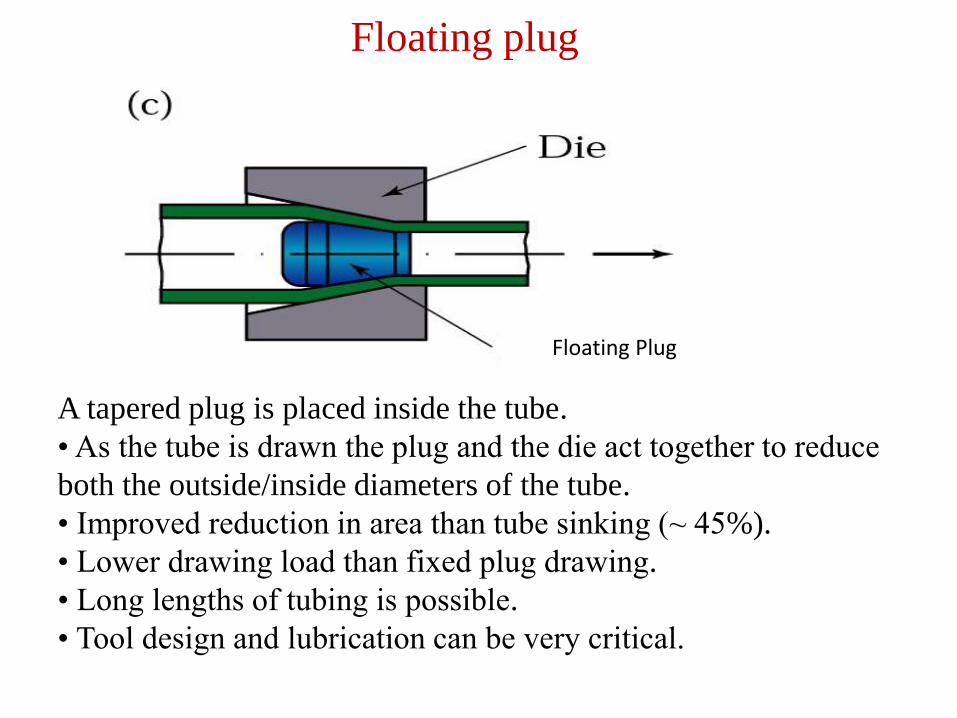
Floating plug
A tapered plug is placed inside the tube.
• As the tube is drawn the plug and the die act together to reduce
both the outside/inside diameters of the tube.
• Improved reduction in area than tube sinking (~ 45%).
• Lower drawing load than fixed plug drawing.
• Long lengths of tubing is possible.
• Tool design and lubrication can be very critical.
Floating Plug
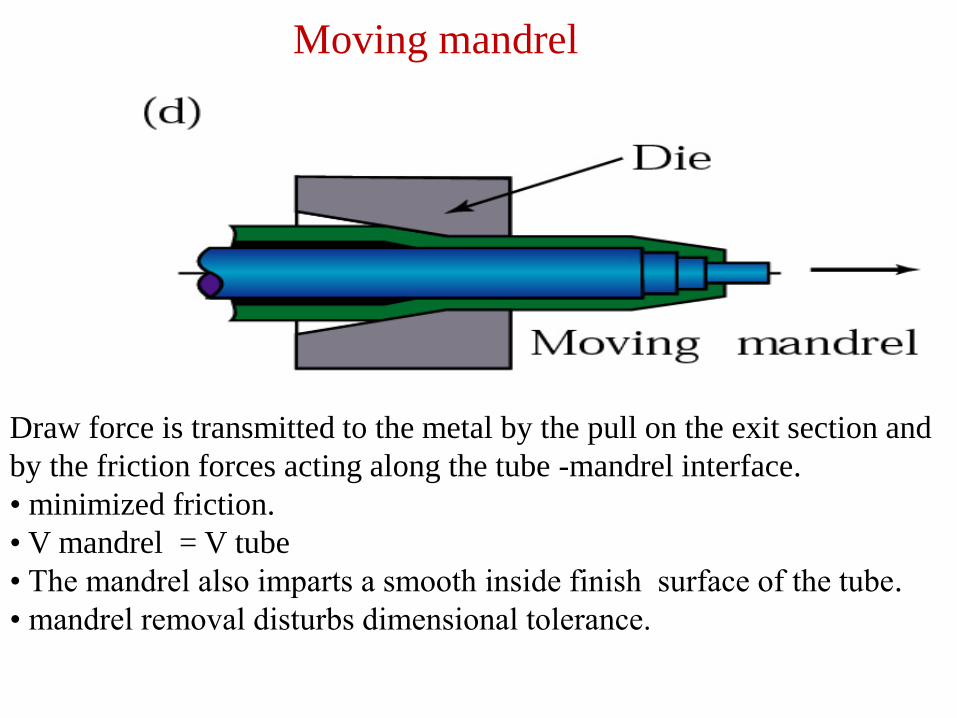
Moving mandrel
Draw force is transmitted to the metal by the pull on the exit section and
by the friction forces acting along the tube -mandrel interface.
• minimized friction.
• V mandrel = V tube
• The mandrel also imparts a smooth inside finish surface of the tube.
• mandrel removal disturbs dimensional tolerance.
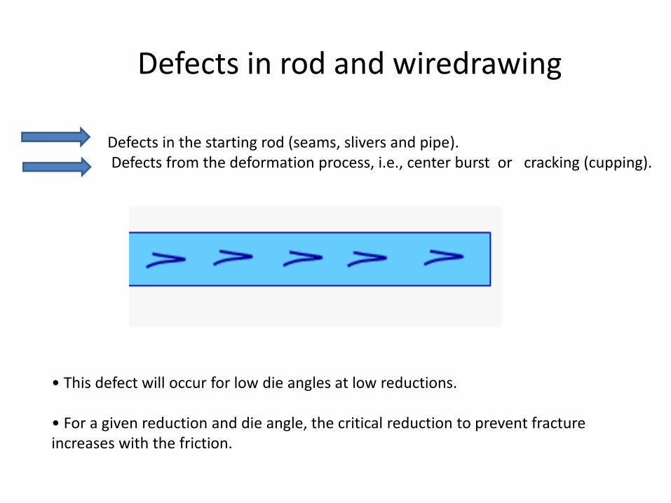
Defects in rod and wiredrawing
Defects in the starting rod (seams, slivers and pipe). Defects from the deformation process, i.e., center burst or cracking (cupping).
• This defect will occur for low die angles at low reductions. • For a given reduction and die angle, the critical reduction to prevent fracture increases with the friction.