Unichiller Installation And User’s Guide
25
Bulletin 30‐32 (Jan 2011) © Unichiller Installation And User’s Guide
Transcript of Unichiller Installation And User’s Guide

Bulletin 30‐32 (Jan 2011)
© Unichiller Installation
And
User’s Guide

Customer Service
If you have questions about Installation, operation and Maintenance of the Unichiller or would like to order replacement parts please use the following contact information.
Customer Service and Technical Support (7 A.M. to 5 P.M. – Central Time)
Phone: 800‐527‐0896 ● 314‐481‐9000
Fax: 314‐457‐9000
Web Site
Visit www.unicosystem.com to find information about Unico Products
©2009 Unico Inc. All rights reserved
This document is subject to change without notice
7401 Alabama Ave., Saint Louis, MO 63111 ● 314‐481‐9000

Contents
General Instructions 1
Placement of the Unichiller 2
Location 2
Clearances 2
Roof Run‐off 2
Equipment Pad 2
Lawn Irrigation 2
Installations Near Salt Water 3
Electrical 3
Piping 3
Chiller Pump Characteristics 3
Effect Of Water Temperature On Pressure Drop 5
Use of Propylene or Ethylene Glycol 5
Installation 6
Connecting Chiller to Water Circuit 6
Chiller Pump Characteristics 6
Electrical 6
Water Side Only Start‐up 6
Digital Temperature Controller (DTC) 7
Programming the DTC 7
DTC Trouble Shooting and Error Messages 8
Full System Start‐up 9
Chiller Maintenance 10
Trouble shooting Guide 11
Chiller Wiring Diagrams 12

1
General Instructions The Unichiller is manufactured to meet US and European electrical requirements. Installation and service must be performed by qualified installer or service agency, and must conform to all national, state, and local codes of the country where it is to be operated. Unichillers have self contained factory charged and tested refrigeration systems containing either R‐22 or R407C refrigerants. The type of refrigerant and quantity is listed on the factory information label located on the back panel. It is not necessary to access the refrigeration system for system installation and start‐up. All Unichillers are tested through a full cooling and heating cycle prior to shipment from the factory.
Before operating, be sure the unit is properly grounded to prevent injury or death from electrical shock!
Disconnect electrical supply before wiring unit to prevent injury or death from electrical shock!
Do not handle the top half of the scroll compressor as it operates at a temperature high enough to cause serious injury.Operation of the chiller without proper freeze protection shall void the warranty. Do not operate this system for long periods of time with water alone. A minimum of 10% propylene or ethylene glycol is essential to prevent freezing. Higher concentrations of glycol are required to prevent heat exchanger from rupturing in cold climates.
Recommended operating temperatures are 115°F for hot water and 40°F for chilled water. Contact Customer Service if you wish to operate at water temperatures outside of the recommended range.
Do not use any liquid solution other than the solution of water and propylene or ethylene glycol in the piping system. The solution must be mixed in accordance with the guidelines in the Unichiller Design Manual.
Pump must be primed (free of air and suction pipe full of liquid) before starting. If pump is run dry, rotating parts will seize and mechanical seal will be damaged.
All electrical wiring should be in accordance with all local codes and regulations. A field provided electrical disconnect shall be installed. The units are safety certified to safety codes of the country they are sold in (refer to Unichiller Specifications Bulletin for further details).
All piping must be in accordance with all local codes and ordinances.
Installation should be in accordance with all local codes and regulations.
These units are designed to operate with R‐22 or R‐407C in a self‐contained, pre‐charged refrigerant system. Do not access the closed refrigerant system for any reason other than after‐sale, after installation component replacement. Such service is to be conducted by qualified personnel only.

2
Placement of the Unichiller
Location
Always locate the chiller outdoors. Never install inside a room. Installing the unit in a pit will reduce performance Locate chiller so that ground water will not enter cabinet. In areas with heavy snow fall it is recommended that the unit be elevated. Do not attach duct work to the chiller. If air deflectors are necessary contact Unico Customer Service
for instructions.
Clearances
The chiller must be placed to provide clearances on all sides for maintenance and inspection.
1. At least 24” must be available on the side of the chiller that accesses the control box, pump and compressor. See Figure 1.
2. Allow at least 60” on the fan side. 3. The remaining two sides should have a minimum clearance of 12”
Roof Run‐off
The Unichiller should not be located where large amounts of water may run‐off from a roof onto or into the unit. Best practices dictate that the chiller be protected from large amounts of run‐off.
Equipment Pad
Place the chiller on a flat solid surface such as a concrete or fabricated slab. The slab should be slightly tilted so that condensation from the chiller will run off the slab and not pool around the chiller.
Lawn Irrigation
Make sure that there are absolutely no sprinkler heads near enough to the chiller that will spray water directly on or into the unit. Keep in mind that prevailing winds may carry mist from sprinklers into the chiller causing damage to electrical connections and mechanical parts.
Figure 1: Unichiller Clearances
12 inches(0.3 m)
6 inches (0.15 m) minimum or24 inches (0.6 m) for service
60 inches(1.5 m)
service accessside
air discharge
air inlet
air inlet
12 inches(0.3 m)
12 inches max(0.3 m)
shrubs or porous wall
Maximum height of wallis 4.5 ft (1.4 m)
Overhang
TOP VIEW
FRONT VIEW
24 inches(0.6 m)

3
Installations Near Salt Water
When installing the chiller in coastal areas near salt water it is best to install the chiller so that the building is between the shore and the unit. To improve the lifetime it is best to request a technicoat condenser coil.
Electrical
All electrical connections supplied to the chiller must meet National and local codes.
Check for proper line voltage for the chiller and blower modules – if used. Low line voltages may require the use of a soft start upgrade. Check with Customer Service to determine whether or not a soft start upgrade will be necessary.
Piping
Make sure all pipe sizing conforms to flow requirements.
Recommended chiller piping connections is 1” minimum. Air in the piping system can damage the pump seals. Make sure that in the case of a non sealed water storage system that air separators or air vents are placed in inlet side of the piping system.
Chiller Pump Characteristics The chiller can be ordered with or without an internal water pump. When installing the chiller to the existing water circuit it may be necessary to trouble shoot the water circuit. Figure 2 outlines important data regarding chiller characteristics with and without the pump to aid in the trouble shooting process.
0 5 10 15 20 250
5
10
15
20
25
30
35
0.0 0.2 0.4 0.6 0.8 1.0 1.2 1.4
0
25
50
75
100
125
150
175
200
225
0
10
20
30
40
50
60
70
80 Pump Curve External Static Pressure (UniChiller with pump) Internal Pressure Drop (UniChiller without pump)
0601. UCH(R)0604‐1,22. UCH(R)0604‐33. UCH(R)0604‐6,7,84. UCH(R)0364‐1,25. UCH(R)0364‐36. UCH(R)0364‐6,7,8
R0843: Catalog46/3/2009
Pre
ssur
e D
iffer
ence
Water Flow Rate
GPM
UniChiller models UCHR PSI
16 2345
036
1/60/230V1/60/264V
1/50/260V
L/s
GPM
kPa
ft.water
Figure 2. Water flow and pressure differentials for various chiller models.

4
Additional information regarding pump characteristics are given in Table 1.
Table 1. Pump characteristics based on flow rates and voltage for each of the chiller models. Bolded lettering indicates optimum system values.
(English Units)
(SI Units)
Options: ‐**0GPM ISP (psi) ESP (psi) SP(psi) Watts Amps ESP (psi) SP(psi) Watts Amps ESP (psi) SP(psi) Watts Amps4 2.5 26.2 27.6 465 2.00 24.9 27.7 515 2.12 24.7 27.4 540 2.266 4.6 23.6 27.0 495 2.12 22.2 27.1 540 2.20 21.7 26.5 565 2.367.2 6.0 21.8 26.6 510 2.18 20.4 26.7 555 2.24 19.8 26.0 580 2.408 7.0 20.6 26.4 520 2.22 19.2 26.4 565 2.28 18.4 25.6 585 2.4410 9.9 17.4 25.8 550 2.34 15.9 25.8 590 2.36 14.8 24.7 610 2.5412 13.0 13.8 25.3 575 2.46 12.3 25.2 610 2.44 10.9 23.8 630 2.6214 16.4 9.9 24.7 600 2.58 8.4 24.6 635 2.54 6.7 22.9 650 2.7216 20.0 5.8 24.1 630 2.70 4.2 24.0 660 2.62 2.2 22.0 675 2.80
‐1*2, ‐2*2 @ 230V ‐3*2 @ 265V ‐6*2, ‐7*2, ‐8*2 @ 240VUCHR0364
Options: ‐**0GPM ISP (psi) ESP (psi) SP(psi) Watts Amps ESP (psi) SP(psi) Watts Amps ESP (psi) SP(psi) Watts Amps4 0.6 27.9 27.6 465 2.00 26.5 27.7 515 2.12 26.3 27.4 540 2.266 1.4 26.3 27.0 495 2.12 24.9 27.1 540 2.20 24.4 26.5 565 2.368 2.4 24.5 26.4 520 2.22 23.0 26.4 565 2.28 22.3 25.6 585 2.4410 3.6 22.5 25.8 550 2.34 21.0 25.8 590 2.36 19.9 24.7 610 2.5412 5.1 20.2 25.3 575 2.46 18.7 25.2 610 2.44 17.3 23.8 630 2.6214 6.9 17.8 24.7 600 2.58 16.2 24.6 635 2.54 14.6 22.9 650 2.7216 8.8 15.1 24.1 630 2.70 13.5 24.0 660 2.62 11.5 22.0 675 2.8020 13.5 9.1 23.0 685 2.92 7.4 22.7 705 2.78 4.9 20.2 720 2.98
UCHR0604‐1*2, ‐2*2 @ 230V ‐3*2 @ 265V ‐6*2, ‐7*2, ‐8*2 @ 240V
Options: ‐**0L/s ISP (kPa) ESP (kPa) SP(kPa) Watts Amps ESP (kPa) SP(kPa) Watts Amps ESP (kPa) SP(kPa) Watts Amps0.30 22 174 189 475 2.04 165 189 525 2.14 163 187 550 2.300.40 34 159 185 500 2.14 150 186 545 2.22 146 182 570 2.360.45 41 151 184 510 2.18 142 184 555 2.24 137 179 575 2.400.50 48 143 182 520 2.22 133 182 565 2.28 128 177 585 2.440.60 63 125 179 540 2.32 115 179 580 2.34 108 172 605 2.520.70 79 107 176 565 2.40 96 176 600 2.42 88 167 620 2.580.80 97 86 173 585 2.50 76 172 620 2.48 66 162 640 2.660.90 116 65 170 605 2.58 54 169 640 2.54 42 157 655 2.721.00 136 42 167 625 2.68 31 166 660 2.62 18 152 675 2.80
UCHR0364‐1*2, ‐2*2 @ 230V ‐3*2 @ 265V ‐6*2, ‐7*2, ‐8*2 @ 240V
Options: ‐**0L/s ISP (kPa) ESP (kPa) SP(kPa) Watts Amps ESP (kPa) SP(kPa) Watts Amps ESP (kPa) SP(kPa) Watts Amps0.40 11 179 185 500 2.14 170 186 545 2.22 166 182 570 2.360.50 16 169 182 520 2.22 159 182 565 2.28 154 177 585 2.440.60 23 158 179 540 2.32 148 179 580 2.34 141 172 605 2.520.70 31 147 176 565 2.40 136 176 600 2.42 128 167 620 2.580.75 35 140 174 575 2.46 130 174 610 2.44 121 165 630 2.620.80 39 134 173 585 2.50 123 172 620 2.48 113 162 640 2.660.90 49 120 170 605 2.58 109 169 640 2.54 98 157 655 2.721.00 60 105 167 625 2.68 94 166 660 2.62 81 152 675 2.801.10 72 90 163 650 2.78 79 162 675 2.68 64 147 690 2.86
UCHR0604‐1*2, ‐2*2 @ 230V ‐3*2 @ 265V ‐6*2, ‐7*2, ‐8*2 @ 240V

5
Effect of Water Temperature on Pressure Drop The temperature of the water can affect the pressure drop on the chiller system Table 2 lists the coefficients used to calculate pressure drop due to temperature.
Table 2. Pressure Drop Correction Factor Based on Temperature (for water)
Temperature °F 32 40 50 60 68 90 100 110 120 130
°C (0) (4.4) (10) (15.6) (20) (32.2) (37.8) (43.3) (48.9) (54.4)
Factor 1.16 1.12 1.05 1.03 1.00 0.93 0.91 0.89 0.86 0.84
Use of Propylene or Ethylene Glycol The Chiller can reach water temperatures well below freezing. Therefore it is recommended that the water system be charged with a minimum 10% glycol solution. Higher percentages of glycol will be necessary when the chiller is operated in regions of the country where outdoor temperatures fall below freezing. Table 3 gives the recommended glycol percentages depending on the expected low temperatures for the region.
Table 3. Percentage of propylene glycol solution necessary to protect chiller system in cold weather.
% Propylene Glycol 10% 20% 30% 40% 50% Minimum Ambient
Temperature
F 26 18 8 ‐7 ‐29
C ‐3.3 ‐7.8 ‐12.8 ‐21.7 ‐33.9
The percentage of propylene glycol can affect the pressure drop on the system. Table 4 lists the correction factors recommend to calculate pressure drop based on the percentage of glycol in the system.
Table 4. Pressure Drop Correction Factor Based on Percentage of Glycol
% Glycol 0 10 20 30 40 50 Propylene Glycol 1.00 1.10 1.20 1.34 1.50 1.65
Ethylene Glycol 1.00 1.00 1.06 1.16 1.25 1.36
6
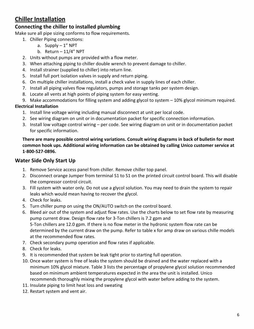
Chiller Installation Connecting the chiller to installed plumbing Make sure all pipe sizing conforms to flow requirements.
1. Chiller Piping connections: a. Supply – 1” NPT b. Return – 11/4” NPT
2. Units without pumps are provided with a flow meter. 3. When attaching piping to chiller double wrench to prevent damage to chiller. 4. Install strainer (supplied to chiller) into return line. 5. Install full port isolation valves in supply and return piping. 6. On multiple chiller installations, install a check valve in supply lines of each chiller. 7. Install all piping valves flow regulators, pumps and storage tanks per system design. 8. Locate all vents at high points of piping system for easy venting. 9. Make accommodations for filling system and adding glycol to system – 10% glycol minimum required.
Electrical Installation 1. Install line voltage wiring including manual disconnect at unit per local code. 2. See wiring diagram on unit or in documentation packet for specific connection information. 3. Install low voltage control wiring – per code. See wiring diagram on unit or in documentation packet
for specific information.
There are many possible control wiring variations. Consult wiring diagrams in back of bulletin for most common hook ups. Additional wiring information can be obtained by calling Unico customer service at 1‐800‐527‐0896.
Water Side Only Start Up
1. Remove Service access panel from chiller. Remove chiller top panel. 2. Disconnect orange Jumper from terminal S1 to S1 on the printed circuit control board. This will disable
the compressor control circuit. 3. Fill system with water only. Do not use a glycol solution. You may need to drain the system to repair
leaks which would mean having to recover the glycol. 4. Check for leaks. 5. Turn chiller pump on using the ON/AUTO switch on the control board. 6. Bleed air out of the system and adjust flow rates. Use the charts below to set flow rate by measuring
pump current draw. Design flow rate for 3‐Ton chillers is 7.2 gpm and 5‐Ton chillers are 12.0 gpm. If there is no flow meter in the hydronic system flow rate can be determined by the current draw on the pump. Refer to table x for amp draw on various chille models at the recommended flow rates.
7. Check secondary pump operation and flow rates if applicable. 8. Check for leaks. 9. It is recommended that system be leak tight prior to starting full operation. 10. Once water system is free of leaks the system should be drained and the water replaced with a
minimum 10% glycol mixture. Table 3 lists the percentage of propylene glycol solution recommended based on minimum ambient temperatures expected in the area the unit is installed. Unico recommends thoroughly mixing the propylene glycol with water before adding to the system.
11. Insulate piping to limit heat loss and sweating 12. Restart system and vent air.

7
Digital Temperature Controller (DTC) Programming the DTC
1. Press “Set” key to enter program mode. 2. Annunciator will display either an “F” for Fahrenheit or a “C” for Celsius. Use the up or down arrow
keys to toggle between the two selections. Press “Set “ when the desired temperature scale has been selected. Press “Set” key to input the scale and move to the next setting.
3. Annunciator will now display “S1” heating set point. Use the up or down arrow keys to change the set point. Reccomended heating set point for start up purposes is 115° F. Press “set “ key to input desired temperature value and move to next setting.
4. Annunciator will now display a blinking “DIF 1” the heating differential temperature setting. Recommended setting is 10. Use the up and down arrow keys to set to 10. Press “set “ key to input desired temperature value and move to next setting.
5. Annunciator will now display “C1/H1 Cooling or Heating mode. Use up or down arrow keyto toggle between C1 and H1. Choose H1. Press “Set” key.
6. Annunciator will now display a blinking “S2” Cooling set point. Use up and down arrow keys to select the desired temperature. Recommended cooling temperature at start up is 44° F. Press “set “ key to input desired temperature value and move to next setting.
7. Annunciator will now display a blinking “DIF 2” Cooling Differential Temperature. Recommended setting is 10. Use the up and down arrow keys to set to 10. Press “set “ key to input desired temperature value and move to next setting.
8. Annunciator will now display “C2/H2” Cooling or Heating mode. Use up or down arrow key to select C2. Press “set “ key to input desired temperature value. and move to next setting.
9. DTC will now be in operating mode and will display current water temperature.

8
DTC Trouble Shooting and Error Messages
When not working properly, the DTC will display error codes on the annunciator. A description of the error codes , what condition may cause the code to come up and how to clear the error are listed in table 5.
Table 5. DTC Troubleshooting Error Messages
Display Message
Description To Correct
E1 Appears when either the up or down key is pressed when not in the programming mode.
If the E1 message appears even when no keys are being pressed, replace the control.
E2 Appears if the control settings are not properly stored in memory.
Check all settings and correct if necessary.
EP Appears when the probe is open, shorted or sensing a temperature that is out of range.
Check to see if the sensed temperature is out of range. If not, check for probe damage by comparing it to a known ambient temperature between 30°F and 220°F. Replace the probe if necessary.
EE Appears if the EEPROM data has been corrupted.
This condition cannot be field repaired. Replace the control.
CL Appears if calibration mode has been entered.
Remove power to the control for at least five seconds. Reapply power. If the CL message still repairs, replace the control.

9
Full System Start Up 1. Shut down main power to chiller, 2. Reconnect orange wire to terminals S1 and S1 on control board. 3. Turn on main power to chillers, Air Handlers, Pumps and Controls. 4. Use “Run/Auto” switch on chiller control board to operate chiller. 5. Using Table 6 determine the correct switch positions for the desired chiller operation.
Table 6. Chiller operation as determined by control board switch positions.
Run/ Auto Switch Position
Heat /Cool Switch Position
Resulting Chiller Operation
Run Heat Heating mode only. Water temperature controlled by DTC. Run Cool Cooling Mode only. Water temperature controlled by DTC. Auto Heat Externally controlled heating only. Auto Cool Externally controlled heating and cooling.
6. Check flow rates through system and adjust as necessary. 7. During normal operation there should be a 8‐10F temperature difference between water going into
the chiller and water coming out. Temperature differences greater or less than 8‐10 may indicate a water flow problem.
8. After 24 hours run time remove strainer and clean filter screen of dirt and debris. The screen can be removes but should be retained incase it is necessary to do any major repairs or upgrades on the water system.
9. Accessing refrigerant system is not necessary under normal circumstances. 10. Fill out bulletin 30‐101 unichiller service report. Leave a copy with the customer and retain one for
your files. 11. If chiller does not operate properly, refer to the trouble shooting guide in this manual or contact Unico
Customer service at 800‐527‐0896.

10
Unichiller Maintenance The following are the periodic maintenance requirements of Unichillers 1. Clean the coil surfaces at least twice a year or when visibly dirty by hosing the coil with water. Using a
coil cleaner is optional.
Do not use high pressure sprayer to clean the coil as this may damage or flatten the fins.
2. If there is the proper level of freeze protection in the lines, there is no need to drain the system if it will not be run over the winter months. Unico recommends using propylene glycol for freeze protection. Refer to Table 3 for required percentages of propylene glycol. To measure the freeze protection level in the system take a sample of the fluid through the drain or storage tank and use an anti freeze tester or an anti freeze refractometer that is suitable for the glycol (ethylene or propylene) that is used in the system.
3. If the chiller is to be drained over the winter months it is important that all water is removed from the heat exchanger. Drain system from the Inlet connection. Use a wet/dry vacuum to remove residual water. Or blow the excess water out from the output water connection.
4. The Unichillers are pre‐charged with R‐22 or R‐407C refrigerants. Only experienced licensed refrigerant service personnel should check the charge and repair leaks should they occur.

11
Troubleshooting Guide The printed circuit board has test points which can be used for trouble shooting. When trouble shooting insert the common probe of the volt meter into the COM terminal on the circuit board and probe the test points for voltage readings. Table 7 lists common trouble shooting test points and what it means when they read 24V+/‐ 2 volts.
Socket For Common ProbeFrom Volt Meter
Figure 4. Close‐up of lower left Hand corner of printed circuit board showing some test pins common probe socket. Table 7. Low Voltage Test Pins at 24V AC
Test Pin Number
A reading of 24V from the test pin listed to common indicates the following:
19 Chiller has power; Transformer connected and good 6 External call for chiller; enable pump 18 Flow switch or timer is closed 14 External call for compressor 13 High Pressure Switch is closed 12 Low Pressure Switch is closed (or defrost relay is energized if in defrost) 17 Digital Temperature Controller Calling for Heating or Cooling 8 Timer Is Not In Time Delay Mode; Contactor Is Energized 7 Not in Defrost Or Defrost Pressure Switch (DPS) Is Closed Due To High Pressure
9 Pressures Normal, Low Ambient Pressure Switch (if cooling) Mild Weather Pressure Switch (if heating) are closed; Fan relay is energized
10 Fan Relay Is Energized 4 In Defrost Mode; Defrost relay is energized 1 External Call For Heat Mode
Table 8. High Voltage Test Pins
22 and 24 Unit is correctly Powered 22 and 23 Fan Relay Is Closed (Fan Should Be On) 22 and 21 Pump Relay is Closed (Pump Relay Should be On) 22 and 26 Heater Relay Is Closed (Should Be In Defrost Mode)

12
The following table is to be used for troubleshooting problems that may occur with the chiller. This table should be used only if there are no modifications to the controls. Table 9a: Unichiller Troubleshooting Chart ‐ Main
Problem Probable Cause Corrective Action
Upon start up nothing happens
Power not getting to the chiller or the control board.
Check power coming into the unit. Confirm Auto/Run Switch is set to Run. Test for 230V between TP 22 and TP24. 277V for 3p/460V chillers – unit is correctly powered. Check circuit board terminal block for 24 volts between R and C – Board powered up.
Bypass Timer Bad
Pump does not come on. Water flow restricted, defective flow switch, pump relay not closed
See pump troubleshooting.
Pump does not stay on
No water in the system. Put water in the system.
Water temperature set point is too high/low.
Adjust the temperature controller set point (no lower than 38˚F for cooling, no higher than 125˚F for heating).
Faulty temperature controller. Check the operation of the temperature controller. If faulty, replace.
No Low voltage Check for 24V on transformer. Fuse on control board
Unichiller shuts down completely (including the pump).
Open flow switch (Liquid solution is interrupted or air in the system).
Check for air or debris in the system.
Table 9b: Unichiller Troubleshooting Chart ‐ Compressor
Problem Probable Cause Corrective Action
Compressor and fan motors shut down before the set water temperature is reached.
Open low‐pressure switch.
Check for a refrigerant leak, inoperative thermal expansion valve, low liquid solution control setting, low ambient operation, or low liquid solution flow.
Open Compressor time delayBad Defrost BoardBad DTC
Open high‐pressure switch. Check for a dirty condenser, inoperable fan motor(s), or the re‐circulation of condenser air.

13
Table 9c: Unichiller Troubleshooting Chart ‐ Pump
Problem Probable Cause Corrective Action
Pump shuts off shortly after the power is applied from the circuit breaker with switch turned to cool or heat position.
Air in the system or lack of water in the system.
Purge the air in the system by opening the vent plug on the pump. Install auto air vent. Check wye strainer.
Low water flow.
Check pipe sizing and operation of the pump. Flow switch will open at flow rates less than 3gpm.
Faulty flow switch. Check continuity of the flow switch. If faulty, replace.
Table 9d: Unichiller Troubleshooting Chart ‐ Other
Problem Probable Cause Corrective Action Air in the system or lack of water in the system.
Water leak. Check for cracked pipe or loose fittings. Repair, if necessary.

14
This Page Is Intentionally Left Blank

14

15

16

17

18

19

20

21