UNCLASSIFIED AD NUMBER - Defense Technical ... AD NUMBER AD868557 NEW LIMITATION CHANGE TO Approved...
32
UNCLASSIFIED AD NUMBER AD868557 NEW LIMITATION CHANGE TO Approved for public release, distribution unlimited FROM Distribution authorized to U.S. Gov't. agencies and their contractors; Administrative/Operational Use; 26 NOV 1969. Other requests shall be referred to Army Test and Evaluation Command, Aberdeen Proving Ground, MD,. AUTHORITY USATEC ltr, 14 Dec 1970 THIS PAGE IS UNCLASSIFIED
-
Upload
trinhnguyet -
Category
Documents
-
view
220 -
download
1
Transcript of UNCLASSIFIED AD NUMBER - Defense Technical ... AD NUMBER AD868557 NEW LIMITATION CHANGE TO Approved...

UNCLASSIFIED
AD NUMBER
AD868557
NEW LIMITATION CHANGE
TOApproved for public release, distributionunlimited
FROMDistribution authorized to U.S. Gov't.agencies and their contractors;Administrative/Operational Use; 26 NOV1969. Other requests shall be referred toArmy Test and Evaluation Command, AberdeenProving Ground, MD,.
AUTHORITY
USATEC ltr, 14 Dec 1970
THIS PAGE IS UNCLASSIFIED

Materiel Test Procedure 7-2-105S 26 November 1969 General Equipment Test Activity
U. S. ARMY TEST AND EVALUATION COMMAND
COMMODITY ENGINEERING TEST PROCEDURE
TRACTOR, WHEELED, AIRCRAFT, TOWING
*. OBJECTIVE*
This document provides test methodology and techniques necessary to•. kA determine the technical performance and safety characteristics of wheeled air-E, w• craft towing tractors and associated tools and ecuipment as described in Quali-
W tative Materiel Requirements (QMR's), Small Development Requirements (SDR's),Technical Characteristics (TC's), as indicated by the particular design and todetermine the technical suitability of the item for service test.
2. BACKGROUND
Requirements exist for wheeled, tractor vehicles powered by diesel orgasoline internal combustion engines suitable for towing aircraft and other aero-nautical equipment in all types of weather on concrete, sand, clay, or roughterrain surfaces.
These wheeled tractors are required in a variety of capacities, typicallyranging from drawbar pull values of 4,000 to 75,000 pounds. In general, thetractors are to have a short, compact wheel base suitable for maneuvering in re-stricted areas in addition to a low-profile style design to facilitate operation
G1 in and around "paeked aircraft.
Certain tractors will be required to contain systems for starting jetor reciprocating engines and/or facilities for providing total aircraft electricalpower requirements. Also, tractors will normally be required to carry fire ex-tinguishers, provide winch services, and contain storage space for tools and chock-blocks.
All wheeled aircraft towing tractors are required to be of rugged con-struction and of a design essentially free of interference or obstructions to air-craft servicing.
3.REQUIRED EQUIET
a. POL Materials.b. Stop Watch. Rop.'JceI by the , rT ' : j
c. Inclinometer. CLEARINGHOUSEd. Pressure Gauges. for Federal Scientific & Technical ." • L. _
Information Springfield Va. 22151e. M4easuring Tapes. • -
f. Pressure-Type Indicating Device/Gauge suitable for attachnent•test item clutch pedal.
*This MTP is intended to be used as a basic guide in preparing actual*test plans for the subject equipment. Specific criteria and test procedures must'e determined only after careful appraisal of pertinent QMR's, SDR's, TC's,"ýd any other applicable doc
This domment is subject to speolsl Mport controls ad 9e6hransmittal to forsei•n goverrat o to Ie•wi•a bei
Aooi wth rapoa-rMM

MTP 7-2-10526 November 1969
g. Meteorological Instruments.h. Adapter Pully with diameter equal to test item hand steering wheel
diameter.i. Tension Dynamometer.J. Platform Scale.k. Steel Cable; Chain; Hooks (for lifting attachment test and drawbar
pull test).1.. Photoelectric Switches and Timing Device (electronic).m. Materials for obstacle block construction.n. Trailing Load(s) for test item (equal in gross weight to ten times
rated drawbar pull value).o. Maintenance and Inspection Facilities.p. Laboratory and/or Bench Testing Facilities, as re--'-id.q. Endurance and Durability Test Course, as described in Appendix A.r. Equipment and Facilities as described in referenced MTP's.
4. REFERENCES
A. USATECOM Regulation 385-6, Verification of Safety of MaterielDuring Testing.
B. USATECOM Regulation 700-1, Value Engitieering.C. USATECOM Regulation 705-4, Equipment Performance Report.D. MIL-STD-129, Marking for Shipment and Storage.E. MIL-STD-130, Identification Marking of U. S. Military Property.F. MIL-STD-259C, Test and Inspection of Tractor, Wheeled, Warehouse.G. MIL-STD-461, Electromagnetic Interference Characteristics Require-
ments for Equipment.H. MIL-STD-462, Electromagnetic Interference Characteristics Measure-
ments of.I. MIL-STD-463, Definitions and System of Units, Electromagnetic
Interference Technology.J. MIL-STD-1472, Human Engineering Design Criteria for Military Systems,
Equipment and Facilities.K. MIL-E-11275, Zngines, Gasoline. Industrial Type, General Specifica-
tions for.L. MIL-T-46729, Tire, Pneumatic, for Military Ground Vehicles.M. USAGETA Document, Human Factors Evaluation Data for General Equip-
/ ment (HEDGE).N, Underwriter's Laboratories, Inc. UL558: Standards for Safety of
Internal Combustion Engine - Powered Industrial Trucks.0. AR 70-38, Research. Development, Test, and Evaluation of Materiel
for Extreme- Climatic Conditions.P. HEL-STD-S-1-63B, Maximum Noise Level for AMC Equipment.Q. TB MED 251, Noise znd Conservation of Hearing.R. MTP 2-2-500, Vehicle Characteristics.S. M1T 2-2-502, Inspection (Automotive).T. MTP 2-2-503, Maintenance.U. MTP 2-2-505, Preliminary Operation.V. MTP 2-2-508, Safety Evaluation (Automotive).W. M1T 2-2-520, Logistics-Over-The-Shore (LOTS).X. 1TP 2-2-601, Electrical Systems (Automotive).
-2-
.3 _ - - .- -_ _ __-- , .. m m m un m n • m m mm m m

MIT 7-2-10526 Novemberl969
Y. HTP 2-2-602, Acceleration: MhaxiLm & Minimm •I•eds.
* Z. mTP 2-2-603, Vehicle Fuel Conswption.AA. MrP 2-2-604, Drawbar Pull.AB. MP 2-2-605, 'Towing Ressistance.AC. MVI? 2-2-607, Engine and Power Train Systems CooLie+ (Vehiae.:+ ~~AD. F. a -2-68 arkn.ketd. Vehicle.",+'AE. MTP 2-2-609, Steering. •+AF. NT 2-2-610, GadeabilitZ & Side Slope Performance Mobility. - -AG. MTP 2-2-612, For U
AH. MTP 2-2-614, Carbon Monoxide zards Test for Vehicles.Al. MP 2-2-619, Off-Road Vehicle Mobility Test.AJ. MIP 2-2-650, Cold Starting and Wan&-up.
AK. [ 2-2-7o0, Laboratory Tests of Reciprocatilng Internal CombustionEnsines.
AL. KW 2-2-703, Laboratory Tests of Power Train Components.AM. MTP 2-2-,704, TIre...s. •+AN. MTP 2-2-707, Kits (Vehicle).AO. MiT 2-2-708, Personnel Heating Systems.AP. MIP 2-2-712, Automotive Winches.AQ. MTP 2-2-800, Center of Gravity.AR. HIP 2-2-802, Stowage.AS. NT? 2-2-803, Human factors Enineering (Vehicles).AT. MIP 7-2-515, Air Transport (Suitability of EquiLpent for).AU. MIP 9-2-136, Generating and Charging Plants.AV. MIP 9-2-166, Air Comwressor.AW. HIP 10-2-501, Operator Training and Familiarization.AX. MIP 10-2-503, Surface Transportability (General Supplies and Iquip
Met).AY. MIP 10-2-508, SafetY.
5. SCOPE
5.1 SiNAY
he This procedure describes the preparation for and methods of evaluatingthe technical characteristics of wheeled aircraft towing tractors and their suit-ability for service testing. The required tests are summarized as follows:
a. Preparation for Test - A determination of the condition and physicalcharacteristics of the test item upon arrival, to ensure that the test item iscomplete and functionally operational, determination of the performance and en-durance of the test item major components and to provide operator training and
familiarization procedures.b. Subsystem tests - These procedures provide fo-% the testing of test
item components/assemblies/subassemblies which do not requir• tractor disassemblyor component bench testing. The following individual tests are included:
1) Clutch Pedal Test.2) Steering Wheel Test.3) Brake Tests.4) Electrical System Test.
-3- 4-
I.

MTi 7-2-10526 November 1969
5) Cooling System Test6) Exhaust System Tests7) Accessory Tests8) Power-Train Tests
c. Overall Tractor Performance Tests - These procedures provide forthe testing of the test item as a unit or system. The following tests are per-formed:
•'1
1) Drawbar Pull Test2) Acceleration-Acceleration Response Test3) Speed Test4) Fuel Consumption Test5) Turning Radius Test6) Gradeability and Side Slope Performance Test7) Fording Test8) Mobility Test9) Endurance and Durability Test
10) Broadband Radio Interference Test11) Magnetic Permeability Property Test
d. Transportability - An evaluation to determine the ability of thetest item to withstand the forces which it will experience during normal hand-ling and transportation. 1.)
e. Maintenance - An evaluation to determine and appraise the testitem's maintenance characteristics and requirements, a verification and apprais-al of its malfunctions, an evaluation of the test item's associated publications"and other coemon and special support elements (maintenance test package), an ap-praisal of the test item's design for maintainability (AMCP 706-134: accessibil-ity, ease of maintenance, standardization, and interchangeability), an evaluationof component and system durability and reliability, and the calculation of indi-
"iI cators which express the effects of appropriate preceding aspects.f. Safety - An evaluation to determine the safety characteristics and
possible hazards of the test item and to provide information for a safety re-lease.
g. Human Factors Evaluation - An evaluation to determine the adequacyof the design and performance characteristics of the test item and associatedequipment in terms of conformance to accepted human factors engineering designcriteria.
h. Value Analysis - An evaluation directed at analyzing the primaryfunction and features of the test item for the purpose of reducing the cost ofthe test item without compromising performance and safety characteristics.
5.2 LIMITATIONS
None
6, PROCEDURES
-4-

S'4
MIP 7-2-105 -26 No ember 1969r, U
6.1 PREPARATION FOR TEST6.1.1 Initial Inspection
Upon receipt of the test item at the test site, perform applicableprocedures of MTP 2-2-502 and the following:
a. Visually inspect the assembled test item, including the blocking,) crating, or other materials used for rail shipment. Record the following:
I) Evidence of damage or deterioration of test item or materialsused for protection during shipment.
2) Identification markings which were not in accordance with
MIL-STD-129, MIL-STD-130, or test item detail specification.
b. Remove test item from the carrier; unpack and remove all tracesof protective transport/storage materials. When this has been accomplished,visually inspect the test item. Record evidence of defects in the followingareas:
1) Manufacturing2) Material3) Workmanship
6.1.2 Inventory Check
a. Conduct an inventory against the Basic Issue Items List (BIIL).Record evidence of the following:
1) jirssing maintenance literature or draft technical manuals.2) Shortages in repair parts, accessories, or tools.3) Missing kits.4) Missing parts, tools, or other components of the maintenance
package.
b. Submit an Equipmnt Performance Report (EPR) for each noted shortageor discrepancy.
6.1.3 Inspection and Preliminary Operation
a. Perform periodic inspection(s) and maintenance as required by thedraft technical manual and in accordance with applicable procedures of MIP 2-2-502.
b. Establish that the actual test item serial number and engine identi-fication number match those numbers which appear on records accompanying the testitem.
c. Read the test item running-time meter; if the total elapsed operat-ing time is less than four hours, or less than an otherwise specified elapsed.time, subject the test item to the break-in procedures of MIP 2-2-505.
-5-
4
Gt -
i'-

MTP 7-2-10526 November 1969
6.1.4 Pre-Test Evaluations
Determine the performance and endurance of wheeled aircraft towingtractor's major components and the suitability of testing the tractor- as asystem by performing the following: *
6.1.4.1 Reciprocating Internal Combustion Engine Tests
j ~Subject the test item engine type to the procedures of MTlP 2-2-700and the selection criteria of MIL-E-11275.
6.1.4.2 Power Train Component Tests
Subject test item power train components (clutch, transmission,transfer case,, drive shaft, differential, axles, and brakes) to the proceduresof MTP 2-2-703.
6.1.4.3 Tire Tests (For new makes of tires only)
* I Subject test item tire type(s) to the procedures of ?rP 2-2-704 andthe selection criteria of MIL-T-46729.
6.1.5 Physical Characteristics
a. Determine the physical characteristics of the test item asdescribed in the applicable portions of the general, design and physical datasections of MTP 2-2-500, with emphasis on the following:
1) Engine make and model2) Test item length, less coupler(s)3) Width4) Height, less cab5) Wheelbase6) Ground clearance7) Governed speed
S8) Gross vehicle weight
b. Determine and record the following:
1) Counterweight information, e.g., removable, weight, etc.2) Drive-steer provisions, e.g., two wheel drive, two wheel
steer, etc.3. Aircraft service facilities provided, e.g., starting compres-
sor, etc.4. Safety equipment supplied.
c. Determine the vertical and horizontal center of gravity asmeasured from the drive axle, by utilization of applicable procedures ofKp 2-2-800.
6.1.6 Operator Trainina and Familiarization
"-6-

KE 7-2-10526 Novembe "1969
Train test personnel in accordance with the applicable procedures of
MTP 10-2-501 and record all pertinent data.
6.2 TEST CONDUCT
NOTE: All equipment failures shall be reported in accordance withUSATECOM Regulation 705-4.
6.2.1 Subsystem Tests
Test the following components/assembliedsubassemblies wit:..tt dis-assembling the test item:
6.2.1.1 Clutch Pedal Test
To determine the force required to depress the test item clutch pedal,
proceed as follows:
a. Obtain a scale indicating device (pressure type) or the equivalent,which is suitable for attaching to the test item clutch pedal.
b. Thermally stabilize the test item at standard ambient temperature.Record ;ie temperature.
c. With the tractor engine not running, depress the clutch pedalseveral times to insure proper lubricAtion.
d. Attach the indicating device to the clutch pedal.e. Apply pressure slowly and evenly until the clutch pedal is de-
pressed to within one inch of the floor plate. Record the maximum gaugereading.
f. Start the tractor engine; allow for a fifteen minute warm-upperiod.
g. Place the gear shift in the neutral position.h. Repeat procedural steps A and e. In addition to the maximum
gauge reading, record any indicationt of altered clutch pedal operating charac-teristics.
6.2.1.2 Steering Wheel Test
Determine test item steering wheel characteristics of performance inaccordance with MTP 2-2-609 and the following:
a. Place the tractor on a dry, level, brushed concrete surface withthe steer wheels set in a straight ahead position.
b. Thermally stabilize the test item at standard ambient temperature.Record the temperature value.
c. Attach an adapter pully having a root diameter equal to the steer-ing wheel diameter, to the spokes of the hand steering wheel.
d. Apply a steady force to a dynamometer attached to the adapterpully in a counter-clockwise direction and in the wheel plane, until the wheelturns,
e. Record the maxinum gauge reading at extreme ends of the steer range.f. Perform the procedures of steps d and e in a clockwise direction.
3J

MTP 7-2-10526 November 1969
In addition to the gauge reading, record any indication of altered steeringwheel operating characteristics.
g. Raise the tractor front end until the front wheels clear thesurface. Block the test item in this position.
h. Lock one front tteerable wheel in a straight ahead position.i. Apply, through a tension dynamometer in a clockwise direction,
the specified force. (Conventional manual or power-boosted steering).
NOTE: When all hydraulic steering is used, the relief valve shouldbe made inoperative. Also, the specified force should beapplied with tractor power off.
J. Repeat the procedures of step i four times and record whether orbt steering mechanism and hydraulic linkages were able to withstand the applied
force without evidence of failure or permanent deformation,k. Repeat the procedures of steps I and j for the counter clockwise
direction.1. Remove test apparatus, un-block and lower the tractor to the
level, brushed concrete surface.m. urtrn the steering wheel such that the steer wheels are at an
extreme left position.n. Measure and record the number of turns .f the hand steering wheel
required to turn the steer wheels from the extreme left position to the extremeright position.
o. Repeat the procedures of steps m and n, beginning with the steerwheels set to extreme right.
6.2.1.3 Brake Tests
Determine the performance characteristics of test item service and
parking brakes in accordance with MrP 2-2-608 and the following:
2 1.a. Place the test item on a dry, level, brushed concret.e surface.
NOTE: If the surface friction between the concrete and tractortires is less than 0.50, the surface may be brushed withabrasion compound or other material to provide a 0.90 co-efficient of friction.
b. Thermally stabilize the test item at standard ambient temperature.Record the temperature value.
c. Attach a suitable pressure gauge to the test item brake pedal ina manner which will enable pressure to be applied to the face of the gauge.
d. Attach a tension dynamometer to the tractor pintle hook.a. Attach one end of a block and tackle, or similar mechanical
device to the tension dynamometer, and the other end to an anchoring device.f. Full the tractor with a suitable vehicle over the specified
surface with the engine disengaged and parking brake released.g. Apply sufficient brake pedal pressure to produce a force recorded
on the dynomemeter equal to specified p.ircent of ultimate drawbar pull. Recordthis attained value.
-8-
iIg i
MTFP 7-2-i05 126 November 1969
h. Gradually reduce the brake pedal pressure until the tractorwheels just begin to turn while maintaining tension on the dynamometer. Recordbrake pedal pressure and dynamometer readings.
i. Repeat the procedures of steps d through h with the dynamometerattached to the front of the test item.
J. Fully engage test item parking brake and repeat the procedure onsteps f and g. Record whether or not the parking brake meets the prescribedperAormance.
6.2.1.4 Electrical System Tests
Perform the applicable procedures of MTP 2-2-601.
6.2.1.5 Cooling System TestsPerform the applicable procedures of MTP 2-2-607.
6.2.1.6 Exhaust System Tests
ii Subject test item exhaust to the procedures of MTP 2-2-614.
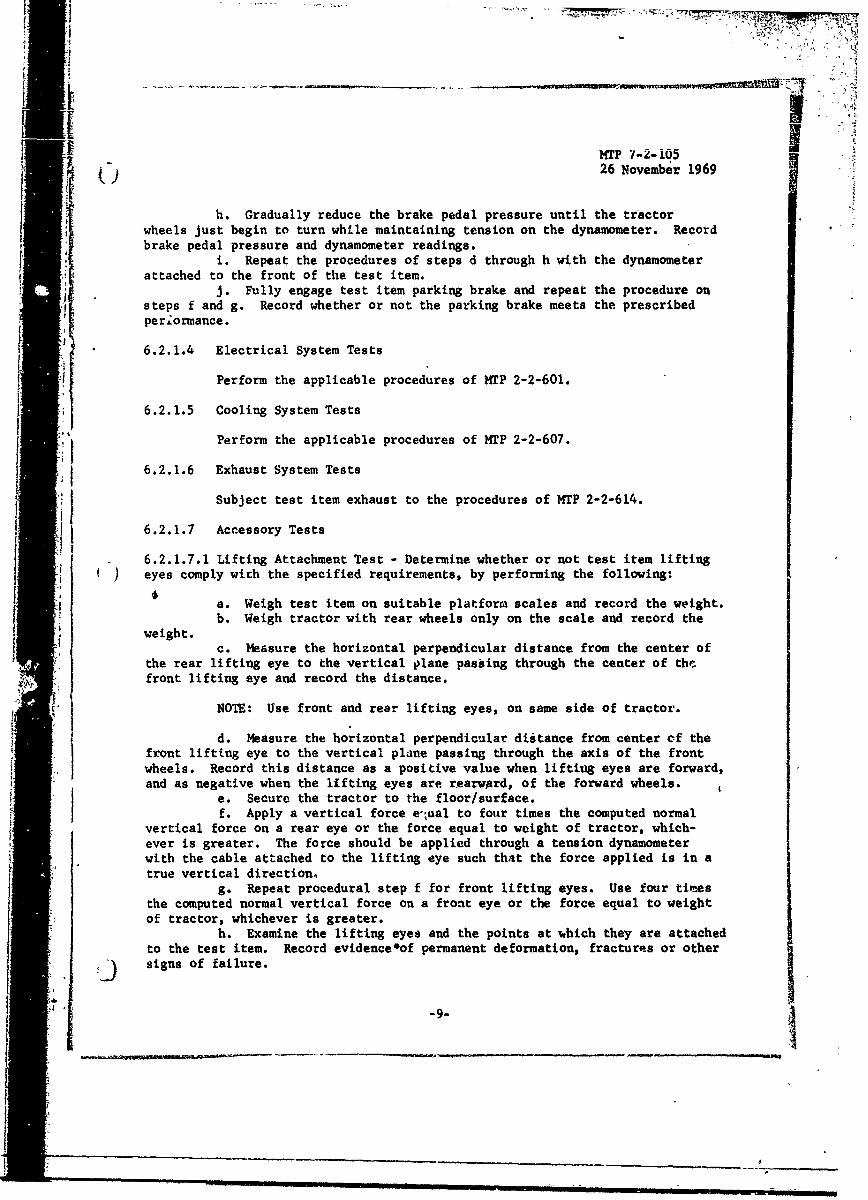
6.2.1.7 Accessory Tests
6.2.1.7.1 Lifting Attachment Test - Determine whether or not test item liftingI ) eyes comply wich the specified requirements, by performing the following:
a. Weigh test item on suitable platform scales and record the weight.b. Weigh tractor with rear wheels only on the scale and record the
weight.c. Measure the horizontal perpendicular distance from the center of
the rear lifting eye to the vertical plane passiing through the center of th',front lifting eye and record the distance.
NOTE: Use front and rear lifting eyes, on same side of tractor.
d. Measure the horizontal perpendicular distance from center of the.1 front lifting eye to the vertical plane passing through the axis of the frontwheels. Record this distance as a positive value when lifting eyes are forward,and as negative when the lifting eyes are rearward, of the forward wheels.
e. Secure the tractor to the floor/surface.f. Apply a vertical force equal to four times the computed normal
vertical force on a rear eye or the force equal to weight of tractor, which-ever is greater. The force should be applied through a tension dynamometerwith the cable attached to the lifting eye such that the force applied is in atrue vertical direction,
g. Repeat procedural step f for front lifting eyes. Use four timesthe computed normal vertical force on a front eye or the force equal to weightof tractor, whichever is greater.
h. Examine the lifting eyes and the points at which they are attachedto the test item. Record evidenceeof permanent deformation, fractures or other
jD signs of failure.
-9-

MTP 7-2-10526 November 1969 0
6.2.1.7.2 Kit Evaluation - Evaluate kits in accordance with MTP 2-2-707.
6.2.1.7.3 Personnel Heating and Ventilation System Evaluation - Perform theapplicable procedures of MTP 2-2-738.
6.2.1.7.4 Winch Evaluation - Perform the applicable procedures of MTP 2-2-712.
6.2.1.7.5 Generator Test - If the test item is equipped with a generator tosupply aircraft with electrical power, subject the generator to the applicableprocedures of MTP 9-2-136.
6.2.1.7.6 Compressor Test - If the test item is equipped with a compressor forstarting aircraft engines, subject the compressor to the applicable proceduresof HTP 9-2-166.
6.2.1.7.7 Stowage - Determine the adequacy of storage space provided for tools
and chock-blocks as directed in the applicable sections of MTP 2-2-802.
6.2.1.8 Power-Train Test
Perform applicable procedures of MTP 2-2-605.
6.2.2 Overall Tractor Performance Tests
Test the aircraft towing tractor as a unit or system by performingthe following:
6.2.2.1 Drawbar Pull Test
Determine whether the tractor being evaluated meets the ultimate draw-bar pull requirement, by performing the applicable procedures of MTP 2-2-604 and
j. the following:
a. Place the test item on a dry, level, brushed concrete surface.
NOTE: If the surface friction between the concrete and tractortires is less than 0.50, the surface may be brushed withabrasion compound or other material to provide a 0.90 co-efficient of friction.
b. Thermally stabilize the test item at standard ambient temperatureand record the temperature.
c. Measure and record barometric pressure at time of test and recordtest site altitude.
d. Attach the tractor pintle hook to an anchor of sufficient strengthto withstand a force equal to ten times the test item rated drawbar pull value.This connection is made with sections of steel cable or chain in series with adynamometer.
NOTE: The cable or chain anchor cosnection point should be at thesame height as the test items pintle hook connection.
_10-

-q 7 - 4 A l A
HTP 7-2-10526 Novembr 1969*
e. Inflate test item tires, with air only, to the specified orrecommended pressure.
f. Start and warm-up the tractor engine for fifteen minutes.g. Start tractor forward in low gear and slowly accelerate until the
dynamometer gauge reads maximum. Record the maximum drawbar pull value attained.h. Repeat step g. five times, with each operation separated by at
least one hour.i. If the test item did not attain the minimum specified drawbar
pull value, record observations of test team members as to why the test itemfailed.
6.2.2.2 Acceleration-Acceleration Response Test
Determine the acceleration characteristics of the test item, by per-forming the applicable procedures of MTP 2-2-602 and the following:
a. Place the test item on a dry, level, brushed concrete surface.b. Mark-off on the test surface an interval, "A-B", of specified
length for acceleration tests.c. Warm-up the tractor engine for fifteen minutes prior to testing.d. Locate the unloaded tractor with its front wheels at point "A".e. Locate at point "A" and at point "B" photoelectric switches which
are connected to a recently calibrated electronic timing device.f. With the tractor engine running at idle speed, the transmission
engaged, and the operator alerted, accelerate the test item at the maximumattainable speed from point "A" to point "B". Record the elapsed time.
g. Repeat step f. five times.h. Load the test item pintle with the rated trailing load. Repeat
the procedures of steps f. and g.it Place the test item with specified rated trailing load on level
surfaces with the engine running at idle speed, the transmission in low-speed,forward drive and the clutch shall be disengaged.
J. Arrange a timing device to be started simultaneously with theengagement of the clutch.
k. At a pre-arranged signal, the test item operator shall depressthe accelerator/engage the clutch (and start the timing device).
1. Observe the tractor closely. At the instant of tractor movement,the timing device shall be stopped and the elapsed time shall be recorded.
m. Repeat the procedures of steps k. and 1. five times.n. Repeat the procedures of steps k., 1., and m. for no-load condi-
tions.
6.2.2.3 Speed Test
Determine test item attainable speed on a level surface over a measureddistance, by performing the applicable procedures of MTP 2-2-602 and the follow-ing:
a. Place the test item on a dry, level, brushed concrete surface.b. Mark-off on the test surface three points, "A", "B", and "C".
__) The interval of "A-B" shall be equal to the distance required for the test item
-11-

I WM 7-2-10Sf26November 1969
to achieve maximum velocity; the interval "B-C" shall be equal to eighty-eightfeet. An automatic photoelectric timing device is connected to switches locatedat points "B" and "C".
NOTE: The eighty-eight foot length is used to simplify calculationssince eighty-eight feet per minute is equal to one mile perhour.
c. Thermally stabilize the test item at standard ambient temperatureand record the temperature.
d. Warm-up the tractor engine for fifteen minutes prior to testing.e. Start the tractor rut% without trailing load, from point "A".
Ensure that test item is operating in high gear at maximum attainable speed by
the time point "B' is passed. Repeat the proceltzre until five runs have beencompleted.
f. Record the elapsed time for test item to travel from point "B" topoint "C".
g. Perform the procedures of steps e. and L. for rearward direction.h. Attach the rated trailing load to the test item and perform the
procedures of steps, e. and f. (Do not attempt reverse testing of speed with aloaded test item),
6.2.2.4 Fuel Consumption Test
Perform applicable procedures of MTP 2-2-603. k
6.2.2.5 Turning Radius Test
Determine the minimum turning radius of the test item, by performing
the applicable procedures of MTP 2-2-609 and the following:
a. Place the test item on a level, dry, brushed concrete surface.b. Thermally stabilize the test item at standard ambient temperature.
Record the temperature value.c. Drive the tractor in full 360 degree turns to the right and to
the left. Complete five turns in each direction. Measure the turning radius.d. Record the turning radius for each trial to the right and left.
6.2.2.6 Gradeability and Side Slope Performance Test
Perform applicable procedures of MT? 2-2-610.
6.2.2.7 Fording Test
Perform applicable procedures of MTP 2-2-612.
6.2.2.8 Mobility Test
Perform applicable procedures of MTP 2-2-619.
6.2.2.9 Endurance and Durability Test
-12-
:- --|-------.-*--**-i-- i ... ,+ .--. .. .

mTP 7-2- •'.
()26 Kvec~iýx- -ý
Determine the endurance characteristics of the test item undercontrolled conditions while undergoing a 720 mile test circuit, by performingthe applicable procedures of MIL-STD-259C, and the following:
a. The test course shall be set up equivalent to the provisions ofAppendix A, Outdoor Course for Tractors.
b. The test course obstacles shall be-constructed in accordance withAppendix B, Obstacle Block Construction.
c. The test course shall be paved with concrete, asphalt, macadam,or equivalent, having a road resistance of 30 to 50 pounds per ton.
d. During conduct of the endurance test, the course should be dry,clean, and free of snow, ice, non-planned obstacles, or other foreign materials.
e. Testing shall be accomplished during daylight hours.f. The test item shall complete 1440 complete circuits of the test
course, with 12 circuits being equivalent to one hour of operation. The testvehicle shall traverse the endurance course at the maximum safe practical speed.
g. The following shall be accomplished during test item traverse ofthe endurance course:
1) Lights of the test item shall be illuminated at all times,except at the beginning of each lap when the light switchshall be turned "off" and "on" again.
2) Maintenance and inspections shall be performed in accordance
with the draft technical manual or after completion of each480 test course circuits.
"3) A trailing test load shall be connected to the test item forthe complete 1440 circuits except for maintenance and whennegotiating the obstacle blocks.
4) At the beginning of each lap, the operator shall sound thehorn for one second.
5) The test item ignition switch shall be turned off and on aftereach 12 (one hour) circuits.
6) On alternate days, the endurance test course shall be traversedin the opposite direction.
h, At the completion of the required number of circuits, the testitem should be given routine inspection and service in accordance with thedraft technical manual. A record of this inspection shall be kept; an exampleof a post-test inspection record form is provided by Figure 1.
NOTE: For each item listed vertically by Figure 1, five possibleinspection/action outcomes are listed horizontally:(1) Item OK, (2) Item Not OK, (3) Adjust, (4) Repair, and(5) Replace. Therefore, if outcome (2) is indicated,there should be a corresponding check of (3) or (4), or(5), as appropriate.
6.2.2.10 Broadband Radio Interference Test
Subject the test item to appropriate procedures of MIL-STD-462.
-;10
* -13-

I
1 " 47r--2-i0526 November 1969 CJ
FIGURE 1: POST-TEST INSPECTION FORM
INSTRUCTION: Examine each item below in sufficient detail to deter-mine any defects or excessive wear which have caused failure in test or mightcause failure in normal operation. Place a check mark in column No. 1 or No. 2.If column No. 2 is checked, also check column Nos. 3, 4, or 5.
G,) (2) (3) (4) (5)Not
Description OK OK Adjust Repair Replace
1. Batteries
2. Brakes
3. Clutch
4. Contactors
5. Cooling - Thermostat
6. Differential
7. Drive Axle
8. Drive Shaft and Universal
9. Electric Components (Electric tractor)
a. BatteryBlocking
F b. Contactor
c. Controller
d. Collector Ring
e. Foot Pedal Control
f. Interlock - Controller
g. Instruments
h. Limit Switch
i. Line Breaker
J. Plug and Receptacle ()
-14-

F ~mTP 7-2-105-t~26-Noveuber 1969 ,-
Figure 1: POST-TEST INSPECTION FORM - (Cont'd)
(1) (2) (3) -(4) (5)Not
Description OK OK Adjust. Repair Replace
k. Power Unit (Motors, etc.)
1. Resistors - Housing
m. Seat and Brake Switch
n. Speed Control
o. Wiring
10. Engine
11. Frame and Body
12. Fuel System (When Furnished)
13. Automatic Coupler
] 14. Instrumentation
15. Muffler (When Furnished)
16. Springs
17. Steering
18. Transmission
19. Torque Converter
20. Wheels"
NOTE: Place remarks opposite the proper number of the followingportion of this form. If more space is required, attachseparate sheet. Remarks should include details of adjustments,repairs, or replacements indicated by check marks above.
0-15-

J[ MIM 7-2-105
26"November 1969
6.2.2.11 Magnetic Permeability Property Test
Using a suitable magnetometer, measure and record the magnetic permea-bility properties at a specified fixed distance from all sides of the test item,to determine possible detrimental effects of the test item on aircraft naviga-tion components, e.g. compass. Measurements should be made under'the followingconditions:
a. Test item not in operationb. Test item engine idlingc. Test item engine operating at maximum rpmd. Generator or compressor operating, if applicable
6.2.3 Transportability Test
With the test item packaged or crated for transport as described inthe test item technical manual or manufacturer's instructions, subject thetest item to the following transportability tests:
"6.2.3.1 Surface Transportability
Subject the test item to the applicable procedures of 14TP 10-2-503less the simulated marine transportability tests.
6.2.3.2 Simulated Marine Transportability Tests ()
a. Load the test item aboard a suitable ship simulating facilitycapbleofsimulating actual ship loading conditions, hold and deck space, and
Adip's pitch ind roll, using normal materiel handling equipment and record the'following:
1) Ship type simulated2) Equipment used for loading3) Location of storage4) Difficulties encountered loading5) Materials used for securing
b. Apply a roll of 300, with a period of 30 seconds, and a pitch of5" with a period of 30 seconds, and a pitch of 5* with a period of 20 secondsfor a minimum of one hour and record the following:
1) Pitch and roll period2) Accelerometer recording readings3) Damage to test item or bracing
6.2.3.3 Air Transportability Tests
NOTE: The conduct of air transportability testing shall be coordin-ated with the appropriate unit conducting the air transporta-bility tests.
-- --- ---

[I. ... 'I wi.. .. -5•0.• •. 7..., 2•(• • ••...1fl • IIs, •
26 Novýmb i#169
Determine and reord the internal air transportability of the testitem as described in the applicable sections of NTP 7-2-515.
6.2.3.4 Logistics-Over-the-Shore (LOTS)
Determine the LOTS characteristics of the test item as described, inthe applicable sections of MrP 2-2-520 and the following:
a. Load the test item and a suitable towing vehicle aboird a landltgcraft from a ship anchored offshore using normal ships handiing equipment,couple the test item to the towing vehicle, and record the following:
1) Sea state and duration2) Wind direction and speed3) Equipment used for loading4) Difficulties encountered loading or coupling5) Materials used for securing6) Damage to test item or towing vehicle
b. Transport the test item to the shoreline, off-load and towthrough ser and surf up to 20 inches, including vehicle-sinkage depth and waveheight, for a minimum of 15 minutes. Tow the test item over the sand to apoint not less than two miles from the shoreline, and then disassemble, inspectand setup for normal operation. Determine the optimum tire pressures for boththe test item and the towing vehicle and record the following:
1) Water depth.2) Difficulties in towing.3) Test item and towing vehicle tire pressures.4) Any deficiencies in operation or damage to the components
of the test item.
c. Secure the test item for transport, tow it to the shoreline andreload it onto the landing craft by both driving and backing into the craft.Record any difficulties encountered in reloading or damage to the test item.
6.2.4 Maintenance
Evaluate the maintenance-related factors of the test item as describedin MIP 2-2-503 with emphasis on the following:
a. Organizational (0), Direct Support (F), and General Support (H)Maintenance requirements.
b. Operator through General Support Maintenance Literature.c. Repair parts.d. Tools.e. Test and I? ndling equipment.f. Calibrati n and maintenance facilitiesg. Personnel skill requirements.h. Maintainability.i. Reliability.
-17-
:1,!

Li 9
MTP 7-2-10526 November 1969
J. Availability.
6.2.5 Safety
Evaluate the safety characteristics of the test item in accordance withthe MTP 2-2-508 and MTP 10-2-508 and record the following, if applicable.
a. Any dangerous or unsafe condition or any condition that mightpresent a safety hazard including the cause of the hazard and steps taken toalleviate any such hazard.
b. Inadequate or inoperative safety features.c. Adequacy of warning instructions and markings.d. Suggestions to improve the existing safety precautions.
'6.2.6 Human Factors Evaluation
Evaluate the test item to determine the degree to which test itemphysical design and revealed performance. characteristics conform to recognizedhuman factors engineering design criteria, by performing the applicable proceduresof MTP 2-2-803 and the following:
a. Using the criteria of Human Factors Evaluation Data for GeneralEquipment (HEDGE) for Class IlA equipment, prepare check lists to evaluate thehuron factors characteristics in the following areas.
1) Controls and indicators:
a) Location: How easy to operate and readb) Markings: Clearly marked for function
2) Ease of operating and controlling test item.3) Performance characteristics which do not conform to recognized
human factors design criteria.4) For maintenance:
a) Ease of locating malfunctions and determination of causeb) Access to defective componentc) Ease of replacement and/or repair of malfunction
b. Evaluation of the tasks of step a, shall include, but not belimited to, the following:
1) Adequacy of furnished instructions2) Ease of performing tasks3) Human factors design deficiency revealed by particular test4) Time to perform task5) Personnel required for task
c. Record inadequacies of the test item design affecting ease ofvehicle operacion.
d. Ascertain noise levels utilizing criteria prescribed in HEL
-18-

7-T7 1177
S Standard S-l-63B, TB MED 251 and MIL STD 1472. MP--0 99
e. Record any recommendations to improve man-item effectiveness.
]6.2.7 Value Analysis
Throughout all tests, the test item shall be examined for any unnec-.essary, (, ',ly, or "nice-Lo-have" features as described in USATECOM Regulation700-1 by performing the following:) ~ a. During operation of the test item, observe for features wehich
could be eliminated without compromising performance, reliability, durability,Ior safety.b. Question test personnel regarding features of the teat item.
which could ba eliminated without decreasing the functional value of the testI j item or decrease man-item effectiveness.
c. Record the following:
1) Non-functional, costly, or "nice-to-have" features of thetest item.
2) Test personnel comments and opinions regarding features to beeliminated.
6.3 TEST DATA
6.3.1 Preparation for Test] j6.3.1.1 Initial InspectionjJ Record the following:
* ~a. Data collected or described in applicable sections of ?fTP 2-2-502.b. Evidence of damage or deterioratiton of test item or materials
used for protection during shipment.c. Identification markings which were not in accordance with
MIL-STD-129, MIL-STD-130, or test item detail specification.d. Evidence of defects in:
1) Manufacturing2) Material3) Workmanship
6.3.1.2 Inventory Check
Record the following:
a. Missing maintenance literature or draft technical manual(s).
tC) b.dr S hortages in repai parts acendres rL tTDols.c. Recording reokidtostospoe.a-te fetees
essary . Misn pats tools or "no-obae e there adecmpoed ntso UtheO manenanc on
-19-
AI
a. Drin opratin o th tet itm, bseve or fatues hic
r
MTP 7-2-10526 November 1969
6.3.1.3 Inspection and Preliminary Operation
Record the following:
a. Data collected as described in applicable section of MTP 2-2-502.b. Data collected as described in applicable section of MTP 2-2-505.
6.3.1.4 Pre-Test Evaluation
6.3.1.4.1 Reciprocating Internal Combustion Engine Tests -
Record data collected as described in the applicable sections ofHTP 2-2-700.
6.3.1.4.2 Power Train Component Tests
Record data collected as described in the applicable sections ofHTP 2-2-703.
6.3.1.4.3 Tire Tests -
Record data collected as described in the applicable section ofNTP 2-2-704.
6.3.1.5 Physical Characteristics
Record the following:
a. Data collected as described in the applicable section ofMTP 2-2-500 including the following:
1) Engine make and model2) Test item length, less coupler(s), in inches3) Width, in inches4) Height, less cab, in inches5) Wheelbase, in inches6) Ground clearance, in inches7) Governed speed, in miles per hour8) Gross vehicle weight, in pounds
b. Counterweight information.c. Drive-steer provisions.d. Aircraft service facilities provided (starting compressor,
generator, etc.)e. Safety equipment supplied.f. For center of gravity.
1) Vertical distance in inches from drive axle2) Horizontal distance in inches from drive axle
-20-

'I
(~~~~) 26 No~qie* ;L.*
6.3.1.6 Operator Training and Familiarization
Record data collected as described in MTP 10,2-501..
6.3.2 Test Conduct
6.3.2.1 Subsystem Tests
6.3.2.1.1 Clutch Pedal Test -
Record the following:
a. Test site temperature at time of test, in degrees F.
b. Maximum force required to depress the clutch (engine not running),in pounds.
c. Maximum force required to depress the clutch pedal, (engine on),in pounds.
d. Characteristics of clutch pedal operation which differed withengine rut.aing.
6.3.2.1.2 Steering Wheel Test-
Record the following:
a. Data collected as described in the applicable sections of
MTP 2-2-609.
b. Temperature at time of test, in degrees F.c. Maximum gauge reading at extreme end of clockwise steer range, in
pounds.
d. Maximum gauge reading at extreme end of counterclockwise steerrange, in pounds.
e. Following application of specified force to steering mechanism
with steerable wheel(s) locked, list any damage or evidence of failure/permanentdeformation:
1) Force applied clockwise2) Force applied counterclockwise
f. Number of turns of the hand steering wheel to move the steerwheels from one extreme position to the other.
6.3.2.1.3 Brake Tests -
Record data collected as described in the applicable sections ofMTP 2-2-608 and the following:
a. Test site temperature, in degrees F.b. Fur the service brakes:
1) End of the vehicle to which the dynamomete: is attached(front, rear).
-21-
I _

MTP 7-2-10526 November 1969
2) Brake force required to produce specified dynamometer tension,in pounds.
3) Measurements, just as wheels of the test ilem start to turn:
a) Tension on the dynamometerb) Force applied to brakes, in poundsc) For the parking brakes:
1) Tension produced on the dynamometer2) Force applied to brakes, in pounds3) Adequacy of parking brakes
6.3.2.1.4 Electrical System Tests -
Record data collected as des~cribed in the applicable sections ofMTP 2-2-601.
6.3.2.1.5 Cooling System Tests
Record data collected as described in the applicable sectionsof•i MTP 2-2-607.
6.3.2.1.6 Exhaust System Tests
Record data collected or described in the applicable sections of IMTP 2-2-614.
6.3.2.1.6 Accessory Tests -
"ii 9 a. Lifting Attachment Test - Record the following:
1) Test item weight (test item only), in pounds.
2) The test item weight with only rear wheels on the scale, inpounds.
3) Horizontal perpendicular distance from th center of the rearlifting eye to the vertical plare passing ttihrough the centerof the front lifting eye, in inches.
4) Horizontal perpendicular distance from center of the front
lifting eye to the vertical plane passing through the axisof the front wheels, in inches. (When this distance isforward of the lifting eye record as positive, and negativewhen dtstance is to the rear of the eye).
5) Following application of the test force, list any evidence ofdamage to the lifting eye(s) and the pcints where connectionis ma&• •- the test item.
b. Kit Evaluation - Record data collected as described in the applicableprocedures of MTP 2-2-707.
c. Personnel Heating and Ventilation System Evaluation - Record datacollected as described in the applicable sections of MTF 2-2-708.
-22-
__________ __________________________

MTP 7-2-10526 Noyenber l9. 9"
d. Winch Evaluation - Record data collected as described in theapplicable sections of MTP 2-2-712;
e,. Generator Test - Record data collected as descri6ed in theapplicable sections of MTP 9-2-136.
f. Compressor Test - Record data collected as described in theapplicable sections of MTP 9-2-166.
g. Stowage - Record data collected as 'described in the applicablesections of MTP 2-2-802.
6.3.2.1.8 Power-Train Test
Record data collected as described in the applidable sections ofMTP 2-2-605.
6.3.2.2 Overall Tractor Performance Tests
6.3.2.2.1 Drawbar Pull Test -
Record data collected as described in the applicable sections, ofMTP 2-2-604 and the following:
a. Test site temperature at time of test, in degrees F.b. Barometric pressure, in inches of Hg.c. Test site altitude, in feet above sea level.d. Maximum drawbar pull value attained, in pounds.e. Test team comments regarding test item and reasons for not
attaining required drawbar pull, when applicable.
6.3.2.2.2 Acceleration-Acceleration Response Test - -
Record data collected as described in the applicable sections ofMTP 2-2-602 and the following:
a. Acceleration distance (A-B), in feet and inches.
b. Time required for test item to traverse A-B, for each run, inseconds.
1) Without load2) Pulling rated load
c. Test item acceleration response time, fully loaded, in seconds.d. Test item acceleration response time, not loaded, in seconds.
6.3.2.2.3 Speed Test -
Record data collected as described in the applicable sections ofMTP 2-2-602 and the following:
a. Test site temperature at time of test, in degrees F.
-23-

I j
I WMI. 7-2-105"26 'ovember 1969 (.
b. Elapsed time for test item to traverse an eighty-eight footinterval at maximum speed, in seconds:
I) In the forward direction
a) With no load
b2 a) With towed load
2) In the reverse direction
6.3.2.2.4 Fuel Consumption Test -
Record data collected as described in the applicable sections ofMTP 2-2-603.
6.3.2.2.5 Turning Radius -
Record data collected as described in the applicable sections ofWMP 2-2-609 and the following:
a. Test site temperature, in OFb. Test item turning radius:
1) To the right2) To the left
6.3.2.2.6 Gradeability and Side Slope Performance Test -
Record data collected as described in the applicable sections ofTtP 2-2-6e0.
6.3.2.2.7 Fording Test -
Record data collected as described in the applicable sections ofMWP 2-2-612.
6.3.2.2.8 Mobility Test -
Record data collected as described in the applicable sections ofMTP 2-2-619.
6.3.2.2.9 Endurance and Durability Test -
a. Record data collected as described in the applicable sections ofMITP 2-2-506.
b. Retain completed Post-Test Inspection Forms.
6.3.2.2.10 Broadband Radio Interfe~ence Test -
Record data collected as described in the applicable procedures ofMIL-STD-462.
-24-

MT1 7-2-1054') 26 November 1969
6.3.2.2.11 Magnetic Permeability Property Test -
Record the following:
a. Magnetic permeability properties on all sides of the test item:
1) With the test item not in operation2) With the test item idling3) With the engine operating at maximum rpm4) With the generatoc or compressor operating, if applicable
b. The distance at which measurements were made, in feet
6.3.2.3 Transportability Test
6.3.2.3.1 Preparation for Test -
Record data collected as described in the applicable sections ofMfP 10-2-503.
6.3.2.3.2 Land Tests -
Record highway transportability data collected as described in theapplicable sections of HTP 10-2-503.
6.3.2.3.3 Marine Tests -
Record the following:
a. Ship type simulatedb. Equipment used for loadingc. Location of storaged. Difficulties encountered loadinge. Materials used for securingf. Pitch and roll period, in secondsg. Accelerometer recording readings, in G'sh. Damage to test item or bracing
6.3.2.3.4 Air Transportability Tests -
Record data collected as described in the applicable sections ofMTP 7-2-515.
6.3.2.3.5 LogIstics-Over-the-Shore (LOTS) -
Record the following:
a. Data collected as described in the applicable sections ofMTP 2-2-520.
b. During loading:
* -25-: ,4

MTP 7-2-10526 November 1969
1) Sea state (1, 5, etc.) and duration, in seconds2) Wind direction and speed, in "knots3) Equipment used for ioading4) Difficulties encountered loading or coupling'
)Materials used for securing6) *Dimage to test item'or 'towing vehicle
c. During off-loading and towing Poerations:
1) Water depth, in inches.2) Difficulties in towihg.3) Test item and towing vehicle tire pressures, psi.4) Any deficiencies in operation or damw3e to the components of
the test item.
d. During reloading operations:
1) Difficulties encountered reloading2) Damage to the test item
6.3.2.4 Maintenance
Record data as collected as described in the applicable sections ofMP 2-2-503.
e•.3.2.5 Safety
Record data collected as described in the applicable sections of
MTP 2-2-508, MTP 10-2-508 and the following:
a. Any condition that mt.ght present a safety hazardb. Cause of the hazardc. Steps taken to remedy the hazardd. Inadequate or inoperative' safety featurese. Adequacy of warning instructions and warningsf. Suggestions to improve the man-item effectiveness
6.3.2.6 Human Factors Evaluation
a. Record data collected as described in the applicable sections ofMIP 2-2-803 and the following:
1) Inadequacies of the test item design affecting ease of vehicleoperation.
2) Noise levels which exceed the safe limit as described inTB-lM) 251.
3) Suggestions to improve the existing safety precautions.
b. Retain completed HEfiGE checklists.C
6.3.2.7 Value Analysis
-26-

_FR ýM 7
4)26 'Nov'ember 1969
Record the following:
a. Non-functional, costly, or "nice-to-have" features of the test 11Vitem.
b. Test Personnel comments and opinions regarding features to'beeliminated.
6.4 DATA REDUCTION AND PRESENTATION
Data obtained during conduct of the engineering tests shall be sum-marized, making use of curves, charts, photographs, or other graphic materials,,as appropriate. -- _ a
Data obtained for each test item performance characteristic shall becompared with technical performance characteristics specified in applicableQMR's, SDR's,or other development criteria.
In addition, the data presentation shall include written, narrativereports on all tests specified by this document.
A Safety Release Recommendation shall be submitted in accordance withUSATECOM Regulation 385-6 based on the data collected, related to safety.
-27-

MTP 7-2-10526 November 1969
APPENDIX A
ENDURANCE AND DURABILITY TEST COURSE DESIGN
5 0'
540 B,
11 I
54500
i ~Point:
'• ~Unde_..r
iiLoad
2010-
.1i.
OBSTACLETEST
A-1
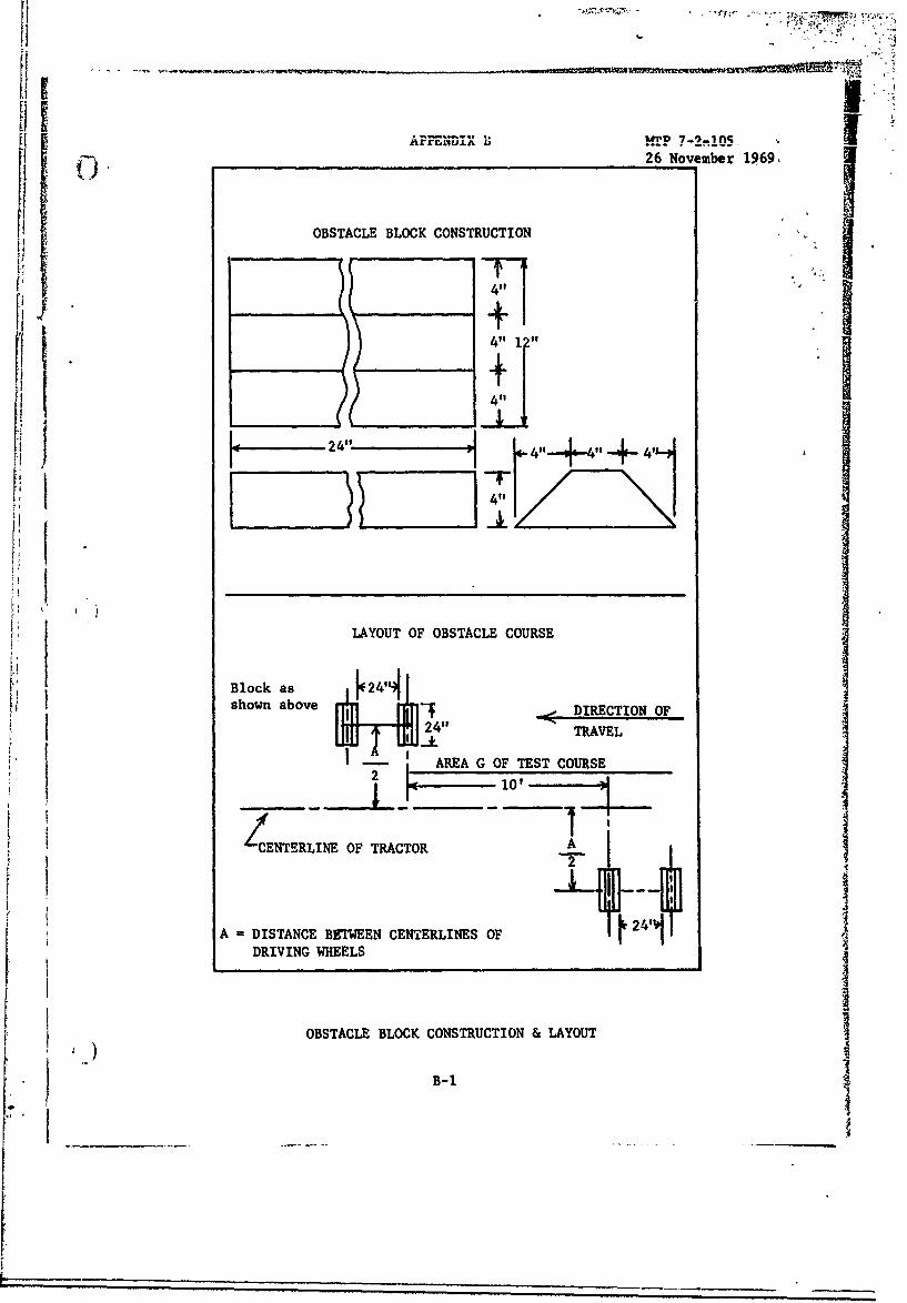
APPENDIX i !!TP 7-2-n05-26 November 1969,
OBSTACLE BLOCK CONSTRUCTION
+1'4 11I
411
LAYOUT OF OBSTACLE COURSE
Block as 24"shown above DIRECTION OF
2411 TRAVEL
AREA G OF TEST COURSE2 L io,
CENTERLINE OF TRACTOR A2
A DISTANCE BETWEEN CENTERLINES OF .241
DRIVING WHEELSIIOBSTACLE BLOCK CONSTRUCTION & LAYOUT
B-i1

MTP 7-2-10526 November 1969
UNCLASSIFIEDSec'intv Cla.-fication
DOCUMENT CONTROL DATA. R & DSIeraell jo firAlton of liii., hod, of ah~trarl and indexing annotntion -uxt be enfeted % then (i uv•', ll report i% ch. ~uIIC.Vll
I ORIGINATING ACTIVITY lColpolale 0 eu4 o) 2-. REPORT SECURITY CLASSIFICATION
US Army Test and Evaluation Command (USATECOM) UnclassifiedAberdeen Proving GrounA, Maryland 21005 2b. GROUP
2 REPORT TITLE
US Army Test and Evaluation Command Materiel Test Procedure 7-2-105,Commodity Engineering Test Procedure, - "Tractor, Wheeled, Aircraft, Towing."
4. DESCRIPTIVE NOTES (Type of report Andinclusive dates)
FinalS. AUTHORIS) (First name, middle Iniltiel, lfel name)
6 IMPORT OATE 78. TOTAL NO. OF PAGES 7b. NO. OF REFS
26 November 1969 34 51Ce. CONTRACT OR GRANT NO. 5* ORIGINATOR'S REPORT NUMBER(S$"' ~DA*18"00 t-AMC-1045 (R)
b. PROJECT NO. MTP 7-2-105AMCR 310-6
C. 9b. OTHER REPORT NOIS) (Any other numbers that may be .ealinedthis report)
30. OISTRIBUTION STATEMENT
This document is subject to special export controls and each transmittal toforeign governments or foreign nationals,-WITH THE EXCEPTION OF AUSTRALIA,CANADA, AND UNITED KINGDOM,-may be made only with prior approval of HQ,JSATECOM.
II- SUPPLEMENTARY NOTES 12, SPONSORING MILITARY ACTIVITY
I Headquarters" ------------- IUS Army Test and Evaluation Command
AAberdeen Proving Ground, Maryland 2100513. ABSTRACT
This Engineering Test Procedure describes test methods and techniques for evaluat-ing the technical performance and characteristics of Aircraft Towing Tractors(Wheeled Type) and for determining the suitability of the test item to besubjected to service testing. The evaluation is related to criteria expressed inapplicable Qualitative Materiel Requirements (QMR), Small Development Requirements(SDR), Technical Characteristics (TC), and other appropriate design requirementsand specifications. ( "
I
IIIf OR A~ IPG 1)1•*O DDI NOV J473 (AGE 1) UNCLASSIFIEDS/N 010"1-807-6811 Security Classification A-31408
C-1
..... .1!

MTP 7-2-10526 November 1969
UNCLASSIFIED~,.uiI~Cli~.i I I nI
14.LINK A L€ •.INK • .S•/•I
KEV WOROS " ýI
ROLE IT ROLE WT ROLE IT
Engineering Test
Aircraft Towiag Tractor (Wheeled Type)
le ' Procedures
"rest Methods and Techniques
2)
DD FoM s, 1473 (BACK)
4 ' N@V 0115762 7JNCLASSIFIED* N 'N0O01-*07-682I Security Classification A-3140 ,
C-2