UK Flat Roofs - Recticel Insulation
36
UK Flat Roofs Specification Guide
Transcript of UK Flat Roofs - Recticel Insulation

UK Flat RoofsSpecification Guide
2
Flat Roofs Specification Guide
Sales: 01782 590480 | Technical Freephone: 0800 0854079 | recticelinsulation.co.uk
Recticel Insulation – your partner in comfort 3
Feel good inside 4
Recticel – high performance in flat roofs 5
6
8
10
12
14
Typical installation 17
Mechanically fixed single ply membrane 19
Adhered single ply membrane 20
Pour & roll /built-up felt 21
Torch-on felt 22
Mastic asphalt 23
Typical installation of ply-faced insulation board 24
Typical installation of vacuum insulation panel 25
Single layer tapered roof systems 28
Building regulations 29
The sustainable solution 31
Technical support 33
Product characteristics 35
Contents

Flat Roofs Specification Guide
Sales: 01782 590480 | Technical Freephone: 0800 0854079 | recticelinsulation.co.uk 3
Recticel Insulation – your partner in comfortAs well as producing PIR products of unparalleled quality, Recticel Insulation is a company of thought leaders and creators, driven by a desire to develop insulation which establishes unprecedented levels of thermal performance and usability. Based at its state-of-the art facility in Stoke-on-Trent, Recticel Insulation – which is part of the Recticel Group, one of the world’s largest producers of polyurethane products – is a committed solution-provider: an industry pioneer in the quest for future generations to be able to enjoy a sustainable environment, without compromising on comfort.
Much of our lifetime will be spent at home and in the workplace. Therefore, ensuring both areas are well-insulated is of the upmost importance. By creating a healthy interior climate, we enhance the well-being of those within. Customer comfort lies at the heart of Recticel Insulation’s success – and there can be no greater achievement than its facilitation of safe, secure and sustainable living space.
Insulating a building is a once-in-a-lifetime investment, hence the need to select PIR products of proven quality to help reduce long-term energy consumption - a major contributor to lowering carbon emissions and meeting the challenge of global warming. Renowned as a leading technical innovator within the insulation industry, Recticel is focused on the future needs of our children and guiding them towards a comfortable and worry-free future. Its worldview displays similar compassion. Recticel’s products are designed and
manufactured to result in the lowest environmental impact, and its Stoke-on-Trent site has attained ISO 14001 certification for its environmental management system.
In order to maintain its reputation as instigators par-excellence in the field of insulation advancement, Recticel’s search for new and improved product solutions continues daily at its Belgium-based Sustainable Innovation Department. From its high-specification European facility, a dedicated research and development team works tirelessly to discover formulas which will lead to the manufacture of materials comprising even greater thermal efficiency and workability. Quality product producers, unbeatable service providers, environmental engagers, future solution suppliers… Recticel Insulation has more than earned its position as one of the world’s leading PIR manufacturers – but its journey has only just begun.
Visit recticelinsulation.co.uk to view detailed product guides, including U-value calculations, or contact Recticel Technical Services Department on 0800 0854079 or our Sales Department on 01782 590480 to discuss your requirements.

4
Flat Roofs Specification Guide
Sales: 01782 590480 | Technical Freephone: 0800 0854079 | recticelinsulation.co.uk
As your insulation partner, we work together to create a feel good inside climate by providing a range of intelligent insulation solutions. By constantly innovating and improving our products we want to increase comfort for you and your customers. Discover the many ways you benefit from insulating with Recticel Insulation:
Stable inside temperature
Recticel Insulation guarantees maximum comfort by creating a living or working environment with a healthy and stable inside climate.
Quick installation
The boards are user friendly and comfortable to install. They reduce the installation time on site.
Lightweight
The insulation boards are light and easy to handle.
Easy to cut
Our boards are easy to cut on site in different dimensions. This gives you the ability to customise sizes to fit every project.
MAX
MAX
MAX
MAX
More living space
With their high insulation values, the insulation boards give you the opportunity to install thinner layers of insulation and create extra living space.
MAX
Feel good inside

Flat Roofs Specification Guide
Sales: 01782 590480 | Technical Freephone: 0800 0854079 | recticelinsulation.co.uk 5
RecticelHigh performance in flat roofs
All our PIR products are available in a wide choice of thicknesses, with low thermal conductivity and high compressive strength. Crucially, our insulation boards can assist in meeting the required thermal regulations in new build and refurbishment projects.
We manufacture PIR insulation boards that are the ideal solution across a variety of flat roofing applications, including single ply membranes, built-up felt, torch-on felt and mastic asphalt, with either concrete, steel or timber decks. Through our sister company, Gradient, we also work closely with our customers to design, manufacture and advise on the installation of bespoke, single layer tapered roofing solutions. As experts in single layer tapered roofing solutions, Gradient offers unparalleled technical expertise to ensure your bespoke roofing solution is the most efficient, economical and cost effective solution for the project
6
Flat Roofs Specification Guide
Sales: 01782 590480 | Technical Freephone: 0800 0854079 | recticelinsulation.co.uk
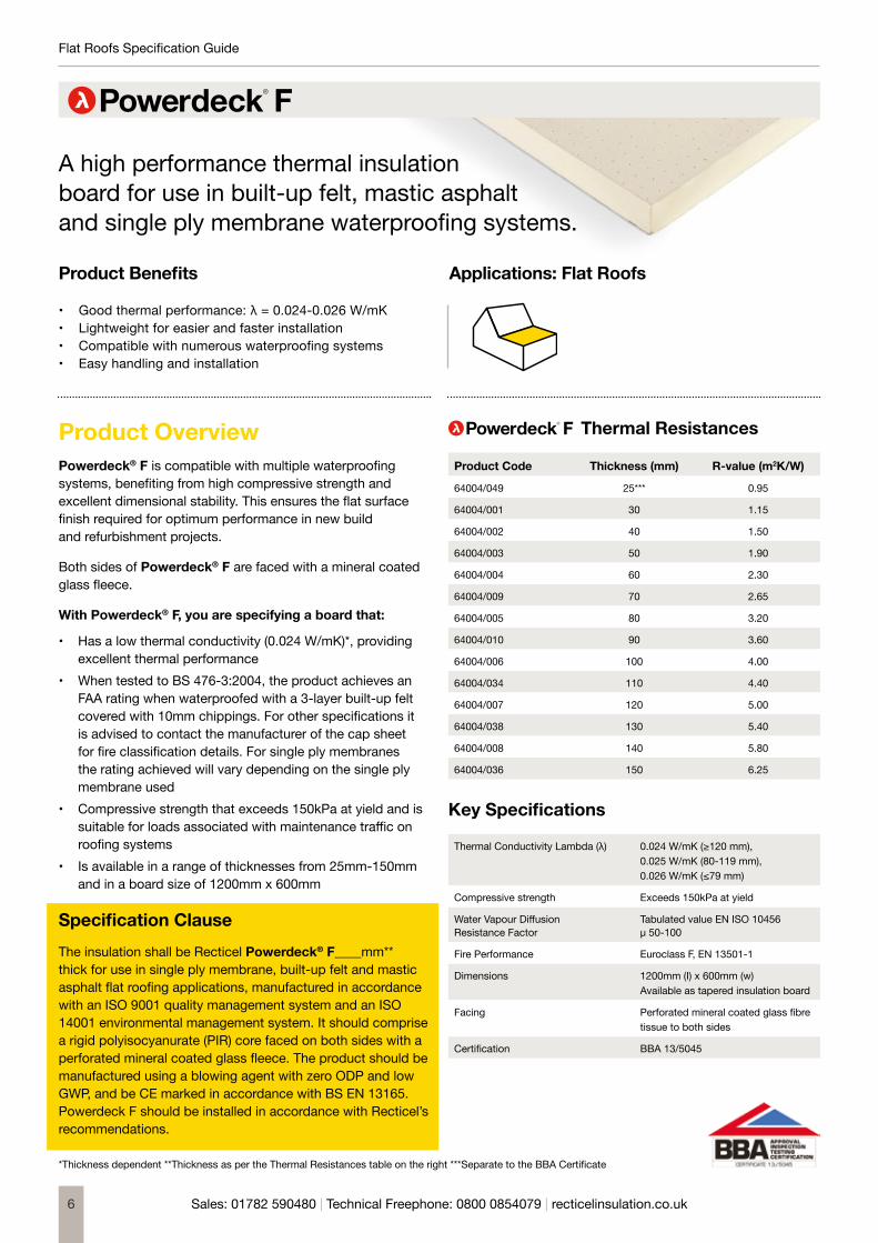
A high performance thermal insulation board for use in built-up felt, mastic asphalt and single ply membrane waterproofing systems.
Product Benefits
• Good thermal performance: λ = 0.024-0.026 W/mK • Lightweight for easier and faster installation • Compatible with numerous waterproofing systems • Easy handling and installation
Applications: Flat Roofs
MAX
Product OverviewPowerdeck® F is compatible with multiple waterproofing systems, benefiting from high compressive strength and excellent dimensional stability. This ensures the flat surface finish required for optimum performance in new build and refurbishment projects.
Both sides of Powerdeck® F are faced with a mineral coated glass fleece.
With Powerdeck® F, you are specifying a board that:
• Has a low thermal conductivity (0.024 W/mK)*, providing excellent thermal performance
• When tested to BS 476-3:2004, the product achieves an FAA rating when waterproofed with a 3-layer built-up felt covered with 10mm chippings. For other specifications it is advised to contact the manufacturer of the cap sheet for fire classification details. For single ply membranes the rating achieved will vary depending on the single ply membrane used
• Compressive strength that exceeds 150kPa at yield and is suitable for loads associated with maintenance traffic on roofing systems
• Is available in a range of thicknesses from 25mm-150mm and in a board size of 1200mm x 600mm
Specification ClauseThe insulation shall be Recticel Powerdeck® F____mm** thick for use in single ply membrane, built-up felt and mastic asphalt flat roofing applications, manufactured in accordance with an ISO 9001 quality management system and an ISO 14001 environmental management system. It should comprise a rigid polyisocyanurate (PIR) core faced on both sides with a perforated mineral coated glass fleece. The product should be manufactured using a blowing agent with zero ODP and low GWP, and be CE marked in accordance with BS EN 13165. Powerdeck F should be installed in accordance with Recticel’s recommendations.
Thermal Resistances
Product Code Thickness (mm) R-value (m2K/W)
64004/049 25*** 0.95
64004/001 30 1.15
64004/002 40 1.50
64004/003 50 1.90
64004/004 60 2.30
64004/009 70 2.65
64004/005 80 3.20
64004/010 90 3.60
64004/006 100 4.00
64004/034 110 4.40
64004/007 120 5.00
64004/038 130 5.40
64004/008 140 5.80
64004/036 150 6.25
Key Specifications
Thermal Conductivity Lambda (λ) 0.024 W/mK (≥120 mm),0.025 W/mK (80-119 mm),0.026 W/mK (≤79 mm)
Compressive strength Exceeds 150kPa at yield
Water Vapour Diffusion Resistance Factor
Tabulated value EN ISO 10456 μ 50-100
Fire Performance Euroclass F, EN 13501-1
Dimensions 1200mm (I) x 600mm (w) Available as tapered insulation board
Facing Perforated mineral coated glass fibre tissue to both sides
Certification BBA 13/5045
*Thickness dependent **Thickness as per the Thermal Resistances table on the right ***Separate to the BBA Certificate

Flat Roofs Specification Guide
Sales: 01782 590480 | Technical Freephone: 0800 0854079 | recticelinsulation.co.uk 7
Thermal PerformanceTypical U-values (W/m2K) achieved in common flat roof constructions
Warm Flat Roof
Waterproofing
Recticel Powerdeck® F
Vapour control layer
Structural deck Timber deck: 18mm ply Concrete deck: 150mm high density concrete Metal deck: unsealed galvanised steel deck
Ceiling Timber deck: 150mm joists with plasterboard finish Concrete and metal decks: 50mm timber battens with plasterboard finish
Powerdeck FProduct Thickness
(mm)Timber Deck Metal and Concrete Deck
Ceiling (W/m²K) No Ceiling (W/m²K) Ceiling (W/m²K) No Ceiling (W/m²K)
60 0.35 0.39 0.37 0.41
70 0.31 0.34 0.32 0.35
75 0.29 0.32 0.31 0.33
80 0.27 0.29 0.28 0.30
90 0.24 0.26 0.25 0.27
100 0.22 0.23 0.23 0.24
110 0.20 0.21 0.21 0.22
120 0.18 0.19 0.19 0.19
130 0.17 0.18 0.17 0.18
140 0.16 0.16 0.16 0.17
150 0.15 0.15 0.15 0.16
160 (80+80) 0.14 0.15 0.15 0.15
165 (90+75) 0.14 0.15 0.14 0.15
170 (90+80) 0.14 0.14 0.14 0.14
180 (90+90) 0.13 0.13 0.13 0.14
190 (100+90) 0.12 0.13 0.13 0.13
200 (100+100) 0.12 0.12 0.12 0.12
210 (120+90) 0.11 0.11 0.11 0.11
220 (120+100) 0.10 0.11 0.11 0.11
230 (130+100) 0.10 0.10 0.10 0.10
240 (120+120) 0.10 0.10 0.10 0.10

8
Flat Roofs Specification Guide
Sales: 01782 590480 | Technical Freephone: 0800 0854079 | recticelinsulation.co.uk
A high performance thermal insulation board for use in warm flat roofs with torch-on felt.
Product Benefits
• Good thermal performance: λ = - 0.024 - 0.026 W/mK • High compressive strength• Compatible with numerous torch applied waterproofing systems• Easy handling and installation• Durability
Applications: Flat Roofs
MAX
Product OverviewPowerdeck® U is a high performance rigid PIR insulation board for use in warm flat roofs with bituminous torch-on felt waterproofing systems. Its optimum stability, strength and structural integrity allows for the flattest finish. Combined with its precision-cut dimensions, your installation is quicker, easier and more cost effective. Powerdeck® U is also available in tapered forms to assist roof drainage.
With Powerdeck® U, you are specifying a board that:• Has a low thermal conductivity value (0.024 W/mK)*,
providing an excellent thermal performance • When tested to ENV 1187:2002 Test 4, it achieves a
BROOF (t4) rating on a plywood deck and with an IKO SBS Gold Seal cap sheet. For other specifications, contact the manufacturer of the waterproofing
• Compressive strength exceeds 150kPa at yield• Limited moisture absorption
Specification ClauseThe insulation shall be Recticel Powerdeck® U ____mm thick** for use in torch-on felt flat roofing applications, manufactured in accordance with an ISO 9001 quality management system and an ISO 14001 environmental management system. It should comprise a rigid polyisocyanurate (PIR) core faced on both sides with a bituminous glass fleece. The product should be manufactured using a blowing agent with zero ODP and low GWP, and be CE marked in accordance with BS EN 13165.
Thermal Resistances
Product Code Thickness (mm) R-value (m2K/W)
64602/001 30 1.15
64602/015 40 1.50
64602/016 50 1.90
64602/017 60 2.30
64602/018 70 2.65
64602/019 80 3.20
64602/020 90 3.60
64602/021 100 4.00
64602/023 120 5.00
64602/024 130 5.40
64602/025 140 5.80
64602/026 150 6.25
Key Specifications
Thermal Conductivity Lambda (λ) 0.024 W/mK (≥120 mm),0.025 W/mK (80-119 mm),0.026W/mK (≤79 mm)
Compressive strength Exceeds 150kPa at yield
Water Vapour Diffusion Resistance Factor
Tabulated value EN ISO 10456 μ 50-100
Fire Performance Euroclass F, EN 13501-1
Dimensions 1200mm (I) x 600mm (w) Available as tapered insulation board
Facing Perforated mineral coated glass fibre tissue to both sides
Certification BBA 13/5045
13/5045*Thickness dependent **Thickness as per the Thermal Resistances table on the right

Flat Roofs Specification Guide
Sales: 01782 590480 | Technical Freephone: 0800 0854079 | recticelinsulation.co.uk 9
Thermal PerformanceTypical U-values (W/m2K) achieved in common flat roof constructions
Warm Flat Roof
Waterproofing
Recticel Powerdeck® U
Vapour control layer
Structural deck Timber deck: 18mm ply Concrete deck: 150mm high density concrete Metal deck: unsealed galvanised steel deck
Ceiling Timber deck: 150mm joists with plasterboard finish Concrete and metal decks: 50mm timber battens with plasterboard finish
Powerdeck UProduct Thickness
(mm)Timber Deck Metal and Concrete Deck
Ceiling (W/m²K) No Ceiling (W/m²K) Ceiling (W/m²K) No Ceiling (W/m²K)
60 0.35 0.39 0.37 0.41
70 0.31 0.34 0.32 0.35
75 0.29 0.32 0.31 0.33
80 0.27 0.29 0.28 0.30
90 0.24 0.26 0.25 0.27
100 0.22 0.23 0.23 0.24
110 0.20 0.21 0.21 0.22
120 0.18 0.19 0.19 0.19
130 0.17 0.18 0.17 0.18
140 0.16 0.16 0.16 0.17
150 0.15 0.15 0.15 0.16
160 (80+80) 0.14 0.15 0.15 0.15
165 (90+75) 0.14 0.15 0.14 0.15
170 (90+80) 0.14 0.14 0.14 0.14
180 (90+90) 0.13 0.13 0.13 0.14
190 (100+90) 0.12 0.13 0.13 0.13
200 (100+100) 0.12 0.12 0.12 0.12
210 (120+90) 0.11 0.11 0.11 0.11
220 (120+100) 0.10 0.11 0.11 0.11
230 (130+100) 0.10 0.10 0.10 0.10
240 (120+120) 0.10 0.10 0.10 0.10

10
Flat Roofs Specification Guide
Sales: 01782 590480 | Technical Freephone: 0800 0854079 | recticelinsulation.co.uk
A high performance thermal insulation board for use in warm flat roofs under mechanically fixed single ply membrane systems.
Product Benefits
• Good thermal performance: λD = 0.022 W/mK• High compressive strength• Compatible with various single ply waterproofing systems• Easy handling and installation• Durability
Applications: Flat Roofs
MAX
Product OverviewEurothane® Eurodeck is compatible with mechanically fixed single-ply systems, benefiting from high compressive strength and excellent dimensional stability that ensures the flat surface finish required for optimum performance in new build and refurbishment projects. It is faced on both sides with a multi-layer coated aluminum foil.
With Eurothane® Eurodeck, you are specifying an insulation board that:
• Has a low thermal conductivity (0.022 W/mK) providing an enhanced thermal performance
• Compressive strength exceeds 150kPa at yield• Has Class 1 fire performance in accordance with
BS 476 (Part 7)• Limited moisture absorption
Specification ClauseThe insulation shall be Recticel Eurothane® Eurodeck ____mm thick* for use in single ply membrane flat roofing applications, manufactured in accordance with an ISO 9001 quality management system and an ISO 14001 environmental management system. It should comprise a rigid polyisocyanurate (PIR) core faced on both sides with a gas tight multilayer composite aluminium foil facing. The product should be manufactured using a blowing agent with zero ODP and low GWP, and be CE marked in accordance with BS EN 13165. Eurothane® Eurodeck should be installed in accordance with Recticel’s recommendations.
Thermal Resistances
Product Code Thickness (mm) R-value (m2K/W)
64685/013 25 1.10
64685/019 30 1.35
64685/001 40 1.80
64685/002 50 2.25
64685/003 60 2.70
64685/004 70 3.15
64685/015 75 3.40
64685/005 80 3.60
64685/006 90 4.05
64685/007 100 4.50
64685/008 110 5.00
64685/009 120 5.45
64685/010 130 5.90
64685/011 140 6.35
64685/017 150 6.80
64685/070 160 7.25
Key Specifications
Thermal Conductivity Lambda (λ) 0.022 W/mK
Compressive strength Exceeds 150kPa at yield
Water Vapour Diffusion Resistance Factor
Tabulated value EN ISO 10456 μ 50-100
Specific Heat Capacity 1.4kJ/kgK
Fire Performance Euroclass F, EN 13501-1 Class 1 BS 476 (Part 7)
Dimensions 2400mm (I) x 1200mm (w)Available as tapered insulation board
Facing Multilayer coated aluminium on both sides
Certification BBA 95/3113
*Thickness as per the Thermal Resistances table on the right

Flat Roofs Specification Guide
Sales: 01782 590480 | Technical Freephone: 0800 0854079 | recticelinsulation.co.uk 11
Thermal PerformanceTypical U-values (W/m2K) achieved in common flat roof constructions
Warm Flat Roof
Waterproofing
Recticel Eurothane® Eurodeck, mechanically fixed
Vapour control layer
Structural deck Timber deck: 18mm ply Concrete deck: 150mm high density concrete Metal deck: unsealed galvanised steel deck
Ceiling Timber deck: 150mm joists with plasterboard finish Concrete and metal decks: 50mm timber battens with plasterboard finish
Eurothane EurodeckProduct Thickness
(mm)Timber Deck Metal and Concrete Deck
Ceiling (W/m²K) No Ceiling (W/m²K) Ceiling (W/m²K) No Ceiling (W/m²K)
60 0.31 0.34 0.32 0.35
70 0.27 0.29 0.28 0.30
75 0.25 0.27 0.26 0.28
80 0.24 0.26 0.25 0.26
90 0.22 0.23 0.22 0.24
100 0.20 0.21 0.20 0.21
110 0.18 0.19 0.19 0.19
120 0.17 0.18 0.17 0.18
130 0.16 0.16 0.16 0.17
140 0.15 0.15 0.15 0.15
150 0.14 0.14 0.14 0.14
160 (80+80) 0.13 0.13 0.13 0.13
165 (90+75) 0.12 0.13 0.13 0.13
170 (90+80) 0.12 0.13 0.12 0.13
180 (90+90) 0.11 0.12 0.12 0.12
190 (100+90) 0.11 0.11 0.11 0.11
200 (100+100) 0.10 0.11 0.11 0.11
210 (120+90) 0.10 0.10 0.10 0.10
220 (120+100) 0.10 0.10 0.10 0.10
230 (130+100) 0.09 0.09 0.09 0.09
240 (120+120) 0.09 0.09 0.09 0.09

12
Flat Roofs Specification Guide
Sales: 01782 590480 | Technical Freephone: 0800 0854079 | recticelinsulation.co.uk
A high performance thermal insulation board for use in warm flat roofs under traditional bituminous waterproofing and single-ply waterproofing membranes.
Product Benefits
• Good thermal performance: λD = 0.022 W/mK• High compressive strength• Compatible with numerous waterproofing systems• Easy handling and installation• Durability
Applications: Flat Roofs
MAXProduct OverviewPlylok® consists of an insulation board bonded to a 6mm plywood top layer. It boasts high compressive strength and dimensional stability meaning it’s the ideal choice for contractors and installers for both new build and refurbishment projects.
With Plylok®, you are specifying a board that:
• Has a low thermal conductivity value (0.022 W/mK) compared to some other PIR boards in the market, providing an excellent thermal performance
• Is available in a range of thicknesses from 90mm - 120mm* and in a board size of 2400mm x 1200mm
• Limited moisture absorption
Specification ClauseThe insulation shall be Recticel Plylok® ____mm thick** for use in buil- up felt and single ply membrane roofing applications, manufactured in accordance with an ISO 9001 quality management system and an ISO 14001 environmental management system. It should comprise a rigid polyisocyanurate (PIR) core faced on both sides with a gas tight multilayer composite aluminium foil facing, together with a 6mm plywood sheet on the upper face.
The product should be manufactured using a blowing agent with zero ODP and low GWP. Plylok® should be installed in accordance with Recticel’s recommendations.
Thermal Resistances
Product Code Thickness (mm)* R-value (m2K/W)
64383/005 90 4.10
64383/007 110 5.00
64383/008 120 5.45
Key Specifications
Thermal Conductivity Lambda (λ) 0.022 W/mK insulation
Compressive strength Exceeds 150kPa at yield
Water Vapour Diffusion Resistance Factor
Tabulated value EN ISO 10456 μ NPD
Fire Performance Euroclass F, EN 13501-1 Class 1 BS 476 (Part 7) – insulation only
Dimensions 2400mm (I) x 1200mm (w)
Facing Multilayer coated aluminium foil to both sides and 6mm plywood bonded to one side.
*Thickness of 6mm ply not included **Thickness as per the Thermal Resistances table on the right

Flat Roofs Specification Guide
Sales: 01782 590480 | Technical Freephone: 0800 0854079 | recticelinsulation.co.uk 13
Thermal PerformanceTypical U-values (W/m2K) achieved in common flat roof constructions
Warm Flat Roof
Choice of waterproofing
Recticel Plylok®, secured with stainless steel helical nails (9 per m2)
On deck: 1000-gauge polythene VCL, on 18mm ply
On joists: insulation bedded in mastic prior to fixing
150x50mm joists at 400mm centres, unvented cavity
Plasterboard ceiling
PlylokProduct Thickness
(mm)On Joists(W/m²K)
On Deck(W/m²K)
56 0.35 0.37
96 0.22 0.23
116 0.18 0.19
126 0.17 0.17

14
Flat Roofs Specification Guide
Sales: 01782 590480 | Technical Freephone: 0800 0854079 | recticelinsulation.co.uk
An ultra-high performance encapsulatedVacuum Insulation Panel (VIP) for flat roofsand terraces.
Product Benefits
• The solution for limited space• Ultra-high thermal performance• Easy installation combined with expert service• Thermal performance VIP core: 0.006W/mK
Applications: Flat Roofs
MAXProduct OverviewWith a thermal performance of the core of lambda 0.006 W/mK – the best performance in the market, you can achieve even greater insulation for your renovation or new build projects with ease. Deck-VQ® offers an extremely high insulation value and long-term performance whilst maintaining the existing roof structure, thereby avoiding costly modification
With Deck-VQ®, you are specifying a board that:
• Has an extremely low thermal conductivity (core of lambda 0.006 W/mK)*, which provides an ultra-high thermal performance
• An insulation solution which is perfect for projects with limited space – (60mm Deck-VQ with thermal conductivity of 0.008 W/mK and 45mm Deck-VQ with thermal conductivity of 0.009 W/mK)
• Compressive strength which exceeds 150kPa and is suitable for loads associated with maintenance traffic on roofing systems and terraces
• Is available in 45mm and 60mm (Other thicknesses available on request – 40mm-70mm)
Specification ClauseThe insulation shall be Recticel Deck-VQ® ____mm thick** for use in adhered single ply or multi-ply membrane flat roofing applications, manufactured in accordance with an ISO 9001 quality management system. It is comprised of a vacuum insulation panel (VIP), with a fumed silica core and a multilayer foil envelope, protected on all sides by a high density rigid polyisocyanurate (PIR) board. The product is CE marked in accordance with European Assessment Document (EAD) 040011-00-1201 (2017). Deck-VQ® should be installed in accordance with Recticel’s recommendations, with the product unpierced and uncut.
Thermal Conductivities
Product Code Thickness (mm) Lambda Value (W/mK)
66101/005-008 45 0.009
66101/001-004 60 0.008
Key Specifications
Thermal Conductivity Lambda (λ) 0.009 W/mK (45mm thickness)0.008 W/mK (60mm thickness)
Compressive strength ≥ 150 kPa (at 10% deformation)
Fire Performance Euroclass E
Dimensions 1200mm (l) x 600mm (w)1200mm (l) x 300mm (w)600mm (l) x 600mm (w)600mm (l) x 300mm (w)
Facing Mineral coated glass fleece on the top and bottom sides
Certification ETA 18/0846ISO 9001: 2015European assessment document (EAD) 040011-00-1201 2017
*Thickness dependent **Thickness as per the Thermal Conductivities on the right

Flat Roofs Specification Guide
Sales: 01782 590480 | Technical Freephone: 0800 0854079 | recticelinsulation.co.uk 15
Thermal PerformanceTypical U-Values (W/m2K) achieved in most common flat roof constructions
Concrete Deck
U-Value Deck-VQ Powerdeck F overlay
Total Insulation
W/m²K Thickness (mm) Thickness (mm) Thickness (mm)
0.18 45mm 30mm 75mm
0.17 60mm N/A 60mm
0.15 45mm 60mm 105mm
0.14 60mm 30mm 90mm
0.13 60mm 40mm 100mm
0.12 60mm 50mm 110mm
0.11 60mm 60mm 120mm
0.10 60mm 80mm 140mm
0.09 60mm + 60mm N/A 120mm
0.08 60mm + 60mm 40mm 160mm
0.07 60mm + 60mm 60mm 180mm 50mm screed to falls
150mm concrete deck
Plasterboard (12.5mm)on timber battens (25mm x 50mm)
Damp Proof Course (DPC)
Waterproofing e.g. single-ply membrane
VIP panel
Vapour Control Layer (VPC)
infill
upstand
Metal Deck
U-Value Deck-VQ Powerdeck Foverlay
Total Insulation
W/m²K Thickness (mm) Thickness (mm) Thickness (mm)
0.18 45mm 40mm 85mm
0.16 60mm 20mm 80mm
0.15 60mm 30mm 90mm
0.14 60mm 40mm 100mm
0.13 45mm + 45mm N/A 90mm
0.12 60mm 60mm 120mm
0.11 60mm 80mm 140mm
0.10 60mm 100mm 160mm
0.09 60mm + 60mm N/A 120mm
0.08 60mm + 60mm 40mm 160mm
Metal deck
Damp Proof Course (DPC)
Waterproofing e.g. single-ply membrane
VIP panel
Vapour Control Layer (VPC)
infill
upstand

16
Flat Roofs Specification Guide
Sales: 01782 590480 | Technical Freephone: 0800 0854079 | recticelinsulation.co.uk
Timber Deck
U-Value Deck-VQ Powerdeck Foverlay
Total Insulation
W/m²K Thickness (mm) Thickness (mm) Thickness (mm)
0.18 45mm 30mm 75mm
0.17 60mm N/A 60mm
0.15 60mm 20mm 80mm
0.14 60mm 30mm 90mm
0.13 60mm 40mm 100mm
0.12 45mm 100mm 145mm
0.11 60mm 60mm 120mm
0.10 60mm 80mm 140mm
0.09 60mm + 60mm N/A 120mm
0.08 60mm + 60mm 40mm 160mm
0.07 45mm + 45mm + 60mm
N/A 150mm
Deck-VQ 45mm – 0.009W/mKDeck-VQ 60mm – 0.008W/mKPowerdeck F – (≥ 120mm = 0.024W/mK, 80mm – 119mm = 0.025W/mK, ≤ 79mm = 0.026W/mK)*** The above guide U-values have been calculated using Deck-VQ 45mm and 60mm (stock items). Other
thicknesses are available to suit your project requirements. Our technical team can work with you to determine the optimum thickness which is required ***
*** Guide U-values shown assume a 20% bridging factor of PIR infill against Deck-VQ. For an accurate bridging percentage, project details will be required, where our technical team can calculate the exact bridging factor and resultant U-value achieved ***
Plasterboard (12.5mm)
Damp Proof Course (DPC)
Waterproofing e.g. single-ply membrane
VIP panel
Vapour Control Layer (VPC)
upstand
infill
Timber deck (OSB or plywood) 18mm minimum
Flat Roofs Specification Guide
Sales: 01782 590480 | Technical Freephone: 0800 0854079 | recticelinsulation.co.uk 17
Warm Roof Construction and Condensation Control
Fixing insulation on top of the roof deck means no ventilation is required. And because the roof structure is maintained at the internal temperature, the risk of harmful condensation is reduced. To ensure the optimum performance of the roof, a vapour control layer (VCL) should be installed on the warm side of the insulation, usually on the structural deck.
BS 5250:2011, the British Standard for the control of condensation in buildings, does not recommend installing insulation between timber joists as well as above the deck (a hybrid roof construction).
Overlaying Existing Roofs
For the thermal upgrade of existing buildings, existing bituminous waterproofing may be used as the VCL where it is in good condition and adequate bond strength with the roof deck remains. If in doubt, a suitable new vapour control layer needs to be installed. The specification of new insulation should be considered in conjunction with any insulation(s) already present in the roof build up.
Thermal Bridging
For optimum thermal efficiency and reduced heat loss, it is important to ensure continuity of the insulation layer with adjacent building elements. This means careful detailing at junctions between elements to minimise or eliminate thermal bridging and ‘cold spots’. For example, at the junction of the roof and wall, packing the eaves with a compressible insulation will prevent thermal bridging as well as closing the cavity.
An insulation upstand should be provided around the perimeter of the roof at parapets. It should be at least 25mm thick and minimum 300mm in height from the deck. The wall insulation should also be continued to the height of the top of the upstand.
Wind Uplift
The wind uplift force exerted on a roof will vary according to wind speed, location, site topography, and building size and orientation. Wind loads and the requirement for additional fixings over the minimum should be calculated to BS 6399-2: 1997 or BS EN 1991-1-4 (UK National Annex).
Reference should be made to BS 6229 for adequate bonding of the vapour control layer.
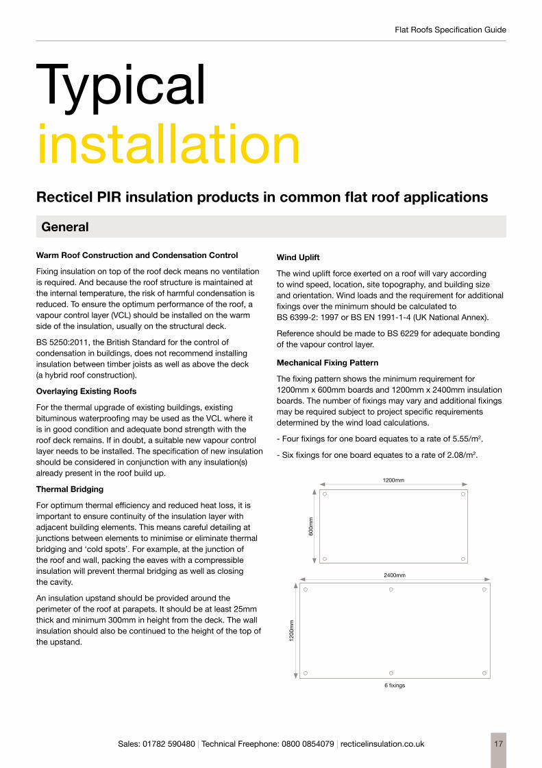
Mechanical Fixing Pattern
The fixing pattern shows the minimum requirement for 1200mm x 600mm boards and 1200mm x 2400mm insulation boards. The number of fixings may vary and additional fixings may be required subject to project specific requirements determined by the wind load calculations.
- Four fixings for one board equates to a rate of 5.55/m2.
- Six fixings for one board equates to a rate of 2.08/m2.
TypicalinstallationRecticel PIR insulation products in common flat roof applications
General
1200mm
600m
m
2400mm
6 fixings
1200
mm
18
Flat Roofs Specification Guide
Sales: 01782 590480 | Technical Freephone: 0800 0854079 | recticelinsulation.co.uk
Specifying Adhesives
PIR insulation is renowned for its chemical stability, although the foam core of boards can be softened if exposed to ketonic solvents. Non-ketonic polyurethane adhesives have no adverse effect on the foam; taping of board joints is not required when using polyurethane adhesives, as any excess adhesive running down between the board joints will not affect the exposed foam core. If in doubt, consult the adhesive manufacturer.
Roof Loading and Trafficking
Recticel Insulation’s flat roofing boards are suitable for loads associated with infrequent pedestrian maintenance traffic. Extra precautions should be taken in areas of heavier traffic, such as the use of walkways (consult membrane manufacturers for details). Take care to avoid damage to boards through impacts or concentrated loads.
When using ballasted and/or green roof systems, the roof structure must be designed to accept the additional dead load (minimum 80kg/m2).
Fire Performance
Recticel Insulation’s flat roofing boards will not prejudice the fire resistant properties of a roof and add no significant fire load to the building.
- Eurothane Eurodeck®: when tested in accordance with BS 476-3: 2004, the rating achieved by Eurothane Eurodeck® will vary depending on the single ply membrane used.
- Powerdeck® F: when tested to BS 476-3:2004, the product achieves an FAA rating when waterproofed with a 3-layer built-up felt covered with 10mm chippings. For other specifications it is advised to contact the manufacturer of the cap sheet for fire classification details. For single ply membranes the rating achieved will vary depending on the single ply membrane used.
- Powerdeck® U: when tested to ENV 1187:2002 Test 4, it achieves a BROOF (t4) rating on a plywood deck and with an IKO SBS Gold Seal cap sheet. For other specifications, contact the manufacturer of the waterproofing.
Roof Drainage
‘Ponding’ adds additional load to a roof, looks unsightly, and can shorten the lifespan of the roofing membrane. To ensure adequate drainage, any flat roof should have a minimum finished fall of 1:80. In reality, this means designing for twice the minimum fall to account for building inaccuracies, roof deflection and building settlement.
Tapered Systems
Recticel Insulation’s flat roofing boards are available as tapered systems. Tapered roofing insulation allows the necessary falls to be created where the roof structure does not. In refurbishment projects, it offers a simple solution to ponding issues at the same time as upgrading thermal performance.
Gradient UK, Recticel Insulation’s sister company, are experts in flat roofing and tapered insulation and can offer advice on the surveying, design and manufacture of bespoke single layer insulation solutions – from the earliest stages of a project through to its completion. For further details please contact: [email protected]
Flat Roofs Specification Guide
Sales: 01782 590480 | Technical Freephone: 0800 0854079 | recticelinsulation.co.uk 19
New Build
- Lay the specified VCL on the clean, dry deck. Ensure all laps are minimum 150mm and well-sealed, and turn up at the edge of the roof.
- If a fully-sealed metal deck is used, a separate VCL is not required.
- Mechanical fixing into a concrete deck may require pre-drilling of the deck.
- Install the Eurothane Eurodeck® boards in a tightly-butted brick bond pattern, mechanically fixing them using a minimum of 6 fixings per board (see ‘Wind Uplift’ and ‘Mechanical Fixing Pattern’).
- On a metal deck, the insulation boards should either be laid with the long edges at right angles to the troughs to ensure the short ends are fully supported, or diagonally across the deck corrugations.
- Thermally broken telescopic tube fixings are recommended to reduce thermal bridging, each incorporating a 50mm square or circular washer and positioned within 50 to 150mm of board edges and corners.
- If the desired insulation thickness comprises two layers, board joints should be staggered and the thicker layer positioned outermost. One or two fixings can be used to secure the lower boards, prior to securing the top layer with the required number of fixings.
- Lay and fix the single ply membrane in accordance with manufacturer’s instructions.
Refurbishment (Insulation Overlay)
- Where insulation is to be installed over existing waterproofing, it should be clean and dry and in appropriate condition to act as a VCL.
- If the condition of the existing waterproofing is poor, a separate VCL should be loose laid. Ensure all laps are minimum 150mm and well-sealed, and turn up at the edge of the roof.
- Install the Eurothane Eurodeck® boards in a tightly-butted brick bond pattern, mechanically fixing them using a minimum of 6 fixings per board (see ‘Wind Uplift’ and ‘Mechanical Fixing Pattern’).
- Thermally broken telescopic tube fixings are recommended to reduce thermal bridging, each incorporating a 50mm square or circular washer and positioned within 50 to 150mm of board edges and corners.
- If the desired insulation thickness comprises two layers, board joints should be staggered and the thicker layer positioned outermost. One or two fixings can be used to secure the lower boards, prior to securing the top layer with the required number of fixings.
- Lay and fix the single ply membrane in accordance with manufacturer’s instructions.
Mechanically Fixed Single Ply Membrane

20
Flat Roofs Specification Guide
Sales: 01782 590480 | Technical Freephone: 0800 0854079 | recticelinsulation.co.uk
New Build
- Install the VCL on the clean, dry deck. If a fully-sealed metal deck is used, a separate VCL is not required.
For bonded build-ups: bond a layer of coated roofing felt in hot bitumen, or with a proprietary adhesive. Where necessary, use a primer in accordance with manufacturer’s instructions to ensure an adequate bond between the deck and the VCL. On a timber deck, a layer of coated roofing felt can also be nailed.
For mechanically fixed build-ups: loose-lay the vapour control layer.
- Ensure all laps are minimum 150mm and well-sealed, and turn up at the edge of the roof.
- Install the Powerdeck® F boards in a tightly-butted brick bond pattern, with the long edges at right angles to the edge of the roof, or laid diagonally across the deck. On a metal deck, the long edges should be at right angles to the troughs to ensure the short ends are fully supported, or laid diagonally across the deck corrugations.
For bonded build-ups: apply a suitable proprietary adhesive to manufacturer’s instructions or mop hot bitumen over the VCL.
For mechanically fixed build-ups: thermally broken telescopic tube fixings are recommended to reduce thermal bridging, each incorporating a 50mm square or circular washer and positioned within 50 to 150mm of board edges and corners. Use a minimum of 4 fixings per board (see ‘Wind Uplift’ and ‘Mechanical Fixing Pattern’).
- If the desired insulation thickness comprises two layers, board joints should be staggered and the thicker layer positioned outermost. Where mechanically fixing, one or two fixings can be used to secure the first layer of boards, prior to securing the top layer with the required number of fixings.
- Install the chosen waterproofing in accordance with the manufacturer’s instructions and/or relevant British Standards.
Refurbishment (Insulation Overlay)
- Where insulation is to be installed over existing waterproofing, it should be clean and dry and in appropriate condition.
- If the condition of the existing waterproofing is poor or adequate bond strength cannot be guaranteed, a new or separate VCL should be installed.
For bonded build-ups: bond a layer of coated roofing felt in hot bitumen, or with a proprietary adhesive. Use a primer in accordance with manufacturer’s instructions to ensure an adequate bond between the existing roof and the VCL.
For mechanically fixed build-ups: loose-lay the vapour control layer.
- Ensure all laps are minimum 150mm and well-sealed, and turn up at the edge of the roof.
- Install the Powerdeck® F boards in a tightly-butted brick bond pattern, with the long edges at right angles to the edge of the roof, or laid diagonally across the deck.
For bonded build-ups: mop hot bitumen over the VCL, or apply a suitable proprietary adhesive to manufacturer’s instructions.
For mechanically fixed build-ups: thermally broken telescopic tube fixings are recommended to reduce thermal bridging, each incorporating a 50mm square or circular washer and positioned within 50 to 150mm of board edges and corners. Use a minimum of 4 fixings per board (see ‘Wind Uplift’ and ‘Mechanical Fixing Pattern’).
- If the desired insulation thickness comprises two layers, board joints should be staggered and the thicker layer positioned outermost. Where mechanically fixing, one or two fixings can be used to secure the first layer of boards, prior to securing the top layer with the required number of fixings.
- Install the chosen waterproofing in accordance with the manufacturer’s instructions and/or relevant British Standards.
Adhered Single Ply Membrane

Flat Roofs Specification Guide
Sales: 01782 590480 | Technical Freephone: 0800 0854079 | recticelinsulation.co.uk 21
New Build
- Install the VCL on the clean, dry deck. If a fully-sealed metal deck is used, a separate VCL is not required.
For bonded build-ups: bond a layer of coated roofing felt in hot bitumen, or with a proprietary adhesive. Where necessary, use a primer in accordance with manufacturer’s instructions to ensure an adequate bond between the deck and the VCL. On a timber deck, a layer of coated roofing felt can also be nailed.
For mechanically fixed build-ups: loose-lay the vapour control layer.
- Ensure all laps are minimum 150mm and well-sealed, and turn up at the edge of the roof.
- Install the Powerdeck® F boards in a tightly-butted brick bond pattern, with the long edges at right angles to the edge of the roof, or laid diagonally across the deck. On a metal deck, the long edges should be at right angles to the troughs to ensure the short ends are fully supported, or laid diagonally across the deck corrugations.
For bonded build-ups: mop hot bitumen over the VCL, or apply a suitable proprietary adhesive to manufacturer’s instructions.
For mechanically fixed build-ups: thermally broken telescopic tube fixings are recommended to reduce thermal bridging, each incorporating a 50mm square or circular washer and positioned within 50 to 150mm of board edges and corners. Use a minimum of 4 fixings per board (see ‘Wind Uplift’ and ‘Mechanical Fixing Pattern’).
- If the desired insulation thickness comprises two layers, board joints should be staggered and the thicker layer positioned outermost. Where mechanically fixing, one or two fixings can be used to secure the first layer of boards, prior to securing the top layer with the required number of fixings.
- Install the chosen waterproofing in accordance with the manufacturer’s instructions and/or relevant British Standards.
- Venting layers should be loose-laid on the insulation boards prior to bonding the first layer of felt.
Refurbishment (Insulation Overlay)
- Where insulation is to be installed over existing waterproofing, it should be clean and dry and in appropriate condition to act as a VCL.
- If the condition of the existing waterproofing is poor or adequate bond strength cannot be guaranteed, a new or separate VCL should be installed.
For bonded build-ups: bond a layer of coated roofing felt in hot bitumen, or with a proprietary adhesive. Use a primer in accordance with manufacturer’s instructions to ensure an adequate bond between the existing roof and the VCL.
For mechanically fixed build-ups: loose-lay the vapour control layer.
- Ensure all laps are minimum 150mm and well-sealed, and turn up at the edge of the roof.
- Install the Powerdeck® F boards in a tightly-butted brick bond pattern, with the long edges at right angles to the edge of the roof, or laid diagonally across the deck.
For bonded build-ups: mop hot bitumen over the VCL, or apply a suitable proprietary adhesive to manufacturer’s instructions.
For mechanically fixed build-ups: thermally broken telescopic tube fixings are recommended to reduce thermal bridging, each incorporating a 50mm square or circular washer and positioned within 50 to 150mm of board edges and corners. Use a minimum of 4 fixings per board (see ‘Wind Uplift’ and ‘Mechanical Fixing Pattern’).
- If the desired insulation thickness comprises two layers, board joints should be staggered and the thicker layer positioned outermost. Where mechanically fixing, one or two fixings can be used to secure the first layer of boards, prior to securing the top layer with the required number of fixings.
- Install the chosen waterproofing in accordance with the manufacturer’s instructions and/or relevant British Standards.
- Venting layers should be loose-laid on the insulation boards prior to bonding the first layer of felt.
Pour & Roll / Built-Up Felt

22
Flat Roofs Specification Guide
Sales: 01782 590480 | Technical Freephone: 0800 0854079 | recticelinsulation.co.uk
New Build
- Install the VCL on the clean, dry deck. If a fully-sealed metal deck is used, a separate VCL is not required.
For bonded build-ups: torch-apply or adhere a layer of coated roofing felt. Use a primer in accordance with manufacturer’s instructions to ensure an adequate bond between the deck and the VCL.
For mechanically fixed build-ups: loose-lay the vapour control layer.
- Mechanical fixing into a concrete deck may require pre-drilling of the deck.
- Ensure all laps are minimum 150mm and well-sealed, and turn up at the edge of the roof.
- Install the Powerdeck® U boards in a tightly-butted brick bond pattern, with the long edges at right angles to the edge of the roof, or laid diagonally across the deck. On a metal deck the long edges should be at right angles to the troughs to ensure the short ends are fully supported, or laid diagonally across the deck corrugations.
For bonded build-ups: mop hot bitumen over the VCL, or apply a suitable proprietary adhesive to manufacturer’s instructions.
For mechanically fixed build-ups: thermally broken telescopic tube fixings are recommended to reduce thermal bridging, each incorporating a 50mm square or circular washer and positioned within 50 to 150mm of board edges and corners. Use a minimum of 4 fixings per board (see ‘Wind Uplift’ and ‘Mechanical Fixing Pattern’).
- If the desired insulation thickness comprises two layers, board joints should be staggered and the thicker layer positioned outermost. Where mechanically fixing, one or two fixings can be used to secure the first layer of boards, prior to securing the top layer with the required number of fixings.
- Install the chosen waterproofing in accordance with the manufacturer’s instructions and/or relevant British Standards
Refurbishment(Insulation Overlay)
- Where insulation is to be installed over existing waterproofing, it should be clean and dry and in appropriate condition to act as a VCL.
- If the condition of the existing waterproofing is poor or adequate bond strength cannot be guaranteed, a new or separate VCL should be installed.
For bonded build-ups: torch-apply or adhere a layer of coated roofing felt. Use a primer in accordance with manufacturer’s instructions to ensure an adequate bond between the existing roof and the VCL.
For mechanically fixed build-ups: loose-lay the vapour control.
- Ensure all laps are minimum 150mm and well-sealed, and turn up at the edge of the roof.
- Install the Powerdeck® U boards in a tightly-butted brick bond pattern, with the long edges at right angles to the edge of the roof, or laid diagonally across the deck.
For bonded build-ups: mop hot bitumen over the VCL, or apply a suitable proprietary adhesive to manufacturer’s instructions.
For mechanically fixed build-ups: thermally broken telescopic tube fixings are recommended to reduce thermal bridging, each incorporating a 50mm square or circular washer and positioned within 50 to 150mm of board edges and corners. Use a minimum of 4 fixings per board (see ‘Wind Uplift’ and ‘Mechanical Fixing Pattern’).
- If the desired insulation thickness comprises two layers, board joints should be staggered and the thicker layer positioned outermost. Where mechanically fixing, one or two fixings can be used to secure the first layer of boards, prior to securing the top layer with the required number of fixings.
- Install the chosen waterproofing in accordance with the manufacturer’s instructions and/or relevant British Standards.
Torch-On Felt

Flat Roofs Specification Guide
Sales: 01782 590480 | Technical Freephone: 0800 0854079 | recticelinsulation.co.uk 23
New Build
- Install the VCL on the clean, dry deck. If a fully-sealed metal deck is used, a separate VCL is not required.
For bonded build-ups: bond a layer of coated roofing felt in hot bitumen, or with a proprietary adhesive. Where necessary, use a primer in accordance with manufacturer’s instructions to ensure an adequate bond between the deck and the VCL. On a timber deck, a layer of coated roofing felt can also be nailed.
For mechanically fixed build-ups: loose-lay the vapour control layer.
- Ensure all laps are minimum 150mm and well-sealed, and turn up at the edge of the roof.
Install the Powerdeck® F boards in a tightly-butted brick bond pattern, with the long edges at right angles to the edge of the roof, or laid diagonally across the deck. On a metal deck, the long edges should be at right angles to the troughs to ensure the short ends are fully supported, or laid diagonally across the deck corrugations.
For bonded build-ups: mop hot bitumen over the VCL, or apply a suitable proprietary adhesive to manufacturer’s instructions.
For mechanically fixed build-ups: thermally broken telescopic tube fixings are recommended to reduce thermal bridging, each incorporating a 50mm square or circular washer and positioned within 50 to 150mm of board edges and corners. Use a minimum of 4 fixings per board (see ‘Wind Uplift’ and ‘Mechanical Fixing Pattern’).
- If the desired insulation thickness comprises two layers, board joints should be staggered and the thicker layer positioned outermost. Where mechanically fixing, one or two fixings can be used to secure the first layer of boards, prior to securing the top layer with the required number of fixings.
- Install the chosen waterproofing in accordance with the manufacturer’s instructions and/or relevant British Standards.
Refurbishment (Insulation Overlay)
- Where insulation is to be installed over existing waterproofing, it should be clean and dry and in appropriate condition to act as a VCL.
- If the condition of the existing waterproofing is poor or adequate bond strength cannot be guaranteed, a new or separate VCL should be installed.
For bonded build-ups: torch-apply or adhere a layer of coated roofing felt. Use a primer in accordance with manufacturer’s instructions to ensure an adequate bond between the existing roof and the VCL.
For mechanically fixed build-ups: loose-lay the vapour control.
- Ensure all laps are minimum 150mm and well-sealed, and turn up at the edge of the roof.
- Install the Powerdeck® F boards in a tightly-butted brick bond pattern, with the long edges at right angles to the edge of the roof, or laid diagonally across the roof.
For bonded build-ups: mop hot bitumen over the VCL, or apply a suitable proprietary adhesive to manufacturer’s instructions.
For mechanically fixed build-ups: thermally broken telescopic tube fixings are recommended to reduce thermal bridging, each incorporating a 50mm square or circular washer and positioned within 50 to 150mm of board edges and corners. Use a minimum of 4 fixings per board (see ‘Wind Uplift’ and ‘Mechanical Fixing Pattern’).
- If the desired insulation thickness comprises two layers, board joints should be staggered and the thicker layer positioned outermost. Where mechanically fixing, one or two fixings can be used to secure the first layer of boards, prior to securing the top layer with the required number of fixings.
- Install the chosen waterproofing in accordance with the manufacturer’s instructions and/or relevant British Standards.
Mastic Asphalt

24
Flat Roofs Specification Guide
Sales: 01782 590480 | Technical Freephone: 0800 0854079 | recticelinsulation.co.uk
Warm Roof Construction and Condensation Control
Fixing insulation on top of the roof deck means no ventilation is required. And because the roof structure is maintained at the internal temperature, the risk of condensation is removed. A vapour control layer (VCL) should be provided on the warm side of the insulation, either in the form of mastic sealant or a minimum 1000g polythene sheet, depending whether the Plylok® is fixed directly to joists or on a roof deck.
This installation advice relates to fixing Plylok® boards directly to the top of joists. Where additional stability is desired, or where a polythene VCL is preferred, a minimum 18mm timber roof deck may be secured to the joists prior to fixing the Plylok® and installing the waterproofing.
BS 5250:2011, the British Standard for the control of condensation in buildings, does not recommend installing insulation between timber joists as well as above the deck (a hybrid roof construction).
Thermal Bridging
For optimum thermal efficiency and reduced heat loss, it is important to ensure continuity of the insulation layer with adjacent building elements. This means careful detailing at junctions between elements to minimise or eliminate thermal bridging and ‘cold spots’. For example, at the junction of the roof and wall, packing the eaves with a compressible insulation will prevent thermal bridging as well as closing the cavity.
An insulation upstand should be provided around the perimeter of the roof at parapets. It should be at least 25mm thick and minimum 300mm in height from the deck. The wall insulation should also be continued to the height of the top of the upstand.
Roof Loading and Trafficking
Plylok® boards are suitable for loads associated with infrequent pedestrian maintenance traffic. Extra precautions should be taken in areas of heavier traffic. Take care to avoid damage to boards through impacts or concentrated loads.
Fire Performance
Plylok® will not prejudice the fire resistant properties of the roof and adds no significant fire load to the building.
Drainage
‘Ponding’ adds additional load to a roof, looks unsightly, and can shorten the lifespan of the roofing membrane. To ensure adequate drainage, any flat roof should have a minimum
finished fall of 1:80. In reality, this means designing for twice the minimum fall to account for building inaccuracies, roof deflection and building settlement.
Installation Directly On Joists
- Lay Plylok® boards on 50mm wide joists with the plywood face up. The joists should be spaced at maximum 600mm centres, or 400mm centres where more frequent foot traffic is expected.
- Position the boards so the long edge of each board coincides with the centre of a joist, and install 50x50mm supporting noggins to support all other board edges, or where the insulation is cut to suit openings etc.
- All board edges require a minimum 20mm bearing onto the supporting timber.
- Apply water vapour resistant mastic sealant to all supporting joists and noggins prior to laying the insulation. This forms a continuous vapour control layer with the foil face of the boards.
- Secure the insulation boards with the chosen fixings. Appropriate fixings include: round-headed ring shank nails at 150mm centres along the line of each joist and noggin; oval-headed screw fixings at 200mm centres; or proprietary helical fixings at centres recommended by the manufacturer.
- Ensure the fixings penetrate the supporting timbers by at least 35mm and are positioned at least 10mm from board edges and 50mm from board corners. Where two boards are fixed on the same joist, stagger the fixings to each board.
- Finish nail and screw heads flush with the plywood surface. Do not over-drive fixings.
- The foil-faced underside of the Plylok® boards is not intended as a ceiling finish. Underline joists with a plasterboard ceiling or similar. If exposed joists are desired then plasterboard can be installed between, fixed to battens secured to the sides of the joists and just below the insulation.
- Waterproof the roof by the chosen method. Single ply membranes should be installed in accordance with the manufacturer’s instructions. Partially bonded built-up felt should be laid in accordance with BS 8217: 2005 and incorporate a 3G-type perforated base layer. Torch-on felt requires a torch-applied underlay to provide a vented layer where trapped vapour can disperse.
Typical Installation of Ply-faced Insulation Panels

Flat Roofs Specification Guide
Sales: 01782 590480 | Technical Freephone: 0800 0854079 | recticelinsulation.co.uk 25
General
Read these installation instructions carefully before installing Deck-VQ panels. Incorrect installation and/or the use of unsuitable tools can have undesirable effects on the characteristics of the panels or on the entire system.
If the panels show obvious visual defects, stop the installation and contact Recticel Insulation. Recticel Insulation accepts no liability for panels with obvious visual defects which have been installed anyway.
Safety
When handling and installing the panels, the appropriate safety measures must be set in place. It is the responsibility of the installer to make sure that site safety regulations are respected and personal protection equipment is available for and used by all people involved in the works.
Application
Deck-VQ is used as thermal insulation for terraces and flat roofs that are subject to light foot traffic. If higher loads or frequent foot traffic (e.g. regular maintenance) is to be expected, adequate protection must be foreseen.
Storage and protection
To protect and optimise the premium thermal performance the panels must be handled with care. Please take into account the following guidelines:
- Deck-VQ panels must be stored in a sheltered location or completely covered (e.g. by a plastic cover) in a dry, well-ventilated area. We advise a minimum distance of 100 mm between ground level and the lowest panel. If there are indications that this distance is not sufficient, take appropriate measures.
- The pallets (ca. 1200 mm x 1200 mm) should be supported by at least three supporting blocks. The pallets can be stacked one on top of the other, but for safety reasons we recommend to limit the stack height to two pallets.
- The packaging must remain intact until the time of installation. The packaging itself is not considered to be a sufficiently protective or watertight covering.
- Do not store any flammable objects on or next to the panels. It is also forbidden to store the panels next to a heat source (for example radiators, heaters, a naked flame etc.).
- No (sharp) objects can be placed on top of the insulation boards in order to avoid damage.
- The insulation boards have to be kept dry at all times! This applies to both storage and installation of the boards. At the end of the working day or when the works have to be stopped, the installed boards have to be covered and protected from rain, snow and ice (e.g. by applying a temporary waterproofing membrane).
- Damaged boards cannot be used in the roof build-up.
Mounting and fixing1
Vacuum insulation panels are to be treated with care. The innovative concept of Deck-VQ entails the VIP inside to be protected by a high density PIR insulation board on all sides to avoid incidental damage.
General considerations
1. The insulation boards are applied on a new vapor control layer (VCL)2 or an existing waterproofing membrane on top of concrete, wood and metal decks. The waterproofing is realized with ballasted or adhered waterproofing systems.
2. The substrate has to be flat, dry (no water, no ice, no snow) and free of waste and dust. In case of renovations, always check the condition of the existing waterproofing membrane.
3. Deck-VQ panels should not be cut or punctured, as this will compromise the thermal performance. Also, obstacles on the roof or terrace should be considered in an early stage to insure a correct installation. Therefore the following guidelines are to be taken into account:
a. Use a layout scheme to ensure an optimal panel configuration. The configuration should take into account the location of the different obstacles and roof/terrace details, e.g. gutters, drains, roof lights, chimneys… This service is offered by the Technical department of Recticel Insulation upon request.
Typical Installation of Vacuum Insulation Panels
An example of a layout scheme indicating the different panel types and the infill area (shaded area)

26
Flat Roofs Specification Guide
Sales: 01782 590480 | Technical Freephone: 0800 0854079 | recticelinsulation.co.uk
1 The client must ensure that the mounting of the boards, and by extension the complete flat roof build-up, is in conformity with all laws, regulations, directives and national/international demands which are applicable. The installation has to be done according to code of good practice.
2 A U-value calculation and condensation risk analysis (CRA) are recommended to determine a correct build-up and the minimum quality of VCL to be applied. Recticel Insulation provides this service upon request, please contact the Technical department for more information.
b. The Deck-VQ concept incorporates ‘infill’ PIR boards that can be adjusted to fit construction details and to obtain a complete coverage of the surface to be insulated. Powerdeck F boards are used as infill because the facer offers a compatibility with adhesives which is similar to the facer of the protective high density PIR boards that encapsulate the VIP.
c. If additional mechanical fixings are necessary in highly solicited areas around the perimeter of the roof (e.g. after a wind uplift calculation), this information must be communicated clearly. As the Deck-VQ panels are not to be punctured, the panel configuration in the layout scheme will have to account for additional infill areas which allow mechanical fixing of the waterproofing membrane.
d. The same applies for structures that need to be mechanically fixed to the substrate, through the insulation layer (e.g. fixed fall protection). If known beforehand, designated areas can be foreseen in the layout scheme. Recticel Insulation cannot be held accountable for not including these areas in the scheme if not clearly communicated by the requestor (customer/installer).
e. Please note that existing roofs might require wider infill areas around the perimeter of the roof to take into account the sloped roof finishing towards the roof edge.
4. The insulation boards are placed in a continuous, tight fitting way (without any gaps) in order to avoid thermal bridges and thus to create a continuous insulation shield.
5. Single and multi-layered insulation build-ups can be applied, always respecting the staggered pattern within and between layers. Every subsequent layer has to be staggered referring to the previous layer.
a. Ideally the joints are staggered by half a board
b. If not possible, the boards should be staggered for at least 200 mm
6. Remark: The VCL has to be put up at e.g. roof upstands, in order to make a connection with the waterproofing layer, creating a complete and closed envelope around the insulation boards.
7. To provide adequate water drainage, the roof/terrace build up must incorporate a fall towards gutters and outlets. To achieve this, either the substrate must provide the fall, or Deck-VQ can be combined with the tapered insulation solutions of Recticel Insulation. For more information on our tapered solutions, please see our website or contact Recticel Insulation
Installation of the flat roof system
In what follows, it is assumed that a VCL has been installed correctly and is suitable for installation of the other components of the flat roof system.
Adhered application
General
The gluing in a flat roof system build-up is two-fold:- Gluing of the insulation boards to the substrate (i.e.
supporting deck, VCL, existing roof covering, other insulation boards).
- Gluing of the waterproofing membrane to the insulation board (see “Gluing – waterproofing membrane to insulation”).
Following types of glue are usually compatible with the Deck-VQ insulation boards:- PU-glue (1 component moisture-cured, 2 components),
liquid or foam- Bituminous cold glueRemarks :1. Compatibility of the glue with the insulation boards has to
be confirmed by the manufacturer of the glue and/or Recticel Insulation. In case of doubt, please contact the technical service team of Recticel Insulation at [email protected].
2. Solvent based glues which might damage the facer or the foam of the insulation boards, cannot be used!
3. The glue has to be compatible with the substrate and/or waterproofing membrane as well. In case of renovation, always check the condition of the existing waterproofing membrane which will be covered. Make sure this is a substrate which allows for adhered applications.
4. In case of unevenness in the substrate (e.g. old bituminous waterproofing membrane with thick overlaps) it’s recommended to use a foaming type of glue to level out these imperfections.
- The installation instructions of the glue manufacturer are to be respected at all times! This concerns the required amount of glue, glue pattern, the minimal application temperature, storage temperature, opening time, curing time, etc.
- Gluing of boards is anyhow not allowed in case of cold temperatures (< 5°C) or in case of humid substrates.
- It’s not allowed to walk over the boards immediately after they are glued to the deck. The instructions of the manufacturer need to be respected.
Flat Roofs Specification Guide
Sales: 01782 590480 | Technical Freephone: 0800 0854079 | recticelinsulation.co.uk 27
Gluing - Insulation to deck
- The glue needs to be applied according to the glue manufacturer’s instructions. PU-glues are applied in an S-shape pattern or in straight lines.
- Bituminous cold glues can be applied by means of dabs or straight lines as shown in the drawing below. In case of dabs, make sure that for a 1200 x 600 mm and 1200 x 300 mm board there are at least 5 sufficiently large dabs, spread over the insulation board (1 in each corner + 1 in the middle of the board). For the 600 x 600 and 600 x 300 mm boards, four dabs can be sufficient. Always respect the coverage prescribed by the manufacturer of the adhesive.
- Glue needs to be foreseen in such a way that all edge- and corner zones of the insulation boards are covered. Do not only put glue in the middle of the boards!
- The amount of glue and the corresponding glue pattern is prescribed by the manufacturer of the glue. The amount and pattern need to be densified in the parts of the roof where the wind load is increased (e.g. edges and corners). In case the wind load is too high, additional mechanical fixings or ballast can be required. This information has to be communicated clearly, so it can be taken into account in the layout scheme (see “General considerations”).
- In case of multi-layered build-ups, all layers need to be sufficiently adhered to the substrate/underlying insulation layer, as if these layers would be the only layers in the build-up.
Gluing – waterproofing membrane to insulation
The gluing in a flat roof system build-up is two-fold:- Recticel Insulation recommends partially adhered single-ply
membranes (cold adhered or self-adhesive) or multi-ply systems (partially self-adhesive base sheet and torch-on cap sheet).
- Fully self-adhesive membranes are not allowed in combination with Deck-VQ.
Remarks :1. The instructions of the waterproofing membrane producer
need to be followed and the glue needs to be compatible with both the insulation board and the waterproofing membrane.
2. When solvent based glues are used, make sure the solvents are evaporated sufficiently before the waterproofing membrane is folded onto the insulation boards.
3. In case of non-fleece backed / naked synthetic membranes, Recticel recommends to only apply them partially adhered to the insulation board to avoid blistering. Fleece backed synthetic membranes can also be used as the fleece is considered as a vapor diffusion layer.
Torch-on waterproofing membranes
Installation of the insulation
The Deck-VQ boards are installed according to the guidelines in “Adhered application”
Installation of the waterproofing membrane
Bituminous waterproofing membranes cannot be torched directly onto the Deck-VQ panels, a (self-adhesive) base sheet has to be applied before applying the torch-on cap sheet.
- The first layer which is applied to the board has to be partially adhered (allowing vapor pressure diffusion). The second layer can be fully torched onto this first layer.
- Never point the tip of the torch directly to the insulation boards, but always point it to the roll of waterproofing membrane!
- Torching is not allowed on insulation boards which are fixed to the substrate by means of bituminous cold glue due to the extended curing time of the glue.
Ballasted application
Deck-VQ boards can be loosely laid in a ballasted flat roof system. Please note that the installation of the insulation, the waterproofing membrane and the ballast have to follow each other quickly to ensure a good performance.
Installation of the insulation
Please take into account the guidelines under “General considerations”.
Installation of the waterproofing membrane
The waterproofing membrane must be applied according to the instructions from the supplier/manufacturer. Please refer to the documentation of the supplier for more information and make sure the waterproofing membrane is suitable for ballasted application.
Ballast The total characteristics (e.g. type, weight, diameter…) of the ballast have to be in accordance with the required wind uplift resistance and needs to be applied as soon as possible after installation of the waterproofing membrane.
Generally we distinguish the following two types of ballast to be applied on Deck-VQ:
- Gravel: depending on the type of gravel it can be necessary to apply a protective layer between the waterproofing membrane and the gravel to avoid damaging the waterproofing membrane.
- Tiles: when combined with tile supports (spacers), the minimum support area on top of the waterproofing membrane needs be larger than 100 cm². For heavy loads, please contact our Technical Department for assistance.

28
Flat Roofs Specification Guide
Sales: 01782 590480 | Technical Freephone: 0800 0854079 | recticelinsulation.co.uk
100
Single Layer Tapered Roof Systems
Typical Multi-Layer
Gradient Bonded Single-Layer
Example shown is Powerdeck F.
Simplified Projects Single-layer system, pre-cut and factory bonded for easy installation
Perfect fit Factory fabricated to ensure precise tolerances are met
Quick installation Pre-cut, accurate components allow for speedy installation
2040
6080
120140
160180
200220
240260
280300
320340
360380
400 420
A B C D E F G H I J K L M N O P Q R S T
2040
6080
100120
140160
180200
220240
260280
300320
340360
380400 420
A B C D E F G H I J K L M N O P Q R S T
100mm Flat Board
100mm Flat Board
100mm Flat BoardA B
CD
EA B
CD
EA B
CD
EA B
CD
E
Most cost effective flat roof solution
£
£
Optimum adhesion Factory bonded to provide reliable adhesion and integrity
Reduced maintenance Consistent, reliable performance over the life of the roof
Less waste Single-layer boards are delivered at the right size, reducing cutting on-site
gradientuk.com01543 678777 | [email protected]

Flat Roofs Specification Guide
Sales: 01782 590480 | Technical Freephone: 0800 0854079 | recticelinsulation.co.uk 29
EnglandPART L 2013
U-values are part of wider assessment criteria to meet the requirements of Part L as a whole. Other factors taken into account include: airtightness, door and window U-values, the heating system, and thermal bridging.
‘Limiting U-values’ are the worst acceptable level of performance, but designing to these values is unlikely to result in compliance. The ‘notional building specification’ is a recipe approach that will ensure compliance if all standards are met. Regulatory compliance should be assessed through the appropriate SAP (for domestic) or SBEM (for non-domestic) calculation software.
NEW BUILD: L1A – new dwellings; L2A – new buildings other than dwellings
Floor External Wall
Flat Roof
Pitched Roof
Sloped Ceiling
Flat Ceiling
L1A
Notional dwelling 0.13 0.18 0.13 0.13 0.13
Limiting Values 0.25 0.30 0.20 0.20 0.20
L2A
Notional building 0.22 0.26 0.18 0.18 0.18
Limiting Values 0.25 0.35 0.25 0.25 0.25
EXISTING PROPERTIES: L1B – existing dwellings; L2B – existing buildings other than dwellingsU-value requirements for existing buildings are unchanged from Part L 2010.
Floor External Wall
Flat Roof
Pitched Roof
Sloped Ceiling
Flat Ceiling
L1B & L2B
New element 0.22 0.28 0.18 0.18 0.16
Retained element 0.25 0.30* 0.18 0.18 0.16
*where insulation is installed internally or externally
WalesPART L 2014
U-values are part of wider assessment criteria to meet the requirements of Part L as a whole. Other factors taken into account include: airtightness, door and window U-values, the heating system, and thermal bridging.
‘Limiting U-values’ are the worst acceptable level of performance, but designing to these values is unlikely to result in compliance. The ‘notional building specification’ is a recipe approach that will ensure compliance if all standards are met. Regulatory compliance should be assessed through the appropriate SAP (for domestic) or SBEM (for non-domestic) calculation software.
NEW BUILD: L1A – new dwellings; L2A – new buildings other than dwellings
Floor External Wall
Flat Roof
Pitched Roof
Sloped Ceiling
Flat Ceiling
L1A
Notional dwelling 0.15 0.18 0.11 0.11 0.11
Limiting Values 0.18 0.21 0.15 0.15 0.15
L2A Notional building 0.22 0.26 0.18 0.18 0.18
EXISTING PROPERTIES: L1B – existing dwellings; L2B – existing buildings other than dwellings
Floor External Wall
Flat Roof
Pitched Roof
Sloped Ceiling
Flat Ceiling
L1B
New element 0.18 0.21 0.15 0.15 0.15
Retained element 0.25 0.30 0.18 0.18 0.16
L2B - all elements
Domestic* 0.18 0.21 0.15 0.15 0.15
Limiting Values 0.22 0.26 0.18 0.18 0.15
*refers to buildings other than dwellings that are ‘domestic’ in character
Buildingregulations
(the values are presented in W/m²K). (the values are presented in W/m²K).
(The values are presented in W/m²K).
(The values are presented in W/m²K).

30
Flat Roofs Specification Guide
Sales: 01782 590480 | Technical Freephone: 0800 0854079 | recticelinsulation.co.uk
ScotlandSECTION 6 2015
U-values are part of wider assessment criteria to meet the requirements of Section 6 as a whole. The ‘notional building specification’ is a recipe approach that will ensure compliance if all standards are met. Regulatory compliance should be assessed through the appropriate SAP (for domestic) or SBEM (for non-domestic) calculation software.
DOMESTIC NEW BUILD
As well as U-values, the notional dwelling specifications for gas, LPG and oil fuel packages take into account: airtightness, door and window U-values, the heating system, and thermal bridging. They also include photovoltaics and waste water heat recovery. Specifying U-values therefore needs to be done in careful consideration with the entire dwelling package.
Floor External Wall
Flat Roof
Pitched Roof
Sloped Ceiling
Flat Ceiling
New domestic (notional dwelling) 0.15 0.17 0.11 0.11 0.11
Existing Domestic Properties
For extensions to existing dwellings, the required U-values for the new elements depend on the performance of the existing building:
The higher standards in ‘A’ apply where the walls of the existing building have a U-value poorer than 0.70 and the roof is poorer than 0.25.
‘B’ applies where the walls of the existing building have a U-value better than 0.70 and the roof better than 0.25, or will be upgraded to those levels as part of the works.
Where existing domestic elements are to be altered or refurbished, the standards in ‘B’ apply.
Floor External Wall
Flat Roof
Pitched Roof
Sloped Ceiling
Flat Ceiling
Existing domestic
A 0.15 0.17 0.13 0.13 0.11
B 0.18 0.22 0.18 0.18 0.15
NON-DOMESTIC BUILDINGS – NEWAND EXISTING
For all building types, early consultation with Local Authority Building Standards is advised.
Non-domestic new build standards are based on heating/ventilation specification (natural or mechanical) and have different limiting values depending on type of building (e.g. shell construction where future occupancy/use is uncertain).
For existing buildings, a degree of flexibility is available depending on the feasibility of achieving U-value targets (e.g. in listed buildings). Again, early discussion Local Authority Building Standards is recommended.
(The values are presented in W/m²K).
(The values are presented in W/m²K).

Flat Roofs Specification Guide
Sales: 01782 590480 | Technical Freephone: 0800 0854079 | recticelinsulation.co.uk 31
The sustainablesolution
Minimising our CO2 footprint
We make constant efforts to minimise our CO2 footprint by reducing the negative impact of our operations while significantly increasing the positive impact of our products. We estimate that the CO2 emissions prevented by our insulation solutions in 2017 totalled over 30 times our carbon impact throughout the value chain.
We also try to reduce energy use in our factories. Most of our production plants are certified to ISO 14001 standards of environmental care.
When developing or launching new production plants, we choose green energy sources where possible in order to reduce our CO2 footprint.
Recticel Insulation products offer significant environmental benefits. Efficient insulation means that less energy is needed for heating and cooling. As a result, CO2 emissions are reduced, which means that our insulation products contribute significantly to the fight against global warming.
The durability of our products is another important environmental advantage. Polyurethane insulation boards have a 50-year lifespan. Their insulation performance remains consistent throughout the lifetime of the product, making them a very sustainable solution. In addition, our manufacturing facility operates to an ISO 14001 certified Environmental Management System.
The Recticel Group’s sustainability strategy was developed to respond to key challenges such as energy conservation, CO2 reduction, and an aging and increasing population. Sustainability is also deeply embedded in the Group’s DNA. This is evident in the company’s core values, one of which is “We act with respect and integrity”. Recticel Insulation adheres to this value by showing respect for all of society, particularly our employees, partners, the planet and legislation. We expect our core values to be applied not just by our colleagues, but also by our partners.
32
Flat Roofs Specification Guide
Sales: 01782 590480 | Technical Freephone: 0800 0854079 | recticelinsulation.co.uk
Waste management and recycling
We seek out new ways to avoid waste during the production process, as well as possibilities to reuse or recycle production waste and products that have reached the End-Of-Life (EOL) phase. We also try to minimise the use of finite natural resources.
The BRE Green Guide
The 2008 Green Guide to Specification produced by the BRE gives Recticel Insulation products manufactured in the UK a summary rating of A.
Green Guide ratings are used to gain credits in BREEAM (BRE Environmental Assessment Method) for non-residential buildings, and under ‘Mat 4 – Insulation’ the first credit requires the building to have an Insulation Index of 2 or greater – only achievable if the weighted average rating of the insulation is A or A+.
Responsible Sourcing
The second BREEAM credit under that category is based on responsibly-sourced materials – at least 80% of the total insulation used in roofs, walls, ground floors and services must meet any of tier levels 1 to 6 in the BREEAM table of certification schemes.
Our Environmental Management System is certified under BS EN ISO 14001, and our raw materials come from companies with similarly-certified EMS (copies of all certificates are available for BREEAM assessments). This level of responsible sourcing meets tier level 6 in the BREEAM table.
Global Warming and Ozone Depletion
All Recticel Insulation products use CFC-and HCFC-free materials, and are manufactured using a blowing agent with a low GWP and zero ODP.
BREEAM
The Building Research Establishment’s Environmental Assessment Method is an internationally-recognised process for assessing any type of building, of any age, anywhere in the world against established environmental and sustainability benchmarks. Although heat loss and energy use have a significant influence on the calculation method, environmental performance is measured by awarding credits in a number of categories, each of which is given a different weighting.

Flat Roofs Specification Guide
Sales: 01782 590480 | Technical Freephone: 0800 0854079 | recticelinsulation.co.uk 33
Technical support
Fabric First
Concentrate on getting a building’s fabric right and each element - whether a floor, wall or roof - will be well-built, thermally efficient and airtight, achieving the designed level of performance for the life of the building. At Recticel, we advocate ‘fabric first’ as the best way to reduce energy consumption.
Sharing aspects of the Passivhaus comfort standard, a fabric first approach concentrates on high levels of thermal performance and airtightness (including from doors and windows), and reduced thermal bridging. Air quality is also a vital part of the building specification to ensure occupant comfort and health, so the correct ventilation strategy needs to be considered - possibly requiring mechanical ventilation with heat recovery (MVHR). When it comes to the insulation specification, we’ll recommend the right thickness of PIR to meet your requirements in the most efficient manner possible.
The Performance Gap
While new buildings might meet thermal regulations on paper, the actual performance level once occupied can be well below expectations. Although we can advise on the theoretical performance of our products in particular building elements, we still rely on contractors and site supervisors to make sure they perform as intended – so we’re committed to providing more information and improving knowledge about the installation of our products.
Thermal Bridging Models
Linear thermal transmittance (or psi value) is a measure of heat loss at junctions. In order to minimise this, it is necessary to ensure continuity of the insulation layer across adjacent building elements. This means careful detailing of junctions between elements and openings to reduce thermal bridging. For example; between wall and roof, wall and floor, lintel and wall.
Why is it important to consider thermal bridging details?
Recent changes to building regulations have resulted in lower U-value requirements for the main construction elements. As thermal transmittance through these elements reduces, heat energy seeks to escape by the path of least resistance, normally through inadequately insulated junctions. Heat loss at junctions can account for up to 15% of a building’s total heat loss.
Accredited and Enhanced Construction Details (ACDs & ECDs) are one way of limiting heat loss through thermal bridging at junctions, reducing psi values and improving the overall fabric energy efficiency of the building. An additional benefit of minimising thermal bridging is reducing the risk of surface condensation and associated mildew at otherwise cold spots, and thereby improving occupant health.
Recticel Insulation’s range of thermal bridging details can assist designers with improved psi values for use in SAP calculations to ensure that carbon emissions and fabric energy efficiency targets of the latest building regulations are achieved, or even exceeded.
To help you find the best insulation products for your project – and comply with building regulations – our dedicated technical team can provide you with U-value calculations, condensation risk analysis and advice on installation.
Our team is focused on helping specifiers in particular specialist areas, details of which can be found at recticelinsulation.co.uk

34
Flat Roofs Specification Guide
Sales: 01782 590480 | Technical Freephone: 0800 0854079 | recticelinsulation.co.uk
U-values
Recticel Insulation supports the accurate calculation of U-values for the construction industry. Calculations are issued under the Competent Person scheme administered by the BBA (British Board of Agrément). All U-values are calculated by the Combined Method, in accordance with the conventions detailed in BS EN ISO 6946, BR 443, and other standards laid out by the BBA in their scheme guidance.
Calculations are provided free of charge to demonstrate the performance of Recticel products and compliance with building regulations. Calculation requests can be emailed to [email protected].
Recticel U-value calculations can be supplied with a Condensation Risk Analysis where appropriate, and additional guidance is offered when required. Advice on condensation risk is given in accordance with BS EN ISO 13788 and BS 5250.
BIM (Building Information Modelling)
BIM not only helps with building simulation and architectural data, but also with structural engineering, sustainability and even project and cost management. To support architects and specifiers who use the BIM framework, we’ve utilised our relationship with RIBA through the NBS Product Selector and made our products available as ‘BIM Objects’ held within the NBS National BIM Library.
For instant access to Recticel’s BIM library visit:www.bimstore.co/manufacturers/recticel-insulation-products
Single Layer Tapered Roofing Systems
Gradient work closely with customers and specifiers to design, manufacture and advise on the installation of bespoke, single-layer tapered roofing solutions.
It’s a turnkey service that provides everything from initial consultation and design to after sales support. By controlling the whole process from start to finish, we are able to exercise control standards for design, manufacture, performance and sustainability that are unmatched in the industry. Benefits we pass on to you in the form of a better conceived, better performing, better value flat roof that complies with all the relevant legislative standards
For more information visit: www.gradientuk.com or call one of our technical support specialists on 01543 678777.
NBS Plus
RIBA NBS Plus gives architects access to a library of product information that can be consulted or copied directly into building specifications, supported by the RIBA Product Selector building product directory, both of which are widely used by industry professionals. Recticel products are listed within the RIBA product selector, making them accessible to all specifiers instantly.
Certification
All our products are manufactured to the harmonised European standard EN 13165, and are CE marked accordingly. Where stated, products have been certified by the British Board of Agrément (BBA). Our manufacturing facilty operates to an ISO 9001 Quality System and ISO 14001 Environmental Management System. Declarations of Performance are available as required by the Construction Product Regulations.
CPD Presentations
Recticel Insulation is a member of the RIBA CPD Providers Network, which features manufacturers and suppliers who provide RIBA Continuing Professional Development to architects and specifiers.
We offer a range of RIBA CPD Assessed Material (some of which is part of the RIBA CPD Core Curriculum), including seminars (typically 45 minutes in duration, with 15 minutes available for questions and answers after) and CPD Articles that can be accessed directly on the RIBA CPD website.
Seminar bookings are available across the UK and can be requested online, via either the Recticel Insulation or RIBA CPD websites.

Flat Roofs Specification Guide
Sales: 01782 590480 | Technical Freephone: 0800 0854079 | recticelinsulation.co.uk 35
ProductcharacteristicsDurability
Treated with appropriate care and installed correctly, Recticel Insulation products have a 50-year lifespan and should not require maintenance. They are resistant to mould growth and will not rot.
PIR foam is not resistant to solvent-based products and should not be used in conjunction with them. Any boards that have come into contact with solvents or acids, or been damaged by such products, should be discarded.
PIR foam is a closed cell material, meaning water absorption is minimal. However, they should always be protected from the elements and never installed in exposed situations such as inverted flat roofs or in direct contact with the ground. Boards should be kept dry during installation and covered at the end of each day’s work on site. If boards get wet, they should be allowed to dry naturally and checked for damage prior to use. If in doubt please contact Technical Services for further advice.
Handling, Cutting and Storage
Recticel Insulation’s PIR boards are lightweight and inherently safe to handle. They should be treated with respect and maintained in the best possible condition during installation to ensure they perform as expected over the life of the building. They can be cut with a sharp knife or fine toothed saw.
Boards are supplied in polythene shrink wrap which is designed for short-term protection only. It is accepted that storing boards indoors is not always possible – when outdoor storage is necessary, boards should be stored clear of the ground, on a level surface, and under cover to protect them from prolonged exposure to moisture or mechanical damage.
Recticel Insulation products should not be installed when the temperature is at or below 5°C and falling.
Health and Safety
A comprehensive Product Information Data Sheet (PIDS) is available on request.
During cutting or machining, any dust is of nuisance value only. Large scale machining should be connected to a dust extraction system.
Foil-faced boards reflect light as well as heat, including ultraviolet light. Installation during bright weather may require UV eye protection, and a high SPF sun cream for bare skin. Foil facings can also become slippery when wet.
Avoid skin and eye contact with any sharp edges. Do not stand on or otherwise support your weight on boards unless the product is fully supported by a load-bearing surface.
Using Recticel PIR Insulation
Recticel InsulationEnterprise WayWhittle Road
Meir ParkStoke-on-Trent
ST3 7UN
Technical freephone: 0800 0854079
Technical support email: [email protected]
Customer support email: [email protected]
t: 01782 590470f: 01782 590497
www.recticelinsulation.co.ukrecticelinsulation.co.uk
Issue date: September 2020
Care has been taken to ensure that the content of this document is as accurate as possible.Please note that technical specifications may vary from country to country. Recticel Insulation
does not accept any liability for clerical errors and reserves the right to amend informationwithout prior notice. This document does not create, specify, modify or replace any
new or prior contractual obligations agreed upon in writing betweenRecticel Insulation and the user.
BRO009042301-FRB-08/2020
@RecticelInsulUKRecticel Insulation UK