TWO MARK QUESTIONS EE6301 DIGITAL LOGIC … MARK QUESTIONS EE6301 DIGITAL LOGIC CIRCUITS UNIT I...
28
ENSOLT Elakkia notes TWO MARK QUESTIONS EE6301 DIGITAL LOGIC CIRCUITS UNIT I NUMBER SYSTEMS AND DIGITAL LOGIC FAMILIES Review of number systems, binary codes, error detection and correction codes (Parity and Hamming code0- Digital Logic Families ,comparison of RTL, DTL, TTL, ECL and MOS families -operation, characteristics of digital logic family. UNIT II COMBINATIONAL CIRCUITS Combinational logic - representation of logic functions-SOP and POS forms, K-map representations minimization using K maps - simplification and implementation of combinational logic – multiplexers and demultiplexers - code converters, adders, subtractors. UNIT III SYNCHRONOUS SEQUENTIAL CIRCUITS Sequential logic- SR, JK, D and T flip flops - level triggering and edge triggering - counters - asynchronous and synchronous type - Modulo counters - Shift registers - design of synchronous sequential circuits – Moore and Melay models- Counters, state diagram; state reduction; state assignment. UNIT IV ASYNCHRONOUS SEQUENTIAL CIRCUITS AND PROGRAMMABLE LOGIC DEVICES Asynchronous sequential logic circuits-Transition table, flow table-race conditions, hazards &errors in digital circuits; analysis of asynchronous sequential logic circuits-introduction to Programmable Logic Devices: PROM – PLA –PAL. UNIT V VHDL RTL Design – combinational logic – Sequential circuit – Operators – Introduction to Packages – Subprograms – Test bench. (Simulation /Tutorial Examples: adders, counters, flipflops, FSM, Multiplexers /Demultiplexers). TEXT BOOKS: 1. Raj Kamal, ‘ Digital systems-Principles and Design’, Pearson Education 2nd edition, 2007. 2. M. Morris Mano, ‘Digital Design with an introduction to the VHDL’, Pearson Education, 2013. 3. Comer “Digital Logic & State Machine Design, Oxford, 2012.
Transcript of TWO MARK QUESTIONS EE6301 DIGITAL LOGIC … MARK QUESTIONS EE6301 DIGITAL LOGIC CIRCUITS UNIT I...

ENSOLT Elakkia notes
TWO MARK QUESTIONS
EE6301 DIGITAL LOGIC CIRCUITS
UNIT I NUMBER SYSTEMS AND DIGITAL LOGIC FAMILIES
Review of number systems, binary codes, error detection and correction codes (Parity and Hamming
code0- Digital Logic Families ,comparison of RTL, DTL, TTL, ECL and MOS families -operation,
characteristics of digital logic family.
UNIT II COMBINATIONAL CIRCUITS
Combinational logic - representation of logic functions-SOP and POS forms, K-map representations
minimization using K maps - simplification and implementation of combinational logic – multiplexers and
demultiplexers - code converters, adders, subtractors.
UNIT III SYNCHRONOUS SEQUENTIAL CIRCUITS
Sequential logic- SR, JK, D and T flip flops - level triggering and edge triggering - counters - asynchronous
and synchronous type - Modulo counters - Shift registers - design of synchronous sequential circuits –
Moore and Melay models- Counters, state diagram; state reduction; state assignment.
UNIT IV ASYNCHRONOUS SEQUENTIAL CIRCUITS AND PROGRAMMABLE LOGIC DEVICES
Asynchronous sequential logic circuits-Transition table, flow table-race conditions, hazards &errors in
digital circuits; analysis of asynchronous sequential logic circuits-introduction to Programmable Logic
Devices: PROM – PLA –PAL.
UNIT V VHDL
RTL Design – combinational logic – Sequential circuit – Operators – Introduction to Packages –
Subprograms – Test bench. (Simulation /Tutorial Examples: adders, counters, flipflops, FSM, Multiplexers
/Demultiplexers).
TEXT BOOKS: 1. Raj Kamal, ‘ Digital systems-Principles and Design’, Pearson Education 2nd edition, 2007. 2. M. Morris Mano, ‘Digital Design with an introduction to the VHDL’, Pearson Education, 2013. 3. Comer “Digital Logic & State Machine Design, Oxford, 2012.

ENSOLT Elakkia notes
Q A Prepared by ENSOLT Elakkia
UNIT-I NUMBER SYSTEMS AND DIGITAL LOGIC FAMILIES
1. Where the digital systems are used?
Digital systems are used extensively in computation and data processing, control systems,
Communications and measurements. Since digital systems are capable of greater accuracy and
reliability than analog systems, many tasks formerly done by analog are now being performed
digitally.
2. What is the difference between analog and digital systems?
In a digital system the physical quantities or signals can assume only discrete values, while in
analog systems the physical quantities or signals vary continuously over a specified range.
3. What is a binary number system and Why are binary numbers used in digital systems?
The number system with base (or radix) two is known as the binary number system. Only two
symbols are used to represent the numbers in the system and these are 0 and 1.The outputs of
the switching devices used in digital systems assume only two different values. Hence it is natural
to use binary numbers internally in digital systems.
4. What is the difference between binary code and BCD?
Binary: Any distinct element can be represented by a binary code.
No limitation for the minimum or maximum number of elements required for coding
the element.
BCD: Only a decimal digit can be represented.
It is a four bit representation.
5. What is an Excess3 code?
The excess3 code is a non weighted code which is obtained from the 8-4-2-1 code by adding
3(0011) to each of the codes.
6. What is a gray code and mention its advantages.
A gray code is a non weighted code which has the property that the codes for successive decimal
digits differ in exactly one bit.
The gray code is used in applications where the normal sequence of binary numbers may produce
an error during the transition from one number to the next.
7. What is meant by non-weighted codes?
Each bit has no positional value i). Excess-3 code ii).Gray code iii).Five bit BCD
ENSOLT Elakkia notes
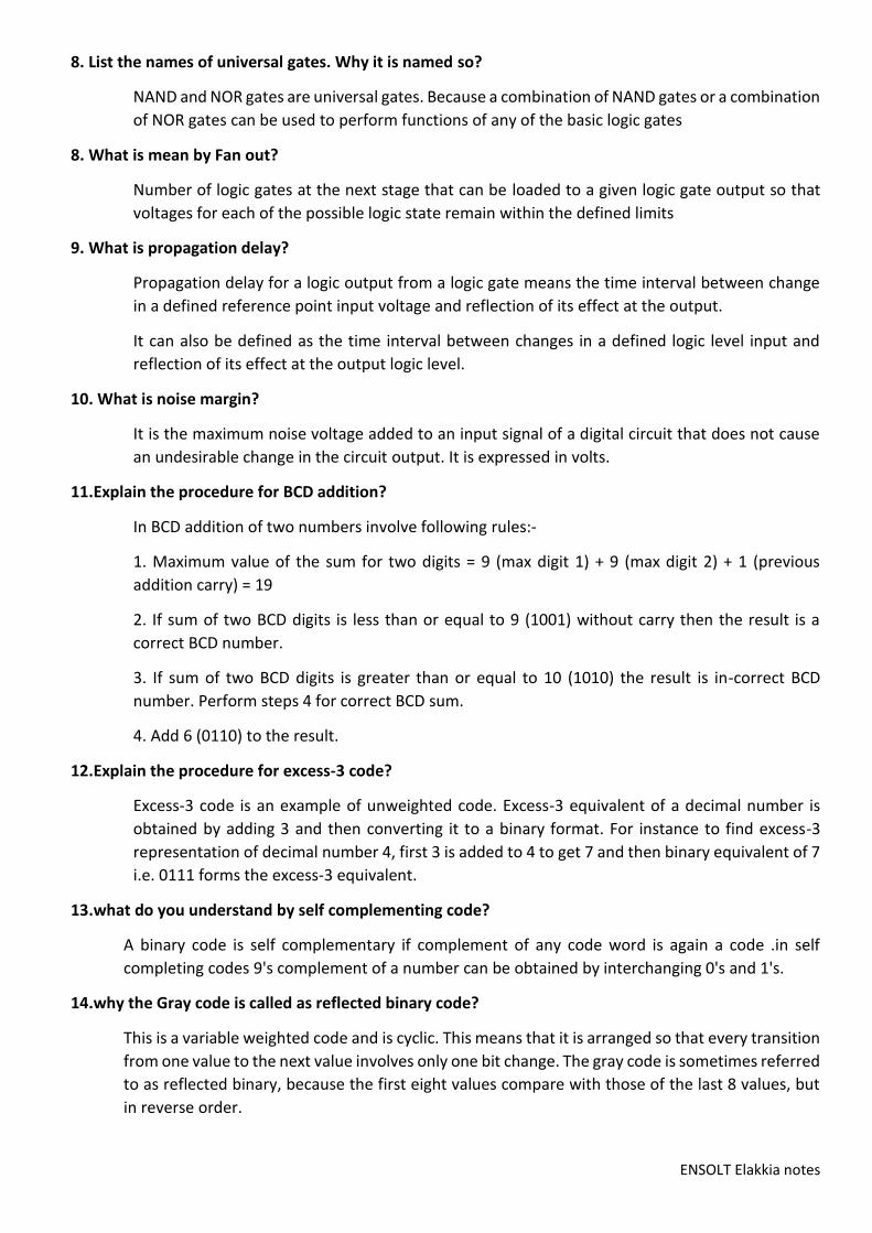
8. List the names of universal gates. Why it is named so?
NAND and NOR gates are universal gates. Because a combination of NAND gates or a combination
of NOR gates can be used to perform functions of any of the basic logic gates
8. What is mean by Fan out?
Number of logic gates at the next stage that can be loaded to a given logic gate output so that
voltages for each of the possible logic state remain within the defined limits
9. What is propagation delay?
Propagation delay for a logic output from a logic gate means the time interval between change
in a defined reference point input voltage and reflection of its effect at the output.
It can also be defined as the time interval between changes in a defined logic level input and
reflection of its effect at the output logic level.
10. What is noise margin?
It is the maximum noise voltage added to an input signal of a digital circuit that does not cause
an undesirable change in the circuit output. It is expressed in volts.
11.Explain the procedure for BCD addition?
In BCD addition of two numbers involve following rules:-
1. Maximum value of the sum for two digits = 9 (max digit 1) + 9 (max digit 2) + 1 (previous
addition carry) = 19
2. If sum of two BCD digits is less than or equal to 9 (1001) without carry then the result is a
correct BCD number.
3. If sum of two BCD digits is greater than or equal to 10 (1010) the result is in-correct BCD
number. Perform steps 4 for correct BCD sum.
4. Add 6 (0110) to the result.
12.Explain the procedure for excess-3 code?
Excess-3 code is an example of unweighted code. Excess-3 equivalent of a decimal number is
obtained by adding 3 and then converting it to a binary format. For instance to find excess-3
representation of decimal number 4, first 3 is added to 4 to get 7 and then binary equivalent of 7
i.e. 0111 forms the excess-3 equivalent.
13.what do you understand by self complementing code?
A binary code is self complementary if complement of any code word is again a code .in self
completing codes 9's complement of a number can be obtained by interchanging 0's and 1's.
14.why the Gray code is called as reflected binary code?
This is a variable weighted code and is cyclic. This means that it is arranged so that every transition
from one value to the next value involves only one bit change. The gray code is sometimes referred
to as reflected binary, because the first eight values compare with those of the last 8 values, but
in reverse order.

ENSOLT Elakkia notes
15. What is meant by non-weighted codes?
Each bit has no positional value i). Excess-3 code ii).Gray code iii).Five bit BCD
16. State advantages and disadvantages of TTL
Adv:Easily compatible with other ICs , Low output impedance
Disadv:
Wired output capability is possible only with tristate and open collector types
Special circuits in Circuit layout and system design are required.
Masked ROM.
Programmable Read only Memory
Erasable Programmable Read only memory.
Electrically Erasable Programmable Read only Memory.
17. Classify the logic family by operation?
The Bipolar logic family is classified into Saturated logic, Unsaturated logic. The RTL, DTL, TTL, I2L,
HTL logic comes under the saturated logic family. The Schottky TTL, and ECL logic comes under
the unsaturated logic family.
18. Mention the classification of saturated bipolar logic families.
The bipolar logic family is classified as follows:
RTL- Resistor Transistor Logic, DTL- Diode Transistor logic, I2L- Integrated Injection Logic.TTL-
Transistor Transistor Logic, ECL- Emitter Coupled Logic.
19. Mention the important characteristics of digital ICs?
Fan out, Power dissipation, Propagation Delay, Noise Margin , Fan In, Operating temperature
,Power supply requirements.
20. What is depletion mode& enhancement mode operation MOS?
If the channel is initially doped lightly with p-type impurity a conducting channel exists at zero
gate voltage and the device is said to operate in depletion mode. If the region beneath the gate
is left initially uncharged the gate field must induce a channel before current can flow. Thus the
gate voltage enhances the channel current and such a device is said to operate in the
enhancement mode.
21. What is depletion mode& enhancement mode operation MOS?
If the channel is initially doped lightly with p-type impurity a conducting channel exists at zero
gate voltage and the device is said to operate in depletion mode. If the region beneath the gate
is left initially uncharged the gate field must induce a channel before current can flow. Thus the
gate voltage enhances the channel cur`rent and such a device is said to operate in the
enhancement mode.

ENSOLT Elakkia notes
22. What is the feature of gray code? What are its applications
The advantage of gray code also called reflected code over pure binary numbers is that a number
in gray code changes by only one bit as it proceeds from one number to the next. A typical
application of the reflected code occurs when the analog data are represented by a continuous
change of a shaft position. The shaft is portioned into segments and each segment is assigned a
number. If adjacent segment are made to correspond to adjacent reflected-code numbers,
ambiguity is reduced when detection is sensed in the line that separates any two segments.
So in 3-bit code, error may occur due to one bit position, other two bit positions of adjacent
sectors are always same and hence there is no possibility of error. Thus in 3-bit code, probability
of error is reduced to 66 % and in 4-bit code it is reduced upto 25%.
23. What is even parity?
A parity bit is an extra bit included with a message to make the total number of 1’s either odd or
even. If the total number of 1’s is even then it is called even parity.
24. What are cyclic codes?
Cyclic codes are a special type of linear block code that are popular because they are very
effective for error detection and correction and their coders and decoders are easy to implement
in hardware
25. What is hamming code?
One of the most common method of error correcting .It consist of k parity bits that are added to
n-bit data word forming a new n+k bits.

ENSOLT Elakkia notes
UNIT II COMBINATIONAL CIRCUITS
1.Give the 2 canonical forms of Boolean function.
1. Sum of products 2. Product of sums
2. What is minterm & maxterm?
A product term containing all the „n‟ variables of the function in either complemented or
uncomplemented form is called minterm. A sum term containing all the „n‟ variables of the
function in either complemented or Uncomplemented form is called maxterm.
3.What is SOP, POS?
The sum of products expression consists of two or more product (AND) terms that are OR ed
together. Each product term consists of one or more literals in either complemented or
Uncomplemented form.
The product of sums expression consists of two or more sum (OR) terms that are AND ed
together. Each sum term consists of one or more literals in either complemented or
uncomplemented form.
4. What is a K- map?
Karnaugh map is a useful tool for simplifying and manipulating switching functions. It is a map
containing 2n cells for a „n‟ variable case. Each cell corresponds to one row of the truthtable.
5.What is prime implicant and non-prime implicant?
Prime implicant is a product term obtained by combining the maximum possible number of
adjacent squares in the K-map. It can not be enclosed by a larger implicant. Non prime implicant
can be enclosed by a larger group.
6.What is essential prime implicant?
If a minterm is covered by only one prime implicant that is said to be essential and it must be
included in the minimum sum of products.
7. What is incompletely specified functions/don‟t care conditions?
In certain digital systems some combinations of input variables do not occur. The outputs
corresponding to that input combinations do not matter. So the designer can assume a 0 or 1 as
output for each of these combinations. This condition is known as don‟t care conditions denoted
by X in K-map.
8. What are the limitations of K-map?
The map method is convenient as long as the number of variables does not exceed five or six. As
the number of variable increases, the excessive number of squares prevents a reasonable
selection of adjacent squares.

ENSOLT Elakkia notes
9. What is tabulation method?
The tabulation or Quine McCluskey method is a specific step by step procedure guaranteed to
produce a simplified standard form expression for a function. It can be applied to problems with
many variables and has the advantage of being suitable for machine computation.
10. What is the need for a code converter?
The availability of a large variety of codes for the same discrete elements of information results
in the use of different codes for different digital systems. It is
sometimes necessary to use the output of one system as the input to another. A conversion
circuit must be inserted between the two systems if each uses different codes for the same
information. Thus a code converter is a circuit that makes the two systems compatible even
though each uses a different binary code.
11.What are the steps to design a combinational logic circuit?
(1) The problem is stated
(2) The number of available input variables and required output variables is determined
(3) The input and output variables are assigned letter symbols
(4) The truth table that defines the required relationships between inputs and outputs is derived
(5) The simplified Boolean function for each output is obtained
(6) The logic diagram is drawn
12. What is an Encoder & Decoder?
An encoder is a combinational circuit that has 2n input lines and „n‟ output lines. The output
lines generate the binary code corresponding to the input value.eg. octal to binary encoder has
8 inputs and 3 outputs that generate the binary number corresponding to the octal digit.
The decoder is a combinational circuit that converts binary information from „n‟ input lines to a
maximum of 2n unique output lines. A binary code of n bits is capable of representing up to 2n
distinct elements.
13. What is a Multiplexer and Demultiplexer?
Multiplexing means transmitting a large number of information units over a smaller number of
channels or lines.
A digital Multiplexer (data selector) is a combinational circuit that selects binary information from
one of many input lines and directs it to a single output line. A Demultiplexer (data distributor) is
a combinational circuit that receives the information on a single line and transmits this
information on one of 2n possible output lines.
14. Mention the applications of Multiplexer.
1) Data selection and data routing. 2) Logic function generator.
3) Control sequencer. 4) Parallel to serial converter.

ENSOLT Elakkia notes
15. Compare decoder and Demultiplexer.
The Decoder is a combinational circuit that converts binary information from „n‟ input lines to a
maximum of 2n unique output lines. A Demultiplexer (data distributor) is a combinational circuit
that receives the information on a single line and transmits this information on one of 2n possible
output lines. A decoder with enable input can function as a Demultiplexer.

ENSOLT Elakkia notes
UNIT-III SYNCHRONOUS SEQUENTIAL CIRCUITS
1. What are the classifications of sequential circuits?
On the basis of timing of their signals 1) Synchronous sequential circuit. 2) Asynchronous sequential
circuit.
2. Define Flip flop.
The basic unit for storage is flip flop. A flip-flop maintains its output state either at 1 or 0 until
directed by an input signal to change its state.
3. What are the different types of flip-flop?
There are various types of flip flops. Some of them are mentioned below they are,
RS flip-flop
SR flip-flop
D flip-flop
JK flip-flop
T flip-flop
4. What is the operation of RS flip-flop?
When R input is low and S input is high the Q output of flip-flop is set.
When R input is high and S input is low the Q output of flip-flop is reset.
When both the inputs R and S are low the output does not change
When both the inputs R and S are high the output is unpredictable.
5. What is the operation of SR flip-flop?
When R input is low and S input is high the Q output of flip-flop is set.
When R input is high and S input is low the Q output of flip-flop is reset.
When both the inputs R and S are low the output does not change.
When both the inputs R and S are high the output is unpredictable.
6. What is the operation of D flip-flop?
In D flip-flop during the occurrence of clock pulse if D=1, the output Q is set and if D=0, the output
is reset.
7. What is the operation of JK flip-flop?
When K input is low and J input is high the Q output of flip-flop is set.
When K input is high and J input is low the Q output of flip-flop is reset.
When both the inputs K and J are low the output does not change

ENSOLT Elakkia notes
When both the inputs K and J are high it is possible to set or reset the Flip-flop (ie) the output toggle
on the next positive clock edge.
8. What is the operation of T flip-flop?
T flip-flop is also known as Toggle flip-flop.
When T=0 there is no change in the output.
When T=1 the output switch to the complement state (ie) the output toggles.
9. Define race around condition.
In JK flip-flop output is fed back to the input. Therefore change in the output results change in the
input. Due to this in the positive half of the clock pulse if both J and K are high then output toggles
continuously. This condition is called race around condition’.
10. What is edge-triggered flip-flop?
The problem of race around condition can solved by edge triggering flip flop. The term edge
triggering means that the flip-flop changes state either at the positive edge or negative edge of the
clock pulse and it is sensitive to its inputs only at this transition of the clock.
11. What is a master-slave flip-flop?
A master-slave flip-flop consists of two flip-flops where one circuit serves as a master and the other
as a slave.
12. Explain the flip-flop excitation tables for RS FF.
In RS flip-flop there are four possible transitions from the present state to the next state.
They are,
_0_0 transition: This can happen either when R=S=0 or when R=1 and S=0.
_0_1 transition: This can happen only when S=1 and R=0.
_1_0 transition: This can happen only when S=0 and R=1.
_1_1 transition: This can happen either when S=1 and R=0 or S=0 and R=0.
13. Explain the flip-flop excitation tables for JK flip-flop
In JK flip-flop also there are four possible transitions from present state to next state. They are,
_0_0 transition: This can happen when J=0 and K=1 or K=0.
_0_1 transition: This can happen either when J=1 and K=0 or when J=K=1.
_1_0 transition: This can happen either when J=0 and K=1 or when J=K=1.
_1_1 transition: This can happen when K=0 and J=0 or J=1.
14. Explain the flip-flop excitation tables for D flip-flop
In D flip-flop the next state is always equal to the D input and it is independent of the present state.
Therefore D must be 0 if Qn+1 has to 0, and if Qn+1 has to be 1 regardless the value of Qn.

ENSOLT Elakkia notes
15. Explain the flip-flop excitation tables for T flip-flop
When input T=1 the state of the flip-flop is complemented; when T=0, the state of the Flip-flop
remains unchanged. Therefore, for 0_0 and 1_1 transitions T must be 0 and for 0_1 and 1_0
transitions must be 1.
16. Define sequential circuit?
In sequential circuits the output variables dependent not only on the present input variables but
they also depend up on the past history of these input variables.
17. Give the comparison between combinational circuits and sequential circuits.
Combinational circuits Sequential circuits Memory unit is not required Memory unity is required.
Parallel adder is a combinational circuit Serial adder is a sequential circuit
18. What do you mean by present state?
The information stored in the memory elements at any given time defines the present state of the
sequential circuit.
19. What do you mean by next state?
The present state and the external inputs determine the outputs and the next state of the sequential
circuit.
20. State the types of sequential circuits?
1. Synchronous sequential circuits
2. Asynchronous sequential circuits
21. Define synchronous sequential circuit
In synchronous sequential circuits, signals can affect the memory elements only at discrete instant
of time.
22. Define Asynchronous sequential circuit?
In asynchronous sequential circuits change in input signals can affect memory element at any instant
of time.
23. Give the comparison between synchronous & Asynchronous sequential circuits?
Synchronous sequential circuits Asynchronous sequential circuits.
In this type of counter flip-flops are connected in such a way that output of 1st flip-flop drives the clock for the next flip- flop.
In this type there is no connection between output of first flip-flop and clock input of the next flip - flop
All the flip-flops are Not clocked simultaneously
All the flip-flops are clocked simultaneously
Design and implementation is very simple even for more number of state.
Design and implementation is tedious and complex as the number of state increases.
Low speed, as the clock is propagated through a number of FF before it reached last FF.
Faster, as the clock is applied to all FF simultaneously.

ENSOLT Elakkia notes
24. What is race around condition?
In the JK latch, the output is feedback to the input, and therefore changes in the output results
change in the input. Due to this in the positive half of the clock pulse if J and K are both high then
output toggles continuously. This condition is known as race around condition

ENSOLT Elakkia notes
UNIT-IV – First ASYNCHRONOUS SEQUENTIAL CIRCUITS
1. What are secondary variables?
Present state variables in asynchronous sequential circuits
2. What are excitation variables?
Next state variables in asynchronous sequential circuits
3. What is fundamental mode sequential circuit?
Input variables changes if the circuit is stable
Inputs are levels, not pulses
Only one input can change at a given time
4. What is pulse mode circuit?
Inputs are pulses
Widths of pulses are long for circuit to respond to the input
Pulse width must not be so long that it is still present after the new state is reached
5. What are the significance of state assignment?
In synchronous circuits-state assignments are made with the objective of circuit reduction
Asynchronous circuits-its objective is to avoid critical races
6. When does race condition occur?
Two or more binary state variables change their value in response to the change in I/p Variable
7. What is non critical race?
Final stable state does not depend on the order in which the state variable changes race condition
is not harmful
8. What is critical race?
Final stable state depends on the order in which the state variable changes -race condition is harmful
9. When does a cycle occur?
Asynchronous circuit makes a transition through a series of unstable state
10. What are the different techniques used in state assignment?
Shared row state assignment
One hot state assignment
11. What are the steps for the design of asynchronous sequential circuit?
Construction of primitive flow table -reduction of flow table
State assignment is made -realization of primitive flow table
12. What is hazard?

ENSOLT Elakkia notes
Unwanted switching transients
13. What is static 1 hazard?
Output goes momentarily 0 when it should remain at 1
14. What are static 0 hazards?
Output goes momentarily 1 when it should remain at 0
15. What is dynamic hazard?
Output changes 3 or more times when it changes from 1 to 0 or 0 to 1
16. What is the cause for essential hazards?
Unequal delays along 2 or more path from same input
17. What is flow table?
State table of a synchronous sequential network
18. What is SM chart?
Describes the behavior of a state machine used in hardware design of digital systems
19. What are the advantages of SM chart?
Easy to understand the operation
Easy to convert to several equivalent forms
20. What is primitive flow chart?
One stable state per row
21. What is state equivalence theorem?
Two states SA and SB, are equivalent if and only if for every possible input X sequence, the outputs
are the same and the next states are equivalent i.e.,
if SA (t + 1) = SB (t + 1) and ZA = ZB then SA = SB.
22. What do you mean by distinguishing sequences?
Two states, SA and SB of sequential machine are distinguishable if and only if their exists at least
one finite input sequence. Which, when applied to sequential machine causes different output
sequences depending on whether SA or SB is the initial state.
23. Prove that the equivalence partition is unique
Consider that there are two equivalence partitions exist: PA and PB, and PA) PB. This states that,
there exist 2 states Si & Sj which are in the same block of one partition and not in the same block of
the other. If Si & Sj are in different blocks of say PB, there exists at least on input sequence which
distinguishes Si & Sj and therefore, they cannot be in the same block of PA.
24. Define compatibility.

ENSOLT Elakkia notes
States Si and Sj said to be compatible states, if and only if for every input sequence that affects the
two states, the same output sequence, occurs whenever both outputs are specified and regardless
of whether Si on Sj is the initial state.
25. Define merger graph.
The merger graph is defined as follows. It contains the same number of vertices as the state table
contains states. A line drawn between the two state vertices indicates each compatible state pair. It
two states are incompatible no connecting line is drawn.
26. Define incompatibility
The states are said to be incompatible if no line is drawn in between them. If implied states are
incompatible, they are crossed & the corresponding line is ignored
27. Explain the procedure for state minimization.
1. Partition the states into subsets such that all states in the same subsets are 1 equivalent.
2. Partition the states into subsets such that all states in the same subsets are 2 equivalent.
3. Partition the states into subsets such that all states in the same subsets are 3 equivalent.
28. Define closed covering.
A Set of compatibles is said to be closed if, for every compatible contained in the set, all its implied
compatibles are also contained in the set. A closed set of compatibles, which contains all the states
of M, is called a closed covering.
29. Define machine equivalence.
Two machines, M1 and M2 are said to be equivalent if and only if, for every state in M1, there is a
corresponding equivalent state in M2 & vice versa.
30. Define state table.
For the design of sequential counters we have to relate present states and next states. The table,
which represents the relationship between present states and next states, is called state table.
31. Define total state.
The combination of level signals that appear at the inputs and the outputs of the delays define what
is called the total state of the circuit.
32. What are the steps for the design of asynchronous sequential circuit?
1. Construction of a primitive flow table from the problem statement.
2. Primitive flow table is reduced by eliminating redundant states using the state Reduction
3. State assignment is made
4. The primitive flow table is realized using appropriate logic elements.
33. Define primitive flow table.
It is defined as a flow table which has exactly one stable state for each row in the table. The design
process begins with the construction of primitive flow table.

ENSOLT Elakkia notes
34. What are the types of asynchronous circuits?
1. Fundamental mode circuits
2. Pulse mode circuits
35. Give the comparison between state Assignment Synchronous circuit and state assignment
asynchronous circuit.
In synchronous circuit, the state assignments are made with the objective of circuit reduction. In
asynchronous circuits, the objective of state assignment is to avoid critical races.
36. What are races?
When 2 or more binary state variables change their value in response to a change in an input
variable, race condition occurs in an asynchronous sequential circuit. In case of unequal delays, a
race condition may cause the state variables to change in an unpredictable manner.
37. Define non critical race.
If the final stable state that the circuit reaches does not depend on the order in which the state
variable changes, the race condition is not harmful and it is called a non critical race.
38. Define critical race?
If the final stable state depends on the order in which the state variable changes, the race condition
is harmful and it is called a critical race.
39. What is a cycle?
A cycle occurs when an asynchronous circuit makes a transition through a series of unstable states.
If a cycle does not contain a stable state, the circuit will go from one unstable to stable to another,
until the inputs are changed.
40. List the different techniques used for state assignment.
1. Shared row state assignment
2. One hot state assignment.
41. Write a short note on fundamental mode asynchronous circuit.
Fundamental mode circuit assumes that. The input variables change only when the circuit is stable.
Only one input variable can change at a given time and inputs are levels and not pulses.
42. Write a short note on pulse mode circuit.
Pulse mode circuit assumes that the input variables are pulses instead of level. The width of the
pulses is long enough for the circuit to respond to the input and the pulse width must not be so long
that it is still present after the new state is reached.

ENSOLT Elakkia notes
43. Write short note on shared row state assignment.
Races can be avoided by making a proper binary assignment to the state variables. Here, the state
variables are assigned with binary numbers in such a way that only one state variable can change at
any one state variable can change at any one time when a state transition occurs. To accomplish
this, it is necessary that states between which transitions occur be given adjacent assignments. Two
binary are said to be adjacent if they differ in only one variable.
44. Write short note on one hot state assignment.
The one hot state assignment is another method for finding a race free state assignment. In this
method, only one variable is active or hot for each row in the original flow table, ie, it requires one
state variable for each row of the flow table. Additional row are introduced to provide single variable
changes between internal state transitions.

ENSOLT Elakkia notes
UNIT-IV – Second PROGRAMMABLE LOGIC DEVICES, MEMORY AND LOGIC FAMILIES
1. Explain ROM
A read only memory (ROM) is a device that includes both the decoder and the OR gates within a
single IC package. It consists of n input lines and m output lines. Each bit Combination of the input
variables is called an address. Each bit combination that comes out of the output lines is called a
word. The number of distinct addresses possible with n input variables is 2n.
2. What are the types of ROM?
1. PROM
2. EPROM
3. EEPROM
3. Explain PROM.
PROM (Programmable Read Only Memory) it allows user to store data or program. PROMs use the
fuses with material like nichrome and polycrystalline. The user can blow these fuses by pass in
around 20 to 50 mA of current for the period 5 to 20 μs. The blowing of fuses is called programming
of ROM. The PROMs are one time programmable. Once programmed, the information is stored
permanent.
4. Explain EPROM.
EPROM (Erasable Programmable Read Only Memory) EPROM use MOS circuitry. They store 1’s and
0’s as a packet of charge in a buried layer of the IC chip. We can erase the stored data in the EPROMs
by exposing the chip to ultraviolet light via its quartz window for 15 to 20 minutes. It is not possible
to erase selective information. The chip can be reprogrammed.
5. Explain EEPROM.
EEPROM (Electrically Erasable Programmable Read Only Memory). EEPROM also use MOS circuitry.
Data is stored as charge or no charge on an insulated layer or an insulated floating gate in the device.
EEPROM allows selective erasing at the register level rather than erasing all the information since
the information can be changed by using electrical signals.
6. Define address and word:
In a ROM, each bit combination of the input variable is called on address. Each bit combination that
comes out of the output lines is called a word.
7. What are the types of ROM.?
1. Masked ROM.
2. Programmable Read only Memory
3. Erasable Programmable Read only memory.
4. Electrically Erasable Programmable Read only Memory.
8. What is programmable logic array? How it differs from ROM?

ENSOLT Elakkia notes
In some cases the number of don’t care conditions is excessive, it is more economical to use a second
type of LSI component called a PLA. A PLA is similar to a ROM in concept; however it does not provide
full decoding of the variables and does not generates all the min terms as in the ROM.
9. What is mask - programmable?
With a mask programmable PLA, the user must submit a PLA program table to the manufacturer.
10. What is field programmable logic array?
The second type of PLA is called a field programmable logic array. The user by means of certain
recommended procedures can program the EPLA.
11. List the major differences between PLA and PAL
PLA: Both AND and OR arrays are programmable and Complex Costlier than PAL
PAL : AND arrays are programmable OR arrays are fixed Cheaper and Simpler
12. Define PLD.
Programmable Logic Devices consist of a large array of AND gates and OR gates that Can be
programmed to achieve specific logic functions.
13. Give the classification of PLDs.
PLDs are classified as PROM (Programmable Read Only Memory), Programmable Logic Array (PLA),
Programmable Array Logic (PAL), and Generic Array Logic (GAL)
14. Define PROM.
PROM is Programmable Read Only Memory. It consists of a set of fixed AND gates Connected to a
decoder and a programmable OR array.
15. Define PLA.
PLA is Programmable Logic Array (PLA). The PLA is a PLD that consists of a Programmable AND array
and a programmable OR array.
16. Define PAL.
PAL is Programmable Array Logic. PAL consists of a programmable AND array and a fixed OR array
with output logic.
17. Why was PAL developed?
It is a PLD that was developed to overcome certain disadvantages of PLA, such as longer delays due
to additional fusible links that result from using two programmable arrays and more circuit
complexity.
18. Define GAL.
GAL is Generic Array Logic. GAL consists of a programmable AND array and a fixed OR array with
output logic.
19. Why the input variables to a PAL are buffered
The input variables to a PAL are buffered to prevent loading by the large number of AND gate inputs
to which available or its complement can be connected.

ENSOLT Elakkia notes
20. What does PAL 10L8 specify?
PAL - Programmable Logic Array
10 - Ten inputs
L - Active LOW Ouput
8 - Eight Outputs
21. What is CPLD?
CPLDs are Complex Programmable Logic Devices. They are larger versions of PLDs with a centralized
internal interconnect matrix used to connect the device macro cells together.
22. Define bit, byte and word.
The smallest unit of binary data is bit. Data are handled in a 8 bit unit called byte. A complete unit
of information is called a word which consists of one or more bytes.
23. How many words can a 16x8 memory can store?
A 16x8 memory can store 16,384 words of eight bits each
24. Define address of a memory.
The location of a unit of data in a memory is called address.
25. What is Read and Write operation?
The Write operation stores data into a specified address into the memory and the Read operation
takes data out of a specified address in the memory.
26. Why RAMs are called as Volatile?
RAMs are called as Volatile memories because RAMs lose stored data when the power is turned
OFF.
27. Define ROM.
ROM is a type of memory in which data are stored permanently or semi permanently. Data can be
read from a ROM, but there is no write operation.

ENSOLT Elakkia notes
28. Define RAM.
RAM is Random Access Memory. It is a random access read/write memory. The data can be read or
written into from any selected address in any sequence.
29. Define Static RAM and dynamic RAM.
Static RAM use flip flops as storage elements and therefore store data indefinitely as long as dc
power is applied. Dynamic RAMs use capacitors as storage elements and cannot retain data very
long without capacitors being recharged by a process called refreshing.
30. List the two types of SRAM.
Asynchronous SRAMs and Synchronous Burst SRAMs
31. List the basic types of DRAMs.
Fast Page Mode DRAM, Extended Data Out DRAM (EDO DRAM),Burst EDO DRAM and Synchronous
DRAM.
32. Define a bus.
A bus is a set of conductive paths that serve to interconnect two or more functional components of
a system or several diverse systems.
33. Define Cache memory.
It is a relatively small, high-speed memory that can store the most recently used instructions or data
from larger but slower main memory.
34. What is the technique adopted by DRAMs.
DRAMs use a technique called address multiplexing to reduce the number of address lines.
35. Give the feature of UV EPROM.
UV EPROM is electrically programmable by the user, but the store data must be erased by exposure
to ultra violet light over a period of several minutes.
36. Give the feature of flash memory.
The ideal memory has high storage capacity, non-volatility; in-system read and write capability,
comparatively fast operation. The traditional memory technologies such as ROM, PROM, EEPROM
individually exhibits one of these characteristics, but no single technology has all of them except the
flash memory.
37. What are Flash memories?
They are high density read/write memories that are non-volatile, which means data can be stored
indefinitely with out power.
38. List the three major operations in a flash memory.
Programming, Read and Erase operation

ENSOLT Elakkia notes
39. What is a FIFO memory?
The term FIFO refers to the basic operation of this type of memory in which the first data bit written
into the memory is to first to be read out.
40. List basic types of programmable logic devices.
1. Read only memory
2. Programmable logic Array
3. Programmable Array Logic
41. Define address and word.
In a ROM, each bit combination of the input variable is called on address. Each bit combination that
comes out of the output lines is called a word.
42. What is programmable logic array? How it differs from ROM?
In some cases the number of don’t care conditions is excessive, it is more economical to use a second
type of LSI component called a PLA. A PLA is similar to a ROM in concept; however it does not provide
full decoding of the variables and does not generates all the min terms as in the ROM.
43. What is mask - programmable?
With a mask programmable PLA, the user must submit a PLA PLA program table to the manufacturer.
45. Mention the classification of saturated bipolar logic families.
The bipolar logic family is classified as follows:
RTL- Resistor Transistor Logic
DTL- Diode Transistor logic
I2L- Integrated Injection Logic
TTL- Transistor Transistor Logic
ECL- Emitter Coupled Logic
46. Mention the important characteristics of digital IC’s?
Fan out, Power dissipation, Propagation Delay, Noise Margin, Fan In, Operating temperature, Power
supply requirements
47. Define Fan-out?
Fan out specifies the number of standard loads that the output of the gate can drive without
impairment of its normal operation.
48. Define power dissipation?
Power dissipation is measure of power consumed by the gate when fully driven by all its inputs.
49. What is propagation delay?
Propagation delay is the average transition delay time for the signal to propagate from input to
output when the signals change in value. It is expressed in ns.

ENSOLT Elakkia notes
50. Define noise margin?
It is the maximum noise voltage added to an input signal of a digital circuit that does not cause an
undesirable change in the circuit output. It is expressed in volts.
51. Define fan in?
Fan in is the number of inputs connected to the gate without any degradation in the voltage level.
52. What is Operating temperature?
All the gates or semiconductor devices are temperature sensitive in nature. The temperature in
which the performance of the IC is effective is called as operating temperature. Operating
temperature of the IC vary from 00C to 700C.
53. What is High Threshold Logic?
Some digital circuits operate in environments, which produce very high noise signals. For operation
in such surroundings there is available a type of DTL gate which possesses a high threshold to noise
immunity. This type of gate is called HTLlogic or High Threshold Logic.
54. What are the types of TTL logic?
1. Open collector output 2. Totem-Pole Output 3. Tri-state output.
55. What is depletion mode operation MOS?
If the channel is initially doped lightly with p-type impurity a conducting channel exists at zero gate
voltage and the device is said to operate in depletion mode.
56. What is enhancement mode operation of MOS?
If the region beneath the gate is left initially uncharged the gate field must induce a channel before
current can flow. Thus the gate voltage enhances the channel current and such a device is said to
operate in the enhancement mode.
57. Mention the characteristics of MOS transistor?
1. The n- channel MOS conducts when its gate- to- source voltage is positive.
2. The p- channel MOS conducts when its gate- to- source voltage is negative
3. Either type of device is turned of if its gate- to- source voltage is zero.
58. How schottky transistors are formed and state its use?
A schottky diode is formed by the combination of metal and semiconductor. The presence of
schottky diode between the base and the collector prevents the transistor from going into
saturation. The resulting transistor is called as schottky transistor. The use of schottky transistor in
TTL decreases the propagation delay without a sacrifice of power dissipation.
ENSOLT Elakkia notes
59. List the different versions of TTL
TTL (Std.TTL)
LTTL (Low PowerTTL)
HTTL (High Speed TTL)
STTL (Schottky TTL)
LSTTL (Low power Schottky TTL)
60. Why totem pole outputs cannot be connected together.
Totem pole outputs cannot be connected together because such a connection might produce
excessive current and may result in damage to the devices.
61. State advantages and disadvantages of TTL
Adv: Easily compatible with other ICs Low output impedance
Disadv: Wired output capability is possible only with tristate and open collector types Special circuits
in Circuit layout and system design are required.
62. When does the noise margin allow digital circuits to function properly?
When noise voltages are within the limits of VNA (High State Noise Margin) and VNK for a particular
logic family.
63. What happens to output when a tristate circuit is selected for high impedance.
Output is disconnected from rest of the circuits by internal circuitry.

ENSOLT Elakkia notes
UNIT-V VHDL
TWO MARKS
1. What is Verilog?
Verilog is a general purpose hardware descriptor language. It is similar in syntax to the C
programming language. It can be used to model a digital system at many levels of abstraction
ranging from the algorithmic level to the switch level.
2. What are the various modeling used in Verilog?
1. Gate-level modeling
2. Data-flow modeling
3. Switch-level modeling
4. Behavioral modeling
3. What is the structural gate-level modeling?
Structural modeling describes a digital logic networks in terms of the components that make up the
system. Gate-level modeling is based on using primitive logic gates and specifying how they are
wired together.
4. What is Switch-level modeling?
Verilog allows switch-level modeling that is based on the behavior of MOSFETs. Digital circuits at the
MOS-transistor level are described using the MOSFET switches.
5. What are identifiers?
Identifiers are names of modules, variables and other objects that we can reference in the design.
Identifiers consists of upper and lower case letters, digits 0 through 9, the underscore character(_)
and the dollar sign($). It must be a single group of characters.
Examples: A014, a, b, in_o, s_out
6. What are the value sets in Verilog?
Verilog supports four levels for the values needed to describe hardware referred to as value sets.
Value levels Condition in hardware circuits
0 Logic zero, false condition
1 Logic one, true condition
X Unknown logic value
Z High impedance, floating state

ENSOLT Elakkia notes
7. What are the types of gate arrays in ASIC?
1) Channeled gate arrays
2) Channel less gate arrays
3) Structured gate arrays
8. Give the classifications of timing control
Methods of timing control:
1. Delay-based timing control
2. Event-based timing control
3. Level-sensitive timing control
Types of delay-based timing control:
1. Regular delay control
2. Intra-assignment delay control
3. Zero delay control
Types of event-based timing control:
1. Regular event control
2. Named event control
3. Event OR control
4. Level-sensitive timing control
9 .Give the different arithmetic operators?
Operator symbol Operation performed Number of operands
* Multiply Two
/ Divide Two
+ Add Two
- Subtract Two
% Modulus Two
** Power (exponent) Two

ENSOLT Elakkia notes
10. Give the different bitwise operators.
Operator symbol Operation performed Number of operands
~ Bitwise negation One
& Bitwise and Two
| Bitwise or Two
^ Bitwise xor Two
^~ or ~^ Bitwise xnor Two
~& Bitwise nand Two
~| Bitwise nor Two
11. What are gate primitives?
Verilog supports basic logic gates as predefined primitives. Primitive logic function keyword provides
the basics for structural modeling at gate level. These primitives are instantiated like modules except
that they are predefined in verilog and do not need a module definition. The important operations
are and, nand, or, xor, xnor, and buf(non-inverting drive buffer).
12. Give the two blocks in behavioral modeling.
1. An initial block executes once in the simulation and is used to set up initial conditions and step-
by-step data flow.
2. An always block executes in a loop and repeats during the simulation.
13. What are the types of conditional statements?
1. No else statement
Syntax: if ([expression]) true – statement;
2. One else statement
Syntax: if ([expression]) true – statement; else false-statement;
3. Nested if-else-if
Syntax : if ( [expression1] ) true statement 1;
else if ( [expression2] ) true-statement 2;
else if ( [expression3] ) true-statement 3;
else default-statement;
The [expression] is evaluated. If it is true (1 or a non-zero value) true-statement is executed. If it is
false (zero) or ambiguous (x), the false-statement is executed.
ENSOLT Elakkia notes
14. Name the types of ports in Verilog
Types of port Keyword
Input port Input
Output port Output
Bidirectional port inout
15. What are the types of procedural assignments?
1. Blocking assignment
2. Non-blocking assignment