TU510A Auto Transfer Controller Operation Manual · Manual HM1043ER1 Outline Dimensional Drawings...
32
Manual TU510A Auto Transfer Controller HM1043ER1 Harsen ®
Transcript of TU510A Auto Transfer Controller Operation Manual · Manual HM1043ER1 Outline Dimensional Drawings...
Manual
TU510A Auto Transfer Controller
HM1043ER1
Harsen®
Manual HM1043ER1 History
Harsen® I
History
No. Rev. Date Editor Validation Changes
1 HM1043ER1 2011.1.1 P.L New
Manual HM1043ER1 Contents
Harsen® I
Contents
Description ................................................................................................................................................
1. The Outline Dimensional Drawings and wirings of Intelligent Controller...........................................
2. Operation Panel .................................................................................................................................
3. Installation Guide ................................................................................................................................
4. Control and Operation Instruction .................................................................................................
5. Measure and Display Data ...............................................................................................................
6. Alarm ....................................................................................................................................................
7. Parameters Setting .............................................................................................................................
8. Communication Function....................................................................................................................
9. Technical Parameters.........................................................................................................................
10. Troubleshooting .................................................................................................................................
1
2
12
16
17
20
21
22
24
27
28
Manual HM1043ER1 Description
Harsen® Page 1/28
Description TU510A controller is an auto transfer controller, which incorporating the functions such as measuring display, control, and three remote. This controller covers three models: TU510A-MG/MM/GG, respectively used for auto transfer control of the dual power system, such as Mains and Gen, Mains and Mains, Gen and Gen. It has following functions:
l Micro-computer control, complete digital technology. l Select the running mode of controller by buttons on panel. l LED directly displays the running status of ATS and the running mode of controller. l Configure the running parameters by LED and buttons on panel. l Display measuring data by LED, including voltage and frequency. l By connecting RS485 communication port to PC (required for RS485/RS232 interface converter)
all setting values and data can be read and wrote, and modified. This manual is only suitable for TU510A auto transfer controller; user must carefully read this manual first.
The descriptions in this manual, to describe expediently and avoid repetition and redundance, are defined as following: 1.
General Designation TU510A-MG TU510A-GG TU510A-MM 1# power source Mains 1# Gen 1# Mains 2# power source Gen 2# Gen 2# Mains
2.
Shortened form Models MG model TU510A-MG GG model TU510A-GG MM model TU510A-MM
Manual HM1043ER1 Outline Dimensional Drawings and wirings
Harsen® Page 2/28
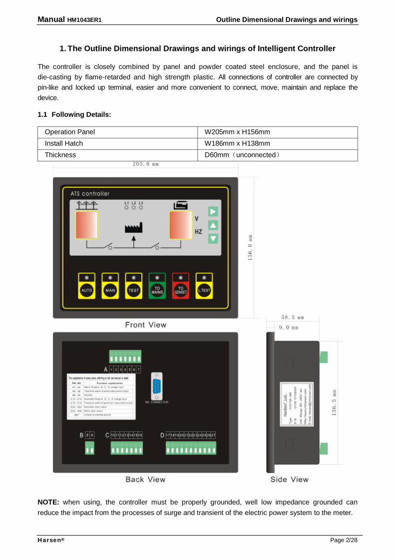
1. The Outline Dimensional Drawings and wirings of Intelligent Controller The controller is closely combined by panel and powder coated steel enclosure, and the panel is die-casting by flame-retarded and high strength plastic. All connections of controller are connected by pin-like and locked up terminal, easier and more convenient to connect, move, maintain and replace the device. 1.1 Following Details:
Operation Panel W205mm x H156mm Install Hatch W186mm x H138mm Thickness D60mm(unconnected)
NOTE: when using, the controller must be properly grounded, well low impedance grounded can reduce the impact from the processes of surge and transient of the electric power system to the meter.
Manual HM1043ER1 Outline Dimensional Drawings and wirings
Harsen® Page 3/28
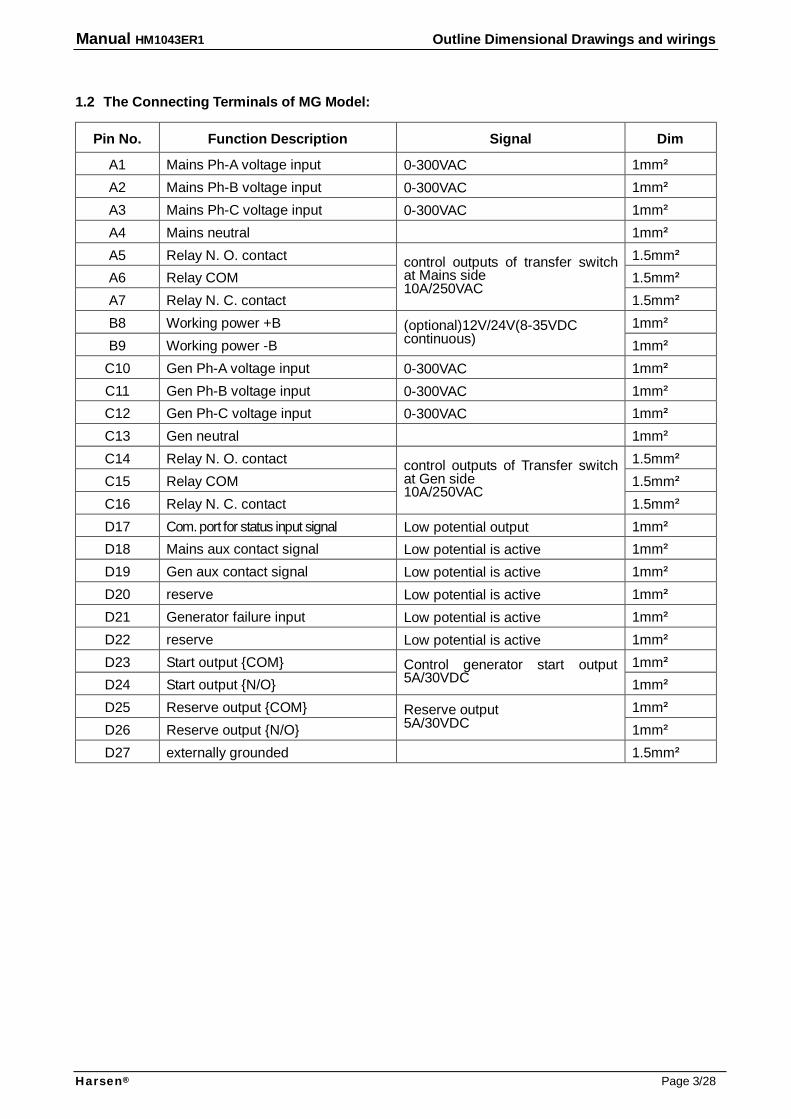
1.2 The Connecting Terminals of MG Model:
Pin No. Function Description Signal Dim
A1 Mains Ph-A voltage input 0-300VAC 1mm² A2 Mains Ph-B voltage input 0-300VAC 1mm² A3 Mains Ph-C voltage input 0-300VAC 1mm² A4 Mains neutral 1mm² A5 Relay N. O. contact 1.5mm² A6 Relay COM 1.5mm² A7 Relay N. C. contact
control outputs of transfer switch at Mains side 10A/250VAC
1.5mm² B8 Working power +B 1mm² B9 Working power -B
(optional)12V/24V(8-35VDC continuous) 1mm²
C10 Gen Ph-A voltage input 0-300VAC 1mm² C11 Gen Ph-B voltage input 0-300VAC 1mm² C12 Gen Ph-C voltage input 0-300VAC 1mm² C13 Gen neutral 1mm² C14 Relay N. O. contact 1.5mm² C15 Relay COM 1.5mm² C16 Relay N. C. contact
control outputs of Transfer switch at Gen side 10A/250VAC
1.5mm² D17 Com. port for status input signal Low potential output 1mm² D18 Mains aux contact signal Low potential is active 1mm² D19 Gen aux contact signal Low potential is active 1mm² D20 reserve Low potential is active 1mm² D21 Generator failure input Low potential is active 1mm² D22 reserve Low potential is active 1mm² D23 Start output {COM} 1mm² D24 Start output {N/O}
Control generator start output 5A/30VDC 1mm²
D25 Reserve output {COM} 1mm² D26 Reserve output {N/O}
Reserve output 5A/30VDC 1mm²
D27 externally grounded 1.5mm²

Manual HM1043ER1 Outline Dimensional Drawings and wirings
Harsen® Page 4/28
1.3 The typical wiring diagram of MG Model
3
F2
F1
F4
12
46
57
N3L8
L9
L7
19
18
17
27
TU51
0a-
MG
M1/M2
(aux contact)
RL1
Load
(3P&N)
F8
1614
15
F7
F6
F5
L4
L6
N2
L5
11
10
13
12
89
RL2
(2A) (
8-35VDC)
AC resource(standby)
F9
24
RL4
23
Genset start signal
(3P&N)
Gen
M2
M1
Note:
con
tro
lle
r mu
st
be
grou
nde
d p
rope
rly
L1 L3
F3
N1L2
(3P&N)
Mai
ns
It is used for the transfer switch of TGME or AC connector type.
Manual HM1043ER1 Outline Dimensional Drawings and wirings
Harsen® Page 5/28
1011
L5 N2L6L4
F5
F6
F7
15
14
16
XF
MNMT
MX
F8
(3P&N)
Load
RL1
TU510a-MG
XF
(cl
ose)
MN
(no v
olt
age
)
MT
(Stor
age
mo
tor
)
MX (
de-
exc
ite
r)
L7
Note:
L9L8
N3
7
RL2
12
13
MN
XF
MT
MX
56
42
1
F4
F1
F2
3
Main
s(3P&N)
L2 N1
F3
L3L1
Gens
et
sta
rt
sig
nal
23
RL4
24
F9
DC r
esource(standby)
(8-35VDC)
(2A
)
98
(aux contact for transform switch)
M1/M2
2717
1819
(3P&N)
Gen
Note: controller must be grounded properly
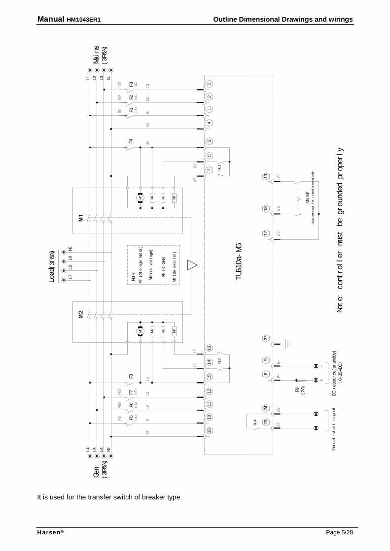
It is used for the transfer switch of breaker type.

Manual HM1043ER1 Outline Dimensional Drawings and wirings
Harsen® Page 6/28
1.4 The Connecting Terminals of GG Model:
Pin No. Function Description Signal Dim
A1 1# Gen Ph-A voltage input 0-300VAC 1mm² A2 1# Gen Ph-B voltage input 0-300VAC 1mm² A3 1# Gen Ph-C voltage input 0-300VAC 1mm² A4 1# Gen neutral 1mm² A5 Relay N. O. contact 1.5mm² A6 Relay COM 1.5mm² A7 Relay N. C. contact
transfer switch at 1# Gen side controls output 10A/250VAC
1.5mm² B8 Working power +B 1mm² B9 Working power -B
12V/24V (8-35VDC continuous) 1mm²
C10 2# Gen Ph-A voltage input 0-300VAC 1mm² C11 2# Gen Ph-B voltage input 0-300VAC 1mm² C12 2# Gen Ph-C voltage input 0-300VAC 1mm² C13 2# Gen neutral 1mm² C14 Relay N. O. contact 1.5mm² C15 Relay COM 1.5mm² C16 Relay N. C. contact
Control outputs of transfer switch at 2# Gen side output 10A/250VAC 1.5mm²
D17 COM. port for status input signal Low potential output 1mm² D18 1# Gen aux contact signal Low potential is active 1mm² D19 2# Gen aux contact signal Low potential is active 1mm² D20 1# generator failure input Low potential is active 1mm² D21 2# generator failure input Low potential is active 1mm² D22 Remote start input Low potential is active 1mm² D23 2# start output {COM} 1mm² D24 2# start output {N/O}
Control 2# generator start output 5A/30VDC 1mm²
D25 1# start output {COM} 1mm² D26 1# start output {N/O}
Control 1# generator start output 5A/30VDC 1mm²
D27 externally grounded 1.5mm²
Manual HM1043ER1 Outline Dimensional Drawings and wirings
Harsen® Page 7/28
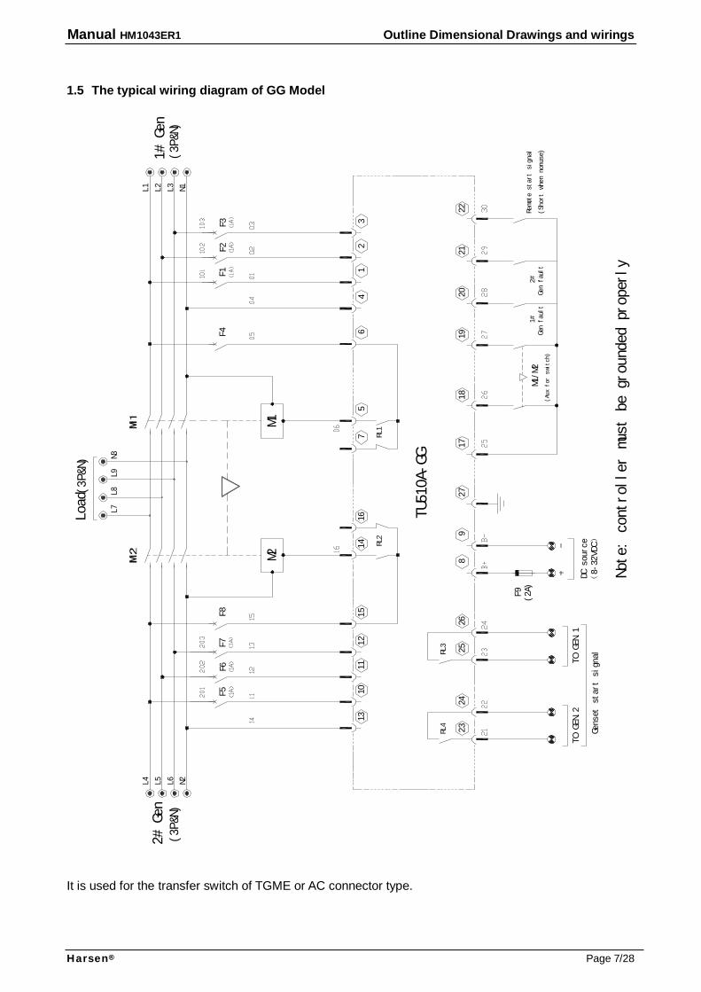
1.5 The typical wiring diagram of GG Model
21
2#
20
1918
1#
M1/M
2
1727
89
26
RL3
25
24
(2A
)
TO
GEN.
1
F9
RL4
23
TO G
EN.2
(3P
&N)
(8-32VDC)
M1
M2
RL2
12
1310
11
L5 N2L6L4
F5
F6F7
15
14
16
F8
(3P&
N)
RL1
L7L9
L8N3
75
64
21
F4
F1
F2
3
L2
N1
F3
L3
L1
TU510A-GG
Note: controller must be grounded properly
Genset
st
art
sign
al
(Au
x f
or s
wit
ch)
Load
1# Gen
2# Gen
Gen fault
Gen fault
DC sou
rce
Remote start signal
(Short when nonuse)(3P
&N)
22
It is used for the transfer switch of TGME or AC connector type.

Manual HM1043ER1 Outline Dimensional Drawings and wirings
Harsen® Page 8/28
(3P&
N)
RL2
13
11
10
L5
N2
L6
L4
F5
F6
14
12
15
16
MN XFMT MX
F7
F8
1# Gen
TU51
0A-GG
MN (no voltage)
MT (storage motor)
XF (close)
MX (de-exciter)
Note:
L7
L9
L8
XFMNMT MX
N3
RL1
75
61
4
F4F1
23
L2
F2F3
N1
L3
L1
(3P
&N)
DC
sour
ce
(8-3
5VD
C)
Gens
et
star
t s
ign
al
TO GE
N.2
23
RL4
F9
TO G
EN.1
(2A)
24
25
RL3
26
Gen fault
98
27
17
(aux for switch)
M1/M2
1#
Gen fault
18
19
20
2#
(Short when nonuse)
Remote start signal
21
22
Load (
3P&N
)
2# G
en
Note:
co
ntr
oller
mu
st
be gr
oun
ded
prop
erl
y
It is used for the transfer switch of breaker type.
Manual HM1043ER1 Outline Dimensional Drawings and wirings
Harsen® Page 9/28
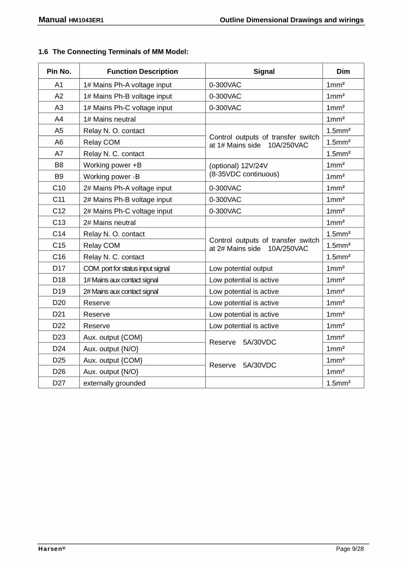
1.6 The Connecting Terminals of MM Model:
Pin No. Function Description Signal Dim
A1 1# Mains Ph-A voltage input 0-300VAC 1mm² A2 1# Mains Ph-B voltage input 0-300VAC 1mm² A3 1# Mains Ph-C voltage input 0-300VAC 1mm² A4 1# Mains neutral 1mm² A5 Relay N. O. contact 1.5mm² A6 Relay COM 1.5mm² A7 Relay N. C. contact
Control outputs of transfer switch at 1# Mains side 10A/250VAC
1.5mm² B8 Working power +B 1mm² B9 Working power -B
(optional) 12V/24V (8-35VDC continuous) 1mm²
C10 2# Mains Ph-A voltage input 0-300VAC 1mm² C11 2# Mains Ph-B voltage input 0-300VAC 1mm² C12 2# Mains Ph-C voltage input 0-300VAC 1mm² C13 2# Mains neutral 1mm² C14 Relay N. O. contact 1.5mm² C15 Relay COM 1.5mm² C16 Relay N. C. contact
Control outputs of transfer switch at 2# Mains side 10A/250VAC
1.5mm² D17 COM. port for status input signal Low potential output 1mm² D18 1# Mains aux contact signal Low potential is active 1mm² D19 2# Mains aux contact signal Low potential is active 1mm² D20 Reserve Low potential is active 1mm² D21 Reserve Low potential is active 1mm² D22 Reserve Low potential is active 1mm² D23 Aux. output {COM} 1mm² D24 Aux. output {N/O}
Reserve 5A/30VDC 1mm²
D25 Aux. output {COM} 1mm² D26 Aux. output {N/O}
Reserve 5A/30VDC 1mm²
D27 externally grounded 1.5mm²

Manual HM1043ER1 Outline Dimensional Drawings and wirings
Harsen® Page 10/28
1.7 The typical wiring diagram of MM Model: Lo
ad
2# M
ain
s
(3P&N)
1# M
ain
s(3P
&N)
1918
M1/M2
17
(3P&N)
M1M2
RL2
1213
1011
L5
N2
L6
L4
F5
F6
F7
1514
16
F8
(3P&N)
RL1
L7
L9
L8
N3
75
64
21
F4F1
F2
3
L2
N1
F3
L3
L1
TU510A-MM
Note: controller must be grounded properly
(Aux
for
swit
ch)
It is used for the transfer switch of TGME or AC connector type.
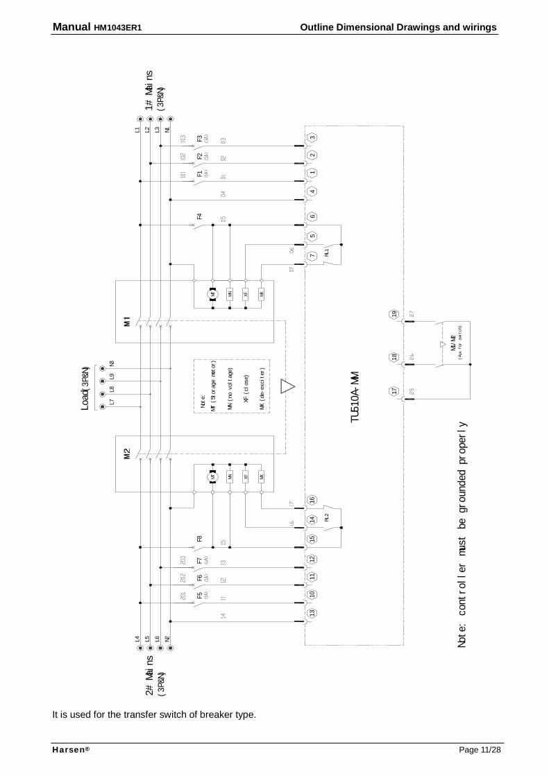
Manual HM1043ER1 Outline Dimensional Drawings and wirings
Harsen® Page 11/28
(Aux for switch)
Note
: c
ontro
ller
must
be
gr
oun
ded
pr
ope
rly
(3P&
N)
2# Mains
RL2
13
10
L5
N2
L6
L4
F5
12
11
15
14
16
F7F6
F8
(3P&
N)Load
1# M
ain
s
TU5
10A-M
M
MN (no voltage)
MT (Storage motor)
XF (close)
MX (de-exciter)
MN
XFMT MX
Note:
L8
L7
XF
MNMT MX
N3
L9
RL1
75
64
F4
12
3
L2
L1
N1
L3
F2F1
F3
(3P&
N)
17
M1/M2
18
19
It is used for the transfer switch of breaker type.
Manual HM1043ER1 Operation panel
Harsen® Page 12/28
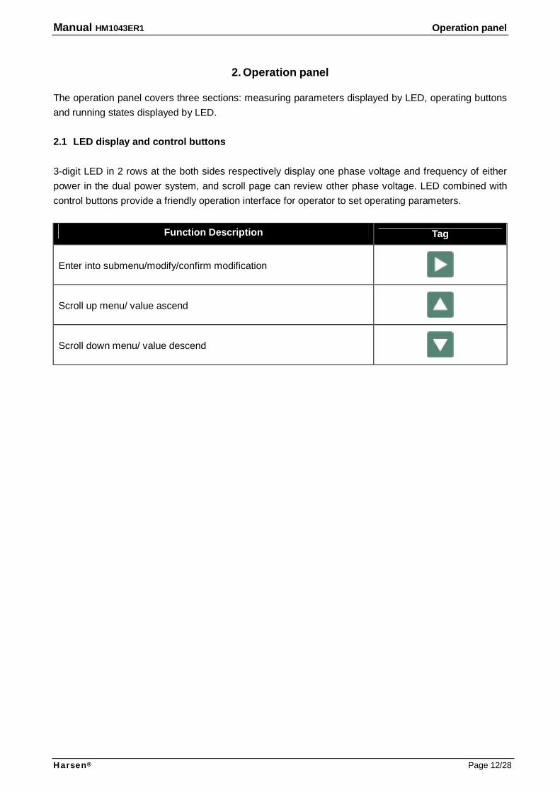
2. Operation panel The operation panel covers three sections: measuring parameters displayed by LED, operating buttons and running states displayed by LED. 2.1 LED display and control buttons 3-digit LED in 2 rows at the both sides respectively display one phase voltage and frequency of either power in the dual power system, and scroll page can review other phase voltage. LED combined with control buttons provide a friendly operation interface for operator to set operating parameters.
Function Description Tag
Enter into submenu/modify/confirm modification
Scroll up menu/ value ascend
Scroll down menu/ value descend
Manual HM1043ER1 Operation panel
Harsen® Page 13/28
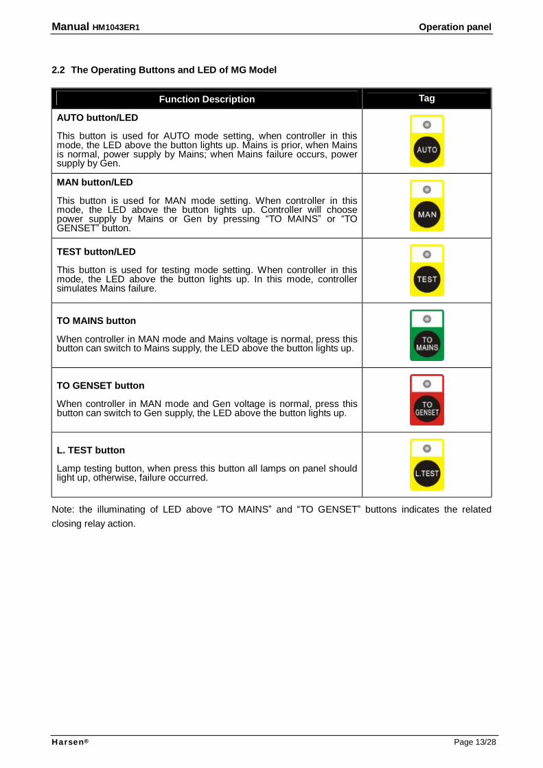
2.2 The Operating Buttons and LED of MG Model
Function Description Tag
AUTO button/LED This button is used for AUTO mode setting, when controller in this mode, the LED above the button lights up. Mains is prior, when Mains is normal, power supply by Mains; when Mains failure occurs, power supply by Gen.
MAN button/LED This button is used for MAN mode setting. When controller in this mode, the LED above the button lights up. Controller will choose power supply by Mains or Gen by pressing “TO MAINS” or “TO GENSET” button.
TEST button/LED This button is used for testing mode setting. When controller in this mode, the LED above the button lights up. In this mode, controller simulates Mains failure.
TO MAINS button When controller in MAN mode and Mains voltage is normal, press this button can switch to Mains supply, the LED above the button lights up.
TO GENSET button When controller in MAN mode and Gen voltage is normal, press this button can switch to Gen supply, the LED above the button lights up.
L. TEST button Lamp testing button, when press this button all lamps on panel should light up, otherwise, failure occurred.
Note: the illuminating of LED above “TO MAINS” and “TO GENSET” buttons indicates the related closing relay action.

Manual HM1043ER1 Operation panel
Harsen® Page 14/28
2.3 The Operating Buttons and LED of GG Model
Function Description Tag
GEN.1 button/ LED This button is used for 1# Gen. prior mode setting. LED above the button lights up when controller running in this mode. 1# Gen. is prior. When 1# Gen. is normal, power supply by 1# Gen.; if 1# Gen failure occurs, power supply by 2# Gen.
MAN button LED This button is used for MAN mode setting. LED above the button lights up when controller is running in this mode. Controller selects power supply by 1# Gen. or 2# Gen. by pressing “To GEN.1” or “To GEN.2”.
GEN.2 button/ LED This button is used for 2# Gen. prior mode setting. LED above the button lights up when running in this mode. 2# Gen. is prior. When 2# Gen. is normal, power supply by 2# Gen.; if 2# Gen failure occurs, power supply by 1# Gen.
TO GEN.1 button When controller in MAN mode and 1# Gen voltage is normal, press this button can switch to 1# Gen supply.
TO GEN.2 button When controller in MAN mode and 2# Gen voltage is normal, press this button can switch to 2# Gen supply.
L. TEST button Lamp testing button, when press this button all lamps on panel should light up, otherwise, failure occurred.
NOTE: the illuminating of LED above “TO GEN.1” and “TO GEN.2” buttons indicates the related closing relay action.
Manual HM1043ER1 Operation panel
Harsen® Page 15/28
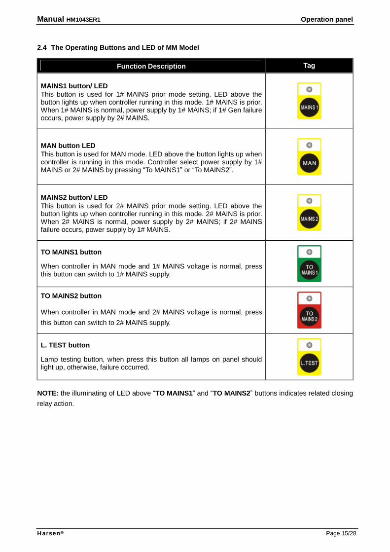
2.4 The Operating Buttons and LED of MM Model
Function Description Tag
MAINS1 button/ LED This button is used for 1# MAINS prior mode setting. LED above the button lights up when controller running in this mode. 1# MAINS is prior. When 1# MAINS is normal, power supply by 1# MAINS; if 1# Gen failure occurs, power supply by 2# MAINS.
MAN button LED This button is used for MAN mode. LED above the button lights up when controller is running in this mode. Controller select power supply by 1# MAINS or 2# MAINS by pressing “To MAINS1” or “To MAINS2”.
MAINS2 button/ LED This button is used for 2# MAINS prior mode setting. LED above the button lights up when controller running in this mode. 2# MAINS is prior. When 2# MAINS is normal, power supply by 2# MAINS; if 2# MAINS failure occurs, power supply by 1# MAINS.
TO MAINS1 button When controller in MAN mode and 1# MAINS voltage is normal, press this button can switch to 1# MAINS supply.
TO MAINS2 button When controller in MAN mode and 2# MAINS voltage is normal, press this button can switch to 2# MAINS supply.
L. TEST button Lamp testing button, when press this button all lamps on panel should light up, otherwise, failure occurred.
NOTE: the illuminating of LED above “TO MAINS1” and “TO MAINS2” buttons indicates related closing relay action.
Manual HM1043ER1 Installation Guide
Harsen® Page 16/28
3. Installation Guide 3.1 Panel Installation
The controller is fixed by 4 special screws. The shock-proof equipment must be installed, if the enclosure that installed on controller is directly installed on Genset body or other heavy vibrant device.
3.2 Please read drawing or above Typical Wiring Diagram for wiring connecting.
Manual HM1043ER1 Control and Operation Instruction
Harsen® Page 17/28
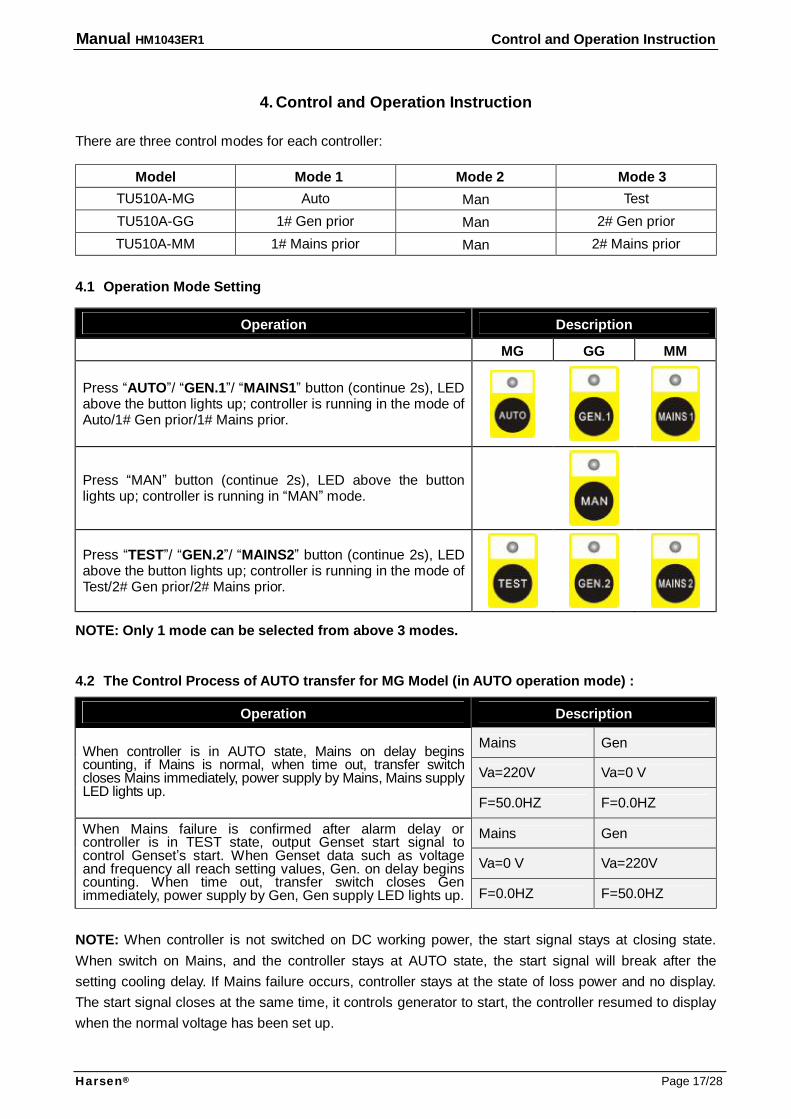
4. Control and Operation Instruction There are three control modes for each controller:
Model Mode 1 Mode 2 Mode 3 TU510A-MG Auto Man Test TU510A-GG 1# Gen prior Man 2# Gen prior TU510A-MM 1# Mains prior Man 2# Mains prior
4.1 Operation Mode Setting
Operation Description
MG GG MM
Press “AUTO”/ “GEN.1”/ “MAINS1” button (continue 2s), LED above the button lights up; controller is running in the mode of Auto/1# Gen prior/1# Mains prior.
Press “MAN” button (continue 2s), LED above the button lights up; controller is running in “MAN” mode.
Press “TEST”/ “GEN.2”/ “MAINS2” button (continue 2s), LED above the button lights up; controller is running in the mode of Test/2# Gen prior/2# Mains prior.
NOTE: Only 1 mode can be selected from above 3 modes. 4.2 The Control Process of AUTO transfer for MG Model (in AUTO operation mode) :
Operation Description
Mains Gen
Va=220V Va=0 V
When controller is in AUTO state, Mains on delay begins counting, if Mains is normal, when time out, transfer switch closes Mains immediately, power supply by Mains, Mains supply LED lights up.
F=50.0HZ F=0.0HZ
Mains Gen
Va=0 V Va=220V
When Mains failure is confirmed after alarm delay or controller is in TEST state, output Genset start signal to control Genset’s start. When Genset data such as voltage and frequency all reach setting values, Gen. on delay begins counting. When time out, transfer switch closes Gen immediately, power supply by Gen, Gen supply LED lights up. F=0.0HZ F=50.0HZ
NOTE: When controller is not switched on DC working power, the start signal stays at closing state. When switch on Mains, and the controller stays at AUTO state, the start signal will break after the setting cooling delay. If Mains failure occurs, controller stays at the state of loss power and no display. The start signal closes at the same time, it controls generator to start, the controller resumed to display when the normal voltage has been set up.
Manual HM1043ER1 Control and Operation Instruction
Harsen® Page 18/28
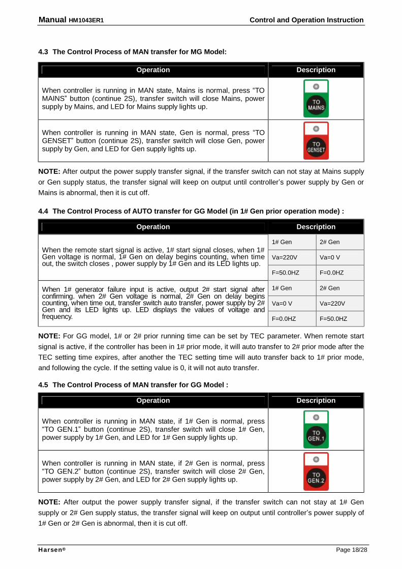
4.3 The Control Process of MAN transfer for MG Model:
Operation Description
When controller is running in MAN state, Mains is normal, press “TO MAINS” button (continue 2S), transfer switch will close Mains, power supply by Mains, and LED for Mains supply lights up.
When controller is running in MAN state, Gen is normal, press “TO GENSET” button (continue 2S), transfer switch will close Gen, power supply by Gen, and LED for Gen supply lights up.
NOTE: After output the power supply transfer signal, if the transfer switch can not stay at Mains supply or Gen supply status, the transfer signal will keep on output until controller’s power supply by Gen or Mains is abnormal, then it is cut off. 4.4 The Control Process of AUTO transfer for GG Model (in 1# Gen prior operation mode) :
Operation Description
1# Gen 2# Gen
Va=220V Va=0 V When the remote start signal is active, 1# start signal closes, when 1# Gen voltage is normal, 1# Gen on delay begins counting, when time out, the switch closes , power supply by 1# Gen and its LED lights up.
F=50.0HZ F=0.0HZ
1# Gen 2# Gen
Va=0 V Va=220V
When 1# generator failure input is active, output 2# start signal after confirming. when 2# Gen voltage is normal, 2# Gen on delay begins counting, when time out, transfer switch auto transfer, power supply by 2# Gen and its LED lights up. LED displays the values of voltage and frequency. F=0.0HZ F=50.0HZ
NOTE: For GG model, 1# or 2# prior running time can be set by TEC parameter. When remote start signal is active, if the controller has been in 1# prior mode, it will auto transfer to 2# prior mode after the TEC setting time expires, after another the TEC setting time will auto transfer back to 1# prior mode, and following the cycle. If the setting value is 0, it will not auto transfer. 4.5 The Control Process of MAN transfer for GG Model :
Operation Description
When controller is running in MAN state, if 1# Gen is normal, press “TO GEN.1” button (continue 2S), transfer switch will close 1# Gen, power supply by 1# Gen, and LED for 1# Gen supply lights up.
When controller is running in MAN state, if 2# Gen is normal, press “TO GEN.2” button (continue 2S), transfer switch will close 2# Gen, power supply by 2# Gen, and LED for 2# Gen supply lights up.
NOTE: After output the power supply transfer signal, if the transfer switch can not stay at 1# Gen supply or 2# Gen supply status, the transfer signal will keep on output until controller’s power supply of 1# Gen or 2# Gen is abnormal, then it is cut off.
Manual HM1043ER1 Control and Operation Instruction
Harsen® Page 19/28
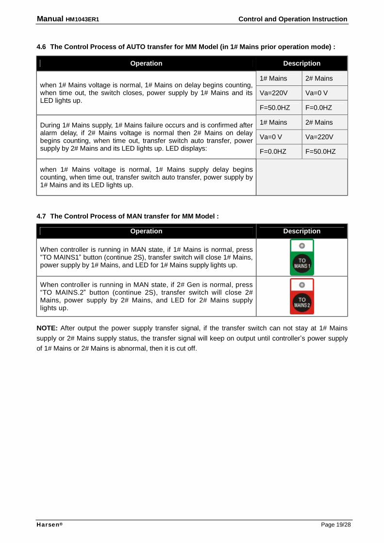
4.6 The Control Process of AUTO transfer for MM Model (in 1# Mains prior operation mode) :
Operation Description
1# Mains 2# Mains
Va=220V Va=0 V when 1# Mains voltage is normal, 1# Mains on delay begins counting, when time out, the switch closes, power supply by 1# Mains and its LED lights up.
F=50.0HZ F=0.0HZ
1# Mains 2# Mains
Va=0 V Va=220V
During 1# Mains supply, 1# Mains failure occurs and is confirmed after alarm delay, if 2# Mains voltage is normal then 2# Mains on delay begins counting, when time out, transfer switch auto transfer, power supply by 2# Mains and its LED lights up. LED displays: F=0.0HZ F=50.0HZ
when 1# Mains voltage is normal, 1# Mains supply delay begins counting, when time out, transfer switch auto transfer, power supply by 1# Mains and its LED lights up.
4.7 The Control Process of MAN transfer for MM Model :
Operation Description
When controller is running in MAN state, if 1# Mains is normal, press “TO MAINS1” button (continue 2S), transfer switch will close 1# Mains, power supply by 1# Mains, and LED for 1# Mains supply lights up.
When controller is running in MAN state, if 2# Gen is normal, press “TO MAINS.2” button (continue 2S), transfer switch will close 2# Mains, power supply by 2# Mains, and LED for 2# Mains supply lights up.
NOTE: After output the power supply transfer signal, if the transfer switch can not stay at 1# Mains supply or 2# Mains supply status, the transfer signal will keep on output until controller’s power supply of 1# Mains or 2# Mains is abnormal, then it is cut off.
Manual HM1043ER1 Measure and Display Data
Harsen® Page 20/28
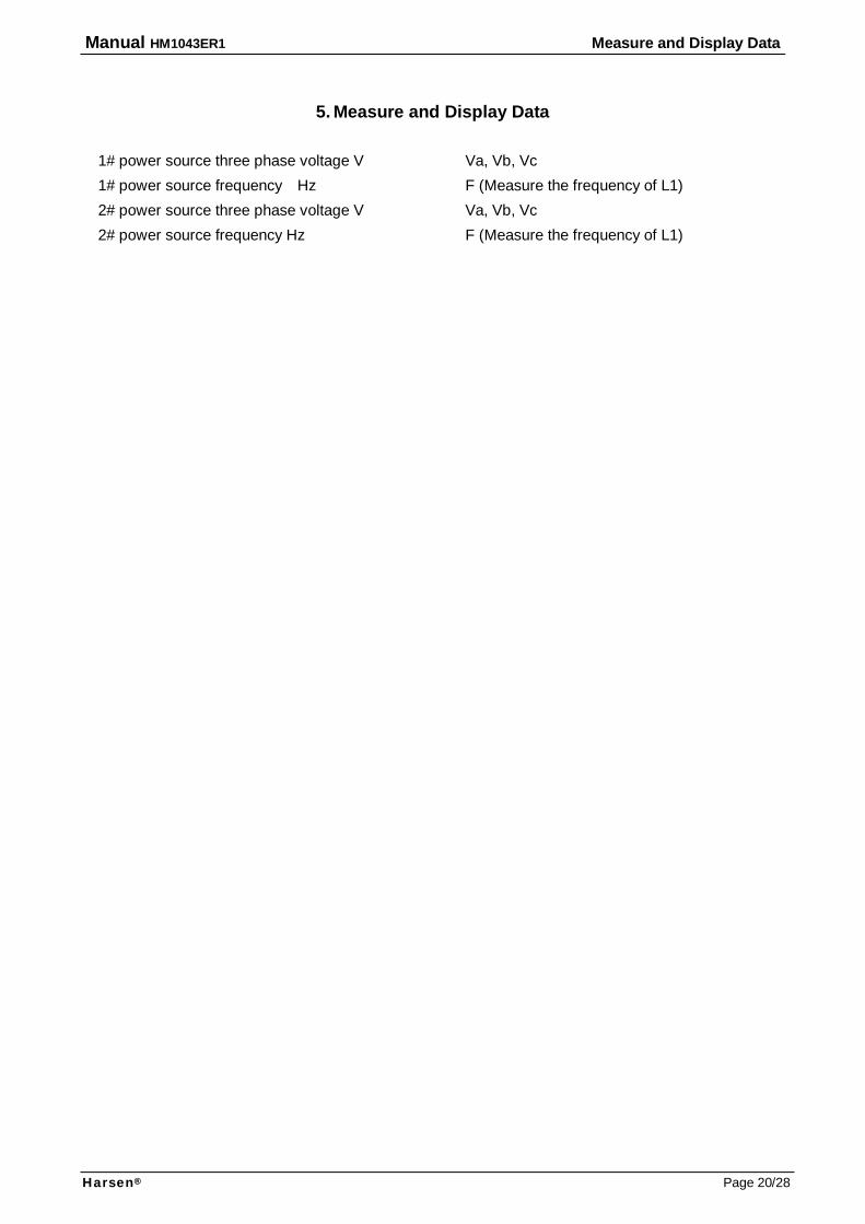
5. Measure and Display Data
1# power source three phase voltage V Va, Vb, Vc 1# power source frequency Hz F (Measure the frequency of L1) 2# power source three phase voltage V Va, Vb, Vc 2# power source frequency Hz F (Measure the frequency of L1)
Manual HM1043ER1 Alarm
Harsen® Page 21/28
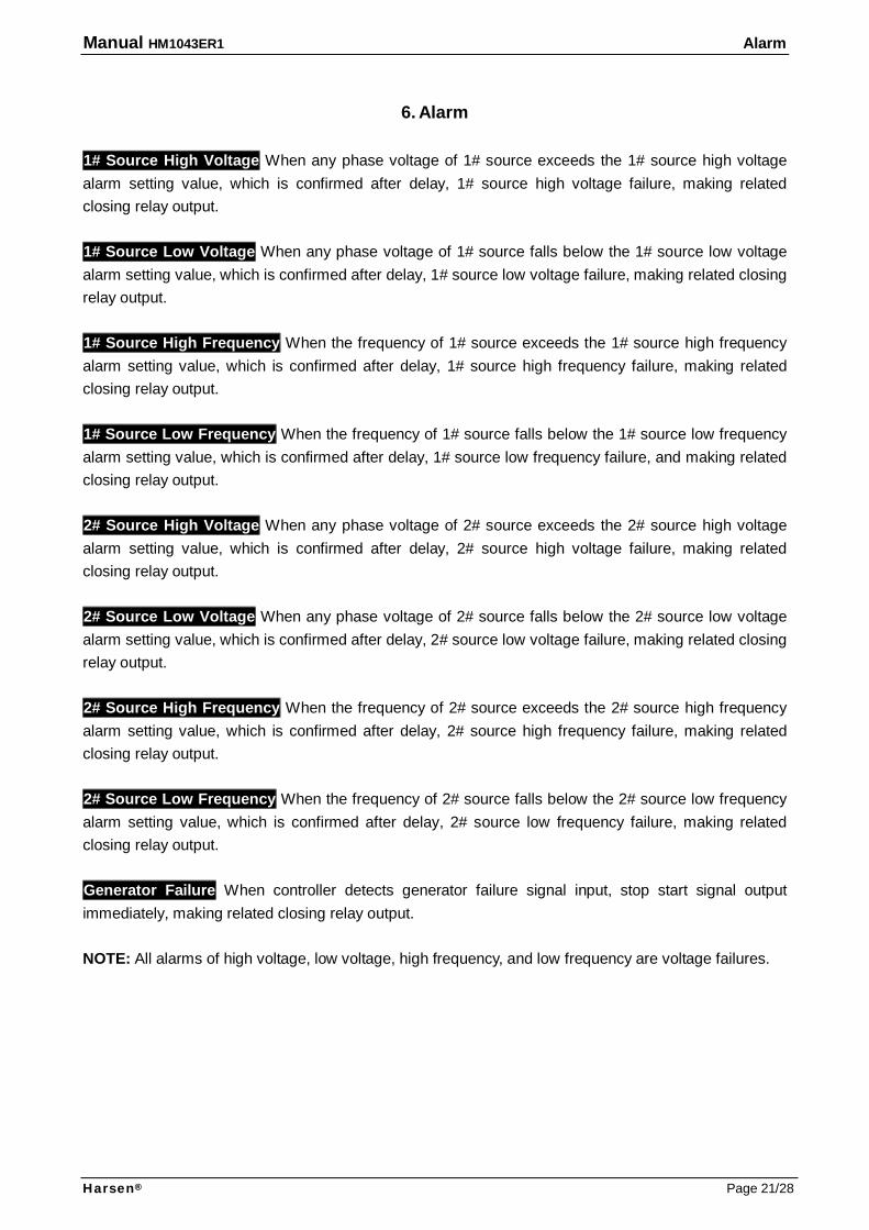
6. Alarm 1# Source High Voltage When any phase voltage of 1# source exceeds the 1# source high voltage alarm setting value, which is confirmed after delay, 1# source high voltage failure, making related closing relay output. 1# Source Low Voltage When any phase voltage of 1# source falls below the 1# source low voltage alarm setting value, which is confirmed after delay, 1# source low voltage failure, making related closing relay output. 1# Source High Frequency When the frequency of 1# source exceeds the 1# source high frequency alarm setting value, which is confirmed after delay, 1# source high frequency failure, making related closing relay output. 1# Source Low Frequency When the frequency of 1# source falls below the 1# source low frequency alarm setting value, which is confirmed after delay, 1# source low frequency failure, and making related closing relay output. 2# Source High Voltage When any phase voltage of 2# source exceeds the 2# source high voltage alarm setting value, which is confirmed after delay, 2# source high voltage failure, making related closing relay output. 2# Source Low Voltage When any phase voltage of 2# source falls below the 2# source low voltage alarm setting value, which is confirmed after delay, 2# source low voltage failure, making related closing relay output. 2# Source High Frequency When the frequency of 2# source exceeds the 2# source high frequency alarm setting value, which is confirmed after delay, 2# source high frequency failure, making related closing relay output. 2# Source Low Frequency When the frequency of 2# source falls below the 2# source low frequency alarm setting value, which is confirmed after delay, 2# source low frequency failure, making related closing relay output. Generator Failure When controller detects generator failure signal input, stop start signal output immediately, making related closing relay output. NOTE: All alarms of high voltage, low voltage, high frequency, and low frequency are voltage failures.
Manual HM1043ER1 Parameters Setting
Harsen® Page 22/28
7. Parameters Setting
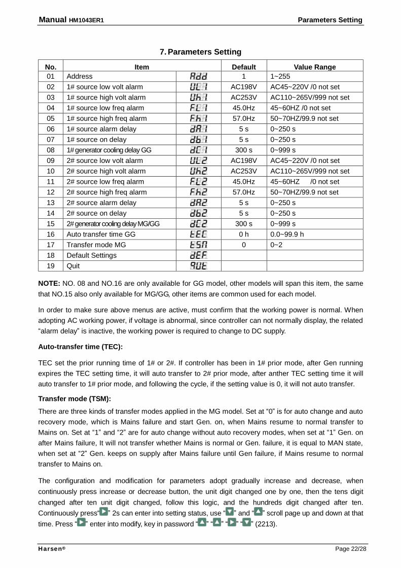
No. Item Default Value Range 01 Address 1 1~255 02 1# source low volt alarm AC198V AC45~220V /0 not set 03 1# source high volt alarm AC253V AC110~265V/999 not set 04 1# source low freq alarm 45.0Hz 45~60HZ /0 not set 05 1# source high freq alarm 57.0Hz 50~70HZ/99.9 not set 06 1# source alarm delay 5 s 0~250 s 07 1# source on delay 5 s 0~250 s 08 1# generator cooling delay GG 300 s 0~999 s 09 2# source low volt alarm AC198V AC45~220V /0 not set 10 2# source high volt alarm AC253V AC110~265V/999 not set 11 2# source low freq alarm 45.0Hz 45~60HZ /0 not set 12 2# source high freq alarm 57.0Hz 50~70HZ/99.9 not set 13 2# source alarm delay 5 s 0~250 s 14 2# source on delay 5 s 0~250 s 15 2# generator cooling delay MG/GG 300 s 0~999 s 16 Auto transfer time GG 0 h 0.0~99.9 h 17 Transfer mode MG 0 0~2 18 Default Settings 19 Quit
NOTE: NO. 08 and NO.16 are only available for GG model, other models will span this item, the same that NO.15 also only available for MG/GG, other items are common used for each model. In order to make sure above menus are active, must confirm that the working power is normal. When adopting AC working power, if voltage is abnormal, since controller can not normally display, the related “alarm delay” is inactive, the working power is required to change to DC supply. Auto-transfer time (TEC): TEC set the prior running time of 1# or 2#. If controller has been in 1# prior mode, after Gen running expires the TEC setting time, it will auto transfer to 2# prior mode, after anther TEC setting time it will auto transfer to 1# prior mode, and following the cycle, if the setting value is 0, it will not auto transfer. Transfer mode (TSM): There are three kinds of transfer modes applied in the MG model. Set at “0” is for auto change and auto recovery mode, which is Mains failure and start Gen. on, when Mains resume to normal transfer to Mains on. Set at “1” and “2” are for auto change without auto recovery modes, when set at “1” Gen. on after Mains failure, It will not transfer whether Mains is normal or Gen. failure, it is equal to MAN state, when set at “2” Gen. keeps on supply after Mains failure until Gen failure, if Mains resume to normal transfer to Mains on. The configuration and modification for parameters adopt gradually increase and decrease, when continuously press increase or decrease button, the unit digit changed one by one, then the tens digit changed after ten unit digit changed, follow this logic, and the hundreds digit changed after ten. Continuously press“ ” 2s can enter into setting status, use “ ” and “ ” scroll page up and down at that time. Press “ ” enter into modify, key in password “ ” “ ” “ ” “ ” (2213).
Manual HM1043ER1 Parameters Setting
Harsen® Page 23/28
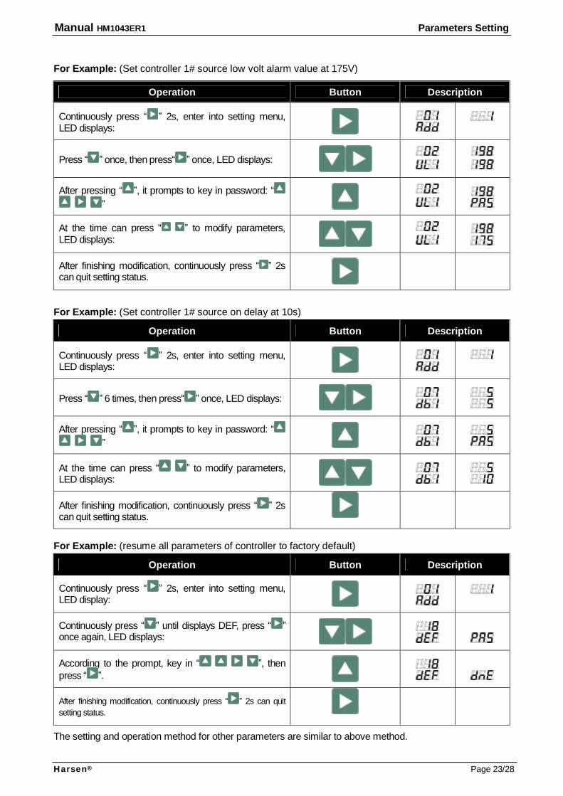
For Example: (Set controller 1# source low volt alarm value at 175V)
Operation Button Description
Continuously press “ ” 2s, enter into setting menu, LED displays:
Press “ ” once, then press“ ” once, LED displays:
After pressing “ ”, it prompts to key in password: “ ”
At the time can press “ ” to modify parameters, LED displays:
After finishing modification, continuously press “ ” 2s can quit setting status.
For Example: (Set controller 1# source on delay at 10s)
Operation Button Description
Continuously press “ ” 2s, enter into setting menu, LED displays:
Press “ ” 6 times, then press“ ” once, LED displays:
After pressing “ ”, it prompts to key in password: “ ”
At the time can press “ ” to modify parameters, LED displays:
After finishing modification, continuously press “ ” 2s can quit setting status.
For Example: (resume all parameters of controller to factory default)
Operation Button Description
Continuously press “ ” 2s, enter into setting menu, LED display:
Continuously press “ ” until displays DEF, press “ ” once again, LED displays:
According to the prompt, key in “ ”, then press “ ”.
After finishing modification, continuously press “ ” 2s can quit setting status.
The setting and operation method for other parameters are similar to above method.
Manual HM1043ER1 Communication Function
Harsen® Page 24/28
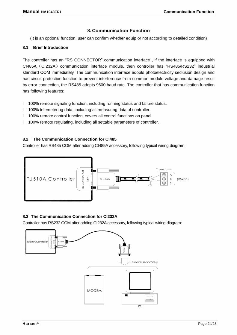
8. Communication Function (It is an optional function, user can confirm whether equip or not according to detailed condition)
8.1 Brief Introduction
The controller has an “RS CONNECTOR” communication interface , if the interface is equipped with CI485A(CI232A)communication interface module, then controller has “RS485/RS232” industrial standard COM immediately. The communication interface adopts photoelectricity seclusion design and has circuit protection function to prevent interference from common module voltage and damage result by error connection, the RS485 adopts 9600 baud rate. The controller that has communication function has following features: l 100% remote signaling function, including running status and failure status. l 100% telemetering data, including all measuring data of controller. l 100% remote control function, covers all control functions on panel. l 100% remote regulating, including all settable parameters of controller.
8.2 The Communication Connection for CI485 Controller has RS485 COM after adding CI485A accessory, following typical wiring diagram:
8.3 The Communication Connection for CI232A Controller has RS232 COM after adding CI232A accessory, following typical wiring diagram:
RS C
ON
NEC
TOR
CI232A
(DB9
)
MODEM
PC
CI2
32A
Can link separately
TU510A Controller
RS C
ON
NEC
TOR
C I4 8 5 A
(DB9
)
A
Tra n sfo rm
SB ( R S 4 8 5)TU 5 1 0 A C o n tro lle r

Manual HM1043ER1 Communication Function
Harsen® Page 25/28
8.4 The Communication Connection for Multi Controllers The communication interface offers user a route: from which you can get more information that can not obtain from panel, the matching software can display all measured parameters and status information, and can set all parameters. The controller that has RS485 COM allows 1 communication bus can mostly connect 247 same series of controllers by wiring connection mode. Each device has only one ID NO., and only can be connected to PC or MODEM by matching with another RS485/RS232 shifter in that time. Following typical wiring diagram:
NOTE: Communication cable used high quality shielded twisted-pair cable, and its amount length must not exceed 1000m. The anode and cathode of RS485 in each controller must be correctly connected, and the cable shield only can be grounded at one side.
(DB9)
RS CONNECTOR
CI4
85A
R to
risis
tanc
e
A B S
PC
RS CONNECTOR
(DB9)
CI4
85A
RS CONNECTOR
(DB9)
CI4
85A
MO
DEM
A Tra
nsfo
rmer
RS48
5/23
2
B S
can
conn
ect s
eper
ate
ly
A B SBA S
TU51
0A C
ontro
ller
TU51
0A C
ontro
ller
TU51
0A C
ontro
ller
Manual HM1043ER1 Communication Function
Harsen® Page 26/28
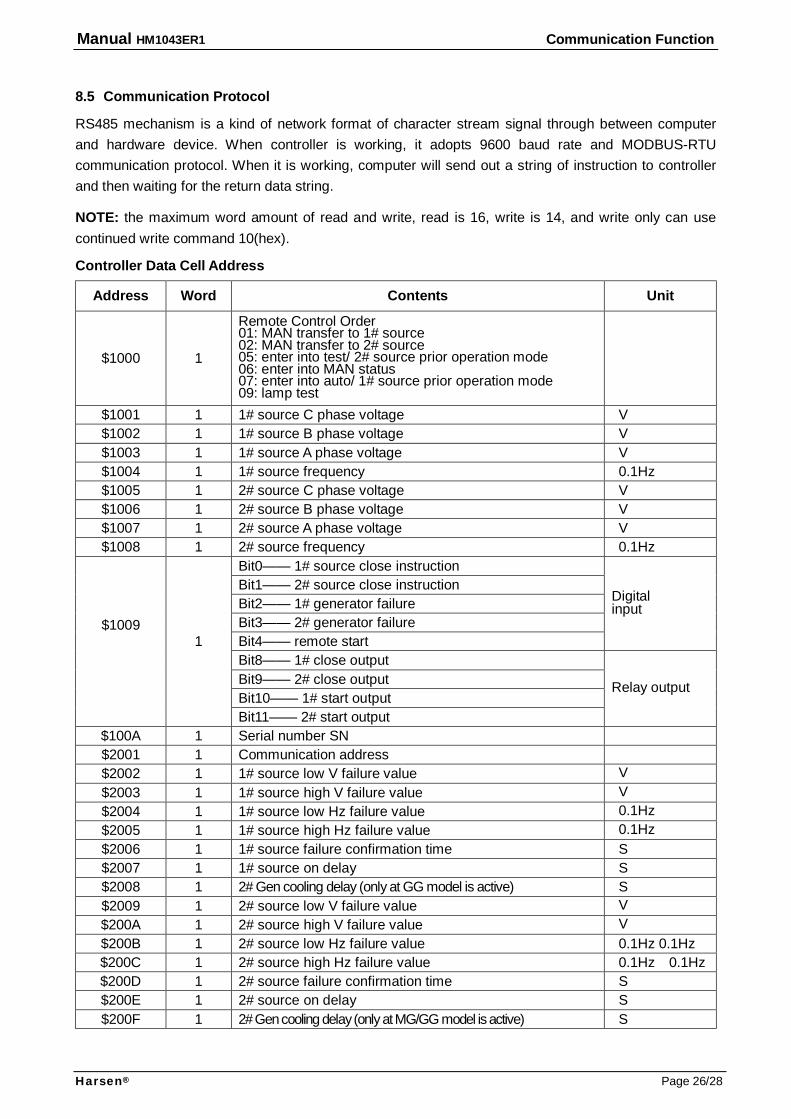
8.5 Communication Protocol RS485 mechanism is a kind of network format of character stream signal through between computer and hardware device. When controller is working, it adopts 9600 baud rate and MODBUS-RTU communication protocol. When it is working, computer will send out a string of instruction to controller and then waiting for the return data string. NOTE: the maximum word amount of read and write, read is 16, write is 14, and write only can use continued write command 10(hex). Controller Data Cell Address
Address Word Contents Unit
$1000 1
Remote Control Order 01: MAN transfer to 1# source 02: MAN transfer to 2# source 05: enter into test/ 2# source prior operation mode 06: enter into MAN status 07: enter into auto/ 1# source prior operation mode 09: lamp test
$1001 1 1# source C phase voltage V $1002 1 1# source B phase voltage V $1003 1 1# source A phase voltage V $1004 1 1# source frequency 0.1Hz $1005 1 2# source C phase voltage V $1006 1 2# source B phase voltage V $1007 1 2# source A phase voltage V $1008 1 2# source frequency 0.1Hz
Bit0—— 1# source close instruction Bit1—— 2# source close instruction Bit2—— 1# generator failure Bit3—— 2# generator failure Bit4—— remote start
Digital input
Bit8—— 1# close output Bit9—— 2# close output Bit10—— 1# start output
$1009
1
Bit11—— 2# start output
Relay output
$100A 1 Serial number SN $2001 1 Communication address $2002 1 1# source low V failure value V $2003 1 1# source high V failure value V $2004 1 1# source low Hz failure value 0.1Hz $2005 1 1# source high Hz failure value 0.1Hz $2006 1 1# source failure confirmation time S $2007 1 1# source on delay S $2008 1 2# Gen cooling delay (only at GG model is active) S $2009 1 2# source low V failure value V $200A 1 2# source high V failure value V $200B 1 2# source low Hz failure value 0.1Hz 0.1Hz $200C 1 2# source high Hz failure value 0.1Hz 0.1Hz $200D 1 2# source failure confirmation time S $200E 1 2# source on delay S $200F 1 2# Gen cooling delay (only at MG/GG model is active) S
Manual HM1043ER1 Technical Parameters
Harsen® Page 27/28
9. Technical Parameters Working voltage: AC85-265V (The internal power supply is from the A-phase of the dual power,
dispenses with additional power) or 12V/24V (8-35VDC continuous) controller defaults AC supply (except GG).
Max power consumption: <3W Measure AC voltage input: 75-300V (ph-N) true RMS AC measure accuracy: 0.5 level The measure range of frequency: 45-65Hz Using ambient temperature: -20 to 50℃ Storage ambient temperature: -40 to 80℃ Switch control relay output: 10A/250VAC Aux. relay output: 5A/250VAC/30VDC
Manual HM1043ER1 Troubleshooting
Harsen® Page 28/28
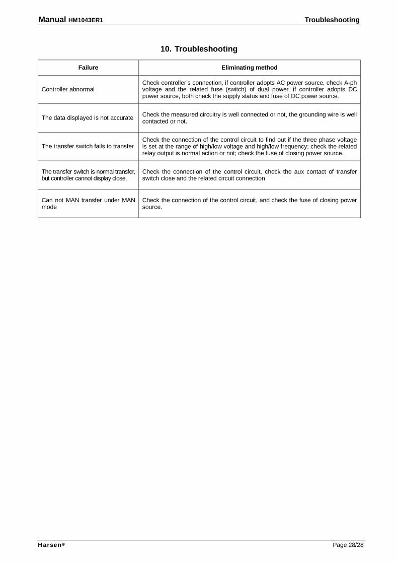
10. Troubleshooting
Failure Eliminating method
Controller abnormal Check controller’s connection, if controller adopts AC power source, check A-ph voltage and the related fuse (switch) of dual power, if controller adopts DC power source, both check the supply status and fuse of DC power source.
The data displayed is not accurate Check the measured circuitry is well connected or not, the grounding wire is well contacted or not.
The transfer switch fails to transfer Check the connection of the control circuit to find out if the three phase voltage is set at the range of high/low voltage and high/low frequency; check the related relay output is normal action or not; check the fuse of closing power source.
The transfer switch is normal transfer, but controller cannot display close.
Check the connection of the control circuit, check the aux contact of transfer switch close and the related circuit connection
Can not MAN transfer under MAN mode
Check the connection of the control circuit, and check the fuse of closing power source.

Service Hotline
4008883388
More technical support, Please browse our website: www.jnhharsen.com
www.harsen.com.cn