Deliverable 5.1 Installation and permitting procedure · CEI 0 – 2:” Guide for the definition...
30
“Demonstration Project for Power Supply to Telecom Stations through FC technology” Deliverable 5.1 Installation and permitting procedure Version 4.0 Report submission date: 20140114 Dissemination level: PU Work Package 5 - Installation Work Package Leader: Ericsson Contributors: Ericsson This project is co-financed by funds from the European Commission under Fuel Cell and Hydrogen Joint Undertaking Application Area SP1-JTI-FCH.4: Early Markets Topic: SP1-JTI-FCH.2010.4.2 Demonstration of industrial application readiness of fuel cell generators for power supply to off-grid stations, including the hydrogen supply solution FCH-JU-2010-1 Grant Agreement Number 278921. Dissemination Level PU Public x PP Restricted to other program participants (including the Commission Services) RE Restricted to a group specified by the consortium (including the Commission Services) CO Confidential, only for members of the consortium (including the Commission Services) Contact Details:
-
Upload
duongxuyen -
Category
Documents
-
view
222 -
download
0
Transcript of Deliverable 5.1 Installation and permitting procedure · CEI 0 – 2:” Guide for the definition...

“Demonstration Project for Power Supply to Telecom Stations
through FC technology”
Deliverable 5.1Installation and permitting procedure
Version 4.0Report submission date: 20140114Dissemination level: PUWork Package 5 - InstallationWork Package Leader: EricssonContributors: Ericsson
This project is co-financed by funds from the European Commission underFuel Cell and Hydrogen Joint Undertaking
Application Area SP1-JTI-FCH.4: Early Markets
Topic: SP1-JTI-FCH.2010.4.2 Demonstration of industrial application readiness of fuelcell generators for power supply to off-grid stations, including the hydrogen supply
solution
FCH-JU-2010-1 Grant Agreement Number 278921.
Dissemination Level
PU Public x
PP Restricted to other program participants (including the Commission Services)
RE Restricted to a group specified bythe consortium (including the Commission Services)
CO Confidential, only for members of the consortium (including the Commission Services)
Contact Details:

“Demonstration Project for
Power Supply to Telecom Stations
through FC technology”
Coordinator: Giancarlo Tomarchio - ERICSSON Telecomunicazioni S.p.A
Document prepared and contributed by
[Giovanni Cassano,Ericsson] e-mail: [email protected]
[Mario Savino,Ericsson] e-mail: [email protected]
[Marco Filonzi, Ericsson] e-mail: [email protected]
[Piero Montanucci, Ericsson] e-mail: [email protected]
[Roberto Salvi, Ericsson] e-mail: [email protected]
Document Log:
Version Date Summary of changes Author
1.0 2012/05/16 Draft Giovanni Cassano
2.0 2012/05/25 First version Giovanni Cassano
3.0 2013/03/29Small changes – ready for
submissionMario Savino
4.0 2014/01/14Review according to local
authorization Marco Filonzi
FCpoweredRBS D 5.1 2 of 30 Publicity Information(Public)

“Demonstration Project for
Power Supply to Telecom Stations
through FC technology”
Table of Contents
Table of Contents................................................................................................................... 3
1. Introduction...................................................................................................................... 4
2. Operative Process............................................................................................................ 5
3. System Description – General Block Scheme..........................................................6
4. RBS Configurations provided for the 18 test..........................................................8
5. Authorizations of Authorities for Permit and Installation..............................11
5.1 Normative references.............................................................................................................11
5.2 Authorizations for building permit..........................................................................................13
6. Hazards associated with fuel cell installation and operation.........................16
7. Installation of equipment and Layout provided.................................................18
7.1 Feasibility Study......................................................................................................................18
7.2 Photovoltaic roof....................................................................................................................19
7.3 Supply System Powered by Hydrogen.....................................................................................21
7.4 Site layout...............................................................................................................................24
8. Logistics............................................................................................................................ 26
9. ATEX Hazardous and Risk Evaluation....................................................................27
10. Appendix 1- Recommendations...........................................................................28
11. Appendix 2- Emergency Planning........................................................................30
12. Appendix 3- Evaluation Methodology of Risk Assessment..........................31
FCpoweredRBS D 5.1 3 of 30 Publicity Information(Public)

“Demonstration Project for
Power Supply to Telecom Stations
through FC technology”
1. IntroductionThe system architecture developed for the present project is composed by differentenergy sources in order to power the system just through renewable energy. Thesolution is characterized by a Photovoltaic System and a Fuel Cell System poweringRadio Base Stations (RBS). In order to produce the minimum amount of energy requiredfrom RBS, its maximum consumption has been estimated.
The goal of the present document is to describe:
Overview of the operative process to implement the solution
System description-General Block scheme
RBS Configurations provided for 18 testing activities, with related installationschemes
indications about Authorities authorizations to obtain installation and buildingpermit
hazards associated with fuel cell installation and operation
The project will involve a number of 18 sites and all sites will be located in Italy due toTelCo Operators interest in environmental issues. The Operators have mainly identifiedRBS sites situated on raw-land zones. According to prerequisites, the sites will be placedin South – Central area, with a good exposition toward south (to guarantee maximumsolar exposition to PV panels). In this way it will be possible to evaluate systemperformance at different latitude.
The information explained in the following paragraphs are not exhaustive due to thevariability of site characteristics and some difference in local application of existingregulations mentioned above.
2. Operative Process
FCpoweredRBS D 5.1 4 of 30 Publicity Information(Public)
“Demonstration Project for
Power Supply to Telecom Stations
through FC technology”
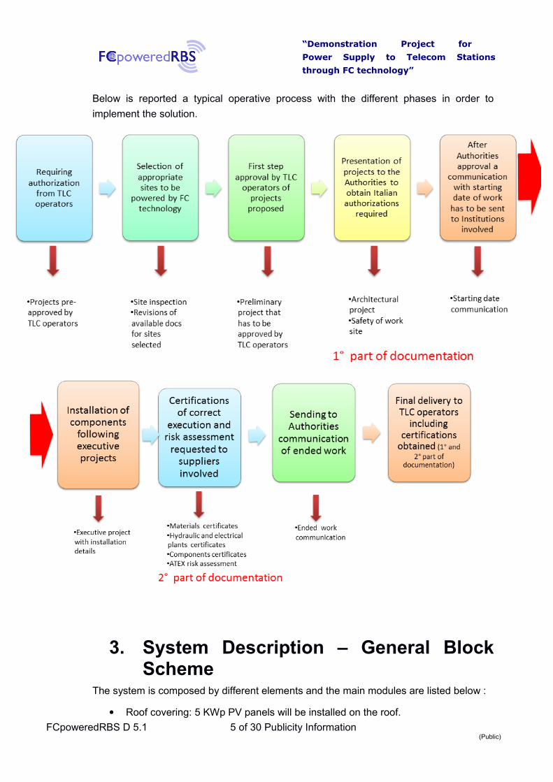
Below is reported a typical operative process with the different phases in order to
implement the solution.
3. System Description – General BlockScheme
The system is composed by different elements and the main modules are listed below :
Roof covering: 5 KWp PV panels will be installed on the roof.
FCpoweredRBS D 5.1 5 of 30 Publicity Information(Public)

“Demonstration Project for
Power Supply to Telecom Stations
through FC technology”
Energy Box System, which is assembled in outdoor rack and it is composed byDC/DC unit converter, connection and sectioning panel, DC counter remote-readable and sealable accounting for energy produced by PV panels of netlosses.
Fuel cells.
Battery Charger, that works as automatic charging of the batteries.
Battery Package.
Control Board, which is a system able to monitor and control the whole solution.In the control board it is possible to implement algorithm for defining working flowof process. It collects all signals such as alarms, measurements, etc. and areimplemented Analog and Digital Input/Output, RS485 Interface, and GPRScommunication.
Electrolyser, in configurations where it is expected.
Reserve of hydrogen or methanol, depending on the configurations.
Figure 1 contains the main blocks of the system, showing all components integrated intothe solution suggested:
Figure 1: System Architecture showing the main components.
The system consists of a power bus, called “48 V iDC BUS”, whose range of operating voltage is at 50%DoD and 56 Vdc.
FCpoweredRBS D 5.1 6 of 30 Publicity Information(Public)

“Demonstration Project for
Power Supply to Telecom Stations
through FC technology”
On “48 V DC BUS”, converges energy from three possible power sources, which are listed in order of priority:
1° Photovoltaic Energy System, 2° Battery Package, 3° Fuel Cell System.
These sources inject energy into the load (RBS) in exclusive or combined ways,
depending on the availability of individual sources, which are managed in strict order of
priority.
4. RBS Configurations provided for the 18test
Several configurations have been planned considering components available from
partners that provide fuel cells, electrolysers and their alimentation besides TelCo sites
needs.
Every site will host all components listed below according to configuration installed:
Roof covering to support the PV panels
Rack containing Energy Box
Rack containing the fuel cells and the batteries
MPPT charger
Electrolyser
Control Board
Space for hydrogen and methanol storing according to configurations.
All different configurations are listed below, included number of sites where they will be
installed. The configuration named “Type B” will not be realized since the system doesn’t
allow to store an hydrogen amount produced by RES higher than requested. According
DoW specifications explained in the section “Work Plan Table 3” referred to WP2, just
the “Type A” and “Type “C” can be implemented as displayed below:
Type A equipped as follow:
FCpoweredRBS D 5.1 7 of 30 Publicity Information(Public)

“Demonstration Project for
Power Supply to Telecom Stations
through FC technology”
A1
o 3 Fuel Cells @ 1.7 kW “Dantherm”,
o H2 stored in 200 bar pressure tanks,
o Energy Box,
o 5 kW PV Panels.
A2
o 2 Fuel Cells @ 2.5 or 5 kW “IdaTechElectraGen™”, operating with H2
produced by a steam reforming system of methanol-water (named“HydroPlus”), stored in a specific tank allocated under the fuel cell box fora capacity of 225 lt,
o Energy Box,
o 5 kW PV Panels.
Type C equipped as followed:
C1
o 3 Fuel Cells @ 1.7 kW “Dantherm”,
o H2 stored in 200 bar pressure tanks,
o “Green Hydrogen Electrolyser” to produce H2 locally stored in a 30 barpressure buffer tank,
o Energy Box,
o 5 kW PV Panels.
C2
o 2 Fuel Cells @ 1.1 kW “MES”,
o H2 stored in 200 bar pressure tanks,
o “Voltiana H2 Nitidor Electrolyser” to produce H2 locally stored in a 30 barpressure buffer tank,
o Energy Box,
o 5 kW PV Panels.
The criteria of system installed will be determine by each TelCo operator involvedin the project. Every operator will chose one or more configurations in order to run theirsites by appropriate alimentation to guarantee correct and continuous operation.
Figure 2 displays the functional electrical layout of all equipment involved in thesolution adopted, reporting the main components and how they are integrated in thesystem. The solutions are further explained in the report dedicated where also specificsof every different fuel cell electrical connections are described.
FCpoweredRBS D 5.1 8 of 30 Publicity Information(Public)

“Demonstration Project for
Power Supply to Telecom Stations
through FC technology”
a)
b)
Figure 2: Electrical layout with integration of functionalities related to every system component in a)and 3D view in b).
FCpoweredRBS D 5.1 9 of 30 Publicity Information(Public)

“Demonstration Project for
Power Supply to Telecom Stations
through FC technology”
5. Authorizations of Authorities for Permitand Installation
5.1 Normative references
In this section are summarized the regulations related to the authorizations for askingpermissions to build and warrant all necessary works for a complete installation. Twokinds of regulations have to be taken into account: the government and county laws thatare applied over the entire Italian territory. The first ones are common all around thestate territory while county regulations are different between all Regions and differentlocal processes must be tailored and charted.
The list reported below displays the main laws that have to be followed to obtain allgovernment compulsory permissions:
Decree of President Republic June 6th, 2001, n. 380 “Consolidated text of lawsand regulations on construction” (D.P.R. 380/2001).
Decree of Economic Development Ministry January 22nd, 2008, n. 37:”Regulations concerning the implementation of article 11–quaterdecies,paragraph 13, letter a) of the law of December 22nd, 2005, addressing thereorganization about dispositions concerning plant installation activities insidebuildings” (D.M. 37/08).
Decree of Republic’s President August 1st, 2011, n. 151: ”Regulations for thesimplification of procedures relating to fire prevention, under Article 49,paragraph 4-quarter, of the Decree law May 31st, 2010, n. 78, amended by law ofJuly 30th, 2010, n. 122 ” (D.Lgs. 151/2011).
Legislative Decree April 9th, 2008, n.81: “Occupational health and safetydistinctive test” (D.Lgs. 81/08).
Legislative Decree June 12th, 2003, n. 233: “Implementation of the 1999/92/CEDirective on minimum requirements for improving the protection of safety andhealth of workers at risk from explosive atmospheres” (D.Lgs. 233/03).
Law December 6th, 1971, n. 1083 “Regulation for safe use of combustible gas”(Legge n° 1083/71).
The following list reports technical regulation regarding: photovoltaic generators,requirements for the project, construction and testing of wiring for implants. In particular,it refers to the photovoltaic generators and to the production systems from fuel cellshydrogen powered, included explosive atmosphere:
CEI 0 – 2:” Guide for the definition of the project documentation for wirings”.
CEI 64-8 Regulation: “Wirings users rated voltage not exceeding 1000 V AC and1500 V DC”.
CEI 20-91 “Electrical cables with elastomeric insulated and sheath halogen-freeflame retardant with rated voltage not exceeding 1000 V AC and 1500 V DC forPV system applications”.
FCpoweredRBS D 5.1 10 of 30 Publicity Information(Public)

“Demonstration Project for
Power Supply to Telecom Stations
through FC technology”
CEI EN 60529 (CEI 70-1) Regulation: “Degrees of protection provided byenclosures (IP code)”.
CEI EN 62305 Regulation (CEI 81-10): “Protection against lightning”.
CEI 813 Regulation: “Mean values of the number of lightning to the ground forone year and for Km2”.
CEI 20-19 Regulation: ”Isolated cables with rubber and with rated voltage notexceeding to 450/750 V”.
CEI 20-21 Regulation: “Electrical cables capacity under permanent regime”.
CEI EN 60079-10 (CEI 31-30) Regulation: “Electrical apparatus for explosiveatmospheres due to the presence of gas – 10th Part: Classification of hazardousareas”.
CEI 31-35: “Electrical apparatus for explosive atmospheres due to the presenceof gas – Guide for the application of the CEI EN 60079-10 Regulation (CEI 31-30) – Classification of areas at risk of explosion due to the presence of gases,vapors and inflammable mists”.
CEI 31-35/A: “Electrical apparatus for explosive atmospheres due to thepresence of gas – Guide for the application of the CEI EN 60079- 10 Regulation(CEI 31-30) - Classification of areas at risk of explosion due to the presence ofgases, vapors and inflammable mists: example of applications ”.
CEI EN 50272-2 Regulation: ”Safety requirements for the storage batteries andtheir installations. Stationary batteries”.
Decree 7th January 1999:”Colour coding for identification of gas cylinderstransportable”.
UNI EN 1089-3 Regulation: ”Cylinders identification – Color codes”.
Certificate of Fire Prevention
One of the main issue connected to fuel cell use is due to the fuel employed forpowering the cells and its flammability. The D.P.R. 151/2011 lists and regulates theactivities subject to the policy of fire prevention, requiring in Annex l° (point 4a) therelease of fire prevention certificate for the following cases:
Flammable gases compressed that are storage in mobile containers (tanks) witha maximum total geometric volume smaller or equal than 0.75 m3.
Flammable gases storage compressed in fixed tanks with total geometriccapacity not greater than or equal 0.75m3.
FCpoweredRBS D 5.1 11 of 30 Publicity Information(Public)

“Demonstration Project for
Power Supply to Telecom Stations
through FC technology”
5.2 Authorizations for building permit
ORGANIZATIONAL TOOLS
Organizational tools suitable for the construction of the works are:
art. 10 of the D.P.R. 380/01:
1. Interventions of urban and building transformation of territory subject tobuilding permit are:
a) new construction’s operations;
(…)
c) building restructuring interventions that can create a building organismdifferent from the previous in whole or in part and that involves anincreases housing units, changes of volume, shape, elevations or areas,or that lead to charge the intended use, limited to buildings included inhomogeneous areas A”.
It being understood:
(…)
2. The Regions establish with the law what changes, related or unrelated tophysical transformations, use of buildings or parts of them, will be subject tobuilding permission (P.E.) or activity beginning notification (D.I.A.).
3. Regions may also identify further interventions that, related to the area andon urban load incidence, are subject to the prior license of building permit.
art 22 D.P.R. 380/01-Activities beginning notification (D.I.A.):
(…)
3. As an alternative to building permit (P.E.) can be realized by an activitiesbeginning notifications (D.I.A.):
a) Restructuring interventions of which to article 10, paragraph 1, letter c);
b) New construction interventions or urban restructuring if they aresubject to implementation plans “….”
c) New construction interventions if they are in direct execution of urbangeneral plans containing compulsory plan–volumetric dispositions.
4. Ordinary statute Regions with law may expand or reduce the scope of theprovisions of the preceding paragraphs.
(….)
6. the achievement of the interventions in paragraph 1, 2 and 3, which relateto property subject to protection art-historical or landscape, it is subject toprevious license of authorization required by the relative regulations.
art. 53 D.P.R. 380/01:
c) works in the metal structure those in which the static is provided inwhole or in part by structural elements made of steel or other metal;
FCpoweredRBS D 5.1 12 of 30 Publicity Information(Public)

“Demonstration Project for
Power Supply to Telecom Stations
through FC technology”
Summarizing regulations reported above, the authorization that has to be required isactivities beginning notification (D.I.A.) according to D.P.R. 380/01. To obtain D.I.A.authorization, professionals figures with appropriate qualifications have to beinvolved, in order to prepare all documents that have to be delivered to governmentoffices, according their competences.
Authorization process will involve, in addition to photovoltaic roof, also the installationof the fuel cell as an extension of the electrical system existing in the RBS.
Timetables to obtain the authorization titles
D.I.A. : 30 days from delivery of the instance,
For the license of the authorization title, whenever it need opinion “clearance”(“nullaosta”) of any extra municipal agency, it must wait for approval by the usuallyissued within 120 days of the request, unless integrations.
Figures involved in the authorization process:
System designer (PV panels and Fuel cells)
Engineer for project of structures
Geologist
Safety Coordinator for planning and execution, in the presence on site of two ormore companies
Director of civil works
Static Assayer engineer
Some of these figures may coincide in the same professionals.
AUTHORIZATIONS
The installation of a photovoltaic system on a roof of an existing raw-land RBS, isregulated by D.P.R. 380/01 (and further modifications), according following articles:
art. 3 paragraph 1, those works may be considered falling into one of thefollowing cases:
(…)
d) ”Operations of building renovation”, interventions aimed to convert buildingorganisms through a set of systemic works that can create a building organismdifferent from the previous in whole or in part. These interventions include therestoration or replacement of some building elements, demolition, modifyingand adding new elements and implants.
FCpoweredRBS D 5.1 13 of 30 Publicity Information(Public)

“Demonstration Project for
Power Supply to Telecom Stations
through FC technology”
e)“Operations of new construction ”, those of construction and urbantransformation of land. In this category are considered:
e.5) light manufactures installation, also prefabricated and structure of anykind, such as caravans, campers, mobile homes, boats, which are usedas residences, workplaces, or as deposits, warehouses and similar, andthat are intended to satisfy requirement not purely temporary.
6. Hazards associated with fuel cellinstallation and operation
Hydrogen is a flammable gas lighter than air and is also very diffusive. Maincharacteristics that identify hydrogen are: its low density (0,090 g/l), compared to waterdensity and its high energy density that during a combustion produces a rate of energyrelease much higher than a combustion of fossil fuel. Considering its characteristics, if ahydrogen leak occurs in an open or well-ventilated area its diffusivity and buoyancy willhelp to reduce the likelihood of a flammable mixture forming in the vicinity of the leak.
FCpoweredRBS D 5.1 14 of 30 Publicity Information(Public)
“Demonstration Project for
Power Supply to Telecom Stations
through FC technology”
Since hydrogen diffuses more rapidly through air compared to other fuel gases such asmethane or propane, it will usually disperse more rapidly if released, although buoyancyeffects are less significant for high momentum releases from high-pressure hydrogensystems. When harnessed through intelligent equipment design and layout, thisbuoyancy and hydrogen’s rapid dispersion rate can become a significant safety asset.
Hydrogen forms an explosive mixture with air. The range of hydrogen/air mixturesthat will explode is wide. Mixtures containing from as little as 4% v/v hydrogen, up to asmuch as 75% v/v, which the explosive limit range, may propagate a flame. The widerange of flammability of hydrogen-air mixtures compared to propane and methane-airmixtures is, a disadvantage, but there are, however, only minor differences between thelower explosive limit of hydrogen and that of methane or propane.
According to Italian regulation about risk evaluation (art. 293, of Italian decreeD.Lgs. 81/2008), which derives from European occupational health and safetynormative, an evaluation of explosion risk, named ATEX, must be carry on. Assessmenthas to be conducted by the employer to defined the hazard magnitude the employeesare exposed to, in order to identity the correct risk degree.
Risk evaluation has to be conducted by portioning the potential ATEX area, intozones based on the frequency and duration of the presence of flammable gases. Theareas where explosive atmosphere may form are so identified and protective measuresare applied besides providing an adequate warning for the danger zones.
It seems evident that tanks positioning and hydrogen system allocation should besubject to a careful design in order to avoid formation of explosive atmospherecorresponding to potential sources of ignition.
The Guide CEI 31-35 provides the information necessary for the classification ofareas with explosion risk due to the presence of gases, vapors or mists. According toItalian regulation about activities or substances that can be flammable a specificauthorization has to be required if some parameters are presents and a check with FirePrevention Department must be carry to verify if “Fire prevention certificate” is necessaryor not. Details of fire prevention certificate are further described in section 4.
Hydrogen burns with an invisible flame making it difficult to detect a hydrogenfire. This apparent low emissivity of hydrogen flames (total heat flux radiated) mayreduce the heat transfer by radiation to objects near the flame, thus reducing therisks of secondary ignition and burns. However, such effects have not been fullyquantified and further work is needed in this area.
The maximum burning velocity of a hydrogen-air mixture is about eight timesgreater than those for natural gas and propane air mixtures. The high burningvelocity of hydrogen makes it difficult to confine or arrest hydrogen flames andexplosions, particularly in closed environments. However, this rapid rate ofdeflagration means that hydrogen fires transfer less heat to the surroundings thanother gaseous fuel fires, thereby reducing the risk of creating secondary fires inneighbouring materials.
Hydrogen/air mixtures have a greater propensity to detonate than mixtures ofair with other more common flammable fuels. Detonations cause much moredamage and are far more dangerous than ordinary explosions (deflagrations).However, due to the rapid dispersal characteristics of hydrogen, this is only likely tooccur in a confined or congested space.
Two different types of fuel cells are employed in the project: the first group useshydrogen produced by the reforming of hydrocarbon fuels; the other fuel cells are ableto utilize hydrogen directly. The processing and/or use of these hydrocarbon fuels will
FCpoweredRBS D 5.1 15 of 30 Publicity Information(Public)
“Demonstration Project for
Power Supply to Telecom Stations
through FC technology”
produce carbon dioxide. Appropriate measures, such as containment and ventilation,should be taken to ensure that any carbon dioxide effluent stream is effectivelydischarged and does not produce an asphyxiation risk.
Methanol is used as fuel to power Idatech system and it is employed by amixture of de-ionized water in the percentage of 62% by weight named HydroPlus.
HydroPlus rich in hydrogen, offers significant advantages over the common fuelssuch as natural gas, diesel, gasoline and ethanol: Extremely low freezing point (lessthan 71°C below zero), low reforming temperature, biodegradability, ease of handling,and readily available supply options. Its low sulfur content (< 0.5 ppm) simplifies thereforming process, reduces the capital, operating and maintenance costs of the fuel cellsystem and greatly reduces the risk of fuel cell damage.
Methanol’s lower reforming temperature ensures faster startup, improvedefficiencies, lower system costs, and a longer product life.
This fuel has some hazards that demand particular attention. In addition to beinga highly flammable liquid, methanol is also toxic by inhalation, ingestion and notably, byskin absorption. Appropriate precautions such as containment and ventilation should betaken to prevent spillages and the accumulation of hazardous methanol/air mixtureswhenever it is used.
Compared to the hazards associated with more conventional equivalents to fuelcells e.g. natural gas boilers and batteries, some different hazards have to be taken intoaccount, including not only the fuel cell but also the means of fuel production, storageand transportation. Hazards levels to be considered are essential due to accidentalconsequences, i.e. overpressure, thermal radiation etc.
AUTHORIZATION PROCESS AND RBS STATE OF THE ART
To obtain the necessary permits to construction works, for each site must be obtainedthe following documents/information from Operators:
Property’s title describing the area owner or equivalent document whichcertifies who is able to carry on the works under FcPoweredRBS project.
Permit/building concession for site’s construction, or equivalentinstrument (eg. DIA and certificate works’ final test) that demonstrates thelegality of the realized works.
Absence of landscape constrains, that can be demonstrated throughacquisition of certificate about urban destination with date subsequent tolast variant of the PRG/Building regulation.
The landscape constrains does not represent an obstacle to the completion ofprocess, but involves more time for obtaining the “clearance” by agencies outsidemunicipalities such as, for example Superintendent of National Trust.
FCpoweredRBS D 5.1 16 of 30 Publicity Information(Public)

“Demonstration Project for
Power Supply to Telecom Stations
through FC technology”
These documents ownership is necessary to obtain quickly and with no legalproblems in order to proceed with new works.
7. Installation of equipment and Layoutprovided
7.1 Feasibility Study
Before the technical inspection will be necessary requiring to the Operators the followingdocuments:
drawings of the built RBS project, with at least the plan views and perspective of theequipment and the antenna system (pales, towers, antennas), to verify thepresence of any available space, as well as quantifying the same;
foundations layout and calculations besides structures which are currently installedon outdoor equipment or shelter, to evaluate the partial or total use of space to basepossible installations in existing manufactures;
site photo take from different angles to assess the presence/influence of obstacles,artificial and natural, irradiation of the PV system (eg. tall trees, buildings, etc …).
These documents’ presence and the prior analysis of the same, would allow theimmediate selection of inappropriate sites if conditions of radiation necessary forphotovoltaic roof are not respect making possible to reduce unnecessary visits.
Layout of electrical design is also important in order to make the technicianperforming an inspection to determine the possible electric underground presence ofcables (energy and signal) and conditions of running system.
In case the results of feasibility studies is positive, the Operator should provide additionaldocuments listed below:
Declaration of Conformity about existing electrical systems, including theconnection with earth system, according to D.M n. 37 of 22nd January 2008 (ex46/90 Law).
Verification/calculation of the existing structures protection within the meaning ofIEC 81-10.
The absence of the conformity declaration represents a burden for the operator toarrange for immediate certification of their electrical systems and ground, being theperformer of the new company works solely responsible.
The existence of a report on lightning protection will allow the designer to ensureproper enforcement of verification calculations that, otherwise could only be done byOperator after receiving all information regarding site characteristics (shape anddimensions of structures and equipment, number and length characteristics of thefeeders incoming/outgoing call, etc…).
During the preliminary design project can be possible to check if protections arealready installed otherwise a check of available spot to install a LPS (Light Protection
FCpoweredRBS D 5.1 17 of 30 Publicity Information(Public)

“Demonstration Project for
Power Supply to Telecom Stations
through FC technology”
Systems) is carried on. Usually the system consists of arresters and “lightning rod” ofcourse that have to positioned.
The following table is resuming all main points to be detected during installation,in order to prevent issues connected to fuel cell connections and safety requirements.
The table is written as a list of check that have to be taken into account,requirements associated that have to be observed and warning to evaluate in order todelete the issue or prevent any possible criticism.
7.2 Photovoltaic roof
In this section some technical considerations will be described to the photovoltaic on roofcollocation.
Reasoning are relative to chosen panel, in fact it marks:
the roof’s surface
number of solar modules needed
photovoltaic Module: oriented to the South
It is considered an high-efficiency photovoltaic module, about 19%, and anexample of characteristics taken from a standard module “Sunpower” is reported below:
power rating: 238 W
external size: 1559x798 mm
crystalline silicon cells
According to the FCPoweredRBS project, it must be reach 5 kW power and anumber of 21 panels are needed for a total area of 27 m2.
A layout made by 3x7 structure is planned, that is constituted by 3 rows and 7panels each, for a whole dimension of 4,8x5,6 m. This set up is feasible following thesetwo options:
share the roof in two or more structures to cover the best available spaces;
have the photovoltaic panels with both sides, whether long or short, in thedirection on the slope.
The final configuration of roof architecture and photovoltaic system can bedefined only after the analysis of the drawings to “as built” and technical inspectionrelated to the site. In figure 3, a typical electrical layout of photovoltaic connection isreported to show an example of installation.
FCpoweredRBS D 5.1 18 of 30 Publicity Information(Public)

“Demonstration Project for
Power Supply to Telecom Stations
through FC technology”
Figure 3: Layout of photovoltaic connection of one row and seven panels.
In the present section, some considerations about location of the equipment andmaterials provided by the project are briefly listed below:
Energy Box
Battery Charger
Battery Package
Control Board
Fuel Cell
Electrolyser
Hydrogen reserves
Methanol reserves.
In this project is not provided the use of available spaces in the Operators’shelters and the project is focused on raw-land sites with outdoor/shelter apparatus, forall electric equipment having a lower degree of protection (IP 54) and to arrange forplacement in the rack outside.
The Energy Box, Battery Charger and Control Board size are limited, so they canbe allocated in a single rack enclosure for outdoor containment equipment. It is currentlyplanned to sit battery in the same cabinet of previous components listed, according theircapacity.
From data sheets of our knowledge, it is clear that fuel cells provided by theproject (Dantherm, MES and Idatech) are already set to run outdoor.
All fuel cells above can be placed on a concrete base. The existing bases will useunless they result insufficient. In alternative a steel frame structures can be sited (after acareful evaluation of available spaces).
FCpoweredRBS D 5.1 19 of 30 Publicity Information(Public)

“Demonstration Project for
Power Supply to Telecom Stations
through FC technology”
Normally, the adoption of adequate gas supply pipe fittings on the fuel cell doesnot allow the formation of explosive atmospheres of significant size around the machine.
7.3 Supply System Powered by Hydrogen
The hydrogen reserves are usually realized by storing in gas tanks at 200atmospheres.
According CEI 31-35 regulation, in the case of breakage of the pipes on the highpressure circuit, it may form explosive atmospheres above the gas cylinders. Theseatmospheres tend to develop upwards for about 5-6 meters, forming inverted conesinside which can be installed only ATEX constructions.
The photovoltaic system is not classified as ATEX construction, therefore, the gastanks cannot be installed below the photovoltaic roof, but away from electrical apparatusand openings.
Regarding the methanol, full tank of ElectraGen ME (225 lt) is integrated by aninternal storage of the cell, it will be necessary first to know the specifications of thecontainer, due to possible emission of gas/vapor of methanol. Also classified asflammable like hydrogen (as well as toxic by inhalation and contact).
Knowing the exact sources of emission, will be possible to identify areas withexplosion hazard and assess the location of the reserve below the photovoltaic roof.
Figures 4 and figure 5 report the system supply and the components of pressure besidesdecompressing arrangement. The basket of hydrogen and the spare bottle which is usedfor backup storage, are both connected to the decompressing valves.
FCpoweredRBS D 5.1 20 of 30 Publicity Information(Public)

“Demonstration Project for
Power Supply to Telecom Stations
through FC technology”
Figure 4: Hydrogen system supply powering fuel cell.
FCpoweredRBS D 5.1 21 of 30 Publicity Information(Public)

“Demonstration Project for
Power Supply to Telecom Stations
through FC technology”
Figure 5: Gas Panel H2.
FCpoweredRBS D 5.1 22 of 30 Publicity Information(Public)

“Demonstration Project for
Power Supply to Telecom Stations
through FC technology”
7.4 Site layout
In the following pages there are some layouts showing the space needed and anhypothetical plan for its use of Type “A” in a RBS with outdoor equipment and spaceavailable, existing equipment.
a)
b)
Figure 6: Layout of system installation on a TelCo site a) ante operam and b) post operam.
FCpoweredRBS D 5.1 23 of 30 Publicity Information(Public)

“Demonstration Project for
Power Supply to Telecom Stations
through FC technology”
a)
b)
FCpoweredRBS D 5.1 24 of 30 Publicity Information(Public)

“Demonstration Project for
Power Supply to Telecom Stations
through FC technology”
c)
Figure 7: Layout of system installation on a TelCo site a) ante operam and b) post operam, c) 3Dview.
Figure 6 and figure 7 display the layout, comparing the site outline ante and postoperam, reporting the installation that are planned for the configuration.
The tank storage, battery cabinet and battery charger are evident and theirallocation optimized as requested by needs.
8. LogisticsIn this first project step, the choice among those sites made available by theOperators was performed. Priority was given to those where accessibility andaffordability for heavy vehicles are best guaranteed (access road easily passable,satisfactory spaces, etc…). Furthermore, the use of fuels, such as hydrogen andmethanol, may require repeated supplies, therefore necessary to evaluate thetransportability of the same access to storage areas of the site.
9. ATEX Hazardous and Risk Evaluation
FCpoweredRBS D 5.1 25 of 30 Publicity Information(Public)

“Demonstration Project for
Power Supply to Telecom Stations
through FC technology”
Italian Operators have required the ATEX evaluation risk for the solution acceptancein a way to update their internal safety rules.
According to European regulations there are two main directives regarding ATEXhazard evaluation:
the ATEX 95 equipment directive 94/9/EC, Equipment and protective systemsintended for use in potentially explosive atmospheres;
the ATEX 137 workplace directive 99/92/EC, Minimum requirements forimproving the safety and health protection of workers potentially at risk fromexplosive atmospheres.
The area have to be classified into zones by the level of risk expected. Theclassification and its locations depends on explosive atmosphere occurring and itspersistence.
Areas classified into zones (0, 1, 2 for gas-vapor-mist and 20, 21, 22 for dust) mustbe protected from effective sources of ignition.
10. Appendix 1- Recommendations FCpoweredRBS D 5.1 26 of 30 Publicity Information
(Public)

“Demonstration Project for
Power Supply to Telecom Stations
through FC technology”
Issue Requirements Warning
1- Fuel Storage and Supply
Hazardous of hydrogen fuel system
Regulate the storage regarding the use of all hazardous materials.
Observations of requirement of area and cabinets by labeling and signing. Design requirements for containers tanks
Boiler and pressure code Establishment of rules for safety to address design, fabrication, inspection, for boiler and pressurized vessel.
Evaluate safety compliance for hydrogen and pressure vessel.
Flammable gas Address issue for storage and use of flammable gases.
Safety compliance and Fire prevention Code directive for flammable pressure gases.
2- General Fuel Cell Siting
General siting requirements Covering the site and installation of fuel cells with associated equipment for structure stability, protection, proximity to hazardousatmospheres, maintenance, physical damage and vandalism.
Fuel cell is provided by a concrete foundations to support all the equipment. The fuel cell is protected by physical damage andprotected by against unauthorized access. The proximity of ignition sources has to be applied in according to safety law.
Provide access to maintenance and locate the fuel cell away from hazardous or combustible materials.
3- Outdoor installations
Out door installation Provide all furnishing for outdoor fuel cell installation including requirements of associated system.
Check that power system is designed for outdoor installations.
Evaluate proximity of electrical equipment and wiring installed in location with potential fire or explosion risk.
Check that air flow to the fuel cell is not affected as a result of proximity to fences, enclosure, if the fuel cell is located away from ignition sources, hot work and combustible, flammable, hazardous material storage.
4- Fuel Cell Equipment
Engineered and field Constructed Fuel Cell-Power Plant
Require documentations for engineered and field-constructed fuel cell power system.
The official code, according to the installation country.
Stationary fuel cell-Power plant Allow the use of fuel cell system to supply electricity needs.
Test the fuel cell according installation requirements.
5- Fire Protection
Fire protection Provide the appropriate equipment for general fire detection.
A fire risk evaluations is required for fuel cell power plants.
Check that the system has its own fire alarm.
Fire prevention and emergency Requires an emergency plan Set procedures to manage fire
FCpoweredRBS D 5.1 27 of 30 Publicity Information(Public)
“Demonstration Project for
Power Supply to Telecom Stations
through FC technology”
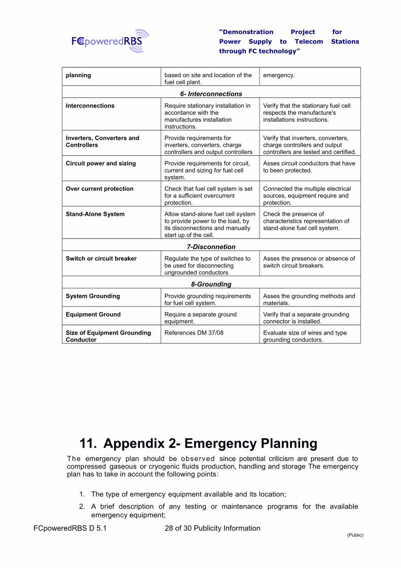
planning based on site and location of the fuel cell plant.
emergency.
6- Interconnections
Interconnections Require stationary installation in accordance with the manufactures installation instructions.
Verify that the stationary fuel cell respects the manufacture's installations instructions.
Inverters, Converters and Controllers
Provide requirements for inverters, converters, charge controllers and output controllers
Verify that inverters, converters, charge controllers and output controllers are tested and certified.
Circuit power and sizing Provide requirements for circuit, current and sizing for fuel cell system.
Asses circuit conductors that have to been protected.
Over current protection Check that fuel cell system is set for a sufficient overcurrent protection.
Connected the multiple electrical sources, equipment require and protection.
Stand-Alone System Allow stand-alone fuel cell systemto provide power to the load, by its disconnections and manually start up of the cell.
Check the presence of characteristics representation of stand-alone fuel cell system.
7-Disconnetion
Switch or circuit breaker Regulate the type of switches to be used for disconnecting ungrounded conductors
Asses the presence or absence of switch circuit breakers.
8-Grounding
System Grounding Provide grounding requirements for fuel cell system.
Asses the grounding methods andmaterials.
Equipment Ground Require a separate ground equipment.
Verify that a separate grounding connector is installed.
Size of Equipment Grounding Conductor
References DM 37/08 Evaluate size of wires and type grounding conductors.
11. Appendix 2- Emergency PlanningThe emergency plan should be observed since potential criticism are present due tocompressed gaseous or cryogenic fluids production, handling and storage The emergencyplan has to take in account the following points:
1. The type of emergency equipment available and its location;
2. A brief description of any testing or maintenance programs for the availableemergency equipment;
FCpoweredRBS D 5.1 28 of 30 Publicity Information(Public)

“Demonstration Project for
Power Supply to Telecom Stations
through FC technology”
3. An indication that hazard identification labeling is provided for each storage area;
4. The location of posted emergency procedures;
5. A list, including quantities, of compressed gases and cryogenic liquids and theirmaterials safety data sheets;
6. A facility site plan including the following information:
◦ Storage and use areas;
◦ Maximum amount of each material stored or used in each area;
◦ Container sizes;
◦ The location of gas and liquid conveying pipes;
◦ Locations of emergency isolation and mitigation valves and devices;
◦ Indications about ON and OFF positions of valves;
◦ A storage plan including arrangement of storage, the location anddimensions of walkways.
7. A list of personnel who are designated to care emergency services and who areresponsible for knowing the site emergency procedures.
12. Appendix 3- Evaluation Methodology ofRisk Assessment
A list of steps that have to be complete in order to assess necessary step to evaluaterisk is provided below:
1- Hazards Identifications.
Types of hazard are different according the installation considered and the aspectto evaluate. They are connected to: site location, site evaluation, hydrogen storagelocation, security, choice of materials, access, deliberate attack and vandalism,impact, ventilation, fire protection, location of safety sensors, connection to grid.
2- Decide who may be harmed and how.
FCpoweredRBS D 5.1 29 of 30 Publicity Information(Public)

“Demonstration Project for
Power Supply to Telecom Stations
through FC technology”
For each hazard identified in Step 1 assess who might be harmed and how.
3- Evaluate the risks and decide what to do about them
Consideration about removing the hazard and if that is not possible, how thehazard can be reduced or controlled.
4-Record and implement the findings
The risk assessment should show that all significant hazards have been recordedand addressed and how the hazards will be eliminated or if they cannot be eliminatedhow their effects will be minimized. Employees must be informed about the outcomeof the risk assessment. The precautions taken should be reasonable and if there is aresidual risk it should be low.
5-Review the Risk Assessment and update if and when necessary
Keeping update the records of the installation, maintenance checks and servicingshould be kept. Existing control measurements are to be take into account accordingan accurate identification of hazards and instruments available and necessary toprevent and protect against them.
FCpoweredRBS D 5.1 30 of 30 Publicity Information(Public)