Tse 1992 Multi Bar Columns
5
The Structural Engineer , Vol. 70, No. 23/24, 8 Dec. 1992 Simple design of multibar concrete columns A. N. Beal BSc CEng MIStructE MICE (Thomason Partnership) F. N. Pannell BSc MSTech PhD CEng MlStructE Introduction Reinforced concrete columns are now often designed by computer but design charts are still a popular alternative. Many sets of charts h ave been published for different Codes of Practice over the years, by various authors, but most of those for rectangular columns (e.g. BS8110:Part 3 [1]and the IStructE manual [2]) cover only columns that are reinforced with four bars placed near their corners. While this is probably the most common bar arrangement, many columns in practice - particularly the larger sizes - may have six, eight or more bars placed in a variety of arrangements (Fig. 1). As most columns are subjected to a degree of biaxial bending, it is therefore often necessary to design reinforcement or assess the resistance moment for one of these less efficient arrangements. Fig. 1 Common bar arrangements in RC columns Pannell [3] published comprehensi ve charts for the design of multibar columns to CPI14. These are effective but rather laborious to use; for accurate design they have been effectively superseded by the use of computer programs. However a full rigorous analysis is not always wanted and there is a need for a simple, approximate method of design. The IStructE manual gives an approximate method for multibar columns: any bars in the side faces of the column are simply ignored and only the outer bars are considered in the analysis. Fig. 2 shows the compari son between ri gorous BS 8110 analysis and this approximate method for a six-bar column with d = 0.85h. The approximate method is simple and always errs on the safe side but, as can be seen, the result can be very conservative when the axial force is high and the moment is low. The BS8110 handbook [4] suggests an alternative method: for calculation purposes the six, eight or more bars in the column are replaced b y four bars of equivalent total area, placed at the centroid of the group of bars on each side of the neutral axis. This avoids the conservatism of the ‘green book’ method when moments are low, giving clearly better results (see Fig . 2), However, the method is still conservative and six bar columns with d of less than 0.875h (equivalent four-bar effective depth d = 0.75h) cannot be analysed using the BS8110 charts, which do not extend to below d = 0.75h.
-
Upload
roberto-carlos -
Category
Documents
-
view
218 -
download
0
Transcript of Tse 1992 Multi Bar Columns

8/12/2019 Tse 1992 Multi Bar Columns
http://slidepdf.com/reader/full/tse-1992-multi-bar-columns 1/5
The Structural Engineer , Vol. 70, No. 23/24, 8 Dec. 1992
Simple design of multibar concrete columns
A. N. Beal BSc CEng MIStructE MICE (Thomason Partnership)
F. N. Pannell BSc MSTech PhD CEng MlStructE
Introduction
Reinforced concrete columns are now often designed by computer but design charts are still a popularalternative. Many sets of charts have been published for different Codes of Practice over the years, by various
authors, but most of those for rectangular columns (e.g. BS8110:Part 3 [1]and the IStructE manual [2]) cover
only columns that are reinforced with four bars placed near their corners.
While this is probably the most common bar arrangement, many columns in practice - particularly the larger
sizes - may have six, eight or more bars placed in a variety of arrangements (Fig. 1). As most columns are
subjected to a degree of biaxial bending, it is therefore often necessary to design reinforcement or assess the
resistance moment for one of these less efficient arrangements.
Fig. 1 Common bar arrangements in RC columns
Pannell [3] published comprehensive charts for the design of multibar columns to CPI14. These are effective
but rather laborious to use; for accurate design they have been effectively superseded by the use of computer
programs. However a full rigorous analysis is not always wanted and there is a need for a simple, approximate
method of design.
The IStructE manual gives an approximate method for multibar columns: any bars in the side faces of the
column are simply ignored and only the outer bars are considered in the analysis. Fig. 2 shows the comparison
between rigorous BS 8110 analysis and this approximate method for a six-bar column with d = 0.85h. The
approximate method is simple and always errs on the safe side but, as can be seen, the result can be very
conservative when the axial force is high and the moment is low.
The BS8110 handbook [4] suggests an alternative method: for calculation purposes the six, eight or more
bars in the column are replaced by four bars of equivalent total area, placed at the centroid of the group of barson each side of the neutral axis. This avoids the conservatism of the ‘green book’ method when moments are
low, giving clearly better results (see Fig. 2), However, the method is still conservative and six bar columns
with d of less than 0.875h (equivalent four-bar effective depth d = 0.75h) cannot be analysed using the BS8110charts, which do not extend to below d = 0.75h.

8/12/2019 Tse 1992 Multi Bar Columns
http://slidepdf.com/reader/full/tse-1992-multi-bar-columns 2/5
8/12/2019 Tse 1992 Multi Bar Columns
http://slidepdf.com/reader/full/tse-1992-multi-bar-columns 3/5
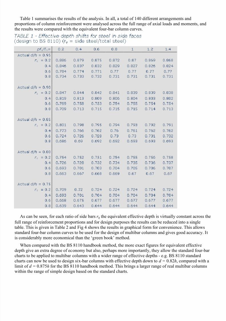
Table 1 summarises the results of the analysis. In all, a total of 140 different arrangements and
proportions of column reinforcement were analysed across the full range of axial loads and moments, and
the results were compared with the equivalent four-bar column curves.
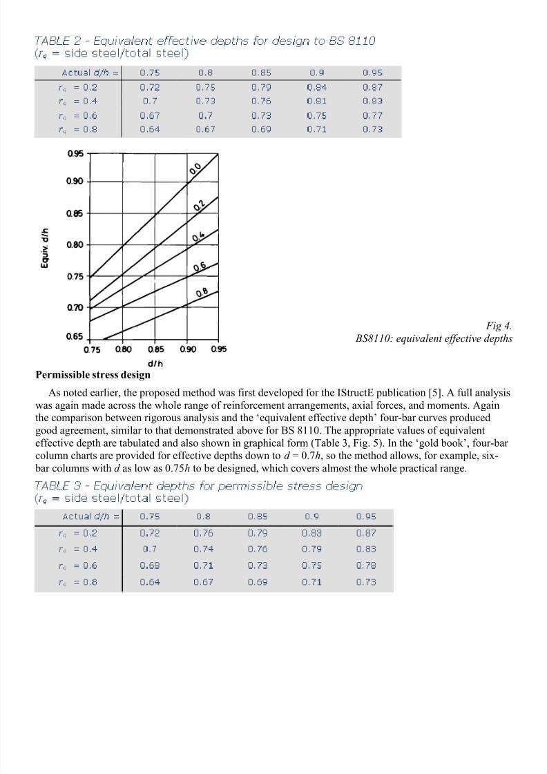
As can be seen, for each ratio of side bars r q the equivalent effective depth is virtually constant across the
full range of reinforcement proportions and for design purposes the results can be reduced into a single
table. This is given in Table 2 and Fig 4 shows the results in graphical form for convenience. This allows
standard four-bar column curves to be used for the design of multibar columns and gives good accuracy. It
is considerably more economical than the ‘green book’ method.
When compared with the BS 8110 handbook method, the more exact figures for equivalent effective
depth give an extra degree of economy but also, perhaps more importantly, they allow the standard four-bar
charts to be applied to multibar columns with a wider range of effective depths - e.g. BS 8110 standard
charts can now be used to design six-bar columns with effective depth down to d = 0.82h, compared with a
limit of d = 0.875h for the BS 8110 handbook method. This brings a larger range of real multibar columns
within the range of simple design based on the standard charts.
8/12/2019 Tse 1992 Multi Bar Columns
http://slidepdf.com/reader/full/tse-1992-multi-bar-columns 4/5
Fig 4.
BS8110: equivalent effective depths
Permissible stress design
As noted earlier, the proposed method was first developed for the IStructE publication [5]. A full analysis
was again made across the whole range of reinforcement arrangements, axial forces, and moments. Againthe comparison between rigorous analysis and the ‘equivalent effective depth’ four-bar curves produced
good agreement, similar to that demonstrated above for BS 8110. The appropriate values of equivalent
effective depth are tabulated and also shown in graphical form (Table 3, Fig. 5). In the ‘gold book’, four-bar
column charts are provided for effective depths down to d = 0.7h, so the method allows, for example, six-
bar columns with d as low as 0.75h to be designed, which covers almost the whole practical range.

8/12/2019 Tse 1992 Multi Bar Columns
http://slidepdf.com/reader/full/tse-1992-multi-bar-columns 5/5
Fig 5.
Permissible stress design: equivalent effective depths
Conclusions
Multibar rectangular concrete columns can be designed using the published curves for four- bar columns
if the effective depth of the multibar column is transformed into an equivalent four-bar effective depth. The
coefficients vary with the proportion of steel placed in the sides of the section. The method gives ample
accuracy for most normal design, making more elaborate analysis unnecessary. The method can be used
with either limit state or permissible stress design Codes and provides a simple, more accurate alternative to
the approximate method suggested in the IStructE manual (the ‘green book’). It is also more accurate and
more widely applicable than the approximate method proposed in the BS 8110 handbook.
References
1. BS 8110 Structural use of concrete: Part 3, London, British Standards Institution, 1985.
2. IStructE/ICE Manual for the design of reinforced concrete building structures, London, Institution of Structural
Engineers, 1985.
3. Pannell, F. N.: Design charts for members subjected to biaxial bending and thrust, London, Concrete Publications Ltd
4. Rowe, R. E., et al: Handbook to British Standard BS8110, Palladian Pubs Ltd, London, 1987, p. 64.
5. Recommendations for the permissible stress design of reinforced concrete building structures, London, Institution of
Structural Engineers, 1991.