Truck Essential Power Systems Efficiency Improvements for ...
35
Page 1 Truck Essential Power Systems Efficiency Improvements for Medium Duty Trucks HVSO Review Meeting April 20, 2006 Powering The Future ®
Transcript of Truck Essential Power Systems Efficiency Improvements for ...

Page 1
Truck Essential Power Systems Efficiency Improvements for Medium Duty Trucks
HVSO Review Meeting
April 20, 2006
Powering The Future®
Page 2
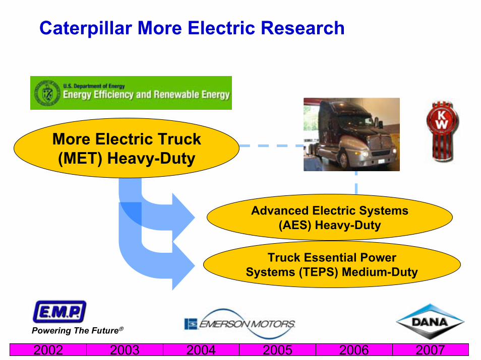
Caterpillar More Electric Research
Advanced Electric Systems (AES) Heavy-Duty
Truck Essential Power Systems (TEPS) Medium-Duty
2002 2003 2004 2005 2006 2007Powering The Future®
More Electric Truck (MET) Heavy-Duty

Page 3
Program Overview
Three year programThree Tasks– Task 101 - Specifications,
Concepts, and Designs– Task 102 – Bench Testing– Task 103 – Integration,
Testing, Reporting2004/2005 2006 2007
Page 4
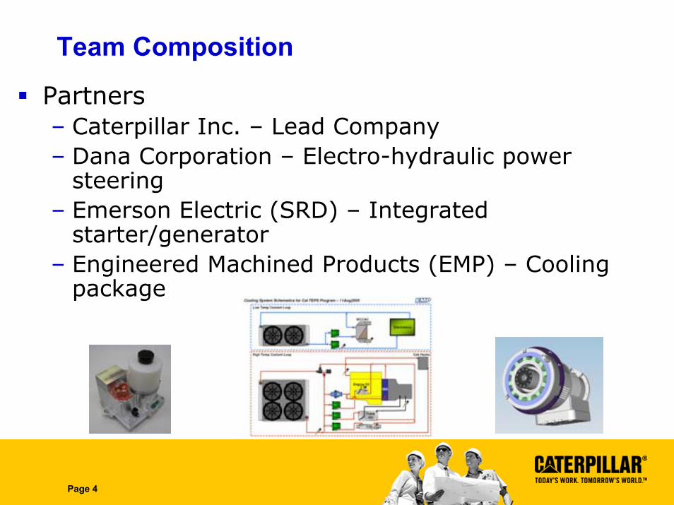
Team Composition
Partners– Caterpillar Inc. – Lead Company– Dana Corporation – Electro-hydraulic power
steering– Emerson Electric (SRD) – Integrated
starter/generator– Engineered Machined Products (EMP) – Cooling
package
Page 5
Mission
Improve vehicle fuel economy– Reduce parasitic loads– Improve operational efficiency– Idle reduction
Reduce emissionsOffer chassis enhancements– Field power– Alternative power sources
Demonstrate on a medium duty platformDemonstrate on a medium duty platform

Page 6
Vision
Truck electrification delivers reduced fuel consumption and idle reduction opportunities. Advanced technologies facilitate fuel economy gains as well as chassis enhancements. Electrification expands the boundaries for capability, comfort, and power source diversity in a more fuel efficient package.
10% reduction in fuel consumption
Beltless engine
Field powerEfficient cab comfort
Brake energy reclaim
Idle reduction

Page 7
Market Analysis
QFD w/ OEM Truck Company– VOC– VOB– MD Vocations– Powertrain Configuration
Utility Truck
VOC
: Pay
load
VOC
: Sto
rage
spa
ce
VOC
: Ret
ain
Func
tiona
lity
VOC
: Mai
nten
ance
(whe
re
VOC
: Cos
t of a
cqui
sitio
n
Fuel
Eco
nom
y
Dri
ver
/ Ope
rato
r Sa
ftey
Sum
of N
orm
aliz
ed R
atin
gs
Relative Score
VOC: Payload 1.00 0.50 0.50 3.00 3.00 1.00 0.50 0.98 14.0%
VOC: Storage space 2.00 1.00 0.50 2.00 2.00 1.00 0.50 1.00 14.2%
VOC: Retain Functionality 2.00 2.00 1.00 3.00 2.00 3.00 0.50 1.44 20.6%
VOC: Maintenance (where take it) 0.33 0.50 0.33 1.00 0.50 2.00 0.50 0.57 8.1%
VOC: Cost of acquisition 0.33 0.50 0.50 2.00 1.00 2.00 0.50 0.72 10.2%
Fuel Economy 1.00 1.00 0.33 0.50 0.50 1.00 0.25 0.53 7.6%
Driver / Operator Saftey 2.00 2.00 2.00 2.00 2.00 4.00 1.00 1.77 25.2%
Row Names
Delivery Truck
Ope
rato
r Fr
iend
lines
s (d
r
Non
- Man
ual T
rans
mis
sio
All
Envi
ronm
ents
VOC
: Can
I se
ll w
hen
I'm
Res
idua
l val
ue
VOC
: Gri
d Sa
les
VOC
: Ade
quat
e En
ergy
tim
Sum
of N
orm
aliz
ed R
atin
gs
Relative Score
Operator Friendliness (drive like m 1.00 1.00 1.00 1.00 0.50 9.00 9.00 1.21 17.3%
Non- Manual Transmission 1.00 1.00 1.00 2.00 2.00 9.00 9.00 1.48 21.1%
All Environments 1.00 1.00 1.00 1.00 9.00 9.00 9.00 1.83 26.1%
VOC: Can I sell when I'm done 1.00 0.50 1.00 1.00 1.00 9.00 9.00 1.13 16.1%
Residual value 2.00 0.50 0.11 1.00 1.00 9.00 9.00 1.08 15.5%
VOC: Grid Sales 0.11 0.11 0.11 0.11 0.11 1.00 1.00 0.14 2.0%
VOC: Adequate Energy time 0.11 0.11 0.11 0.11 0.11 1.00 1.00 0.14 2.0%
Row Names
Page 8
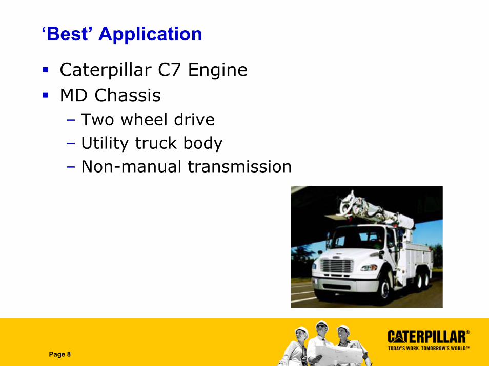
‘Best’ Application
Caterpillar C7 EngineMD Chassis– Two wheel drive– Utility truck body– Non-manual transmission
Page 9
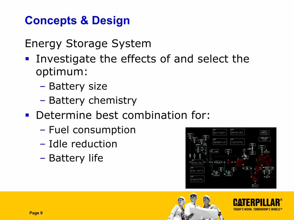
Concepts & Design
Energy Storage SystemInvestigate the effects of and select the optimum:– Battery size– Battery chemistry
Determine best combination for:– Fuel consumption– Idle reduction– Battery life

Page 10
Energy Storage Technologies
Lead Acid battery pack• 4 KWH, 6 KWH, 8KWH, 16 KWH
Ni-MH battery pack• 2.4 KWH, 4.8 KWH
Li Ion Battery pack • 2 KWH

Page 11
Observations
Battery size does not have a significant effect on fuel efficiency, but does impact idle reduction capability.Increasing battery size reduces the number of required battery cycles, thus prolonging battery life.
Battery Technology
Size(Wh)
Weight(kg)
Est. Life(yrs.)
VRLA 16000 400 5
NiMH 1500 46 4
Li-Ion 2000 33 4

Page 12
Energy Storage Selection
Nominal Voltage 288VEnergy 2.4kWhPower 60kWDimensions 430x850x 210mmWeight 75kg

Page 13
Integrated Starter/Generator (ISG)
Provided by Switched Reluctance Drives Ltd. (SRD)Switched reluctance machine20kW powerLiquid cooled, max. inlet 100°CNominal voltage range: 209-372 VSupplied as a rotor and a liquid cooled stator, suitable for fitting within an engine mounted housing

Page 14
ISG Electronics Design
Water cooled heatsinkIGBT modules in placeCapacitors in placeCurrent transducers and terminal bar in placeControl electronics in place

Page 15
ISG Electronics Hardware
Heatsink and Capacitors
Current Transducer and Terminal Bar
DSP-based Control PCB

Page 16
ISG Mechanical Design
Stator Rotor ISG Assembly
Page 17
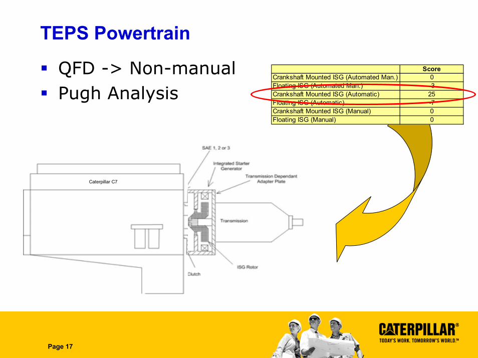
TEPS Powertrain
QFD -> Non-manualPugh Analysis
ScoreCrankshaft Mounted ISG (Automated Man.) 0Floating ISG (Automated Man.) -3Crankshaft Mounted ISG (Automatic) 25Floating ISG (Automatic) -7Crankshaft Mounted ISG (Manual) 0Floating ISG (Manual) 0
Caterpillar C7

Page 18
Powertrain Design

Page 19
Electro-Hydraulic Power Steering (EHPS)
Provided by DanaElectro-hydraulic boosterOperation on demandBuilds on previous efforts

Page 20
12V
550W
42V
1.6KW
12V
700W
300V
3KW
Power Road Map

Page 21
Prototype Unit
Performance @ 300V 50oC
– Output• 19 l/m
@150Bar– Overall efficiency
• 74%Weight ~ 3.5kg

Page 22
Cooling Package
Provided by EMPIncreased heat rejectionElectric devices– On-demand– Variable speed
Powering The Future®

Page 23
Thermal Loads
High Temperature Loop ~ 200 kW– Engine– ISG Machine– TransmissionLow Temperature Loop ~ 22 kW– Power Electronics– Charge Air– Energy Storage
Page 24
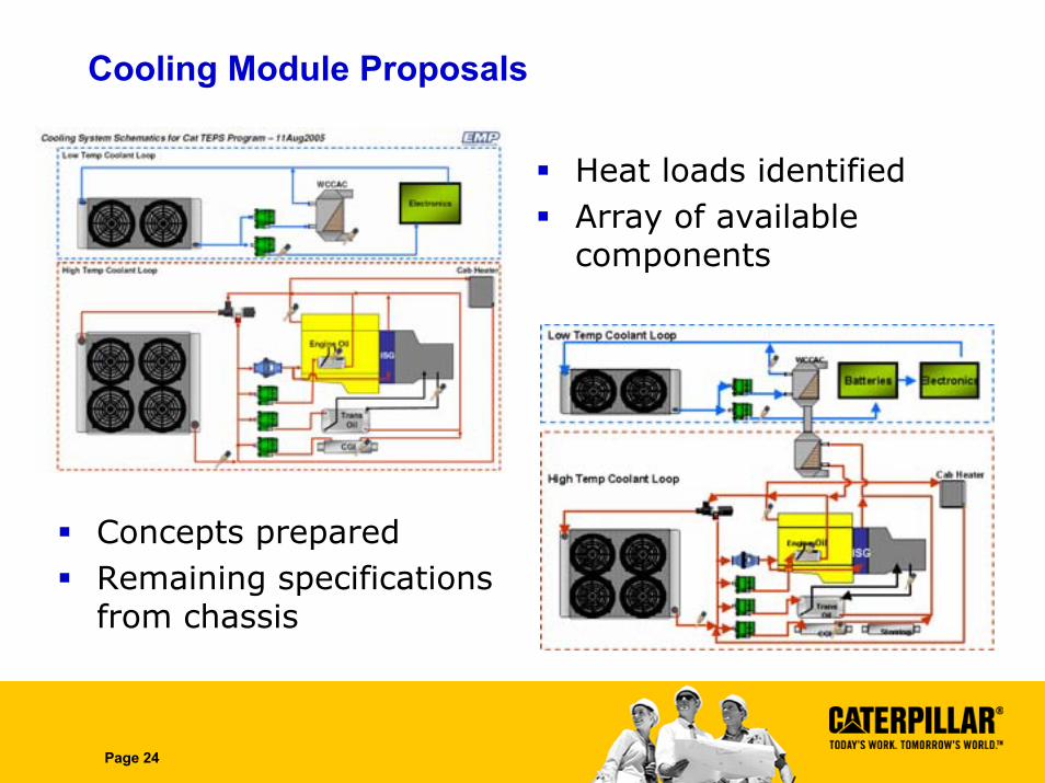
Cooling Module Proposals
Heat loads identifiedArray of available components
Concepts preparedRemaining specifications from chassis

Page 25
ISG Supervisory Control
Make efficient use of the ISG as motor or generator in different truck operation scenarios to reduce the fuel consumption. Operating modes:– Engine start/stop– Generate during brake events– Engine shut down for reduced idle at job
site– Potential to provide additional tractive
power

Page 26
Controller model
ISG Routines
Mtr/Gen Routines
Generator Control
Motor control

Page 27
Co-Simulation
MATLAB Dynasty

Page 28
Results – Utility Cycle

Page 29
Simulation Results – Utility Cycle
Utility Truck Route – 13 stop lights – 1 job site of 95 min duration – Truck speeds between 0-60 kph
Fuel Consumption Improvements:– Jobsite: ~ 80%– Road travel: ~ 20%– Complete route: ~ 45%

Page 30
Results – 5Star Cycle

Page 31
Simulation Results – 5Star Cycle
Delivery Route – Top speed = 48.5 mph – Average Speed = 18.6 mph
Fuel Consumption Improvements:– Complete route: ~ 30%

Page 32
Potential Impact
Assume 30% reduction in fuel consumption– 30 L/100km 21 L/100km– 7.8 MPG 11.2 MPG
17K Annual Miles 2200 gal vs. 1500 gal
900K Class 6 Vehicles 630M gal/yr
@ $2.75/gal $1.7B/yr

Page 33
Program Accomplishments
Team formedApplication/architecture definedISG electronics downsized and assembledElectrical architectureEnergy storage specifiedEHPS assembled and testingIntegration PCB’s assembled and testedChassis selectedDetailed model/simulations developed
Page 34
Looking Ahead – 2006
ISG Fabricated & Assembled – 5/2006EHPS Bench Testing – 6/2006ISG Bench Testing – 8/2006Control Algorithms Written – 6/2006Baseline Testing – 7/2006Vehicle Integration – 8/2006+

Page 35
Thank You…