TR 103 103 - V1.1.1 - Fixed Radio Systems; Point-to-point systems ...
22
ETSI TR 103 103 V1.1.1 (2012-09) Fixed Radio Systems; Point-to-point systems; ATPC, RTPC, Adaptive Modulation (mixed-mode) and Bandwidth Adaptive functionalities; Technical background and impact on deployment, link design and coordination Technical Report
Transcript of TR 103 103 - V1.1.1 - Fixed Radio Systems; Point-to-point systems ...

ETSI TR 103 103 V1.1.1 (2012-09)
Fixed Radio Systems; Point-to-point systems;
ATPC, RTPC, Adaptive Modulation (mixed-mode) and Bandwidth Adaptive functionalities;
Technical background and impact on deployment, link design and coordination
Technical Report

ETSI
ETSI TR 103 103 V1.1.1 (2012-09) 2
Reference DTR/ATTM-04024
Keywords adaption, DFRS, point-to-point, modulation
ETSI
650 Route des Lucioles F-06921 Sophia Antipolis Cedex - FRANCE
Tel.: +33 4 92 94 42 00 Fax: +33 4 93 65 47 16
Siret N° 348 623 562 00017 - NAF 742 C
Association à but non lucratif enregistrée à la Sous-Préfecture de Grasse (06) N° 7803/88
Important notice
Individual copies of the present document can be downloaded from: http://www.etsi.org
The present document may be made available in more than one electronic version or in print. In any case of existing or perceived difference in contents between such versions, the reference version is the Portable Document Format (PDF).
In case of dispute, the reference shall be the printing on ETSI printers of the PDF version kept on a specific network drive within ETSI Secretariat.
Users of the present document should be aware that the document may be subject to revision or change of status. Information on the current status of this and other ETSI documents is available at
http://portal.etsi.org/tb/status/status.asp
If you find errors in the present document, please send your comment to one of the following services: http://portal.etsi.org/chaircor/ETSI_support.asp
Copyright Notification
No part may be reproduced except as authorized by written permission. The copyright and the foregoing restriction extend to reproduction in all media.
© European Telecommunications Standards Institute 2012.
All rights reserved.
DECTTM, PLUGTESTSTM, UMTSTM and the ETSI logo are Trade Marks of ETSI registered for the benefit of its Members. 3GPPTM and LTE™ are Trade Marks of ETSI registered for the benefit of its Members and
of the 3GPP Organizational Partners. GSM® and the GSM logo are Trade Marks registered and owned by the GSM Association.

ETSI
ETSI TR 103 103 V1.1.1 (2012-09) 3
Contents
Intellectual Property Rights ................................................................................................................................ 4
Foreword ............................................................................................................................................................. 4
1 Scope ........................................................................................................................................................ 5
2 References ................................................................................................................................................ 5
2.1 Normative references ......................................................................................................................................... 5
2.2 Informative references ........................................................................................................................................ 5
3 Definitions, symbols and abbreviations ................................................................................................... 6
3.1 Definitions .......................................................................................................................................................... 6
3.2 Symbols .............................................................................................................................................................. 6
3.3 Abbreviations ..................................................................................................................................................... 6
4 Impact of power control (ATPC and/or RTPC), mixed-mode and bandwidth adaptive operation on spectrum mask and link design requirements ...................................................................................... 7
4.1 ATPC and RTPC implementation background .................................................................................................. 7
4.1.1 RTPC Impact ................................................................................................................................................ 8
4.1.2 ATPC impact ................................................................................................................................................ 9
4.1.2.1 ATPC not required as licensing/coordination conditions ........................................................................ 9
4.1.2.1.1 Use in bands where conventional coordination is applied ................................................................. 9
4.1.2.1.2 Use in bands where no coordination or simpler self-coordination is applied .................................. 10
4.1.2.2 ATPC required as licensing/coordination conditions ............................................................................ 11
4.2 Mixed-mode operation impact ......................................................................................................................... 11
4.2.1 Basic concepts ............................................................................................................................................ 11
4.2.2 Link availability .......................................................................................................................................... 12
4.2.3 Link fade margin ......................................................................................................................................... 13
4.2.4 ATPC range ................................................................................................................................................ 14
4.3 Bandwidth adaptive operation impact .............................................................................................................. 18
4.3.1 Basic concepts ............................................................................................................................................ 18
4.3.2 Bandwidth (channel) occupancy ................................................................................................................. 18
4.3.3 Link availability and fade margin ............................................................................................................... 18
4.3.4 ATPC range ................................................................................................................................................ 18
5 Impact on frequency co-ordination ........................................................................................................ 19
6 Impact on Article 3.2 "essential" parameters and operating conditions ................................................. 20
History .............................................................................................................................................................. 22
ETSI
ETSI TR 103 103 V1.1.1 (2012-09) 4
Intellectual Property Rights IPRs essential or potentially essential to the present document may have been declared to ETSI. The information pertaining to these essential IPRs, if any, is publicly available for ETSI members and non-members, and can be found in ETSI SR 000 314: "Intellectual Property Rights (IPRs); Essential, or potentially Essential, IPRs notified to ETSI in respect of ETSI standards", which is available from the ETSI Secretariat. Latest updates are available on the ETSI Web server (http://ipr.etsi.org).
Pursuant to the ETSI IPR Policy, no investigation, including IPR searches, has been carried out by ETSI. No guarantee can be given as to the existence of other IPRs not referenced in ETSI SR 000 314 (or the updates on the ETSI Web server) which are, or may be, or may become, essential to the present document.
Foreword This Technical Report (TR) has been produced by ETSI Technical Committee Access, Terminals, Transmission and Multiplexing (ATTM).

ETSI
ETSI TR 103 103 V1.1.1 (2012-09) 5
1 Scope The present document aims to facilitate the correct understanding of the use of the following functionalities widely used in point-to-point fixed radio systems in the context of network coordination with a view to R&TTE Directive [i.1] assessment procedures:
• Remote Transmit Power Control (RTPC).
• Automatic Transmit Power Control (ATPC).
• Mixed-mode (also known as Adaptive modulation) operation.
• Bandwidth adaptive operation.
The technical content has been derived from extensive technical background originally placed in EN 302 217-2-2 [i.5] and subsequently improved and moved, as stand alone text, to the present document.
Therefore, the scope of the present document is also to assist the correct understanding of the requirements in EN 302 217−2−2 [i.5] and their consequent assessment.
2 References References are either specific (identified by date of publication and/or edition number or version number) or non-specific. For specific references, only the cited version applies. For non-specific references, the latest version of the reference document (including any amendments) applies.
Referenced documents which are not found to be publicly available in the expected location might be found at http://docbox.etsi.org/Reference.
NOTE: While any hyperlinks included in this clause were valid at the time of publication, ETSI cannot guarantee their long term validity.
2.1 Normative references The following referenced documents are necessary for the application of the present document.
Not applicable.
2.2 Informative references The following referenced documents are not necessary for the application of the present document but they assist the user with regard to a particular subject area.
[i.1] Directive 1999/5/EC of the European Parliament and of the Council of 9 March 1999 on radio equipment and telecommunications terminal equipment and the mutual recognition of their conformity (R&TTE Directive).
[i.2] ECC/REC(01)05: "List of parameters of digital point-to-point fixed radio links used for national planning".
[i.3] ETSI EN 302 217-1: "Fixed Radio Systems; Characteristics and requirements for point-to-point equipment and antennas; Part 1: Overview and system-independent common characteristics".
[i.4] ETSI EN 302 217-2-1 (V1.3.1): "Fixed Radio Systems; Characteristics and requirements for point-to-point equipment and antennas; Part 2-1: System-dependent requirements for digital systems operating in frequency bands where frequency co-ordination is applied".

ETSI
ETSI TR 103 103 V1.1.1 (2012-09) 6
[i.5] ETSI EN 302 217-2-2: "Fixed Radio Systems; Characteristics and requirements for point-to-point equipment and antennas; Part 2-2: Digital systems operating in frequency bands where frequency co-ordination is applied; Harmonized EN covering the essential requirements of Article 3.2 of the R&TTE Directive".
[i.6] ETSI EN 302 217-3: "Fixed Radio Systems; Characteristics and requirements for point-to-point equipment and antennas; Part 3: Equipment operating in frequency bands where both frequency coordinated or uncoordinated deployment might be applied; Harmonized EN covering the essential requirements of Article 3.2 of the R&TTE Directive".
[i.7] ETSI EN 302 326-2: "Fixed Radio Systems; Multipoint Equipment and Antennas; Part 2: Harmonized EN covering the essential requirements of Article 3.2 of the R&TTE Directive for Digital Multipoint Radio Equipment".
[i.8] ITU-R Recommendation P.530: "Propagation data and prediction methods required for the design of terrestrial line-of-sight systems".
3 Definitions, symbols and abbreviations
3.1 Definitions For the purposes of the present document, the terms and definitions given in EN 302 217-1 [i.3] apply.
3.2 Symbols For the purposes of the present document, the following symbols apply:
dB deciBel dBm deciBel relative to 1 mW GHz GigaHertz MHz MegaHertz
3.3 Abbreviations For the purposes of the present document, the following abbreviations apply:
ATPC Automatic Transmit Power Control ATTM ETSI TC-Access Terminals, Transmission and Multiplexing BER Bit Error Ratio BPSK Binary Phase Shift Keying C/I Carrier to Interference ratio CEPT Conférence des administrations Européennes des Postes et Télécommunications ECC Electronic Communication Committee of the CEPT EHF Extremely High Frequency EIRP Equivalent Isotropically Radiated Power ERC European Radiocommunications Committee of the CEPT, presently become ECC FM Fade Margin ITU-R International Telecommunication Union - Radiocommunications standardization sector MP MultiPoint NFD Net Filter Discrimination PMP Binary Phase Shift Keying P-MP Point-to-Multipoint PP Point to Point P-P Point-to-Point PSK Phase Shift Keying QAM Quadrature Amplitude Modulation QPSK Quadrature Phase Shift Keying R&TTE Radio and Telecommunication Terminal Equipment

ETSI
ETSI TR 103 103 V1.1.1 (2012-09) 7
R&TTE Radio equipment and Telecommunications Terminal Equipment RBER Residual BER RF Radio Frequency RSL Receiver Signal Level RTPC Remote Transmit Power Control RX Receive or Receiver S/(N+I) Signal to Noise plus Interference Ratio S/N Signal to Noise ratio SW SoftWare TC Technical Committee TX Transmit or Transmitter
4 Impact of power control (ATPC and/or RTPC), mixed-mode and bandwidth adaptive operation on spectrum mask and link design requirements
4.1 ATPC and RTPC implementation background It is worth explaining that, in most practical applications, ATPC and RTPC are realized by a single function SW programmable system; therefore it is the supplier that should declare how the available range of attenuation should be subdivided (and possibly limited) in order to meet the normative conditions contained in the relevant ETSI Harmonized Standards and/or in other regulatory limits eventually defined by administrations in the licensing conditions. Those conditions are summarized below.
It is important to understand that the total available range of attenuation is, in general, subdivided in two sub-ranges, which, in principle, are independent from any "labelling" as RTPC or ATPC ranges:
• "Initial" Sub-range where the required spectrum mask is still fulfilled;
• "Final" Sub-range where the required spectrum mask is no longer fulfilled.
The ATPC sub-range may be used within two possible scenarios synthesised by table 1.
Table 1: ATPC operating modes versus licensing conditions
Coordination/licensing conditions
Effect on network Operational needs
No ATPC is imposed but the user(s), under his (their) responsibility, apply an ATPC reduction in a homogeneous area for general improvement of the interference situation.
Interference impact on performance and availability is still evaluated with power at nominal level (no ATPC attenuation is considered in the coordination process); therefore: • No improvement in the network density. • The user under his own responsibility might obtain
additional margin against the calculated performance and availability objectives.
No need for fulfilling the spectrum mask (and NFD) in the ATPC range, which can indifferently use "initial" and/or "final" sub-ranges of attenuation.
ATPC is imposed as pre-condition of coordination/licensing (note 1).
Interference impact on performance and availability is evaluated with power reduced by an ATPC range; therefore: • Improvement in the network density could be obtained
(note 2). • No additional margin against the calculated performance
and availability objectives (note 3).
Need for fulfilling the spectrum mask (and NFD) in the assumed ATPC range, which is supposed to remain within "initial" sub-range of attenuation.
NOTE 1: The ATPC range is link-by-link dependent, it is usually determined in order to fix the maximum RSL permitted during unfaded periods.
NOTE 2: In general the use of ATPC pre-condition is possible for new links in a network; if existing links in already dense networks were coordinated without any ATPC, the possible density improvement might be severely reduced.
NOTE 3: However, in principle and if possible and practical, improvement might still be obtained using the residual ATPC attenuation, under operator responsibility.

ETSI
ETSI TR 103 103 V1.1.1 (2012-09) 8
Therefore, from the point of view of equipment use in the network, the RTPC and ATPC "labelling" of the available attenuation range is, in principle, different for the two cases considered in table 1; figure 1 summarises this aspect (see note).
NOTE: The use of ATPC in the license conditions is foreseen in some countries on national basis; in addition, the implementation of ATPC functionality is left, as an option, to manufacturer choice. Therefore, the ATPC assessment for specific licensing conditions is not retained "essential" for R&TTE Directive [i.1] point of view. Nevertheless, the supplier is recommended to define the RTPC/ATPC ranges possibly available for that purpose.
Tota
l ran
ge o
f pow
er c
ontr
ol
Max
imum
ran
ge o
f pow
er c
ontr
ol
fulf
illin
g th
e sp
ectr
um m
ask
(“In
itia
l” s
ub-r
ange
) RTPC/ATPC range subdivision(possibly depending on RTPC need for
obtaining the licensed e.i.r.p.)
Ran
ge u
sabl
e fo
r R
TP
C a
nd/o
r A
TP
C(u
nder
use
r re
spon
sibi
lity)
Ran
ge u
sabl
e fo
r A
TP
C o
nly
(und
er u
ser
resp
onsi
bilit
y)
Ran
ge o
f po
wer
con
trol
not
fu
lfill
ing
the
spec
trum
mas
k(“
Fin
al”
sub-
rang
e)
Maximum nominal power
Minimum power
Max
imum
ran
ge u
sabl
e fo
r A
TP
C
(use
able
for
licen
sing
con
diti
ons)
Shor
ter
hops
red
uced
AT
PC
ran
ge (u
seab
le f
or
licen
sing
con
diti
ons)
Shor
ter
hops
R
TP
C r
ange
Technical limitations
Limitations when ATPC is not used as licensing/coordination condition
(ATPC may still be used only under user responsibility for improving its own network density)
Limitations whenATPC is used as
licensing/coordination condition
Ran
ge u
sabl
e fo
r fu
rthe
r A
TP
C r
ange
(u
nder
use
r re
spon
sibi
lity)
Figure 1: ATPC/RTPC ranges and licensing/coordination conditions
4.1.1 RTPC Impact
It should be considered that, when RTPC is used as alternative for conventional RF attenuators (used in the past for a similar purpose) for setting the maximum power established in the network when planning for each single PP link in order to restrict inter-system interference into other links, the NFD should be maintained (because it is used for frequency planning and associated with a rated power). Therefore the mask should be met throughout the operating range offered (supplier should limit the available range of RTPC accordingly).
NOTE: The above description might not be directly applicable to Multi-Point (MP) applications because RTPC (if any) might be used in MP systems for different purposes, see EN 302 326-2 [i.7].

ETSI
ETSI TR 103 103 V1.1.1 (2012-09) 9
4.1.2 ATPC impact
4.1.2.1 ATPC not required as licensing/coordination conditions
4.1.2.1.1 Use in bands where conventional coordination is applied
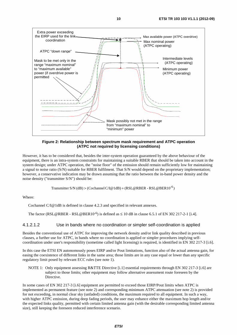
Figure 2 clarifies the technical background for the ATPC operations; it identifies the relevant power levels and their relationship with the transmitter power density spectrum mask as required by EN 302 217-2-2 [i.5] (see note 1) in relation to the Article 3.2 of R&TTE Directive [i.1].
NOTE 1: Presently, the large majority of licensing procedures in Europe do not impose an ATPC range; therefore, it is not considered to be an essential requirement in accordance with the R&TTE Directive [i.1]; more stringent spectrum usage scenarios (see next clause 4.2.1.2) are left to voluntary implementation of the manufacturer.
In figure 2 different power levels, possible during ATPC operation, are identified as follows:
• Maximum Nominal Power (ATPC operating): This is coincident with the EIRP defined in the coordination process for the required link availability (excluding the antenna gain).
• Minimum Power (ATPC operating): This is the lower power reached in unfaded (clear sky) propagation conditions. This level is defined on the basis of a minimum receiver signal level (RSL) guaranteeing stable "error free conditions" (including safeguard allowance for tolerances in both TX power setting and RX RSL detection).
• Intermediate Power (ATPC operating): Any intermediate power condition adapted to the instantaneous propagation condition.
• Maximum available power (ATPC overdrive): This is mentioned only for due background information of the technical capability of an ATPC system in a network; however, the applicability and the benefits of this "overdrive" feature in a multi-operator network are doubtful. It might be considered, with care, only when a single operator can be responsible for all mutually interfering links in a certain area and can actively monitor the network for possible unacceptable interference between links using this feature. Rationale is that this higher power might be provided by the equipment when the nominal power defined by the coordination process is lower than the equipment capability; in principle, this extra power might be activated by the ATPC system when the RSL becomes even lower than the BER threshold used for the required availability. This, still in principle, should happen for less than the unavailability time used for the network coordination (e.g. less than 0,01 % of the time if availability of 99,99 % is sought); therefore, the potential interference power increase towards other links in the area should happen only for a time percentage lower than their nominal unavailability. However, a number of practical considerations (e.g. activation threshold should be somehow higher than BER threshold for an "error free" operation, significant tolerance in detecting very low RSL, etc.) suggest that the actual activation time could become sensibly higher than ideal and the impact on other links nearby might no longer be negligible. Therefore, the applicability and benefit of this "overdrive" feature in a multi-operator network are considered unpractical.
The Rationale for the requirement related to respecting or not the spectrum mask (see note 2) is that while the mask is a "relative attenuation", the actual interference potential is given by the absolute power spill-over into adjacent channels. Therefore the NFD should be guaranteed when transmitters operate at maximum nominal power or in the overdrive region (i.e. when maximum absolute power is produced in adjacent channels), which are the conditions commonly used for frequency planning. In all lower power conditions, even where the NFD may be degraded by the (apparent) increase of the noise floor (due to the actual drop in carrier power), resulting in the mask level being exceeded (see figure 2), however the absolute interference power on adjacent channels will in any case be equal to or less than that used for planning (i.e. the planned C/I on adjacent channels will not be exceeded).
NOTE 2: In practice (see clause 4.2.2.1.1), if licensing conditions permits a limited EIRP increase for short periods, only the ATPC operating in the range between "maximum nominal power" and "maximum available power", including the relevant attenuation introduced by the RTPC function (if any) for setting the licensed level of EIRP, is relevant for maintaining the spectral emission within the mask and consequently the NFD.
ETSI
ETSI TR 103 103 V1.1.1 (2012-09) 10
Max available power (ATPC overdrive)
Max nominal power(ATPC operating)
Minimum power (ATPC operating)
Mask to be met only in the range “maximum nominal” to “maximum available” power (if overdrive power is permitted
Mask possibly not met in the range from “maximum nominal” to “minimum” power
Intermediate levels (ATPC operating)
ATPC “down range”
Extra power exceeding the EIRP used for the link
coordination
Figure 2: Relationship between spectrum mask requirement and ATPC operation (ATPC not required by licensing conditions)
However, it has to be considered that, besides the inter-system operation guaranteed by the above behaviour of the equipment, there is an intra-system constraints for maintaining a suitable RBER that should be taken into account in the system design; under ATPC operation, the "noise floor" of the emission should remain sufficiently low for maintaining a signal to noise ratio (S/N) suitable for RBER fulfilment. That S/N would depend on the proprietary implementation; however, a conservative indication may be drawn assuming that the ratio between the in-band power density and the noise density ("transmitter S/N") should be:
)RSL@BER10-(RSL@RBERC/I@1dB) Cochannel((dB) S/Nr Transmitte -6+>
Where:
Cochannel C/I@1dB is defined in clause 4.2.3 and specified in relevant annexes.
The factor (RSL@RBER - RSL@BER10-6) is defined as ≤ 10 dB in clause 6.5.1 of EN 302 217-2-1 [i.4].
4.1.2.1.2 Use in bands where no coordination or simpler self-coordination is applied
Besides the conventional use of ATPC for improving the network density and/or link quality described in previous clauses, a further use for ATPC, in bands where no coordination is applied or simpler procedures implying self-coordination under user's responsibility (sometime called light licensing) is required, is identified in EN 302 217-3 [i.6].
In this case the ETSI EN autonomously poses EIRP and/or Pout limitations, function also of the actual antenna gain, for easing the coexistence of different links in the same area; those limits are in any case equal or lower than any specific regulatory limit posed by relevant ECC rules (see note 1).
NOTE 1: Only equipment assessing R&TTE Directive [i.1] essential requirements through EN 302 217-3 [i.6] are subject to those limits; other equipment may follow alternative assessment route foreseen by the Directive.
In some cases of EN 302 217-3 [i.6] equipment are permitted to exceed those EIRP/Pout limits when ATPC is implemented as permanent feature (see note 2) and corresponding minimum ATPC attenuation (see note 2) is provided for not exceeding, in normal clear sky (unfaded) conditions, the maximum required to all equipment. In such a way, with higher ATPC emission, during deep fading periods, the user may enhance either the maximum hop length and/or the expected links quality, permitted with certain limited antenna gain (with the desirable corresponding limited antenna size), still keeping the foreseen reduced interference scenario.

ETSI
ETSI TR 103 103 V1.1.1 (2012-09) 11
The ATPC activation is intended as linearly activated by the drop of RSL in the corresponding far end receiver, so that the normal limits of EIRP/Pout, otherwise required to "non ATPC operated" equipment, can be exceeded only during the very limited time of rain induced deep fading, when also interfering paths towards nearby links are likely to be affected as well for fading correlation.
NOTE 2: With the term "permanent feature" it is intended that ATPC cannot be disabled by the user or, whenever it is possible, the maximum output power delivered, in any conditions, cannot be set to a value exceeding the limits for equipment without ATPC. Obviously, an ATPC range larger than the minimum required for the desired hop length/quality may still be used for enhancing the network density whenever some form of coordination is in place among links in the same area (e.g by mutual agreements between users, by the national regulatory authorities, or when blocks of frequencies have been auctioned).
4.1.2.2 ATPC required as licensing/coordination conditions
When it is required to use ATPC for a real increase of the density of networks subject to conventional link-by-link coordination, the following steps should be considered:
• When existing links in an already relatively dense network do not implement any ATPC, the density improvement of imposing ATPC for new links is very limited, unless, very unlikely, an investment for ATPC retrofit and new re−coordination is planned.
• Take into account that links of different length would require different fade margin; consequently, the ATPC range would also possibly be different; the ATPC range should be calculated on the basis of a suitable fixed RSL in "clear sky" conditions (often enhanced by other link quality requirements) valid for any link, rather than considering a fixed transmitter attenuation. Sufficient margin between RSL BER threshold and the required "clear sky" RSL in ATPC conditions should also be provided for guaranteeing "error free" condition; relatively short links might not permit any ATPC range but would rather require some "extra margin" in term of EIRP higher than that calculated for availability.
• In order to guarantee the NFD also in the minimum ATPC power condition, used for coordination, the spectral density mask should be respected in the range of ATPC assumed for coordination (see note).
• The links coordination of new links for the desired performance and availability objectives would be done with transmitter output power reduced by the link-specific ATPC range necessary for the link to reach the desired fixed RSL in "clear sky" conditions.
• Existing links with no ATPC can still be coordinated with their nominal output power.
• A practical ATPC range should be defined considering also the possible implementation limitation described in clause 4.1.
• When "mixed-mode" systems are used, further constraint to ATPC range might be taken into account. See clause 4.2.1.3 for more details.
NOTE: It should be considered that ATPC is not a mandatory feature for the equipment in the scope of EN 302 217-2-2 [i.5]. For this reason, the RTPC/ATPC ranges subdivision, formally aligned only with the general case considered in clause 4.1.1.1 (where the spectrum mask matching is not required in the ATPC range), should be specifically re−defined by the manufacturer, as function of the minimum ATPC range, when it is required by the licensing conditions.
4.2 Mixed-mode operation impact
4.2.1 Basic concepts
Mixed−mode systems (see note) can dynamically (on the basis of RSL and other built-in quality parameters) smoothly switch between different modulation formats, increasing/decreasing the payload capacity accordingly. At the same time they can manage the TX power output, reducing it for the higher complexity formats that require higher linearity. Therefore, mixed−mode systems have also a built-in ATPC functionality.

ETSI
ETSI TR 103 103 V1.1.1 (2012-09) 12
NOTE: Mixed-mode is a notation used in EN 302 217-2-2 [i.5], for commonality with similar concept previously defined for P-MP systems in EN 302 326-2 [i.7]. However, in common point-to-point market practice, these systems are more often identified as "adaptive modulation" systems. Specific P-P terminology definitions are given in EN 302 217-1 [i.3].
Mixed−mode technology might be combined with variable (more or less redundant) coding techniques for the same format. In addition, further bandwidth adaptive functionality could, in principle, be used (e.g. after reaching the simplest modulation format, the system bandwidth is reduced as described in clause 4.3) for further enhancing the link availability for a very limited portion of payload (beyond the minimum modulation format). However; the possible use of this feature is irrelevant for the technical descriptions in this clause.
The variable capacity of the Mixed−mode systems in various propagation conditions implies that part of the maximum payload is gradually lost. This also requires that mechanism for defining different priority steps to portion of the payloads should be provided and the Mixed−mode system should be able to detect it in order to gradually eliminate lower priority parts.
4.2.2 Link availability
When assigned a radio frequency channel of a certain width over a link of defined length, the use of adaptive modulation (mixed-mode) in PP links can, in principle, while occupying the same channel, offer more efficient operative conditions dictated by two different optional objectives:
a) As in example 1 to increase the available capacity over the same radio frequency channel, during period with favourable propagation conditions, by the use of modulation formats higher than that used for defining the link budget and related frequency co-ordination constraints at the conventional availability objective (e.g. 99,99 %). Maintaining symbol rate about the same, this will result in the same channel occupancy and in a higher capacity even if with lower availability (according the statistic of propagation phenomena, multipath or rain) due to reduced link budget (according the higher BER threshold and reduced TX power for improving linearity).
EXAMPLE 1: On a link designed and frequency co-ordinated for the 99,99 % availability for "K" Mbit/s capacity with 4 QAM format, the system, maintaining the same symbol-rate, will also operate for: *) "2 × K" Mbit/s capacity with 16 QAM format for lower time % due to the ~10 dB reduction in link budget (i.e. ~6 dB S/N and ~4 dB TX back-off) resulting, in Rayleigh multipath propagation, in ~99,9 % availability (note 1). **) "3 × K" Mbit/s capacity with 64 QAM format or "4 × K" Mbit/s capacity with 256 QAM for even lower time %, due to the ~8 dB or ~ 15 dB further reduction in link budget (as a mixture of consequent S/N increase and TX back-off) resulting, in Raleigh multipath propagation, in ~99,4 % and ~98,8 % availability, respectively (note 1).
NOTE 1: These are ideal examples; in real systems operation, the availability for the capacity related to a specific modulation format should be evaluated on the basis of the actual switching thresholds among the modulation formats (see clause 4.2.1.2).

ETSI
ETSI TR 103 103 V1.1.1 (2012-09) 13
b) As in example 2 to increase the availability of a smaller portion of the capacity, during period with very unfavourable propagation conditions, by the use of modulation formats lower than that used for defining the link budget and related frequency co-ordination constraints at the conventional availability objective (e.g. 99,99 %). This will result in lower capacity with higher availability (according the statistic of propagation phenomena, multipath or rain) due to enhanced link budget (according the lower BER threshold). In principle, also the TX power might be increased consequent to reduced linearity requirement; however, this would result in higher interference generated to nearby links; therefore, the possible increase of TX power (see note 2) should be carefully considered together with true occurrence probability of activation of lower modulation formats (see also clause 4.2.1.2) with respect to the unavailability objective used for network coordination.
EXAMPLE 2: On a link designed and frequency co-ordinated for 99,99 % availability for "K" Mbit/s capacity and 64 QAM format, the system, maintaining the same symbol-rate, will also operate for: *) "2/3×K" Mbit/s capacity and 16 QAM format for higher time % due to the increase in link budget (i.e. ~6 dB S/N and, if permitted, ~4 dB TX back-off) resulting, in Rayleigh multipath propagation, in ~99,997 % and, if permitted, ~99,999 % availability (see note 3). **) "1/3×K" Mbit/s capacity and 4 QAM format for an even higher time %, due to the further increase in link budget (as a mixture of consequent S/N increase and, if permitted, TX back-off) resulting, in Rayleigh multipath propagation, up to ~99,9999 % (see note 3).
NOTE 2: It should be considered that a specific requirement has been introduced (see clause 4.2.7 Dynamic change of modulation in EN 302 217-2-2 [i.5]) under Article 3.2 of the R&TTE for mixed-mode system that should demonstrate the capability of not increasing the TX power beyond that used for the reference mode. Deviations from this general behaviour are outside the purpose of the present document.
NOTE 3: These are ideal examples; in real systems operation, the availability for the capacity related to a specific modulation format should be evaluated on the basis of the actual switching thresholds among the modulation formats (see clause 4.2.1.2).
Intermediate situations are possible; e.g. a link designed and co-ordinated with 16 QAM format might dynamically change to 64 QAM or higher for lesser % objectives as in option a) and to 4 QAM or lower for higher % objectives in option b).
In practical backhauling networks operation according example 1 or mixed examples 1 and 2 are generally more appropriate for the links collecting payload from the base stations, which contains a mixture of high and low priority traffic; typically, these links are deployed in the higher frequency bands (e.g. at or above 15 GHz). Operation according example 2 becomes more appropriate in higher network layers connections between larger exchange centre, where longer high capacity hops with higher priority payload is treated; this option may better fit in lower frequency bands, where also some licensing constraint on minimum spectral efficiency might be present. Mixed−mode systems, being in general fully SW programmable in term of desired reference mode format, would respond to both demands.
It is to be noted that go and return channels may operate independently, being driven by different propagation situation; therefore TX and RX modulation formats, at a certain time, may not be the same.
In addition, it should be noted that mixed-mode systems will likely need highly reliable exchange of information between TX and RX, necessary for managing the change of format dynamically with propagation. For this purpose, it might be advisable that service channels for internal system management (e.g. within the headers of the radio frame, similarly to preambles in PMP systems) are always transmitted with symbols of the less sensitive format (e.g. 4 QAM or even BPSK) even when the remaining radio frame (payload) is transmitted with symbols of higher order formats.
4.2.3 Link fade margin
It should be noted that, when error free switch (on the surviving higher priority traffic) between various formats is desired, the switching towards lower formats (downshift thresholds) should be activated well above the RSL threshold; conversely, the switching towards higher formats (upshift thresholds) should be activated above the downshift ones (hysteresis is needed). If the whole set of available formats is desired, a minimum range of fade margin is needed for permitting their activation; figures 3 and 4 graphically show the typical switching process for two examples of different Reference modes. These figures detail a switching process for all possible formats between 4QAM and 256QAM, but in practical implementations only some of them might be used.

ETSI
ETSI TR 103 103 V1.1.1 (2012-09) 14
When applied to the same link with the same availability, the required fade margin, derived with the methodologies described by ITU-R Recommendation P.530 [i.8], is a constant and does not depend on the chosen Reference mode; in higher formats reference modes also the drop of output power for linearity and spectrum mask needs should be considered. This could be recovered through RTPC and/or antenna gain.
Figures 3 and 4 show the ideal principle; however, standing the limited difference in RSL between contiguous formats (~3 dB), in real implementation the upshift of one format might even exceed the downshift of the next higher format.
In addition, when higher class Reference mode is chosen and lower classes modes are still used, the actual fade margin applicable to the whole capacity of the reference mode will be reduced and defined approximately by the mean RSL between the down and up shift thresholds of the reference modulation; see example in figure 4. If it is not possible or desired to block the downshift to classes lower than the "reference" one, this effect might be traded off with an "extra margin" in the link design and its coordination process that can be obtained applying for the coordination of an higher "reference mode" that would imply higher fade margin overcoming the above problem.
Similar situation may arise when relatively short hops and low rain intensity zones are concerned, because of the consequently low required fade margin. Also in these cases some "extra margin" might be considered.
10-12
4QAM(ref)
10-6
10-12
16QAM
10-6
10-12
32QAM
10-6
10-12
64QAM
10-6
10-12
128QAM
10-6
10-12
256QAM
10-6
~ 3d
B ×
(“n”
max
-“n
”m
in)
≅3
×6
≅18
dB
~5dB
~5dB
Fade margin (dB)Nominal RSL4QAM (longer hops)
Nominal RSL4QAM (shorter hops)
0
RTPC Range
“Nom
inal
= a
ctua
l” F
M m
in (s
hort
er h
ops)
“Nom
inal
= a
ctua
l” F
M m
ax (
long
er h
ops)
“Reference” mode RSL for unavailability objective (e.g. 0.005%)
10-12
8QAM
10-6
~4 d
B
~2 d
B
Err
. fre
e
Err
. fre
e Err
. fre
e
Err
. fre
e
Err
. fre
e
Err
. fre
e
TX Power drops (for linearity)
Err
. fre
e Err
. fre
e
Err
. fre
e
Err
. fre
e
Err
. fre
e
10-12
128QAM
10-6
10-12
256QAM
10-6
~5d
B
Fade margin (dB)
Nominal RSL16QAM (longer hops)
Nominal RSL16QAM (shorter hops)
0
RTPC Range
“Nom
inal
” F
M m
in (
shor
ter
hop
s)
“Nom
inal
” F
M m
ax (
long
er h
ops)
~5 d
B
10-12
4QAM
10-6
10-12
16QAM(ref)
10-6
10-12
32QAM
10-6
10-12
8QAM
10-6
10-12
64QAM
10-6
Availability higher than objective
“Reference” mode RSL for “nominal”unavailability objective (e.g. 0.005%) ~
3dB
×(“
n”m
ax -
“n”
ref)
≅3
×4
≅12
dB
~4 d
B
~2 d
B
“Act
ual”
FM
(for
its
rela
ted
16Q
AM
who
le c
apac
ity)
Err
. fre
e
Err
. fre
e
Err
. fre
e
TX Power drop (for linearity)
Figure 3: Class 2 (4 QAM) reference Figure 4: Class 4L (16 QAM) reference
4.2.4 ATPC range
When Mixed mode systems are used in conjunction with ATPC (in either cases identified in table 1), the definition of the operative ATPC range used for coordination purpose (i.e. that relative to the reference modulation format power) should also take into consideration the minimum fade margin necessary for permitting the activation of the highest mode desired (see clause 4.2.1.2).
In addition, due to the unavoidable tolerances of a number of parameters the overall switching process (for BER/RSL detection, up/downshift threshold presetting, ATPC presetting, environmental conditions, etc.), significant safeguard over the uppermost class upshift threshold should be taken.
Obviously, the higher is the efficiency class used as Reference mode the higher is the possible ATPC range; the principles for this evaluation is shown in figure 5.

ETSI
ETSI TR 103 103 V1.1.1 (2012-09) 15
It should also be noted that, in Mixed mode systems, a portion of available ATPC range is always enabled; this, here called "step ATPC", is used for managing the required output power drop for linearity purpose between the "reference modulation" (i.e. 4 QAM or 16 QAM in the examples of figure 5) and the highest modulation (i.e. 256 QAM in the example). The "total ATPC" attenuation available for planning purpose is then achieved by adding the conventional presettable "linear ATPC" attenuation range (see figure 5) according the formula:
ATPC total attenuation = ATPC step attenuation + ATPC linear attenuation
NOTE: In figure 5, when the higher reference mode is chosen, the possible need of "extra margin" for obtaining the availability objective to the whole reference capacity (see clause 4.3.1.2 and figure 4) has not been shown. When appropriate and possible, this should also be taken into account through an increase of the "nominal" fade margin and RSL, correspondingly widening the possible ATPC range.
“Reference” mode RSL for “nominal”unavailability objective (e.g. 0.005%)
10-12
128QAM
10-6
10-12
256QAM
10-6
10-12
4QAM
10-6
10-12
16QAM(ref)
10-6
10-12
32QAM
10-6
10-12
8QAM
10-6
10-12
64QAM
10-6
FM
max
(lo
nger
hop
s)
FM
min
(sho
rter
hop
s)
Minimum necessary RSL
Minimum “clear sky” RSL with ATPC
ATPC safeguard
Max ATPC Range
min ATPC Range
4 QAM Nominal RSL (longer hops)
4 QAM Nominal RSL (shorter hops)
10-12
4QAM(ref)
10-6
10-12
16QAM
10-6
10-12
32QAM
10-6
10-12
64QAM
10-6
10-12
128QAM
10-6
10-12
256QAM
10-6
10-12
8QAM
10-6
Err
or fr
ee s
afeg
uard
RTPC and/or Δ Gant
ATPC safeguard
min ATPC Range
Err
or fr
ee s
afeg
uard
Max ATPC Range
“Reference” mode RSL for “nominal”unavailability objective (e.g. 0.005%)
FM
max
(lo
nger
hop
s)
FM
min
(sho
rter
hop
s)
Err
. fre
e
Err
. fre
e
Err
. fre
e
Err
. fre
e
Err
. fre
e
Err
. fre
e Err
. fre
e
Err
. fre
e
Err
. fre
e
Err
. fre
e
Err
. fre
e
Err
. fre
e
Err
. fre
e
Err
. fre
e
16 QAM Nominal RSL (longer hops)
16 QAM Nominal RSL (shorter hops)RTPC and/or Δ Gant“Step ATPC” range
Figure 5: Impact of fade margin and Reference mode on ATPC range
It might also be useful, for the overall comprehension of the joint mechanisms of adaptive modulation and ATPC (including both "step ATPC" and "linear ATPC" ranges), to consider the contemporaneous variations of transmit power and RSL when an ideal deep fading affects the whole fade margin beyond the lowest modulation threshold and back to normal propagation. The examples (where 4, 32, 256 QAM only are shown) in figures 6 and 7 show the levels variation and their required hysteresis during the time duration of the fading phenomenon; 4 QAM and 16 QAM are assumed as modulation for reference mode, respectively.

ETSI
ETSI TR 103 103 V1.1.1 (2012-09) 16
Linear ATPC
(choosen range)
256 QAM
(4 x nominal capacity)
32 QAM
(2,5 x nominal
capacity)
4 QAM
(nominal
Capacity)
Outage
256 QAM
32 QAM
4 QAM
Outage
Path Attenuation (dB)
TX Power (dB)
4 QAM (Ref 99.99%)
32 QAM
256 QAM
ATPC max
RSL Level (dBm)
Time
32 � 4 QAM downshift
4 � 32 QAM upshift
256 � 32 QAM downshift
32 � 256 QAM upshift
ATPC ATPC
Mixed-mode (Adaptive modulation) with ATPC:
TX and RX levels with propagation attenuation
(4 QAM reference modulation; 4, 32, 256QAM only shown)
“Linear” ATPC
“Step”
ATPC
RTPC
setting
4 QAM (equipment max)
0
RSL histeresys
RSL histeresys
Attenuation histeresys (*)
Attenuation histeresys (*)
(*) = RSL hist. – ATPC step
4 QAM �Nominal capacity outage Outage � 4 QAM
Ref 99.99%
< 99.99%
Figure 6: Transmit power and RSL variations with fade attenuation (ideal example with 4 QAM reference modulation)

ETSI
ETSI TR 103 103 V1.1.1 (2012-09) 17
Linear ATPC
(choosen range)
256 QAM
32 QAM
4 QAM
Outage
Path Attenuation (dB)
TX Power (dB)
32 QAM (Ref 99.99%) and 4 QAM
256 QAM
ATPC max
RX Level (dBm)
Time
32 � 4 QAM downshift
4 � 32 QAM upshift
256 � 32 QAM downshift
32 � 256 QAM upshift
ATPC ATPC
Mixed-mode (Adaptive modulation) with ATPC:
TX and RX levels with propagation attenuation
(32 QAM reference modulation; 4, 32, 256QAM only shown)
“Linear” ATPC
“Step”
ATPC
RTPC
setting
32 QAM (equipment max)
0
RSL histeresys
RSL histeresys
Att. histeresys (**)
Att. histeresys (*)
4 QAM � 100% capacity outage Outage � 4 QAM (partial traffic restored)
Ref 99.99%
> 99.99%
< 99.99%
(partial outage of nominal capacity)
256 QAM
(1,6 x nominal capacity)
32 QAM
(nominal
capacity)
4 QAM
(0,4 x nominal
Capacity)
Outage
(*) = RSL hist. – ATPC step
(**) = RSL hist.
Figure 7: Transmit power and RSL variations with fade attenuation (ideal example with 32 QAM reference modulation)

ETSI
ETSI TR 103 103 V1.1.1 (2012-09) 18
4.3 Bandwidth adaptive operation impact
4.3.1 Basic concepts
Bandwidth adaptive systems can dynamically (on the basis of RSL and other built-in quality parameters) smoothly switch between different bandwidth with the same modulation formats, increasing/decreasing the payload capacity accordingly. In principle, the output power is kept constant because no different linearity requirements are present; therefore, differently from adaptive modulation systems, bandwidth adaptive systems might not have ATPC built-in functions.
These systems are mainly used for high capacity systems in EHF bands (e.g. 70 GHz/80 GHz) where the radio frequency technology does not (yet) permit:
• The use of high level modulation formats (simplest 2 or 4 levels could only be practical until enhanced radio frequency technology might become popular).
• Enough TX power and RX sensitivity for producing a sufficient fade margin for operating the maximum capacity on relatively long hops in geographical areas with sensible rain-rate.
In principle, this technology might be combined with Mixed−mode functionality (e.g. switching also between PSK and QPSK). Still in principle, this technology might also be added to (full) adaptive modulation systems described in clause 4.2 for further enhancing the link availability for a very limited portion of payload (beyond the minimum modulation format).
4.3.2 Bandwidth (channel) occupancy
When operated in a network requiring coordination (either under administration or user responsibility) the occupied bandwidth or the channel occupancy (when a channel arrangement is provided) and their relevant system characteristics for coordination (Reference mode) should be defined for the maximum bandwidth that will be used for the link under consideration.
4.3.3 Link availability and fade margin
Over a certain hop, the fade margin becomes, in principle, linearly variable with the bandwidth used.
Therefore, with this technology, the target availability (e.g. a commonly used 99,99 %) in the longer hops might be obtained for a limited portion of the payload (e.g. 100 Mbit/s) transmitted, with sufficient fade margin, over a relatively small bandwidth (e.g. 100 MHz), while, during most of the time, the full capacity (e.g. 1 Gbit/s) is transmitted over a corresponding larger bandwidth (e.g. 1 GHz) and reduced fade margin (e.g. 10 dB less).
In the above example, assuming that the rain induced attenuation occurrence follows ~ 10 dB/decade slope, the 1 Gbit/s payload would be transmitted with ~ 99,9 % availability.
However, provided that the maximum bandwidth occupancy will define the coordinated interference situation with other links nearby, the link in the above example should be designed and coordinated for Reference mode corresponding to the maximum bandwidth and with its lowest availability target (in the above example for 1 Gbit/s transmission and only for 99,9 % availability).
4.3.4 ATPC range
Having, in principle, a constant modulation format, ATPC function is not necessary in the design of pure bandwidth adaptive systems; therefore, it might not be available in all systems.
However, when ATPC operation is desired, considering that the "reference mode" is generally identified as that with the largest bandwidth operation, ATPC problematic is very limited and, in practice, is related to "short hops" with limited fade margin.

ETSI
ETSI TR 103 103 V1.1.1 (2012-09) 19
5 Impact on frequency co-ordination However, the possible operative conditions described above, which in general implies from time to time the change of modulation format, TX output power and bandwidth, when applied on link by link frequency coordinated bands, should consider the constraints deriving from the licensed use of the spectrum.
These constraints are consequence of three possible reasons:
1) Frequency coordination is made on the basis of system parameters (i.e. TX spectrum mask and RX sensitivity) in a fixed size radio frequency channel; therefore, while changing format and power, the system should not worsen the coordination assumptions (i.e. those of the Reference mode) for not impairing coordination assumptions. However, different considerations are applicable to TX and RX parameters:
- TX emission should not exceed that of the Reference mode for not exceedingly affect neighbour systems in same or adjacent channels.
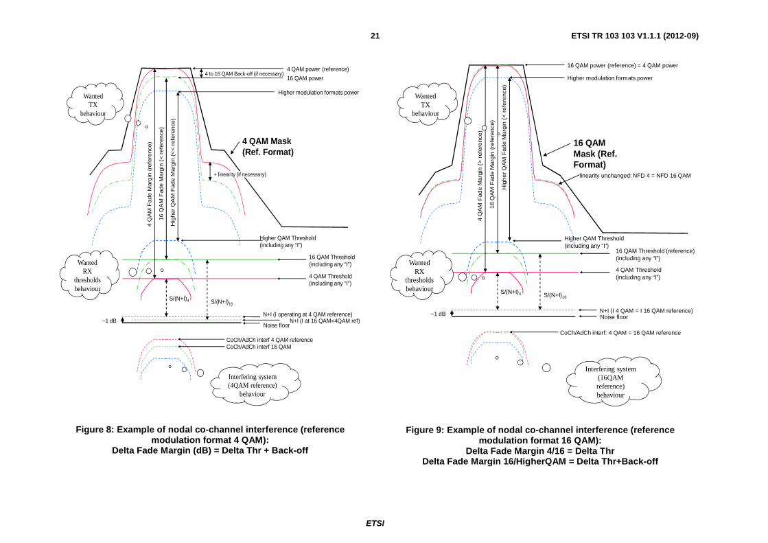
- Receiver sensitivity to interference of different modulation formats is not an issue in nodal PP links coordination (provided that noise figure is kept constant) because it is made on the basis of fixed channel separation and of a constant limited amount of interference (e.g. as defined in ECC/REC 01-05 [i.2] for "x" dB constant degradation of the noise floor on noise-limited links) from interfering channels into a fixed receiver bandwidth designed for that radio frequency channel. Therefore, whichever is the system mode of the receiver, the originally planned threshold degradation for the Reference mode will remain unchanged for all modes (see figures 8 and 9).
2) In some cases and for some valuable bands, administrations might require a minimum spectral efficiency (e.g. minimum 16 states formats).
3) The use of Mixed mode over a link coordinated in a specific Reference mode may often be considered as "best effort" operation; this is the quickest, simplest and effective way to coordinate links, unless administrations wish to consider in more detail the specific needs of mixed mode systems for exploiting all operating modes other than the reference one as described e.g. in clauses 4.1.3.2 and 4.1.3.3.
4) In some cases, the national administrative policy might foresee licensing fees depending also on the carried payload.
For suitably responding to these constraints, while leaving operative flexibility to the operator, the mixed-mode system and, when appropriate, bandwidth adaptive systems operations , safely deployed in general coordinated networks, may:
• Be licensed (i.e. in term of system and link parameters), in a fixed width radio frequency channel, for the format and capacity identified by the Reference mode (system type), with the desired "reference availability objective" (i.e. the typical 99,99 % or any other generally used by the administration concerned for the frequency coordination).
• Consider the fact that actual RSL thresholds for "dynamic" transitions among different modes of operation are defined as appropriate, by manufacturer or operators, independently from the "static" RSL of the BER thresholds defined in EN 302 217-2-2 [i.5] for the assessment of Article 3.2 of the R&TTE [i.1]. Only the "static" threshold of the reference mode is considered relevant for coordination and licensing process; in addition, once activated in "dynamic" operation, this threshold might no longer be reached due to earlier down shift to lower modulation format, see figure 4. In such case, these lower formats could be excluded from dynamic operation, or, when their higher availability is also desired, some "extra margin" on the link for compensating the effect might be recovered by planning the link for an even higher reference mode than that initially assumed for matching the desired minimum link capacity with required availability.
• Be left free, by licensing conditions, of using more complex formats and higher capacity, provided that they do not exceed the "Reference mode" spectral emission, in term of both output power density and spectrum mask (e.g. as in the 4 QAM "reference format" example shown in figure 8) (see note).
• Be left free, by licensing conditions, of using less complex formats and lower capacity, provided that they do not exceed the "Reference mode" spectral emission, in term of spectrum mask and output power density (e.g. as in the 16 QAM "reference format" example shown in figure 9) (see note).
• Preventively agree, with the administration concerned, license fee implication, if any, related to variable payload capacity.

ETSI
ETSI TR 103 103 V1.1.1 (2012-09) 20
• Mixed-mode systems should also respect additional requirements deriving from the dynamic change of modulation order (see clause 4.2.7 of EN 302 217-2-2 [i.5]).
• In mixed-mode operation, the RSL thresholds for transitions among different modes of operation are defined as appropriate by manufacturer or operators independently from the BER thresholds defined in clause 4.2.2 for the assessment of Article 3.2 of the R&TTE [i.1], see figures 3 and 4.
• When bandwidth adaptive systems are concerned, be coordinated with their reference mode corresponding to maximum bandwidth occupancy and its relevant lowest availability objective.
NOTE: The further possibility during ATPC operation of using the overdrive power conditions, described in clause 4.1.2, standing its critical applicability, is not considered of general use and, if still desired, is left for specific study by national administrations.
6 Impact on Article 3.2 "essential" parameters and operating conditions
From the discussion in previous clauses, for being capable of responding to the above mentioned licensing constraints, the introduction of mixed-mode (adaptive) systems within the frame of EN 302 217-2-2 [i.5] needed a specific set of parameters related to R&TTE [i.1] Article 3.2 "essential requirements".
These requirements may be summarized as follows:
1) As for any multirate/multiformat equipment, in the scope of EN 302 217-2-2 [i.5], mixed-mode systems should demonstrate of being capable of respecting all requirements for each of the rate/format offered (i.e. mixed-mode systems are tested as preset-mode systems). In this way it is ensured that the any selected "Reference mode" (equipment class) can be singularly satisfied (see note).
2) A specific set of presettings in term of matching payload capacity, modulation format and transmit power (including RTPC/ATPC operations, see also note in clause 4.1) is defined and assessed so that, within a licensed constant channel bandwidth and whichever is the instantaneously used mode (format), the TX spectrum mask, will not exceed that of the "Reference-mode" equipment class, as defined in EN 302 217-2-2 [i.5], among any possibly declared ones (which will be used for the link-by-link frequency coordination/licensing process) (see note).
3) Ensure that requirement 2) above is respected also during dynamic transitions between different modes. A specific requirement and conformance test has been introduced.
4) Bandwidth adaptive systems should be capable of respecting all requirements for the corresponding maximum bandwidth, which will define the "reference mode" (or multiple "reference modes" when more than one basic licensed channel size may be pre-set by the equipment).
NOTE: According requirement 2), mixed-mode systems, when in operation, do not need to meet all spectrum mask requirements in 1), which are tested for R&TTE [i.1] Article 3.2 conformance purpose only; from the technical co-ordination point of view, only that of the "Reference-mode" equipment class should be respected. Licensing fees, possibly related to system capacity, are not in the scope of the present document, but are responsibility of national administrations.
ETSI
ETSI TR 103 103 V1.1.1 (2012-09) 21
CoCh/AdCh interf 4 QAM referenceCoCh/AdCh interf 16 QAM
Noise floor
N+I (I operating at 4 QAM reference)~1 dB
S/(N+I)4
4 QAM Threshold(including any “I”)
16 QAM Threshold(including any “I”)
16
QA
M F
ade M
arg
in (
< r
efe
rence
)
4 Q
AM
Fade M
arg
in (
refe
rence
)
S/(N+I)16
16 QAM power
4 QAM power (reference)4 to 16 QAM Back-off (if necessary)
+ linearity (if necessary)
N+I (I at 16 QAM<4QAM ref)
4 QAM Mask (Ref. Format)
Higher modulation formats power
Higher QAM Threshold(including any “I”)
Hig
her
QA
M F
ade M
arg
in (
<<
refe
rence
)
Wanted TX
behaviour
Wanted RX
thresholds behaviour
Interfering system (4QAM reference)
behaviour
Figure 8: Example of nodal co-channel interference (reference modulation format 4 QAM):
Delta Fade Margin (dB) = Delta Thr + Back-off
CoCh/AdCh interf: 4 QAM = 16 QAM reference
Noise floorN+I (I 4 QAM = I 16 QAM reference)~1 dB
S/(N+I)4
4 QAM Threshold (including any “I”)
16 QAM Threshold (reference)(including any “I”)
16
QA
M F
ade
Ma
rgin
(re
fere
nce
)
4 Q
AM
Fa
de M
arg
in (
> r
efe
renc
e)
S/(N+I)16
16 QAM power (reference) = 4 QAM power
linearity unchanged: NFD 4 = NFD 16 QAM
16 QAM Mask (Ref. Format)
Higher modulation formats power
Higher QAM Threshold(including any “I”)
Hig
her
QA
M F
ade
Ma
rgin
(<
ref
ere
nce
)
Wanted TX
behaviour
Wanted RX
thresholds behaviour
Interfering system (16QAM reference) behaviour
Figure 9: Example of nodal co-channel interference (reference modulation format 16 QAM):
Delta Fade Margin 4/16 = Delta Thr Delta Fade Margin 16/HigherQAM = Delta Thr+Back-off

ETSI
ETSI TR 103 103 V1.1.1 (2012-09) 22
History
Document history
V1.1.1 September 2012 Publication