TR 103 263 - V1.1.1 - Electromagnetic compatibility and Radio spectrum …€¦ · ·...
41
ETSI TR 103 263 V1.1.1 (2014-07) Electromagnetic compatibility and Radio spectrum Matters (ERM); System Reference document (SRdoc); Cognitive radio techniques for Satellite Communications operating in Ka band TECHNICAL REPORT
Transcript of TR 103 263 - V1.1.1 - Electromagnetic compatibility and Radio spectrum …€¦ · ·...

ETSI TR 103 263 V1.1.1 (2014-07)
Electromagnetic compatibility and Radio spectrum Matters (ERM);
System Reference document (SRdoc); Cognitive radio techniques for
Satellite Communications operating in Ka band
TECHNICAL REPORT

ETSI
ETSI TR 103 263 V1.1.1 (2014-07) 2
Reference DTR/ERM-513
Keywords radio, satellite, spectral management, SRdoc,
system, terrestrial
ETSI
650 Route des Lucioles F-06921 Sophia Antipolis Cedex - FRANCE
Tel.: +33 4 92 94 42 00 Fax: +33 4 93 65 47 16
Siret N° 348 623 562 00017 - NAF 742 C
Association à but non lucratif enregistrée à la Sous-Préfecture de Grasse (06) N° 7803/88
Important notice
The present document can be downloaded from: http://www.etsi.org
The present document may be made available in electronic versions and/or in print. The content of any electronic and/or print versions of the present document shall not be modified without the prior written authorization of ETSI. In case of any
existing or perceived difference in contents between such versions and/or in print, the only prevailing document is the print of the Portable Document Format (PDF) version kept on a specific network drive within ETSI Secretariat.
Users of the present document should be aware that the document may be subject to revision or change of status. Information on the current status of this and other ETSI documents is available at
http://portal.etsi.org/tb/status/status.asp
If you find errors in the present document, please send your comment to one of the following services: http://portal.etsi.org/chaircor/ETSI_support.asp
Copyright Notification
No part may be reproduced or utilized in any form or by any means, electronic or mechanical, including photocopying and microfilm except as authorized by written permission of ETSI.
The content of the PDF version shall not be modified without the written authorization of ETSI. The copyright and the foregoing restriction extend to reproduction in all media.
© European Telecommunications Standards Institute 2014.
All rights reserved.
DECTTM, PLUGTESTSTM, UMTSTM and the ETSI logo are Trade Marks of ETSI registered for the benefit of its Members. 3GPPTM and LTE™ are Trade Marks of ETSI registered for the benefit of its Members and
of the 3GPP Organizational Partners. GSM® and the GSM logo are Trade Marks registered and owned by the GSM Association.

ETSI
ETSI TR 103 263 V1.1.1 (2014-07) 3
Contents
Intellectual Property Rights ................................................................................................................................ 5
Foreword ............................................................................................................................................................. 5
Modal verbs terminology .................................................................................................................................... 5
Executive summary ............................................................................................................................................ 5
Introduction ........................................................................................................................................................ 5
1 Scope ........................................................................................................................................................ 7
2 References ................................................................................................................................................ 7
2.1 Normative references ......................................................................................................................................... 7
2.2 Informative references ........................................................................................................................................ 7
3 Definitions, symbols and abbreviations ................................................................................................. 10
3.1 Definitions ........................................................................................................................................................ 10
3.2 Symbols ............................................................................................................................................................ 10
3.3 Abbreviations ................................................................................................................................................... 10
4 Comments on the System Reference document ..................................................................................... 11
4.1 Statements by ETSI Members .......................................................................................................................... 12
5 Presentation of the system or technology ............................................................................................... 12
6 Market information................................................................................................................................. 12
7 Technical information ............................................................................................................................ 16
7.1 Detailed technical description .......................................................................................................................... 16
7.1.1 Principles of cognitive radio techniques for SatCom operating in Ka band ............................................... 20
7.2 Technical parameters and implications on spectrum ........................................................................................ 22
7.2.1 Status of technical parameters .................................................................................................................... 22
7.2.1.1 Current ITU and European Common Allocations ................................................................................. 22
7.2.1.2 Sharing and compatibility studies (if any) already available ................................................................ 27
7.2.1.3 Sharing and compatibility issues still to be considered ......................................................................... 30
7.2.2 Transmitter parameters ............................................................................................................................... 32
7.2.2.1 FSS earth stations .................................................................................................................................. 32
7.2.2.1.1 Transmitter Output Power / Radiated Power ................................................................................... 32
7.2.2.1.2 Antenna Characteristics ................................................................................................................... 33
7.2.2.1.3 Operating Frequency ....................................................................................................................... 33
7.2.2.1.4 Bandwidth ....................................................................................................................................... 33
7.2.2.1.5 Unwanted emissions ........................................................................................................................ 33
7.2.2.2 BSS earth stations ................................................................................................................................. 33
7.2.2.2.1 Transmitter Output Power / Radiated Power ................................................................................... 33
7.2.2.2.2 Antenna Characteristics ................................................................................................................... 34
7.2.2.2.3 Operating Frequency ....................................................................................................................... 34
7.2.2.2.4 Bandwidth ....................................................................................................................................... 34
7.2.2.2.5 Unwanted emissions ........................................................................................................................ 34
7.2.2.3 FS stations ............................................................................................................................................. 35
7.2.2.3.1 Transmitter Output Power / Radiated Power ................................................................................... 35
7.2.2.3.2 Antenna Characteristics ................................................................................................................... 35
7.2.2.3.3 Operating Frequency ....................................................................................................................... 35
7.2.2.3.4 Bandwidth ....................................................................................................................................... 35
7.2.2.3.5 Unwanted emissions ........................................................................................................................ 35
7.2.3 Receiver parameters .................................................................................................................................... 35
7.2.3.1 FSS earth stations .................................................................................................................................. 35
7.2.3.2 BSS earth stations ................................................................................................................................. 35
7.2.3.3 FS stations ............................................................................................................................................. 36
7.2.4 Channel access parameters ......................................................................................................................... 36
7.2.4.1 FSS earth stations .................................................................................................................................. 36

ETSI
ETSI TR 103 263 V1.1.1 (2014-07) 4
7.2.4.2 BSS earth stations ................................................................................................................................. 36
7.2.4.3 FS stations ............................................................................................................................................. 36
7.3 Information on relevant standard(s) ................................................................................................................. 36
8 Radio spectrum request and justification ............................................................................................... 37
9 Regulations ............................................................................................................................................. 37
9.1 Uncoordinated FSS Earth Stations 9.1 Current regulations ............................................................................. 37
9.2 Proposed regulation and justification ............................................................................................................... 38
9.2.1 FSS reception .............................................................................................................................................. 38
9.2.2 FSS transmission ........................................................................................................................................ 39
Annex A (informative): Bibliography ........................................................................................................... 40
History .............................................................................................................................................................. 41

ETSI
ETSI TR 103 263 V1.1.1 (2014-07) 5
Intellectual Property Rights IPRs essential or potentially essential to the present document may have been declared to ETSI. The information pertaining to these essential IPRs, if any, is publicly available for ETSI members and non-members, and can be found in ETSI SR 000 314: "Intellectual Property Rights (IPRs); Essential, or potentially Essential, IPRs notified to ETSI in respect of ETSI standards", which is available from the ETSI Secretariat. Latest updates are available on the ETSI Web server (http://ipr.etsi.org).
Pursuant to the ETSI IPR Policy, no investigation, including IPR searches, has been carried out by ETSI. No guarantee can be given as to the existence of other IPRs not referenced in ETSI SR 000 314 (or the updates on the ETSI Web server) which are, or may be, or may become, essential to the present document.
Foreword This Technical Report (TR) has been produced by ETSI Technical Committee Electromagnetic compatibility and Radio spectrum Matters (ERM).
Modal verbs terminology In the present document "shall", "shall not", "should", "should not", "may", "may not", "need", "need not", "will", "will not", "can" and "cannot" are to be interpreted as described in clause 3.2 of the ETSI Drafting Rules (Verbal forms for the expression of provisions).
"must" and "must not" are NOT allowed in ETSI deliverables except when used in direct citation.
Executive summary As the Internet traffic grows, Broadband satellite systems have to increase their capacity. Beyond space segment performance upgrade, additional spectrum is needed. Ka band is the preferred frequency band for such network. It includes exclusive spectrum allocation to FSS as well as spectrum shared between FSS and other services among which FS or FSS feeder links for BSS.
Until now, the risk associated to the use of these shared bands may have discouraged its full exploitation by satellite systems.
Cognitive radio techniques may help to minimize this risk under appropriate operational and regulatory conditions.
The present document provides an overview of typical Broadband Satellite systems targeting the Ka band shared between FSS and other services, the related market data and spectrum regulation context.
It then analyses the co-existence scenarios of FSS with FS or FSS feeder links for BSS, the enabling Cognitive Radio techniques as well as operational and regulatory conditions for a safer use of the shared spectrum.
Introduction The present document has been developed to support the co-operation between ETSI and the Electronic Communications Committee (ECC) of the European Conference of Post and Telecommunications Administrations (CEPT).
Flexible spectrum utilization is a surging trend for the optimized exploitation of spectrum resources, and the cognitive approach has already demonstrated its potential for terrestrial systems, but not yet in the SatCom domain. However, SatCom are fundamental to achieve the challenging objectives of fast broadband access for everyone by 2020: their inherent large coverage footprint makes them the most suitable access scheme to reach those areas where deployment of wired and wireless networks is not economically viable.

ETSI
ETSI TR 103 263 V1.1.1 (2014-07) 6
The Cognitive Radio (CR) paradigm has been identified as a promising solution to conciliate the existing conflicts between spectrum demand growth and spectrum underutilization, and increase the overall efficiency of spectrum exploitation.
It is worth mentioning the 03-September-2012 Communication (2012) 478 [i.8] from the European Commission to the European Parliament, the Council, the European Economic and Social Committee and the Committee of the Regions on the promotion of the shared use of radio spectrum resources in the internal market. This communication provides clear guidance on the ways the technology research can help the compliance of the policy objectives.
Furthermore, in 2011, the Radio Spectrum Policy Group (European Commission) issued a Report on Collective Use of Spectrum that noted the high demand for shared use [i.1]. The RSPG stated that: "there is a need to progress further on appropriate regulatory mechanisms in regard to sharing of spectrum". The key challenge for National Radio Authorities is to find appropriate ways to authorize shared spectrum access to a band, i.e. to allow two or more users to use the same frequency range under a defined sharing arrangement.
This justifies the relevance of the present document that analyses the potential of CR concepts in satellite networks context, in order to improve coexistence scenarios in selected spectrum allocated to SatCom services. It has been largely drafted with the support of the EU funded project CoRaSat (see [i.2]).

ETSI
ETSI TR 103 263 V1.1.1 (2014-07) 7
1 Scope The present document identifies the potential regulatory impacts associated to the operation of SatCom solutions implementing cognitive radio techniques. In particular it addresses different scenarios in Ka band (17,3 GHz - 20,2 GHz for space to earth and 27,5 GHz - 30,0 GHz for earth to space) where the satellite communication service should not create any harmful interference to another incumbent whether terrestrial or satellite service entitled to use the same spectrum on a primary basis. It includes in particular:
• market information;
• technical information (including expected sharing and compatibility issues);
• regulatory issues.
The present document will also identify the additional ETSI standards that have to be created or changed for enabling this kind of architectures.
2 References References are either specific (identified by date of publication and/or edition number or version number) or non-specific. For specific references, only the cited version applies. For non-specific references, the latest version of the reference document (including any amendments) applies.
Referenced documents which are not found to be publicly available in the expected location might be found at http://docbox.etsi.org/Reference.
NOTE: While any hyperlinks included in this clause were valid at the time of publication, ETSI cannot guarantee their long term validity.
2.1 Normative references The following referenced documents are necessary for the application of the present document.
Not applicable .
2.2 Informative references The following referenced documents are not necessary for the application of the present document but they assist the user with regard to a particular subject area.
[i.1] Point Topic: "BB-MED TN3.1, Expected Broadband demand in 'ESA Study Countries' in 2020", March 2012.
[i.2] COM(2010) 245: "A Digital Agenda for Europe, European Communication", Brussels, 19.05.2010.
[i.3] ETSI EN 302 307 (V1.2.1): "Digital Video Broadcasting (DVB); Second generation framing structure, channel coding and modulation systems for Broadcasting, Interactive Services, News Gathering and other broadband satellite applications (DVB-S2)".
[i.4] ETSI TS 101 545-1 (V1.1.1): "Digital Video Broadcasting (DVB);Second Generation DVB Interactive Satellite System (DVB-RCS2);Part 1: Overview and System Level specification".
[i.5] ETSI EN 301 545-2 (V1.1.1): "Digital Video Broadcasting (DVB); Second Generation DVB Interactive Satellite System (DVB-RCS2); Part 2: Lower Layers for Satellite standard".
[i.6] ETSI TS 101 545-3 (V1.1.1): "Digital Video Broadcasting (DVB);Second Generation DVB Interactive Satellite System (DVB-RCS2); Part 3: Higher Layers Satellite Specification".

ETSI
ETSI TR 103 263 V1.1.1 (2014-07) 8
[i.7] BATS Project.
NOTE: Available at: http://www.batsproject.eu/.
[i.8] COM(2012) 478: "Communication from the Commission to the European Parliament, the Council, the European Economic and Social Committee and the Committee of the Regions. Promoting the shared use of radio spectrum resources in the internal market.
NOTE: Available at http://ec.europa.eu/information_society/policy/ecomm/radio_spectrum/_document_storage/com/com-ssa.pdf.
[i.9] ECC Report 152 (September 2010): "The use of the frequency bands 27.5-30.0 GHz and 17.3-20.2 GHz by satellite networks".
[i.10] Report Recommendation ITU-R SM.2152 (09/2009): "Definition of Software Defined Radio (SDR) and Cognitive Radio Systems (CRS)".
[i.11] ERC Report 099: "The analysis of the coexistence of two FW A cells in the 24.5-26.5 GHz and 27.5 - 29.5 GHz bands".
[i.12] ECC Report 32 (Oct 2003) "Mechanisms to improve co-existence of Multipoint (MP) systems".
[i.13] CEPT/ERC Report 25: "The European Table of Frequency Allocations and Utilisations Covering the Frequency Range 9 kHz to 275 GHz: Lisboan January 2002 - Dublin 2003 - Turkey 2004".
[i.14] ECC Report 76 (Feb 2006): "Cross-border coordination of multipoint fixed wireless systems in frequency bands from 3.4 GHz TO 33.4 GHz".
[i.15] Radio Regulations, ITU-Rs incorporated by reference, Edition of 2012.
[i.16] Recommendation ITU-R SF.1719: "Sharing between point-to-point and point-to-multipoint fixed service and transmitting earth stations of GSO and non-GSO FSS systems in the 27.5-29.5 GHz band".
[i.17] ETSI EN 301 459 (V1.3.1): "Satellite Earth Stations and Systems (SES); Harmonized EN for Satellite Interactive Terminals (SIT) and Satellite User Terminals (SUT) transmitting towards satellites in geostationary orbit in the 29,5 GHz to 30,0 GHz frequency bands covering essential requirements under article 3.2 of the R&TTE Directive".
[i.18] Recommendation ITU-R S.580: "Radiation diagrams for use as design objectives for antennas of earth stations operating with geostationary satellites".
[i.19] Recommendation ITU-R S.465: "Reference radiation pattern of earth station antennas in the fixed-satellite service for use in coordination and interference assessment in the frequency range from 2 to 31 GHz".
[i.20] Recommendation ITU-R F.758-5: "System parameters and considerations in the development of criteria for sharing or compatibility between digital fixed wireless systems in the fixed service and systems in other services and other sources of interference".
[i.21] ETSI TR 102 243: "Fixed Radio Systems; Representative values for transmitter power and antenna gain to support inter- and intra-compatibility and sharing analysis; Part 1: Digital point-to-point systems".
[i.22] Recommendation ITU-R F.699-7: "Reference radiation patterns for fixed wireless system antennas for use in coordination studies and interference assessment in the frequency range from 100 MHz to about 70 GHz".
[i.23] ERC/REC(01)03: "European Radiocommunications Committee (ERC) within the European Conference of Postal and Telecommunications Administrations (CEPT); ERC Recommendation (01)03; use of parts of the band 27.5-29.5 GHz for Fixed Wireless Access (FWA)".

ETSI
ETSI TR 103 263 V1.1.1 (2014-07) 9
[i.24] ETSI EN 302 217-2-2: "Fixed Radio Systems; Characteristics and requirements for point-to-point equipment and antennas; Part 2-2: Digital systems operating in frequency bands where frequency co-ordination is applied; Harmonized EN covering the essential requirements of article 3.2 of the R&TTE Directive".
[i.25] ETSI EN 303 978: "Satellite Earth Stations and Systems (SES); Harmonized EN for Earth Stations on Mobile Platforms (ESOMP) transmitting towards satellites in geostationary orbit in the 27,5 GHz to 30,0 GHz frequency bands covering the essential requirements of article 3.2 of the R&TTE Directive".
[i.26] ETSI EN 301 360: "Satellite Earth Stations and Systems (SES); Harmonized EN for Satellite Interactive Terminals (SIT) and Satellite User Terminals (SUT) transmitting towards geostationary satellites in the 27,5 GHz to 29,5 GHz frequency bands covering essential requirements under article 3.2 of the R&TTE Directive".
[i.27] ETSI EN 301 359: "Satellite Earth Stations and Systems (SES); Satellite Interactive Terminals (SIT) using satellites in geostationary orbit operating in the 11 GHz to 12 GHz (space-to-earth) and 29,5 GHz to 30,0 GHz (earth-to-space) frequency bands".
[i.28] ETSI EN 301 358: "Satellite Earth Stations and Systems (SES); Satellite User Terminals (SUT) using satellites in geostationary orbit operating in the 19,7 GHz to 20,2 GHz (space-to-earth) and 29,5 GHz to 30 GHz (earth-to-space) frequency bands".
[i.29] ERC/DEC(00)07: "ERC Decision of 19 October 2000 on the shared use of the band 17.7 - 19.7 GHz by the fixed service and Earth stations of the fixed-satellite service (space-to-Earth)".
[i.30] CEPT Decision ECC/DEC/(05)01: "The use of the band 27.5-29.5 GHz by the Fixed Service and uncoordinated Earth stations of the Fixed-Satellite Service (Earth-to-space)".
[i.31] ECC/DEC(05)08: "The availability of frequency bands for high density applications in the Fixed-Satellite Service (space-to-Earth and Earth-to-space)".
[i.32] ECC Report 184: "The Use of Earth Stations on Mobile Platforms Operating with GSO Satellite Networks in the Frequency Range 17.3-20.2 GHz and 27.5-30.0 GHz".
[i.33] ERC Recommendation T/R 13-02: "Preferred channel arrangements for fixed service systems in the frequency range 22.0 - 29.5 GHz".
[i.34] ECC Report 198 (May 2013): "Adaptive modulation and ATPC operations in fixed point-to-point systems - Guideline on coordination procedures".
[i.35] ECC FM(13)126 (6 August 2013): "Summary of the WGFM Questionnaire on the 17.7-19.7 GHz Fixed Service".
[i.36] ECC FM44(11)039rev2 (1 November 2011): "Questionnaire to administrations on the FS use of the 28.8365-28.9485 GHz band".
[i.37] ECC Report 173 (04/04/2012): "Fixed Service in Europe".
[i.38] Recommendation ITU-R F.1245-2: "Mathematical model of average and related radiation patterns for line-of-sight point-to-point fixed wireless system antennas for use in certain coordination studies and interference assessment in the frequency range from 1 GHz to about 70 GHz".
[i.39] "Demography report 2010", March 2011, Eurostat, ©European Union.
[i.40] CEPT, FM44: "Responses of FS use of 28 GHz".
NOTE: Available at: Responses of FS use of 28 GHz.
[i.41] Decision D-OCG 21/3.

ETSI
ETSI TR 103 263 V1.1.1 (2014-07) 10
3 Definitions, symbols and abbreviations Where possible, definitions from the ITU Radio Regulations [i.15] should be used. If there is not a definition in the ITU Radio Regulations [i.15], wherever possible, existing definitions in the ETSI TEDDI should be used rather than creating new ones (see Decision D-OCG 21/3 [i.41]).
3.1 Definitions For the purposes of the present document, the following terms and definitions apply:
centralized reference database: structured set of records which describe the RF transmitters characteristics of the incumbent and the cognitive radio systems
EXAMPLE: Geographical location, frequency band, EIRP, bandwidth, azimuth/elevation of the main lobe.
Cognitive Radio System (CRS): employing technology that allows the system to obtain knowledge of its operational and geographical environment, established policies and its internal state; to dynamically and autonomously adjust its operational parameters and protocols according to its obtained knowledge in order to achieve predefined objectives; and to learn from the results obtained Report Recommendation ITU-R SM.2152 [i.10].
frequency sharing: sharing of a frequency band between incumbent and cognitive systems
incumbent system: system already deployed and operating in a given frequency band
spectrum sensing: mechanism which characterizes the usage of a frequency band by incumbent systems
EXAMPLE: Time slot, geographical area, frequency carrier, RF power, channel bandwidth, etc.
3.2 Symbols For the purposes of the present document, the following symbols apply:
f Frequency P Power R Distance t Time
3.3 Abbreviations For the purposes of the present document, the following abbreviations apply:
ACP Adjacent channel power ASI Adjacent Satellite Interference BATS Broadband Access via integrated Terrestrial & Satellite systems BB-MED BroadBand Mediterranean Development BFWA Broadband Fixed Wireless Access BSS Broadcast Satellite Service BUC Block Up Converters CEPT Conférence Européenne des administrations des Postes et Télécommunications CR Cognitive Radio dB deciBel dBi decibel relative to an isotropic radiator DVB-RCS2 Digital Video Broadcasting - Return Channel via Satellite - 2nd Generation DVB-S Digital Video Broadcasting - Satellite DVB-S2 Digital Video Broadcasting - Satellite - Second Generation EC European Community ECC Electronic Communications Committee ECO European Communications Office EFIS ECO Frequency Information System (European Spectrum Information Portal) EG ETSI Guide

ETSI
ETSI TR 103 263 V1.1.1 (2014-07) 11
EIRP Effective Isotropic Radiated Power ERC European Radiocommunications Committee ESOMP Earth Station On Mobile Platform EU European Union FM Frequency Management FS Fixed Service FSS Fixed Satellite Service GSO GeoSynchronous Orbit GW GateWay HD High Definition HDFSS High Density Fixed Satellite Service HEST High EIRP Satellite Terminals HPA High Power Amplifier IC Interference Cartography ISSN International Standard Serial Number ITU International Telecommunication Union ITU-R International Telecommunication Union – Radio Sector KPI Key Performance Indicator LEST Low EIRP Satellite Terminals LNB Low Noise Block MF-TDMA Multi-Frequency - Time Division Multiple Access MS Mobile Service MSS Mobile Satellite Service MWS Multimedia Wireless Systems NCC Network Control Centre P2M Point To Multi point P2P Point To Point PC Power Control PT Project Team QoS Quality of Service QPSK Quadrature Phase Shift Keying REM Radio Environment Map RF Radio Frequency RR Radio Regulation RSPG Radio Spectrum Policy Group SCC Satellite Control Centre SCN Satellite Communications and Navigation SD Standard Definition SIT Satellite Interactive Terminal SME Small Medium Entreprise SPD Spectral Power Density SRR Short Range Radar SUT Satellite User Terminal TC-ERM Technical Committee EMC and Radio Spectrum Matter TC-SES Technical Committee Satellite Earth Stations and Systems TDM Time Division Multipling TDMA Time Division Multiple Access TM Transmission Mask TTC Telemetry, Tracking & Control UK United Kingdom UT User Terminal WGFM Working Group Frequency Management
4 Comments on the System Reference document No ETSI members raised any comments.

ETSI
ETSI TR 103 263 V1.1.1 (2014-07) 12
4.1 Statements by ETSI Members This version is preliminary. ETSI seeks guidances/feedbacks from CEPT on its content.
5 Presentation of the system or technology This clause entails high level information such as system description, applications, new technology (if any).
The system scenario refers to the deployment of FSS earth stations in non exclusive Ka frequency band.
It implies the coexistence of a cognitive FSS system together with incumbent systems among which FS or BSS.
The FSS system is assumed to be a geo-satellite system offering broad or multi-spot beam coverage with a frequency re-use scheme. The FSS system is described further in subsequent clause.
6 Market information The following is extracted from the D2.2 "Broadband Technologies, Capabilities & Challenges" produced by the BATS project [i.7].
"Point Topic produced, within the framework of the European Space Agency's project "BB-MED TN3.1, Expected Broadband demand in 'ESA Study Countries' in 2020", the broadband demand is forecast per country by 2020. Note that this study focused on commercial deployment of broadband; public support was considered separately. One of the key results of this study is that over a 20 % of premises in the current EU27 will either not be covered by or will not take-up a superfast broadband connection (i.e. > 30 Mbps) by 2020."
Figure 1 illustrates the superfast broadband gaps in the EU27 countries by 2020 considering both, the unavailability and the lack of take-up. Note that in many European regions more than the 50 % of households will not subscribe to or lack availability to superfast broadband.

Figure 1: Superfast broadb
Figure 2 shows the percentage of households broadband speeds above 30 Mbps by 2020. Dand the United Kingdom will be leading in tersuggests that countries especially in the Easteobjectives of the Digital Agenda without publ
ETSI
ETSI TR 103 2613
dband gaps predicted for 2020 in EU27 countries
ds in the EU27 countries and Turkey which predicted to ha. Densely populated countries like Belgium, Malta, the Neterms of superfast broadband availability. On the other ha
stern Europe and the Mediterranean will be still far from aublic intervention. Very few countries will exceed 90 % av
263 V1.1.1 (2014-07)
es [i.1]
have access to Netherlands, Sweden hand, the study achieving the
availability.

ETSI
ETSI TR 103 263 V1.1.1 (2014-07) 14
Figure 2: Superfast Broadband Availability by 2020 [i.1]
Figure 3 illustrates the take-up of superfast broadband in the same subset of countries. In other words, it illustrates the percentage of the total number of households in each country which will subscribe to superfast broadband by 2020. From the study data, we can establish that on average superfast broadband will be available to the 67,8 % of households but only the 53,8 % will take up the service.
Figure 3: Superfast Broadband Take-up Penetration by 2020 [i.1]

ETSI
ETSI TR 103 263 V1.1.1 (2014-07) 15
Looking more in detail to satellite broadband service provision, figure 4 shows its addressable market (blue bars) and take-up percentage (red bars) by 2020 as established in [i.1]. In other words, it shows the percentage of households covered by satellite outside fixed and LTE intersection, and the percentage of premises which will subscribe to satellite broadband services. The study states that, in average, the 14,4 % of households in E27 and Turkey will have satellite as the only available technology for contracting broadband services. However, the average percentage of total households which will take up a satellite broadband connection is the 3,72 %, which are mostly located in remote areas.
Assuming 500 M of inhabitants in the Europe Union and an average of 2,4 inhabitants per house holds [i.39], the satellite broadband market potential corresponds to up to ~7,7 M households in Europe and Turkey in un served areas and partly in underserved areas.
Assuming an average number of 1 Million subscribers served per high throughput satellite operating in Ka band and delivering broadband access, the market represents in Europe a potential of several satellites to meet the Digital Agenda policy objective [i.2] that seeks to ensure that, by 2020, all Europeans have access to higher internet speeds of above 30 Mbps (peak rates).
Figure 4: Satellite broadband addressable market (blue) and take-up penetration (red) by 2020
In view of this above market potential and considering the increasing bandwidth demand, there is strong interest to access extra spectrum including the chunks shared with other services. This justifies the need to explore Cognitive radio techniques in SatCom context to allow the exploitation of these shared frequency band with minimum risk of interference.
Furthermore, cognitive radio techniques are expected to have a high potential market since they can be used to alleviate some of the interferences experienced in exclusive FSS allocation:
• Cross Pol (Xpol) Interference.
• Adjacent Satellite Interference (ASI).
• Terrestrial Interference - FS to FSS.
• Earth station interference - Uplink feeder link to FSS.
• Interference to incumber users 1. - FSS to FS.
• Interference to incumber users 2. - FSS to BSS feeder link stations.

ETSI
ETSI TR 103 263 V1.1.1 (2014-07) 16
• Deliberate Interference (Jamming).
Cross Pol (Xpol) Interference: This type of interference is usually caused by incompatible modulation types transmitted in the orthogonal polarization field; poorly aligned antennas; and lack of training/experience of the uplink operators. It is extremely time consuming and labor intensive in both equipment and training. Due to its nature it is expected that Cognitive Radio will provide here only limited benefits.
ASI - Adjacent Satellite Interference: This type of interference is generally accidental, due to operator error, or poor inter-system coordination. Frequently, this can be resolved between the satellite operators. Unfortunately, this type of interference is becoming more prevalent as two degree spacing between satellites in the geostationary arc becomes more common. One main action to minimize is the provision of substantial training session of the installers and the operators. Separately the impacted satellites operators have to validate their EIRP settings to adhere to the specific allowed max. levels. As another main action, the provision of additional options to access further spectrum provided by future Cognitive Radio is understood to be a basis of substantial additional value.
Terrestrial Interference - FS to FSS: This type of interference often caused by terrestrial services to the fixed satellite services is different for the frequency bands, the interference type and highly dependent on the geographic region and the applicable regulatory framework being enforced. It is seen as a very important application for Cognitive Radio solutions with its potential application of dynamic adaptation measures to enhance the availability of satellite transmissions.
Earth station interference - Uplink feeder link to FSS: The feeder link uplink Earth stations (incumbent users) may cause harmful interference to cognitive FSS users in the shared frequency bands.
Interference to incumber users 1. - FSS to FS: The cognitive FSS users may cause harmful interference to FS services in the shared frequency bands. The FS receiver towers (terrestrial link stations) may receive the FSS signal using the same frequency band and under the usage of the shared common bands.
Interference to incumber users 2. - FSS to BSS feeder link stations: The cognitive FSS users may cause harmful interference to incumbent users of the bands used by BSS feeder link stations, received by the satellite on this incumbent network and be received as harmful interference by the users of the BSS feeder link network on the downlink.
Deliberate Interference: This sporadic type of interference is usually geopolitically motivated. It is, generally, relatively easy to locate, but almost impossible to remove without political intervention, which can prove difficult.
7 Technical information ETSI members making comments should endeavour to reach consensus amongst themselves, to minimize the number of comments. If consensus cannot be reached on a clause, then it is divided into two sections: one for the proponents and one for comments on the text of the proponents. Such statements should be clearly attributable to the ETSI member(s) making these statements.
7.1 Detailed technical description The system analysed in this clause refers to a satellite network operating in the Ka band and providing broadband access to user terminals. It supports a wide range of services among which Internet services (email, file sharing, P2P, P2M, voice and video-conferencing, video download or streaming in SD, HD or 3D format), backhaul services as well as telehealth, elearning and ecommerce and remote monitoring services.
Such network is typically addressing user terminals:
• fixed terminals on the roof of a residential home or a SME premises in rural or remote areas;
• mobile terminals on a mobile platforms such as trains, vessels or aircrafts.

ETSI
ETSI TR 103 263 V1.1.1 (2014-07) 17
The satellite network provides connectivity between the user terminals and anchor gateways, which are also connected to the Public Internet. An anchor gateway can typically serve up to ten thousands of user terminals (professional market) or up to hundred thousand of terminals (consumer market) in a star topology. The system's geostationary satellite also named "high throughput satellite" typically generates between several tens and several hundred beams to achieve high transmission and reception gains towards the user terminals distributed across its service area. Multi beam coverage allows to implement a frequency re-use scheme which allocate a given frequency band and polarization to a "group" of non-adjacent beams. Typically a frequency re-use factor of 4 is adopted in such multibeam satellite network.
Figure 5: Illustration of a frequency re-use pattern in a multi beam satellite (reuse factor 4)
In oder to accompany the ever increasing demand for bandwidth and cost per Mbps reduction, the satellite throughput has to be maximized. This can be achieved by:
• Reduce the beam width, typically well below 0,3°.
• Increase the frequency band allocated per beam, by using for example non exclusive FSS frequency bands that are shared between FSS and other services (e.g. FS or BSS in this system scenario).
• Efficient waveforms robust towards signal degradation thanks to interference mitigation techniques including ground-based signal processing.
In the document, we assume that the satellite network is based on state of the art radio interfaces, such as:
• Forward link: TDM based DVB-S2 [i.3] and its upcoming evolution DVB-Sx.
• Return link: MF-TDMA based DVB-RCS2 [i.4], [i.5] and [i.6].
(or similar radio interfaces, which operate in a comparable manner and have similar functionality but could use proprietary air interface technologies.)

ETSI
ETSI TR 103 263 V1.1.1 (2014-07) 18
Figure 6: Overall satellite network architecture
As depicted above, the system encompasses:
• A space segment composed by at least one geostationary satellite. Each satellite allows to establish bi-directional links between a set of gateways (GW) and the user terminals, thanks to a set of feeder and user beams.
• A ground segment which includes:
- A set of anchor gateways which are in charge of transmitting and receiving data, control and management traffic to or from the user terminals.
- A Telemetry Tracking and Control (TTC) station to transmit and receive information to or from the space segment.
- A Satellite Control Center (SCC) which aims at monitoring and controlling the space segment.
- A Network Control Center (NCC) in charge of managing the set of gateways.
• A user segment which is composed of a set of user terminals. The user terminal is connected to a local area network in order to deliver the useful traffic to the end user. Each terminal includes a reception and a transmission RF chains. The size of the terminal dish is typically 75 cm, while its power ranges between 2 and 4 W.
The network connecting the anchor GWs and the user terminals follows a star topology. A backbone network, which is not part of the access network, is in charge of interconnecting the SCC, the NCC, the GWs, the TTC and the Internet Service Providers (ISPs), namely to convey management and control traffics.
A forward (respectively return) link is divided into a feeder (respectively a user) uplink and a user (respectively a feeder) downlink.
We consider 2 possible frequency plans based on a 4 color scheme.
Backbone GW
Backbone GW
SCC
GW1
NCC
ISP1
ISP2
NCC : Network Control CenterSCC : Satellite Control CenterISP : Internet Service ProviderTTC : Telemetry, Tracking & Control
TTC

ETSI
ETSI TR 103 263 V1.1.1 (2014-07) 19
A nominal frequency plan is illustrated in figure 7:
• The user downlink is assigned the exclusive FSS band (namely [19,7 - 20,2] GHz) and a portion of the Ka-band spectrum primarily shared with BSS (namely [17,3 - 17,7] GHz) and FS (namely [17,7 - 19,7] GHz). Thus the frequency plan assigned to the user downlink features 2,9 GHz of spectrum on two orthogonal circular polarization. This corresponds to a 1,4 GHz spectrum allocation per beam, according to a regular four-color scheme (including a frequency guard band between 18,7 GHz and 18,8 GHz). This enables an "increase" of the useful spectrum by 5,6 (= 1,4 / 0,25 GHz) with respect to systems operating in the exclusive FSS band only.
• Regarding the user uplink, the system uses the exclusive FSS band (namely [29,5 - 30] GHz) as well as the band [27,5 - 29,5] GHz shared with FS. Thus the frequency plan assigned to the user downlink features 2,5 GHz of spectrum on two orthogonal circular polarization. This corresponds to a 1,25 GHz spectrum allocation per beam, according to a regular four-color scheme. This enables an "increase" of the useful spectrum by 5 (= 1,25 / 0,25 GHz) with respect to systems operating in the exclusive FSS band only.
Figure 7: Nominal frequency plan for the FSS satellite system
An alternative frequency plan illustrated in figure 8:
• The user downlink is assigned the exclusive FSS band (namely [19,7 - 20,2] GHz) but also a portion of the Ka-band spectrum primarily shared with BSS (namely [17,3 - 17,7] GHz) and FS (namely [17,7 - 19,7] GHz). Thus the frequency plan assigned to the user downlink features 2,9 GHz of spectrum on two orthogonal circular polarization. This corresponds to a 1,4 GHz spectrum allocation per beam, according to a regular four-color scheme (including a frequency guard band between 18,7 GHz and 18,8 GHz). This enables an "increase" of the useful spectrum by 5,6 (= 1,4/0,25 GHz) with respect to systems operating in the exclusive FSS band only.
• Regarding the user uplink, the system uses the exclusive FSS band (namely [29,5 - 30] GHz) as well as the band [28,4465 - 28,9465] GHz shared with FS. Thus the frequency plan assigned to the user downlink features 1 GHz of spectrum on two orthogonal circular polarization. This corresponds to a 500 MHz spectrum allocation per beam, according to a regular four-color scheme. This enables an "increase" of the useful spectrum by 2 (= 1 / 0,5 GHz) with respect to systems operating in the exclusive FSS band only.
LHCP
RHCP
LHCP
RHCP
27.5 30.0 GHz29.5
FSS Exclusiveallocation
17.7
FSS Exclusiveallocation
User up link
User down link
BSS/FSS Shared allocation
FSS Shared allocation
FSS Shared allocation
28.25
FSS Sharedallocation
17.3 18.7 18.8 19.7 20.2 GHz

ETSI
ETSI TR 103 263 V1.1.1 (2014-07) 20
Figure 8: Alternative frequency plan for the FSS satellite system
In both cases, we assume that the feeder link uses spectrum at Q (downlink) and V (uplink) bands. Portions of Ka-band that are not used on the user uplink, could also be used so as to maximize the forward capacity per gateway, and thus reduce the number of gateways.
The use of cognitive radio techniques in the network is expected to allow the use of frequency bands shared with FS and BSS in order to increase the overall system throughput at comparable QoS than a satellite network operating in exclusive FSS bands only.
7.1.1 Principles of cognitive radio techniques for SatCom operating in Ka band
In the Ka band, the following three different Cognitive Radio Techniques can be used for allowing the spectral coexistence of the cognitive FSS system with the incumbent FS/BSS systems:
(i) Pre-coordinated areas: The coexistence mechanism based on pre-coordinated areas is simple and can be applied simply using the prior knowledge about the locations of incumbent terminals, hence no need of creating a complicated database. For example, in rural areas, FS deployment is sparse while the FSS services are more likely to be used in these areas. In this case, one can design simple pre-coordinated areas around the existing FS links beyond which uncoordinated FSS earth stations can be deployed.
(ii) FS databases/Exclusion Zones: Furthermore, database coexistence mechanisms require prior information about the incumbent terminals' locations, directivity, power levels, activity levels, etc. Some of this information can be obtained from regulators/operators and some information may need to be obtained with the help of spectrum sensing. In this context, the database approach could also be used as a preliminary step in order to avoid wideband sensing across large areas. Exclusion Zones can be considered as a simpler method related to the database which only needs to design spatial spectral gaps based on the geographical region. In this approach, optimized FSS channel assignment can be employed based on the accurate calculation of interference based on geographical and spectral distribution i.e., creating an interference cartography (IC) map.
LHCP
RHCP
17.3 20.2 GHz18.818.7
LHCP
RHCP
30.0 GHz29.5
19.7
FSS Exclusiveallocation
17.7
FSS Exclusiveallocation
User up link
User down link
FSS Shared allocation
FSS Shared allocation
FSS Shared allocation
Unccordinated FSS earth stationin countries adopting ECC/DEC/(05)01 (updated March 2013)
28.4465 28.9465

(iii) Dynamic Frequency Sharing (Sensinterminals in such a way that they caninterference. Dynamic access by thelicensing or by continuously monito
Figure 9: Scenario A
In Scenario A (coexistence of FSS downlink wcoordination of cognitive FSS terminals with limited, for example 5 in UK, accurate informdynamic sharing techniques may be redundanimplemented in order to provide cognitive accFurthermore, existing ITU models or their moaround the existing BSS feeder stations.
In Scenario B (coexistence of FSS downlink wpreliminary step in order to reduce the complesuch a database, a number of parameters of thverify locations at which FSS reception is notcase used to verify whether the FSS location isubject to interference. Since the number of Faccording to ECC Report 173 [i.37], and subjScenario A, the feasibility and practical arranabove needs to be investigated. Furthermore, construct the Radio Environment Map (REMnot be necessary to be released to the FSS usethe necessary information for a dedicated FSSpublic information issues. If there exist clear straightforwardly apply the database approachfor most of the time. In this context, another ptransmission. For this purpose, the knowledgebandwidth is important in order to determine parameters is not available, one needs to explinterference from the FS transmitters, the FSSexclusive bands, resource/carrier allocation tecognitive FSS link. The aforementioned cognof implementation and desired performance le
In Scenario C (coexistence of FSS uplinks wireceivers from the FSS uplink transmission. Ihighly unlikely unless some FS band gaps arecoordination process is simpler since they arelarge number of FSS user terminals. In this coconstruct the REM or IC map of FSS receptioConsequently, based on the constructed REMimplemented for the FSS system in order to pdeployment is sparse, pre-coordinated areas c
ETSI
ETSI TR 103 2621
sing/Beamforming): It can be applied by putting intelligencan sense interference and adapt transceiver parameters inhe cognitive system can be implemented either using proteitoring the vacant bands through periodic sensing and adap
Figure 10: Scenario
k with BSS feeder links in 17,3 GHz - 17,7 GHz), the maiith the incumbent BSS uplinks. Since the number of BSS frmation about the BSS feeder links can be easily acquiredant. A simple coordination mechanism based on the proteaccess to the FSS terminals without causing interference tomodified versions can be investigated in order design prot
k with the FS links in 17,7 GHz - 19,7 GHz), FS databaseplexity of wideband sensing across large geographical are
he FS links should be taken into account. These parametnot going to be interfered by the FS. The FS database inforn is either at close proximity or inside the FS link and therFS links is larger (estimated over 300 000 FS links in Eu
bject to changes over time) in comparison to the BSS feedangements of obtaining the FS database accurately for the
re, it is necessary to choose low complexity algorithms andM) based on the obtained information. The FS station infouser/operator by the administration and a database user intSS earth station location in question, thus avoiding data p
ar gaps in the terrestrial channel occupancy, then it would ach. However, in practice, all the allocated FS bandwidth mr promising technique for avoiding harmful interference is
dge on the characteristics of FS links such as power, directne the correct sensing threshold. If prior information aboutplore blind sensing and avoiding schemes. When a FSS teSS system need to apply some cognitive actions such as s techniques or beamforming in order to achieve the desiregnitive actions can be selected depending on the allowablee level.
with FS links in 27,5 GHz - 29,5 GHz), the main issue is t. In this scenario, the deployment of uncoordinated FSS eaare agreed in advance. For Ka band gateways operating in are a few in numbers. However, the main problem arises w context, advanced models and algorithms need to be devetion region based on the available information about the FM and the available database, a fast online coordination m
o protect the incumbent FS receivers. Furthermore, in the rs can be investigated in order to deploy the FSS terminals.
263 V1.1.1 (2014-07)
gence into the FSS in order to avoid the rotection through daptation.
io B
ain issue is the feeder links is
red. In this scenario, otection areas can be e to the BSS system. rotection zones
ses can be a areas. To establish eters can be used to
formation is in this herefore may be Europe in 2012, eeder links in he purpose described
and models in order to nformation itself may interface may provide protection and non-ld be possible to th may be occupied e is sensing the FS ectivity and out the FS link
terminal detects s switching to ired QoS of the ble complexity level
is the protection of FS earth stations is
in this band, the s when there are a eveloped in order to
FS links. n mechanism can be e regions where FS ls.

7.2 Technical parameThe list of technical parameters should be sufto be carried out by CEPT.
7.2.1 Status of technical p
7.2.1.1 Current ITU and Euro
CEPT/ERC Report 25 [i.13], contains the Eurwe define for the present document the Ka ba
• 17,3 GHz - 20,2 GHz for space-to-E
• 24,65 GHz - 30 GHz for Earth-to-sp
These frequency bands, their respective radioapplications as in the European Common allo
Frequency band (incl. footnotes of CEPT/ERC
Report 25 [i.13]) (incl. f
17,3 GHz - 17,7 GHz FIXED SATEEARTH) (5.5
17,7 GHz - 18,1 GHz FIXED
17,7 GHz - 18,1 GHz FIXED-SATE
17,7 GHz - 18,1 GHz FIXED-SATE
18,1 GHz - 18,3 GHz (5.519) FIXED-SATE
18,1 GHz - 18,3 GHz (5.519) FIXED
ETSI
ETSI TR 103 2622
Figure 11: Scenario C
eters and implications on spectrusufficiently complete to enable sharing and compatibility s
l parameters
uropean Common Allocations
uropean Common Allocations Table. From Satellite servi band as:
Earth communications.
space communications.
io service allocations (and footnotes for the bands and allollocation Table are provided in tables 1 and 2.
Table 1
Allocations l. footnotes CEPT/ERC Report 25 [i.13]) Ap
TELLITE (EARTH-TO-SPACE) (SPACE-TO-5.516)
Feeder linDefence S
Feeder linFSS EarthFixed ESOMPs
TELLITE (EARTH-TO-SPACE) (5.516) Feeder lin
TELLITE (SPACE-TO-EARTH) (5.484A)
Feeder linFSS EarthFixed ESOMPs
TELLITE (SPACE-TO-EARTH) (5.484A)
ESOMPs Fixed FSS EarthFeeder linWeather sESOMPs Fixed FSS EarthFeeder linWeather s
263 V1.1.1 (2014-07)
trum y studies, if required,
rvice point of view,
allocations) and
Applications
links Systems
links rth stations
links links rth stations
rth stations links r satellites
rth stations links r satellites

ETSI
ETSI TR 103 263 V1.1.1 (2014-07) 23
Frequency band (incl. footnotes of CEPT/ERC
Report 25 [i.13])
Allocations (incl. footnotes CEPT/ERC Report 25 [i.13]) Applications
17,3 GHz - 17,7 GHz FIXED SATELLITE (EARTH-TO-SPACE) (SPACE-TO-EARTH) (5.516)
Feeder links Defence Systems
18,1 GHz - 18,3 GHz (5.519) METEOROLOGICAL-SATELLITE (SPACE-TO-EARTH)
ESOMPs Fixed FSS Earth stations Feeder links Weather satellites
18,3 GHz - 18,4 GHz (5.519) METEOROLOGICAL-SATELLITE (SPACE-TO-EARTH)
FSS Earth stations Feeder links Fixed ESOMPs
18,3 GHz - 18,4 GHz (5.519) FIXED
FSS Earth stations Feeder links Fixed ESOMPs
18,3 GHz - 18,4 GHz (5.519) FIXED-SATELLITE (EARTH-TO-SPACE) (5.520)
FSS Earth stations Feeder links Fixed ESOMPs
18,3 GHz - 18,4 GHz (5.519) FIXED-SATELLITE (SPACE-TO-EARTH) (5.484A)
FSS Earth stations Feeder links Fixed ESOMPs
18,4 GHz - 18,6 GHz FIXED-SATELLITE (SPACE-TO-EARTH) (5.484A) ESOMPs Fixed FSS Earth stations
18,4 GHz - 18,6 GHz FIXED ESOMPs Fixed FSS Earth stations
18,6 GHz - 18,8 GHz (5.522A) EARTH EXPLORATION-SATELLITE (PASSIVE)
Passive sensors (satellite) FSS Earth stations Fixed ESOMPs
18,6 GHz - 18,8 GHz (5.522A) FIXED
Passive sensors (satellite) FSS Earth stations Fixed ESOMPs
18,6 GHz - 18,8 GHz (5.522A) FIXED-SATELLITE (SPACE-TO-EARTH) (5.522B)
Passive sensors (satellite) FSS Earth stations Fixed ESOMPs
18,8 GHz - 19,3 GHz FIXED ESOMPs Fixed FSS Earth stations
18,8 GHz - 19,3 GHz FIXED-SATELLITE (SPACE-TO-EARTH) (5.523A) ESOMPs Fixed FSS Earth stations
19,3 GHz - 19,7 GHz FIXED Fixed FSS Earth stations ESOMPs
19,3 GHz - 19,7 GHz FIXED-SATELLITE (SPACE-TO-EARTH) (EARTH-TO-SPACE) (5.523B) (5.523C) (5.523D) (5.523E)
Fixed FSS Earth stations ESOMPs
19.7 GHz - 20.1 GHz Mobile-Satellite (space-to-Earth)
ESOMPs MSS Earth stations HEST FSS Earth stations LEST
19,7 GHz - 20,1 GHz FIXED-SATELLITE (SPACE-TO-EARTH) (5.484A) (5.516B)
ESOMPs MSS Earth stations HEST

ETSI
ETSI TR 103 263 V1.1.1 (2014-07) 24
Frequency band (incl. footnotes of CEPT/ERC
Report 25 [i.13])
Allocations (incl. footnotes CEPT/ERC Report 25 [i.13]) Applications
17,3 GHz - 17,7 GHz FIXED SATELLITE (EARTH-TO-SPACE) (SPACE-TO-EARTH) (5.516)
Feeder links Defence Systems
FSS Earth stations LEST
20,1 GHz - 20,2 GHz (5.525) (5.526) (5.527) (5.528)
FIXED-SATELLITE (SPACE-TO-EARTH) (5.484A) (5.516B)
MSS Earth stations HEST LEST FSS Earth stations ESOMPs
20,1 GHz - 20,2 GHz (5.525) (5.526) (5.527) (5.528) MOBILE-SATELLITE (SPACE-TO-EARTH)
MSS Earth stations HEST LEST FSS Earth stations ESOMPs
Table 2
Frequency band (incl. footnotes CEPT/ERC
Report 25 [i.13])
Allocations (incl. footnotes CEPT/ERC Report 25 [i.13]) Applications
24,65 GHz - 24,75 GHz FIXED
SRR Radiodetermination applications BFWA Fixed
24,65 GHz - 24,75 GHz FIXED-SATELLITE (EARTH-TO-SPACE) (5.532B)
SRR Radiodetermination applications BFWA Fixed
24,75 GHz - 25,25 GHz FIXED-SATELLITE (EARTH-TO-SPACE) (5.532B)
Fixed BFWA SRR Radiodetermination applications
24,75 GHz - 25,25 GHz FIXED
Fixed BFWA SRR Radiodetermination applications
2525 GHz - 25,5 GHz FIXED
Radiodetermination applications BFWA SRR Fixed
2525 GHz - 25,5 GHz INTER-SATELLITE (5.536)
Radiodetermination applications BFWA SRR Fixed
25,25 GHz - 25,5 GHz MOBILE
Radiodetermination applications BFWA SRR Fixed
25,5 GHz - 26,5 GHz (5.536A) MOBILE
SRR Space research BFWA Fixed Radiodetermination applications

ETSI
ETSI TR 103 263 V1.1.1 (2014-07) 25
Frequency band (incl. footnotes CEPT/ERC
Report 25 [i.13])
Allocations (incl. footnotes CEPT/ERC Report 25 [i.13]) Applications
25,5 GHz - 26,5 GHz (5.536A) INTER-SATELLITE (5.536)
SRR Space research BFWA Fixed Radiodetermination applications
25,5 GHz - 26,5 GHz (5.536A) SPACE RESEARCH (SPACE-TO-EARTH) (5.536C)
SRR Space research BFWA Fixed Radiodetermination applications
25,5 GHz - 26,5 GHz (5.536A) FIXED
SRR Space research BFWA Fixed Radiodetermination applications
25,5 GHz - 26,5 GHz (5.536A) Earth Exploration-Satellite (space-to-Earth) (5.536B)
SRR Space research BFWA Fixed Radiodetermination applications
26,5 GHz - 27 GHz (5.536A) (EU27) Earth Exploration-Satellite (space-to-Earth) (5.536B)
Radiodetermination applications Space research SRR Defence systems
26,5 GHz - 27 GHz (5.536A) (EU27) FIXED
Radiodetermination applications Space research SRR Defence systems
26,5 GHz - 27 GHz (5.536A) (EU27) SPACE RESEARCH (SPACE-TO-EARTH) (5.536C)
Radiodetermination applications Space research SRR Defence systems
26,5 GHz - 27 GHz (5.536A) (EU27) MOBILE
Radiodetermination applications Space research SRR Defence systems
26,5 GHz - 27 GHz (5.536A) (EU27) INTER-SATELLITE (5.536)
Radiodetermination applications Space research SRR Defence systems
27 GHz - 27,5 GHz (EU27) INTER-SATELLITE (5.536) Defence systems 27 GHz - 27,5 GHz (EU27) MOBILE Defence systems 27 GHz - 27,5 GHz (EU27) Earth Exploration-Satellite (space-to-Earth) Defence systems 27 GHz - 27,5 GHz (EU27) FIXED Defence systems
27,5 GHz - 28,5 GHz (5.538) (5.540) FIXED
Feeder links FSS Earth stations BFWA Fixed ESOMPs
27,5 GHz - 28,5 GHz (5.538) (5.540)
FIXED-SATELLITE (EARTH-TO-SPACE) (5.484A) (5.516B) (5.539)
Feeder links FSS Earth stations BFWA Fixed

ETSI
ETSI TR 103 263 V1.1.1 (2014-07) 26
Frequency band (incl. footnotes CEPT/ERC
Report 25 [i.13])
Allocations (incl. footnotes CEPT/ERC Report 25 [i.13]) Applications
ESOMPs
28,5 GHz - 29,1 GHz (5.540) FIXED-SATELLITE (EARTH-TO-SPACE) (5.484A) (5.516B) (5.523A) (5.539)
ESOMPs BFWA Fixed FSS Earth stations Feeder links
28,5 GHz - 29,1 GHz (5.540) FIXED
ESOMPs BFWA Fixed FSS Earth stations Feeder links
28,5 GHz - 29,1 GHz (5.540) Earth Exploration-Satellite (Earth-to-space) (5.541)
ESOMPs BFWA Fixed FSS Earth stations Feeder links
29,1 GHz - 29,5 GHz (5.540) Earth Exploration-Satellite (Earth-to-space) (5.541)
Feeder links FSS Earth stations BFWA ESOMPs Fixed
29,1 GHz - 29,5 GHz (5.540) FIXED
Feeder links FSS Earth stations BFWA ESOMPs Fixed
29,1 GHz - 29,5 GHz (5.540) FIXED-SATELLITE (EARTH-TO-SPACE) (5.516B) (5.523C) (5.523E) (5.535A) (5.539) (5.541A)
Feeder links FSS Earth stations BFWA ESOMPs Fixed
29,5 GHz - 29,9 GHz (5.540) FIXED-SATELLITE (EARTH-TO-SPACE) (5.484A) (5.516B) (5.539)
ESOMPs SIT/SUT HEST LEST MSS Earth stations
29,5 GHz - 29,9 GHz (5.540) Earth Exploration-Satellite (Earth-to-space) (5.541)
ESOMPs SIT/SUT HEST LEST MSS Earth stations
29,5 GHz - 29,9 GHz (5.540) Mobile-Satellite (Earth-to-space)
ESOMPs SIT/SUT HEST LEST MSS Earth stations
29,9 GHz - 30 GHz (5.525) (5.526) (5.527) (5.538) (5.540) MOBILE-SATELLITE (EARTH-TO-SPACE)
FSS Earth stations HEST LEST MSS Earth stations SIT/SUT ESOMPs
29,9 GHz - 30 GHz (5.525) (5.526) (5.527) (5.538) (5.540)
FIXED-SATELLITE (EARTH-TO-SPACE) (5.484A) (5.516B) (5.539)
FSS Earth stations HEST LEST MSS Earth stations SIT/SUT ESOMPs

ETSI
ETSI TR 103 263 V1.1.1 (2014-07) 27
Frequency band (incl. footnotes CEPT/ERC
Report 25 [i.13])
Allocations (incl. footnotes CEPT/ERC Report 25 [i.13]) Applications
29,9 GHz - 30 GHz (5.525) (5.526) (5.527) (5.538) (5.540)
EARTH EXPLORATION-SATELLITE (EARTH-TO-SPACE) (5.541) (5.543)
FSS Earth stations HEST LEST MSS Earth stations SIT/SUT ESOMPs
Figure 12 shows the spectrum allocation for satellite services in Ka band, according to ITU.
ITU Regions corresponds to:
• Region 1: Europe (incl. Russia) and Africa and Arabic Peninsula.
• Region 2: Americas.
• Region 3: Asia Pacific.
ITU has identified specific bands suitable for the deployment of advanced broadband communications in the FSS (see RR footnote 5.516B CEPT/ERC Report 25 [i.13]).
Figure 12: ITU Ka-Band Frequency allocations for satellite services
7.2.1.2 Sharing and compatibility studies (if any) already available
Existing studies in CEPT.
17.3 17.7 17.8 18.3 18.8 19.3 19.7 20.1 20.2 21.2 21.4 22
Reg1
Downlink Reg2
Reg3
24.65 24.75 25.25 27 27.5 27.82 28.45 28.94 29.25 29.5 30 31
Reg1
Uplink Reg2
Reg328.35 28.6 29.1 29.46 29.9
: FSS bands shared w ith fixed service
: Bands identified fo High Density FSS (HDFSS)
: FSS and MSS allocations
: FSS and MSS allocations (NATO harmonized bands)
: BSS HDTV bands and associated feeder uplinks
: NGSO FSS for MSS feeds
: NGSO FSS
ETSI
ETSI TR 103 263 V1.1.1 (2014-07) 28
Table 3
Description of document/title Application ERC Report 099 on FWA [i.11] Point-to-Multipoint ECC Report 32-Improving co-existence Multipoint FS [i.12] Point-to-Multipoint ECC Report 76 Cross-Border coordination of Multipoint Fixed Wireless Systems in frequency bands from 3.4 GHZ to 33.4 GHz [i.14]
MWS
ECC Report 152-Fixed Satellite Systems [i.9] FSS Earth stations ECC Report 184 on the use of ESOMPs operating with GSO Satellite Networks [i.32]
ESOMPs
ECC Report 198 on adaptive modulation and ATPC operations in fixed P-P systems [i.34]
Fixed
Summary of the WGFM Questionnaire on the 17.7-19.7 GHz Fixed Service [i.35] Fixed Responses of FS use of 28 GHz [i.40] Fixed ECC Report 211 Technical assessment of the possible use of asymmetrical point-to-point links [i.36]
Fixed
ECC Report 173 on Fixed Service in Europe.Current use and future trends post 2011.Excel Worksheet (Inventory & Forecast) [i.37]
Fixed
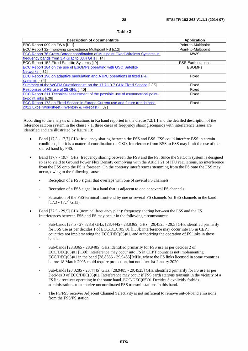
According to the analysis of allocations in Ka band reported in the clause 7.2.1.1 and the detailed description of the reference satcom system in the clause 7.1, three cases of frequency sharing scenarios with interference issues are identified and are illustrated by figure 13:
• Band [17,3 - 17,7] GHz: frequency sharing between the FSS and BSS. FSS could interfere BSS in certain conditions, but it is a matter of coordination on GSO. Interference from BSS to FSS may limit the use of the shared band by FSS.
• Band [17,7 - 19,7] GHz: frequency sharing between the FSS and the FS. Since the SatCom system is designed so as to yield to Ground Power Flux Density complying with the Article 21 of ITU regulations, no interference from the FSS onto the FS is foreseen. On the contrary interferences stemming from the FS onto the FSS may occur, owing to the following causes:
- Reception of a FSS signal that overlaps with one of several FS channels.
- Reception of a FSS signal in a band that is adjacent to one or several FS channels.
- Saturation of the FSS terminal front-end by one or several FS channels (or BSS channels in the band [17,3 - 17,7] GHz).
• Band [27,5 - 29,5] GHz (nominal frequency plan): frequency sharing between the FSS and the FS. Interferences between FSS and FS may occur in the following circumstances:
- Sub-bands [27,5 - 27,8285] GHz, [28,4445 - 28,8365] GHz, [29,4525 - 29,5] GHz identified primarily for FSS use as per decides 1 of ECC/DEC(05)01 [i.30]: interference may occur into FS in CEPT countries not implementing the ECC/DEC(05)01, and authorizing the operation of FS links in those bands.
- Sub-bands [28,8365 - 28,9485] GHz identified primarily for FSS use as per decides 2 of ECC/DEC(05)01 [i.30]: interference may occur into FS in CEPT countries not implementing ECC/DEC(05)01 in the band [28,8365 - 29,9485] MHz, where the FS links licensed in some countries before 18 March 2005 could require protection, but not after 1st January 2020.
- Sub-bands [28,8285 - 28,4445] GHz, [28,9485 - 29,4525] GHz identified primarily for FS use as per Decides 3 of ECC/DEC(05)01. Interference may occur if FSS earth stations transmit in the vicinity of a FS link receiver operating in the same band. ECC/DEC(05)01 Decides 5 explicitly forbids administrations to authorize uncoordinated FSS transmit stations in this band.
- The FS/FSS receiver Adjacent Channel Selectivity is not sufficient to remove out-of-band emissions from the FSS/FS station.

ETSI
ETSI TR 103 263 V1.1.1 (2014-07) 29
• Band [28,4465 - 28,9465] GHz (alternative frequency plan): frequency sharing between the FSS and the FS. Interferences between FSS and FS may occur, only if:
- CEPT Decision ECC/DEC/(05)01 [i.30] is not implemented in the band [28,8365 - 29,9485] MHz, where the FS links licensed in some countries before 18 March 2005 could require protection, but not after 1st January 2020.
- The FS/FSS receiver Adjacent Channel Selectivity is not sufficient to remove out-of-band emissions from the FSS/FS station.
Figure 13: Interference scenarios in Ka band
Available sharing studies are identified below:
Band [17,3 - 17,7] GHz:
In this frequency band, the main sharing issue for FSS receive terminals corresponds to uplink Earth stations used for Feeder-links of BSS systems.
ECC/DEC(05)08 [i.31] is applicable in this band and indicates however that:
• that FSS earth stations transmitting in 17,3 GHz -17,7 GHz for BSS feeder links are located at a few tens of known locations in CEPT countries.
• that the area around an FSS earth station transmitting in 17,3 GHz - 17,7 GHz for BSS feeder links where interference to an uncoordinated FSS receive earth station may be created is limited to a few tens of kilometres.
Band [17,7 - 19,7] GHz:
Sharing studies have been undertaken in CEPT SE40, and are on-going.
Band [27,5 - 29,5] GHz:
In this frequency band, FS and FSS are co-allocated at the ITU level. In CEPT, a band segmentation scheme has been implemented between FS and uncoordinated Earth stations of the FSS through the adoption of ECC/DEC(05)01, which last revision has been adopted in January 2013.
This decision defines frequency bands where uncoordinated FSS earth stations may be operated, and guard bands with the Fixed Service.
Uncoordinated FSS earth stations should not have their occupied band edges closer than 10 MHz from the edges of the bands identified for use by Terrestrial services (Fixed Service).
27.5 – 29.5 GHz
17.7 – 19.7 GHz
FSS
FS
FS
FSS
17.3 – 17.7 GHz
BSSFeeder
FSS
Communication
Possible interference

ETSI
ETSI TR 103 263 V1.1.1 (2014-07) 30
Sharing studies were conducted recently between the Fixed Service and ESOMPs. These studies can be found in ECC Report 184 [i.32]. In ITU, a proposed methodology can be found in Recommendation ITU-R SF.1719 [i.16].
7.2.1.3 Sharing and compatibility issues still to be considered
In order to assess the sharing compatibility among terrestrial and satellite systems a proper methodology has to be defined and considered, to compare different sharing techniques.
The sharing of the same frequency band between terrestrial and satellite communication will respect some protection requirements between the two systems. On one hand the incumbent (terrestrial or satellite) communications will be protected from the cognitive (satellite) communications, if active. At the same time, in order to achieve an acceptable reliability, the cognitive (satellite) link will be protected from the presence of any incumbent (terrestrial or satellite) communication. The protection requirements takes into account those defined by ITU-R and ECC.
At the same time the incumbent and cognitive systems respect some emission limits in order to avoid harmful interference towards different users. Mostly emission limits refer to in-band power limit, when the emission limit refers to the power emitted in the used frequency portion, and out of band power limit, when the emission limit refers to the power emitted outside the used frequency portion.
In order to assess the sharing compatibility some input parameters are required. The system parameters refers to those input information to be taken into account for setting up the cognitive system. The system input parameters can be grouped into three main classes: the geographical parameters, the terminal parameters and the radio interface parameters:
• Geographical parameters:
EXAMPLE 1: Coverage and Capture Areas of the incumbent and cognitive systems for a geographical point of view.
• Terminal parameters:
EXAMPLE 2: Locations/elevation/azimuth, antenna patterns, polarization of both the incumbent and the cognitive terminals.
• Radio interface parameters:
EXAMPLE 3: Link budget values, the channel rasters.
System input parameters along with protection requirements and emission limits work as an input for the CR techniques to be used for assuring an effective sharing between satellite and terrestrial components.
The different CR techniques, applied to the scenarios to be taken into account, can be compared by exploiting two main system level KPIs:
• System Capacity: The system capacity stands for the overall capacity that the system can support by taking into account both the incumbent and the cognitive systems. On one hand the cognitive techniques would allow to exploit those unused resources by the incumbent system thus increasing the overall system capacity. On the other hand the coexistence between incumbent and cognitive needs to be carefully designed for reducing the mutual interference that could result in no or low gain with respect to the system capacity. The system capacity is a good KPI because allows to compare different cognitive techniques aiming to consider that or those that allow its maximization.
• Geographical availability: The geographical availability stands for the overall area where the cognitive system can be implemented subject to the other constraints. This KPI is also function of the incumbent system density, however, given a certain density, higher is the geographical availability higher is the impact of the cognitive systems to the final users. The geographical availability allows to compare different cognitive techniques for each selected scenario with aim of selecting that technique that allow to maximize the area in which the cognitive system can be used.
The assessment of the sharing capability between incumbent and cognitive systems can be summarized by resorting to the definition of 7 cases, listed in table 4.

ETSI
ETSI TR 103 263 V1.1.1 (2014-07) 31
Table 4
Cases 1 and 2 refer to the sharing of a certain frequency band by a cognitive downlink system, where case 1 does not take into account any CR technique. The KPIs measured for the case 2 give an indication of the gain due to the exploitation of the CR techniques.
Cases 3 and 4 refer to the sharing of a certain frequency band by a cognitive uplink system, where case 3 does not take into account any CR technique. The KPIs measured for the case 4 give an indication of the gain due to the exploitation of the CR techniques.
Cases 5 and 6 refer to the sharing of a certain frequency band by a cognitive system operating in both uplink and downlink, where case 5 does not take into account any CR technique. The KPIs measured for the case 6 give an indication of the gain due to the exploitation of the CR techniques.
Case 7 acts as a theoretical reference considering the absence of any interference among incumbent and cognitive systems.
Proposed methods to compute the KPIs.
The aforementioned system-level KPI are computed through a comprehensive analysis that encompasses the service coverage of the system. Indeed the deployment of FS and BSS stations across Europe is strongly heterogeneous. This statement is mostly relevant for FS deployment, while rather few BSS stations are deployed and their footprint is limited with respect to Europe area. Furthermore, the geometry of the radio scene including interferences highly depends on the relative position of the satellite terminals with respect to satellite. Thus an analysis of the benefit brought by a CR technique on a fraction of the full coverage cannot be representative, except if a worst-case approach is considered.
In addition the computation is based on the concept of cognitive zones. For each FSS carrier, a cognitive zone is defined as the geographical area in which the carrier can only be used by employing cognitive techniques. The design of the cognitive zone will be enabled through a database dealing with the FS and BSS deployment, including geographical parameters (coverage area of the transmitting stations, and capture area of the receiving station), device parameters (location, elevation and azimuth angles, coverage footprint, height and altitude, device type) and environment parameters (frequency bands, power and polarization, number of channels).
This kind of database is typically built by national regulatory bodies. In the purpose of the computation of system-level KPI, it is likely that:
• The set of information of each database will be heterogeneous and incomplete.
• Only few countries will make available that kind of database.
Cases Interference
on DL
Interference
on UL
Cognitive radio
techniques
Scenarios
1 Yes No No A & B
2 Yes No Yes A & B
3 No Yes No C
4 No Yes Yes C
5 Yes Yes No A & B & C
6 Yes Yes Yes A & B & C
7 No No No No
interference
in the
shared band
DL CRgain
UL CRgain
DL & ULCR gain
Theoreticalreference

ETSI
ETSI TR 103 263 V1.1.1 (2014-07) 32
In case real and comprehensive data is not available, a first approach would be to utilize the network planning information of a different bandwidth range and scale the frequency carriers assuming that the propagation characteristics do not change considerably. A fallback approach would be to simulate a certain network deployment by randomly positioning the links based on a predefined spatial density. In this case, the carrier for each link should be carefully selected to ensure that no intra-system interference occurs. For the example of FS, we propose to consider that the deployment of FS is related to the population density. This strong assumption is secured through a verification performed on available database. To illustrate this point, the figure here below maps the distribution of FS stations in France in the band 17,7 GHz - 19,7 GHz. It can be seen that large concentrations of FS stations seem to fit densely populated areas.
The computation of KPI is based on the assessment of the impact of interference of FS and BSS stations, while relying on the knowledge of the deployment of FS and BSS stations. The analysis takes into account:
• the set of parameters provided by the database, which have been recalled above;
• a grid of possible locations for FSS stations, with the appropriate step;
• the system parameters of the FSS satellite system (satellite beam lay-out, satellite EIRP and G/T, terminal features, air interface, carrier bandwidth, etc.);
• the mutual interference models between FS, BSS and FSS;
• the expected QoS of each service, in order to define a protection level;
• the possible CR techniques (spectrum awareness, resource allocation, interference management) and their associated cognition level that helps in avoiding/mitigating interferences.
Figure 14: Distribution of FS stations in France
7.2.2 Transmitter parameters
7.2.2.1 FSS earth stations
This part includes the transmitter characteristics of FSS earth stations operating in the bands 29,5 GHz - 30,0 GHz and 27,5 GHz - 29,5GHz (non-exclusive bands).
7.2.2.1.1 Transmitter Output Power / Radiated Power
The compliance to EN 301 459 [i.17] is considered as baseline for the transmit parameters.

ETSI
ETSI TR 103 263 V1.1.1 (2014-07) 33
The reference transmit chain is: Modulator - HighPowerAmplifier - Antenna.
Transmission Mask (TM), (measured at modulator output): As specified in EN 302 307 [i.3] and subsequent updates.
Adjacent channel power (ACP): The adjacent channel power limitations are defined by the satellite operator and regulator and depend on the power class and type of terminal used.
Power control (PC): Power control is an option in the user terminal and if implemented it is taken into account in the requirements of the UT as outlined in EN 301 459 [i.17].
Spectral Power Density (SPD): In-band on-axis spectral power density is limited by satellite system operator constraints and regulatory requirements.
7.2.2.1.2 Antenna Characteristics
Transmission mask considered follows defined reference requirements in EN 301 459 [i.17], clause 4.2.3.
7.2.2.1.3 Operating Frequency
Preferably give several options of frequency bands and/or tuning ranges, so that CEPT/ECC-WGFM can choose the most suitable ones. Include frequency accuracy and stability and the tuning range of the equipment.
As per the frequency plan presented in clause 7.1, FSS earth stations transmit in the bands 29,5 GHz - 30,0 GHz and 27,5 GHz - 29,5 GHz (non-exclusive bands).
7.2.2.1.4 Bandwidth
Transmit bandwidth allocations depend on the achievable link budget (efficiency) as well as the required margins and the throughput to be achieved. The configurable range is:
• Minimum Tx bandwidth allocation per user terminal: 32 kHz.
• Maximum Tx bandwidth allocation per carrier and per user terminal: 2 MHz (27 MHz per Multi Frequency Time Division Multiplexing Access group of carriers).
• Maximum Tx bandwidth allocation per carrier group: 20 MHz - 30 MHz.
7.2.2.1.5 Unwanted emissions
Spurious emissions: Reference specification is EN 301 459 [i.17].
Out-of-band emissions: Defined by satellite system operator, typical 1 dBW / 4 kHz (= same reference as above).
Cross-polarization discrimination: 25 dB (min).
7.2.2.2 BSS earth stations
7.2.2.2.1 Transmitter Output Power / Radiated Power
The transmitter of the present link is the earth station for uplink to the BSS satellite.
No power limitations exist within the band, since it is not shared with other services.
A separate high power amplifier (HPA) processes the single carrier that is uplinked to one transponder. The HPA output power capability is in the range 100 W to 750 W. A typical example for the output power, at the antenna flange, is 19 dBW.
It is assumed BSS earth stations do not exceed E.I.R.P levels greater than 84 dBW as specified in table 3A2 of the Radio Regulations' appendix 30A [i.15].

ETSI
ETSI TR 103 263 V1.1.1 (2014-07) 34
7.2.2.2.2 Antenna Characteristics
The antenna gain pattern mask defined in Recommendation ITU-R S.580 [i.18] does usually apply. This mask, together with the referenced Recommendation ITU-R S.465 [i.19] and under the assumption of a large antenna diameter, is defined as follows:
���� ≤ 29 − 25 log� dBi for � ≤ 20°
≤ −3.5 dBi for 20° < � ≤ 26,3°
≤ 32 − 25 log� dBi for 26,3° < � ≤ 48°
≤ −10 dBi for 48° < � ≤ 180°
(Off-axis EIRP masks are based on a slightly different gain pattern mask, but do not exist for the frequency band considered here.)
Satellite operators might request a more stringent gain pattern mask, where the (29 - 25 log φ dBi) envelope extends to 36,3°.
Typical antennas have a diameter of 9 m and an efficiency of 60 %. This leads to an antenna gain of 62 dB at 17,7 GHz.
7.2.2.2.3 Operating Frequency
According to scenario definition, the operating frequency range is 17,3 GHz to 17,7 GHz.
BSS feeder links are operated also in the 17,7 GHz to 18,1 GHz band. This band is considered in scenario B.
7.2.2.2.4 Bandwidth
With BSS, each transponder processes a single modulated carrier. The carrier bandwidth may exceed the nominal transponder bandwidth, but should not exceed the transponder spacing. The carrier bandwidth comprises the occupied bandwidth of an ideally modulated carrier and imperfections that slightly exceed the occupied bandwidth.
Transponder bandwidth and spacing combinations are as follows.
Table 5
Transponder bandwidth Transponder spacing Remark 27 MHz 38,36 MHz Obsolete BSS
frequency plan 33 MHz 38,36 MHz In use, for example Eutelsat
Hotbird 33 MHz 39 MHz In use, for example SES Astra
Typical carrier characteristics with QPSK or 8PSK modulation (on the transponders in use) are as follows.
Table 6
Symbol rate Roll-off Ideal occupied bandwidth 27,5 Msps 35 % 37,125 MHz 29,5 Msps 25 % 36,875 MHz 30 Msps 25 % 37,5 MHz
It appears appropriate to take into account only the ideal occupied bandwidth and neglect the carrier imperfections.
7.2.2.2.5 Unwanted emissions
Unwanted EIRP emissions outside the assigned bandwidth are restricted to 4 dBW/4 kHz. This EIRP applies to the on-axis direction of the uplink antenna, whereas the EIRP towards a cognitive radio earth station is determined by the antenna gain pattern.

ETSI
ETSI TR 103 263 V1.1.1 (2014-07) 35
7.2.2.3 FS stations
FS transmitters characteristics can be found in Recommendation ITU-R F.758-5 [i.20].
7.2.2.3.1 Transmitter Output Power / Radiated Power
In addition to Recommendation ITU-R F.758-5 [i.20], information on FS power levels can be found in TR 102 243 [i.21].
7.2.2.3.2 Antenna Characteristics
Antenna characteristics can be found in Recommendations ITU-R F.699-7 [i.22] and F.1245-2 [i.38]. The choice among these two recommendations depends upon the type of sharing studies to be carried out.
7.2.2.3.3 Operating Frequency
Operating frequencies are given by channelling arrangements defined in ERC/REC 12-03 [i.23] for the band 17,7 GHz - 19,7 GHz, and in ERC Recommendation T/R 13-02 [i.33] for the band 27,5 GHz - 29,5 GHz.
7.2.2.3.4 Bandwidth
The bandwidth used by FS are according to the channelling arrangements described in ERC/REC 12-03 [i.23] for the band 17,7 GHz - 19,7 GHz, and in ERC Recommendation T/R 13-02 [i.33] for the band 27,5 GHz - 29,5 GHz.
7.2.2.3.5 Unwanted emissions
Emission masks for FS are defined in EN 302 217-2-2 [i.24], clause 4.2.4.
7.2.3 Receiver parameters
7.2.3.1 FSS earth stations
This part includes the receiver characteristics of FSS earth stations operating in the bands 17,3 GHz - 17,7 GHz and 17,7 GHz - 19,7 GHz.
Table 7: Receiver baseline parameters
Parameter Description Specification LNB gain Low Noise amplifier 55 dB to 65 dB (typical)
Typical system noise temperature
Reference system noise temperature used to evaluate the noise figure
290 K
Noise figure Noise figure over the receive band range tuned to (i.e. 500 MHz - 600 MHz)
1,5 dB maximum over tuned frequency band
Intermodulation 2nd order intermodulation measured at BUC output
26 dBc at Psat-1 dB
Blocking Maximum LNB input power aggregated allowed (above which non-linear region of LNB)
-75 dBm (typical) to -60 dBm (max)
Tuner flexibility The receiver is adjusted to a specific part of the frequency band to optimize noise figure A segmentation of the frequency band into 500 MHz band regions is proposed
500 MHz (typical) to 600 MHz (maximum)
7.2.3.2 BSS earth stations
The receiver of the present link is the input section of the BSS satellite payload.

ETSI
ETSI TR 103 263 V1.1.1 (2014-07) 36
The signals transmitted by the FSS satellite of a cognitive radio satellite system might cause interference to the receiving satellite of a BSS feeder link. Interference from the FSS satellite of the cognitive radio system is an issue of frequency coordination like interference from an FSS satellite of any conventional system. Therefore, receiver parameters of the BSS feeder link are not relevant here.
7.2.3.3 FS stations
FS receiver characteristics can be found in Recommendation ITU-R F.758-5 [i.20].
7.2.4 Channel access parameters
These parameters are system level parameters and relate to the ability of the receiver to insert into the system context of a receiver that shares the frequency access with other receivers.
It is assumed that the end user terminal of the cognitive system is capable of changing its frequency and modulation and coding parameters (physical layer channel parameters) on the forward (outbound) and on the return (inbound) link. The frequency, the modulation and coding as well as the transmit power settings can be changed as required by the system network control center (NCC) of the cognitive system.
7.2.4.1 FSS earth stations
The FSS earth station, the terminal of the cognitive system, has a reconfigurable air interface in forward and return link. The earth station is capable of accessing the frequency resources assigned by the system and to change its frequency assignments and power density parameters without losing the link to the system controlling gateway station.
The response time of the terminal to a change in its allocated capacity is defined as the "duty cycle" of the cognitive system, the time period required by the system to respond to a changing interference condition on the channel. Within the considered reference system, it takes in the order of 1 second to change down and uplink carriers.
The typical minimal frequency agility on the transmit side of the terminal is defined to be at least 20 MHz.
7.2.4.2 BSS earth stations
The channel is used by a single transmitter, which is the FSS satellite of the cognitive radio system. Therefore, channel access parameters are not relevant.
7.2.4.3 FS stations
Channel access parameters are not relevant in this case, since the FS system is incumbent and is assumed not be required to adapt to the changing environment.
7.3 Information on relevant standard(s) As per FSS earth stations as well as ESOMP (Earth Stations on Mobile Platforms), the following harmonized standards applies in Ka band allocation.
• ETSI EN 303 978 [i.25]: Satellite Earth Stations and Systems (SES); Harmonized EN for Earth Stations on Mobile Platforms (ESOMP) transmitting towards satellites in geostationary orbit in the 27,5 GHz to 30,0 GHz frequency bands; 2012-12.
• ETSI EN 301 459 [i.17]: Satellite Earth Stations and Systems (SES); Harmonized EN for Satellite Interactive Terminals (SIT) and Satellite User Terminals (SUT) transmitting towards satellites in geostationary orbit in the 29,5 GHz to 30,0 GHz frequency bands; 2007-06.
• ETSI EN 301 360 [i.26]: Satellite Earth Stations and Systems (SES); Harmonized EN for Satellite Interactive Terminals (SIT) and Satellite User Terminals (SUT) transmitting towards geostationary satellites in the 27,5 GHz to 29,5 GHz frequency bands; 2006-02.

ETSI
ETSI TR 103 263 V1.1.1 (2014-07) 37
• ETSI EN 301 359 [i.27]: Satellite Earth Stations and Systems (SES); Satellite Interactive Terminals (SIT) using satellites in geostationary orbit operating in the 11 GHz to 12 GHz (space-to-earth) and 29,5 GHz to 30,0 GHz (earth-to-space) frequency bands; 1999-04.
• ETSI EN 301 358 [i.28]: Satellite Earth Stations and Systems (SES); Satellite User Terminals (SUT) using satellites in geostationary orbit operating in the 19,7 GHz to 20,2 GHz (space-to-earth) and 29,5 GHz to 30 GHz (earth-to-space) frequency bands; 1999-04.
As per BSS earth stations, the following harmonized standards applies in Ka band allocation:
• No harmonized standard exists. BSS uplink earth stations are treated individually by administrations.
As per FS transmitters/receivers the following harmonized standards applies in Ka band allocation:
• The principles of cognitive radio techniques for SatCom operating in Ka band will also be considered during the revision of existing harmonized standards or development of new harmonized standards in ETSI TC SES in line with the results of the considerations in CEPT/ECC. The description of the precise technical details of these techniques may be subject to inclusion in harmonized standards whereas the ECC harmonization measure (ECC Decision or Recommendation) will identify the applicability of the technique in the respective frequency range.
8 Radio spectrum request and justification ECC/WGFM has already started the process of revising ERC/DEC(00)07 [i.29] and is also generating a new ECC Report, studying the enhanced operations of uncoordinated FSS Earth Stations operating in 17,7 GHz - 19,7 GHz. The present document is in support of this process. ECC/WGSE is conducting technical studies in PT SE40 in support of this work.
The principles of cognitive radio techniques for SatCom operating in Ka band as set out in clause 7.2.1 should be taken into account in the on-going investigations to find effective solutions that could improve the FS/FSS spectrum sharing.
9 Regulations
9.1 Uncoordinated FSS Earth Stations 9.1 Current regulations Include, in particular, ITU, EC and ECC applicable regulations (see also annexes B and C).
From the table of service allocations in the ITU-R radio regulation document, the main sharing scenarios are identified in table 8.
Table 8: Sharing of Ka-band according to the ITU-R radio regulation document
Frequency bands ITU-R Region 1 ITU-R Region 2 ITU-R Region 3 17,3 GHz - 17,7 GHz FSS (space-Earth)
BSS (feeder links) Radiolocation
FSS (space-Earth) BSS (feeder links)
Radiolocation
FSS (space-Earth) BSS (feeder links)
Radiolocation 17,7 GHz - 19,7 GHz FSS (space-Earth)
BSS (feeder links up 18,1 GHz) FS
FSS (space-Earth) FS
FSS (space-Earth) BSS (feeder links up 18,1 GHz)
FS 27,5 GHz - 29,5 GHz
(Note 1) FSS (Earth to space)
FS MS
FSS (Earth to space) FS MS
FSS (Earth to space) FS MS

ETSI
ETSI TR 103 263 V1.1.1 (2014-07) 38
CEPT has adopted a Decision, ECC/DEC/(05)08 [i.31], which gives guidance on the use of the band 17,3 GHz - 17,7 GHz by High Density applications in the Fixed-Satellite Service (HDFSS). The Decision stipulates that the designation of this band is without prejudice to the use of this band by BSS feeder links and that it is not allocated to any incumbent terrestrial service (except in some countries). The deployment of uncoordinated FSS Earth stations is also authorized in these bands. It is to be noted that administrations should exempt from individual licensing and allow the free circulation and use of the uncoordinated FSS earth stations operating in the band 17,3 GHz - 17,7 GHz.
CEPT has adopted a Decision, ERC/DEC(00)07 [i.29], which gives guidance on the use of the band 17,7 GHz - 19,7 GHz by Fixed Satellite Service and Fixed Services. The Decision stipulates that stations of the FSS can be deployed anywhere, but without right of protection from interference generated by Fixed Service radio stations. Nevertheless the Decision also requires both FS and FSS systems to implement interference mitigation measures. Decision ERC/DEC(00)07 [i.29] is widely implemented within CEPT, and FSS allocations are present in most CEPT countries according to the ECO Frequency Information System (EFIS).
CEPT Decision ECC/DEC/(05)01 [i.30] provides a segmentation between FS and FSS stations in the band 27,5 GHz - 29,5 GHz, which is depicted by figure 15. "Sat" and "Ter" refer to refer to FSS and FS respectively. The main points to be noted from this Decision are:
"...
• Terminals employing bands labeled "sat" do not need site coordination, and are exempted from individual license.
• In the band labeled "sat*" (28,8365-29,9485 MHz) : There are legacy FS in few countries. The FS links licensed in these countries before 18 March 2005 could require protection, but not after 1st January 2020. No new FS links can be deployed in this band.
• The out-of-band EIRP radiated by FSS terminals in FS bands below 3° elevation shall not exceed -35 dBW/MHz.
• FSS terminals shall operate above 3° elevation.
• Power Control is mandatory for FSS terminals. The maximum EIRP of FSS terminals shall not exceed a value in a range from 60dBW to 55dBW. The maximum value may be fixed nationally.
• FSS terminals shall implement a minimum guard band of 10 MHz from bands identified for FS..."
It should be noted that ECC Decisions are not mandatory instruments, and CEPT administrations may choose not to implement them.
Figure 15: Segmentation of the band 27,5 GHz - 29,5 GHz according to Decision ECC/DEC/(05)01
9.2 Proposed regulation and justification
9.2.1 FSS reception
ECC/WGFM has already started the process of revising ERC/DEC(00)07 [i.29] and is also generating a new ECC Report, studying the enhanced operations of uncoordinated FSS Earth Stations operating in 17,7 GHz - 19,7 GHz. This system reference document is prepared in support of this process. ECC/WGSE is conducting technical studies in PT SE40 in support of this work.
Uncoordinated earth stations in the frequency band 17,7 GHz - 19,7 GHz should be exempt of individual license and should be allowed for free circulation in CEPT countries.
Any sub-band not used by FS (e.g. duplex gap guard bands) within 17,7 GHz - 19,7 GHz should be identified by CEPT for protected FSS use.
27.5 27.8285 28.4445 28.8365 28.9485 29.4525 29.5Sat Ter Sat Sat* Ter Sat

ETSI
ETSI TR 103 263 V1.1.1 (2014-07) 39
Knowledge of FS characteristics (e.g. carrier bandwidth, power, Tx/Rx locations, etc.) in a data base could be exploited by the satellite cognitive radio technique to optimize the system capacity.
NOTE 1: Cognitive radio scheme may contribute to increase capacity by exploiting non exclusive FSS band along with exclusive FSS bands. However it relies on the use of exclusive band to ensure a minimum service performance for terminals under strong FS interference status.
NOTE 2: The Cognitive Radio techniques considered for Ka band will not be necessarily suitable for other frequency bands.
9.2.2 FSS transmission
Knowledge of FS characteristics (e.g. carrier bandwidth, power, Tx/Rx locations, etc.) in a data base could be exploited by the satellite cognitive radio technique to transmit in this band while avoiding interference to FS.
Provided that the efficiency of cognitive radio techniques could be demonstrated, FSS uplink use of the whole band 27,5 GHz - 29,5 GHz could be envisaged.

ETSI
ETSI TR 103 263 V1.1.1 (2014-07) 40
Annex A (informative): Bibliography RSPG11-392 Final, Radio Spectrum Policy Group (RSPG) 2011, Report on Collective Use of Spectrum (CUS) and other spectrum sharing approaches, November 2011.
NOTE: Available at http://rspg.ec.europa.eu/_documents/documents/meeting/rspg26/rspg11_392_report_CUS_other_approaches_final.pdf?bcsi_scan_A5EE077DF30AEF84=ObZZkBth7NnUv5ydA2zII7vcmi45AAAA6ewnBw==&bcsi_scan_filename=rspg11_392_report_CUS_other_approaches_final.pdf.
http://www.ict-corasat.eu/.
ETSI EG 201 788: "Electromagnetic compatibility and Radio spectrum Matters (ERM); Guidance for drafting an ETSI System Reference document (SRdoc)".

ETSI
ETSI TR 103 263 V1.1.1 (2014-07) 41
History
Document history
V1.1.1 July 2014 Publication


![TR 103 151 - V1.1.1 - Electromagnetic compatibility and ... · [i.2] ETSI TR 102 791: "Electromagnetic compatibility and Radio spectrum Matters ... AFIL Audio-Frequency Induction](https://static.fdocuments.us/doc/165x107/5ba13de809d3f2666b8bf159/tr-103-151-v111-electromagnetic-compatibility-and-i2-etsi-tr-102.jpg)