TR 103 056 - V1.1.1 - Electromagnetic compatibility and Radio
76
ETSI TR 103 056 V1.1.1 (2012-03) Electromagnetic compatibility and Radio spectrum Matters (ERM); System Reference Document; Short Range Devices (SRD); Technical characteristics for SRD equipment for social alarm and alarm applications Technical Report
Transcript of TR 103 056 - V1.1.1 - Electromagnetic compatibility and Radio

ETSI TR 103 056 V1.1.1 (2012-03)
Electromagnetic compatibility and Radio spectrum Matters (ERM);
System Reference Document; Short Range Devices (SRD);
Technical characteristics for SRD equipment for social alarm and alarm applications
Technical Report
ETSI
ETSI TR 103 056 V1.1.1 (2012-03) 2
Reference DTR/ERM-TG28-0431
Keywords alarm, radar, radio, short range, SRD, UWB
ETSI
650 Route des Lucioles F-06921 Sophia Antipolis Cedex - FRANCE
Tel.: +33 4 92 94 42 00 Fax: +33 4 93 65 47 16
Siret N° 348 623 562 00017 - NAF 742 C
Association à but non lucratif enregistrée à la Sous-Préfecture de Grasse (06) N° 7803/88
Important notice
Individual copies of the present document can be downloaded from: http://www.etsi.org
The present document may be made available in more than one electronic version or in print. In any case of existing or perceived difference in contents between such versions, the reference version is the Portable Document Format (PDF).
In case of dispute, the reference shall be the printing on ETSI printers of the PDF version kept on a specific network drive within ETSI Secretariat.
Users of the present document should be aware that the document may be subject to revision or change of status. Information on the current status of this and other ETSI documents is available at
http://portal.etsi.org/tb/status/status.asp
If you find errors in the present document, please send your comment to one of the following services: http://portal.etsi.org/chaircor/ETSI_support.asp
Copyright Notification
No part may be reproduced except as authorized by written permission. The copyright and the foregoing restriction extend to reproduction in all media.
© European Telecommunications Standards Institute 2012.
All rights reserved.
DECTTM, PLUGTESTSTM, UMTSTM and the ETSI logo are Trade Marks of ETSI registered for the benefit of its Members. 3GPPTM and LTE™ are Trade Marks of ETSI registered for the benefit of its Members and
of the 3GPP Organizational Partners. GSM® and the GSM logo are Trade Marks registered and owned by the GSM Association.
ETSI
ETSI TR 103 056 V1.1.1 (2012-03) 3
Contents
Intellectual Property Rights ................................................................................................................................ 6
Foreword ............................................................................................................................................................. 6
Introduction ........................................................................................................................................................ 6
1 Scope ........................................................................................................................................................ 7
2 References ................................................................................................................................................ 7
2.1 Normative references ......................................................................................................................................... 7
2.2 Informative references ........................................................................................................................................ 8
3 Definitions and abbreviations ................................................................................................................. 11
3.1 Definitions ........................................................................................................................................................ 11
3.2 Abbreviations ................................................................................................................................................... 12
4 Comments on the System Reference Document .................................................................................... 12
4.1 Statements by ETSI members .......................................................................................................................... 12
5 Presentation of alarm and social alarm devices, systems and applications ............................................ 13
5.1 Overview: type of application .......................................................................................................................... 14
5.2 Background information ................................................................................................................................... 14
5.2.1 Fire and smoke ............................................................................................................................................ 14
5.2.2 Building intrusion detection and building security ..................................................................................... 17
5.2.3 Social alarm ................................................................................................................................................ 19
5.3 Application details "Alarm and Social Alarm applications" ............................................................................ 21
5.3.1 Type 1: fire and smoke ............................................................................................................................... 21
5.3.2 Type 2: building intrusion/security ............................................................................................................. 24
5.3.2.2 Asset tracking ........................................................................................................................................ 25
5.3.2.3 Surveillance applications ...................................................................................................................... 26
5.3.2.3.1 Video application for surveillance ................................................................................................... 26
5.3.2.4 Microwave sensor for surveillance ....................................................................................................... 26
5.3.3 Type 3: social alarm applications ............................................................................................................... 26
5.3.3.1 Private social alarm/telecare.................................................................................................................. 27
5.3.4 Type 4: technical alarms/building surveillance and maintenance ............................................................... 28
5.3.5 Type 5: Integrated systems ......................................................................................................................... 28
5.3.5.1 Professional system for healthcare and emergency services ................................................................. 28
5.3.5.2 Assisted living/Ambient Assisted Living (AAL) .................................................................................. 28
5.3.6 M2M service layer ...................................................................................................................................... 30
6 Market information................................................................................................................................. 30
6.1 New additional applications for alarm systems ................................................................................................ 31
6.1.1 Image transmission ..................................................................................................................................... 31
7 Technical information ............................................................................................................................ 32
7.1 Changes in the environment: Transmitters in adjacent bands .......................................................................... 32
7.2 Requirements/applications standardisation ...................................................................................................... 32
7.2.1 Data Traffic ................................................................................................................................................. 32
7.2.2 Reliability ................................................................................................................................................... 33
7.2.3 Latency ....................................................................................................................................................... 33
7.2.4 Safety Related Applications in the SRD Bands .......................................................................................... 33
7.2.5 Image transmission ..................................................................................................................................... 34
8 Radio spectrum request and justification ............................................................................................... 34
8.1 Current regulations ........................................................................................................................................... 34
8.2 Application Specific Alarm Sub-bands ............................................................................................................ 35
8.3 Spectrum Efficiency and Occupancy ............................................................................................................... 36
8.4 New possible regulations .................................................................................................................................. 36
8.4.1 Proposal for dedicated frequency ranges for alarm and social alarms/applications .................................... 37
8.4.2 Shared frequency ranges with other SRDs ................................................................................................. 38
8.4.3 New requirements for existing allocation ................................................................................................... 38

ETSI
ETSI TR 103 056 V1.1.1 (2012-03) 4
8.4.4 Other frequency ranges / technologies ........................................................................................................ 38
8.4.4.1 L-Band (1,4 GHz) ................................................................................................................................. 38
8.4.4.2 UWB below 10,6 GHz .......................................................................................................................... 39
9 Main conclusions .................................................................................................................................... 39
10 Requested ECC and EC actions ............................................................................................................. 39
11 Expected ETSI actions ........................................................................................................................... 40
Annex A: Detailed application information ......................................................................................... 41
A.1 Overview of types for social alarm and alarm applications ................................................................... 41
A.2 Type 1 fire and smoke ............................................................................................................................ 41
A.2.1 Background information and motivation. ......................................................................................................... 41
A.2.2 Detailed application description ....................................................................................................................... 42
A.2.3 Typical usage time and traffic evaluation of such device ................................................................................. 43
A.2.3.1 Size of Alarm systems ................................................................................................................................ 43
A.2.3.2 specific DC requirement for huge systems / networks ................................................................................ 43
A.3 Type 2: building intrusion and security .................................................................................................. 43
A.3.1 Background and justification ............................................................................................................................ 43
A.3.2 Detailed application description ....................................................................................................................... 44
A.3.3 Typical usage time and travel evaluation of such device ................................................................................. 45
A.4 Image transmission ................................................................................................................................. 45
A.4.1 Background and justification ............................................................................................................................ 45
A.4.2 Detailed application description ....................................................................................................................... 46
A.4.3 Typical usage time and traffic evaluation of such device ................................................................................. 46
A.5 Type 3: social alarm applications ........................................................................................................... 47
A.5.1 Background and justification ............................................................................................................................ 47
A.5.2 Detailed application description ....................................................................................................................... 47
A.5.2.1 Private social alarm / telecare application ................................................................................................... 47
A.5.3 Typical usage time and traffic evaluation of such device ................................................................................. 48
A.6 Type 4: technical alarms / building surveillance .................................................................................... 48
A.6.1 Background and justification ............................................................................................................................ 48
A.6.2 Detailed application description ....................................................................................................................... 48
A.7 Type 5 integrated systems ...................................................................................................................... 49
A.7.1 Ambient Assisted Living .................................................................................................................................. 49
A.7.1.1 Background and justification ...................................................................................................................... 49
A.7.1.2 Detailed application description ................................................................................................................. 51
A.7.2 Personal location information / example "Nurse call" ...................................................................................... 53
Annex B: Detailed market information ............................................................................................... 57
B.1 Type 1 fire and smoke ............................................................................................................................ 57
B.2 Type 2: intrusion and security ................................................................................................................ 57
B.2.1 Image transmission ........................................................................................................................................... 58
B.3 Type 3: social alarm application ............................................................................................................ 59
Annex C: Additional technical information ......................................................................................... 60
C.1 Technical description ............................................................................................................................. 60
C.1.1 Systems overview and installation requirements .............................................................................................. 60
C.1.1.1 Battery lifetime ........................................................................................................................................... 60
C.1.1.2 Frequency usage ......................................................................................................................................... 60
C.2 Technical justifications for spectrum ..................................................................................................... 60
C.2.1 Typical parameters ........................................................................................................................................... 60
C.2.1.1 Type 1 ......................................................................................................................................................... 61
C.2.1.2 Type 2 ......................................................................................................................................................... 62
C.2.1.2.1 Image transmission................................................................................................................................ 62

ETSI
ETSI TR 103 056 V1.1.1 (2012-03) 5
C.3 Collision probability ............................................................................................................................... 63
Annex D: Compatibility issues .............................................................................................................. 65
D.1 The Threat from LTE ............................................................................................................................. 65
D.1.1 LTE Technology .............................................................................................................................................. 65
D.1.2 Separation Distance from Alarm Systems ........................................................................................................ 66
D.1.3 Improved signalling for Alarm systems ........................................................................................................... 66
D.2 Existing Regulation ................................................................................................................................ 67
Annex E: 169 MHz for social alarm ..................................................................................................... 70
Annex F: Bibliography .......................................................................................................................... 72
History .............................................................................................................................................................. 76

ETSI
ETSI TR 103 056 V1.1.1 (2012-03) 6
Intellectual Property Rights IPRs essential or potentially essential to the present document may have been declared to ETSI. The information pertaining to these essential IPRs, if any, is publicly available for ETSI members and non-members, and can be found in ETSI SR 000 314: "Intellectual Property Rights (IPRs); Essential, or potentially Essential, IPRs notified to ETSI in respect of ETSI standards", which is available from the ETSI Secretariat. Latest updates are available on the ETSI Web server (http://ipr.etsi.org).
Pursuant to the ETSI IPR Policy, no investigation, including IPR searches, has been carried out by ETSI. No guarantee can be given as to the existence of other IPRs not referenced in ETSI SR 000 314 (or the updates on the ETSI Web server) which are, or may be, or may become, essential to the present document.
Foreword This Technical Report (TR) has been produced by ETSI Technical Committee Electromagnetic compatibility and Radio spectrum Matters (ERM).
The present document includes necessary information to support the co-operation under the MoU between ETSI and the Electronic Communications Committee (ECC) of the European Conference of Postal and Telecommunications Administrations (CEPT).
Introduction The present document has been developed to support the co-operation between ETSI and the Electronic Communications Committee (ECC) of the European Conference of Postal and Telecommunications Administrations (CEPT).
The present document is intended to help finding appropriate ways to ensure that:
1) established wireless alarm and social alarm systems can be operated and used future-proofed;
2) evolving new applications (e.g. ambient assisted living, improved medical monitoring and image transmission) for wireless alarm and social alarm systems can be used under the regulatory framework.

ETSI
ETSI TR 103 056 V1.1.1 (2012-03) 7
1 Scope The present document describes requirements for alarm and social alarm devices, systems and applications.
It is a common feature of all alarms that an alarm message, is passed to a place (e.g. operation centre), where experienced decision takers induce necessary actions, to prevent possible harm to life and limb, as well as start counter actions to stop a process indicated as highly critical or instable.
Due to the potential impacts of false or delayed alarm messages a minimum set of requirements for an alarm system has to be taken into account during the planning / installation phase. A high number of false alarms could lead to a desensitization of the users (e.g. fire / intrusion) or the "helpers" (e.g. emergency service in a social alarm system), which might result in ignored alarms, where every delay of an alarm message would result in an increased risk situation.
The following minimum set of requirements should be taken into account:
• Reliable work 24 h a day over the whole year.
• Avoidenance of blocking / interference by other wireless systems.
• Fast transmission times of an alarm message including minimised delay from the trigger.
• Redundant signal and transmission paths (e.g. multi path networks).
• Non-susceptible to changes in the signal paths (e.g. changes of arrangements/constructions inside a building) to guarantee functionality and reachability in the operating area of the alarm system.
• Easy to use manual triggering (e.g. social alarm push button).
• Automatic transmission of the alarm message to the "final receiver" (e.g. fire operation centre), after triggering.
• Fall back / escalation steps to react on a first blocking of a signal or receiption of updated information (e.g. enlarged area of fire).
The present document includes the necessary information to support the co-operation between ETSI and the ECC of the CEPT including:
• Detailed market information (annex A).
• Technical information (annex B).
• Expected compatibility issues (annex C).
2 References References are either specific (identified by date of publication and/or edition number or version number) or non-specific. For specific references, only the cited version applies. For non-specific references, the latest version of the reference document (including any amendments) applies.
Referenced documents which are not found to be publicly available in the expected location might be found at http://docbox.etsi.org/Reference.
NOTE: While any hyperlinks included in this clause were valid at the time of publication, ETSI cannot guarantee their long term validity.
2.1 Normative references The following referenced documents are necessary for the application of the present document.
Not applicable.

ETSI
ETSI TR 103 056 V1.1.1 (2012-03) 8
2.2 Informative references The following referenced documents are not necessary for the application of the present document but they assist the user with regard to a particular subject area.
[i.1] ERC/REC 70-03: "Relating to the use of short range devices (SRD)".
NOTE: Available at: http://www.erodocdb.dk/doks/implement_doc_adm.aspx?docid=1622.
[i.2] ETSI EN 300 220 (all parts) (V2.3.1): "Electromagnetic compatibility and Radio spectrum Matters (ERM); Short Range Devices (SRD); Radio equipment to be used in the 25 MHz to 1 000 MHz frequency range with power levels ranging up to 500 mW".
[i.3] CEN EN 14604:2005: "Smoke alarm devices".
[i.4] CEPT ECC Report 37: "Compatibility of planned SRD applications with currently existing radio communication applications in the frequency band 863 - 870 MHZ", Granada, February 2004.
[i.5] EN 54 (all parts): "Fire detection and fire alarm systems", details see annex E.
NOTE: Extra part 25:2008: "Fire detection and fire alarm systems - Part 25: Components using radio links and system requirements".
[i.6] European Commission Decision 2008/432/EC of 23 May 2008 (amending Decision 2006/771/EC) on harmonization of the radio spectrum for use by short-range devices.
[i.7] European Commission Decision 2009/381/EC of 13 May 2009 amending Decision 2006/771/EC on harmonisation of the radio spectrum for use by short-range devices (notified under document number C(2009) 3710).
[i.8] ETSI EN 302 065 (all parts) (V1.1.1): "Electromagnetic compatibility and Radio spectrum Matters (ERM); Short Range Devices (SRD) using Ultra Wide Band technology (UWB) for communications purposes; Harmonized EN covering the essential requirements of article 3.2 of the R&TTE Directive".
[i.9] Directive 1999/5/EC of the European Parliament and of the Council of 9 March 1999 on radio equipment and telecommunications terminal equipment and the mutual recognition of their conformity (R&TTE Directive).
[i.10] ETSI EN 300 440 (all parts) (V1.2.1): "Electromagnetic compatibility and Radio spectrum Matters (ERM); Short range devices; Radio equipment to be used in the 1 GHz to 40 GHz frequency range.
[i.11] ETSI EN 302 500 (all parts) (V2.1.1): "Electromagnetic compatibility and Radio spectrum Matters (ERM); Short Range Devices (SRD) using Ultra WideBand (UWB) technology; Location Tracking equipment operating in the frequency range from 6 GHz to 9 GHz".
[i.12] ETSI EN 300 330 (Part 1 V1.7.1; Part 2 V1.5.1.): "Electromagnetic compatibility and Radio spectrum Matters (ERM); Short range Devices (SRD); Radio equipment in the frequency range 9 kHz to 25 MHz and inductive loop systems in the frequency range 9 kHz to 30 MHz".
NOTE: Decision will be amended during ETSI publication process for the present document.
[i.13] CEPT ECC/DEC (06)12 of 1 December 2006, amended 31st October 2008 on supplementary regulatory provisions to Decision ECC/DEC/ (06)04 for UWB devices using mitigation techniques.
NOTE: Decision will be included into [i.16] during the ETSI publication process of the present document.
[i.14] VdS Guidelines for Smoke Alarm Devices (VdS 3515en) "Smoke Alarm Devices using Radio Links; Requirements and Test Methods".
[i.15] CEN EN 50131: "Alarm systems - Intrusion alarm systems (all parts)", details see annex F Bibliography.

ETSI
ETSI TR 103 056 V1.1.1 (2012-03) 9
[i.16] CEN EN 50134: "Alarm systems - Social alarm systems (all parts)".
NOTE: See details in annex F Bibliography.
[i.17] ETSI EN 300 328 (V1.7.1): "Electromagnetic compatibility and Radio spectrum Matters (ERM); Wideband transmission systems; Data transmission equipment operating in the 2,4 GHz ISM band and using wide band modulation techniques; Harmonized EN covering essential requirements under article 3.2 of the R&TTE Directive".
[i.18] ETSI EN 300 113-1 (V 1.4.1): "Electromagnetic compatibility and Radio spectrum Matters (ERM); Land mobile service; Radio equipment intended for the transmission of data (and/or speech) using constant or non-constant envelope modulation and having an antenna connector; Part 1: Technical characteristics and methods of measurement".
NOTE: Link from EN 54-25 "Spurious response rejection".
[i.19] Report: "ICT enabled independent living for elderly, A status-quo analysis on products and the research landscape in the field of Ambient Assisted Living (AAL) in EU-27", ISBN 978-3-89750-160-7.
[i.20] European Commission, Special Report No 1: "The impact of ageing on public expenditure: projections for the EU25 Member States on pensions, healthcare, long-term care, education and unemployment transfers (2004 -50)". Report prepared by the Economic Policy Committee and the European Commission (DG ECFIN). Page 30.
NOTE: Data on Bulgaria and Romania has been added on the basis of current numbers to be found on the website of Eurostat, see http://ec.europa.eu/eurostat.
[i.21] "European Smart Homes and Assisted Living - Advanced Technologies and Global Market" (2009-2014) by: marketsandmarkets.com Publishing Date: November 2009 Report Code: SE 1206.
[i.22] Frank Wartena, Johan Muskens and Lars Schmitt, Philips Research Europe, Eindhoven, The Netherlands.
NOTE: See The Continua Health Alliance - The Impact of a Personal Telehealth Ecosystem.
[i.23] IEEE Pervasive Computing, Copyright (c) 2007 IEEE. Reprinted from (Pervasive Computing).
NOTE: See Continua: An Interoperable Personal Healthcare Ecosystem.
[i.24] EC Mandate M-403: "eHealth Interoperability, Mandate to the European Standardisation Organisations CEN, CENELEC and ETSI in the field of Information and Communication Technologies, applied to the domain of eHealth".
[i.25] EC Mandate M441: "Smart Metering Mandate".
[i.26] EC Mandate M490: "Smart Grid Mandate".
[i.27] ETSI M2M / smart metering discussion in TC M2M, join CEN / CENELEC / ETSI standardization activities and ERM TG28 (e.g. ETSI TR 102 886 and TS 102 887).
[i.28] ETSI TR 102 649-2 "Electromagnetic compatibility and Radio spectrum Matters (ERM); Technical characteristics of Short Range Devices (SRD) and RFID in the UHF Band; System Reference Document for Radio Frequency Identification (RFID) and SRD equipment; Part 2: Additional spectrum requirements for UHF RFID, non-specific SRDs and specific SRDs".
[i.29] ECC FM22 measurement campaign, report will prepared till end of 2011.
NOTE: See WG FM Workshop on Future UHF Spectrum use for SRD, RFID and Smart Metering 04-05 April 2011 – Mainz (Germany), Spectrum Monitoring Campaign 863 – 870 MHz, Session A, see ECO webpage, www.ero.dk.
[i.30] ETSI TR 102 732: "Machine to Machine Communications (M2M); Use cases of M2M applications for eHealth".

ETSI
ETSI TR 103 056 V1.1.1 (2012-03) 10
[i.31] Commission Recommendation 2011/413/EU of 11 July 2011 on the research joint programming initiative 'More years, better lives - the potential and challenges of demographic change'.
[i.32] CEN EN 14604:2009-02: "Smoke alarm devices".
[i.33] RSCOM guidance to CEPT on 5th update of EC Decision.
NOTE: Available at http://www.cept.org/Documents/srd/mg/706/SRDMG_11_069_Guidance _Letter_5th_Update_EC_DEC_SRD or see ECC docbox folder for ECC FM PT SRD-MG: Document number SRDMG (11)069.
[i.34] CTIF report; No13, 2008: "Center of Fire Statistics".
NOTE: See www.ctif.org.
[i.35] VdS-3438: "2010-02 VdS-Richtlinien für Home-Gefahren-Managementsysteme - Anforderungen an Anlageteile".
[i.36] VdS 2227: "Richtlinien für Einbruchanlagen, Allgemeine Anforderungen und Prüfmethoden und VdS2227en, Intruder Alarm Systems, General Requirements and Test methods".
[i.37] Data on "Crime and criminal justice" in the EU.
NOTE: http://epp.eurostat.ec.europa.eu/portal/page/portal/crime/data/database
[i.38] CEPT reports for the digital dividend range (790 - 862 MHz) (CEPT report 029, CEPT report 030, CEPT report 031 and CEPT report 032).
[i.39] Population projections 2008-2060 .
NOTE: http://europa.eu/rapid/pressReleasesAction.do?reference=STAT/08/119&format= HTML&aged=0&language=EN&guiLanguage=en
[i.40] Eurostat Database.
NOTE: Available at http://epp.eurostat.ec.europa.eu/portal/page/portal/population/data/database.
[i.41] Report B833-19: "European Social Alarms Markets".
NOTE: See www.frost.com.
[i.42] Council Directive 89/106/EEC of 21 December 1988 on the approximation of laws, regulations and administrative provisions of the Member States relating to construction products.
[i.43] ITU-R Recommendation SM.1046-2: "Definition of spectrum use and efficiency of a radio system".
[i.44] Commission Decision 2005/928/EC of 20 December 2005 on the harmonisation of the 169,4-169,8125 MHz frequency band in the Community.
[i.45] ETSI TS 102 887: "Electromagnetic compatibility and Radio spectrum Matters (ERM); Short Range Devices; Smart Metering Wireless Access Protocol".
[i.46] IEEE 802.15.4g: "Smart Utility Networks (SUN) Overview".
[i.47] Directive 2002/91/EC of the European Parliament and of the Council of 16 December 2002 on the energy performance of buildings.
[i.48] Directive 2006/32/EC of the European Parliament and of the Council of 5 April 2006 on energy end-use efficiency and energy services and repealing Council Directive 93/76/EEC.
[i.49] ETSI EN 301 908-13: "IMT cellular networks; Harmonized EN covering the essential requirements of article 3.2 of the R&TTE Directive; Part 13: Evolved Universal Terrestrial Radio Access (E-UTRA) User Equipment (UE)".

ETSI
ETSI TR 103 056 V1.1.1 (2012-03) 11
[i.50] Approved Document B (Fire safety) Volume 2: "Buildings other than dwellinghouses" (2006 Edition).
NOTE: Source Planning portal: http://www.planningportal.gov.uk.
[i.51] GDV - Gesamtverband der Deutschen Versicherungswirtschaft e.V, statistical report 2007.
[i.52] ERC Decision ERC/DEC/(01)09 of 12 March 2001on harmonised frequencies, technical characteristics and exemption from individual licensing of Short Range Devices used for Alarms operating in the frequency bands 868.60 - 868.7 MHz 869.25 - 869.3 MHz, 869.65 - 869.7 MHz.
[i.53] ECC Decision ECC/DEC/(05)05 of 18 March 2005 on harmonised utilisation of spectrum for IMT-2000/UMTS systems operating within the band 2500 – 2690 MHz () (2008/477/EC).
[i.54] ERC Decision ERC/DEC/(97)06 of 30 June 1997 on the harmonised frequency band to be designated for Social Alarm Systems.
[i.55] Ofcom Consultation and information on technical licence conditions for 800 MHz and 2.6 GHz spectrum and related matters.
[i.56] ECC PT SE24: "Draft Report on Improving Spectrum Efficiency, a work in progress in WI23".
[i.57] ERC Decision ERC/DEC/(01)04 of 12 March 2001 on harmonised frequencies, technical characteristics and exemption from individual licensing of Non-specific Short Range Devices operating in the frequency bands 868.0 - 868.6 MHz, 868.7 - 869.2 MHz, 869.4 - 869.65 MHz, 869.7 - 870.0 MHz.
3 Definitions and abbreviations
3.1 Definitions For the purposes of the present document, the following terms and definitions apply:
alarm: use of radio communication for indicating an alert condition at a distant location
alarm time: duration between alarm trigger and arrival of "help"
alarm transmission time: duration between alarm trigger and outgoing alarm signal
assisted living residences: or assisted living facilities (ALFs) provide supervision or assistance with activities of daily living (ADLs); coordination of services by outside health care providers; and monitoring of resident activities to help to ensure their health, safety, and well-being.
assisted living: supported living in the private environment
social alarm: alarm to assist elderly or disabled people when they are in distress
social alarm devices: devices that allow reliable communication for a person in distress in a limited area to initiate a call for assistance by a simple manipulation
telecare: remote care of old and physically less able people which is offering the care and reassurance needed to allow them to remain living in their own homes
NOTE: The use of sensors may be part of a package which can provide support for people with illnesses such as dementia, or people at risk of falling.

ETSI
ETSI TR 103 056 V1.1.1 (2012-03) 12
3.2 Abbreviations For the purposes of the present document, the following abbreviations apply:
AAL Ambient Assisted Living CEPT European Conference of Postal and Telecommunications Administrations CEN European Committee for Standardization CTIF Comité Technique International de prévention et d'extinction du Feu ECC Electronic Communications Committee EC European Commission, the administration of the European Union ERO European Radio communications Office e.r.p. effective radiated power ETSI European Telecommunications Standards Institute EU European Union LTE new mobile communication system, "long term evolution" NIST National Institute of Standards and Technology, United States RSCOM Radio Spectrum Committee UK United Kingdom VdS Vertrauen durch Sicherheit
4 Comments on the System Reference Document
4.1 Statements by ETSI members Silver Spring Network comment:
The authors of this comment do not believe that the present document presents adequate reasons for additional spectrum to be designated for exclusive alarm use.
In the expansion spectrum to be shared with the GSM-R primary users (873 MHz to 876 MHz), the work done so far is based on sharing spectrum using specific system design techniques to protect the GSM-R device operation. It is noted that clause 8.4.1, Table 8.1 includes:
Note 3: Indicative DC:
- Max Transmitter On Time / per single transmission: [700 ms] - Min Transmitter Off Time between two transmissions: [400 ms] - Sum of Ton times / minute = DC/min [2,5]%/min - Sum of Ton times / hour = DC/hr: [0,1]%/hr
These indicative values are inconsistent with the requirements specified in TR 102 886 [i.27] which develops a sharing strategy based on the behaviour of the GSM-R channel codec and its inherent recovery time.
With respect to the discussion on safety of life in clause 7.2.4 Safety Related Applications it is important to recall the following note from the foreword of ERC/REC 70-03 [i.1]:
When selecting parameters for new SRDs, which may have inherent safety of human life implications, manufacturers and users should pay particular attention to the potential for interference from other systems operating in the same or adjacent bands. Manufacturers should advise users on the risks of potential interference and its consequences.
It is clear that SRDs have no protection against interference from other spectrum users and consequently no guarantees of service can be provided. Therefore all SRD systems should be designed from a spectrum sharing perspective.
With respect to clause 8.2, it is argued that:
The recommended exclusivity of the alarm sub-bands has, however, been compromised. The UK and Netherlands (and possibly others in the future) have been more permissive than the EC Decision and permitted non specific use (band g in Rec 70-03 Annex 1) across the whole of 863 MHz to 870 MHz, including the alarm sub-bands.
Based on this more liberal use of SRD spectrum by low duty cycle SRDs (permitted under EU Decision 2006/art.3 paragraph 3 and Technical annex), the SRDoc argues for the identification of an additional 400 kHz of exclusive use spectrum from 875,6 MHz to 876 MHz.

ETSI
ETSI TR 103 056 V1.1.1 (2012-03) 13
However, as further identified in clause 8.2, the SRDoc recognizes that such a strategy for exclusive use sub-division of the SRD spectrum is "swimming against the regulatory tide". The permitted relaxing of regulations to allow additional applications to use the scarce spectrum resource by European regulators is not a sufficient argument for demanding further exclusive use spectrum even taking into account the expected increase in alarm market size.
The authors of this comment believe that better engineering applied to the use of the existing specific alarm SRD spectrum (e.g. 868,6 MHz to 868,7 MHz; 869,2 MHz to 869,4 MHz and 869,65 MHz to 869,70 MHz) for necessary purposes only (e.g. true alarm functions) combined with use of shared SRD spectrum for other functions (e.g. device management) would provide significant improvements in alarm spectrum use and obviate the need for identification of further dedicated-use spectrum.
The authors also believe advances in engineering practice and component design can, and will continue to do so in the future, reduce the relevance of antenna and filter performance for not employing the available dedicated alarm spectrum resources at 169 MHz.
In conclusion, this comment does not support the demand for an exclusive use band to be defined for alarms in the 873 MHz to 876 MHz spectrum and argues that a strategy for sharing existing and new SRD spectrum, together with good engineering practice and use of existing alarm SRD allocations, can satisfy the additional requirements identified both in the present document and SRDoc TR 102 649-2 [i.28].
5 Presentation of alarm and social alarm devices, systems and applications
The present document gives an overview of and describes requirements for alarm and social alarm devices, systems and applications.
In a report issued by Eurostat, the Statistical Office of the European Communities [i.39] it is projected that the EU27 population to continue to grow older, with the share of the population aged 65 years and over rising from 17,1 % in 2008 to 30,0 % in 2060, and those aged 80 and over rising from 4,4 % to 12,1 % over the same period [i.40].
This analysis, as well as the "Commission Recommendation of 11 July 2011 on the research joint programming initiative 'More years, better lives - the potential and challenges of demographic change' (2011/413/EU)", [i.31] lead to the conclusion that the potential needs for alarm systems including social alarms will grow significantly and will represent an increasing part of Short Range Devices in the coming years and for a long time.
To cope with this predicted situations and the increasing needs and requirements for alarms and social alarms a stable regulatory framework is necessary.

ETSI
ETSI TR 103 056 V1.1.1 (2012-03) 14
5.1 Overview: type of application
Figure 5.1: Overview alarm and social alarm applications
5.2 Background information
5.2.1 Fire and smoke
For detailed information, about the incident (e.g. number of fires, people killed in a fire) see: http://www.ctif.org/ (Homepage of International association of fire and rescue service).
Table 5.1: Number of fires in France, United Kingdom, Italy, Russia and Germany in the year 2002 to 2006
year France UK Italy Russia Germany 2002 323 241,00 519 373,00 180 327,00 260 800,00 183 913,00 2003 394 707,00 621 000,00 218 486,00 239 289,00 213 035,00 2004 334 421,00 443 000,00 212 837,00 233 200,00 179 272,00 2005 376 600,00 430 291,00 218 858,00 229 800,00 158 600,00 2006 359 300,00 436 047,00 227 014,00 220 400,00 187 604,00

ETSI
ETSI TR 103 056 V1.1.1 (2012-03) 15
Following information taken out of CTIF report No. 13 from 2008 [i.34]:
Figure 5.2: Average number of people died during a fire / per 100 000 in (not for all countries detailed information's available)
The total alarm time and the alarm transmission with a high reliability are very important. The following key points are taken as arguments to install smoke / fire alarm systems:
1) To reduce the amount of loss (material).
2) To reduce the number of people killed by a fire.
For both points a very short alarm time is necessary (see Figure 5.3). The reason for that is that a fire has different levels: first the "Beginning" in which it is relatively easyto extinguish (time windows < 4 min), then level two "Burning", the effort to fight the fire is much higher and inside a building a lot of smoke will be generated, which is very dangerous for the people. (time window worst case < 8 min). And then we reach the last and very critical level, "Burn over" � the smoke inside the building will burn (based on the enormous heat) � the whole room is destroyed. (after 8 min).
If we now compare the fire levels with the reaction / time of the fire-fighter at the scene of fire (e.g. in Germany it is required that professional fire brigade has to reach in 12 min, the voluntary fire brigade in 12 to 20 min), then it is clear that to achieve this a rapid and reliable alarm is necessary.

ETSI
ETSI TR 103 056 V1.1.1 (2012-03) 16
Figure 5.3: Increase of the amount of loss during a fire against the reaction time and necessary effort of fire fighters
Most victims in such fires die due to smoke poisoning. It is therefore essential that, in the event of a fire, all people in a building are warned within the first few minutes in order to evacuate the building within the time the fire brigade needs to get to the place of the fire. Smoke alarm devices are the best possible way to warn people in a very early stage of the fire. In countries like USA, UK and Sweden, where these devices have had to be installed by law for many years, the numbers of victims has been reduced by up to 50 % since the introduction of these regulations.
During recent years the following countries introduced laws to force house owners to install smoke alarm devices in dwellings:
• Norway since 1990
• UK since 1992
• Finland since 2002
• Germany since 2003
• Denmark since 2004
• Sweden since 2004
• Austria since 2007
• Ireland since 1992
• Netherlands since 2002
• Belgium since 2009
• France since 2009 (new houses)
• France from 2015 (all houses)
Regulation differs from country to country (some more detailed examples):

ETSI
ETSI TR 103 056 V1.1.1 (2012-03) 17
In Great Britain the obligation exists since 1992 for the installation of smoke detectors in new buildings, also in private households (Building Regulations Doc. B [i.50] in 1992), because there experience most fire dead persons and fire-hurt (fire-violated) are to be deplored. Besides, obligation is at least one smoke detector floor. Since introduction of the equipment obligation the number of the fire dead persons has sunk (dropped) up to 40 %. The equipment degree amounts at present to approximately 90 % (1987: 9 %, in 1994: 75 %).
In Ireland similar regulations are considered like in England, but here the responsible social ministry has in the years 1996 - summer, 1998 given a smoke detector to every pensioner.
Since 1990 Norway has regulated that in every household a smoke detector and fire-fighting equipment, at least a fire extinguisher is required. Legally the installation at least of one smoke detector per floor is prescribed. Today 98 % of the households are equipped.
In Sweden 70 % of the houses are equipped with smoke detectors. Here one speaks of a decrease of the fire victim numbers about 50 %.
In the Netherlands the equipment degree with smoke detectors lay up to the year 2000 only between 3 % and 10 %. Since 01/07/2002 there is a decision that in new buildings (ready for occupation) an installation, at least of one smoke detector, with a connection to the normal 230-V electricity supply and with integrated emergency current-battery. This sensor has to be installed in the escape routes. As in France smoke alarm devices based in ionization sensor technology are forbidden.
In 2005, 60 % of the houses (voluntarily or legally obliged) had one or several smoke detectors.
In 2006, there were already 64 % and in 2007: 68 %.
A poll in 2007 yielded:
• 57 % of respondents occasionally clean the smoke detector
• 73 % have changed already once the battery
• 87 % have already checked the smoke detector
In Germany the smoke detector obligation is a federal state topic and is anchored in the regional building codes. So far there is a smoke detector obligation in 9 federal states, for the most part for new buildings and supply buildings. On account of the extensive public relations the results of the Fors a study of 2006 already show an equipment the private budget of 31 % (1999: 5 % to 7 %). Experts are sure that a significant rise cannot be reached without legislation, however, any more.
An evaluation of the results of the smoke detector obligation will be possible in the separate federal states only some time after entry of the implementation terms.
Sources:
• Nederland's Brandwonden Stichting
• Summary fire and rescue service statistics, UK, 2006
• CTIF (Comité Technique International de prévention et d'extinction du Feu)
• www.rauchmelder-lebensretter.de
5.2.2 Building intrusion detection and building security
Details for intrusion systems (e.g. application test requirements) can be found in [i.35] and [i.36].
In the past years the number of crimes (domestic burglary / dwelling), see Table 5.3 and the damages by building insurance has been going down (source http://epp.eurostat.ec.europa.eu/portal/page/portal/crime/data/database [i.37]).
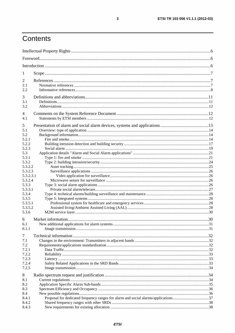
But the financial cost of this is going up. The main reason therefore is the increase in value in the contents of private households. The main cost of damages in the building sector / building alarm sector are the damages by water (broken water pipes), see Table 5.3.

ETSI
ETSI TR 103 056 V1.1.1 (2012-03) 18
Table 5.2: Crimes recorded by the police / domestic burglary, see [i.37]
ETSI
ETSI TR 103 056 V1.1.1 (2012-03) 19
Table 5.3: Damages and combined effort for the insurance companies in Germany for the year 2004 to 2006, source GDV [i.51]
Number of damages in thousands
Claims settlement in Mio € Average of one compensation in €
2006 2005 2004 2006 2005 2004 2006 2005 2004
Over household insurance
Sum 1303 1338 1426 1153 1175 1226 884 878 860
Fire 520 540 580 450 460 480 862 838 820
Intrusion 410 440 460 410 450 480 1018 1046 1045
Water 240 230 230 210 190 190 885 847 828
storm 80 70 90 40 30 30 408 360 349
Glass 30 30 50 10 10 10 267 259 275
elementary 10 10 10 10 20 10 1298 1555 1218
Over building insurance
Sum 1923 1978 2092 3165 2996 3017 1646 1515 1442
Fire 190 190 180 740 700 700 3384 3451 3653
Water 1140 1060 1020 1710 1610 1540 1411 1405 1410
storm 610 700 860 610 600 710 868 763 759
elementary 20 20 10 50 40 20 2358 2136 1668
5.2.3 Social alarm
By definition Social Alarm is responsive to incidents and occurrences that may prove dangerous for the client. It has been proved that it can reduce the consequences of falls of the elderly and help prevent adverse events in persons with Dementia.
If elderly people have heart diseases this could lead to a failure of the cardiovascular system. After 3 min without heart beat non reversible damage to the brain is to be expected. The average time in which professional ambulances will reach the emergency is 10 min to 20 min.
To minimize the risk for elderly / distressed people the traditional social alarm system [i.16] was invented, which sends out an alert in case of an emergency. As a result of the activities of social alarms service providers, over a million people in the UK currently benefit from basic telecare services. Similar numbers can be applied for other European countries.
The further development of the traditional social alarm system is the so called Telecare system, which is a combined use of home alarm and sensors. (see clause 5.3.3). Such systems become, especially as integrated systems (see clause 5.3.5), also more and more politically relevant, because the percentage of the elderly European population will increase in the coming years as shown in Figure 5.4.
The use of such systems can help deliver a range of benefits including:
• Reduce the requirement for residential/nursing care
• Reduce the burden placed on carers
• Reduce Intermediate care after hospitalisation

ETSI
ETSI TR 103 056 V1.1.1 (2012-03) 20
• Reduce acute hospital admissions
• Reduce the consequences of accidents and falls in the home
• Support hospital discharge and intermediate care
Figure 5.4: Estimated change (increase in percentage) of the elderly population (65+) in Europe till 2050
In 2030 there will be roughly two active people (15 to 65) for one inactive person (65+). By 2050 about 135 million people in the EU-25 will be older than 65 [i.20], [i.21] and [i.31]. This demographic change has, and even more will have, an enormous economic and social impact on various areas. Europe today is still ill-prepared to deal with this demographic change and the implications it will have on social, political, and economic structures.
In addition there is an increasing number of elderly people who likes to stay in their private environment. For this environment a number of technical solutions are required to support the elderly people in their demands and wishes (see Figure 5.14).
The European Commission reflected this development in a mandate for eHealth [i.24] and in the Recommendation of the European Commission 2011/413/EU [i.31]. One result of this importance for the European Community are the projects and organizations involved in Ambient Assisted Living a further development of the Telecare service (see clause 5.3.5).
NOTE: Some of the European funded projects can be found under: http://www.aal-eutschland.de/europa/projekte.
For this demands and wishes, as well as the planning of the European commission [i.31] the usage of wireless devices / technology will help to reach this demand.
One of the sub-functions of ambient assisted living, the telecare function to support elderly people with health problems is shown in Figure 5.5.

ETSI
ETSI TR 103 056 V1.1.1 (2012-03) 21
Figure 5.5: Basic principle of a telecare system
More detailed information can be read in annexes A and B.
5.3 Application details "Alarm and Social Alarm applications"
Figure 5.6: Basic alarm system principle with the basic command functions
There is a wide range of applications described in the following clauses more detail can be seen in annex A.
5.3.1 Type 1: fire and smoke
Figure 5.7 shows a typical scheme of a professional smoke / fire alarm system.
SRD technology

ETSI
ETSI TR 103 056 V1.1.1 (2012-03) 22
Figure 5.7 Scheme of a professional smoke / fire alarm system
Wireless elements in a professional smoke / fire application:
• wireless smoke/fire detectors
• wireless manual call point
• transponder
• wireless sounders / enunciators
• wireless remote keypads
• wireless image transmission (clause 5.3.2.3.1)
Wireless fire detection systems are used where cables or conduit are restricted due to structural or aesthetic reasons, or for reasons of architectural conservation. The use of wireless systems is often necessary for museums, churches or other, especially historical buildings, and many more.
Temporary installations are very easy and most efficient, especially for large tents and temporary buildings.
Such systems offer high flexibility in changing, adding or removing detection and protection elements without interruption of operation and high investment.
CEN/TC72 has already issued under the mandate M/109 of the Construction Products Directive 89/106/EEC a product standard EN 54-25 - Fire detection and fire alarm systems - Part 25: Components using radio links [i.5] and [i.18].
The aim of this European Standard is to define additional requirements to radio linked products and tests that allow radio based fire detection systems and components complying with them to be at least efficient and stable as wired fire detection systems and components complying with the current requirements of cable based systems in the EN 54 standards [i.5].
The difference between "professional" and private/residential fire system a typical private smoke and fire system is shown in Figures 5.8.
Figure 5.7 shows a residential smoke / fire system.
Wireless smoke / fire detector
transponder
wireless sounders / enunciators
wireless remote keypads

ETSI
ETSI TR 103 056 V1.1.1 (2012-03) 23
The differences between a commercial and a residential smoke / fire system are:
Residential smoke / fire detectors can work on a "self" standing mode � there is no need to work in a network. Such detector has both parts: smoke / fire sensor + alarm part included.
In this case the wireless part will be used to wake up the other sensors inside the alarm range / system only in the case of an event to use their alarm function to cover a wider area for e.g. acoustic signalling. Does this mean"sounding the alarm"?
The usage of wireless devices helps to:
• install a smoke / fire system inside existing buildings, without any cables;
• increase the alarm range (to get the alarm info everywhere in the building);
• future: implementation into a home automation network possible, e.g. � in the context of a M2M network to get the possibility to send an alarm (alarm function)and to make temperature info available (synergy function for metering, message without a low priority).
Figure 5.8a: Picture of a smoke alarm device under [i.48]
Figure 5.8b: Scheme of a residential smoke / fire system
More information can be seen in clause A.2.
Multi alarm paths (wireless)

ETSI
ETSI TR 103 056 V1.1.1 (2012-03) 24
5.3.2 Type 2: building intrusion/security
Figure 5.9: Principle of a private building intrusion / security system
Figure 5.10: Detailed overview of a complete intrusion and security system system
Information / Alarm message to a mobile device or security organization / police
detectors, sensors
human interfaces

ETSI
ETSI TR 103 056 V1.1.1 (2012-03) 25
Figures 5.9 and 5.10 describe how a building intrusion/security system may look. The system is based on different types of detectors / sensors which transmit the alert to a central unit connected to a public network thru via a transmitter. New building security systems have in addition to the intrusion function also a fire and smoke detection option (see clauses 5.3.1 and 5.3.4). In commercial and residential areas, the transmitter is connected to a surveillance centre.
In case of intrusion, the central unit sounds the siren, flashes outside the premises and sends the alert to the surveillance centre or contact the owner by phone.
Smoke and alarm detection systems have different interfaces for remote entry based on e.g. GPRS/GSM/UMTS, see figure 5.9.
The "safe" transmission / communication requirements (from the application / user side) are described in EN 50131-5-3 [i.15] (for intrusion). Typical commercial alarm sensor applications have the same basic system components as a residential system; however they utilize a larger quantity and variety of sensor devices. Typical commercial systems may have between 100 and 1 000 sensor devices, with loading data transfer of 1 communication every 200 seconds per sensor device.
Additional sensor devices:
• Wireless panic button.
• Wireless bill trap (alarms if last bill is taken from money drawer).
5.3.2.2 Asset tracking
Asset tracking is managing availability and serviceability of assets used to move, store, secure, protect and control inventory within the enterprise and along the supply chain or in conjunction with service providing.
Wireless asset tracking of goods or employees is usually organized with RFID architecture. Different type of RFID may be used depending on the specific application needs.
Figure 5.11
RFID devices usually transmit at specific frequencies described in ERC/REC 70-03 [i.1] annex 11 or a UWB physical layer [i.8] and [i.10]. Therefore, asset tracking in building is out of scope of the present document and not further considered.

ETSI
ETSI TR 103 056 V1.1.1 (2012-03) 26
5.3.2.3 Surveillance applications
5.3.2.3.1 Video application for surveillance
The communication between wireless cameras and the monitoring system for e.g. shop surveillance should go under generic regulations and standardization (e.g. EN 300 328 [i.17] or EN 300 440 [i.10] for the 2,4 GHz ISM band).
These surveillance applications are not relevant for the present document.
The view of the authors is that general purpose video surveillance should not be treated as an alarm system. But images sent as a result of an alarm trigger event could be considered as part of an alarm transmissions.
More details and information can be seen in clause A.4.
5.3.2.4 Microwave sensor for surveillance
These devices use the transmitted radio energy for sensing rather than communication. In principle, they use the Doppler radar principle to detect movement within the field covered by the electromagnetic energy.
Frequency range: 2,4 GHz, 5,8 GHz, and around 10 GHz.
In the present document there is no need for a specific frequency request for microwave sensors. The sensors can use the generic regulation for radiolocation application. Details of the possible technical parameters (frequency range,) are described in ERC/REC 70-03 [i.1] and the related harmonized standards [i.2], [i.10], [i.15] and [i.30].
This kind of sensor can be used for: Type 1 fire/smoke, details clause 6.1, type 2 intrusion, see clause 5.3.2 , type 3; social alarm, see clause 5.3.3 and type 5; integrated systems, see clause 5.3.5.
• Occupancy detection, egg., for lighting control
• Occupant monitoring, one of the Assisted Living functions
• Intruder detection
Microwave sensors may help to distinguish between human and pets in a room. When used for intrusion detection these sensors are usually combined with a PIR detector.
5.3.3 Type 3: social alarm applications
This type of application is important to help to protect human lives. As an example an elderly, unwell or distressed person with e.g. Heart disease which could lead to a failure of cardiovascular system may be assumed. After a certain time (3 min) without help non reversible brain or heart muscles damages may occur. Such system helps to minimize the direct and consequential damages to a minimum.
In future the actual social alarm applications and telecare applications can be understood as assisted living systems, which are described in clause 5.3.5 of the present document .This is based on the fact that market / users request to increase the capability and performance of the "old" traditional "push-button" applications. This will lead to a combined sensor network application including e.g. movement and temperature sensors.
For wireless social alarm systems, and also for most of the other alarm systems, the homologation framework does not take into account other then ETSI standards. E.g. in the case of social alarm an important standard for the product homologation, EN 50134-5 [i.16] requires a dedicated frequency range for the application which is in contradiction with the 2009/381/EC on Short Range Devices [i.7].

ETSI
ETSI TR 103 056 V1.1.1 (2012-03) 27
Figure 5.12: actual social alarm application
More information can be seen in clause A.5.
5.3.3.1 Private social alarm/telecare
Basic social alarm application is a combination of base station and personal sensor (body worn). It is used for elderly people to launch an alert in case of emergency. External connection may be done by phone, IP, GPRS or GSM.
Traditionally Telecare is the combined use of home alarm and sensors to provide a means of manually or automatically signalling a monitoring centre, which can then arrange an appropriate care response to the Telecare service user.
As a result of the activities of social alarms service providers, over a million people in the UK currently benefit from basic telecare services. Similar numbers can be applied for other European countries.
Telecare services are known by various names, including social or community alarm, care line or lifeline services. A telecare console is linked to the client's telephone line that enables the client to get near instant help, at the touch of a button, even if they are unable to speak.
By definition Telecare is responsive to incidents and occurrences that may prove dangerous for the client. It has been proved that it can reduce the consequences of falls of the elderly and help prevent adverse events in persons with Dementia. The use of Telecare can help deliver a range of benefits including:
• Reduce the requirement for residential/nursing care
• Reduce the burden placed on carers
• Reduce Intermediate care after hospitalisation
• Reduce acute hospital admissions
• Reduce the consequences of accidents and falls in the home
• Support hospital discharge and intermediate care
The result of using Telecare is substantial cost saving for the care provisioning services both in the socioeconomic community and in the hospital.
More information can be seen in clause A.5.
Professional versions of private social alarms are called for example "nurse call" this application will be described in clause 5.3.5.

ETSI
ETSI TR 103 056 V1.1.1 (2012-03) 28
5.3.4 Type 4: technical alarms/building surveillance and maintenance
Building surveillance is part of the global management of buildings including access control, temperature regulation, ventilation, electricity generation and consumption and also lifts and automated doors.
Building management is a set of functions like the management of vacancy, alert treatment in case of scenario, fire detection.
Typical building surveillance and technical alarms are comprised of centralized control panels which are connected to monitoring offices via wired IP, or wireless GPRS, GSM, KNX; a variety of sensor devices, and a wireless receiver for interfacing between the control panel and sensor devices. The monitoring office can be in the building or at a remote monitoring centre (figure 5.9).
Technical alarms are typically:
• flooding or leakage alert
• over temperature detection
• lift failure detection
• automated system failure alert
• abnormal event
• emergency door kept open
• pressure failure detection
More information can be found in clause A.6.
5.3.5 Type 5: Integrated systems
Recently the telecare package has been broadened to include telemedicine which involves monitoring the vital signs and health of clients in their own homes and environmental controls. The addition of environmental controls provides a strong preventative or proactive aspect to Telecare and together they deliver a truly smart home solution.
5.3.5.1 Professional system for healthcare and emergency services
Nurse calls are professional emergency call systems for healthcare and emergency services. Patient call systems are used in hospitals, nursing homes, clinics, assisted living environments and senior residences. Nurse call systems may cover small buildings up to large campus environments. Such system includes wireless pendants; call cord bed stations, corridor call lights, emergency pull devices, or other call bell devices on a wireless platform with flexible alarm notification and event escalation including notification to pocket pager, cell phone, sms texting, two way radios.
More information can be seen in clause A.7.2.
A Nurse Call systems is normally activated automatically by an alarm sensor or manually by pushing a call for help button. The alert message, together with possible corresponding data is then transmitted wireless to Relay or Main Units, which are connected to a central system were appropriate actions will be initiated. To differentiate between the importance and the actions necessary an alarm message can include more specific information (e.g. floor/room number, Timestamp, Radio Signal Quality, Local Position, kind of alert) (see figure A.17).
5.3.5.2 Assisted living/Ambient Assisted Living (AAL)
The main demand for extra functionality came from the field of social alarms. The original concept of a manually activated means of summoning help has led into the idea of assisted living residences. Increasingly sophisticated electronic devices are used to enable the elderly people to continue living independently in their own homes. Most, if not all of these devices require wireless connectivity because no "normal" home is likely to have been constructed taking such requirements into account. Examples currently deployed include fall detectors, movement detectors and devices to check on the daily routines of the building occupants.

ETSI
ETSI TR 103 056 V1.1.1 (2012-03) 29
The next step in application evolution is the inclusion of medical monitoring into the Assisted Living concept. For instance, wireless blood glucose monitors for diabetics are available. It can be expected that many more medical functions will be able to be remotely monitored in the course of time. It is an obvious step to link these into the Assisted Living system concept.
Figure 5.13
More information can be seen in clause A.7.
By 2050 about 135 million people in the EU-25 will be older than 65, see [i.20], [i.21] and [i.31].
Based on this:
• Number of people which has to or would like to stay in their private environment.
• An AAL system is requested to support the elderly people in their wishes:
- Hobbies.
- Social contact.
- Health (Telemedicine, Implants, direct contact to medical support).
- Security and Safety (Fire, Intrusion, emergency call), etc.
For this wishes of elderly people and the planning of the European commission [i.31] the usage of wireless devices / technology will help to reach this demand.

ETSI
ETSI TR 103 056 V1.1.1 (2012-03) 30
Figure 5.14: Overview of demand / wishes and possible supply for assisted living
More information can be seen in clause A.7.1.
5.3.6 M2M service layer
The main issue for the M2M service layer will be the combination of all applications in the domain of M2M (e.g. eHealth, Home automation and smart grid). TR 102 732 [i.30] describes use cases for applications, which are nearly in line with the applications described in the present document. Nevertheless, the current as well as possible new requirements of the alarm / social alarm applications need to be taken into account. Therefore the details included in the present document might be very valuable informations for the further development of the M2M standardisation.M2M standardisations needs to guarantee an efficient use of the available resources (locally and in the backbone) to guarantee the QoS (Priority and high reliability) for each service. This especially applies to alarms, social alarm and eHealth, which need high priority in the Transmission Policy.
Therefore it is recommended, that for alarm and social alarm application connected to the M2M service layer, the following additional requirements should be implemented in the M2M service layer:
• Kind of sensor (e.g. fire, intrusion, telecare):
- Frequency / Interface to be used.
• Kind of information (e.g. alarm, system check):
- Priority inculding maximum time to transmit information.
• Additional system information (e.g. request of additional information, other interfaces).
6 Market information
Fire & Smoke
Fire and smoke detectors are mandatory for public buildings. Therefore installations for public buildings represent 93 % of the market. The remaining installations are in residential areas. This market is growing 3,3 % per year.
The European fire and smoke detectors market represents 1,2 billion € with roughly 9 Million detectors.

ETSI
ETSI TR 103 056 V1.1.1 (2012-03) 31
As there are approximatly 220 million households in Europe, the listed countries represent already 120 million of them (54,5 %). More will follow. Many of these regulations require smoke alarm devices in sleeping and living rooms, which makes approximatley 4 devices resulting in a total of about 468 million devices in these countries only. In other European countries fire brigades advertiseing the benefits of such devices which creats an even higher demand for smoke alarms. Assuming that at least 20 % will use wireless networking features, a total of more than 94 million wireless smoke alarm devices will be installed during the next 5 years. A market which will generate more than 5 billion Euros for wireless smoke alarm devices within the next 5 years.
Building Intrusion / Security
Security installations in Europe represent roughly 700 000 new installations per year including 8 to 10 devices as an average including as well public and residential installations. That represents an increase of 7 million of devices each year.
There are currently 30 million installations. 25 % of these installations are based on wireless devices. Therefore the today installed basis of wireless security devices is 80 to 100 million devices.
The global European market of security represents a total turnover above 2 Billion € with a growth of 3,5 % per year (average value over the past ten years). This turnover can be split into 1 Billion € for wireless devices and 1 Billion € for related services like remote control centre.
Social Alarm
The total Western European social alarms market in 2005 was estimated to be at $220,3 million. An estimated 734 000 units were sold and the market for social alarm applications is further expected to expand of 6,1 % over the period of 2005-2012. The penetration level for these applications as part of health and social care services stands at 4,5 % among people aged 65 and above.
The social alarms market in Europe is influenced by many drivers with the key one being theaging EU population. This is evident from the growth in the elderly segment which is estimated to grow at a CAGR of 1,46 % from 2003-2006 as opposed to the negativegrowth of 0,22 % between people aged 15 to 64. This demographic trend indicates a rise in the number of dependant people aged above 65, living longer and requiring more demanding health and social care services. Rising health and social care costs to meet the increasing needs of the elderly is a major issue across all EU countries.The population of informal carers are decreasing due to migration, smaller dispersed families and also due to the declining practice of caring for the elderly within the family setting.
This trend indicates rising opportunities for Information and Telecommunications infrastructure providers, social alarm equipment suppliers and community service providers in the future.
Additional information on market size is available in [i.12], [i.17], [i.26] and [i.41].
More detailed market information is given in annex B.
6.1 New additional applications for alarm systems
6.1.1 Image transmission
At present the majority of wireless cameras are analogue. They transmit on 4 channels in the 2,4 GHz band. The cameras transmit permanently and any motion detection is done at the receiving end. Therefore they spend 23,9 hours a day transmitting the same picture. They are also not private; the neighbours may buy a receiver and can watch too, see clause 5.3.2.3.1.
In digital IP cameras the motion detection could be done at the transmitter end. The camera would only send images if a specific trigger event occurred the images could have higher resolution and be encrypted. Many more cameras could be accommodated with less use of spectrum.
In case of an alarm (intrusion, fire, Man Down) in a building or a house, today a remote monitoring centre may verify the alarm with audio listening of the premises. Remote monitoring centres are also requesting a more efficient way to confirm if there is an intrusion or an unexpected event triggered e.g. by a pet.
The new need is for low data rate video applications coupled with alarm systems and intercom system for more security. Video systems have to be digital and secured.

ETSI
ETSI TR 103 056 V1.1.1 (2012-03) 32
More information can be seen in clause A.4.
7 Technical information
7.1 Changes in the environment: Transmitters in adjacent bands
As a result of the Digital Dividend, the use of the 790 MHz to 862 MHz band is changing. Whereas previously it has been used for TV broadcasting, in many European countries it is now being allocated for mobile communications (LTE).
The earlier TV broadcasting used this band involves high power transmitters, but they are relatively few in number, in known locations and the field strength at ground level is within known limits. They have not generally been known to cause problems to SRDs in the 863 MHz to 870 MHz band.
This pattern of use will be replaced by large numbers of lower power transmitters in arbitrary locations, including mobile handheld devices. Therefore a close proximity (<1 m) between SRDs and transmitters in the adjacent band can be assumed.
Annex D contains details of the proposed LTE system and discusses possible interference to alarm systems. It is shown that separation distances from alarm receivers of 900 m for LTE handsets and 3,6 km for fixed terminals are required.
It is very likely that even Type 1 receiver (EN 300 220 [i.2]) will not be able to stay unaffected by these out of band emissions from LTE mobile devices.
These separation distances cannot be achieved in practice and it is clear that once deployment of LTE begins, alarm systems will no longer be able to operate in the 863 MHz to 870 MHz band on the same technical basis as before.
As LTE is rolled out, the already installed base of wireless alarms and social alarms systems will begin to fail.
It is also shown in annex D that the improvement in performance required for an alarm system at 869 MHz to cope with LTE has to be in the order of 45 dB. While some technological improvement can be expected for future applications, a change in this order is not considered possible in the timeframe available. Therefore new or the replacement wireless alarm installations with less performance and reliability will only be possible with one or both of the following:
1) Revised technical parameters for LTE.
2) New spectrum allocation for alarms.
7.2 Requirements/applications standardisation Wireless alarms and social alarms have several characteristics which set them apart from other SRDs. These are Data Traffic, Reliability and Latency. Performance parameters of wireless alarm and social alarm systems need also to be considered in conjunction with the safety related aspects of such applications in SRD bands and the new needs for low data rate image transmissions.
7.2.1 Data Traffic
Alarm systems are not transferring significant amounts of data. On one interpretation, the data payload of an alarm system is one bit, and the rate of sending that bit is, hopefully, very low.
Even in the simplest system, that one bit payload is generally packaged into a message of 100 bits, which does still not amount to a large traffic if it is only sent in the alarm condition.
Most systems, however, send routine supervisory and administration messages and are monitoring not just for an alarm condition, but also for fault conditions and for tampering and interference. In some cases it is a requirement set by product specific standards (e.g. in Germany VdS 3515, France NF A2P [i.14]).

ETSI
ETSI TR 103 056 V1.1.1 (2012-03) 33
Suppose a system has 20 nodes and each node sends a test message each hour, then there are 20 messages per hour. This example would be background traffic of 2 000 bits per hour. Other systems might have higher background traffic; nevertheless this is a low level of data traffic compared to many other wireless SRD applications.
In an alarm condition, the data traffic is likely to be much higher. The level will depend on the system design, and the system will have been designed with the channel and bandwidth capacity in mind.
7.2.2 Reliability
Every application will insist it needs reliability, but the requirements for alarms are of a higher order than most of them. An alarm system is required to simultaneously have a low False Alarm Rate (FAR) and a low Missed Alarm Rate (MAR). A typical requirement might be for a system to demonstrate a FAR of less than one per year. Typically this may require the error rate of a given operation to be of the order of 1 in 10 000 to 1 in 100 000. In the example above of a 20 node system with hourly checks, there are 175 000 test messages per year [i.5].
This level of reliability cannot be achieved by the radio channel alone. It requires a system level approach in which errors and problems reported by the radio link are processed by higher layers. Nevertheless the performance requirement of the underlying radio channel is severe.
7.2.3 Latency
Latency is the measure of how quickly a message is transported to the destination. Wireless devices that interface directly with an operator, such as remote controls, may require latencies of less than 100 ms. For many other applications; latency is not a particular requirement.
At first glance, alarm systems would appear to require low latency. In practice, they can generally tolerate latencies of a few seconds, which gives the opportunity for a complex transaction rather than the sending of a single wireless message.
Reliability and Latency are interrelated. One way of expressing the requirement of an alarm system is to say, for instance, that it requires a message to be transferred and received with a probability of success of 99,99 % in 3 seconds [i.5].
7.2.4 Safety Related Applications in the SRD Bands
There is a long standing discussion about whether certain applications should operate in shared spectrum.
For example, when a manufacturer claims his application has critical implications, such as protecting property or lives, and then asks for some special treatment from the regulators, the response is often to question whether it should in that case be in the SRD bands at all.
On the other hand, if an SRD is capable of saving a life or property, why should it not be allowed to? Why in fact, should it not be assisted rather than obstructed in so doing?
It is acknowledged that a wireless alarm can never be 100 % reliable, and that an SRD one may be less reliable than one on a private frequency. But the fact that something can not 100 % reliable does not make it useless, or ineffective, and it is certainly not a reason for rejecting it or for taking actions that make it less reliable.
Wireless alarms in the SRD bands is a mature and well established industry. The better devices have achieved performance and reliability that has been found acceptable, and have achieved market success.
What is required is a partnership between industry and regulators, so that if this year, the overall reliability of wireless alarms is, say, 99 %, then next year it is 99,1 % rather than 98,9 %.
Where a particular application has a requirement for high performance, it is expected that the equipment should be designed so that it can achieve that performance. It is then entirely appropriate that the spectrum access rules be framed so as to make that possible.

ETSI
ETSI TR 103 056 V1.1.1 (2012-03) 34
7.2.5 Image transmission
For the validation of an intrusion or a technical alarm, a frame rate of 10 pictures per second may be sufficient. A sequence restricted to several frames should be considered a data transmission rather than streaming video. A maximum of 300 s per hour of transmission may be sufficient to confirm an alarm. This leads to a maximum duty cycle of 8 % over one hour but with an occurrence of once a year for one location. Therefore the equivalent average duty cycle over one month is 0,01 %. The 0,01 % is not defined as a DC over time interval (1 h, 1 month, 1 year). So definition of a pattern is important to define coexistence rules.
In case of higher rate requested, the solution is to use 2,4 GHz solutions for video surveillance.
8 Radio spectrum request and justification
8.1 Current regulations
Figure 8.1: Overview current regulation in the range 863 MHz to 870 MHz
Figure 8.1 is a depiction of the current 863 MHz to 870 MHz allocation, based on ERC/REC 70-03. There is considerable complexity in the allocations, which are spread across several annexes 1, 5, 7, 10 (etc.) of ERC/REC 70-03.
Details / Tables with for the current regulations are attached in annex D (Tables D.1 to D.3) to the present document.
ERC/REC 70-03 [i.1] is the agreed position among the CEPT member countries. It is however, a Recommendation and therefore not mandatory, which means there is variation in implementation between countries.
For EU member states, the EC Decision on SRDs [i.6] and [i.7] is mandatory. Member states must permit the allocations listed in it. They may be more permissive in allowing other uses of the spectrum, but they may not be more restrictive.

ETSI
ETSI TR 103 056 V1.1.1 (2012-03) 35
Equipment placed on the market in the EU is usually conforming to Harmonised Standards. In practice, much of the technical detail of spectrum allocations is therefore contained in ERC/REC 70-03 and in the Harmonised Standard rather than in member states' radio regulations.
In any case the requirements of the R&TTE Directive [i.12] have to be met.
For instance, Table 5 of EN 300 220 [i.2] contains a listing of SRD allocations up to 1 GHz, including the alarm sub-bands in 868 MHz to 870 MHz.
Details are provided in annex D.
For RF surveillance sensors in the intrusion application annex 6 of ERC/REC 70-03 is relevant. For integrated system application there is in addition the need to use communication equipment. The technologies used are mobile (GSM, UMTS), cable (PLC, ISDN, DSL), DECT and PMR.
For this aspect there is no need to change the existing regulation.
8.2 Application Specific Alarm Sub-bands Annex 7 of ERC/REC 70-03 [i.1] and the European commission decision [i.7] lists a set of sub-bands within 868 MHz to 870 MHz for alarms. The original intention was that these would be for high specification narrow band equipment and exclusively for alarm systems. Or rather, that other SRDs would be excluded; non SRD users of the spectrum, there for legacy or other reasons, could not be so restricted.
The recommended exclusivity of the alarm sub-bands has, however, been compromised. The UK and Netherlands (and possibly others in the future) have been more permissive than the EC Decision and permitted non specific use (band g in ERC/REC 70-03 annex 1) across the whole of 863 MHz to 870 MHz, including the alarm sub-bands.
In this regard, it is noted that the guidance from the EC to CEPT on the 5th update of the EC Decision on SRDs [i.33] contains a strong presumption against application specific sub-bands.
Application specific bands can serve a number of purposes:
1) They limit the numbers, or the density of devices using the band.
2) They can segregate different types of signals e.g. high duty cycle and low duty cycle signals are separated, which is necessary for spectrum sharing.
3) They can segregate systems according to need e.g. Systems requiring low latency do not have to compete for spectrum access with other systems.
On the other hand, there are arguments against application specific sub-bands:
1) They do not guarantee exclusivity. As mentioned above, only other types of SRDs which are under ERC ERC/REC 70-03 [i.1] can be excluded.
2) They may not be enforceable in practice. In the case of alarms, there is no proper definition of an alarm and many types of device could declare themselves as "alarms". The picture is further muddied by devices that are sometimes alarms and sometimes not, such as image transmitters.
3) Segregating signals by type is better done directly by means of signal parameters. High and low duty cycle signals can be separated without reference to application.
4) In the case of alarms, the numbers and density argument is weakened by the expected large increase in wireless alarm devices.
5) It is swimming against the regulatory tide, as discussed above.
Taking all this together, the alarms industry accepts that the case for further segregation or special treatment according to application is weak, but the case for special treatment according to need is, however, very strong.
The existing alarm allocations in 868 MHz to 870 MHz should be protected to help the continued operation of the installed base.

ETSI
ETSI TR 103 056 V1.1.1 (2012-03) 36
For newer systems, the industry request is not for spectrum for alarms, but for spectrum in which alarms can function. What is needed is not sub-bands exclusive to alarms, but sub-bands in which low duty cycle, low latency, high reliability signalling is possible.
8.3 Spectrum Efficiency and Occupancy ITU-R Recommendation SM.1046-2 [i.43] (Definition of spectrum use and efficiency of a radio system) recommends that any comparison of spectrum efficiencies should be performed only between similar types of radio systems providing identical radio communication services as explained in paragraph 4 of annex 1.
It is important, especially for systems such as alarms, not to confuse spectrum efficiency with spectrum utilisation or channel occupancy. Indeed the alarms industry is concerned about the interpretation of the measurement results from the ECC 863 MHz to 870 MHz monitoring campaign done by ECC WG FM PT 22 [i.29]. In these reports, sections of the band are classified according to occupancy, with no allowance for the different uses. Congestion of the (alarm-) subbands are only assumed when the occupancy exceeds 50 %.
Alarms are expected to deliver very high overall system reliability. In order for this to be achieved, the requirement to the radio link to deliver a certain minimum reliability is high (95 %). In practice this means that the probability that an individual transmission suffers a collision with another signal has to be below approximately 5 %.
Most alarm systems make very low duty cycle transmissions. They are often also restricted by battery power considerations. It is not generally possible, or worthwhile, to use complex spectrum access or networking control techniques. The only way, therefore, to achieve the required low collision probability is to operate in a channel with low occupancy.
It is shown in clause C.3 that to keep the collision probability below 5 % requires the channel occupancy to be below 2,5 %.
A typical single alarm sensor has a duty cycle well below 0,1 %. For instance, three transmissions of 120 ms per hour is a duty cycle of 0,01 %. A single channel can therefore accommodate 250 such devices in a single location.
Where alarms are concerned, spectrum efficiency evaluation in terms of numbers of devices served, or of the geographical density of systems and not in terms of spectrum occupancy, is necessary.
8.4 New possible regulations The existing regulatory framework (ERC/REC 70-03 [i.1]) and the related harmonized standardization (EN 300 220 [i.2]) takes into account the different types or groups of applications with similar requirements on a technology neutral basis in the band 863 MHz to 870 MHz. This takes into account the different requirements for an optimal reliability of data transmission.
Social alarm and alarm applications have a specific significance among SRDs because these applications help to protect human life and improve security and safety.
If social alarms and e.g. audio applications are allowed to use the same frequency resources the audio application with a DC of 100 % may block the social alarm totally. It has to be mentioned that the receiver of social alarm systems very likely uses already technical parameter which corresponds to the stringent receiver category1 (EN 300 220 [i.2]).
The Commission of the European Communities recognized the growing importance of such kind of alarms and decided in 2005/928/EC [i.44] to allocate in addition to the UHF range, two channels in the 169 MHz band exclusively for social alarms.
Due to physical constraints in that band (no effective antennas possible for body worn equipment (2 m wavelength) and high power consumption for these battery powered devices) these frequency range around 169 MHz was not very usable for alarm devices and the market uptake is low. Based on that there is actual an ECC questionnaire for the future 169 MHz usage. But for alarm devices it is not an option, based on the physical parameters (antenna size, power consumption) as it was expected in the past. More information are included in annex F.
The importance of these applications and the argument in (2005/928/EC [i.44]) is independent of the frequency band and still valid today.

ETSI
ETSI TR 103 056 V1.1.1 (2012-03) 37
8.4.1 Proposal for dedicated frequency ranges for alarm and social alarms/applications
Table 8.1: Proposed frequency allocation for alarm/social alarm application (dedicated ranges)
Frequency Band
Power Duty cycle
Channel spacing
Former ECC/ERC Decs
Notes
868,6 MHz to 868,7 MHz
25 mW e.r.p. < 1,0 % [Note 3]
25 kHz ERC DEC (01)09 [i.52]
The whole frequency band may also be used as 1 channel for high speed data transmissions
869,250 MHz to 869,400 MHz
25 mW e.r.p. < 1.0 % Note 3
25kHz ERC DEC (01)09 & ERC DEC (05)02 [i.53]
Former band b and e from ERC/REC 70-03 annex ; The whole frequency band may also be used as 1 channel for high speed data transmissions
869,650 MHz to869,700 MHz
25 mW e.r.p. < 10 % Note 3
25 kHz ERC DEC (01)09
869,200 MHz to 869,250 MHz
25 mW e.r.p. < 0,1 %/hr 25 kHz ERC DEC (97)06 [i.54]
Social Alarms
875,6 MHz to 876 MHz Note 1
25 mW e.r.p. Note 2 Note 3
No spacing
See Proposal TR 102 649-2 [i.28], band g6, TS 102 887 [i.45] and, studies in ECC project team SRD-MG
NOTE 1: Band edges in compliant to smart metering TS 102 887 and the GSM-R canal plan. The compatibility with IEEE 802.15.4g [i.46] is described in TS 102 887 [i.45].
NOTE 2: A DC pattern must be defined in order to coexist with GSM-R. NOTE 3: Indicative DC:
• Max Transmitter On Time / per single transmission: [700 ms] • Min Transmitter Off Time between two transmissions: [400 ms] • Sum of Ton times / minute = DC/min [2,5]%/min • Sum of Ton times / hour = DC/hr: [0,1]%/hr
The DC / LDC requirement will be studied (frequency range depended) in two new work items in ECC PT SE24 (Start October 2011): • ECC SE24 workitem 41: SRDs in the bands 870 MHz to 876 MHz/915 MHz to 921 MHz • ECC SE24 workitem 42: Improvements for SRDs in 863 MHz to 870 MHz • It is planned that both work items will have an ECC report in 2013.
The request for an additional dedicated frequency range (875,6 MHz to 876 MHz) could be read in conjunction with clauses 8.2 and 8.3. Dedicated in that frequency range does not necessarily mean exclusive. What it means is that this frequency range will be managed so that low duty cycle, low latency, high reliability devices, such as alarms, can operate in them.
In practice this means setting the access conditions so that the occupancy is kept below 2,5 %. Ways of achieving this include:
1) setting technical parameters such as duty cycle or transmission length in legislation
2) setting technical parameters in harmonised standards
3) restricting the band to certain applications
A pragmatic approach may involve using all these tools initially until studies show which ones can be dropped.
For the other existing frequency ranges in 863 MHz to 870 MHz the allocations should remain exclusive to alarms.

ETSI
ETSI TR 103 056 V1.1.1 (2012-03) 38
8.4.2 Shared frequency ranges with other SRDs
Table 8.2: Proposed frequency allocation for alarm / social alarm application (shared ranges)
Frequency Band
Power Duty cycle
Channel spacing
ECC/ERC Decs Notes
A1 865 MHz to 868 MHz
100 mW e.r.p. < 1,0 % No The whole frequency band may also be used as 1 channel for high speed data transmissions, sharing with RFID equipment ERC/REC 70-03 annex 11
A2 863 MHz to 865 MHz
100 mW e.r.p. < 1,0 % No The whole frequency band may also be used as 1 channel for high speed data transmissions, sharing with audio equipment ERC/REC 70-03 annex 13
A3 915 MHz to 915,2 MHz
Note 1
25 mW
e.r.p. 1 % Note 1 Note 2
A4 920,8 MHz to 921,0 MHz
25 mW e.r.p. 1 % Note 1 Note 2
NOTE 1: Bandedges in compliant to smart metering TS 102 887 [i.45] and the GSM-R canal plan. The compatibility with IEEE 802.15.4g [i.46] is described in TS 102 887 [i.45].
NOTE 2: It is necessary to define a DC pattern to guarantee intra SRD coexistence.
As far as digital image transmissions are concerned as an alarm system, the most suitable candidate bands seem to be:
• 863 MHz to 865 MHz as such bandwidth and permanent transmissions are already allowed. The increase of power has to be studied.
• 865 MHz to 868 MHz as such high power and duty cycle are allowed by EC SRD Decision for RFID. Coexistence with RFID has to be studied.
8.4.3 New requirements for existing allocation
LDC as a sharing requirement is discussed in ETSI STF 411. This might be a possible requirement for the existing and possible new (> 873 MHz) alarm bands instead of the existing DC. LDC might give the possibility to share the frequency range with GSM-R or to increase the spectrum efficiency in the alarm frequency ranges.
In addition to have the possibility to share frequencies with audio and RFID applications (see Table 8.2, bands A1 and A2) it could be necessary to define an alarm system specific LBT function.
8.4.4 Other frequency ranges / technologies
This solution do not present advantages for the customer as there is a need to have a second transmitter in the hardware, therefore the price of hardware will be at minimum doubled.
This additional frequency ranges / technologies will be used if there are specific applications requirements, like correct object position in the system environment.
Possible additional frequency ranges, without any exclusivity for alarms.
8.4.4.1 L-Band (1,4 GHz)
For imaging transmission in the L-Band (1,4 GHz) under PMSE regulation. This possible usage is open based on the actual ECC discussion about a primary usage for this range. In the year 3Q 2011 the ECC discussions started Project team FM 50.

ETSI
ETSI TR 103 056 V1.1.1 (2012-03) 39
8.4.4.2 UWB below 10,6 GHz
The UWB technology is very advantageous for the tracking function in the assisted living application or for short range communication. This technology can be used under the generic and specific location tracking ECC and EC UWB rules [i.8].
9 Main conclusions Wireless Alarms and Social Alarms provide a large economic and social benefit. The number of wireless alarms and social alarms the benefit to European society is set to grow dramatically, not least because of an ageing population.
The vast majority of wireless alarms operate in the 863 MHz to 870 MHz SRD band. They are subject to the SRD rules, which include the requirement of spectrum sharing with all comers and expect no special protection against interference. This would seem to be an anomaly for systems claiming to protect lives and property, but it is a scheme that has worked very well for many years.
The needs of wireless alarms and social alarms can continue to be met under the licence-exempt SRD regime if certain changes are made.
For traditional wireless alarm and social alarm functions, that is, communicating a warning from a remote sensor to a central control, the total spectrum requirements are not great.
What is required for this purpose, is a set of small sub-bands in the UHF region. For these particular bands, it is necessary to challenge the presumption that higher occupancy equates to better use. The conditions for these sub-bands should instead be set so as to ensure a low occupancy, less than 2,5 %.
Because of the possibility of interference, for instance from LTE, frequency diversity is required. There should therefore be a set of bands - four within 863 MHz to 870 MHz (existing allocation) and one close to 876 MHz, and two in 915 MHz to 921 MHz.
An increase in alarms traffic is expected, not only because of the increased number of alarms but because of extra functionality, reporting and housekeeping requirements, and a move to bi-directional signalling. Alarms, however, remain essentially low traffic systems.
There are new functions requested of alarms, such as image transmission. These require higher data traffic, but only intermittently. To the extent that they cannot fit within the alarms and social alarm sub-bands, they may be accommodated by some parameters modifications to share with existing SRDs sub-bands. For example sharing with Audio [863 MHz to 865 MHz] or with RFID [865 MHz to 868 MHz] can be studied.
10 Requested ECC and EC actions The present situation is that wireless alarm and social alarm systems in the SRD bands are well established, have an accepted performance and reliability today and provide therefore a valuable service. The request from industry is that actions should be taken to ensure that:
a) Wireless alarms and social alarms can continue to complete their mission in the way established for many years.
b) New functions will be added in the near future, such as ambient assisted living, improved medical monitoring, and image transmission. This requires a new regulatory framework.
There are several threats to the alarm and social alarm systems that need to be addressed:
1) There is a large increase in the number of wireless devices, which will lead to congestion in the existing allocations for alarms and social alarms. This is compounded by a poor definition of "alarms" that could allow a wide range of devices into the existing allocations.
Requested action: A clear and detailed definition of Alarms/social alarms should be given that reflects the social economic importance of these application and therefore keep the dedicated bands / the existing status in the range 863 MHz to 870 MHz.

ETSI
ETSI TR 103 056 V1.1.1 (2012-03) 40
2) Due to the increasing number of wireless alarm and social alarm devices, accompanied by new integrated alarm and social alarm systems, such as ambient assisted living, improved medical monitoring, and image transmission there is a need for additional frequency bands.
Requested action: A mandate to CEPT WGSE should be given to start studies on new frequencies for alarms and social alarms in the UHF bands 873 MHz to 876 MHz (875,6 MHz to 876 MHz) and 915 MHz to 921 MHz (915 MHz to 915,2 MHz and 920,8 MHz to 921 MHz).
3) The currently existing spectrum access and sharing arrangements are not sufficiently defined. To increase the spectrum efficiency a flexible DC scheme could be useful for dedicated bands. This would improve the sharing of frequency ranges with other SRDs, RFIDs and GSM R.
Requested action: A mandate to CEPT WGSE should be given to study classes of Duty Cycle parameters.
Due to the deployment of LTE (see clause 6.1 and annex D) wireless alarm and social alarm systems will be harmed by interference caused by LTE systems. This could lead, in worst case, to the situation that wireless alarm and social alarm systems cannot operate anymore in the SRD bands next to LTE bands.
Requested action: A mandate to CEPT WGSE should be given to study the impact of LTE on SRD in the bands 863-870 MHz and 870 MHz to 876 MHz and define appropriate technical requirements for coexistence.
11 Expected ETSI actions 1) A NWI for an ES, specific for alarm and social alarm applications, should be created. This ES is intended to be
later developed into an HEN if requested by stakeholders and/or if there is a need due to dedicated sub-bands.

ETSI
ETSI TR 103 056 V1.1.1 (2012-03) 41
Annex A: Detailed application information
A.1 Overview of types for social alarm and alarm applications
In this annex there is additional application information. This annex is in addition to clause 5.
1) Fire and smoke (clause A.2)
2) Intrusion / security (clause A.3)
3) Image transmission (clause A.4)
4) Social alarm (clause A.5)
5) Technical alarms / building surveillance (clause A.6)
6) Integrated systems (clause A.7):
- Ambient Assisted Living (clause A.7.1):
- Personal location information / example "nurse call" nurse call (clause A.7.2).
A.2 Type 1 fire and smoke
A.2.1 Background information and motivation. Due to the fact that many historic buildings need intensive fire protection and wiring cannot be installed due to architectural reasons, wireless systems are often the only means of enhancing the fire safety of the building structure and visitors of such historic buildings. This is valid of older public buildings in general.
In addition, smoke detectors will become mandatory in most of the houses or flats in 2015 in Europe.
Figure A.2.1 shows a typical Fire Brigade view of the alarm sequence.
Figure A.2.1: Fire Brigade view of the alarm sequence

ETSI
ETSI TR 103 056 V1.1.1 (2012-03) 42
A.2.2 Detailed application description Figure A.2.2 shows a typical scheme of a fire alarm system.
Figure A.2.2: Overview professional fire alarm system
Elements in a smoke / fire application:
• wireless smoke / fire detectors
• wireless manual call point
• transponder
• wireless sounders / enunciators
• wireless image transmission (clause 5.3.2.3.1)
Typical professional application (EN 54-25 [i.5]):
Figure A.2.3: Overview professional system
RF - Link

ETSI
ETSI TR 103 056 V1.1.1 (2012-03) 43
For the private environment smoke devices (detector + sounder) see figure 5.8a are standardized under EN 14604 [i.3] and [i.32].
Due to the specified functional safety level the maximum number of devices per gateway should be less than 32. As detection zone in most cases is restricted to one floor or part of one floor of a building, usually less than 1 600 m².
The gateway (master) wired to a fire detection and alarm control and indication equipment, polls its registered detectors (slaves) within a defined time on a defined base frequency channel. In case of no response, the master will change to a defined alternative channel and will try again. If most available generic SRD channels will be blocked, the only alternative channel to be used by such a system will be one within the alarm bands.
EN 54-25:2008 [i.5] defines a reaction time of e.g. 10 detectors are going to alarm stage, that the first alarm message shall be indicated within 10 s and the last alarm message within 100 s. No alarm message shall be lost.
A.2.3 Typical usage time and traffic evaluation of such device Activity factor of a device / system:
• A fixed safety monitoring system, will always be in the operation mode. There is an requirement for an transmission fault detection within 300 s a reported within 100 s by the gateway to the control and indication equipment.
A.2.3.1 Size of Alarm systems
Professional Systems: a system with 30 up to 500 wireless nodes / sensors is possible.
Residental / Provate Systems: up 20 wireless sensors.
A.2.3.2 specific DC requirement for huge systems / networks
For automatic systems with 500 or more devices / sensors it is very important that if there is an acknowledgement required, the additional transmitter on-time from the hub / basestation should be included to the On-Time of the single device, see therefore in additional EN 300 220 [i.2], clause 7.10.2.
A.3 Type 2: building intrusion and security Application overview / keywords under this category:
• Intrusion / security networks;
• Asset tracking;
• RF surveillance sensors.
A.3.1 Background and justification Due to the fact that in many houses or buildings it is easier to install a wireless alarm system and intrusion grows from at least 10 % per year, wireless alarms are very popular.
In addition, smoke detectors will become mandatory in each house or flat in 2015 in Europe [i.32] and [i.35].

ETSI
ETSI TR 103 056 V1.1.1 (2012-03) 44
A.3.2 Detailed application description Typical residential alarm systems are comprised of a control panel which connects to external monitoring offices via GPRS, GSM or IP; a variety of sensor devices, and a wireless receiver for interfacing between the control panel and sensor devices.
Common sensor devices in an intrusion / security network:
- Wireless smoke detectors
- Wireless heat / fire sensor
- Wireless intrusion / movement sensor
- Wireless glass break detectors
- Wireless vibration sensor
- Wireless door / window magnetic contacts
- Wireless PIR motion sensors
- Wireless PIR & Microwave motion sensors (clause 5.3.2.4)
- Wireless sounders / enunciators
- Wireless sirens / strobes / relays
- Wireless Key Fobs
- Wireless image transmission (clauses 5.3.2.3.1 and A.4)
Figure A.3.1: Principle of the in building part of intrusion system
Typical residential alarm systems have fewer than 40 to 50 sensor devices. Worst case theoretical communication load happens if all sensors alarmed at one time, while typical communication load is 1 communication every 15 minutes per sensor device. A figure with principle system architecture is shown in figure A.3.2.

ETSI
ETSI TR 103 056 V1.1.1 (2012-03) 45
Figure A.3.2: Principle overview of a building security system
A.3.3 Typical usage time and travel evaluation of such device A fixed intrusion system, in operation mode checked the at fixed time interval within typically 15 minutes. Before to send an alert, several pre-alarm levels have to be reached. The quality of a system will depend on its capacity to discriminate a false alarm from a real intrusion.
For intrusion systems / sensor networks an acknowledgement is required (function, safty reasons and to reduce the false alarm rate), the additional transmitter on-time from the hub/basestation should be included to the On-Time of the single device / sensor, see therefore in additional EN 300 220 [i.2] clause 7.10.2.
A.4 Image transmission Three main kinds of applications can be described:
• Video integrated with detectors
• Intercom system
• Stand alone camera for security system
A.4.1 Background and justification Due to the fact, that in many houses or buildings a wireless system is easier to install than a wired one, and intrusions grow at least 10 % per year, wireless alarms are very popular. Image transmission systems are heavily used in a building intrusion / security system (see clause A.3).
Information / Alarm message to a mobile device or security organization / police
detectors, sensors
human interfaces

ETSI
ETSI TR 103 056 V1.1.1 (2012-03) 46
A.4.2 Detailed application description Installation of wireless cameras for security
Figure A.4.1: Principle for a wireless image transmission system
Wireless intercom
Figure A.4.2: Principle for a wireless image intercom system
A.4.3 Typical usage time and traffic evaluation of such device For imaging transfer, the activity factor may be very low. It should not occur more than once a year.
When transmission occurs it can have a maximum duration of 300 s per hour.

ETSI
ETSI TR 103 056 V1.1.1 (2012-03) 47
A.5 Type 3: social alarm applications Application overview / keywords under this category:
- Medical alert
- Private social alarm / telecare
- Lone workers / man down
A.5.1 Background and justification Social alarms are today considered as a solution that will have a major influence in the coming years due to population ageing.
In case of an emergency (a fall, chest pains, suspected intruder, etc.), the user simply calls for help by pressing the button on the radio transmitter or the system can decide for itself after a sensor is operated to call automatically.
A.5.2 Detailed application description
A.5.2.1 Private social alarm / telecare application
Figure A.5.1: Principle for a typical social alarm system
Basic social alarm application is a combination of base station and personal sensor (body worn).
Actual social alarm system / basic telecare functionality could include following wireless sensors:
• Wireless hand alarm transmitter
• Social alarm watch with transmitter
• "falling sensor" � dead men position / ManDown function
• Wireless alarm sensor for push/pull usage (bathroom)

ETSI
ETSI TR 103 056 V1.1.1 (2012-03) 48
• Wireless contact transmitter
• Wireless movement sensor (microwave, see clause 5.3.3.4)
• Wireless gas sensor
• Wireless temperature sensor
• Wireless water sensor (running water)
• Wireless smoke / fire video (see clause 5.3.1)
NOTE: External connection via: e.g. telephone line, GPRS, GSM, cable.
A.5.3 Typical usage time and traffic evaluation of such device For all kind of social alarms the key is the latency, therefore there is a need to have a spectrum as free as possible to be sure that the message can be sent immediately.
Today frequency arrangement with specific frequencies for social alarms is good and strongly supported by all members of this industry.
A.6 Type 4: technical alarms / building surveillance
A.6.1 Background and justification Building surveillance and technical alarms are mandatory in large building.
For residential areas, it brings a high level of comfort for the user especially when being outside of the house.
A.6.2 Detailed application description
Figure A.6.1
Typical building surveillance and technical alarms are comprised of centralized control panels which connects to monitoring offices via wired IP or wireless GPRS, GSM, KNX; a variety of sensor devices, and a wireless receiver for interfacing between the control panel and sensor devices.

ETSI
ETSI TR 103 056 V1.1.1 (2012-03) 49
Specific sensors for technical alarms:
• Wireless water sensor (indoor flooding )
• Wireless door / window magnetic contacts for emergency exits
• Wireless magnetic actuator for doors to stop fire
• Wireless motion detectors
• Wireless temperature detectors (freezers)
• Wireless temperature sensor
• Wireless electricity failure detectors
A.7 Type 5 integrated systems Today the trend for professional systems is to have a fully integrated solution for the customer including fire, security and telecare.
A.7.1 Ambient Assisted Living
A.7.1.1 Background and justification
For the customer, such solutions are attractive due to the high level of interworking reached. However, +the configuration might be more complex than independent systems.
• Demographic change: see [i.31], [i.20], [i.21], [i.22] and [i.19].
Detailed information to AAL.
Overview European funded projects: http://www.aal-deutschland.de/europa/projekte
European: Ambient Assisted Living Joint Programme: http://www.aal-europe.eu/
Continua Health Allianz: http://www.continuaalliance.org/index.html [i.23]
EC-Mandate: Mandate M-403: eHealth Interoperability [i.24].
Organization UK: http://www.telecare.org.uk/
With such systems also the cost can be reduced [i.20].

ETSI
ETSI TR 103 056 V1.1.1 (2012-03) 50
Figure A.7.1: Reducing costs and improving quality of life
Wishes of elderly people:
Figure A.7.2: Wish of elderly people on a assisted living system

ETSI
ETSI TR 103 056 V1.1.1 (2012-03) 51
A.7.1.2 Detailed application description
Following figures are showing the principle of an assisted living / home care application.
NOTE: A medical healthcare system has typically two communication possibilities - daily monitoring (normal monitoring / status of the person), measured values / info will send to a "base
station and then stored or send to the "doctor", not time critical; - alarm situation/time critical.
Figure A.7.3: Principle of a home care solution application
(Social) alarm application / function � time critical
SRD technology Daily monitoring information / date � not time critical

ETSI
ETSI TR 103 056 V1.1.1 (2012-03) 52
Figure A.7.4: Typical telehealth system (extracted from [i.22])
Or another picture taken from the continua alliance [i.22].
Figure A.7.5: Typical telehealth system from Continua
Ambient Assisted Living / Telecare Functionality could include a combination of Sensors dependant on needs but typically the main Radio sensors are as follows:
• Radio personal pendant alarms
• Radio Smoke Detectors
• Radio Heat Detectors

ETSI
ETSI TR 103 056 V1.1.1 (2012-03) 53
• Fall detectors
• Radio Pullcords
• Radio Movement sensors i.e. PIR's
• Radio Natural Gas Sensors
• Radio Temperature Sensors (Heat Extremes) High / Low
A possible system implementation, with a maximum of Sensors is shown in figure A.7.6.
The combination of sensors from the type of applications, described in the present document "alarm", "social alarm", "building alarm", tracking applications [i.11] and Generic SRD ([i.1], [i.2], [i.8], [i.10], [i.11] and [i.17]) for e.g. metering or energy control [i.28] and other wireless technologies is very close to a fully automated home. This common usage of information between applications will also discuss under the key word: Machine to Machine (M2M), see also clause 5.3.6. In ETSI TC M2M, there is also a work item it describe a use-case for eHealth [i.24].
Figure A.7.6: Principle implementation of sensors for an assisted living area
In addition to the above Manual / Automatic Radio sensors, Activity of daily living is a proactive system that can view client behaviour and predict potential problems before they occur. The home hub unit receives radio messages from specific Telecare sensors, i.e. PIR activations, in/out of bed, kettle on/off, water usages etc and this data is sent to a server overnight. Carers can view the data from a normal browser and email alerts can automatically be generated if activity patterns deviate from normal.
A.7.2 Personal location information / example "Nurse call" A Nurse Call is based on a general principle of operation for a personal location information system . But only two systems have a kind of alarm function.
System 1: man down, but such a system is more based on a communication system like dect.
System 2: personal location system in "critical environment", like jail and hospitals.

ETSI
ETSI TR 103 056 V1.1.1 (2012-03) 54
The critical system based on alarm time is the personal location system in the clinical environment.
Such a system can have up to 500 transmitters.
Figure A.7.7: Parts of a an nurse call / personal alarm system
1) An alarm or a call for help is activated on a NurseCall device.
2) Alarm is sent by radio-transmission to the central system: Main Unit or Relay Unit.
3) The Main Unit or Relay Unit receives the alarm through its antenna.
4) The Red button and the LED Indicator are blinking.
5) An additive signal indicates that an alarm is received.
6) A visual signal can be activated.
7) The Main Unit or Relay Unit shows Alarm/Event corresponding data.
8) The list of Alarms/Events can be transferred from Main Unit internal buffers to a computer, and then printed.
Example for a NurseCall application
Several NurseCall possibilities.

ETSI
ETSI TR 103 056 V1.1.1 (2012-03) 55
Figure A.7.8: Several NurseCall possibilities
From figure A.7.8:
Following sub application scenarios / situations can be defined:
• mobile call for help
• room call for help
• Location mode (sensor in combination with a magnetic field)
• Dementia mode (door sensor and/or with a magnetic field sensor) + accompany mode (the presence of e.g. nurse is detected
• Man Down function
To differentiate between the situations and the importance an alarm/messages can include following identification / information:
• Identification of Alarm/Message
• Floor number / room number / bed number or a single number
• Date and time
• Quality of radio signal received
Nurse support request
Man Down
Localisation function / area localisation
„normal“ support or alarm patient

ETSI
ETSI TR 103 056 V1.1.1 (2012-03) 56
• Storage type (Alarm or Event)
• Identification of the unit receiving the Alarm/Message (Main/Relay)
• Local position if Locating Mode is selected
Comments: In regulation/standard (EN 54-25 [i.5]), there are conditions of 3-years life time of a battery.
I add "in normal operation" and add the notes "Referring to clause 5.3.2 of EN 54-25" because battery life time could be significantly varied in alarm and fault situations.
Other example for a nurse calls system. In this system there is a combination of "SRD communication" and DECT used.
Figure A.7.9: Example for an nurse call application

ETSI
ETSI TR 103 056 V1.1.1 (2012-03) 57
Annex B: Detailed market information
B.1 Type 1 fire and smoke The European fire and smoke detectors market represents 1,2 billion € with 9 M detectors.
This market is divided amongst the following countries.
Table B.1.1: Market numbers fire and smoke
Country Value Number of installations per year
Europe 1 200 M€ +3,3 % per year
UK 227 M€
France 177 M€
Germany 255 M€
Italy 106 M€
Spain 109 M€
Benelux 151 M€
Scandinavia 86 M€
Others 71 M€
Installations are sold thru several distribution networks:
• Installers
• DIY
• Wholesalers
• Directly to the user
B.2 Type 2: intrusion and security The European security market for devices represents 1 Billion €.
This market is divided amongst the following countries.

ETSI
ETSI TR 103 056 V1.1.1 (2012-03) 58
Table B.2.1: Market numbers intrusion and security
Country Value Number of
installations per year
Wireless devices Residential devices
Europe 1 000 M€ +3,5 % per year
50 %
UK ~200 M€ 600 000 40 % 70 %
France 116 M€ 158 000 67 % 72 %
Germany 144 M€
38 000 32 % 33 %
Italy 166 M€ 220 000 40 % 60 %
Spain 55 M€ 120 000 70 % 50 %
Belgium ~25 M€ 20 %
Others 280 M€
Installations are sold thru several distribution networks:
• Installers
• Wholesalers
• DIY
• Surveillance companies
• Directly to the user
Services on security represent 1 billion €. It usually represents 1,5 times the number of devices.
B.2.1 Image transmission Cameras integrated into infrared detectors
This is an application where there is only one device with the two functions (image and data) which need to have the same radio coverage over one customer installation. The European market for wired cameras is ≥ 160 M€. The wireless camera market is hampered by the fact that 2,4 GHz is not optimal for communication from outdoor to indoor. The current market share is estimated at 2 % of the market that represents ≥ 3,2 M€.
A new spectrum opportunity can be expected to increase this market to at least 10 %.
Intercom systems with audio and/or video
The European market for wired audio intercoms is higher than =>490 M€. Wireless audio solutions represent 10 % of this market.
"Stand-alone" cameras for video surveillance
Cameras are coupled with data storage and CCTV systems.
The European market is estimated to represent ~= 800 M€, with increases of more than 10 % / year. CCTV systems represent roughly 18 % of the market � 144 M€.
A new wireless solution will create new possibility for surroundings surveillance for example and will replace wired cameras.

ETSI
ETSI TR 103 056 V1.1.1 (2012-03) 59
B.3 Type 3: social alarm application The total Western European social alarms market in 2005 was estimated to be at $220,3 million. An estimated 734 000 units were sold and the market for social alarm applications is further expected to expand at a CAGR of 6,1 % over the period of 2005-2012.
The penetration level for these applications as part of health and social care services stands at 4,5 % among people aged 65 and above.
The social alarms market in Europe is influenced by many drivers with the key one being the aging EU population. This is evident from the growth in the elderly segment which is estimated to grow at a CAGR of 1,46 % from 2003-2006 as opposed to the negative growth of 0,22 % between people aged 15 to 64. This demographic trend indicates a rise in the number of dependant people aged above 65, living longer and requiring more demanding health and social care services. Rising health and social care costs to meet the increasing needs of the elderly is a major issue across all EU countries. The population of informal carers are decreasing due to migration, smaller dispersed families and also due to the declining practice of caring for the elderly within the family setting.
This trend indicates rising opportunities for Information and Telecommunications infrastructure providers, social alarm equipment suppliers and community service providers in the future.
Table B.3.1: Social Alarms Market: Revenue Forecasts (Europe), 2002-2012
Table B.3.2: The main market drivers for social equipment (Order of Impact (Europe), 2006-2012)
Compound Annual Growth Rate (2006-2012): 6.1%
Rank Driver 1-2 Years 3-4 Years 5-7 Years
1 Increasing Elderly Population Boosts Demand Medium High High
2 Government Push Towards Independent Living to Cut Medium High High Down on Increasing Institutional Care Costs
3 Rising Need for Independence Among the Elderly Medium High High Encourages the Use of Technology at Home
4 Increasing Role of ICT in Health and Social Care Services Medium High High
5 Difficulties in Retaining Care Staff Promotes Technology Medium High Medium Assisted Living Among Elderly
6 Growing Functionality of Activity Monitoring System Medium Medium High
More details can be found in [i.41].
Year Revenues ($ Million) Growth Rate (%)
2002 192.2
2003 200.7 4.4
2004 209.9 4.6
2005 220.3 4.9
2006 231.5 5.1
2007 243.8 5.3
2008 257.5 5.6
2009 273.2 6.1
2010 290.9 6.5
2011 310.4 6.7
2012 332.4 7.1

ETSI
ETSI TR 103 056 V1.1.1 (2012-03) 60
Annex C: Additional technical information
C.1 Technical description
C.1.1 Systems overview and installation requirements Alarm and social alarm systems have difderent requirement to the system (application depending). A list of application related standards is part in annex F Bibliography.
C.1.1.1 Battery lifetime
In order to be compliant with European harmonized standards, developed under the mandates M/109 and M/139 of the European legislation Construction Products Directive 89/106/EEC [i.42], a minimum service life of 3 years (battery) is necessary for fire detection systems. It is also a legal requirement to provide a response time of less than 10 s and detection of defective devices within a few minutes.
C.1.1.2 Frequency usage
Alarm systems are spared in 2 different categories. Narrowband systems using ERC/REC 70-03 [i.1] annex 7 specific sub-bands and wideband and/or narrow and frequency hopping systems using annex 1 bands, especially band f, g1 and g2. It mainly depends on the final usage of the system. Professional or highly reliable systems are based on narrowband designs and most DIY systems are wideband. It also depends on the amount of data to be transmitted. The latter are mainly classified as category 2 receivers. The radiated power is between 10 mW (band f) and 25 mW (bands g1 and g2). The high end or professional system receivers are usually designed to be in compliance with category 1 level.
Sensitivity of systems is dependent on the price of the alarm system. Sensitivities below -100 dBm for wideband receivers is quite common and can reach -115 dBm or better on narrow band receivers.
It is noted that narrowband solutions can reach several kilometres with 25 mW.
C.2 Technical justifications for spectrum
C.2.1 Typical parameters Justification for spectrum requirements for specific SRDs (e.g. Metering of water and energy) and special for alarms.
The requirements for the metering market are defined by the EC directive 2002/91/EC [i.47] and 2006/32/EC [i.48]. Both of these Directives focus on the efficient use of energy to mitigate anthropogenic climate change and to reduce the economic dependency of the EC on the import of primary energy resources.
The new requirements for time resolution for statistical data and control cannot be met without radio interfaces.
Figure C.2.1 shows a "specific" SRD deployment in the home environment.

ETSI
ETSI TR 103 056 V1.1.1 (2012-03) 61
Figure C.2.1: Scenario for specific SRDs
Such a system is intended for medical alert and typically remote monitoring. There is a huge collective benefit for the state as the stays in hospital may be reduced.
C.2.1.1 Type 1
LPRA, the Association of Low Poer Radio manufacturers and EURALARM, the biggest European alarm manufacturers' and installers' representative association expressed in July 2009 to ECC their strong request not to remove the exclusivity for alarms for certain sub-bands in ERC/REC70-03 annex 7 sub-bands.
To improve spectrum efficiency is laudable, but narrowband systems used for alarms are intrinsically efficient and can reach a high number of users sharing the same piece of spectrum. Narrowband systems are also more immune to wideband noise and interferers.
The specific sub-bands for alarms are widely used in Europe for Emergency systems, fire detection and intruder alarms as well as other safety related systems. In this context a specific "quiet" part of the spectrum is a required condition to offer the maximum efficiency and fast response time for the customer. These are essential requirements for such systems, mandated by other standards such as EN 50131 [i.15]. All these parameters were taken into account during the preparation of ECC37 report [i.5] which led to the existing specific use.
Can a customer tolerate a situation where a smoke detector fails to transmit an alarm because another system (for tool control for example) is operating in the same area? Such a scenario would be clearly unacceptable and could present a major safety hazard. How to explain to a customer that his professional system will become obsolete because of some new "generic" applications?
It has already been demonstrated in TG28 that security systems based on a low duty cycle activity and sometimes synchronisation cannot coexist with other medium access techniques like LBT with a high DC for example. Standardization could lead to a situation that one technique cannot reach the required application parameters. See therefore the discussions of the revision of EN 300 328 [i.17]; there the LDC usage is very restricted. The three potentially affected sub-bands are 868,6 MHz to 868,7 MHz, 869,25 MHz to 869,3 MHz and 869,65 MHz to 869,7 MHz.
Alarm industry has invested many millions of Euros in the development and installation of robust systems based on these sub-bands, having been encouraged to do so by previous changes in the spectrum management regime.

ETSI
ETSI TR 103 056 V1.1.1 (2012-03) 62
As the lifetime for security equipment is between 15 and 20 years, it's essential for legacy systems to have stability in frequency regulations, a point that was strongly emphasised during the original band allocation discussions.
Safety implications, long lifetime, large installed base and tight cost constraints under which manufacturers operate make alarm systems a real special case.
See clause 6.4.
C.2.1.2 Type 2
NOTE: All the calculations are in. It can be added that today the trend in all kind of communication is to converge to data transfer whatever is the application. Customers have the same request for an alarm; they now expect multimedia functions using the same hardware and an easy use in all day life.
C.2.1.2.1 Image transmission
Digital signal
The minimum useful size of image is 320x240 pixels. A better resolution is 720x480 pixels. Camera sensors have usually 16M colours.
Raw data rate requested:
Case 1:
320x240x3x (Number of frame per second: 10) = 2,304 Mbyte/s
Case 2:
720x480x3x (Number of frame per second: 10) = 10,368 Mbyte/s
The pictures dates have to be coded in order to reduce the data rate. MPEG4 coding is the most appropriate with a high compression rate.
In case 1, after coding H264 level 1 (MPEG4), the data rate falls to 240 kbit/s and in case 2 after coding at level 2, it falls down to 2 Mbit/s
In order to transfer such data rates, at least 1 MHz of bandwidth is needed with GFSK, GMSK or 4GFSK. Higher data rates might be achievable with more complex modulation like OFDM spread over several channels of 1MHz.
The duty cycle of the application is very low as the system will only be used in specific circumstances. A reasonable value is once a year.
Example 300 kb/s transmission:

ETSI
ETSI TR 103 056 V1.1.1 (2012-03) 63
Figure C.2.2: Example of image transmission signal
Radio coverage
Existing wireless video surveillance systems use a 2,4 GHz signal. This approach has several limitations for the customer that slow the development of the market.
1) The radio coverage at 2,4 GHz 10 mW is not enough in an average size of house. Therefore there is a mismatch between the radio coverage of the alarm system and the imaging system.
2) It needs a second transceiver at 2,4 GHz in addition to the RF front end for the alarm system. This is a huge increase of cost in a product.
3) As the video signal transmitted is usually analogue, the signal is public and can be watched by the neighbourhood.
Power
Alarm systems devices have a radiated power of 10 mW to 25 mW and low data rate usually below 10 kbit/s.
In order to keep the benefit of the good radio coverage reached in household or commercial areas, the budget link for imaging has to be roughly the same as for the alarm messages. But to increase data rates from 10 kbit/s up to 2 Mbit/s reduces significantly the sensitivity of receivers. To compensate for this loss of sensitivity, the radiated power has to be increased up to 100 mW.
C.3 Collision probability When N users share a channel, the probability that an individual message suffers a collision is
( ) 1211 −−−= N
COLL TFP
This formula applies if each user sends messages of duration T at random times with an average repetition rate F. The duty cycle of each user is therefore TF and the total traffic is NTF. Where NTF is small compared to unity, the rate of collisions or overlap is low and the observed channel occupancy is approximately equal to the total traffic.

ETSI
ETSI TR 103 056 V1.1.1 (2012-03) 64
Probability of collision for individual transmission
0
0.1
0.2
0.3
0.4
0.5
0.6
0.7
0.8
0.9
1
0 20 40 60 80 100
Number of users
0.1%
1.0%
duty cycle, TF =
Figure C.3.1: Probability of collision for individual transmission
Figure C.3.1 shows the collision probability with users operating at 0,1 % and 1 % duty cycle. Note that for the 1 % curve (purple) the X-axis equates to the normalised traffic loading as a percentage. I.e. 100 % represents the theoretical maximum traffic capacity. A suitable target for alarm systems is to keep the collision probability below 5 %. On its own this is not a sufficiently high level of service, but it does mean the system can then use techniques such as repeat transmissions and/or acknowledgements to achieve the required reliability.
With 1 % duty cycle only 3 users can be accommodated before the 5 % probability is breached (4 users gives Pcoll = 5,9 %).
With 0,1 % duty cycle, 26 users can be present before 5 % collision probability is reached. This represents a normalised traffic level of 2,6 % and the observed occupancy will be approximately 2,5 %.
In general, in these conditions (low overall traffic, equal message durations, all users able to hear each other), the occupancy is approximately equal to the total normalised traffic and the collision probability is approximately twice the occupancy.
(Reference: draft Report on Improving Spectrum Efficiency, a work in progress in WI23, ECC PT SE24 [i.56].)

ETSI
ETSI TR 103 056 V1.1.1 (2012-03) 65
Annex D: Compatibility issues
D.1 The Threat from LTE Long Term Evolution (LTE), also known as 4G, mobile communications systems are being introduced in the band 790 to 862 MHz as a result of the digital dividend.
They are already deployed in Germany. The UK plans introduction in 2012. Some Nordic countries are expected to deploy within 18 months. Deployment in more countries can be expected by 2015.
One of the concerns is the possible interference to SRDs operating in the 863 MHz to 870 MHz band. This is discussed in the report from the ETSI CENELEC Joint Working Group and in CEPT Report 30 [i.38].
These and other documents are available in a public access area on the ETSI server:
• http://docbox.etsi.org/Etsi_Cenelec/PUBLIC%20FOLDER%20on%20DD/.
D.1.1 LTE Technology The LTE base stations (BS) operate in 791 MHz to 821 MHz, the terminal stations (TS, aka UE, handsets) in 832 MHz to 862 MHz.
The LTE/4G system is designed to carry large amounts of data. Because it is below 1 GHz, the propagation characteristics are seen as more favourable for some purposes than 3 G. One of the uses proposed is for the delivery of broadband services in rural areas, and this implies high levels of traffic.
A number of compatibility issues have been identified, including for instance, blocking of SRD receivers by BS or TS transmissions. But the most significant interference mechanism for alarms is out of band emissions from the TS.
Several versions of TS are expected, mobile handsets and fixed, portable or nomadic devices. The latter include, for instance, dongles on laptops and terminals with high gain antennas fixed to the outside of houses.
The TS operate in 3 x 10 MHz blocks in 832 MHz to 862 MHz. The handset power is +25 dBm, 315 mW.
A TS puts up multiple carriers (OFDM) across a 10 MHz band. The number of carriers (Resource Blocks) depends on the traffic. It appears this is controlled by the Base Station. It is completely reconfigurable and is in the control of the network operator. Different operators may configure it differently, which makes mitigation strategies harder to plan.
CEPT Report 30 [i.38], figure 5, shows an emissions mask for a handset TS, which is reproduced below. This is an assumed Block Edge Mask (BEM) when operating with 1 RB and 50 RB.

ETSI
ETSI TR 103 056 V1.1.1 (2012-03) 66
10 MHZ RF bandwidth
SE
M [dB
c/10
0 kH
z]
-10
-20
-30
-40
-50
-60
-70
-80
-90
-100
-110
0
-10
-20
-30
-40
-50
-60
-70
-80
-90
-100
-110
0
WCDMAmask
LTE mask
Adjacent ChannelException level
Baseline level(-48 dBm/30 kHz)
Interferer LTE TS(50 RB)
10 MHzGuard band
LTE mask
10 MHzchannel
bandwidth
Average powerof the interferer’s
emission integratedwithin the victim’s receiver channel
= -49 dBm/(30 kHz)
Spectrum emissionof LTE TS (1 RB)
VictimLTE TS
-44
-58
Figure D.1.1
This BEM indicates that a TS in the top 10 MHz block will put an out of band emission of approx -40 dBm into a 15 kHz receiver bandwidth at 869 MHz. This would happen all across the SRD band if it were running 50 RB, or on certain channels if it were running 1 RB.
The recently published Harmonised Standard for LTE handsets, EN 301 908-13 [i.49], however, sets different parameters. This permits -11,5 dBm/1 MHz emissions at 869 MHz. If this were evenly spread as noise it would be -21,5 dBm in 100 kHz or -29,7 dBm in a 15 kHz bandwidth.
By contrast we note that under EN 300 220 [i.2] an alarm system at 869 MHz is only permitted spurious emissions into the LTE band of -54 dBm/100 kHz, an imbalance of over 32 dB.
LTE out of band emissions may have an impact on EN 50131-5-3 [i.15], paragraph 4.5.2 interference detection as it is mandatory to send an alert in case of in-band signal detection.
D.1.2 Separation Distance from Alarm Systems Using the Minimum Coupling Loss technique, the separation distance required between an operating LTE handset and an alarm system can be calculated.
A typical alarm receiver has a sensitivity (minimum usable signal strength) of -112 dBm and a bandwidth of 15 kHz. An interfering signal of -120 dBm will result in an erosion of margin of 6 dB, or a factor of 2 reductions in reliable range. To keep the LTE out of band emission below this a path loss of 90 dB is required. This equates to a free space separation distance between the LTE handset and the alarm receiver of 900 m.
The situation with the fixed or portable TS is less clear. These are proposed to operate up to +35 dBm and the technical standards that will be applied are as yet unknown. If the out of band emissions scale in proportion to the power, then a separation distance of 3,6 km is required.
Note these separation distances may seem large compared to those in other scenarios. They arise because of a combination of alarms operating at low signal levels and the very high out of band emissions of LTE TS.
D.1.3 Improved signalling for Alarm systems Ofcom (UK) issued a consultation document [i.55] on the technical parameters for alarms.
• http://stakeholders.ofcom.org.uk/consultations/technical-licence-conditions/
In this they acknowledge the threat to alarms, but propose to do nothing to mitigate it. Instead they suggest ([i.55], paragraph 3.13) that alarm manufacturers provide their own solutions "such as ensuring social alarms use more robust signalling mechanisms".

ETSI
ETSI TR 103 056 V1.1.1 (2012-03) 67
It is worth considering just how much improvement is needed. In practice, the minimum separation distance that could be enforced between an alarm receiver and a LTE TS is 5 m. A handset at that range would put -75 dBm into the input of the alarm receiver. In order to continue operating as before, the alarm system would have to improve by 45 dB, or become 32 000 times "more robust".
D.2 Existing Regulation Table D.2.1: Excerpt from ERC/REC 70-03, annex 1 [i.1]
Frequency Band Power/Magnetic Field Duty cycle Channel spacing
ECC/ERC Decision
Notes
g 863 MHz to 870 MHz (notes 3, 4 and 6)
≤ 25 mW e.r.p. ≤ 0,1 % or LBT (notes 1 and 5)
≤ 100 kHz for 47 or more channels (note 2)
FHSS modulation
≤ 25 mW e.r.p. (note 6) Power density: -4,5 dBm/100 kHz (note 8)
≤ 0,1 % or LBT (notes 1, 5 and 6)
No spacing DSSS and other wideband modulation other than FHSS
≤ 25 mW e.r.p. ≤ 0,1 % or LBT (notes 1 and 5)
≤ 100 kHz, for 1 or more channels (notes 2 and 7)
Narrow/wide-band modulation
g1 868,000 MHz to 868,600 MHz (note 4)
≤ 25 mW e.r.p. ≤ 1 % or LBT (note 1)
No spacing, for 1 or more channels (note 2)
ERC DEC (01)04
Narrow/wide-band modulation No channel spacing, however the whole stated frequency band may be used
g2 868,700 MHz to 869,200 MHz (note 4)
≤ 25 mW e.r.p. ≤ 0,1 % or LBT (note 1)
No spacing, for 1 or more channels (note 2)
ERC DEC (01)04
Narrow/wide-band modulation No channel spacing, however the whole stated frequency band may be used
g3 869,400 MHz to 869,650 MHz (note 4)
≤ 500 mW e.r.p. ≤ 10 % or LBT (note 1)
25 kHz (for 1 or more channels)
ERC DEC (01)04
Narrow/wide-band modulation The whole stated frequency band may be used as 1 channel for high speed data transmission
g4 869,700 MHz to 870,000 MHz (note 4 bis)
≤ 5 mW e.r.p. up to 100 % No spacing (for 1 or more channels)
ERC DEC (01)04
Narrow/wide-band modulation No channel spacing, however the whole stated frequency band may be used
NOTE 1: For frequency agile devices the duty cycle limit applies to the total transmission unless LBT is used. For LBT devices without frequency agility, the duty cycle limit applies. NOTE 2: The preferred channel spacing is 100 kHz allowing for a subdivision into 50 kHz or 25 kHz. NOTE 3: Sub-bands for alarms are excluded (see ERC/REC 70-03 [i.1], annex 7). NOTE 4: The duty cycle, LBT or equivalent technique shall not be user dependent and shall therefore be guaranteed by
appropriate technical means. NOTE 4bis: Audio applications should be excluded. Voice applications allowed with spectrum access technique such as LBT
or equivalent technique, the transmitter shall include a power output sensor controlling the transmitter to a maximum transmit period of 1 minute.
NOTE 5: Duty cycle may be increased to 1 % if the band is limited to 865 MHz to 868 MHz. NOTE 6: For wide-band modulation other than FHSS and DSSS with a bandwidth of 200 kHz to 3 MHz, duty cycle can be
increased to 1 % if the band is limited to 865 MHz to 868 MHz and power to ≤10 mW e.r.p. NOTE 7: For other narrow-band modulation with a bandwidth of 50 kHz to 200 kHz, the band is limited to 865,5 MHz to
867,5 MHz. NOTE 8: The power density can be increased to +6,2 dBm/100 kHz and +0,8 dBm/100 kHz, if the band of operation is
limited to 865 MHz to 868 MHz and 865 MHz to870 MHz respectively.

ETSI
ETSI TR 103 056 V1.1.1 (2012-03) 68
Table D.2.2: Excerpt from ERC/REC 70-03 for Alarms, (annex 7) [i.1]
Frequency Band
Power Duty cycle
Channel spacing
ECC/ERC Decs Notes
a 868.6-868.7 MHz
10 mW e.r.p. < 1.0 % 25 kHz ERC DEC (01)09 The whole frequency band may also be used as 1 channel for high speed data transmissions
b 869.250-869.300 MHz
10 mW e.r.p. < 0.1 % 25 kHz ERC DEC (01)09
c 869.650-869.700 MHz
25 mW e.r.p. < 10 % 25 kHz ERC DEC (01)09
d 869.200-869.250 MHz
10 mW e.r.p. < 0.1 % 25 kHz ERC DEC (97)06 Social Alarms
e 869.300 - 869.400 MHz
10 mW e.r.p. < 1.0 % 25 kHz ECC DEC (05)02
Table D.2.3: Maximum radiated power limit, e.r.p. channel spacing, spectrum access and mitigation requirements (excerpt from EN 300 220 [i.2])
Frequency Bands/frequencies
[MHz]
Applications Maximum radiated power,
e.r.p. / power spectral density
Channel spacing Spectrum access and mitigation requirement (e.g. Duty cycle or LBT
+ AFA) 863,000 to 870,000 (see note 4) Modulation bandwidth up to 300 kHz is allowed (see clause 7.7.3)
Non-specific use (Narrow/wideband modulation)
25 mW ≤100 kHz (see note 6)
0,1 % or LBT + AFA (see notes 2, 3 and 9)
863,000 to 870,000 (see note 4)
Non-specific use (DSSS and other wideband modulation other than FHSS)
25 mW Power density is limited to -4,5 dBm/ 100 kHz (see notes 1 & 7)
No requirement 0,1 % or LBT + AFA (see notes 3, 8 and 9)
863,000 to 870,000 (see note 4)
Non-specific use (FHSS modulation)
25 mW (see note 1)
≤100 kHz (see table 6)
0,1 % or LBT (see notes 2 and 9)
864,800 to 865,000 Wireless audio applications
10 mW 50 kHz No restriction
868,000 to 868,600 (see note 4)
Non-specific use 25 mW No requirement (see note 6)
1 % or LBT + AFA (see note 3)
868,600 to 868,700 Alarms 10 mW 25 kHz The whole stated frequency band may be used as 1 wideband channel for high speed data transmission
1 %
868,700 to 869,200 (see note 4)
Non-specific use 25 mW No requirement (see note 6)
0,1 % or LBT + AFA (see note 3)
869,200 to 869,250 Social alarms 10 mW 25 kHz 0,1 % 869,250 to 869,300 Alarms 10 mW 25 kHz 0,1 % 869,300 to 869,400 Alarms 10 mW 25 kHz 1 % 869,400 to 869,650 Non-specific use 500 mW ≤25 kHz
The whole frequency band may be used as 1 wideband channel for high speed data transmission
10 % or LBT + AFA (see note 3)
869,650 to 869,700 Alarms 25 mW 25 kHz 10 % 869,700 to 870,000 (see note 5)
Non-specific use 25 mW No requirement
1 % or LBT+AFA (see notes 2 and 3)
869,700 to 870,000 (see note 5)
Non-specific use 5 mW No requirement No restriction

ETSI
ETSI TR 103 056 V1.1.1 (2012-03) 69
Frequency Bands/frequencies
[MHz]
Applications Maximum radiated power,
e.r.p. / power spectral density
Channel spacing Spectrum access and mitigation requirement (e.g. Duty cycle or LBT
+ AFA) NOTE 1: The power limits, channel arrangement and duty cycle for FHSS equipment are given in clause 7.4.1.2; for DSSS
and other non-FHSS spread spectrum equipment are given in clause 7.4.1.3. NOTE 2: For frequency agile devices without LBT (or equivalent techniques) operating in the frequency range 863 MHz to
870 MHz, the duty cycle limit applies to the total transmission unless specifically stated otherwise (e.g. clause 7.10.3).
NOTE 3: When a duty cycle, Listen Before Talk (LBT) or equivalent technique applies then it shall not be user dependent/adjustable and shall be guaranteed by appropriate technical means. For LBT devices without Adaptive Frequency Agility (AFA) or equivalent techniques, the duty cycle limit applies.
NOTE 4: Devices supporting audio and video applications shall use a digital modulation method with a maximum bandwidth of 300 kHz. Devices supporting analogue and/or digital voice shall have a maximum bandwidth not exceeding 25 kHz.
NOTE 5: Devices shall not support audio and/or video applications. Devices supporting voice applications shall not exceed 25 kHz bandwidth and shall use spectrum access technique such as LBT or equivalent; the transmitter shall include a power output sensor controlling the transmitter to a maximum transmit period of 1 minute for each transmission.
NOTE 6: The preferred channel spacing is 100 kHz allowing for subdivision into 50 kHz or 25 kHz. NOTE 7: The power density can be increased to +6,2 dBm/100 kHz and -0,8 dBm/100 kHz, if the band is limited to 865 MHz
to 868 MHz and 865 MHz to 870 MHz respectively. NOTE 8: For wideband modulation other than FHSS and DSSS with a bandwidth of 200 kHz to 3 MHz, duty cycle can be
increased to 1 % if the band is limited to 865 MHz to 868 MHz and power to ≤10 mW e.r.p. NOTE 9: Duty cycle may be increased to 1 % if the band is limited to 865 MHz to 868 MHz.
NOTE 1: It should be noted that table D.2.1 represents the most widely implemented position within the European Union and the CEPT countries, but it should not be assumed that all designated bands are available in all countries.
NOTE 2: In addition, it should be noted that other frequency bands may be available in a country within the frequency range 25 MHz to 1 000 MHz covered by the present document. See European Commission Decisions on Short Range Devices [i.7] and [i.6] and CEPT/ERC/REC 70-03 [i.1] as implemented through National Radio Interfaces (NRI) or additional NRI as relevant.
NOTE 3: On non-harmonized parameters, national administrations may impose certain conditions such as the type of modulation, frequency, channel/frequency separations, maximum transmitter radiated power, duty cycle, and the inclusion of an automatic transmitter shut-off facility, as a condition for the issue of Individual Rights for use of spectrum or General Authorization, or as a condition for use under "licence exemption" as it is in most cases for Short Range Devices.

ETSI
ETSI TR 103 056 V1.1.1 (2012-03) 70
Annex E: 169 MHz for social alarm � Why is the usage not 169 MHz not wide spead? Reasons for using UHF instead of VHF:
Advantage of VHF (169 MHz) use:
1) approximatively 14 dB less field loss
The field loss is lower, e.g. approximatively 46,5 dB for 169 MHz and 30 m distance and 60,8 dB for 869,2125 MHz. This is approximatively 14 dB less field loss, meaning the necessary power could theoretically be decreased.
Disadvantage of VHF (169 MHz) use:
2) The dimensions of social alarm transmitter has to be very small and light-weighted in order to have acceptance from the user (body worn).
A lower frequency requires a larger antenna for optimized performance (wavelength depending). Using a smaller antenna leads in an additional antenna loss what will consume the lower field loss.
Rule of thumb: 6 dB additional antenna loss if the antenna is halved from optimum. This calculates to app. -14dB antenna loss for 169 MHz (1,8 m wavelength) compared with if 869 MHz ( 0,35 m wavelength) assuming the same size/dimension of the body worn device.
The benefit of less free space attenuation at VHF (approximatively +14 dB) is now compensated by the effect of a non optimized antenna (approximatively -14 dB).
3) For the antenna of the receiver of the system (base station/gate way) applies the same as for the transmitter antenna (body worn). The antenna size in the receiver is not as critical as for the transmitter but there is still no optimum antenna possible (antenna size at 169 MHz is 5 times more than at 869 MHz) This is in praxis not achievable. Therefore an additional loss of approximatively 6 dB has to be taken into account.
4) Summary of the link budget: the system at VHF will have only half of the link distance than the UHF variant.
5) Many years ago a competitor (Tunstall) introduced a country specific 173,225 MHz system for UK (today 869 MHz). Bosch developed a similar system for UK. Measurements confirm the statements given before.
It is not known if any manufacturer for social alarm produces devices for the VHF band today in Europe.
6) Due to the required high reliability of a social alarm system a category1 receiver (EN 300 220 [i.2]) is recommended. This receiver requires blocking of 84 dB. Blocking is a measure of the capability of the receiver to receive a wanted modulated signal without exceeding a given degradation due to the presence of an unwanted input signal. This value can only be reasonable achieved with SAW filters. SAW filters for such low frequencies with the required performance are economically priced not available and producible.
7) 169 MHz is used in CATV (community antenna television) systems. Normally the cables of such systems are screened enough but in case of failure a social alarm system could be blocked. Interference from and into cable systems using the same radio spectrum is not unusual.
Market information and actual used technology
Based on the actual market share (values out from [i.57] between the stakeholders and the used technologie in the stakeholder depenend devices, actual in minimum 80 % of the social alarm devices are working in the UHF range.

ETSI
ETSI TR 103 056 V1.1.1 (2012-03) 71
Figure E.1.1
Use mainly UHF for their application / devies + some out from “Others”

ETSI
ETSI TR 103 056 V1.1.1 (2012-03) 72
Annex F: Bibliography EN 50130:
• EN 50130-4 (2003-09): "Alarm systems - Part 4 (June 2011):Alarm systems : Electromagnetic compatibility - Product family standard: Immunity requirements for components of fire, intruder, hold up, CCTV, access control and social alarm systems".
• EN 50130-5 (2011-06) "Alarm systems - Part 5: Environmental test methods".
EN 50131 Alarm systems - Intrusion alarm systems:
• EN 50131-1 (2010-02): "Alarm systems - Intrusion and hold-up systems - Part 1: System requirements".
• EN 50131-1 BEIBLATT 1 (2010-04): Alarm systems - Terms and definitions.
• EN 50131-2-2 (2008-09): Alarm systems - Intrusion and hold-up syste-s - Part 2-2: Intrusion detecto-s - Passive infrared detectors.
• EN 50131-2-3 (2009-05): Alarm systems - Intrusion and hold-up syste-s - Part 2-3: Requirements for microwave detectors.
• EN 50131-2-4 (2008-10): Alarm systems - Intrusion and hold-up syste-s - Part 2-4: Requirements for combined passive infrared and microwave detectors
• EN 50131-2-5 (2009-05): Alarm systems - Intrusion and hold-up syste-s - Part 2-5: Requirements for combined passive infrared and ultrasonic detectors
• EN 50131-2-6 (2009-05): Alarm systems - Intrusion and hold-up syste-s - Part 2-6: Opening contacts (magnetic).
• CLC/TS 50131-2-7-1 (2010-04): Alarm systems - Intrusion and hold-up syste-s - Part 2-7-1: Intrusion detecto-s - Glass break detectors (acoustic).
• CLC/TS 50131-2-7-2 (2010-04): Alarm systems - Intrusion and hold-up syste-s - Part 2-7-2: Intrusion detecto-s - Glass break detectors (passive).
• CLC/TS 50131-2-7-3 (2010-04): Alarm systems - Intrusion and hold-up syste-s - Part 2-7-3: Intrusion detecto-s - Glass break detectors (active).
• EN 50131-3 (2010-02): Alarm systems - Intrusion and hold-up syste-s - Part 3: Control and indicating equipment.
• EN 50131-4 (2010-02): Alarm systems - Intrusion and hold-up syste-s - Part 4: Warning devices.
• EN 50131-5-3 (2009-06): Alarm systems - Intrusion syste-s - Part 5-3: Requirements for interconnections equipment using radio frequency techniques
• EN 50131-6 (2008-10): Alarm systems - Intrusion and hold-up syste-s - Part 6: Power supplies.
• CLC/TS 50131-7 (2009-08). Alarm systems - Intrusion and hold-up syste-s - Part 7: Application guidelines:
• EN 50131-8 (2010-03): Alarm systems - Intrusion and hold-up syste-s - Part 8: Security fog device/systems:
EN 50132 Alarm systems - CCTV surveillance systems:
• EN 50132-1 (2008-01): Alarm systems - CCTV surveillance systems for use in security application-s - Part 1: System requirements.
• EN 50132-5 (2002-12): Alarm systems - CCTV surveillance systems for use in security application-s - Part 5: Video transmission.

ETSI
ETSI TR 103 056 V1.1.1 (2012-03) 73
• EN 50132-7 (1997-07): Alarm systems - CCTV surveillance systems for use in security application-s - Part 7: Application guideline.
EN 50133 Alarm systems - Access control systems:
• EN 50133-1 (2003-09): Alarm systems - Access control systems for use in security application-s - Part 1: System requirements.
• EN 50133-2-1 (2001-08): Alarm systems - Access control systems for use in security application-s - Part 2-1: General requirements for components.
• EN 50133-7 (200-04): Alarm systems - Access control systems for use in security application-s - Part 7: Application guidelines.
EN 50134 Alarm systems - Social alarm systems:
• EN 50134-1 (2003-05): Alarm systems - Social alarm syste-s - Part 1: System requirements.
• EN 50134-2 (2000-01): Alarm systems - Social alarm syste-s - Part 2: Trigger devices.
• EN 50134-3 (2002-12): Alarm systems - Social alarm syste-s - Part 3: Local unit and controller.
• prEN 50134-3 (2009-12): Alarm systems - Social alarm syste-s - Part 3: Local unit and controller.
• EN 50134-5 (2005-08): Alarm systems - Social alarm syste-s - Part 5: Interconnections and communications.
• CLC/TS 50134-7 (2004-08): Alarm systems - Social alarm syste-s - Part 7: Application guidelines.
EN 50135 Alarm systems - Hold-up alarm systems.
EN 50136 Alarm systems - Alarm transmission systems:
• EN 50136-1 (2008-05): Alarm systems - Alarm transmission syste-s - Part 1: General requirements for alarm transmission systems.
• EN 50136-1-1 (2008-10): Alarm systems - Alarm transmission systems and equipme-t - Part 1-1: General requirements for alarm transmission systems.
• EN 50136-1-2 (200-04): Alarm systems - Alarm transmission systems and equipme-t - Part 1-2: Requirements for systems using dedicated alarm paths.
• EN 50136-1-3 (2000-04): Alarm systems - Alarm transmission systems and equipme-t - Part 1-3: Requirements for systems with digital communicators using the public switched telephone network.
• EN 50136-1-4 (2000-04): Alarm systems - Alarm transmission systems and equipme-t - Part 1-4: Requirements for systems with voice communicators using the public switched telephone network.
• EN 50136-1-5 (2008-10): Alarm systems - Alarm transmission systems and equipme-t - Part 1-5: Requirements for Packet Switched Network PSN.
• EN 50136-2-1 (2002-09): Alarm systems - Alarm transmission systems and equipme-t - Part 2-1: General requirements for alarm transmission equipment.
• EN 50136-2-2 (2000-04): Alarm systems - Alarm transmission systems and equipme-t - Part 2-2: Requirements for equipment used in systems using dedicated alarm paths.
• EN 50136-2-3 (2000-04): Alarm systems - Alarm transmission systems and equipme-t - Part 2-3: Requirements for equipment used in systems with digital communicators using the public switched telephone network.
• EN 50136-2-4 (2000-04): Alarm systems - Alarm transmission systems and equipme-t - Part 2-4: Requirements for equipment used in systems with voice communicators using the public switched telephone network.
• CLC/TS 50136-4 (2005-07): Alarm systems - Alarm transmission systems and equipme-t - Part 4: Annunciation equipment used in alarm receiving centres.

ETSI
ETSI TR 103 056 V1.1.1 (2012-03) 74
• CLC/TS 50136-7 (2005-07): Alarm systems - Alarm transmission systems and equipme-t - Part 7: Application guidelines.
EN 50137 Alarm systems - Combined or integrated alarm systems.
EN 54 Fire detection and fire alarm systems consists of the following parts:
• Part 1: Introduction
• Part 2: Control and indicating equipment
• Part 3: Fire alarm devices - Sounders
• Part 4: Power supply equipment
• Part 5: Heat detectors - Point detectors
• Part 7: Smoke detectors - Point detectors using scattered light, transmitted light or ionisation
• Part 10: Flame detectors - Point detectors
• Part 11: Manual call points
• Part 12: Smoke detectors - Line detectors using an optical light beam
• Part 13: Compatibility assessment of system components
• Part 14: Guidelines for planning, design, installation, commissioning, use and maintenance
• Part 15: Point detectors using a combination of detected fire phenomena
• Part 16: Voice alarm control and indicating equipment
• Part 17: Short-circuit isolators
• Part 18: Input/output devices
• Part 20: Aspirating smoke detectors
• Part 21: Alarm transmission and fault warning routing equipment
• Part 22: Line-type heat detectors
• Part 23: Fire alarm devices - Visual alarms
• Part 24: Components of voice alarm systems - Loudspeakers
• Part 25: Components using radio links
• Part 26: Point fire detectors using carbon monoxide sensors
• Part 27: Duct smoke detectors
CEPT Report 11: "Strategic plans for the future use of the frequency bands 862-870 MHz and 2400-2483.5 MHz for short range devices".
Commission Decision amending Decision 2006/771/EC on the harmonization of the radio spectrum use by short range devices.
ITU-R Recommendation SM.1755: "Characteristics of ultra-wideband technology".
CEPT ECC/DEC/(06)04 of 24 March 2006 amended 6 July 2007 at Constanza on the harmonized conditions for devices using Ultra-Wideband (UWB) technology in bands below 10,6 GHz.
CEN EN 50130: Alarm systems - Part 4 (June 2011): Alarm systems: Electromagnetic compatibility - Product family standard: Immunity requirements for components of fire, intruder, hold up, CCTV, access control and social alarm systems.

ETSI
ETSI TR 103 056 V1.1.1 (2012-03) 75
CEN EN 50132: "Alarm systems - CCTV surveillance systems (all parts)".
CEN EN 50133: "Alarm systems - Access control systems (all parts)".
CEN EN 50135: "Alarm systems - Hold-up alarm systems (all parts)".
CEN EN 50136: "Alarm systems - Alarm transmission systems (all parts)".
CEN EN 50137: "Alarm systems - Combined or integrated alarm systems (all parts)".
ETSI ETS 300 683: "Radio Equipment and Systems (RES); ElectroMagnetic Compatibility (EMC) standard for Short Range Devices (SRD) operating on frequencies between 9 kHz and 25 GHz".
ERO pilot receiver study in 868-869 MHz band.
ETSI TR 102 888: "Electromagnetic compatibility and Radio spectrum Matters (ERM); Short Range Devices; Spectrum Access Methods; inter alia LBT + AFA, Low Duty Cycle; Further evaluation studies".
Actual ECC project team SE24 work item WI23 Improving Spectrum Efficiency (an ECC report expected).
ETSI TS 102 902 (V1.1.1): "Electromagnetic compatibility and radio spectrum matters (ERM); Methods, parameters and test procedures for cognitive interference mitigation towards ER-GSM for use by UHF RFID using Detect-And-Avoid (DAA) or other similar techniques", (ETSI STF on cognitive technique for RFID in the 915 to 921MHz range).
LDC discussion in the frequency range 870 to 876 MHz (ETSI ES 202 664) and discussions on ETSI STF411 (Low Duty Cycle as a mitigation).

ETSI
ETSI TR 103 056 V1.1.1 (2012-03) 76
History
Document history
V1.1.1 March 2012 Publication