Torque control of a shunt wound and DC motor of an electric … · ... W de Zeeuw, R van der Graaf:...
13
Torque control of a shunt wound and DC motor of an electric vehicle by means of continuous field control and stepwise adjustment of the armature voltage Zeegers, H.C.J. Published in: Elektrotechniek Gepubliceerd: 01/01/1983 Document Version Uitgevers PDF, ook bekend als Version of Record Please check the document version of this publication: • A submitted manuscript is the author's version of the article upon submission and before peer-review. There can be important differences between the submitted version and the official published version of record. People interested in the research are advised to contact the author for the final version of the publication, or visit the DOI to the publisher's website. • The final author version and the galley proof are versions of the publication after peer review. • The final published version features the final layout of the paper including the volume, issue and page numbers. Link to publication Citation for published version (APA): Zeegers, H. C. J. (1983). Torque control of a shunt wound and DC motor of an electric vehicle by means of continuous field control and stepwise adjustment of the armature voltage. Elektrotechniek, 61(2), 107-118. General rights Copyright and moral rights for the publications made accessible in the public portal are retained by the authors and/or other copyright owners and it is a condition of accessing publications that users recognise and abide by the legal requirements associated with these rights. • Users may download and print one copy of any publication from the public portal for the purpose of private study or research. • You may not further distribute the material or use it for any profit-making activity or commercial gain • You may freely distribute the URL identifying the publication in the public portal ? Take down policy If you believe that this document breaches copyright please contact us providing details, and we will remove access to the work immediately and investigate your claim. Download date: 06. Jun. 2018
Transcript of Torque control of a shunt wound and DC motor of an electric … · ... W de Zeeuw, R van der Graaf:...

Torque control of a shunt wound and DC motor of anelectric vehicle by means of continuous field control andstepwise adjustment of the armature voltageZeegers, H.C.J.
Published in:Elektrotechniek
Gepubliceerd: 01/01/1983
Document VersionUitgevers PDF, ook bekend als Version of Record
Please check the document version of this publication:
• A submitted manuscript is the author's version of the article upon submission and before peer-review. There can be important differencesbetween the submitted version and the official published version of record. People interested in the research are advised to contact theauthor for the final version of the publication, or visit the DOI to the publisher's website.• The final author version and the galley proof are versions of the publication after peer review.• The final published version features the final layout of the paper including the volume, issue and page numbers.
Link to publication
Citation for published version (APA):Zeegers, H. C. J. (1983). Torque control of a shunt wound and DC motor of an electric vehicle by means ofcontinuous field control and stepwise adjustment of the armature voltage. Elektrotechniek, 61(2), 107-118.
General rightsCopyright and moral rights for the publications made accessible in the public portal are retained by the authors and/or other copyright ownersand it is a condition of accessing publications that users recognise and abide by the legal requirements associated with these rights.
• Users may download and print one copy of any publication from the public portal for the purpose of private study or research. • You may not further distribute the material or use it for any profit-making activity or commercial gain • You may freely distribute the URL identifying the publication in the public portal ?
Take down policyIf you believe that this document breaches copyright please contact us providing details, and we will remove access to the work immediatelyand investigate your claim.
Download date: 06. Jun. 2018

full battery voltage to the motor terminals and the vehicle speed can be controlled by variation of the field current. Yet the use of a multi-speed gearbox has the following advantages (Fig. 8):
- during the starting phase a higher gear ratio can be engaged, which reduces the initial current drawn from the battery
- with the possibility of selecting different gear ratios it is easier to meet demands for hill climbing
- since separately excited dc motors are less efficient at low rotational speeds, variable gear ratios allow highly efficient motor operation.
A thyristor chopper for the armature circuit is being developed which will control the Siemens motor coupled to either the step-down gear or the automatic gearbox. The efficiency of these approaches appears to be high, since the losses in the motor controller are small and regenerative braking is possible. Other advantages are operational comfort and acceptable range. A disadvantage of these drive systems is the costly armature controller, which must be able to handle currents up to the 350 Ampere.
6000
5000
4000
3000
2000
TRACTIVE EFFORT (N)
- - -I~ - MAXIMUM TRACTIVE EFFORT ACCORDING TO WHEEL-SPIN
82,1 II 1st GEAR CURVES OF CONSTAN T
1/\ \ MO TOR EFFICIENCY 1/ \ \ WHEEL RADIUS' II I I GEAR RATIO'
3rd GEAR
II II 184 I J'
Ii 8~ \ 2nd GEAR 1\ _ \ \ 1 II \ \ \ \ : I 84 \ \ I \ \ \ 1\" \ "
0.276 m 16.58 -9.41 -6.50 -
\ \ ' " " \ I I \ 86" ' " MAXIMUM \ \\\ '. ',", ~', MOTOR SPEED
1000 ", I ) ,,-..... , !
a 1-1----'-'-'-::.:.;:::.-::..:-_,,"/_~-:-::=::8> .~~ - ==r:~::: -sL::D
o 25 50 75 100 (km Ihl
Fig. 8 Fully electronic motor control and a multi·speed gearbox
REFERENCES
[lJ W. H. M. Visscher, W de Zeeuw, R van der Graaf: Experiments on Lead·Acid Batte· ries of an Electric Vehicle EVS-5 Philadelphia, Oct. 1978.
[2J W. A. Koumans' The Electric Car Project of the Eindhoven University of Technology PPL Conference Publication, no. 14. '
[3J L. A M van Dongen, R van der Graaf, W H. M. Visscher' Theoretical Prediction of Electric Vehicle Energy Consumption and Battery State-of-Charge during Arbitrary Driving Cye/es EVe Symposium VI, Baltimore, Oct. 1981.
[4J H. e J Zeegers' Torque control of a shunt wound dc .. motor of an electric vehicle by means of continuous field control and stepwise adjustment of the armature voltage. Drive Electric Amsterdam '82 Oct 1982
[5] Leo A. M van Dongen' Efficiency Characteristics of Manual and Automatic Passenger Car T ransaxles Society of Automotive Engineers, paper 8207 41 Troy, Michigan, June 1982
[6] S. W M. van Vuuren' Analyse van een stadsrit Eindhoven University of Technology, Dept of Mech Eng Internal report
ELEKTROTECHNIEK 61 (1983) 2 (februari)
Torque control of a shunt wound DC motor of an electric vehicle by means of continuous field control and stepwise adjustment of the armature voltage 1)
ABSTRACT
It is shown that notching armature voltage and continuous field control can be a compromise solution for EV-drives. For the given vehicle parameters the necessarily series resistors are determined. An analysis of field control at different armature voltages is given for both stationary and dynamic conditions. Flow chart and block diagram of the control system are given. Attention is paid to the MOSFET-implemented field controllers and to the measurement of the electromagnetic torque usi ng armature and field current.
by H. C. J. Zeegers 2)
1. Introduction In the early seventies a group at the university of Eindhoven started to work on the subject of electrically driven vehicles in order to provide authorities with reliable data in this field. In 1973 it was decided to develop an electric passenger car.
1.1. The EV of the Eindhoven University of Technology The vehicle should meet the following requirements [7]:
1. capacity: 2 adults + 2 children (so called 2+2 car); 2. range: 100 km; 3. topspeed: approx. 90 km/h; 4. cruising speed: 50-70 km/h; 5. acceleration: 1.5 m/S2 up till 50 km/h; 6. gradients: 20% at stall condition; 7. rapidly exchangeable battery pack; 8. active safety (good road-holding, handling and suspen
sion); 9. good passive safety considering the presence ofthe bat
tery pack; 10. the electric drive should be such that it offers high effi
ciency and makes the car easy and pleasant to drive, also for persons used to cars with internal combustion engine. Besides that it should be cheap and servicing should be easy to be carried out by garage personnel with little extra training;
11. regenerative breaking.
After research by the groups transport research [3], [4] and electrochemistry [4], [10], it was decided to modify a VWRabbit car and equip it with a 120 V - 240 Ah lead-acid battery. The battery pack is made up of twenty 6 V-batteries. This concept resulted in a total vehicle weight of approximately 1500 kg. Taking into consideration the requirements for the electrical drive (see point 10), it was concluded that while an armature-chopper has the advantage of easy control and good effi-
') Paper gepresenteerd tijdens 'Drive Electric 1982' te Amsterdam 2) Eindhoven University of Technology, Eindhoven, The Netherlands
107

ciency, it has the disadvantage of being expensive and containing a lot of advanced electronics. It was expected that stepwise armature voltage adjustment with field control in addition would offer a good compromise solution. In order to verify this statement both systems should be investigated. The following program was started: A. Development of a system based upon stepwise armature voltage adjustment by means of electromagnetic switches and continuous field control by a transistor chopper. At very low speeds additional armature resistors are required. B. Development of a system with an armature and field current chopper. C. Comparison of A. and B.
This paper deals with part A. of the project. To realize A. a fixed reduction between machine shaft and wheels of7. 6 had to be considered, which means that the machine speed must be controlled over a large range. Driving backwards is possible by reversing the field current. In order to realize regenerative breaking, with this circuit configuration it is best to use a DC-machine with separate excitation. A Siemens-machine, type 1GV1 appeared to be the most suitable traction machine commercially available. Nominal and maximum values are specified in table 1 [9]. Mechanical and electrical performances are shown in fig. la and lb.
TABLE 1
Armature voltage Armature current Excitation voltage Excitation current Speed Torque Power
Nominal
130V (atnom.motorcond) 150A 100V
7A 2200min-1
75Nm 17kW
Maximum
180V 320A(3min)
6700min-1
160Nm 33.SkW
1.2. Speed control of the separately excited DC-machine A seperately excited DC-machine offers two gates, named armature and field winding terminals, through which it can be controlled. Fig. 2. shows a machine connected to a voltage source U and loaded with a torque T L plus friction torque T fr .
The total inertia of armature plus load is called J.
This drive can be described by the following equations:
L dla E Ia U = laRa + a - + + IIUb
d. ,Ia (1)
(2)
(3)
(4)
(5)
Due to leakage, <I>, and <I> a differ slightly. If we consider the system under quasi-stationary conditions
( dla 0 dQ. II) - = , - IS sma and if we neglect the armature reac-d. d.
tion and the voltage drop Ub across the brushes, which
,~ r
Pf Ts
! I<W Nm
160
30 150
5min
1 min
20 100 Omin
cont.
10 50
o o
Fig. 1 a The mechanical performances of the 1 GV1
u
f la
1 V A ~ _________________ ~
150 300
100 200
50 100
/
o o
/ /
/ /
/
/ /
1000 2000 3000 4000
Fig. 1 b The electrical performances of the 1 GV1
Ps(n)
la(N)
is mostly 1 - 1.5 V, the equation of motion can be derived from (1), (2) and (3). This gives the relationship between electromagnetic torque Te and angular speed Q.
T = cm <I> a (U _ c Q <I> ) e Ra m a
(6)
A general relation is found when the parameters are made dimensionless. Relating the magnitudes to their nominal values [6] we get:
(7)

la
+
U
Fig.2 Electrical drive with a DC-machine
motor 1
o
generator -1
-2
voltage cont rol
I
u=O.5 1.0 1.5
1
-. !
\ \
/3= arctan'!" lfI2
Fig. 33 Armature voltage control
ELEKTROTECHNIEK 61 (1983) 2 (februari)
~ r=O.1
2 --. w,n
\
(8)
(9)
(10)
(11)
One must be aware of the fact that UN is defined as armature voltage under no-load conditions at nominal speed and nominal excitation. This value differs from the one given by the manufacturers for nominal motor conditions. The magitude
U RN = ~ is a fictive value which proves to be convenient
IaN
once introduced. By using (6) up to (11) the general equation of motion is obtained.
ucp W cp2 t =---err
Uf
field control
(12)
resistance control
-1 r--------Hr---~~
-2L-______ -LJ-____ ~ -2L-______ -L-L ____ ~
Fig. 3b Field control Fig. 3c Resistive control
109

Formula (12) includes three principles of affecting the torque speed curve, namely by u, CfJ and r. The specific influence of each of them is shown in fig. 3a, band c. The value r = 0,1 appears to be a quite common practice.
ad a. Speed control by armature voltage control is a very good method because of the high efficiency and the maximum torque being available at any speed. The speed range is determined by the machine parameters.
ad b. Speed control by field control offers fairly good efficiency and constant maximum output power up to high speeds, however, from very high speeds (approx. 2 x QN) the power is mostly limited due to commutation considerations. Compared to method a, field control used at voltages smaller than u = 1 will give a lower machine efficiency, because of the higher losses due to higher armature current. Besides that, the maximum power which can be converted is smaller. However, the losses in the armature controller itself are larger in a chopper than in a stepwise controller, which must be used in combination with field control, due to the fact that in the latter losses only are caused by the necessarily excitation power for electromagnetic switches. Moreover, these losses can be reduced by applying transistor choppers, such that the excitation current is limited after switching on.
ad c. Resistive speed control causes substantial energy dissipation especially at high armature current. Therefore it has a low efficiency and must be limited to the minimum.
2. SPEED CONTROL BY MEANS OF STEPWISE VOLTAGE ADJUSTMENT AND CONTINUOUS FIELD CONTROL
In the here considered drive the battery pack is devided in four blocks of 30 Veach by a number of electromagnetic switches (fig. 4). By connecting these blocks in series and/or parallel, armature voltages of 30 V, 60 V and 120 V are obtained through which the machine speed is regulated in coarse steps. The speed can be regulated finely at each armature voltage by electronic control of the field. As the field windings are also fed from the battery pack, they had to be split in two parts in order to obtain nominal excitation current at each armature voltage.
Rv and Rp are incorporated for current limiting at low speed. Table 2 shows which switches have to be closed in a certain situation; switches which absolutely not may be closed at the same time cancel each other by normally closed interlocks.
S3 S5
30V
30V
S1
Fig.4 Armature and field winding circuits
110
TABLE 2
Area Switches in on·state
81 S2 83 84 85 86 87 S8 H8 30 V+Ry+R, X X X X 30 V+ Ry X X X X X 30 V X X X X X X 60 V X X X X X X 120V X X X X X
2.1. Characteristics The speed-torque curves for the above mentioned conditions are obtained by using (12) and the specific nominal values of the 1 GVl-machine. These values are partly supplied by the manufacturer and partly determined by measurements.
T = SO [NmJ; Ts = 75 [Nm] eN N
UN = 124 [V]
Ra = 0.S3 [Q] N
Ns = 2200 [min-I] N
Ra = 60.10-3 [Q]; r = 0.07
While calculating Te no attention has been paid to the re-N
duction of the magnetic flux <I> a due to armature reaction and not-ideal commutation. For these reasons the effective flux will be smaller than the flux produced by the field windings only and used to derive (12). Furthermore the torque at the machine shaft (Ts) will be smaller than Te when the machine operates as a motor and larger when the machine operates as a generator due to iron and friction losses which depend upon speed and excitation. However, in the following we assume Ts to be linear with Te. Furthermore nominal battery voltages are used in the cha-
i5racteristics and internal battery resistance is neglected. i Fig. 5 shows machine shaft torque versus machine speed and
tractive effort versus car speed for armature voltages of 30 V (u = 0.24),60 V (O.4S) and 120 V (0.96) at different flux values.
Ft Ts t,
! t " N Nm!
Fig .. 5 Static machine characteristics and load characteristics for i = 7.6 with (1 = 0 and (J. = arctan 0.2
ELEKTROTECHNIEK 61 (1983) 2 (februari)

Tractive effort and car speed are determined by the mechanical reduction and the wheel radius according to:
i F =T-
t S fw
2n rw V=-·N '-
60 S i
(13)
(14)
The torque is limited at all voltages by the maximum permissible armature current Ia which is constant up to Ns = 4000
M
min- i (ns = 1.82) and thereafter speed dependent due to the machines commutation. This dependence can be approximated by a linear function of ns' The following equations for tM are found,
As ItMI = IIa I cp we get: M
ItMI = 2.13 cp n < 1.82 (15)
and ItMI = (3.18 - 0.58n)cp 1.82 < n < 3.05 (16)
The stationary load characteristics can be calculated with the well known formula [2]:
The characteristic for a =0 and a = artan 0.2 are drawn in fig. 5.
2.2. Extra series resistors at low speeds In order to limit the armature current at standstill and at very low speeds to a value just high enough to produce a maximum field excitation the desired load torques, series resistors are incorporated. Two cases can be distinguished, namely:
a
b
---- ---- ---_--,r-~
Ie
I O~----------Ub2~w----------~----------~1
u/2 w
U-w -r- ------------ ------------ ------------
11-dIe di
I Or---------~~----------u~f~w---------~--~I
u --e w : I I
_~ ___________________________ I
Fig.5a EM-torque as a function of magnetic field at constant speed
Fig.5b Transfer curve ~= f ('1') at constant speed
ELEKTROTECHNIEK 61 (1983) 2 (februari)
a. Driving during a short time with a maximum torque of 120 Nm (t = 1.6), for instance in parking garages andon slopes. b. Driving during a long time with aprox.11 Nm(say20Nm; t = 0.27) while looking for a parking place or while driving in a traffic line.
The required relative resistances at standstill (w = 0) with maximum field (cp = 1) can be calculated using (12). By taking into account the armature resistance Ra = 0.06 [Q] the following values for Rv and Rp are found: Rv = 0.065 [Q] Rp = 0.615 [Q]
The machine characteristics for these resistances are also shown in fig. 5. Both resistances are switched off at a machine speed of 440 min- l (car speed of 6 km/h) , moreover Rp is switched off when the accelerator is pushed in more then 20% (p > 0.2). The switching diagram is shown in fig. 8.
2.3. Analysis of field control at stepwise armature voltage adjustment In order to design a control system which is based upon field control it is essential to know certain parameters such as the
transfer function (~) and the position of the maximum dcp
EM-torque in the cp-n plane at different armature voltages.
2.3.1. Quasi-statio~ary conditions For these conditions te = f (cp) is analysed:
cp t = - (u-cpw) e r
u 1. The zeros are found at cp = 0 and cp = - .
w 2. The maximum EM-torque will be produced when the total voltage drop across the armature circuit resistances equals the back E.M.F. :
u u2
iar = cpw = -. Its magnitude is: te = -4-' 2 M wr
3. The minimum EM-torque (maximum torque as generator) is limited by the maximum value of the field (cp = 1) and has a magnitude of:
1 t =-(U-W). eM r
The EM-torque as a function of cp and e at constant armature voltage u is outlined in fig. 6. Also shown is the static transfer
dt curve _e = f (cp, e).
dw u
Fig 6. shows that for small back E.M.F. (i.e. e < 2) an
increase of the field will result in higher EM-torque and for u
high back E.M.F. (i.e. e > 2) in lower EM-torque.
The latter is almost always the case in motor applications of the DC-machine, however, not in the one considered here.
All points in the cp-w plane, at which under motor conditions the EM-torque is maximum, lie on a orthogonal hyperbole which is determined by the armature voltage, i.e.
u cpw = -= C
2
111
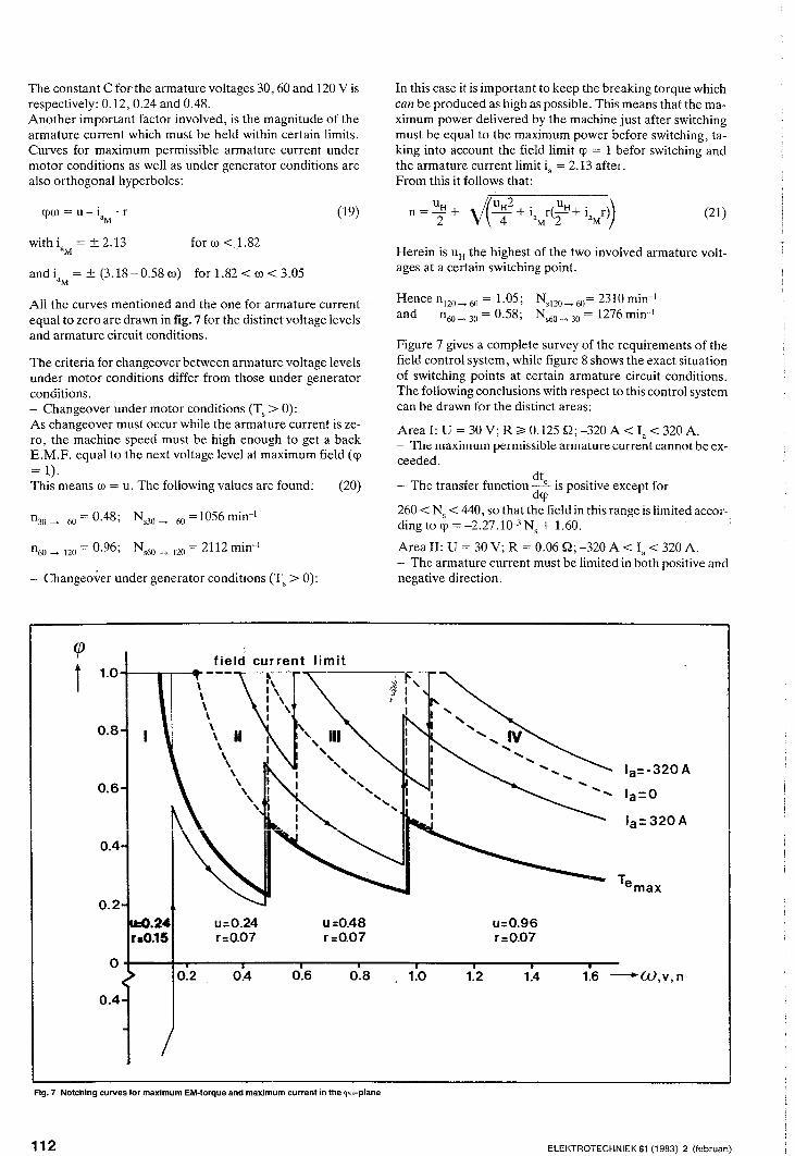
The constant C forthe armature voltages 30, 60 and 120 V is respectively: 0.12, 0.24 and 0.48. Another important factor involved, is the magnitude of the armature current which must be held within certain limits. Curves for maximum permissible armature current under motor conditions as well as under generator conditions are also orthogonal hyperboles:
cpw=u-i 'r aM
with ia = ± 2.13 for w <).82 M
and ia = ± (3.18 - 0.58 w) for 1.82 < w < 3.05 M
(19)
Aii the curves mentioned and the one for armature current equal to zero are drawn in fig. 7 for the distinct voltage levels and armature circuit conditions.
The criteria for changeover between armature voltage levels under motor conditions differ from those under generator conditions. - Changeover under motor conditions (T, > 0): As changeover must occur while the armature current is zero, the machine speed must be high enough to get a back E.M.F. equal to the next voltage level at maximum field (cp = 1). This means w = u. The following values are found: (20)
n30 ---. 60 = 0.48; Ns30 ---. 60 =1056 min-I
n60 ---. 120 = 0.96; Ns60 ---. 120 = 2112 min-I
- Changeover under generator conditions (T, > 0):
Fig.7 Notching curves for maximum EM-torque and maximum current in the «(lw-plane
112
In this case it is important to keep the breaking torque which can be produced as high as possible. This means that the maximum power delivered by the machine just after switching must be equal to the maximum power before switching, taking into account the field limit cp = 1 befor switching and the armature current limit ia = 2.13 after. From this it follows that:
(21)
Herein is uH the highest of the two involved armature voltages at a certain switching point.
Hence n120---.60 = 1.05; and n60 ---. 30 = 0.58;
Nsl20 ---.60= 2310 min-I N,60 ---.30 = 1276 min-I
Figure 7 gives a complete survey of the requirements of the field control system, while figure 8 shows the exact situation of switching points at certain armature circuit conditions. The following conclusions with respect to this control system can be drawn for the distinct areas:
Areal: U = 30V; R ~ 0.125 Q;-320 A < Ia < 320 A. - The maximum permissible armature current cannot be exceeded.
dt - The transfer function _e is positive except for
dcp 260 < Ns < 440, so that the field in this range is limited according to cp = -2.27.10-3 N, + 1.60. .
Area II: U = 30 V; R = 0.06 Q; -320 A < Ia < 320 A. - The armature current must be limited in both positive and negative direction.
ELEKTROTECHNIEK 61 (1983) 2 (februari)

. dt. In the largest part of the area the transfer functIOn ~ IS
dcp negative. During testing it appeared to be satisfactory to
dt consider d; negative all over the area.
Area III: U = 60 V; R = 0.06 Q; -320 A < Ia < 320 A. - The armature current must be limited in both directions.
dt - The transfer function _e is negative all over the area.
dcp
Area IV: U = 120V; R = 0.06Q;-Ia <Ia < Ia ; Ia =f(N); conditions: Identical to area III. M M M
As the exact situation of the curves depend on the battery condition in such a way that under poor battery conditions the curve for maximum torque will possibly become higher situated in the cpw-plane than the maximum motor current curve, it is necessary to take precautions in order to prevent the torque from falling to a very low value. Therefore the field in area II, III and IV is kept above the value of 0.2.
2.3.2. The dynamic behaviour of the separately excited DCmachine with field control In the preceding pages field control has been regarded under ,r quasi-stationary conditions which means that changes occuri so slowly that the system, the electrical as well as the mechanical part, can follow immediately. The system behaviour under these circumstances is the most important for EV-applications, however, with respect to system design also the dynamic behaviour is important [1], [5] and [8].
The transfer function Te or Te can only by determined for cp U f
small signals around a working point due to the non-linearity of machine equations and the load characteristic. The following transfer function can be derived in the Laplace-domain, assuming a linear relationship exists between <I> and <I> a' S
Where: Q() = f V() w
I r 3 c=-QAc~
1 2 F W i'
(22) Rf
s + 1) (Lf()+ s)
A. is a constant necessary to bring into account the rotating parts of the drive. The parameters with subscript "0" refer to the chosen working point. With the well known techniques from control engineering it is possible to determine the response to a step input signal U f_.
ELEKTROTECHNIEK 61 (1983) 2 (februari)
It appears that: - the final value of the response has a sign opposite to that of Uf_(Eo-Ia Ra) (see also fig. 6a.).
o dT - the differential coefficient _e_ at time. = 0 has the same
d. sign as that of the disturbance U f-'
This means that when Eo-Ia Ra>O the system at first shows o
an inverse response (see fig. 9). The transfer function has a zero in the right part of the complex s-plane and is called a nonminimum phase-shift transfer function. The physical explanation for this phenomenon is the existance of the electrical inertia of the armature, through which the transient at the beginning is determined by the field only.
3. REALISATION OF THE CONTROL SYSTEM
In principle an armature current or field control is sufficient to control speed, acceleration and regenerative breaking. However, due to the speed dependence of the field, the accelerator or brake pedal position would need to be readjusted continually in order to keep the desired acceleration or deceleration. By applying an extra torque control loop, the driving or breaking torque is kept constant as far as the armature or field current limits are not exceeded.
In the area where the series resistors are incorporated in the
armature circuit and hence dte > 0, the field is controlled . dcp
straightaway by the accelerator pedal signal. Fig. lOa, and b shows the block diagrams of the distinct control systems.
30V;R=125mH 30V;R=60mu SOV; R::60 m!l 120V;R=60mJl
02\------1 30V;R=740mu 528 1276 2310
440 1056 2112
ov HS open 30V;R=60m!i 6DV;R=60rnfl 120V;R:::::60mJl
'-___ '--____ -'-____ ..J.,
Fig.8 Switching diagram
o 4 8 12 14 16 18 -ems
Fig. 9 Torque resp'onse to step input field winding voltage
113

~------------+--c no
no no
~--------~------·A
r----c no A~-r=1~~----~
no no
yesT--~::::l-__ ~
no
r--------..... --B
no
~--------~------.A
,------.. --B
(.:'" ) c---< B_----L:::::-I
Fig. 14 Flow chart for accelerating and decelerating
114 ELEKTROTECHNIEK 61 (1983) 2 (februari)

3.1. Field current controllers The field current controllers are two-quadrant choppers implemented with power MOSFETs (see fig. 11a). Due to the fact that the excitation voltage can be reversed, current changes can be accomplished with the same speed in both directions (see fig. lIb).
For a fast decrease of the field current, the energy stored in the field windings will be fed back into the battery via the diodes D1 and D2. The frequency of the PWM-signal is 400 Hz which is high enough to get a smooth current at a given field coil time constant of 100 ms. The average excitation voltage and, under stationary conditions, also the average current is proportional to the control voltage applied to the PW-modulator (fig. Hc).
3.2. Measurement of the field Due to the saturation of the magnetic circuit and hence nonlinear relation between If and <l>s' the field current cannot be used straightaway to determine the instantaneous EM-torque. Although, if the hysteresis is neglected, this function can be approximated quite accurately using the method of least squares, in practise it appeared to be satisfactory to make an even coarser approximation with three straight lines which remain all within the hysteresis curve (fig. 12). Based upon this approach the flux value is obtained electro-# nically from the field current. if'
4. FLOW CHART AND BLOCK DIAGRAM OF VOLTAGE ADJUSTING AND FIELD CONTROL SYSTEM
In order to change armature voltage under no-current conditions the current before opening the main switch and the vol-
, ,
+
'2x L ___________ _
I ~I ~llt l I <NUt) CJ
L--------{T
Fig.10a Field control in the area U = 30 V; R;, 125 mQ
la
/
/
+ -
+
30/60/120 V
/ L--+----O L--------------------{T
Fig.10b Torque control in the areas U = 30, 60 and 120 V; R = 60 mQ
+60V
Fig.11a Field current chopper
ELEKTROTECHNIEK 61 (1983) 2 (februari)
o DYN.
1-If
Fig 11b Two quadrant operation
-1
UfAV t 1
o
-1
-1 Uc
Fig. 11 c Excitation voltage vs. control voltage
115

.....
..I.
en
m r m ::j :JJ o --i m () I ~ m A
~ ":::l <D ex> ~
'" CD" g-o: !!l v
"!1 cpO
~ III 15' 0
"" 0. iii'
'" iil 3
I---~~:::I-C::;------ _. --- ---~ 5el.1 5el.2 II r Td ", J,_ --~
I ~~: > I ~ --
psw.D + 51 5f
I
u--+-- I- - - - --- - - - - --- - -- - --- r- -_--------- ____ • ___ I
'---------tt-; 51 ~---------------_H~~Hs
~-~-----------------------,_------L------------------------------~~~HS
I
(I.=<».M I )
0"""""""i/
t":..... N>440
-~ 440-Usw 1
SignTd N
I Dete_c!~i!cuits
Hs
delay
fI'''"'""' L II I"ffi combin.
iii M
& Jk gates
<11
& )11
JUL nl IlUll
~1J -P" M.52,51,Hs
§HS
• 51
52
53
C> S4
S5
S6
57
S8
I I '--.
I
..-J
Contactors
I--60V L----J
I _J
60V It-------'
Illn Main circuit
Battery
4 x 30V

tage across the main switch before closing it in the new state, are forced to zero. Due to this program the field control operates successively under torque-, current-, and voltage control. The entire program is a complex structure which can best be understood by following the flow chart of fig. 14, together with the block diagram of fig. 15. Fig. 13 shows the voltage across the main switch, the armature current and the field current during switching.
5. CONCLUSIONS The conclusions drawn from the obtained test-bench results can be summarized as follows. - It is possible to build a convenient speed control based up-
Q.4
0.2
o Q.2
I (.):::1.43ir!
0.4
, ,
I I
woo{\92.,.o.22! , I
Q.6
Fig. 12 Linear appro.ximatio.n o.f <!>s ~ (If)
LIST OF SYMBOLS AND SUBSCRIPTS
AF Front surface of car. cm Machine constant. Cw Streamline constant. E BackE.M.F. e Normalized E M.F. F, Tractive effort f Friction constant. g Gravity constant. H(s) Complex transferfunction. HS Main switch. Ia Armature current. If Excitation current. ia Normalized armature current.
Mechanical reduction. J Mechanical inertia. La Armature inductance .. Lf Field coil inductance. m Mass of the vehicle. N, Machine shaft speed. p Accelerator position R Total armature circuit resistance Ra Armature resistance. Rf Field coil resistance
RN Nominal armature resistance ~N .
Rp Parking resistor aN
ELEKTROTECHNIEK 61 (1983) 2 (februari)
OB 10 if
I $1'.
on a conventional circuit concept with use of modern control electronics. - The control concept is probably very suitable to implement with microprocessor technology, which means that prices can be acceptable in larger series. - The relatively low torque-armature current ratio, due to the field weakening, can be regarded as a disadvantage of this speed control.
6. ACKNOWLEDGEMENTS The author wishes to express his thanks to professor 1.A. Schot for reading the manuscript and to acknowledge his gratitude to Messrs. Barten, v. d. Boomen and Kremer, who are responsible for much of the realisation of this project.
'~~ ~,---I ~~~
't' 50 ms/div
Fig. 13 Armature current, voltage across main switch and field current vs. time during switching to. a higher vo.ltage
R, Series resistor. r Normalized armature circuit resistance. rw Wheel radius. S Switch s Laplace operator. T, Machine shaft torque
Te Electromagnetic torque. T fr Friction torque.
TL Load torque.
te Normalized EM-torque U Armature voltage Ub Voltage drop across brushes Uf Field coil voltage u Normalized armature voltage. V Vehicle speed. v Normalized vehicle speed a Slope angle .. Ie Constant. v Field winding temperature.
Q Specific air density T Time.
<l>a Enclosed stator flux. <1>, Stator flux.
. <I> CjJ NormalIzed flux <1>"
N (j) Normalized angular speed Q, Angular machine shaft speed
117

Additional subscripts A V Average value. L Laplace domain. M Maximum. m Minimum. N Nominal. o Working point.
Small signals.
REFERENCES
[ 1] Cool, J C., Schijf, F J. Viersma, T. J ,Regeltechniek E!sevier, p..msterdam!8russeI1979
[ 2J Dongen, L A. M. van, 'Aandrijflijnen voor elektrische voertuigen' Rapportnr WV 155-043, T H Eindhoven 1979
· '-'exicht Vexhll1SIoI
Hatenboer-Elektro BV Postbox 200, 2170 AE Sassenheim T elefoon (02522) 19012 * Telex 41205
R
[ 3] Dongen, L, A M, van, Graaf, R van der, 'The Eindhoven Experimental Vehicle' Vehicle Design and Drive Train', Drive Electric Amsterdam 1982
[ 4] Dongen, LAM van, Graaf, R van der, Visscher, W, H, M , 'Theoretical Prediction of Electric Vehicle Energy Consumption and Battery State-of Charge During Arbitrary Driving Cycles', EVC No 8115, EVC Symposium VI Baltimore, Maryland
[ 5] Dar!, R C, Modern Control Systems, third edition Addison-Wesley, Reading Massachusetts 1980
[ 6] Jong, H C, J de, Kreek, J, van der, 'De statische karakteristieken van de gelijkstroomcommutatormachine' Lecture notes EM-3615-0, group Electromechanics, T H Eindhoven
[ 7] Koumans, W A, 'Electric car project of the Eindhoven University of Technology' PPL Conference Publication number 14, pp 87-90
[ 8] Pfaff, G , Reglung Elektrischen Antriebe I' Eigenschaften, Gleichungen und Strukturbilder der Motoren R Oldenbourg Verlag, MOnchen und Wien 1971
[ 9] Siemens, A G , Gleichstrom-Fahrmotor 1 GV1' Technische Beschreibung.
[10] Visscher, W Dongen, LAM van, 'Battery State-of Charge Model for Driving Cycle Operation' Drive Electric Amsterdam 1982
Hitenboer
\


![[3.1] The Changing Landscape of Research Data - Maurits van der Graaf [3TU.Datacentrum Symposium 2014, Eindhoven]](https://static.fdocuments.us/doc/165x107/558375b9d8b42ac8128b48b8/31-the-changing-landscape-of-research-data-maurits-van-der-graaf-3tudatacentrum-symposium-2014-eindhoven.jpg)