TOOLS YOU’LL NEED FOR INSTALLATION GT500 KITinfo.shelbyamerican.com/Instructions/gauge_pod.pdf ·...
10
2005-08 Mustang Gauge Pod installation instructions Page 1 of 10 Figure A Figure B Figure C Thanks for purchasing the Center Gauge Cluster with Shelby Gauges, from Shelby Performance Parts. Start by opening your kit and checking the contents to make sure everything is complete before getting started. GT500 KIT (Figure A) • Wire harness and terminal kit • Billet fuel block w/ brass plug and two 5/32” Allen head bolts and washers • Vacuum “T” Fitting • Oil block w/ three installed plugs, one installed adapter and one loose adapter • Stainless braided line • Two Adel clamps SHELBY / GT NON-SUPERCHARGED (Figure B) • Wire harness and terminal kit • Billet fuel block w/ brass plug and two 5/32” Allen head bolts and washers • Oil block and mounting bracket w/ three installed plugs and three installed adapters • Stainless braided line • Two 17mm bolts and lock washers for mounting bracket SHELBY / GT SUPERCHARGED (Figure C) • Wire harness and terminal kit • Billet fuel block w/ brass plug and two 5/32” Allen head bolts and washers • Vacuum “T” Fitting • Oil block and mounting bracket w/ four installed plugs and three installed adapters • Stainless braided line • Two 17mm bolts and lock washers for mounting bracket TOOLS YOU’LL NEED FOR INSTALLATION • Teflon tape or liquid Teflon • Two dozen zip ties • Electrical tape • Four 1” x 1” squares of Velcro • Heat shrink wrap (optional) • Soldering gun and solder (optional) • Rigid 10gauge wire or welding wire • Wire cutters, crimpers and strippers • 3/8” and 1/4” ratchet • 8mm socket 1/4” drive • 13mm and 17mm deep sockets 3/8” drive • 3/8”,9/16”,7/8”,13/16” and 12mm wrench • 5/32” Allen key • Four jack stands • Floor jack • Safety glasses and gloves A few notes about installation - Although we’ve made every effort to make these instructions as complete as pos- sible for the average do-it-yourself enthusiast, we highly recommend having this installation performed by a certified mechanic at a professional automotive facility. This installation requires a certain intimate mechanical and electrical understanding of automotive systems. The installation of this system may or may not interfere with your factory war- ranty, so you should consult with your local dealer prior to installation. During the installation of the system, extra care should always be given to routing wires away from moving parts and excessive heat that would cause undesirable function or failure. Also, be sure to follow the directions thoroughly (and in order) to prevent the need to re-do any processes. Also, study the wiring schematic for your application to help further your familiarity with where the wires are going prior to starting. On supercharged applications, the nylon tube for the boost gauge needs to always be handled with care when routing, as any kinks in the line will cause leaks and the gauge to not function properly. When tightening any of the brass fitting on a fluid connection, it is not necessary to tighten the fitting as much as possible. Generally, the fittings are tapered and need only to be tightened down securely with a good amount of resistance. Over-tightening will actually promote a leak. Since you are working with the vehicle’s electrical system, be sure to disconnect the battery before getting started. It would also be to your benefit to make sure the car has not been run for about twelve hours and is cooled down. Following directions properly, this installation should take about three hours and will require the help of a friend for about ten minutes at one point during the installation.
-
Upload
duongquynh -
Category
Documents
-
view
215 -
download
0
Transcript of TOOLS YOU’LL NEED FOR INSTALLATION GT500 KITinfo.shelbyamerican.com/Instructions/gauge_pod.pdf ·...

2005-08 Mustang Gauge Pod installation instructionsPage 1 of 10
Figure A
Figure B
Figure C
Thanks for purchasing the Center Gauge Cluster with Shelby Gauges, from Shelby Performance Parts. Start by opening your kit and checking the contents to make sure everything is complete before getting started.
GT500 KIT (Figure A)• Wire harness and terminal kit• Billet fuel block w/ brass plug and two 5/32” Allen head bolts and washers• Vacuum “T” Fitting• Oil block w/ three installed plugs, one installed adapter and one loose adapter• Stainless braided line• Two Adel clamps
SHELBY / GT NON-SUPERCHARGED (Figure B)• Wire harness and terminal kit• Billet fuel block w/ brass plug and two 5/32” Allen head bolts and washers• Oil block and mounting bracket w/ three installed plugs and three installed adapters• Stainless braided line• Two 17mm bolts and lock washers for mounting bracket
SHELBY / GT SUPERCHARGED (Figure C)• Wire harness and terminal kit• Billet fuel block w/ brass plug and two 5/32” Allen head bolts and washers• Vacuum “T” Fitting• Oil block and mounting bracket w/ four installed plugs and three installed adapters• Stainless braided line• Two 17mm bolts and lock washers for mounting bracket
TOOLS YOU’LL NEED FOR INSTALLATION
• Tefl on tape or liquid Tefl on• Two dozen zip ties• Electrical tape• Four 1” x 1” squares of Velcro• Heat shrink wrap (optional)• Soldering gun and solder (optional)• Rigid 10gauge wire or welding wire• Wire cutters, crimpers and strippers• 3/8” and 1/4” ratchet• 8mm socket 1/4” drive• 13mm and 17mm deep sockets 3/8” drive• 3/8”,9/16”,7/8”,13/16” and 12mm wrench• 5/32” Allen key• Four jack stands• Floor jack• Safety glasses and gloves
A few notes about installation - Although we’ve made every effort to make these instructions as complete as pos-sible for the average do-it-yourself enthusiast, we highly recommend having this installation performed by a certifi ed mechanic at a professional automotive facility. This installation requires a certain intimate mechanical and electrical understanding of automotive systems. The installation of this system may or may not interfere with your factory war-ranty, so you should consult with your local dealer prior to installation. During the installation of the system, extra care should always be given to routing wires away from moving parts and excessive heat that would cause undesirable function or failure. Also, be sure to follow the directions thoroughly (and in order) to prevent the need to re-do any processes. Also, study the wiring schematic for your application to help further your familiarity with where the wires are going prior to starting. On supercharged applications, the nylon tube for the boost gauge needs to always be handled with care when routing, as any kinks in the line will cause leaks and the gauge to not function properly. When tightening any of the brass fi tting on a fl uid connection, it is not necessary to tighten the fi tting as much as possible. Generally, the fi ttings are tapered and need only to be tightened down securely with a good amount of resistance. Over-tightening will actually promote a leak. Since you are working with the vehicle’s electrical system, be sure to disconnect the battery before getting started. It would also be to your benefi t to make sure the car has not been run for about twelve hours and is cooled down. Following directions properly, this installation should take about three hours and will require the help of a friend for about ten minutes at one point during the installation.

2005-08 Mustang Gauge Pod installation instructionsPage 2 of 10
NON-SUPERCHARGED GAUGE POD CLUSTER SUPERCHARGED GAUGE POD CLUSTER
FUEL PRESSUREOIL PRESSURE OIL TEMPERATURE
Power (white)to vehicle headlight switch
from supplied harness
Gauge Illumination
Ground (black)to trans tunnel boltfrom supplied harness
Ground (black)to trans tunnel bolt
from supplied harness
Power (Red)to vehicle harness(under dash) fromsupplied harness
Signal (Blue)to sender fromsupplied harness
Signal (Brown)to sender fromsupplied harness
Signal (Black/purple/grey)to sender fromsupplied harness
FUEL PRESSURE OIL PRESSURE BOOST PRESSURE
Power (white)to vehicle headlight switch
from supplied harness
Gauge Illumination
Ground (black)to trans tunnel boltfrom supplied harness
Ground (black)to trans tunnel bolt
from supplied harness
Power (Red)to vehicle harness(under dash) fromsupplied harness
Signal (Nylon tubing)to vacuum “T” fi t-ting from gauge
Signal (Brown)to sender fromsupplied harness
Signal (Black/purple/grey)to sender fromsupplied harness
2005-08 Mustang Gauge Pod installation instructionsPage 3 of 10
Start by installing the gauges into the pod as shown (Fig-ure 1 or Figure 2). Next you’ll want to wire the illumination circuit for the gauge lights (Figure 3). Crimp all three white wires together (Figure 4) and then all black wires together with the supplied male barrel connectors (Figure 5). Next wire the power and ground circuits to the fuel pressure gauge by connecting the red and black independent wires from the fuel gauge harness (NOT the black one already terminated to the sender harness) (Figure 6) to the pre-stripped red and black wires on the supplied harness (Fig-ure 7).
Figure 1 Figure 2
Figure 3 Figure 4
Figure 6 Figure 7Figure 5
2005-08 Mustang Gauge Pod installation instructionsPage 4 of 10
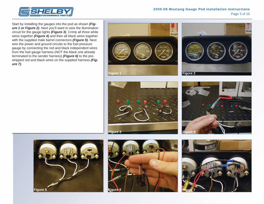
Next carefully cut the wiring harness that connects the fuel pressure gauge to the sender that is included with the gauge. Cut it approximately 36” from the gauge and the wires will be a matching thickness in Purple/Black/Grey (Figure 8). This is necessary to complete the next step of the installation which will be fi shing the wires through the dash. Before you can do that, though, refer back to the wiring schematic and ensure that all connections to the gauges themselves is complete. Once you fi sh the wiring through the dash, you simply won’t have the slack or the room to work behind the gauges so this is very important. First, locate the hole that is under the dash on the driver side (Figure 9). You’ll want to push through a “pull line” from under the dash to exit out the top of the dash at the base of the windshield. You can use a piece of 24” rigid electrical or welding wire. In this case, I used the nylon boost tube for reference only and just to illustrate location of the “pull line” itself (Figure 10). Before fi shing the lines through the dash, you’ll need to tape all the loose ends on the harness in an effort to make everything one, continuous line that will not snag when going through the dash (Figure 11 and 12). Tape the furthest end of the supplied harness wire [this will either be the brown wire (supercharged) or the brown and blue wire (non-supercharged)] to your “pull line” and care-fully pull through the dash. (Figure 13 and 14).
Figure 8 Figure 9
Figure 10 Figure 11
Figure 13 Figure 14Figure 12

2005-08 Mustang Gauge Pod installation instructionsPage 5 of 10
Next bring the wiring down (Figure 15) and secure with zip ties. You’ll want the white and the brown (or brown and blue) wires to route under the steering column as shown (Figure 16) and the Purple/Black/Grey fuel pressure wires over the column. The thicker gauge red and black wires should be hanging down by where the white wire makes a 90° turn under the steering column.
Now its time to carefully remove the headlight switch as-sembly and bring your white illumination wire out the hole from inside the dash (Figure 17). The white wire from the supplied harness is to be connected to the black wire with the white tracer (stripe) as shown (Figure 18) . [You will be using the supplied connections for this. The purple clam-shell shuts over and pierces the black wire with the white tracer (stripe) and then the red male spade fi tting is crimped over the white wire from the supplied harness. The two are then joined together. Re-install the headlight switch and make sure all connections are secure and all related wiring is fastened with zip ties.
Going back again to the area where the wiring and tube make a 90° turn to route under the column (where the red and black wires are still hanging), locate and unwrap about a 6” length of the vehicle’s main electrical harness. In the bundle of wires will be a white wire with a yellow tracer (stripe) that you’ll want to isolate with enough room to con-nect the red wire that is hanging down from the supplied harness. It will be done in exactly the same fashion as the wire that was connected to the headlight switch with the supplied connectors (Figure 19). Secure all connections, re-wrap the vehicles main harness and fasten the related wiring with zip ties.
In that same area you will see a metal plate with two 13mm bolts where the center console meets the transmission tun-nel on the driver side. Using the supplied large ring connec-tor, securely crimp or solder it to the end of the main (thick-er) black wire from the supplied harness that you pulled through the dash (that is already hanging there). Remove the 13mm bolt closest to the gas pedal and re-install with the ground wire and ring terminal sandwiched as shown (Figure 20).
Figure 15 Figure 16
Figure 17 Figure 18
Figure 19 Figure 20
2005-08 Mustang Gauge Pod installation instructionsPage 6 of 10
Figure 5 Figure 6
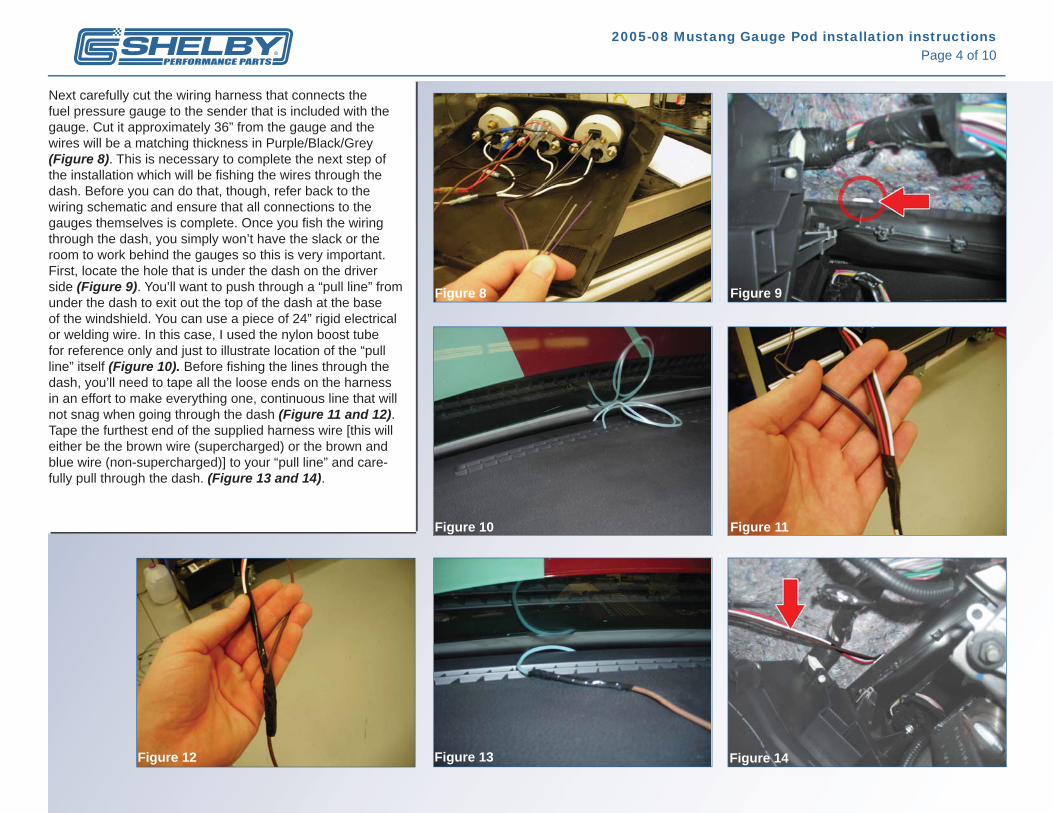
Now you’ll want to fi nd the other end of your fuel pressure sender’s harness that you cut previously in this installation. It will now become your “pull line” through the vehicle fi rewall. Tape the exposed/cut ends together and drop them down into the wire harness hole as shown (Figure 21). This hole is located closest to the corner of where the edge of the hood meets the fi rewall on the driver side in the engine compartment. This particular part of the process requires two people. Have one person hold onto the line you dropped down into the hole. Have another go into the car under the dash, in the same area, and remove (it just pulls out) the main vehicle wiring harness rubber boot. When you pull it out, you will see the wires that were just dropped down. Grab them and pull them through as far as you can, having your partner feed you the wire as much as they can without actually letting it go (Figure 22). To route the wire properly, you’re going to cut the rubber “nipple” that is molded into the back of the rubber vehicle wire harness boot and then fi sh your three lines through the hole that it creates (Figure 23). You can now re-install the boot and it should look like the picture shown (Figure 24). With your partner still holding the last little bit of wire in the engine compartment side, you’ll want to tape the nylon tubing and brown wire (supercharged applications) or brown and blue wire (non-supercharged applications) as close to the rubber boot and as high up as possible on the Purple/Black and Grey wires you just pulled through (Figure 25).
NOTE: You want to be sure at this point that the wire path under the dash to the rubber boot does not interfere with the steering linkage or the clutch pedal (if it applies) move-ment in any way. Make sure the path is around these two pieces before proceeding!
At this point your partner can slowly pull all the wire towards them. Your taped on wires should come through into the engine compartment without issue. When you see your wires coming through the hole (as shown) you want to stop (Figure 26). Un-wrap everything you just taped together in this step. Have your partner continue to pull the wiring through (except the Purple/Black/Grey ones) until the wire is taut. The goal is to not pull all of the Purple/Black/Grey wires out from inside the vehicle at the rubber boot. You need these to connect back to the Purple/Black/Grey wires currently hanging over the steering column where you previously left them. At this point you can connect them back together with the three supplied blue butt connectors. Purple to purple, black to black and grey to grey. Be sure one last time that all wires under the dash are secured and out of the way. You are now fi nished inside the vehicle.
Figure 21 Figure 22
Figure 23 Figure 24
Figure 25 Figure 26

2005-08 Mustang Gauge Pod installation instructionsPage 7 of 10
Figure 5 Figure 6
The next step will be to assemble the fuel block assembly as shown (Figure 27). The brass fuel plug goes on the short side of the block and the fuel pressure sender goes into the longer side of the block with a 7/8” wrench. We recommend you place the assembly carefully in a vise while snugly tightening the fi ttings. You do not want to use any type of sealant or Tefl on on the fuel block assembly. The brass plug and the sender are tapered to ensure a leak free instal-lation. Using Tefl on or sealant may contaminate the fuel system and clog the injectors causing damage or failure to the engine. On both the GT500 and the GT, remove the two 8mm bolts from the factory fuel sender and disconnect the factory electrical harness. Re-install the factory fuel sender on your billet assembly as shown and install back onto the fuel rail with supplied 5/32” Allen bolts and washers. Recon-nect electrical harness (Figure 28 and 29).
Fish the wiring in the engine compartment out the hole and over the master cylinder, in front of the vacuum booster. On the GT, the wiring/tube will follow along parallel to the driver side fuel rail (Figure 30). On the GT500, only the oil pres-sure (brown wire) will follow along that same path.
The next part is specifi c to supercharged GTs but procedur-ally will be the same for GT500. You want to use the wire cutters to cleanly cut the factory rubber vacuum tube im-mediately over the last fuel injector closest to the fi rewall on the driver side (injector is blue in photo; GT only) as shown (Figure 31). Using the supplied vacuum “T” fi tting, connect each side of the cut tube over the fi tting and then connect the nylon tube into the fi tting, sliding the special rubber boot (supplied in gauge box) over the tube and then over the fi t-ting. We also recommend a tight wrap of electrical tape or a ½” piece of heat shrink tube where the nylon tube meets the special boot. This will prevent leaks and blow-outs where the force of the air pressure under boost could blow the line off the vacuum fi tting (Figure 32).
Figure 27 Figure 28
Figure 29 Figure 30
Figure 31 Figure 32

2005-08 Mustang Gauge Pod installation instructionsPage 8 of 10
For GT500 owners the procedure is basically the same except you’re routing your fuel pressure wiring and nylon tubing around to the passenger side fuel rail as shown (Figure 33). You are also making your cut at the factory fuel pressure sending unit where the tube meets the sender (Figure 33). GT500 owners may also need a 1.5” piece of ¼” ID rubber vacuum tube to adapt the vacuum signal line off the factory fuel pressure sending unit (sitting on top of your billet assem-bly) to the vacuum “T” fi tting we supply (Figure 33 and 34). In the case of both the GT and GT500, the brown wire (and the blue for the non-supercharged vehicles) needs to be rout-ed safely around the front of the passenger-side valve cover and then straight down to the bottom of the car as shown (Fig-ure 35), where it can hang loosely for the next step. Particu-lar care has to be used to ensure that the wires will not be too close to the exhaust manifold or steering linkage. NOTE: The next part of this installation requires work-ing under the vehicle itself. If you do not have a lift, make sure that the vehicle is securely supported at all four corners with jack stands and you have a fl oor jack near you supporting the vehicle as a safety precaution. Wear your safety glasses at all times. Even though it may not be titled as your vehicle application, it is helpful to read the directions for all applications since many of the steps pertain to every application. Refer to the pictures to verify all assemblies are done correctly prior to installation.Next remove the factory oil pressure sending unit from the vehicles oil fi lter plate on the engine itself with the 13/16” wrench. This is located directly above the oil fi lter on GTs and GT500s. Since the piece is above the oil level, you will only have a few drips of oil to clean up, it will not come fl owing out. Once removed, you will need to assemble your oil block as needed for your particular vehicle’s application.
Figure 33
Figure 34
Figure 35
2005-08 Mustang Gauge Pod installation instructionsPage 9 of 10
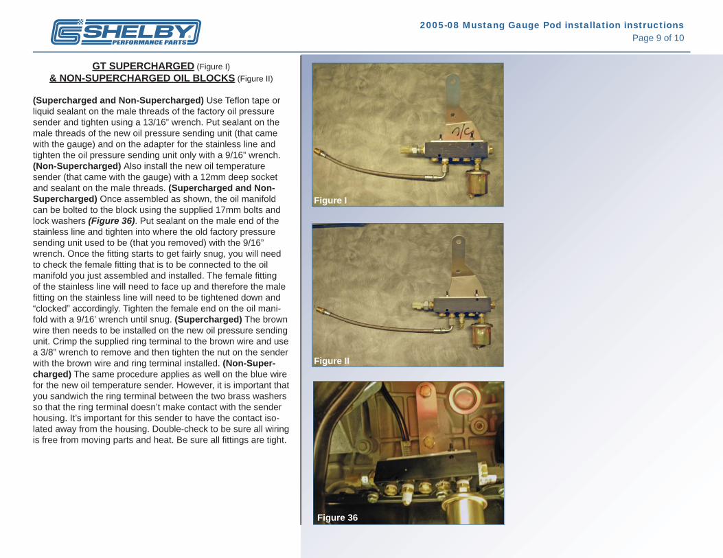
GT SUPERCHARGED (Figure I) & NON-SUPERCHARGED OIL BLOCKS (Figure II)
(Supercharged and Non-Supercharged) Use Tefl on tape or liquid sealant on the male threads of the factory oil pressure sender and tighten using a 13/16” wrench. Put sealant on the male threads of the new oil pressure sending unit (that came with the gauge) and on the adapter for the stainless line and tighten the oil pressure sending unit only with a 9/16” wrench. (Non-Supercharged) Also install the new oil temperature sender (that came with the gauge) with a 12mm deep socket and sealant on the male threads. (Supercharged and Non-Supercharged) Once assembled as shown, the oil manifold can be bolted to the block using the supplied 17mm bolts and lock washers (Figure 36). Put sealant on the male end of the stainless line and tighten into where the old factory pressure sending unit used to be (that you removed) with the 9/16” wrench. Once the fi tting starts to get fairly snug, you will need to check the female fi tting that is to be connected to the oil manifold you just assembled and installed. The female fi tting of the stainless line will need to face up and therefore the male fi tting on the stainless line will need to be tightened down and “clocked” accordingly. Tighten the female end on the oil mani-fold with a 9/16’ wrench until snug. (Supercharged) The brown wire then needs to be installed on the new oil pressure sending unit. Crimp the supplied ring terminal to the brown wire and use a 3/8” wrench to remove and then tighten the nut on the sender with the brown wire and ring terminal installed. (Non-Super-charged) The same procedure applies as well on the blue wire for the new oil temperature sender. However, it is important that you sandwich the ring terminal between the two brass washers so that the ring terminal doesn’t make contact with the sender housing. It’s important for this sender to have the contact iso-lated away from the housing. Double-check to be sure all wiring is free from moving parts and heat. Be sure all fi ttings are tight.
Figure I
Figure II
Figure 36

2005-08 Mustang Gauge Pod installation instructionsPage 10 of 10
GT500 SUPERCHARGED OIL BLOCK (Figure III)
The sender and sealant procedure for the oil manifold and stainless line are the same at the GT application except the oil manifold is mounted differently on the vehicle and the stainless line is installed in the opposite direction. Us-ing the two supplied adel clamps, you will need to sus-pend the oil manifold from the power steering line closest to the sway bay, directly behind it. This is accomplished by removing the two bolts in the oil manifold block using a 5/32” Allen key and 3/8” wrench. Place the adel clamps over the power steering line and then re-install the bolts into the oil manifold as shown (Figure 37). Put sealant on the male end of the stainless line and install into the oil manifold with a 9/16’ wrench. You’ll need to stop as soon as the fi tting gets fairly snug. The female fi tting needs to face down on the stainless line and therefore the male end of the stainless line needs to be tightened down and “clocked” accordingly Note: This is the opposite direc-tion of the stainless line on the GT’s. Place sealant on both male ends of the supplied brass adapter and snug the larger male end into the oil fi lter plate, where the fac-tory oil pressure sender used to be (that you removed), with a 9/16” wrench. Now tighten the stainless line onto the adapter with a 9/16” wrench. Everything should look as shown (Figure 38, 39 and 40). The brown wire then needs to be installed on the new oil pressure sending unit. Crimp the supplied ring terminal to the brown wire and use a 3/8” wrench to remove and then tighten the nut on the sender with the brown wire and ring terminal installed.
Reconnect the battery and start the car, checking for any fuel or oil leaks. At this point, you will want to place the Velcro squares onto the gauge pod and secure it to the top of the dash prior to your test drive. On the non-super-charged cars, it may take a little time after you start the vehicle for the oil temperature to show which is normal. Enjoy your new gauge cluster from Shelby Performance Parts!
Figure 38
Figure 40
Figure 37
Figure 39
Figure III