Tipping Calculations - adventuresofgreg.blog
16
Theoretical Tipping calculations of the TCR1 © COPYRIGHT BEN.P.EADIE 2004 Part 1. Straight and level This study is also based on the rider position being exactly as it is in the diagrams, any shifting and or weight change can dramatically alter the calculations. These are only to serve as a basis of design and re-design and to further our knowledge of the dynamics of this vehicle. First we are going to determine the stability concepts on a straight and level run… Figures One and Two will be the basis of the calculations. Problem: To determine the force on the front wheel and the rear two wheels. To do this we will sum the moments about the point of contact of the rear wheels from the side view. = m L M a * This is the Sum of the forces about A is length times mass Figure 1 (Side view of straight and level) a
Transcript of Tipping Calculations - adventuresofgreg.blog

Theoretical Tipping calculations of the TCR1
© COPYRIGHT BEN.P.EADIE 2004
���������������� ����������������������������� ����������������������������� ����������������������������� �����������������
Part 1. Straight and level This study is also based on the rider position being exactly as it is in the diagrams, any shifting and or weight change can dramatically alter the calculations. These are only to serve as a basis of design and re-design and to further our knowledge of the dynamics of this vehicle. First we are going to determine the stability concepts on a straight and level run… Figures One and Two will be the basis of the calculations.
Problem: To determine the force on the front wheel and the rear two wheels. To do this we will sum the moments about the point of contact of the rear wheels from the side view.
� = mLM a *
This is the Sum of the forces about A is length times mass
Figure 1 (Side view of straight and level)
a
Theoretical Tipping calculations of the TCR1
© COPYRIGHT BEN.P.EADIE 2004
Given: Mass = 155lbs for Greg + 30lbs for the Trike = 185lbs Diagram above for the distances or lengths required
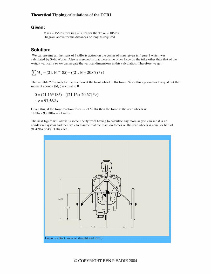
Solution: We can assume all the mass of 185lbs is action on the center of mass given in figure 1 which was calculated by SolidWorks. Also is assumed is that there is no other force on the trike other than that of the weight vertically so we can negate the vertical dimensions in this calculation. Therefore we get:
� +−= )*)67.2016.21(()185*16.21( rM a
The variable “r” stands for the reaction at the front wheel in lbs force. Since this system has to equal out the moment about a (Ma ) is equal to 0.
lbsr
r
58.93)*)67.2016.21(()185*16.21(0
=∴+−=
Given this, if the front reaction force is 93.58 lbs then the force at the rear wheels is: 185lbs - 93.58lbs = 91.42lbs. The next figure will allow us some liberty from having to calculate any more as you can see it is an equilateral system and then we can assume that the reaction forces on the rear wheels is equal or half of 91.42lbs or 45.71 lbs each
Figure 2 (Back view of straight and level)

Theoretical Tipping calculations of the TCR1
© COPYRIGHT BEN.P.EADIE 2004
Conclusion: In summation we have the reaction forces as follows:
1. Front wheel is 93.58lbs 2. Rear right wheel is 45.71 3. Rear left wheel is 45.71
Given an average friction coefficient of 0.85 for rubber on pavement this means in a straight and level run the vehicle can resist 185lbs*0.85 = 157.25lbs side force. Keep in mind that the location of the center of the force will determine a slide vs. tip. Generally if the force center is above the average center of the front and rear axels at the midpoint between the front and rear contact points it will cause a tipping action. If however the force is below this location and above the 157.25lbs then a slide will be induced. This could be wind acting on a faring placed over the vehicle.
Observations: One issue observed from figure 2 is that the cross bar of the rear axel assembly it is above the enter of mass, this means that there is a moment from the center of mass directly to the rear tire point of contact. This will induce a horizontal force on the frame causing the frame to flex out in reaction; although this force may be slight it may affect rolling resistance. This force could possibly be countered if the cross bar was lower than the center of mass, at the axel height or a truss system added. This also brings up one fact that if a trike could be designed so that the center of mass was below the axels the vehicle would have orders of magnitude greater resistance to tipping. Further information on trike tipping can be found at http://www.rqriley.com/3-wheel.html From figure 3 lets analyze the moment about the left wheel due to the forces. Some assumptions can be made A is the reaction force of the wheel. C is the total reaction force due to the moment about the CofG. Due to the angle being close to 45 degrees 45.112 to be exact it will be assumed that the force at B is equal to the force A. This means that there is a force of 45.71lbs acting outwards on each wheel. This may cause a slight flex in the frame between the crossbar and the axel. This could be negated by having a cross bar at the axel height or by adding a truss system like the one shown in figure 4.
Figure 3

Theoretical Tipping calculations of the TCR1
© COPYRIGHT BEN.P.EADIE 2004
Because of this system there also may be an added slight camber to the rear wheels that could be considered a positive for the next study in part 2 that includes a G force side load…
Figure 4

Theoretical Tipping calculations of the TCR1
© COPYRIGHT BEN.P.EADIE 2004
Part 2 Turn loading study This study will determine the loading of a turning maneuver on the vehicle. Using the concepts and formula from the previous study in Part 1 the loading on the wheels during a turn will be found. In this, the calculations should show a tipping, sliding or neutral system induced movement and lead us into how to counteract them. A few assumptions will be made:
1. The maximum side load on a average car is approximately 0.8 as determined by the information on this site http://hypertextbook.com/physics/mechanics/acceleration/ due to constraints we will determine the max G force by the max bank angle of the trike for this calculation.
2. The coefficient of friction on the tires will be around 0.8 as found on this website. http://www.roymech.co.uk/Useful_Tables/Tribology/co_of_frict.htm also the theory behind the friction coefficient and why surface contact patch is not taken into account on calculations. http://www.physlink.com/Education/AskExperts/ae140.cfm
3. No outside influence on the vehicle such as wind will be taken into account.
Problem: To determine whether under a full-banked turn with a G force to be calculated by the bank angle will the vehicle tip or slide?
Given: 1. The dimensional information on the following diagrams 2. Weight to be 185lbs including vehicle 3. Along the horizontal plane a G force of 0.4 will be used
determined by the bank angle of 22 degrees as in figure 4. 4. A friction coefficient of 0.8 5. Having an acceleration of 0.4 G and being able to calculate the
radius of the turn given the bank angle we can determine the velocity required to acquire the G force using a simple formula. Normal acceleration (G force) is equal to the velocity squared over the radius of the turn.
rv
n
2
=α
nrv α*2 =∴
Note: G force and the Coefficient of friction are unitless multiples of the total weight. This said one can be compared directly to the other in other words if the coefficient of friction for rubber on pavement is 0.8 then there is a max G force load of 0.8 before a skid is induced so there is no need to calculate past 0.8 G’s To determine the radius see the following illustration figure 6
Figure 5

Theoretical Tipping calculations of the TCR1
© COPYRIGHT BEN.P.EADIE 2004
First observation from this figure is that there are two differing measurements for the radius between the center of the rear axel this means that the rear wheels are not coordinated in the turn and will provide added rolling resistance how much added will have to be determined at a later date. For this calculation we will take an average of these two radii or 179.175. Acceleration due to gravity is 32.2 ft/sec2 or 386.4in/sec2 therefore 0.4 times the acceleration equals 154.564in/sec2
nrv α*2 =∴
2sec/564.154*175.179 ininv = v = 166.415 in/sec v = 13.87ft/sec v = 9mi/hr or 15kmh This may seem to be a very slow velocity but given the small radius of the turn being only 14 feet, as seen in figure 6, this seems adequate. This is also the force required to have the front wheel in balance with the accumulated forces, this is not to say it cannot handle a greater G load without tipping it is merely the optimal velocity and radius turning configuration for a bank of 22 degrees. It will be necessary to accumulate some empirical data on high speed turns such as a comfortable turning radius at high speed and or to estimate this data and then run through another set of calculations given this data.
Solution: Given the dimensional information on figure 6, and using the calculation formula used in the first part of section one. The reaction forces on the front and aft sections of the vehicle will be calculated. G force loading will not be taken into account in this plane of calculations. It will also be assumed that the bank of the front wheel will be enough to negate the effect of the G force loading as commented in this website http://www.rqriley.com/3-wheel.html. The side loading will only affect the rear axel section and will only be calculated for this. Using
� = mLM a *
Figure 6

Theoretical Tipping calculations of the TCR1
© COPYRIGHT BEN.P.EADIE 2004
� +−= )*)5.2196.20(()185*96.20( rM a
lbsr
r
32.91)*)5.2196.20(()185*96.20(0
=∴+−=
Given this, if the front reaction force is 91.32 lbs then the force at the rear wheels is: 185lbs – 91.32lbs = 93.68lbs. The determination of the loads on the rear wheels now needs to have the side G force element added
Figure 6
a

Theoretical Tipping calculations of the TCR1
© COPYRIGHT BEN.P.EADIE 2004
Given a G force of 0.404 which is equal to 74.74lbs
� +−= )*)96.2051.21(()74.74*51.21( rM a
lbsr
r
85.37)*)96.2051.21(()74.74*51.21(0
=∴+−=
Now that the reaction force on the aft section of the trike is determined the reaction force of the front wheel needs to be the remainder of the force or 74.74lbs-37.85lbs or 36.89lbs Now given the horizontal reaction force on the aft section of the trike due to turning we can calculate the total forces and moments to determine if the vehicle will tip, slide or stay in equilibrium.
Figure 7
a

Theoretical Tipping calculations of the TCR1
© COPYRIGHT BEN.P.EADIE 2004
Next, sum up all the forces into a moment about a. Positive directions will be to the right and down and negative will be up and to the left, if the solution comes out negative the vehicle will not be in a tipping effect. Then if not in a tipping effect side force and friction will be calculated based on the total forces on the system.
� = mLM a *
)*)09.1531.18(()26.16*85.37()32.91*31.18(0 b++−=
b
b
bb
=−=−
+=+−=
36.31*4.3363.1056
)*4.33(07.1672441.615)*4.33()441.615()07.1672(0
Because the negative value can cause some confusion the next diagram figure 9 will clarify the calculation.
Figure 8

Theoretical Tipping calculations of the TCR1
© COPYRIGHT BEN.P.EADIE 2004
Therefore in this configuration the vehicle will not tip due to the forces on it. Given the large number it would be assumed that this a stable maneuver. More calculations on turning will be put on hold until further empirical data is acquired on turning. The next calculations will determine if on this maneuver the vehicle will skid. It can be determined what the necessary G load is required to tip the trike but establishing weather or not the vehicle skids first before the tip is induced is necessary as a skid will negate most of the energy required to tip. That being said considerations that as the side load increases the weight on the inside tire decreases and the weight on the outside tire increases, this will affect the skid calculation, how it affects the system is yet to be determined but can be derived from these sample calculations. This is not to say the vehicle will not tip in a skid, there are many other factors to consider such as imperfections in the ground surface and a change in friction coefficient due to a change in ground conditions or ground type. Next to determine if the vehicle will slide or skid sideways due to the forces it will be necessary to determine the force on the left wheel. Because this is not an equilateral single dimension system we will need to do a similar calculation of a moment about b
Figure 9

Theoretical Tipping calculations of the TCR1
© COPYRIGHT BEN.P.EADIE 2004
� = mLM b *
)*)09.1531.18(()26.16*85.37()32.91*09.15(0 a+−+=
You will note that we are this time adding the moment due to the G force because in this system it is considered a positive. In this scenario down and to the left is positive and up and to the right is negative.
a*4.33441.61513780 ++=
a*4.3346.1993 =−
a=− 68.59 Now that we have a force of 59.68lbs on the outside or left rear wheel, a force of 31.36 on the inside or right wheel and finally a force of 91.32lbs on the front wheel, we can determine if the aft of the vehicle will skid or slide. For the front wheel there is a G loading of 36.89lbs, and a downward force of 91.32lbs. If we take the downwards force and multiply it by the friction coefficient of 0.8 we get a value of 91.32*0.8=73.06lbs This is more than adequate to resist the g loading of 36.89lbs by a factor of nearly 2 so the front section of the trike is not going to tip or skid in this scenario.
Figure 9

Theoretical Tipping calculations of the TCR1
© COPYRIGHT BEN.P.EADIE 2004
It was shown in previous calculations that the vehicle will not tip under these loading conditions on the aft section of the trike. Now given a loading of 59.68lbs + 31.36lbs on the section and multiplying by the friction coefficient we get (59.68+31.36)*0.8=72.83lbs there is again a more than adequate reaction force to the G force of 37.38lbs on the aft section to counter a skid by a factor nearing 2.
Figure 10

Theoretical Tipping calculations of the TCR1
© COPYRIGHT BEN.P.EADIE 2004
Conclusion: With this calculation we have determined that the vehicle is quite stable in a 0.4 g turn at a radius of approximately 14 feet, the safety factor in this movement is approximately 2 implying that a turn in a similar bank and radius could (in estimation) approach 0.6 before a tip or a slide is induced. 0.6 was chosen instead of the logical 0.8 or double 0.4 due to the safety factor, as this calculation was at a maximum bank angle of 22 degrees, as the bank then cannot increase with G loading it will be necessary to apply calculations such as done of the aft section to it on any loading past 0.4 G. This will in turn reduce the reaction to the G load and then decrease the stability.
Observations: Increasing the bank angle may be a consideration in making the trike more stable increasing the bank to 30 degrees will allow the trike to maneuver a tighter radius turn at a force loading of 0.55 G. this however does not take into account the skidding that may be induced due to the load. This study is also based on the rider position being exactly as it is in the diagrams, any shifting and or weight change can dramatically alter the calculations. These are only to serve as a basis of design and re-design and to further our knowledge of the dynamics of this vehicle. Further study on the affects of camber of a rear wheel on stability will be analyzed in the future part three of this study. Below is another easier calculation on the tipping vs. skid by Robert Q Riley and is a good check for my calculations above.

Theoretical Tipping calculations of the TCR1
© COPYRIGHT BEN.P.EADIE 2004
Max G Force Descriptive geometry from Robert Q Riley report Using diagram below it was mimicked on the trike. Although with the front leaning section it will absorb more force than the rear, this calculation will predict the maximum G load in a banked turn that the rear section can handle before tipping. If this value is lower than the skid value of the bank the vehicle will tip at this load, if not it will skid Using the diagram here taken from http://www.rqriley.com/images/fig-3whl.gif this is a part of the article here http://www.rqriley.com/3-wheel.html which is a good read for those interested in more in depth reasoning on the design of trikes, powered by humans or motors.
We will re establish the geometry as per the trike.

Theoretical Tipping calculations of the TCR1
© COPYRIGHT BEN.P.EADIE 2004
Removing the Manikin you can see the cone generated by the Half Track. In the next diagram

Theoretical Tipping calculations of the TCR1
© COPYRIGHT BEN.P.EADIE 2004
Top view allows us to analyze the geometry. With this information it can be determined that 9.68 / 16.65 = 0.581 G’s before tip or skid.It can be calculated that the skid force is Mass times the coefficient of friction or 185 * 0.8 = 148 lbs force but with a 0.581 G loading this force will not be exceeded so the vehicle will tip at 0.581 G via this calculation and confirms the previous calculations and estimates made. Ben Eadie


![Dynamics of Tipping Cascades on Complex Networkstipping element passes its tipping point, the probability of tipping of a second tipping element is often increased [7], yielding the](https://static.fdocuments.us/doc/165x107/5ecad73c67650774826e54b9/dynamics-of-tipping-cascades-on-complex-networks-tipping-element-passes-its-tipping.jpg)