THOR - latmet.com · 2 thor modelli e caratteristiche - models and characteristics- modÈles et...
106
I V. 009 GB F D E THOR ISTRUZIONI E AVVERTENZE PER L’INSTALLATORE Motoriduttore elettromeccanico per cancelli scorrevoli INSTRUCTIONS AND WARNINGS FOR THE FITTER Electromechanical gearmotor for sliding gates INSTRUCTIONS ET RECOMMANDA- TIONS PUOR L’INSTALLATION Mototréducteur électromécanique pour portails coulissants ANWEISUNGEN UND HINWEISE FÜR DEN INSTALLATEUR Elektromechanisc her Antrieb für Gleittore INSTRUCCIONES Y ADVERTENCIAS PARA EL INSTALADOR Motorreductor electromecánico para cancelas correderas QUESTO LIBRETTO È DESTINATO SOLO ALL'INSTALLATORE. L'installazione dovrà essere effettuata solamente da personale professionalmente qualificato in conformità a quanto previsto dalla legge n° 46 del 5 marzo 1990 e successive modifiche ed integrazioni e nel pieno rispetto delle norme UNI 8612.
-
Upload
truongkiet -
Category
Documents
-
view
216 -
download
0
Transcript of THOR - latmet.com · 2 thor modelli e caratteristiche - models and characteristics- modÈles et...

I
V. 009
GB F D E
THORISTRUZIONI EAVVERTENZEPERL’INSTALLATORE
Motoriduttoreelettromeccanicoper cancelliscorrevoli
INSTRUCTIONSANDWARNINGS FORTHE FITTER
Electromechanicalgearmotor forsliding gates
INSTRUCTIONSETRECOMMANDA-TIONS PUORL’INSTALLATION
Mototréducteurélectromécaniquepour portailscoulissants
ANWEISUNGENUND HINWEISEFÜR DENINSTALLATEUR
Elektromechanischer Antrieb fürGleittore
INSTRUCCIONESYADVERTENCIASPARA ELINSTALADOR
Motorreductorelectromecánicopara cancelascorrederas
QUESTO LIBRETTO È DESTINATO SOLO ALL'INSTALLATORE.L'installazione dovrà essere effettuata solamente da personale professionalmente qualificato in conformità a quanto previsto dallalegge n° 46 del 5 marzo 1990 e successive modifiche ed integrazioni e nel pieno rispetto delle norme UNI 8612.

2
THOR
MODELLI E CARATTERISTICHE - MODELS AND CHARACTERISTICS - MODÈLES ET CARACTÉRISTIQUESMODELLE UND MERKMALE - MODELOS Y CARACTERÍSTICAS
DATI TECNICI - TECHNICAL DATA - DONNÉES TECHNIQUES - TECHNISCHE DATEN - DATOS TÉCNICOS
THOR 1551
THOR 1561
Motoriduttore per cancelli fino a 1500Kg, motore 230 Vautoventilato centraleincorporata.
Motoriduttore percancelli fino a 1500Kg, motore 380 Vautoventilato, senzacentrale.
Gearmotor forgates up to 1500 kg,230 V self-ventilatedmotor, built-in controlunit.
Gearmotor for gatesup to 1500 kg, 380 Vself-ventilated motor,without acontrol unit.
Motoréducteurpour portails jusqu’à1500 kg, moteur 230 Vautoventilé, centraleincorporée.
Motoréducteur pourportails jusqu’à 1500kg, moteur 380 Vautoventilé, sanscentrale.
Getriebemotor fürTore bis 1500 kg,230V Motor mitEigenbelüftung, miteingebauter.
Getriebemotor für Torebis 1500 kg, 380VMotor mitEigenbelüftung, ohneSteuerzentrale
Motorreductorpara verjas de hasta1500 kg, motor de230V autoventilado,central incorporada
Motorreductor paraverjas de hasta 1500kg, motor de 380Vautoventilado, sincentral.
* Con pignone Z = 18 - * With pinion Z = 18 - * Avec pignon Z = 18 - * Mit Ritzel Z = 18 - * Con piñón Z = 18
I GB F D E
THOR 2251
THOR 2261
Motoriduttore per cancelli fino a 2200kg, motore 230 Vautoventilato centraleincorporata
Motoriduttore percancelli fino a 2200kg, motore 380 Vautoventilato,senza centrale.
Gearmotor for gates up to 2200 kg,230 V self-ventilatedmotor, built-in controlunit.
Gearmotor for gatesup to 2200 kg, 380 Vself-ventilated motor,without acontrol unit.
Motorèducteur pour portails jusqu’à2200 kg, moteur 230 Vautoventilè, centraleincorporèe.
Motorèducteur pourportails jusqu’à 2200kg, moteur 380 Vautoventilè,sans centrale
Getriebemotor fürTore bis 2200 kg,230V Motor mitEigenbel_ftung, miteingebauter.
Getriebemotor für Torebis 2200 kg, 380VMotor mitEigenbel_ftung, ohneSteuerzentrale.
Motorreductor para verjas de hasta2200 kg, motor de230V autoventilado,centralincorporada.
Motorreductor paraverjas de hasta 2200kg, motor de 380Vautoventilado,sin central.

3
THOR
CURVA DI MAXUTILIZZO
Consente di stabilire iltempo massimo dilavoro in funzione dellafrequenza di utilizzo.Posizionarsi quindi persicurezza al di sottodella curva.
CURVE OFMAXIMUM USE
This curve allows you toestablish maximumworking time accordingto the frequency of use.For safety reasons,keep below this curve.
COURBED ’ U T I L I S A T I O NMAXIMUM
Permet d’établir letemps maximum detravail en fonction de lafréquence d’utilisation.Par sécurité, sepositionner parconséquent sous cettecourbe.
HÖCHSTBENUT-ZUNGSKURVE
Zur Festlegung dermaximalen Arbeitszeitin Abhängigkeit von derBenutzungshäufigkeit.Daher zur Sicherheitunter dieser Kurvebleiben.
CURVA DEUSO MÁXIMO
Permite establecer eltiempo máximo detrabajo de acuerdo conla frecuencia de uso.Por lo tanto, porrazones de seguridadregule por debajo dedicha curva.
0 1 2 3 4 5 7 8 9 10 h
% 100
90
80
70
60
50
40
30
20
10
00
1561
1551
I GB F D E
Semplificando, la curvadi massimo utilizzo è ilrapporto percentualetra il tempo effettivo dilavoro e la somma tra iltempo effettivo di lavoroe tutte le pause.I dati si riferiscono aduna temperaturaambiente di 20°C.L’esposizione ai raggisolari, e comunquel’aumento dellatemperatura ambienteinfluiscono abbassandoconsiderevolmente lacurva.
Simplifying, the curveof maximum use is thepercentage ratiobetween actual workingtime and the sumbetween actual workingtime and all the pauses.The data refer to aroom temperature of20°C, exposure to thesun’s rays or a rise inroom temperature areboth influencing factorsand will considerablylower the curve.
En simplifiant, lacourbe d’utilisationmaximum est le rapporten pourcentage entre letemps de travail effectifet la somme entre letemps de travail effectifet toutes les pauses.Les données seréfèrent à unetempérature ambiantede 20°C, l’expositionaux rayons solaires etdans tous les cas,l’augmentation de latempérature ambianteont une influence etabaissentconsidérablement lacourbe.
Einfacher gesagt, istdieHöchstbenutzungskurve das Verhältnis inProzenten zwischender effektivenArbeitszeit und derSumme der effektivenArbeitszeit und allerPausen.Die Daten beziehensich auf 20°CRaumtemperatur.Sonnenstrahlen undErhöhung derRaumtemperatursetzen die Kurvebedeutend herab.
La curva de usomáximo es la relaciónen porcentaje entre eltiempo efectivo detrabajo y la suma entreel tiempo efectivo detrabajo y todas laspausas.Los datos se refieren auna temperaturaambiente de 20°C. Laexposición a los rayossolares y un aumentode la temperaturaambiente influyenbajandoconsiderablemente lacurva.
I GB F D E

4
THOR
VERIFICHE EPRELIMINARI
A) Leggere attentamente leistruzioni. Verificare che ilcancello sia adatto adessere automatizzato eche il tutto risulti conformea quanto previsto dallenormative vigenti.B) Accertarsi che lastruttura del cancello siasolida ed appropriata.C) Accertarsi che ilcancello, durante tutto ilsuo movimento, nonsubisca punti di attrito eche non vi sia pericolo dideragliamento.D) Accertarsi dellapresenza dei franchi disicurezza.
C H E C K I N GAND PRELIMINARYPROCEDURES
A) Read the instructionscarefully. Make sure thegate is suitable forautomation and thateverything conforms tocurrent standards.B) Make sure the gate’sstructure is solid andappropriate.C) Ensure that there is nopoint of friction during theentire movement of thegate.and that there is no dangerof derailment.D) Make sure that thesafety side panels areinstalled.
CONTRÔLESET OPÉRATIONSPRÉLIMINAIRES
A) Lire attentivement lesinstructions. Vérifier que leportail est adapté pourrecevoir uneautomatisation et quel’ensemble est conformeaux prescriptions desnormes en vigueur.B) S’assurer que lastructure du portail estsolide et appropriée.C) S’assurer que le portail,durant tout le mouvement,n’a pas de points defrottement et qu’il n’y a pasde danger de déraillement.D) S’assure que les côtésde sécurité sont présents.
PRÜFUNGENUND VORBEREITUNGEN
A) Lesen Sie dieAnleitungen aufmerksamdurch. Prüfen Sie, ob dasTor für eineAutomatisierung geeignetist und ob alles mit dengültigen Vorschriftenübereinstimmt.B) Sicherstellen, dass dieStruktur des Tores solideund geeignet ist.C) Sicherstellen, daß dasTor während der gesamtenBewegung auf keineReibpunkte trifft und keineE n t g l e i s u n g s g e f a h rbesteht.D) Sicherstellen, dass dieS i c h e r h e i t s f r e i r ä u m evorhanden sind.
CONTROLESY OPERACIONESPRELIMINARES
A) Lea atentamente lasinstrucciones. Controle quela verja pueda serautomatizada y que todoresulte conforme concuanto previsto por lasnormas vigentes.B) Cerciórese de que laestructura de la verja seasólida y apropiada.C) Cerciórese de quedurante todo el movimientode la verja, esta última notenga roces y que no hayapeligro de descarrilamiento.D) Controle que esténmontados los flancos deseguridad.
1) Colonnina2) Fotocellula3) Selettore a chiave o
tastiera digitale4) Cartello di avvertenza5) Lampeggiatore6) Antenna7) Thor8) Linea di alimentazione9) Staffe per finecorsa10) Cremagliera11) Interruttore generale12) Interruttore differenziale
1) Column2) Photocell3) Key selector or digital
keypad 4) Warning sign 5) Flashing light6) Aerial7) Thor8) Power supply line9) Microswitch brackets10) Rack11) Main switch12) Differential switch
1) Colonne de support2) Cellule photoélectrique3) Sélecteur à clé et
clavier digital4) Panneau
d’avertissement5) Clignotant6) Antenne7) Thor8) Ligne d’alimentation9) Pattes de fin de
course10)Crémaillère11) Interrupteur général12) Interrupteur
différentiel
1) Säule2) Photozelle3) Schlüsselwählschalter
oder digitaleTastatur
4) Hinweisschild5) Blinklicht6) Antenne7) Thor8) Speisungsleitung9) Anschlagbügel10)Zahnstange11) Hauptschalter12) Differentialschalter
1) Columnita2) Fotocélula3) Selector de llave o
teclado digital4) Placa de advertencia5) Luz intermitente6) Antena7) Thor8) Línea de alimentación9) Bridas de tope10)Cremallera11) Interruptor general12) Interruptor
diferencial
QUADRO D’INSIEME (Thor 1551con centrale incorporata) - A VIEW OF THE ASSEMBLY (Thor 1551 with built-in control unit)VUE D’ENSEMBLE (Thor 1551 avec centrale incorporée) - GESAMTANSICHT (Thor 1551 mit eingebauter Steuerzentrale)
DIBUJO DE CONJUNTO (Thor 1551 con central incorporada)
I GB F D E
I GB F D E
1
2
3 45 6
7
8
9
10
2
3x1
2x1
2 92
1
1xR
G582x
1,5
3x1,51112

5
THOR
INFORMAZIONI PER L’UTENTE
Ad installazione avvenuta, l’utente deve essere informato sulle prestazioni dell’apricancello, e di tutti i rischi che possono derivareda un uso improprio o scorretto. L’utente deve evitare di porsi in situazioni di pericolo, cioè stazionare nel raggio d’azione delcancello quando esso è in movimento, non opporsi al movimento del cancello stesso, vietare ai bambini di giocare in prossimitàdel cancello e tenere fuori dalla loro portata i telecomandi.
Tutti gli interventi di manutenzione, riparazione o verifiche periodiche devono essere eseguiti da personale professionalmentequalificato, documentati e custoditi dall’utilizzatore.
• L’utente, in caso di anomalia, deve astenersi da qualsiasi tentativo di intervento e chiamare l’installatore per la riparazione.
• L’utente può solo eseguire la manovra manuale.
INFORMATION FOR THE USER
Once installed, the user must be informed about the performance of the gate opening system and of all the risks that could arisefrom an improper or incorrect use. The user must avoid placing himself in hazardous situations, that is, staying within the gate’srange of action when it is moving, trying to resist gate movement; children must not be allowed to play near the gate and alwayskeep remote controls out of their reach.
All maintenance, repairs or periodical checks must be carried out by professionally qualified personnel, documented and kept by the user.
• In the case of malfunctioning the user must not endeavour to resolve it but call the installer.
• The user can only carry out the manual operations.
INFORMATIONS POUR L’USAGER
Lorsque l’installation a été effectuée, l’usager doit être informé sur les performances du dispositif d’automatisation et sur tous lesrisques qui peuvent dériver d’une utilisation impropre ou incorrecte. L’usager doit éviter de se mettre en situation de danger, c’est-à-dire de stationner dans le rayon d’action du portail quand celui-ci est en mouvement ; il ne doit pas s’opposer au mouvement duportail, il doit interdire aux enfants de jouer à proximité du portail et conserver les télécommandes hors de leur portée.
Toutes les interventions de maintenance, réparation ou les contrôles périodiques doivent être effectuées par du personnelprofessionnellement qualifié; les opérations doivent être documentées et la documentation doit être conservée par l’utilisateur.
• En cas d’anomalie, l’usager doit s’abstenir de toute tentative d’intervention et appeler l’installateur pour la réparation
• L’usager peut seulement effectuer la manœuvre manuelle.
INFORMATIONEN FÜR DEN BENUTZER
Nach erfolgter Installation muss der Benutzer immer über die Leistungen des Toröffners und alle Risikos informiert werden, diedurch einen unsachgemäßen oder unkorrekten Gebrauch entstehen können. Der Benutzer muss vermeiden, sich inGefahrensituationen zu begeben, bzw. im Aktionsbereich des Tors zu verweilen, wenn sich das Tor bewegt, sich der Torbewegungnicht widersetzen, Kindern verbieten, in der Nähe des Tors zu speilen und die Fernsteuerung außer ihrer Reichweite halten.
Alle Eingriffe wie Wartung, Reparatur oder regelmäßige Überprüfungen müssen von beruflich qualifiziertem Personal ausgeführtwerden. Sie müssen mit Unterlagen belegt werden, die vom Benutzer aufzubewahren sind.
• Im Fall von Störungen darf der Benutzer keine Eingriffe ausführen, sondern muss zur Reparatur den Installateur rufen.
• Der Benutzer kann nur die manuelle Handhabung ausführen.
INFORMACIONES PARA EL USUARIO
Cuando haya finalizado la instalación, informe al usuario sobre el uso del dispositivo para abrir verjas y sobre todos los riesgosque puede correr a causa de un uso impropio o incorrecto del mismo. El usuario tiene que evitar situaciones de peligro, es decirpararse en el radio de acción de la verja cuando la misma está en movimiento, oponerse al movimiento de la misma, prohibir alos niños jugar en proximidad de la verja y mantener fuera del alcance de los mismos los controles remotos.
Todas las operaciones de mantenimiento, reparación o controles periódicos tienen que ser efectuados por personal cualificado,registradas y conservadas por el usuario.
• En caso de anomalía, el usuario tiene que abstenerse de efectuar cualquier reparación y llamar al instalador.
• El usuario puede efectuar la maniobra manual.
✃I
GB
F
D
E
6
THOR
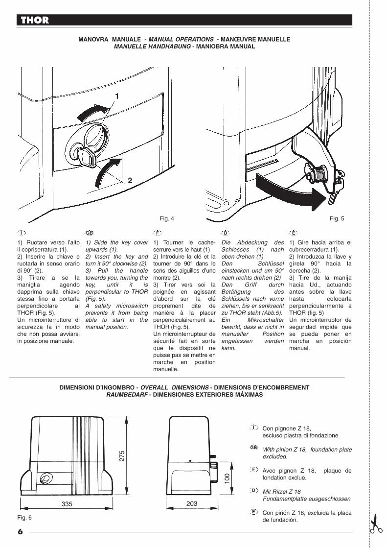
DIMENSIONI D’INGOMBRO - OVERALL DIMENSIONS - DIMENSIONS D’ENCOMBREMENTRAUMBEDARF - DIMENSIONES EXTERIORES MÁXIMAS
MANOVRA MANUALE - MANUAL OPERATIONS - MANŒUVRE MANUELLEMANUELLE HANDHABUNG - MANIOBRA MANUAL
1) Ruotare verso l’altoil copriserratura (1).2) Inserire la chiave eruotarla in senso orariodi 90° (2).3) Tirare a se lamaniglia agendodapprima sulla chiavestessa fino a portarlaperpendicolare alTHOR (Fig. 5).Un microinterruttore disicurezza fa in modoche non possa avviarsiin posizione manuale.
1) Slide the key coverupwards (1).2) Insert the key andturn it 90° clockwise (2).3) Pull the handletowards you, turning thekey, until it isperpendicular to THOR(Fig. 5).A safety microswitchprevents it from beingable to start in themanual position.
1) Tourner le cache-serrure vers le haut (1)2) Introduire la clé et latourner de 90° dans lesens des aiguilles d’unemontre (2).3) Tirer vers soi lapoignée en agissantd’abord sur la cléproprement dite demanière à la placerperpendiculairement auTHOR (Fig. 5).Un microinterrupteur desécurité fait en sorteque le dispositif nepuisse pas se mettre enmarche en positionmanuelle.
Die Abdeckung desSchlosses (1) nachoben drehen (1)Den Schlüsseleinstecken und um 90°nach rechts drehen (2)Den Griff durchBetätigung desSchlüssels nach vorneziehen, bis er senkrechtzu THOR steht (Abb.5).Ein Mikroschalterbewirkt, dass er nicht inmanueller Positionangelassen werdenkann.
1) Gire hacia arriba elcubrecerradura (1).2) Introduzca la llave ygírela 90° hacia laderecha (2).3) Tire de la manijahacia Ud., actuandoantes sobre la llavehasta colocarlaperpendicularmente aTHOR (fig. 5)Un microinterruptor deseguridad impide quese pueda poner enmarcha en posiciónmanual.
I GB F D E
GB
F
D
E
Con pignone Z 18,escluso piastra di fondazione
With pinion Z 18, foundation plateexcluded.
Avec pignon Z 18, plaque defondation exclue.
Mit Ritzel Z 18Fundamentplatte ausgeschlossen
Con piñón Z 18, excluida la placade fundación.
✃
I
Fig. 4 Fig. 5
Fig. 6
335
275
203
100
1
2

7
THOR
(I) ITALIANOATTENZIONE:
Per una corretta sicurezza elettrica e per un buon funzionamento dell’apparecchiaturaè indispensabile effettuare il collegamento a terra.
È estremamente pericoloso utilizzare il motoriduttore senza la prevista messa aterra! (anche durante eventuali prove al banco).
(GB) ENGLISHATTENTION:
To ensure the unit is correctly installed it is important to make sure that earthconnections.
Do not install the gearmotor unit without earthing! (during the tests, too).
(F) FRANÇAISATTENTION:
Pour la securité electrique et pour un bon functionnement de l’appareil, il est indispensableeffectuer les bronchements à terre.
Il est dangereux utilizeur le actionneur motorèducteur sans la mise à terre prevue! (mêmependant des éssais).
(D) DEUTSCHACHTUNG:
Um eine opimale Funktion des Antriebes, sowie die erforderliche elektrische Sichereit des Antriebeszu gewährleisten, ist es zwingend notwendig den Erdleiter anzuschließen.
Weder zu Testzwecken noch in Normalbetrieb darf der Torantrieb ohne Erdung in Betriebgenommen werden.
(E) ESPANOLATTENCIÓN:
Para una correcta seguridad eléctrica y para un buen funcionamiento del aparato, es obligatorioefectuar la conexion a tierra.
Queda extremadamente peligroso utilizar el motorreductor sin la prevista puesta a tierra!(incluso durante eventuales pruebas de banco).

8
THOR
MURATURA DELLA PIASTRA DI FONDAZIONE WALLING THE FOUNDATION PLATEAvvitare a mano per ognuna delle 4 zanche in dotazione 1 dado M 12basso per tutto il filetto.Infilare le quattro zanche nella piastra di fondazione fig. 7Prevedere una o più guaine per il passaggio di cavi elettrici.Inserire nel calcestruzzo la piastra avendo cura di metterlaperfettamente in bolla.È importante rispettare la distanza della piastra di fondazione dallacremagliera (bisogna quindi sapere anzi tempo se sarà saldata alcancello oppure fissata con viti e distanziali), in modo da poter usufruiredel fissaggio asolato del motoriduttore
Screw right down by hand, for each of the 4 fish-tail clamps provided, 1M12 low nut.Insert the four clamps in the foundation plate, Fig. 7.Use one or more sheaths for the passage of the electric cables.Insert the plate in the concrete, taking care to place it perfectly level.It is important to observe the distance of the foundation plate from therack (hence you must know in advance whether it is going to be weldedto the gate or secured with screws and spacers), so you can make use ofthe slotted fixing on the gearmotor.
170
10
170
10
335 0 ÷ 50
33550 ÷ 100
destro - right - droiterechts - der.
sinistro - left- gauchelinks - izq.
I GB
F
D
E
SCELLEMENT DE LA PLAQUE DE FONDATIONVisser à la main pour chacune des agrafes fournies 1 écrouM12 bas jusqu’en bas de la partie filetée.Enfiler les quatre agrafes dans la plaque de fondation (fig. 7).Prévoir une ou plusieurs gaines pour le passage des câblesélectriques.Sceller la plaque dans le ciment en ayant soin de la mettreparfaitement de niveau.Il est important de respecter la distance entre la plaque defondation et la crémaillère (il faut donc savoir en temps utile sielle sera soudée au portail ou bien vissée avec les vis et lesentretoises), de manière à pouvoir utiliser la fixation à fente dumotoréducteur.
EINMAUERN DER FUNDAMENTPLATTEFür jedes der 4 mitgelieferten Verankerungsbeine 1 flache M12Mutter mit Gewinde ganz von Hand anschrauben.Die 4 Verankerungsbeine in die Fundamentplatte einstecken,Abb. 7.Einen oder mehrere Mäntel für den Durchgang vonElektrokabeln vorsehen.Die Platte in den Beton einfügen und perfekt nivellieren.Wichtig ist, dass der Abstand der Fundamentplatte von derZahnstange eingehalten wird (man muss vorher wissen, ob dieZahnstange an das Tor geschweisst oder mit Schrauben undDistanzstücken befestigt wird), so dass der Getriebemotor mitSchlitz befestigt werden kann.
COLOCACIÓN DE LA PLACA DE FUNDACIÓNEnrosque a mano hasta el fondo las cuatro tuercas M 12 bajasen las 4 grapas suministradas de serie.Introduzca las cuatro grapas en la placa de fundación (fig. 7).Disponga de una o varias vainas para pasar los cableseléctricos.Introduzca en el hormigón la placa teniendo cuidado encolocarla perfectamente nivelada.Es importante respetar la distancia de la placa de fundacióndesde la cremallera (por consiguiente, es necesario saber poranticipado si ésta será soldada a la verja, o fijada con tornillo ydistanciadores), para poder aprovechar la las ranuras deregulación de la sujeción del motorreductor.
Fig. 7
Fig. 8
9
THOR
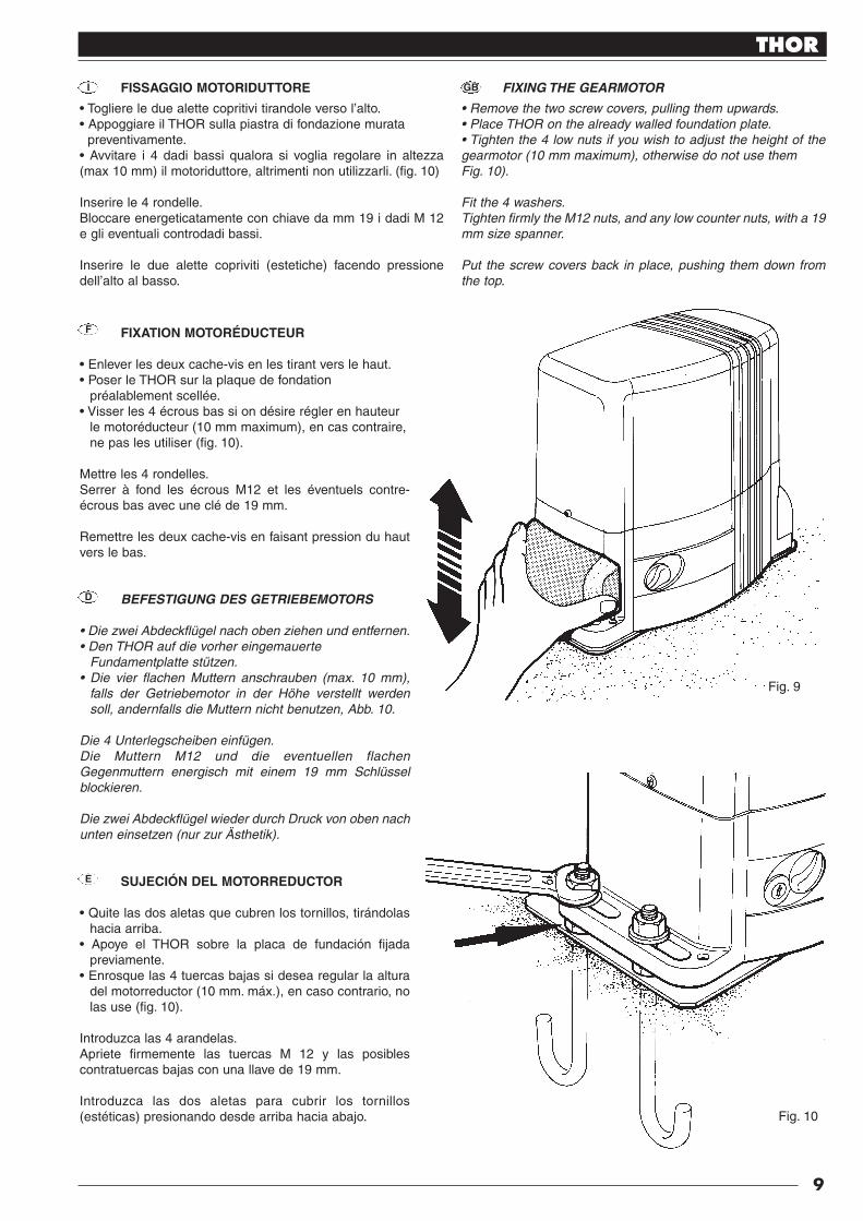
FISSAGGIO MOTORIDUTTORE FIXING THE GEARMOTOR
• Togliere le due alette copritivi tirandole verso l’alto.• Appoggiare il THOR sulla piastra di fondazione murata
preventivamente.• Avvitare i 4 dadi bassi qualora si voglia regolare in altezza(max 10 mm) il motoriduttore, altrimenti non utilizzarli. (fig. 10)
Inserire le 4 rondelle.Bloccare energeticatamente con chiave da mm 19 i dadi M 12e gli eventuali controdadi bassi.
Inserire le due alette copriviti (estetiche) facendo pressionedell’alto al basso.
• Remove the two screw covers, pulling them upwards.• Place THOR on the already walled foundation plate.• Tighten the 4 low nuts if you wish to adjust the height of thegearmotor (10 mm maximum), otherwise do not use them Fig. 10).
Fit the 4 washers.Tighten firmly the M12 nuts, and any low counter nuts, with a 19mm size spanner.
Put the screw covers back in place, pushing them down fromthe top.
FIXATION MOTORÉDUCTEUR
• Enlever les deux cache-vis en les tirant vers le haut.• Poser le THOR sur la plaque de fondation
préalablement scellée.• Visser les 4 écrous bas si on désire régler en hauteur
le motoréducteur (10 mm maximum), en cas contraire,ne pas les utiliser (fig. 10).
Mettre les 4 rondelles.Serrer à fond les écrous M12 et les éventuels contre-écrous bas avec une clé de 19 mm.
Remettre les deux cache-vis en faisant pression du hautvers le bas.
BEFESTIGUNG DES GETRIEBEMOTORS
• Die zwei Abdeckflügel nach oben ziehen und entfernen.• Den THOR auf die vorher eingemauerte
Fundamentplatte stützen.• Die vier flachen Muttern anschrauben (max. 10 mm),
falls der Getriebemotor in der Höhe verstellt werdensoll, andernfalls die Muttern nicht benutzen, Abb. 10.
Die 4 Unterlegscheiben einfügen.Die Muttern M12 und die eventuellen flachenGegenmuttern energisch mit einem 19 mm Schlüsselblockieren.
Die zwei Abdeckflügel wieder durch Druck von oben nachunten einsetzen (nur zur Ästhetik).
SUJECIÓN DEL MOTORREDUCTOR
• Quite las dos aletas que cubren los tornillos, tirándolashacia arriba.
• Apoye el THOR sobre la placa de fundación fijadapreviamente.
• Enrosque las 4 tuercas bajas si desea regular la alturadel motorreductor (10 mm. máx.), en caso contrario, nolas use (fig. 10).
Introduzca las 4 arandelas.Apriete firmemente las tuercas M 12 y las posiblescontratuercas bajas con una llave de 19 mm.
Introduzca las dos aletas para cubrir los tornillos(estéticas) presionando desde arriba hacia abajo.
I GB
F
D
E
Fig. 9
Fig. 10

10
THOR
FIXATION DE LA CRÉMAILLÈRE
Sélectionner le “fonctionnement manuel”.Mettre en appui sur l’engrenage le 1er élément de la crémaillère(fig. 11) et le bloquer au portail en faisant coulisser ce dernier.Pour un positionnement correct des autres éléments, il faut utiliserun élément faisant fonction de contre-crémaillère.Il est important qu’il y ait un jeu d’au moins 1 mm entre lacrémaillère et l’engrenage de manière que le poids du portail nepèse jamais sur le motoréducteur.
Positionner de manière approximative les deux pattes de supportpour microinterrupteur de fin de course sur la crémaillère et, enagissant manuellement sur le portail, procéder à la fixationdéfinitive avec les goujons fournis (fig. 12).
Attention: quand la patte de support du microinterrupteurintervient sur le ressort du motoréducteur, le portail coulisseencore sur 50 mm environ. Positionner donc les pattes en avantd’autant pour éviter que le portail se coince.
BEFESTIGUNG DER ZAHNSTANGE
Den THOR auf “manuellen Betrieb” stellen.Das 1. Zahnstangenelement auf das Zahnrad stützen (Abb. 11)und am Tor blockieren, dabei den Flügel gleiten lassen.Für das korrekte Positionieren der anderen Elemente muss einTeil benutzt werden, das als Gegenzahnstange dient.Wichtig ist, dass zwischen Zahnstange und Zahnrad ein Spiel vonmindestens 1 mm ist, so dass das Torgewicht nie auf demGetriebemotor liegt.
Die zwei mitgelieferten Anschlagbügel ungefähr an der Zahnstangeanordnen und, indem das Tor manuell betätigt wird, mit denmitgelieferten Stiftschrauben endgültig befestigen (Abb. 12).
Berücksichtigen, dass das Tor noch etwa 50 mm gleitet, nachdemder Anschlagbügel auf die Feder des Getriebemotors trifft. Daherdie richtige Vorverstellung der Bügel einhalten, damit dasKlemmen des Tors verhindert wird.
FIJACIÓN DE LA CREMALLERA
Coloque el THOR en “funcionamiento manual”.Apoye sobre el engranaje el 1° elemento de la cremallera (fig. 11)y bloquéelo a la verja, haciendo correr la hoja.Para posicionar correctamente los demás componentes, use unelemento que cumpla la función de contracremallera.Es importante que entre la cremallera y el engranaje haya unjuego de 1 mm como mínimo, para que el motorreductor nuncasoporte el peso de la verja.
Coloque aproximadamente las bridas de tope suministradas deserie sobre la cremallera y, actuando manualmente sobre la verja,fíjelas definitivamente con los tornillos sin cabeza de serie (fig. 12).
Tenga en cuenta que cuando la brida de tope interviene sobre elmuelle del motorreductor, la verja se deslizará por otros 50 mmaprox. Por lo tanto, instale las bridas en la posición exacta paraque la verja no se trabe.
F
D
E
Fig. 12
FISSAGGIO DELLA CREMAGLIERA
Predisporre il THOR in “funzionamento manuale”.Appoggiare sull’ ingranaggio il 1° elemento di cremagliera fig.11 e bloccarlo al cancello, facendo scorrere l’anta.Per un corretto posizionamento degli altri elementi è necessarioutilizzare un elemento che funzioni da controcremaglieria.È importante che fra cremaglieria ed ingranaggio ci sia un giocodi almeno 1 mm. in modo che il peso del cancello non gravi maisul motoriduttore.
Posizionare in modo approssimativo le due staffe di finecorsa indotazione, sulla cremagliera, ed agendo manualmente sul cancello,procedere al fissaggio definitivo con i grani in dotazione (fig. 12).
Tenere presente che quando la staffa di finecorsa intervienesulla molla del motoriduttore, il cancello scorrerà per altri 50mm. circa. Tenere quindi il giusto anticipo delle staffe ondeevitare l’incaglio del cancello.
FIXING THE RACK
Select the “manual” functioning mode.Place the first rack element on the gear (Fig. 11), and lock it tothe gate by letting it slide along.To ensure correct positioning of the other elements it is necessaryto use an element that functions as a counter-rack,.It is important that there be a certain amount of play betweenrack and gear (at least 1 mm) so the gate’s weight never bearsdown on the gearmotor.
Roughly position the two limit switch brackets (provided) on therack and, manually moving the gate, fix them definitely with thedowels provided (fig. 12).
Attention: when the microswitch bracket operates the gearmotorspring, the gate will slide about another 50 mm so make sure thebrackets’ timing is correct to avoid the gate getting stuck.
I GB
Fig. 11

11
THOR
Fig. 13
REGOLAZIONE DELLA FRIZIONE ELETTRONICATH1551 - TH1551/110
La regolazione della coppia è di tipo elettronico. (Fig. 13)Attenersi alle istruzioni allegate della centralina elettronica.EFFETTUARE TUTTE LE REGOLAZIONI RISPETTANDO LENORMATIVE VIGENTI.
ADJUSTING THE ELECTRONIC CLUTCHTH1551 - TH 1551/110
The torque is electronically adjusted (Fig. 13).Follow the instuctions enclosed with the electronic controlunit. PERFORM ALL ADJUSTMENTS IN COMPLIANCEWITH CURRENT REGULATIONS.
RÉGLAGE DE L’EMBRAYAGE ÉLECTRONIQUETH1551 - TH1551/110
Le réglage du couple est de type électronique (Fig. 13).Suivre les instuctions fournies avec la centrale élec-tronique.EFFECTUER TOUS LES RÉGLAGES EN RESPECTANT LESNORMES EN VIGUEUR.
EINSTELLUNG DER ELEKTRONISCHEN KUPPLUNGTH1551 - TH1551/110
Die Einstellung des Drehmoments erfolgt elektronisch(Abbildung 13).Halten Sie sich an die mit der Steuereinheit geliefertenAnweisungen.ALLE EINSTELLUNGS-ARBEITEN UNTER BEACHTUNGDER GELTENDEN VORSCHRIFTEN VORNEHMEN.
REGULACIÓN DEL EMBRAGUE ELECTRÓNICOTH1551 - TH1551/110
La regulación del par es de tipo electrónico (Fig. 13).Seguir las instrucciones adjuntas de la centralinaelectrónica.EFECTUARTODAS LAS REGULACIONES RESPETANDOLAS NORMAS VIGENTES.
I
GB
F
D
E

N° TH1551 TH1561 TH1551/110 TH2251 TH2261
1
2
3
4
5
6
7
8
9
10
11
12
13
14
15
16
17
18
19
20
21
22
23
24
25
26
27
28
29
30
31
32
33
34
35
36
37
38
39
40
41
42
43
44
45
46
47
48
49
50
51
52
53
54
55
56
57
58
59
60
61
62
63
64
65
66
67
68
69
70
71
72
73
74
75
76
77
78
79
80
81
82
83
84
85
BMGTHA 34567
BMGTHC 34567
PPD1179 4540
BMMSA 14567
PPD1178 4540
CM-B 1630
PMD0166 4610
G6X50 5123
PPD1184 4540
BPCO2 4540
THA5
TRA-G 1025
MO-D 2640
MICROI-C 1617
MICROI 1617
30U450A 0727
BMCI 4567
PEDS65A 4650
BMCS 24567
PPD1180 4540
PPD1181 4540
PMD0133 4610
PMCU3010 4630
PECR1175 4610
PPD1182 4540
PPD1183 4540
-
PMCU6 4630
-
-
-
-
V6X120 5102
PMD0167 4610
MO-N 5501
PMCU3 4630
PMCSE30 4630
PMDRC5 4610
PMD0131A 4610
PMC128 4630
PMCS10 4630
PPD0120 4540
PMCU10 4630
GOR-Y 5501
BMFP010A 34567
V5X15-A 5102
PMD0628 4610
R12C 5120
PMD0139 4610
PMD0140 4610
MMCOI 2620
V4.2X9.5 5101
V2.9X16 5101
PMCAC1 4630
V4X5 5102
V2.9X6.5A 5101
V3.5X20 5101
EMRO 4870
V4.8X16 5101
R04E 5120
V2.9X9.5A 5101
GOR-L1 5501
RO3 5120
-
CF0193 5320
CT200 5320
V4X8 5105
V4.2X9.5B 5101
BPC 4540
D6 5102
D12B 5110
D12 5110
EN 4870
G6X14 5123
R12 5120
V6.3X25 5101
C3VF 2015
GOR-M 5501
CGU8B 5310
PMD0885 4610
PMD0886 4610
V10X12A 5102
PMD0165 4610
GOR-W 5501
PMCS6 4630
BMGTHA 34567
BMGTHC 34567
PPD1179 4540
BMMSA 14567
PPD1178 4540
CM-B 1630
PMD0166 4610
G6X50 5123
PPD1184 4540
-
-
-
MO-D 2640
MICROI-C 1617
MICROI 1617
-
BMCI 4567
PEDS652A 4650
BMCS 24567
PPD1180 4540
PPD1181 4540
PMD0133 4610
PMCU3010 4630
PECR1175 4610
PPD1182 4540
PPD1183 4540
M12V 1850
PMCU6 4630
MMCP 2620
MMCT 2620
-
-
V6X120 5102
PMD0167 4610
MO-N 5501
PMCU3 4630
PMCSE30 4630
PMDRC5 4610
PMD0131A 4610
PMC128 4630
PMCS10 4630
PPD0120 4540
PMCU10 4630
GOR-Y 5501
BMFP010A 34567
V5X15-A 5102
PMD0628 4610
R12C 5120
PMD0139 4610
PMD0140 4610
MMCOI 2620
V4.2X9.5 5101
V2.9X16 5101
PMCAC1 4630
V4X5 5102
V2.9X6.5A 5101
V3.5X20 5101
-
V4.8X16 5101
R04E 5120
-
GOR-L1 5501
RO3 5120
-
CF0193 5320
-
V4X8 5105
V4.2X9.5B 5101
BPC 4540
D6 5102
D12B 5110
D12 5110
EN 4870
G6X14 5123
R12 5120
V6.3X25 5101
-
GOR-M 5501
CGU8B 5310
PMD0885 4610
PMD0886 4610
V10X12A 5102
PMD0165 4610
GOR-W 5501
PMCS6 4630
BMGTHA 34567
BMGTHC 34567
PPD1179 4540
BMMSA 14567
PPD1178 4540
CM-B 1630
PMD0166 4610
G6X50 5123
PPD1184 4540
BPCO2 4540
THA5
TRA-H 1025
MO-D 2640
MICROI-C 1617
MICROI 1617
80U450 0727
BMCI 4567
PEDS651A 4650
BMCS 24567
PPD1180 4540
PPD1181 4540
PMD0133 4610
PMCU3010 4630
PECR1175 4610
PPD1182 4540
PPD1183 4540
-
PMCU6 4630
-
-
-
-
V6X120 5102
PMD0167 4610
MO-N 5501
PMCU3 4630
PMCSE30 4630
PMDRC5 4610
PMD0131A 4610
PMC128 4630
PMCS11 4630
PPD0120 4540
PMCU10 4630
GOR-Y 5501
BMFP010A 34567
V5X15-A 5102
PMD0628 4610
R12C 5120
PMD0139 4610
PMD0140 4610
MMCOI 2620
V4.2X9.5 5101
V2.9X16 5101
PMCAC1 4630
V4X5 5102
V2.9X6.5A 5101
V3.5X20 5101
-
V4.8X16 5101
R04E 5120
V2.9X9.5A 5101
GOR-L1 5501
RO3 5120
-
CF0193 5320
CT200 5320
V4X8 5105
V4.2X9.5B 5101
BPC 4540
D6 5102
D12B 5110
D12 5110
EN 4870
G6X14 5123
R12 5120
V6.3X25 5101
C3VF 2015
GOR-M 5501
CGU8B 5310
PMD0885 4610
PMD0886 4610
V10X12A 5102
PMD0165 4610
GOR-W 5501
PMCS6 4630
BMGTHA 34567
BMGTHC 34567
PPD1179 4540
BMMSA 14567
PPD1178 4540
CM-B 1630
PMD0166 4610
G6X50 5123
PPD1184 4540
BPCO2 4540
THA6
TRA105 1030
MO-D 2640
MICROI-C 1617
MICROI 1617
30U450A 0727
BMCI 4567
PEDS658 4650
BMCS 24567
PPD1180 4540
PPD1181 4540
PMD0133 4610
PMCU3010 4630
PECR1176 4610
PPD1182 4540
PPD1183 4540
-
PMCU6 4630
-
-
-
-
V6X120 5102
PMD0167 4610
MO-N 2640
PMCU3 4630
PMCSE30 4630
PMDRC5 24610
PMD0131A 4610
PMC128 4630
PMCS10 4630
PPD0120 4540
PMCU10 4630
GOR-Y 5501
BMFP010A 34567
V5X15-A 5102
PMD0628 4610
R12C 5120
PMD0139 4610
PMD0140 4610
MMCOI 2620
V4.2X9.5 5101
V2.9X16 5101
PMCAC1 4630
V4X5 5102
V2.9X6.5A 5101
V3.5X20 5101
EMRO 4870
V4.8X16 5101
R04E 5120
V2.9X9.5-A 5101
GOR-L1 5501
R03 5120
-
CF0193 5320
CT200 5320
V4X8 5105
V4.2X9.5B 5101
BPC 4540
D6 5102
D12B 5110
D12 5110
EN 4870
G6X14 5123
R12 5120
V6.3X25 5101
C3VF 2015
GOR-M 5501
CGU8B 5310
PMD0885 4610
PMD0886 4610
V10x12A 5102
PMD0165 4610
GOR-W 5501
PMCS6 4630
BMGTHA 34567
BMGTHC 34567
PPD1179 4540
BMMSA 14567
PPD1178 4540
CM-B 1630
PMD0166 4610
G6X50 5123
PPD1184 4540
BPCO2 4540
-
-
MO-D 2640
MICROI-C 1617
MICROI 1617
-
BMCI 4567
PEDS652A 4650
BMCS 24567
PPD1180 4540
PPD1181 4540
PMD0133 4610
PMCU3010 4630
PECR1175 4610
PPD1182 4540
PPD1183 4540
M12V 1850
PMCU6 4630
MMCP 2620
MMCT 262
-
G8X10 5123
V6X120 5102
PMD0167 4610
MO-N 2640
PMCU3 4630
PMCSE30 4630
PMDRC5 24610
PMD0131A 4610
PMC128 4630
PMCS10 4630
PPD0120 4540
PMCU10 4630
GOR-Y 5501
BMFP010A 34567
V5X15-A 5102
PMD0628 4610
R12C 5120
PMD0139 4610
PMD0140 4610
MMCOI 2620
V4.2X9.5 5101
V2.9X16 5101
PMCAC1 4630
V4X5 5102
V2.9X6.5A 5101
V3.5X20 5101
-
V4.8X16 5101
R04E 5120
-
GOR-L1 5501
R03 5120
-
CF0193 5320
-
V4X8 5105
V4.2X9.5B 5101
BPC 4540
D6 5102
D12B 5110
D12 5110
EN 4870
G6X14 5123
R12 5120
V6.3X25 5101
-
GOR-M 5501
CGU8B 5310
PMD0885 4610
PMD0886 4610
V10x12A 5102
PMD0165 4610
GOR-W 5501
PMCS6 4630
12
THOR
12

THOR
I GB
F D E
CATALOGO RICAMBI SPARE PARTS CATALOGUE
CATALOGUE DES RECHANGES ERSATZTEILKATALOG CATÁLOGO DE RECAMBIOS
13

14
THOR

15
THOR

(secondo Direttiva 98/37/EC, Allegato II, parte B) (according to 98/37/EC Directive, Enclosure II, part B)
Numero /Number : 176/TH Data / Date: 9/2003 Revisione / Revision: 1
Il sottoscritto Lauro Buoro, Amministratore Delegato, dichiara che il prodotto:The undersigned Lauro Buoro, General Manager, declares that the product:Nome produttore / Producer name: NICE s.p.a.Indirizzo / Address: Via Pezza Alta 13, 31046 Z.I. Rustignè - ODERZO - ITALYTipo / Type: Motoriduttore elettromeccanico 120/230 V a.c. per cancelli scorrevoli
Electromechanical gearmotor for sliding doorsModello / Model: TH1551, TH2251, TH1561, TH2261Accessori / Accessories: Scheda PIU’, Ricevitore opzionale mod. K, BIO, FLO, FLOR
PIU’ Expansion card, Radio receivers mod. K, BIO, FLO, FLORRisulta conforme a quanto previsto dalle seguenti direttive comunitarie/Appears to be in conformity with the following community (EEC) regulationsRiferimento n° TitoloReference n° Title73/23/CEE DIRETTIVA BASSA TENSIONE/ Low Voltage Directive89/336/CEE DIRETTIVA COMPATIBILITA’ ELETTROMAGNETICA (EMC) / EMC Electromagnetic Compatibility Directive98/37/CE (EX 89/392/CEE) DIRETTIVA MACCHINE/Machinery DirectiveRisulta conforme a quanto previsto dalle seguenti Norme armonizzate / Appears to be in conformity with the following Harmonized standards regulationsRiferimento n° Edizione Titolo Livello di valutazione ClasseReference n° Issue Title Estimate level ClassEN60335-1 04/1998 Sicurezza degli apparecchi elettrici d’uso domestico e similare – Norme generali.
Safety of household and electrical appliances – General requirementsEN60204-1 09/1993 Sicurezza del macchinario-Equipag. elettrico delle macchine-Parte 1:Reg.generali
Safety of machinery-Electrical equipment of machines-Part 1:General requirementsEN55022 09/1998 Apparecchi per la tecnologia dell’informazione. B
Caratteristiche di radiodisturbo. Limiti e metodi di misuraInformation technology equipment – Radio disturbance characteristicsLimits and methods of measurement
ENV50204 04/1996 Campo elettromagnetico irradiato dai radiotelefoni numerici - Prova di immunità. 10V/m ARadiated electromagnetic fields from digital radio telephones - Immunity test
EN61000-3-2-3 03/1995 Parti 2-3: Armoniche/Flicker AParts 2-3: Harmonic/FlickerCompatibilità elettromagnetica (EMC) / Electromagnetic compatibility (EMC)Parte 4: Tecniche di prova e di misura / Part 4: Testing and measurement techniques
EN61000-4-2 09/1996 Parte 2: Prove di immunità a scarica elettrostatica 6KV, 8KV BPart 2: Electrostatic discharge immunity test
EN61000-4-3 11/1997 Parte 3: Prova d’immunità sui campi irradiati a radiofrequenza 10V/m, APart 3: Radiated, radio-frequency, electromagnetic field immunity test
EN61000-4-4 09/1996 Parte 4: Test sui transienti veloci/ immunità ai burst 2KV, 1KV BPart 4: Electrical fast transient/burst immunity test.
EN61000-4-5 06/1997 Parte 5: Prova di immunità ad impulsi 4KV, 2KV BPart 5: Surge immunity test
EN61000-4-6 11/1997 Parte 6: Immunità ai disturbi condotti, indotti da campi a radiofrequenza 10V APart 6: Immunity to conducted disturbances, induced by radio-frequency fields.
EN61000-4-8 06/1997 Parte 8: Prova di immunità a campi magnetici a frequenza di rete 30A/m APart 8: Power frequency magnetic field immunity test.
EN61000-4-11 09/1996 Parte 11: Prove di immunità a buchi di tensione, brevi interruzioni e variazioni di tensione B-CPart 11: Voltage dips, short interruptions and voltage variations immunity tests
Risulta conforme a quanto previsto dalle altre norme e/o specifiche tecniche di prodotto / Appears to be in conformity with the other standards and/orproduct technicalRiferimento n° Edizione Titolo Livello di valutazione ClasseReference n° Issue Title Esimate level ClassEN 12445 11/2000 Industrial, commercial and garage doors and gates - Safety in use of power
operated doors - Test methodsEN 12453 11/2000 Industrial, commercial and garage doors and gates - Safety in use of power
operated doors - RequirementsInoltre dichiara che non è consentita la messa in servizio del prodotto suindicato finché la macchina, in cui il prodotto stesso èincorporato, non sia identificata e dichiarata conforme alla direttiva 98/37/CE/He declares, moreover, that it is not allowed to use the abovementioned product until the machine, in which this product is incorporated, has been identified and declared in conformity with the regulation 98/37/CE.
P.S.: Il prodotto suindicato si intende parte integrante di una delle configurazioni di installazione tipiche, come riportato nei nostricataloghi generali / The above mentioned product is meant integral part of the of one of the installation configuration as shown on our general catalogues
Oderzo, 11 Settembre 2003 (Amministratore Delegato) (General Manager)
Lauro Buoro
Dichiarazione CE di conformità / EC declaration of conformity
ISTT
H 4
865
RE
V. 0
09 -
04/
10/2
004
Nice SpA
Oderzo TV Italia
Via Pezza Alta, 13 Z.I. Rustignè
Tel. +39.0422.85.38.38
Fax +39.0422.85.35.85
Nice BelgiumLeuven (Heverlee) BTel. +32.(0)16.38.69.00Fax +32.(0)[email protected]
Nice España Madrid ETel. +34.9.16.16.33.00Fax [email protected]
Nice France Buchelay FTel. +33.(0)1.30.33.95.95 Fax +33.(0)[email protected]
Nice Polska Pruszków PLTel. +48.22.728.33.22Fax [email protected]
www.niceforyou.com
A termini di legge ci riserviamo la proprietà di questo manuale con divieto di riprodurlo o di renderlo comunque noto a terzi o a ditte concorrenti senza nostra autorizzazione.

MODELLI E CARATTERISTICHE - MODELS AND CHARACTERISTICS - MODÈLES ET CARACTÉRISTIQUESMODELLE UND MERKMALE - MODELOS Y CARACTERÍSTICAS
DATI TECNICI - TECHNICAL DATA TECHNISCHE DATEN- DONNÉES TECHNIQUES - - DATOS TÉCNICOS
THOR 1551
THOR 1561
Motoriduttore percancelli fino a 1500Kg, motore 230 Vautoventilato centraleincorporata.
Motoriduttore percancelli fino a 1500Kg, motore 380 Vautoventilato, senzacentrale.
Gearmotor for
gates up to 1500 kg,
230 V self-ventilated
motor, built-in control
unit.
Gearmotor for gates
up to 1500 kg, 380 V
self-ventilated motor,
without a
control unit.
Motoréducteurpour portails jusqu’à1500 kg, moteur 230 Vautoventilé, centraleincorporée.
Motoréducteur pourportails jusqu’à 1500kg, moteur 380 Vautoventilé, sanscentrale.
Getriebemotor fürTore bis 1500 kg,230V Motor mitEigenbelüftung, miteingebauter.
Getriebemotor für Torebis 1500 kg, 380VMotor mitEigenbelüftung, ohneSteuerzentrale
Motorreductorpara verjas de hasta1500 kg, motor de230V autoventilado,central incorporada
Motorreductor paraverjas de hasta 1500kg, motor de 380Vautoventilado, sincentral.
* Con pignone Z = 18 -*With pinion Z = 18 - * Avec pignon Z = 18 -* Mit Ritzel Z = 18 - * Con piñón Z = 18
I GB F D E
Alimentazione - Power supply - Alimentation
Speisung - Alimentaciòn
Corrente - Current - Courant - Strom - Intensidad
Potenza assorbita - Absorbed powerPuissance absorbée - Aufgenommene LeistungPotencia absorbida
Grado di protezione - Protection levelIndice de protection - SchutzgartGrado de protección
Condensatore incorporato - Condenser built-inCondensateur incorporé - Kondensator eingebautCondensator incorporado
Coppia - Torque - Couple - Drehmoment - Par
Velocità - Speed - Vitesse
Geschwindigkeit - Velocidad
Spinta max. - Maximum thrust - Pousèe maximum
Max. Schub - Empuje max.
Peso max cancello - Max. weight of gatePoids max. portail - Max. Gewicht Tor
Peso maximo de la cancela
Temperatura di esecizio - Working temperatureTempérature de service - BetriebstemperaturTemperatura de servicio
Classe di isolamento - Insulation classClasse d’isolement - IsolierungsklasseClase de aislamiento
Termoprotezione - Thermal protection - Protection
Thermique - Wärmeschutz - Termoproteccion
Ciclo di lavoro - Working cycle - Cycle de travail
Arbeitszyklus - Ciclo de trabajo
Peso motore - Motor weight - Poids moteur
Motorgewicht - Peso del motor
Vac 50 Hz
Vdc
A
W
µF
IP
N•m
m/s
N
kg
°C (Min. / Max.)
°C
%
kg
230/50
Vdc
3.50
650
30
30
0.16*
800
1500
1
40
12.5
380/50
Vdc
1.20
700
-
60
1000
50
12
Unità di misura - Unit of measureUnité de mesure
Maßeinheit - Unidad de medidaTH 1551 TH 1561
380/50
Vdc
1.20
700
-
35
1000
50
13
TH2251 TH2261
120/60
Vdc
7
650
80
25
0,19
600
1500
1
40
12,5
TH1551/110
140°
44
230/50
Vdc
3.50
900
30
35
0.16*
1000
2200
40
13
-20 +50° ÷ °
THOR 2251
THOR 2261
Motoriduttore percancelli fino a 2200kg, motore 230 Vautoventilato centraleincorporata
Motoriduttore percancelli fino a 2200kg, motore 380 Vautoventilato,senza centrale.
Gearmotor for
gates up to 2200 kg,
230 V self-ventilated
motor, built-in control
unit.
Gearmotor for gates
up to 2200 kg, 380 V
self-ventilated motor,
without a
control unit.
Motorèducteurpour portails jusqu’à2200 kg, moteur 230 Vautoventilè, centraleincorporèe.
Motorèducteur pourportails jusqu’à 2200kg, moteur 380 Vautoventilè,sans centrale
Getriebemotor fürTore bis 2200 kg,230V Motor mitEigenbel_ftung, miteingebauter.
Getriebemotor für Torebis 2200 kg, 380VMotor mitEigenbel_ftung, ohneSteuerzentrale.
Motorreductorpara verjas de hasta2200 kg, motor de230V autoventilado,centralincorporada.
Motorreductor paraverjas de hasta 2200kg, motor de 380Vautoventilado,sin central.
1F F
ISTTH1 4865 REV.0

Fig. 13
REGOLAZIONE DELLA FRIZIONE ELETTRONICATH1551 - TH1551/110
La regolazione della coppia è di tipo elettronico. (Fig. 13)Attenersi alle istruzioni allegate della centralina elettronica.EFFETTUARE TUTTE LE REGOLAZIONI RISPETTANDO LENORMATIVE VIGENTI.
ADJUSTING THE ELECTRONIC CLUTCH
TH1551 - TH 1551/110
The torque is electronically adjusted (Fig. 13).
Follow the instuctions enclosed with the electronic control
unit. PERFORM ALL ADJUSTMENTS IN COMPLIANCE
WITH CURRENT REGULATIONS.
RÉGLAGE DE L’EMBRAYAGE ÉLECTRONIQUETH1551 - TH1551/110
Le réglage du couple est de type électronique (Fig. 13).Suivre les instuctions fournies avec la centrale élec-tronique.EFFECTUER TOUS LES RÉGLAGES EN RESPECTANT LESNORMES EN VIGUEUR.
EINSTELLUNG DER ELEKTRONISCHEN KUPPLUNG
TH1551 - TH1551/110
Die Einstellung des Drehmoments erfolgt elektronisch
(Abbildung 13).
Halten Sie sich an die mit der Steuereinheit gelieferten
Anweisungen.
ALLE EINSTELLUNGS-ARBEITEN UNTER BEACHTUNG
DER GELTENDEN VORSCHRIFTEN VORNEHMEN.
REGULACIÓN DEL EMBRAGUE ELECTRÓNICOTH1551 - TH1551/110
La regulación del par es de tipo electrónico (Fig. 13).Seguir las instrucciones adjuntas de la centralinaelectrónica.EFECTUARTODAS LAS REGULACIONES RESPETANDOLAS NORMAS VIGENTES.
I
GB
F
D
E
IST
TH
14865
RE
V.0

control unit
robo, thor, ottoInstructions and warnings for the fitter
Istruzioni ed avvertenze per l’installatore
Instructions et recommandations pour l’installateur
Anweisungen und Hinweise für den Installateur
Instrucciones y advertencias para el instalador
Instrukcje i uwagi dla instalatora
Aanwijzingen en aanbevelingen voor de installateur

2
robo,th

NL
or,otto
GB
I
F
D
E
PL

4
control unit gearmotorsrobo, thor, otto
Warnings:
This manual has been especially written for use byqualified fitters. No information given in this manual can beconsidered as being of interest to end users!This manual only refers to this control unit and may not beused for different products.Do not install the unit before you have read all the instructions at leastonce.
!
Table of contents: page
1 Description of the product 5
2 Installation 62.1 Typical system layout 62.2 Electrical connections 62.2.1 Electrical diagram 72.2.2 Description of connections 72.2.3 Phototest 82.2.4 Checking connections 9
3 Adjustments 9
4 Testing 10
5 Operating modes 11
page
6 Programmable functions 116.1 Description of functions 12
7 Using 2 control units on opposed leafs 13
8 Accessories 14
9 Maintenance 14
10 Disposal 14
11 What to do if... 15
12 Technical specifications 15

GB
5
1) Description of the product:This gate and door automation unit controls the ROBO, OTTO andTHOR gearmotors with single-phase alternating current.The control unit varies depending on the type of gearmotor to control,e.g.: Force Adjustment, Gate Open Indicator and Courtesy Light.It also features a series of functions that can be selected by “Dip-Switches” (mini-switches) and adjustments performed by Trimmers.
The control unit features input status Led’s located near such inputs,while another Led near the microprocessor indicates that the internallogic works correctly.
To make it easier to recognise the various parts, fig.1 shows themain components.
LMNOP
J
QRST
V U
I
X
W
YHG
FZ
EDCBA
CH
P.P.
AP
FOTO
FCA
FCCOK
Function selection Dip-SwitchForce adjustment trimmerWorking Time TL adjustment trimmerPause Time TP adjustment trimmerTerminal board for aerial and 2nd channelRADIO board slotInput status LED’sInput/output control terminal board“Common” relayPower input terminal board / Flashing lightPrimary transformer connectorLine fuse (5A)“Courtesy Light” output connector (only on OTTO)Motor power outputCapacitor slot connector“Torque” relayTriac “Courtesy Light” (only on OTTO)Triac CloseTriac OpenSecondary transformer connectorFCA / FCC limit switch inputLow voltage rapid fuse (500mA)PIU board slotOK LedMicroprocessor
ABCDEFGHIJLMNOPQRSTUVWXYZ
1
Product Code* Control Unit Code* Additional Function
ROBORO1000RO1020
ROA3 Force adjustment Trimmer
RO1010 ROA4 “Torque” Relay
THOR TH1551 THA5 Force adjustment TrimmerTH2251 THA6 “Torque” Relay
OTTO OT21 OTA1 “Courtesy Light” output
* = add to code V1 for the 120 V 50/60 Hz version.
6
2.1) Typical system layout
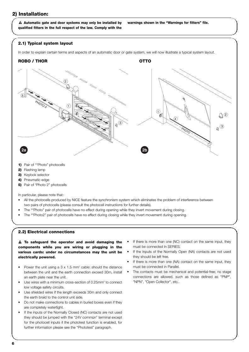
In order to explain certain terms and aspects of an automatic door or gate system, we will now illustrate a typical system layout.
ROBO / THOR OTTO
1) Pair of ““Photo” photocells2) Flashing lamp3) Keylock selector4) Pneumatic edge5) Pair of “Photo 2” photocells
In particular, please note that:• All the photocells produced by NICE feature the synchronism system which eliminates the problem of interference between
two pairs of photocells (please consult the photocell instructions for further details).• The ““Photo” pair of photocells have no effect during opening while they invert movement during closing.• The ““Photo2” pair of photocells have no effect during closing while they invert movement during opening.
Automatic gate and door systems may only be installed byqualified fitters in the full respect of the law. Comply with the
warnings shown in the “Warnings for fitters” file.!
2) Installation:
2a 2b
PHOTO
PHOTO
PHOTO 2
5
3
2
1
3
4
PHOTO
21
2.2) Electrical connections
To safeguard the operator and avoid damaging thecomponents while you are wiring or plugging in thevarious cards: under no circumstances may the unit beelectrically powered.
• Power the unit using a 3 x 1.5 mm2 cable: should the distancebetween the unit and the earth connection exceed 30m, installan earth plate near the unit.
• Use wires with a minimum cross-section of 0.25mm2 to connectlow voltage safety circuits.
• Use shielded wires if the length exceeds 30m and only connectthe earth braid to the control unit side.
• Do not make connections to cables in buried boxes even if theyare completely watertight.
• If the inputs of the Normally Closed (NC) contacts are not usedthey should be jumped with the “24V common” terminal exceptfor the photocell inputs if the phototest function is enabled, forfurther information please see the “Phototest” paragraph.
• If there is more than one (NC) contact on the same input, theymust be connected in SERIES.
• If the inputs of the Normally Open (NA) contacts are not usedthey should be left free.
• If there is more than one (NA) contact on the same input, theymust be connected in Parallel.
• The contacts must be mechanical and potential-free; no stageconnections are allowed, such as those defined as "PNP","NPN", "Open Collector", etc..
!

GB
7
2.2.1) Electrical diagram
2.2.2) Description of connections
A brief description of the possible control unit output connections follows.
Terminals Functions Description
1-2 : Power input = Mains power line
3-4 : Flashing light = Output for connecting flashing light to mains voltage (max. 40W)
5-6 : 24 Vac = 24Vac output to 24Vac services (Photo, Radio, etc.) Max. 200mA
7 : Common = Common for all inputs
8 : Gate open indicator = Max. 24 Vac output for gate open indicator 2W (Not used on OTTO)
9 : Stop = Input for stopping the manoeuvre with a brief reverse phase
10 : Photo = Input for safety devices (photocells, pneumatic edges)
11 : Step-by-step (PP) = Input for cyclic functioning (“Open” - “Stop” - “Close” - “Stop”)
12 : Open = Input for opening
13 : Close = Input for closing
41-42 : 2nd Radio Ch = Output for the second radio receiver channel if there is one
43-44 : Aerial = Input for the radio receiver aerial
3

8
2.2.3) Phototest
“Phototest” is the best possible solution for safety devices in termsof reliability and it puts the control unit and safety photocells in“category 2” according to UNI EN 954-1 standard (ed. 12/1998).Before every manoeuvre is begun, the relative safety devices arechecked and only if everything is in order will the manoeuvre start.Should the test be unsuccessful (the photocell is blinded by the sun,cables have short circuited, etc.) the failure is identified and themanoeuvre is not carried out.
To obtain the Phototest function:• Using the additional “PIU” board.• Setting Dip Switch 10 to ON • Creating a special layout in the safety device connections as
shown in fig. 4a so that the photocell transmitters are no longerdirectly powered by the service output but from terminals 7 and8 of the “PIU” board. The maximum current that the “PIU” boardcan use on the “Phototest” output is 100mA (2 pairs of nicephotocells)
• Powering the receivers directly from the service output of thecontrol unit (terminals 5-6).
If at a later time the Phototest function is no longer required, lower Dip
Switch 10 and modify the connection layout as shown in fig. 4b.
The photocells are tested as follows: when movement is required, itis first checked that all the receivers involved in the movement givetheir consent, then power to the transmitters is disconnected afterwhich it is checked that all the receivers signal the fact by removingtheir consent; the transmitters are then powered and the consent ofall the receivers is verified once more. Only if this sequence issuccessfully carried out will the manoeuvre be performed.Synchronism should always be activated on the two transmitters bycutting the jumpers; this is the only way of ensuring that the twopairs of photoelectric cells do not interfere with one another. Check the instructions in the photocell manual regardingsynchronised operation.
If a “Phototest” input is not used (e.g.: Photo2) but the “phototest”function is required, jumper the unused input as shown in fig. 4c.
“Photo” and “Photo2” with “Phototest”
“Photo” and “Photo2” without “Phototest”
“Photo” with “Phototest”
4a
4b
4c

GB
9
2.2.4) Checking connections
The following operations entail working on live circuits; most ofthese run on extra-low safety voltage so they are not dangerous butsome are contain mains voltage which means they are HIGHLYDANGEROUS! Pay the greatest of attention to what you are doingand NEVER WORK ALONE!
• Power the unit and check that voltage between terminals 5-6 isapprox. 24 Vac.
• Check that the “OK” Led flashes rapidly for a few moments andthen that it flashes at a regular frequency.
• Now check that the Led’s relative to the N.C. (Normally Closed)contacts are on (all safety devices active) and that the Led’srelative to the N.A. (Normally Open) inputs are off (no commandpresent); if this is not the case, check the connections of thevarious devices and make sure they are in good working order.The STOP input switches off both FCA and FCC.
• Make sure the limit switches are connected properly; move thelimit switch lever and check that the relative limit switch cuts inand switches off the relative Led on the control unit.
• Release the leaf, take it to the halfway point and then block it; itis now free to move in either the opening or closing direction.
• Now make sure that movement occurs in the right direction, thatis, see whether the movement set on the unit corresponds tothat of the leafs. This check is of paramount importance, if thedirection is wrong, in some cases (in the “Semiautomatic” mode,for instance) the “Automatic” system might appear to be workingproperly; in fact, the “Open” cycle is similar to the “Close” cycle
but with one basic difference: the safety devices are ignored inthe closing manoeuvre which is normally the most dangerous,and they will trigger in the opening manoeuvre causing the gateto close against the obstacle with disastrous results!
• To see whether or not the direction of rotation is correct, give ashort pulse to the Step-by-Step (PP) input; the first manoeuvrethe unit will carry out after being powered is always an “Open”one, so simply verify that the automatic system moves in theopening direction; if this movement is incorrect, proceed asfollows:
� Turn the power off� Turn the motor and the limit switch power connectors
180°. (Ref. “O” and Ref. “V” of Fig.1)� Once this has been done, check whether the direction of
rotation is now correct by repeating previous point.
The “OK” Led located in the centre of the board has the task of
signalling the status of the internal logic: regular flashing at 1 second intervals
indicates that the internal microprocessor is active and waiting for commands.
When the microprocessor recognises a variation in the state of an input
(whether it is a command or a function Dip-Switch input) it generates a rapid
double flash even if the variation does not have any immediate effect.
Extremely rapid flashing for 3 s means that the control unit has just been
powered or is carrying out internal testing. Irregular flashing, lastly, means that
the test has been unsuccessful and that a fault has occurred.
!
Adjustments can be made with the trimmers that modify thefollowing parameters:
Working time (TL): Adjusts the maximum duration of the opening or closing manoeuvre.
To adjust the working time TL, select the “Semiautomatic” operatingmode by moving Dip-Switch 1 to ON and adjust the TL trimmer tohalfway along the travel distance. Then run a complete openingcycle followed by a complete closing cycle and readjust the TLtrimmer in order to leave enough time for the whole manoeuvre plusa margin of about 2 to 3 s.If the trimmer is at maximum and there still is not enough time, cutthe TLM jumper on the printed circuit between the TL and the TPtrimmers in order to provide more working time.
Pause Time (TP):In the “Automatic” mode, this adjusts the delay between the end ofthe opening manoeuvre and the beginning of the closing manoeuvre.
To adjust Pause Time TP, select the “Automatic” operating mode bymoving Dip-Switch 2 to ON and adjust the TP trimmer as required.Then carry out an opening manoeuvre and check the time elapsedbefore “Automatic” closing manoeuvre.
Force (F): Fitted on the control unit, this adjusts maximum Force.
Take great care when adjusting the Force (F) trimmer as this mayaffect the level of safety of the automatic system. Trial by error isrequired to adjust this parameter, measuring the force applied to theleaf and comparing it with regulatory values.In the RO1010 and OT21 control units, Force is adjusted with amulti-position Switch located on the casing of the control unit powertransformer.
3) Adjustments:
TPTLF
TLM

10
After the above checks and adjustments, the system can now be tested.
The automation system must be tested by qualified and expert personnel who must establish what tests to performaccording to the relative risk.
Testing is the most important part of the whole installation phase. Each single component, e.g. the gearmotor, emergency stop, photocells,etc., may require a specific test phase; please follow the procedures shown in the respective instructions manuals.
To test the control unit, perform the following operations:
1. Function selection: • Set Dip-Switch 1 to ON (“Semiautomatic” operation)• If the connections shown in fig.4a have been made in order to use the “Phototest” function, (if the PIU board is fitted) set Dip-Switch 10 to ON (“Phototest” function).
• Set all the other Dip-Switches to OFF2. Press the “Open” or “Step-by-Step” button and check that:
• the flashing lamp activates• an opening manoeuvre starts• the movement stops when the opening limit switch FCA is reached.
3. Press the “Close” or “Step-by-Step” button and check that:• the flashing lamp activates• a closing manoeuvre starts• the movement stops when the closing limit switch FCC is reached
4. Start an opening manoeuvre and check that during the manoeuvre the cut-in of a device:• Connected to the “Stop” stops the manoeuvre with a brief reverse phase.• Connected to the “Photo” input has no effect• Connected to the “Photo2” input stops and inverts the manoeuvre (if the PIU board is fitted).
5. Start a closing manoeuvre and check that during the manoeuvre the cut-in of a device:• Connected to the “Stop” stops the manoeuvre with a brief reverse phase.• Connected to the “Photo” input stops and inverts the manoeuvre• Connected to the “Photo2” input has no effect (if the PIU board is fitted).
6. On the connected inputs, check that the activation of the input causes a step in the sequence:• Step-by-step input: Sequence = “Open” – “Stop” – “Close” – ”Stop”• Open input: Sequence = “Open” – “Stop” – “Open” – ”Stop”• Close input: Sequence = “Close” – “Stop” – “Close” – “Stop”• Partial Open input: Sequence = “Partial Open” – “Stop” – “Close” – “Stop” (if the PIU board is fitted).
7 If the “Phototest” function is used, check the test is efficient (if the PIU board is fitted):• Interrupt the “Photo” photocell, then start a manoeuvre and check this is not performed• Interrupt the “Photo2” photocell, then start a manoeuvre and check this is not performed• Short the “Photo” photocell contact, then start a manoeuvre and check this is not performed• Short the “Photo2” photocell contact, then start a manoeuvre and check this is not performed
8. Perform the tests for detecting Impact Forces as required by EN 12445.
If further functions are activated after testing has finished that could reduce the safety of the system, specific testing of these functions mustbe performed.
!
4) Testing
GB
11
5) Operating modes
In the manual operating mode, the “Open” input enables the openingmanoeuvre and the “Close” input enables the closing manoeuvre.The “Step-by-Step” input enables an alternating closing and openingmanoeuvre. Movement stops as soon as the command in input stops. If the limitswitches trigger or “Photocell2” (on the PIU card) fails to enableduring an opening manoeuvre, movement will stop; during a closingmanoeuvre, on the other hand, movement will stop if “Photocell”does not enable. Both in the opening or closing phases, movementwill be brought to an abrupt halt by means of “Stop”. When amovement is stopped, stop the input command before giving acommand to start a new movement.When one of the automatic functioning modes (“Semiautomatic”,“Automatic” or “Close Always”) is operational, a command impulseon the Open input will begin an opening manoeuvre. An impulse tothe “Step-By-Step” input begins an alternating closing and openingmanoeuvre. A second impulse on the “Step-By-Step” input or on theinput that started movement will cause it to stop.
Both in the opening or closing phases, movement will be brought toan abrupt halt by means of “Stop”.If, instead of an impulse to a command input a continuous signal ismaintained, a state of “priority” will be created in which the othercommand inputs are disabled (useful if you want to connect atimer or a Night-Day selector).If an automatic functioning mode has been chosen, the openingmanoeuvre will be followed by a pause and then a closingmanoeuvre. If “Photocell” triggers during the pause, the timer will bereset with a new pause time; if, on the other hand, there is a “Stop”during the pause, the closing function will be cancelled and thesystem will “Stop”.Nothing will happen if “Photocell” triggers during an openingmanoeuvre but if “Photocell2” (on the PIU card) triggers, this willinvert the direction of movement; if “Photocell” triggers during aclosing manoeuvre, this will invert the direction of movementfollowed by a pause and then a closing manoeuvre.
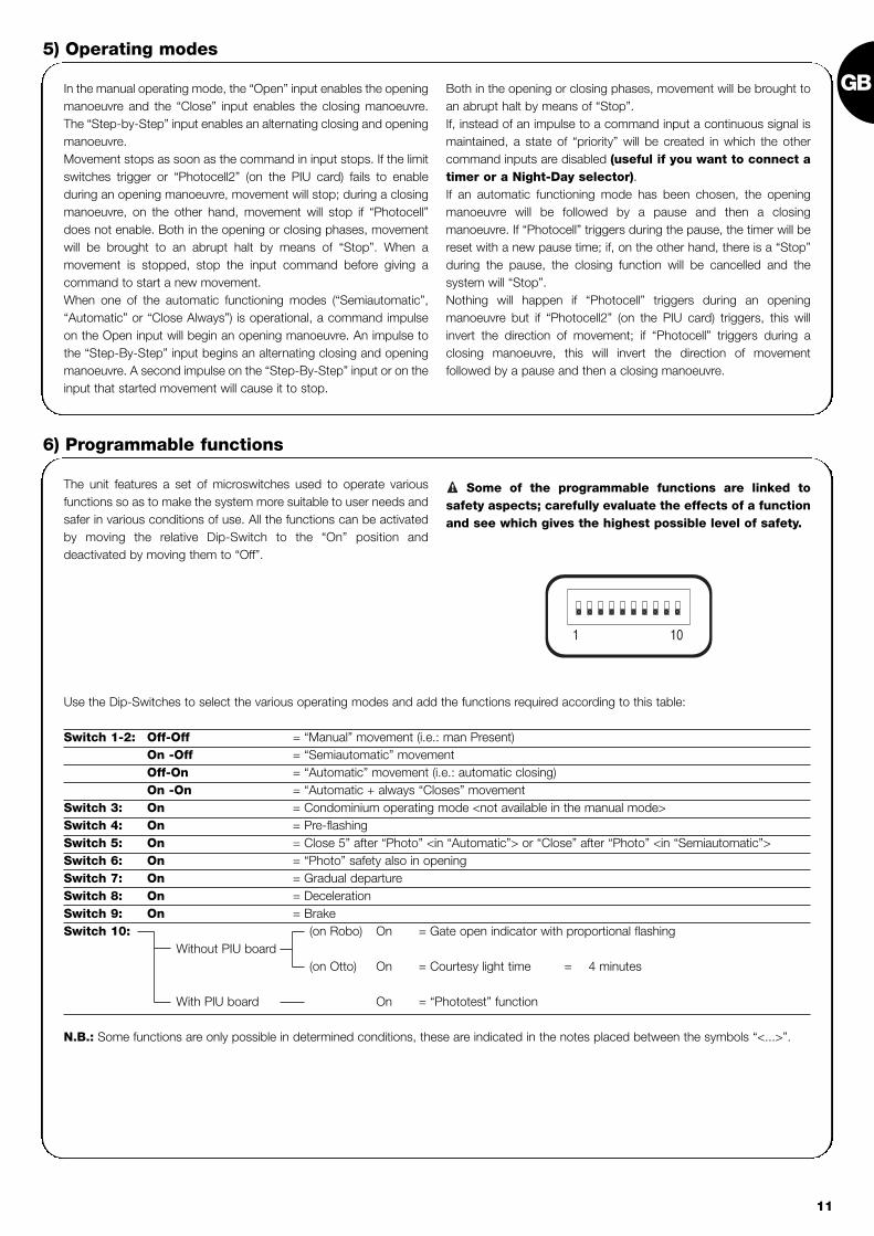
The unit features a set of microswitches used to operate variousfunctions so as to make the system more suitable to user needs andsafer in various conditions of use. All the functions can be activatedby moving the relative Dip-Switch to the “On” position anddeactivated by moving them to “Off”.
Some of the programmable functions are linked tosafety aspects; carefully evaluate the effects of a functionand see which gives the highest possible level of safety.
!
Use the Dip-Switches to select the various operating modes and add the functions required according to this table:
Switch 1-2: Off-Off = “Manual” movement (i.e.: man Present)On -Off = “Semiautomatic” movementOff-On = “Automatic” movement (i.e.: automatic closing)On -On = “Automatic + always “Closes” movement
Switch 3: On = Condominium operating mode <not available in the manual mode>Switch 4: On = Pre-flashingSwitch 5: On = Close 5” after “Photo” <in “Automatic”> or “Close” after “Photo” <in “Semiautomatic”>Switch 6: On = “Photo” safety also in openingSwitch 7: On = Gradual departureSwitch 8: On = DecelerationSwitch 9: On = BrakeSwitch 10: (on Robo) On = Gate open indicator with proportional flashing
Without PIU board(on Otto) On = Courtesy light time = 4 minutes
With PIU board On = “Phototest” function
N.B.: Some functions are only possible in determined conditions, these are indicated in the notes placed between the symbols “<...>”.
6) Programmable functions
101
12
6.1) Description of functionsHere is a brief description of the functions that can be added by moving the relative Dip-Switch to “ON”.
Switch 1-2: Off-Off = “Manual” movement (man present)On-Off = “Semiautomatic” movementOff-On = “Automatic” movement (automatic closing)On-On = “Automatic + Always Closes” movement
In the “Manual” operating mode, the gate will only move as long as the relative control button is held down.In the “Semiautomatic” operating mode a command impulse will perform the whole movement until the Working Time limit expires or themechanical stop is reached. In the “Automatic” operating mode, an opening manoeuvre is followed by a pause and then an automatic closingmanoeuvre.The “Always Closes” function comes into play following a power failure; if the gate is open, a closing manoeuvre takes place, automaticallypreceded by 5 seconds of pre-flashing.
Switch 3: On = Condominium operating mode (not available in the Manual mode)In the Condominium operating mode, once an opening manoeuvre has started it cannot be interrupted by other command pulses on “Step-by-Step” or “Open” until the gate has finished opening.During a closing manoeuvre, a new command pulse will stop the gate and reverse the direction of movement in order to open the gate.
Switch 4: On = Pre-flashingA command impulse activates the flashing lamp followed by movement 5 s later (2 s later in the manual mode).
Switch 5: On = “Close” 5 s after “Photo” <in the “Automatic” mode> or “Close” after “Photo” <in the “Semiautomatic” mode>This function, if in the “Automatic” mode, allows the gate to be kept open only for the time required for transit; when “Photo” finishes, themanoeuvre stops. After 5 s a closing manoeuvre will automatically begin. If “Photo” triggers in the “Semiautomatic” mode during a closingmanoeuvre the “Automatic” closing manoeuvre is activated with the adjusted pause time.
Switch 6: On = Safety “Photo” also during the opening manoeuvreThe “Photo” safety device is normally just active during the closing manoeuvre; if Dip-Switch 6 is turned "On" the safety device will also triggerduring the opening manoeuvre.In the “Semiautomatic” or “Automatic” modes, the opening manoeuvre will start again immediately after the photocell has been disengaged.
Switch 7: On = Gradual departureStarts the manoeuvre gradually, preventing the automatic system from being jolted.
Switch 8: On = DecelerationDeceleration reduces speed to 30% of rated speed in order to prevent unnecessary jolts at the end of a manoeuvre.
As well as reducing the speed of the manoeuvre, the deceleration function also reduces motor torque by 70%.
For systems requiring elevated torque, this decrease may cause the motor to stop immediately.
ROBO – THOR version:Following the opening or closing manoeuvre which takes place atthe end of the Working Time. A deceleration phase lasting as theWorking Time (TL) is carried out .If the manoeuvre is terminated by the limit switches and thedeceleration phase is not performed, adjust Working Time so thatdeceleration begins 30-50 cm before the limit switches cut in.
OTTO version:Following the closing manoeuvre the deceleration phase lasts 3 s iftriggered by the limit switches and as match as the Working Time(the deceleration function works better with the limit switches).During the opening manoeuvre a gradual stopping function is usedinstead of the deceleration feature.
If the deceleration function is used on sensitiveinstallations and if this lasts more than 3 s, install a mainsfilter of at least 6A with attenuation of 30dB on the mains
! power terminals near the control unit in order not toexceed the limits of electromagnetic emission specified inthe EN 50081-1 standard.

GB
13
Switch 9: On = BrakeAt the end of the movement a motor brake procedure is performed, initially slight and then more incisive in order to stop the gate rapidly butwithout jolts.
This function controls photocell efficiency at the beginning of each manoeuvre. See the “Phototest” chapter.
To create an automation system working with 2 opposed leafs:• Use two motors with the control units connected as indicated in
fig. 5.• Connect the flashing light and the “Gate Open Indicator” to any
one of the two control units .• The inputs must be connected in parallel. • The “Common” of the inputs can be connected to one of the 2
control units.
• Connect the 0Volts (Terminal 5) of the two control units.• The “Phototest” function must not be used• The “Condominium” function ( Dip-Switch 3) should be fitted as
this allows the leafs to be resynchronised if the 2 control unitsbecome unsynchronised.
7) Using 2 control units on opposed leafs
444342411210 11 1386 75 9431 2
24 V
200m
A
CO
M
SC
A
CLOS
EOP
ENSTE
P-BY-S
TEP
4442 431311 12 41
FCC PH
OTO
CLOS
EOP
ENSTE
P-BY-S
TEPPH
OTO
FCA
FCC
FCA
97 85 6 1042 31
CLO
SE
ST
EP
-BY-
ST
EP
OP
EN
STO
P
CO
M
SC
A
200m
A24
V
PH
OTOFLA
SH
ING
LIG
HT
PO
WE
RIN
PU
T
FLAS
HING
LIG
HT
PO
WE
RIN
PU
T
Switch 10: On
ROBO - THOR
Without the PIU board fitted:• Gate open indicator with proportional flashing
With the PIU board fitted:• “Phototest”
OTTO
Without the PIU board fitted:• Courtesy light time = 4 minutes
With the PIU board fitted:• “Phototest”
5

14
“PIU” CardThe control unit is already fitted with all the functions used in a normal installation. In order to allow the system to be used in special instal-lations, an optional card called “PIU” has been produced which adds new functions such as traffic light signalling, courtesy light, electriclocking, “Photocell2”, partial opening and “Phototest”.
Red = Red traffic lightThis is normally always off and switches on whenthe gate moves.
Green = Green traffic lightThis is normally on and switches off when thegate moves
Electric lock = Output for electric lock command.The electric lock is activated for 1.5 s. at the startof the opening movement.
Courtesy light/ Phototest = Output that if used to control the courtesy light,
turns on a courtesy light at the beginning of eachmovement which remains on after the movementhas finished for a time programmed with theT.Cor. trimmer on the “PIU” board.If the “Phototest” function is activated (Dip-Switch 10 = ON) this output allows thephotocells to be tested at the beginning of eachmanoeuvre.
Partial open = Input for partial opening (Partial Open, Stop,Close, Stop). This performs the same function asthe “Step-by-Step” on the main board, with thedifference that the open manoeuvre lasts for thetime set up on the T.AP.P. trimmer on the “PIU”board.
Photo 2 = 2nd safety device input. This safety device cutsin just during the opening manoeuvre causingthe gate to stop and eventually close if a“Semiautomatic” or “Automatic” operation modeis programmed on the control unit.
24 V = 24V output used to power services such asphotocells or the like. Terminal 11 is also thecommon for the inputs.
“RADIO” CardThe control unit features a connector for plugging in a radio card, produced by Nice, which activates the “Step-by-Step” input and allowsthe control unit to be remote-controlled with a transmitter.
8) Accessories
The control unit, being electronic, needs no particular maintenance.However, periodically make sure (at least once every six months) thatthe device adjusting motor force is in perfect working order; adjustwith the trimmer if necessary.
Carry out the whole test phase again to check that the limit switches,safety devices (photocells, pneumatic edges, etc.) and the flashinglight are in perfect working order.
9) Maintenance
This product is made from various kinds of material, some of whichcan be recycled.Make sure you recycle or dispose of the product in compliance withcurrent laws and bye-laws.
Some electric components may contain pollutingsubstances; do not dump them.!
10) Disposal
GB
15
This section will help fitters to solve some of the most commonproblems that may arise during installation.
No LED is on:• Check whether the control unit is powered (check mains voltage
is present at terminals 1-2 and a voltage of approx. 24Vac atterminals 5-6).
• Check the 2 mains fuses have not blown; if none of the Led’s ison a serious fault has probably occurred and the control unitshould therefore be replaced.
The OK LED flashes regularly but the INPUT Led’s do notreflect the state of the respective inputs• Carefully check the connections on input terminals 7-13.
The manoeuvre does not start• Check that the Led’s of the “Stop” (FCA + FCC), “Photo” and
“Photo2”, if installed, safety device are on and that the relativecommand Led that is activated (“Step-By-Step”, “Open” or“Close”) remains on for the whole duration of the command.
The gate changes direction during a manoeuvreAn inversion is caused by:• The photocells triggering (“Photo2” during the opening
manoeuvre, or “Photo” during the closing manoeuvre); in thiscase, check the connections of the photocells and check theinput Led’s.
11) What to do if .…
Mains power input : 230 Vac 50/60 HzVersions /V1 : 120 Vac 50/60 Hz
Max. current for 24V services : 200mAFlashing lamp output : For flashing lamps at mains voltage, maximum power 40 WGate open indicator output “SCA” : For indicator lamps at 24 Vac, maximum power 2 WOperating temperature : -20 ÷ 70 °CWorking Time on ROBO/THOR : Adjustable from 2.5 to >60 s, or from <50 a to >120 s with TLMWorking Time on OTTO : Adjustable from 2.5 to >20 s, or from <20 to >40 s with TLMPause Time : Adjustable from 5 to > 160 s.
On the PIU cardPartial opening time ROBO/THOR : Adjustable from 1 to > 30 s.Partial opening time OTTO : Adjustable from 1 to > 14 s.Courtesy light time : Adjustable from 1 to > 180 s.
12) Technical specifications

16
centrale comando motoriduttorirobo, thor, otto
Avvertenze:
Il presente manuale è destinato solamente al personaletecnico qualificato per l'installazione. Nessuna informazionecontenuta nel presente fascicolo può essere consideratad’interesse per l'utilizzatore finale!Questo manuale è riferito solo a questa centrale e non deveessere utilizzato per prodotti diversi.Si consiglia di leggere attentamente tutte le istruzioni, almeno unavolta, prima di procedere con l’installazione.
!
Indice: pag.
1 Descrizione del prodotto 17
2 Installazione 182.1 Impianto tipico 182.2 Collegamenti elettrici 182.2.1 Schema elettrico 192.2.2 Descrizione dei collegamenti 192.2.3 Fototest 202.2.4 Verifica dei collegamenti 21
3 Regolazioni 21
4 Collaudo 22
5 Modi di funzionamento 23
pag.
6 Funzioni programmabili 236.1 Descrizione delle funzioni 24
7 Utilizzo di 2 centrali su ante contrapposte 25
8 Accessori Opzionali 26
9 Manutenzione 26
10 Smaltimento 26
11 Cosa fare se… 27
12 Caratteristiche tecniche 27

I
17
1) Descrizione del prodotto:Questa centrale per l’automazione di cancelli e porte automatiche,permette di comandare i motoriduttori ROBO, THOR, OTTO, incorrente alternata monofase.A seconda del tipo di motoriduttore da comandare, la centralepresenta delle differenze, quali ad esempio: “Regolazione di Forza”,“Spia Cancello Aperto” e “Luce di Cortesia”.Sono presenti inoltre una serie di funzioni selezionabili tramite deiDip-Switch (mini selettori) e delle regolazioni effettuabili con deiTrimmer.
Dei Led posti vicino agli ingressi ne segnalano lo stato; un ulterioreLed presente vicino al microprocessore, segnala il correttofunzionamento della logica interna.
Per facilitare il riconoscimento delle parti, in fig.1 sono indicati icomponenti più significativi.
Codice Prodotto* Codice Centrale di Comando* Funzione Aggiuntiva
ROBORO1000RO1020
ROA3 Trimmer di “Regolazione Forza”
RO1010 ROA4 Relè “Spunto”
THOR TH1551 THA5 Trimmer di “Regolazione Forza”TH2251 THA6 Relè “Spunto”
OTTO OT21 OTA1 Uscita “Luce di Cortesia”
* = aggiungere al codice V1 per versione a 120 V 50/60 Hz
LMNOP
J
QRST
V U
I
X
W
YHG
FZ
EDCBA
CH
P.P.
AP
FOTO
FCA
FCCOK
Dip-Switch di selezione delle funzioniTrimmer di “Regolazione Forza”Trimmer di regolazione Tempo Lavoro (TL)Trimmer di regolazione Tempo Pausa (TP)Morsettiera per Antenna e 2° canaleInnesto scheda RADIOLed di segnalazione stato ingressiMorsettiera Ingressi / Uscite di comandoRelè “Comune”Morsettiera alimentazione / LampeggianteConnettore primario trasformatoreFusibile di linea (5A)Connettore uscita “Luce di Cortesia” (solo su OTTO)Uscita alimentazione motoreConnettore innesto condensatoreRelè “Spunto”Triac “Luce di Cortesia” (solo su OTTO)Triac “Chiude”Triac “Apre”Connettore secondario trasformatoreIngresso finecorsa FCA / FCCFusibile di bassa tensione (500mA)Innesto scheda PIULed OKMicroprocessore
ABCDEFGHIJLMNOPQRSTUVWXYZ
1

18
2.1) Impianto tipico
Per chiarire alcuni termini ed alcuni aspetti di un impianto di automazione per porte o cancelli, riportiamo un esempio tipico.
ROBO e THOR OTTO
1) Coppia fotocellule “Foto”2) Lampeggiante3) Selettore a chiave4) Costa pneumatica5) Coppia fotocellule “Foto 2”
In particolare ricordiamo che:• Tutte le fotocellule prodotte da Nice dispongono del sistema di sincronismo che permette di eliminare il problema dell’interferenza
tra due coppie di fotocellule (per altri particolari vedere le istruzioni delle fotocellule)• La coppia di fotocellule “Foto” in apertura non ha effetto mentre provoca una inversione durante la chiusura.• La coppia di fotocellule “Foto2” in chiusura non ha effetto mentre provoca una inversione durante l’apertura.
2.2) Collegamenti elettrici
Per garantire l'incolumità dell'operatore e per preveniredanni ai componenti, mentre si effettuano i collegamenti osi innestano le varie schede la centrale deve essereassolutamente spenta.
• Alimentare la centrale attraverso un cavo da 3 x 1,5mm2. Se ladistanza fra la centrale e la connessione all'impianto di terrasupera i 30m è necessario prevedere un dispersore di terra inprossimità della centrale.
• Nei collegamenti della parte a bassissima tensione di sicurezzausare cavetti di sezione minima pari a 0,25mm2.
• Usare cavetti schermati se la lunghezza supera i 30m collegandola calza a terra solo dal lato della centrale.
• Evitare di fare connessioni ai cavi in casse interrate anche secompletamente stagne.
• Gli ingressi dei contatti di tipo Normalmente Chiuso (NC), se nonusati, vanno ponticellati con “comune 24V” esclusi gli ingressidelle fotocellule nel caso sia inserita la funzione di “Fototest”. Perulteriori chiarimenti vedere paragrafo “Fototest”.
• Se per lo stesso ingresso ci sono più contatti (NC) vanno posti inserie tra di loro.
• Gli ingressi dei contatti di tipo Normalmente Aperto (NA) se nonusati vanno lasciati liberi.
• Se per lo stesso ingresso ci sono più contatti (NA) vanno posti inparallelo tra di loro.
• I contatti devono essere assolutamente di tipo meccanico esvincolati da qualsiasi potenziale, non sono ammessicollegamenti a stadi tipo quelli definiti "PNP", "NPN", "OpenCollector" ecc.
!
Ricordiamo che gli impianti di cancelli e porte automatichedevono essere installati solo da personale tecnico qualificato e
nel pieno rispetto delle norme di legge. Seguire attentamentele indicazioni del fascicolo : “Avvertenze per l’installatore”.
!
2) Installazione:
2a 2b
FOTO
FOTO
FOTO 2
5
3
2
1
3
4
FOTO
21

I
19
2.2.1) Schema elettrico
2.2.2) Descrizione dei collegamenti
Riportiamo una breve descrizione dei possibili collegamenti della centrale verso l’esterno.
Morsetti Funzione Descrizione
1-2 : Alimentazione = Linea di alimentazione da rete
3-4 : Lampeggiante = Uscita per collegamento del lampeggiante a tensione di rete ( Max. 40W)
5-6 : 24 Vac = Alimentazione servizi 24Vac (Foto, Radio, ecc.) Max 200mA
7 : Comune = Comune per tutti gli ingressi
8 : Spia C.A. (SCA) = “Spia Cancello Aperto” 24Vac max. 2W ( Non presente su versione OTTO)
9 : Alt = Ingresso con funzione di arresto della manovra con breve inversione del moto
10 : Foto = Ingresso per dispositivi di sicurezza (fotocellule, coste pneumatiche)
11 : Passo-Passo (PP) = Ingresso per movimento ciclico (“Apre” - “Stop” - “Chiude” - “Stop”)
12 : Apre = Ingresso per movimento in apertura
13 : Chiude = Ingresso per movimento in chiusura
41-42 : 2° Ch Radio = Uscita dell’eventuale secondo canale del ricevitore radio
43-44 : Antenna = Ingresso per antenna del ricevitore radio
3

20
2.2.3) Fototest
Il “Fototest”, aumenta l’affidabilità dei dispositivi di sicurezza;permettendo di raggiungere la “categoria 2” secondo la norma UNIEN 954-1 (ediz. 12/1998) per quanto riguarda l’insieme centrale efotocellule di sicurezza.Ogni volta che viene avviata una manovra vengono controllati idispositivi di sicurezza coinvolti; solo se tutto è a posto la manovraha inizio. Se invece il test non dà esito positivo (fotocellula accecatadal sole, cavi in corto circuito, ecc.) viene individuato il guasto e lamanovra non viene eseguita.
Per ottenere la funzione “Fototest” è necessario:• Utilizzare la scheda aggiuntiva PIU.• Impostare il Dip-Switch 10 ON • Realizzare una particolare configurazione nei collegamenti dei
dispositivi di sicurezza come in fig.4a che prevede di collegarel’alimentazione dei trasmettitori delle fotocellule non direttamentedall’uscita dei servizi, ma interrompendo tale alimentazionepassando per i morsetti 7 e 8 della scheda PIU. La correntemassima utilizzabile sull’uscita “Fototest” della scheda PIU è di100mA (2 coppie di fotocellule Nice)
• Alimentare i ricevitori direttamente dall’uscita servizi dellacentrale (morsetti 5-6).
Se in un secondo momento non si desiderasse più utilizzare la funzione
di Fototest, sarà necessario abbassare il Dip-Switch 10 e modificare la
configurazione dei collegamenti come indicato nella fig.4b.
Il test delle fotocellule avviene in questo modo: quando è richiesto unmovimento, in primo luogo viene controllato che tutti i ricevitoriinteressati dal movimento diano il consenso, poi viene spental’alimentazione ai trasmettitori e quindi verificato che tutti i ricevitorisegnalino il fatto togliendo il loro consenso; infine viene riattivatal'alimentazione dei trasmettitori e quindi nuovamente verificato ilconsenso da parte di tutti i ricevitori. Solo se questa sequenza haesito positivo, la manovra verrà avviata.È sempre bene inoltre attivare il sincronismo attraverso il taglio degliappositi ponticelli sui trasmettitori; questo è l'unico metodo pergarantire che due coppie di fotocellule non interferiscano tra loro.Verificare sul manuale delle fotocellule le istruzioni per ilfunzionamento sincronizzato.
Nel caso un ingresso sottoposto a “Fototest” non venga utilizzato(Esempio “Foto2”) e si desideri comunque la funzione fototestoccorre ponticellare l’ingresso non usato come indicato in fig.4c.
139 10765 8(Scheda PIU)
9 8101112 7
78911 1012
(Scheda PIU) 139 10765 8
1098 13765
7
10
PIU
PIU8
11
PIU
PIU
PIU 8
RX
43 51 2
6
FOTO
5107
RX
543
FOTO 2
21
65
(scheda PIU)
7
RX
54321
6
FOTO
RX
107
(scheda PIU)FOTO 2
5
10PIU6
7
531 2 4
5
RX
3 4 51 2
6
107
5
FOTO
10PIU
PIU 11
RX
1 2
712
PIUPIU
21
3 4 51 2
RX
53 41 2
8 7
TX
1012 11 9
(Scheda PIU)
1 2
TX
21
FOTO 2
FOTO
(scheda PIU)
7PIU
21
RX
42 3 5
65
56
21
RX
2 3 4 5
TX
FOTO
21
TX
(scheda PIU)FOTO 2
1 2
1
1
1 2
712
PIUPIU
RX
3 4 51 2
TX
1 2
FOTO
12PIU
TX
TX
TX
TX
TX
“Foto” e “Foto2” con “Fototest”
“Foto” e “Foto2” senza “Fototest”
“Foto” con “Fototest”
4a
4b
4c

I
21
2.2.4) Verifica dei collegamenti
Le prossime operazioni vi porteranno ad agire su circuiti sottotensione. La maggior parte dei circuiti sono sottoposti a bassissimatensione di sicurezza e quindi non pericolosa, alcune parti sonosottoposte a tensione di rete quindi ALTAMENTE PERICOLOSE!Prestate la massima attenzione a ciò che fate e NON OPERATEMAI DA SOLI!
• Alimentare la centrale e subito verificare che tra i morsetti 5-6 visiano circa 24Vac.
• Verificare che, dopo pochi istanti di lampeggio veloce, il Led“OK” lampeggi ad una cadenza regolare.
• Ora verificare che i Led relativi agli ingressi con contatti tipo (NC) sianoaccesi (tutte le sicurezze attive) e che i Led relativi ad ingressi tipo (NA)siano spenti (nessun comando presente). Se questo non avvienecontrollare i collegamenti e l’efficienza dei vari dispositivi. L’ingresso di“Alt” interviene spegnendo sia il finecorsa FCA che FCC.
• Verificare l’esatto collegamento dei finecorsa; muovere la leva delfinecorsa e verificare che il relativo finecorsa intervengaspegnendo il corrispondente led sulla centrale.
• Sbloccare l’anta e portarla a metà della corsa, poi bloccare. Inquesto modo l’anta è libera di muoversi sia in apertura che inchiusura.
• Ora bisognerà verificare se il movimento avviene nella direzionecorretta, cioè controllare la corrispondenza tra il movimentoprevisto dalla centrale e quello effettivo delle ante. Questa verifica èfondamentale, se la direzione è sbagliata in alcuni casi (ad esempioin modo “Semiautomatico”) l’automatismo potrebbe in apparenza
funzionare regolarmente, infatti il ciclo “Apre” è simile al ciclo“Chiude”, con la fondamentale differenza che i dispositivi disicurezza verranno ignorati nella manovra di “Chiude”, chenormalmente è la più pericolosa, ed interverranno in aperturaprovocando una richiusura addosso all’ostacolo con effettidisastrosi!
• Per verificare che il senso di rotazione sia esatto è sufficientedare un breve impulso sull’ingresso PP; la prima manovra che lacentrale esegue dopo essere stata alimentata è sempre “Apre”,quindi è sufficiente verificare che l’automatismo si muova nelsenso dell’apertura. Nel caso il movimento sia avvenuto in sensoerrato occorre:
� Spegnere alimentazione� Ruotare di 180° il connettore di alimentazione del motore
e quello dei finecorsa. (Rif. “O” e rif. “V” di fig.1)� Eseguito quanto descritto, riprovare se il senso di rotazione
è corretto ripetendo l’ultimo punto.
Il Led “OK” posizionato al centro della scheda, ha il compito di
segnalare lo stato della logica interna: un lampeggio regolare ed alla cadenza
di 1 secondo indica che il microprocessore interno è attivo ed è in attesa di
comandi. Quando invece lo stesso microprocessore riconosce una variazione
dello stato di un ingresso (sia ingresso di comando che Dip-Switch delle
funzioni) genera un doppio lampeggio veloce, questo anche se la variazione
non provoca effetti immediati. Un lampeggio molto veloce per 3s. indica che
la centrale è appena stata alimentata e sta eseguendo un test delle parti
interne; infine un lampeggio non costante indica che il test non è andato a
buon fine e quindi c’è un guasto.
!
Le regolazioni sono effettuabili attraverso dei Trimmer che agisconomodificando i seguenti parametri:
Tempo Lavoro (TL): Regola la durata massima della manovra di apertura o chiusura.
Per la regolazione del TL, selezionare il modo di funzionamento“Semiautomatico” ponendo in ON il Dip-Switch 1 quindi regolare ilTrimmer TL a metà corsa. Con queste regolazioni eseguire un ciclodi apertura e di chiusura ed eventualmente intervenire sullaregolazione del Trimmer TL in modo tale che sia sufficiente adeseguire tutta la manovra e rimanga ancora un margine di 2s. o 3s.Nel caso in cui anche ponendo il Trimmer TL al massimo non siottenga un tempo sufficiente, tagliare il ponticello TLM, posto sullostampato tra i Trimmer TL e TP, in modo da ottenere un TempoLavoro Maggiorato (TLM).
Tempo Pausa (TP):Nel funzionamento “Automatico” regola il tempo tra il termine dellamanovra di apertura e l’inizio della manovra di chiusura.
Per la regolazione del TP, selezionare il modo di funzionamento“Automatico” spostando in ON il Dip-Switch 2, quindi regolare ilTrimmer TP a piacere. Per la verifica occorre eseguire una manovradi apertura, quindi controllare il tempo che trascorre prima dellarichiusura “Automatica”.
Forza (F): Presente sulla centrale di comando per permette di regolare il valoredella “Forza” massima.
Particolare attenzione deve essere posta nella regolazione delTrimmer “Forza”, perché questa regolazione può influire sul grado disicurezza dell’automazione. Per la regolazione occorre procedereper tentativi successivi misurando la forza applicata dall’anta ecomparandola con quanto previsto dalle normative.Nelle centrali per RO1010 e OT21 la “Forza” viene regolataattraverso un selettore a più posizioni posto sul contenitore deltrasformatore di alimentazione della centrale.
3) Regolazioni:
TPTLF
TLM
22
Terminate le verifiche e le regolazioni è possibile passare al collaudo dell’impianto.
Il collaudo dell’automazione deve essere eseguito da personale qualificato ed esperto che dovrà farsi carico distabilire le prove previste in funzione del rischio presente.
Il collaudo è la parte più importante di tutta la realizzazione dell’automazione. Ogni singolo componente, ad esempio motoriduttore, arrestodi emergenza, fotocellule ecc. può richiedere una specifica fase di collaudo e per questo si consiglia di seguire le procedure riportate neirispettivi manuali di istruzioni.
Per il collaudo della centrale eseguire la seguente sequenza di operazioni:
1. Selezione funzioni: • Impostare ON il Dip-Switch 1 (Funzionamento “Semiautomatico”)• Se si sono realizzati i collegamenti di fig.4a per l’utilizzo della funzione di “Fototest” (se presente scheda PIU), impostare ON il Dip-Switch 10 (Funzione “Fototest”).• Impostare OFF tutti gli altri Dip-Switch
2. Premere e il tasto di comando “Apre” oppure “Passo-Passo” e verificare che:• si attivi il lampeggiante• inizi una manovra di apertura • il movimento si arresti, al raggiungimento del finecorsa di apertura FCA.
3. Premere il tasto di comando “Chiude” oppure “Passo-Passo” e verificare che:• si attivi il lampeggiante• parta una manovra di chiusura• il movimento si arresti, al raggiungimento del finecorsa di chiusura FCC
4. Far partire una manovra di apertura e verificare che durante la manovra l’intervento di un dispositivo:• Collegato all’ingresso “Alt”, provochi l’arresto con breve inversione del moto• Collegato all’ingresso “Foto”, non abbia nessun effetto • Collegato all’ingresso “Foto2”, provochi la fermata e l’inversione della manovra (se presente scheda PIU)
5. Far partire una manovra di chiusura e verificare che durante la manovra l’intervento di un dispositivo:• Collegato all’ingresso “Alt”, provochi l’arresto con breve inversione del moto• Collegato all’ingresso “Foto”, provochi la fermata e l’inversione della manovra• Collegato all’ingresso “Foto2”, non abbia nessun effetto (se presente scheda PIU)
6. Sugli ingressi collegati, verificare che l’attivazione dell’ingresso provochi un passo nella sequenza:• Ingresso “Passo-Passo”: Sequenza = “Apre” – “Stop” – “Chiude” – ”Stop”• Ingresso “Apre”: Sequenza = “Apre” – “Stop” – “Apre” – “Stop”• Ingresso “Chiude”: Sequenza = “Chiude” – “Stop” - “Chiude” – “Stop”• Ingresso “Apre Parziale”: Sequenza = “Apre Parziale” – “Stop” – “Chiude” – “Stop” (se presente scheda PIU).
7 Se si utilizza la funzione “Fototest” verificare l’efficienza del test (se presente scheda PIU):• Interrompere la fotocellula “Foto”, quindi far partire una manovra e verificare che questa non venga eseguita • Interrompere la fotocellula “Foto2”, quindi far partire una manovra e verificare che questa non venga eseguita• Cortocircuitare il contatto della fotocellula “Foto”, quindi far partire una manovra e verificare che questa non venga eseguita • Cortocircuitare il contatto della fotocellula “Foto2”, quindi far partire una manovra e verificare che questa non venga eseguita
8. Eseguire le prove per la rilevazione delle “Forze” di Impatto come previsto della EN 12445.
Se al termine del collaudo vengono attivate ulteriori funzioni programmabili che possono ridurre la sicurezza dell’impianto, è necessarioeffettuare un collaudo specifico di tali funzioni.
!
4) Collaudo

I
23
5) Modi di funzionamento
Nel funzionamento in modo manuale, l’ingresso “Apre” consente ilmovimento in apertura, l’ingresso “Chiude” consente il movimento inchiusura. Il “Passo-Passo” consente il movimento alternativamentein apertura e in chiusura. Non appena cessa il comando in ingresso, il movimento si arresta.In apertura il movimento si arresta quando intervengono i finecorsaoppure se manca il consenso dalla “Foto2” (su scheda PIU); inchiusura invece il movimento si arresta se manca il consenso di“Foto”. Sia in apertura che in chiusura un intervento su “Alt” provocasempre un immediato arresto del movimento. Una volta che unmovimento si è arrestato è necessario far cessare il comando iningresso prima che un nuovo comando possa far iniziare un nuovomovimento.Nel funzionamento in uno dei modi automatici (“Semiautomatico”,“Automatico” o “Chiude Sempre”) un impulso di comandosull’ingresso “Apre” provoca il movimento in apertura. Un impulso su“Passo-Passo” provoca alternativamente apertura o chiusura. Unsecondo impulso sul “Passo-Passo” o sullo stesso ingresso che ha
iniziato il movimento provoca uno “Stop”.Sia in apertura che in chiusura un intervento su “Alt” provoca unimmediato arresto del movimento.Se in un ingresso di comando invece di un impulso viene mantenutoun segnale continuo si provoca uno stato di “prevalenza” in cui glialtri ingressi di comando rimangono disabilitati (utile per collegareun orologio o un selettore Notte-Giorno).Nel caso fosse selezionato il modo di funzionamento automatico,dopo una manovra di apertura, viene eseguita una pausa, al termine,viene eseguita una chiusura. Se durante la pausa vi fosse unintervento di “Foto”, il temporizzatore verrà ripristinato con un nuovoTempo Pausa; se invece durante la pausa si interviene su “Alt” lafunzione di richiusura viene cancellata e si passa in uno stato di“Stop”.In apertura l’intervento di “Foto” non ha alcun effetto mentre la“Foto2” (su scheda PIU) provoca l’inversione del moto; in chiusural’intervento di “Foto” provoca una inversione del moto, poi unapausa, quindi una richiusura.
La centrale dispone di una serie di microinterruttori che permettonodi attivare varie funzioni al fine di rendere l’impianto più adatto alleesigenze dell’utilizzatore e più sicuro nelle varie condizioni d’uso. Lefunzioni si attivano ponendo il relativo dip-switch in posizione “On”mentre non sono inserite con il corrispondente Dip-Switch in “Off”.
Alcune delle funzioni programmabili sono legate adaspetti della sicurezza. Valutare con molta attenzione glieffetti di ogni funzione, verificando quale sia quella chedia la maggior sicurezza possibile.
!
I Dip-Switch permettono di selezionare i vari modi di funzionamento e di inserire le funzioni desiderate secondo la seguente tabella:
Switch 1-2: Off-Off = Movimento “Manuale” cioè uomo presenteOn -Off = Movimento “Semiautomatico”Off-On = Movimento “Automatico” cioè chiusura automaticaOn -On = Movimento “Automatico” + Chiude Sempre
Switch 3: On = Funzionamento Condominiale < non disponibile in modo manuale >Switch 4: On = PrelampeggioSwitch 5: On = Richiudi 5 s. dopo “Foto” < se in “Automatico” > o Chiudi dopo Foto < se in “Semiautomatico” >Switch 6: On = Sicurezza “Foto” anche in aperturaSwitch 7: On = Partenza gradualeSwitch 8: On = RallentamentoSwitch 9: On = FrenoSwitch 10: (su Robo) On = Spia Cancello Aperto (SCA) con lampeggio proporzionale
Senza scheda PIU (su Otto) On = Tempo luce di cortesia = 4 minuti
Con scheda PIU On = Funzione “Fototest”
NOTA: Alcune funzioni sono possibili solo in determinate condizioni; queste sono segnalate con le note tra i caratteri “<...>”.
6) Funzioni programmabili
101
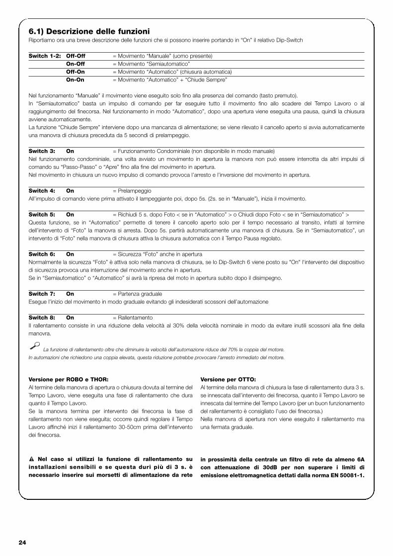
24
6.1) Descrizione delle funzioniRiportiamo ora una breve descrizione delle funzioni che si possono inserire portando in “On” il relativo Dip-Switch
Switch 1-2: Off-Off = Movimento “Manuale” (uomo presente)On-Off = Movimento “Semiautomatico”Off-On = Movimento “Automatico” (chiusura automatica)On-On = Movimento “Automatico” + “Chiude Sempre”
Nel funzionamento “Manuale” il movimento viene eseguito solo fino alla presenza del comando (tasto premuto).In “Semiautomatico” basta un impulso di comando per far eseguire tutto il movimento fino allo scadere del Tempo Lavoro o alraggiungimento del finecorsa. Nel funzionamento in modo “Automatico”, dopo una apertura viene eseguita una pausa, quindi la chiusuraavviene automaticamente.La funzione “Chiude Sempre” interviene dopo una mancanza di alimentazione; se viene rilevato il cancello aperto si avvia automaticamenteuna manovra di chiusura preceduta da 5 secondi di prelampeggio.
Switch 3: On = Funzionamento Condominiale (non disponibile in modo manuale)Nel funzionamento condominiale, una volta avviato un movimento in apertura la manovra non può essere interrotta da altri impulsi dicomando su “Passo-Passo” o “Apre” fino alla fine del movimento in apertura.Nel movimento in chiusura un nuovo impulso di comando provoca l’arresto e l’inversione del movimento in apertura.
Switch 4: On = PrelampeggioAll’impulso di comando viene prima attivato il lampeggiante poi, dopo 5s. (2s. se in “Manuale”), inizia il movimento.
Switch 5: On = Richiudi 5 s. dopo Foto < se in “Automatico” > o Chiudi dopo Foto < se in “Semiautomatico” >Questa funzione, se in “Automatico” permette di tenere il cancello aperto solo per il tempo necessario al transito, infatti al terminedell’intervento di “Foto” la manovra si arresta. Dopo 5s. partirà automaticamente una manovra di chiusura. Se in “Semiautomatico”, unintervento di “Foto” nella manovra di chiusura attiva la chiusura automatica con il Tempo Pausa regolato.
Switch 6: On = Sicurezza “Foto” anche in aperturaNormalmente la sicurezza “Foto” è attiva solo nella manovra di chiusura, se lo Dip-Switch 6 viene posto su "On" l'intervento del dispositivodi sicurezza provoca una interruzione del movimento anche in apertura.Se in “Semiautomatico” o “Automatico” si avrà la ripresa del moto in apertura subito dopo il disimpegno.
Switch 7: On = Partenza gradualeEsegue l’inizio del movimento in modo graduale evitando gli indesiderati scossoni dell’automazione
Switch 8: On = Rallentamento Il rallentamento consiste in una riduzione della velocità al 30% della velocità nominale in modo da evitare inutili scossoni alla fine dellamanovra.
La funzione di rallentamento oltre che diminuire la velocità dell’automazione riduce del 70% la coppia del motore.
In automazioni che richiedono una coppia elevata, questa riduzione potrebbe provocare l’arresto immediato del motore.
Versione per ROBO e THOR:Al termine della manovra di apertura o chiusura dovuta al termine delTempo Lavoro, viene eseguita una fase di rallentamento che duraquanto il Tempo Lavoro.Se la manovra termina per intervento dei finecorsa la fase dirallentamento non viene eseguita; occorre quindi regolare il TempoLavoro affinché inizi il rallentamento 30-50cm prima dell’interventodei finecorsa.
Versione per OTTO:Al termine della manovra di chiusura la fase di rallentamento dura 3 s.se innescata dall’intervento dei finecorsa, quanto il Tempo Lavoro seinnescata dal termine del Tempo Lavoro (per un buon funzionamentodel rallentamento è consigliato l’uso dei finecorsa.)Nella manovra di apertura non viene eseguito il rallentamento mauna fermata graduale.
Nel caso si utilizzi la funzione di rallentamento suinstallazioni sensibili e se questa duri più di 3 s. ènecessario inserire sui morsetti di alimentazione da rete
! in prossimità della centrale un filtro di rete da almeno 6Acon attenuazione di 30dB per non superare i limiti diemissione elettromagnetica dettati dalla norma EN 50081-1.

I
25
Switch 9: On = FrenoAl termine del movimento viene eseguita una procedura di freno al motore, inizialmente blanda poi più incisiva in modo da fermare il cancellovelocemente ma senza scossoni.
Questa funzione permette di eseguire ad ogni inizio manovra un controllo dell’efficienza delle fotocellule. Vedere capitolo “Fototest”.
Per realizzare una automazione con 2 ante che lavorano in modocontrapposto è necessario:• Usare due motori con le centrali collegate come indicato nella
fig.5.• Collegare il lampeggiante e la “Spia Cancello Aperto” indifferen-
temente ad una delle due centrali.• Gli ingressi devono essere posti in parallelo tra loro.
• Il “Comune” degli ingressi può essere collegato ad una delle 2centrali.
• Collegare assieme i 0Volt (Morsetto 5) delle due centrali.• Non deve essere utilizzata la funzione “Fototest”.• È opportuno inserire la funzione “Condominiale” (Dip-Switch 3)
che permette di risincronizzare le ante qualora le 2 centraliperdano il sincronismo.
7) Utilizzo di due centrali su ante contrapposte
Switch 10: On
ROBO e THOR
Senza scheda PIU inserita:• “Spia Cancello Aperto” con lampeggio proporzionale
Con scheda PIU inserita:• “Fototest”
OTTO
Senza scheda PIU inserita:• Tempo “Luce di Cortesia” = 4 minuti
Con scheda PIU inserita:• “Fototest”
5

26
Scheda PIULa centrale contiene già tutte le funzioni che vengono utilizzate in una normale installazione. Per sopperire alle richieste di utilizzo inimpianti particolari, è stata predisposta una scheda opzionale PIU che permette di aggiungere nuove funzioni quali segnalazione semafori-ca, luce di cortesia, Elettroserratura, “Foto2”, apertura parziale e “Fototest”.
Rosso = Luce rossa del semaforoÈ normalmente sempre spenta, si accendedurante il movimento del cancello
Verde = Luce verde del semaforoRimane normalmente accesa, si spegne duranteil movimento del cancello
Elettroserratura = Uscita per comando elettroserratura.L'elettroserratura viene attivata per 1,5 s. all'iniziodel movimento in apertura.
Luce Cortesia/ Fototest = Uscita che se utilizzata per il comando luce di
cortesia, consente di accendere all'inizio di ognimovimento una Luce di Cortesia che rimaneaccesa oltre il termine del movimento anche peril tempo programmato con il Trimmer TempoLuce di Cortesia presente sulla scheda PIU.Se si attiva la funzione “Fototest” (Dip-Switch 10= ON) questa uscita consente di eseguire un testdelle fotocellule ad inizio manovra.
Apre parziale = Ingresso per apertura parziale (“Apre” -”Parziale”, “Stop”, “Chiude”, “Stop”). Esegue lamedesima funzione del “Passo-Passo” sullascheda principale, con la differenza che lamanovra di “Apre” dura per il tempo impostatosul Trimmer “Tempo Apertura Parziale” presentesulla scheda PIU.
Foto 2 = Ingresso 2° dispositivo di sicurezza. Questodispositivo interviene nella sola manovra diapertura provocando un arresto del movimento,con eventuale richiusura se sulla centrale èprogrammato il modo di funzionamento“Semiautomatico” o “Automatico” .
24 V = Uscita 24V utilizzabile per alimentazione iservizi come fotocellule o altro. Il morsetto 11 èanche il comune per gli ingressi .
Scheda RADIONelle centrale è predisposto un connettore per l’inserimento di una scheda radio, Nice, che permette di agire sull’ingresso di “Passo-Pas-so” e comandare in questo modo la centrale a distanza tramite un trasmettitore.
8) Accessori opzionali
La centrale come parte elettronica, non necessita di alcunamanutenzione particolare. Verificare comunque periodicamente(almeno ogni 6 mesi), la perfetta efficienza e la regolazione deldispositivo di regolazione della Forza del motore, eventualmenteagire sul trimmer di regolazione.
Rieseguire per intero la fase di collaudo per controllare la correttaefficienza dei finecorsa, dei dispositivi di sicurezza (fotocellule, costepneumatiche, ecc.) del lampeggiante.
9) Manutenzione
Questo prodotto è costituito da vari tipi di materiali, alcuni possonoessere riciclati.Informatevi sui sistemi di riciclaggio o smaltimento del prodottoattenendovi alle norme di legge vigenti a livello locale.
Alcuni componenti elettrici potrebbero conteneresostanze inquinanti, non disperdere nell’ambiente.!
10) Smaltimento

I
27
Questa vuole essere una guida per aiutare l’installatore a risolverealcuni dei più comuni problemi che si possono presentare durantel’installazione.
Nessun LED risulta acceso• Verificare se la centrale è alimentata (verificare che sui morsetti
1-2 sia presente la tensione di rete e sui morsetti 5-6 unatensione di 24Vac circa.)
• Verificare se i 2 fusibili di alimentazione sono integri: se neppure inquesto caso nessun Led risulta acceso è probabile sia presenteun guasto grave e quindi la centrale dovrà essere sostituita.
IL Led OK lampeggia regolarmente ma i led INGRESSI nonrispecchiano lo stato dei rispettivi ingressi• Verificare con attenzione i collegamenti sui morsetti degli
ingressi 7÷13.
La manovra non parte• Verificare che i Led delle sicurezze “Alt” (FCA + FCC) , “Foto”, ed
eventualmente “Foto2” siano accesi e che il Led del comandoche viene attivato (“Passo-Passo”, “Apre” o “Chiude”) si accendaper la durata del comando.
Durante il movimento il cancello effettua un’inversioneLa causa che provoca un’inversione è: • Un intervento delle fotocellule (“Foto2” in apertura, o “Foto”
durante la chiusura); controllare i collegamenti delle fotocellule edeventualmente verificare i Led di segnalazione degli ingressi.
11) Cosa fare se….
Alimentazione da rete : 230 Vac 50/60 HzVersioni /V1 : 120 Vac 50/60 Hz
Corrente Max servizi 24 V : 200mAUscita lampeggiante : Per lampeggianti a tensione di rete, potenza massima 40 WUscita spia cancello aperto “SCA” : Per lampade spia 24Vac, potenza massima 2 W Temperatura di esercizio : -20 ÷ 70 °CTempo Lavoro ROBO/THOR : Regolabile da 2.5 a > 60 s, oppure da < 50 a > 120 s con TLMTempo Lavoro OTTO : Regolabile da 2.5 a > 20 s, oppure da < 20 a > 40 s con TLMTempo Pausa : Regolabile da 5 a > 160 s.
su Scheda PIUTempo Ap. Parziale ROBO/THOR : Regolabile da 1 a > 30 s.Tempo Ap. Parziale OTTO : Regolabile da 1 a > 14 s.Tempo luce di cortesia : Regolabile da 1 a > 180 s.
12) Caratteristiche tecniche

28
armoire de commandeopérateursrobo, thor, otto
Recommandations:
Ce manuel est destiné exclusivement au personneltechnique qualifié pour l’installation. Aucune informationcontenue dans ce fascicule ne peut être considérée commeintéressante pour l’utilisateur final! Ce manuel se réfère uniquement à cette armoire decommande et ne doit pas être utilisé pour des produitsdifférents.Nous conseillons de lire attentivement toutes les instructions, au moinsune fois, avant de procéder à l’installation.
!
Table des matières: page
1 Description du produit 29
2 Installation 302.1 Installation typique 302.2 Connexions électriques 302.2.1 Schéma électrique 312.2.2 Description des connexions 312.2.3 Photo-test 322.2.4 Vérification des connexions 33
3 Réglages 33
4 Essai de fonctionnement 34
5 Modes de fonctionnement 35
page
6 Fonctions programmables 356.1 Description des fonctions 36
7 Utilisation de 2 centrales sur battants 37antagoniques
8 Accessoires en option 38
9 Maintenance 38
10 Mise au rebut 38
11 Que faire si… 39
12 Caractéristiques techniques 39
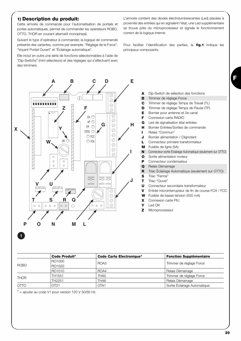
F
29
1) Description du produit:Cette armoire de commande pour l’automatisation de portails etportes automatiques, permet de commander les opérateurs ROBO,OTTO, THOR en courant alternatif monophasé.
Suivant le type d’opérateur à commander, la logique de commandeprésente des variantes, comme par exemple: “Réglage de la Force”,“Voyant Portail Ouvert” et “Éclairage automatique”.
Elle inclut en outre une série de fonctions sélectionnables à l’aide de“Dip-Switchs” (mini sélecteurs) et des réglages qui s’effectuent avecdes trimmers.
L’armoire contient des diodes électroluminescentes (Led) placées àproximité des entrées qui en signalent l’état, une Led supplémentairese trouve près du microprocesseur et signale le fonctionnementcorrect de la logique interne.
Pour faciliter l’identification des parties, la fig.1 indique lesprincipaux composants.
LMNOP
J
QRST
V U
I
X
W
YHG
FZ
EDCBA
CH
P.P.
AP
FOTO
FCA
FCCOK
Dip-Switch de sélection des fonctionsTrimmer de réglage ForceTrimmer de réglage Temps de Travail (TL)Trimmer de réglage Temps de Pause (TP)Bornier pour antenne et 2e canalConnexion carte RADIOLed de signalisation état entréesBornier Entrées/Sorties de commandeRelais “Commun”Bornier alimentation / ClignotantConnecteur primaire transformateurFusible de ligne (5A)Connecteur sortie Éclairage Automatique (seulement sur OTTO)Sortie alimentation moteurConnecteur condensateurRelais DémarrageTriac Éclairage Automatique (seulement sur OTTO)Triac “Ferme”Triac “Ouvre”Connecteur secondaire transformateurEntrée microinterrupteur de fin de course FCA / FCCFusible de basse tension (500 mA)Connexion carte PIULed OKMicroprocesseur
ABCDEFGHIJLMNOPQRSTUVWXYZ
1
Code Produit* Code Carte Electronique* Fonction Supplémentaire
ROBORO1000RO1020
ROA3 Trimmer de réglage Force
RO1010 ROA4 Relais Démarrage
THOR TH1551 THA5 Trimmer de réglage ForceTH2251 THA6 Relais Démarrage
OTTO OT21 OTA1 Sortie Éclairage Automatique
* = ajouter au code V1 pour version 120 V 50/60 Hz

30
2.1) Installation typique
Pour préciser certains termes et certains aspects d’un automatisme pour portes ou portails, nous donnons ci-après un exemple typique.
ROBO / THOR OTTO
1) Paire de photocellules “Photo”2) Clignotant3) Sélecteur à clé4) Barre palpeuse5) Paire de photocellules “Photo 2”
En particulier, nous rappelons que:• Toutes les photocellules produites par Nice disposent du système de synchronisme qui permet d’éliminer le problème de
l’interférence entre deux paires de photocellules (pour plus de détails, voir les instructions des photocellules)• La paire de photocellules “Photo” n’a pas d’effet en ouverture tandis qu’elle provoque une inversion durant la fermeture.• La paire de photocellules “Photo2” n’a pas d’effet en fermeture tandis qu’elle provoque une inversion durant l’ouverture.
Nous rappelons que les automatismes de portails et portesautomatiques doivent être installés exclusivement par dupersonnel technique qualifié et dans le plein respect des
normes légales. Suivre attentivement les recommandations dufascicule : “Recommandations pour l’installateur”.
!
2) Installation:
2a 2b
PHOTO
PHOTO
PHOTO 2
5
3
2
1
3
4
PHOTO
21
2.2) Connexions électriques
Pour garantir la sécurité de l’opérateur et pour éviterd’endommager les composants, quand on effectue lesconnexions électriques ou qu’on branche les différentescartes: l’armoire de commande doit absolument êtreéteinte.
• Alimenter l’armoire de commande avec un câble de 3 x 1,5mm2,si la distance entre l’armoire et la connexion à l’installation demise à la terre dépasse 30m, il faut prévoir une prise de terre àproximité de l’armoire de commande.
• Pour les connexions de la partie à très basse tension de sécurité,utiliser des câbles d’une section minimum de 0,25mm2.
• Utiliser des câbles blindés si la longueur dépasse 30m enmettant le blindage à la terre seulement du côté de l’armoire.
• Éviter d’effectuer des connexions de câbles dans des boîtiersenterrés même s’ils sont complètement étanches.
• Les entrées des contacts de type Normalement Fermé (NC), sielles ne sont pas utilisées, doivent être shuntés avec “commun24V” (à l’exclusion des entrées des photocellules si la fonction
de “photo-test” est insérée) pour plus de précisions voirparagraphe Photo-test.
• S’il y a plusieurs contacts NC (Normalement Fermé) pour lamême entrée, il faut les connecter en SÉRIE.
• Les entrées des contacts de type Normalement Ouvert (NA),quand elles ne sont pas utilisées, doivent être laissées libres.
• S’il y a plusieurs contacts NA (Normalement Ouvert) pour lamême entrée, il faut les connecter en parallèle.
• Les contacts doivent absolument être de type mécanique etlibres de toute puissance. Les connexions à étages type "PNP","NPN", "Open Collector", etc., ne sont pas admises.
!

F
31
2.2.1) Schéma électrique
2.2.2) Description des connexions
Nous donnons ci-après une brève description des connexions possibles de l’armoire de commande vers l’extérieur.
Bornes Fonctions Description
1-2 : Alimentation = Ligne d’alimentation de secteur
3-4 : Clignotant = Sortie pour connexion du clignotant à tension de secteur ( Max. 40W)
5-6 : 24 Vca = Alimentation services 24 Vca (Photo, Radio, etc.) Max. 200 mA
7 : Commun = Commun à toutes les entrées
8 : Voyant P.O. = Voyant portail ouvert 24 Vca max. 2W ( Non présent sur version OTTO)
9 : Halte = Entrée avec fonction d’arrêt de la manœuvre avec brève inversion du mouvement.
10 : Photo = Entrée pour dispositifs de sécurité (Photocellules, barres palpeuses)
11 : Pas-à-pas (PP) = Entrée pour mouvement cyclique (“Ouvre” - “Stop” - “Ferme” - “Stop”)
12 : Ouvre = Entrée pour mouvement en ouverture
13 : Ferme = Entrée pour mouvement en fermeture
41-42 : 2e Canal Radio = Sortie de l’éventuel deuxième canal du récepteur radio
43-44 : Antenne = Entrée pour antenne du récepteur radio
3
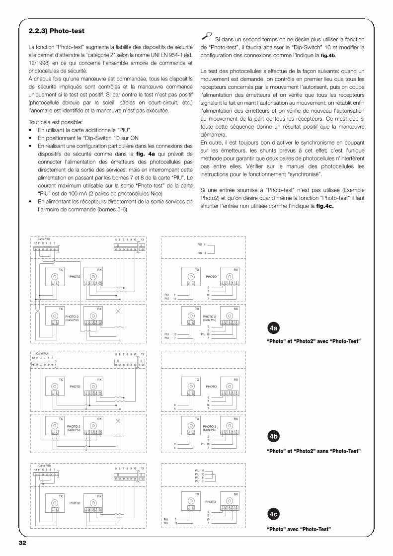
32
139 10765 8(Carte PIU)
9 8101112 7
78911 1012
(Carte PIU) 139 10765 8
1098 13765
7
10
PIU
PIU8
11
PIU
PIU
PIU 8
RX
43 51 2
6
PHOTO
5107
RX
543
PHOTO 2
21
65
(Carte PIU)
7
RX
54321
6
PHOTO
RX
107
(Carte PIU)PHOTO 2
5
10PIU6
7
531 2 4
5
RX
3 4 51 2
6
107
5
PHOTO
10PIU
PIU 11
RX
1 2
712
PIUPIU
21
3 4 51 2
RX
53 41 2
8 7
TX
1012 11 9
(Carte PIU)
1 2
TX
21
PHOTO 2
PHOTO
(Carte PIU)
7PIU
21
RX
42 3 5
65
56
21
RX
2 3 4 5
TX
PHOTO
21
TX
(Carte PIU)PHOTO 2
1 2
1
1
1 2
712
PIUPIU
RX
3 4 51 2
TX
1 2
PHOTO
12PIU
TX
TX
TX
TX
TX
“Photo” et “Photo2” avec “Photo-Test”
“Photo” et “Photo2” sans “Photo-Test”
“Photo” avec “Photo-Test”
4a
4b
4c
2.2.3) Photo-test
La fonction “Photo-test” augmente la fiabilité des dispositifs de sécuritéelle permet d’atteindre la “catégorie 2” selon la norme UNI EN 954-1 (éd.12/1998) en ce qui concerne l’ensemble armoire de commande etphotocellules de sécurité.À chaque fois qu’une manœuvre est commandée, tous les dispositifsde sécurité impliqués sont contrôlés et la manœuvre commenceuniquement si le test est positif. Si par contre le test n’est pas positif(photocellule éblouie par le soleil, câbles en court-circuit, etc.)l’anomalie est identifiée et la manœuvre n’est pas exécutée.
Tout cela est possible:• En utilisant la carte additionnelle “PIU”.• En positionnant le “Dip-Switch 10 sur ON • En réalisant une configuration particulière dans les connexions des
dispositifs de sécurité comme dans la fig. 4a qui prévoit deconnecter l’alimentation des émetteurs des photocellules pasdirectement de la sortie des services, mais en interrompant cettealimentation en passant par les bornes 7 et 8 de la carte “PIU”. Lecourant maximum utilisable sur la sortie “Photo-test” de la carte“PIU” est de 100 mA (2 paires de photocellules Nice)
• En alimentant les récepteurs directement de la sortie services del’armoire de commande (bornes 5-6).
Si dans un second temps on ne désire plus utiliser la fonctionde “Photo-test”, il faudra abaisser le “Dip-Switch” 10 et modifier laconfiguration des connexions comme l’indique la fig.4b.
Le test des photocellules s’effectue de la façon suivante: quand unmouvement est demandé, on contrôle en premier lieu que tous lesrécepteurs concernés par le mouvement l’autorisent, puis on coupel’alimentation des émetteurs et on vérifie que tous les récepteurssignalent le fait en niant l’autorisation au mouvement; on rétablit enfinl'alimentation des émetteurs et on vérifie de nouveau l’autorisationau mouvement de la part de tous les récepteurs. Ce n’est que sitoute cette séquence donne un résultat positif que la manœuvredémarrera.En outre, il est toujours bon d’activer le synchronisme en coupantsur les émetteurs, les shunts prévus à cet effet; c’est l’uniqueméthode pour garantir que deux paires de photocellules n’interfèrentpas entre elles. Vérifier sur le manuel des photocellules lesinstructions pour le fonctionnement “synchronisé”.
Si une entrée soumise à “Photo-test” n’est pas utilisée (ExemplePhoto2) et qu’on désire quand même la fonction “Photo-test” il fautshunter l’entrée non utilisée comme l’indique la fig.4c.

F
33
2.2.4) Vérification des connexions
Les prochaines opérations vous porteront à agir sur des circuits soustension, la plupart des circuits sont soumis à très basse tension desécurité et donc non dangereuse, certaines parties sont soumises à latension de secteur et donc TRÈS DANGEREUSES! Faites trèsattention à ce que vous faites et N’OPÉREZ JAMAIS SEULS!
• Alimenter l’armoire de commande et vérifier immédiatement quela tension présente entre les bornes 5-6 est d’environ 24 Vca.
• Vérifier que, après quelques instants de clignotement rapide, laLed “OK” clignote à un rythme régulier.
• Vérifier maintenant que les led relatives aux entrées aveccontacts type NC Normalement Fermé) sont allumées (toutes lessécurités actives) et que les led relatives aux entrées type NA(Normalement Ouvert) sont éteintes (aucune commandeprésente), si ce n’est pas le cas, contrôler les connexions et lebon fonctionnement des différents dispositifs. L’entrée de “Halte”intervient en éteignant aussi bien FCA que FCC.
• Vérifier la connexion exacte des microinterrupteurs de fin decourse; bouger la came du contact et vérifier que lemicrointerrupteur de fin de course intervient en éteignant la ledcorrespondante sur l’armoire de commande.
• Débloquer le battant et le porter à mi-course puis bloquer, decette manière le battant est libre de bouger aussi bien enouverture qu’en fermeture.
• Il faudra vérifier maintenant que le mouvement s’effectue dans lebon sens, c’est-à-dire contrôler la correspondance entre lemouvement prévu par la logique de commande et le mouvementeffectif des battants. Cette vérification est fondamentale, si le sensest erroné dans certains cas (par exemple en mode semi-automatique) l’automatisme pourrait fonctionner régulièrement en
apparence; en effet, le cycle “Ouvre” est semblable au cycle“Ferme” à la différence fondamentale que les dispositifs desécurité seront ignorés dans la manœuvre de fermeture, qui estgénéralement la plus dangereuse, et interviendront en ouvertureen provoquant une refermeture contre l’obstacle avec des effetsdésastreux!
• Pour vérifier si le sens de rotation est exact, il faut donner unebrève impulsion sur l’entrée “Pas-à-pas” (PP); la premièremanœuvre que l’armoire commande après avoir été alimentéeest toujours “Ouvre”, il suffit donc de vérifier si l’automatismebouge dans le sens de l’ouverture; si le mouvement s’effectuedans le mauvais sens, il faut:
� Couper alimentation� Tourner de 180° le connecteur d’alimentation du moteur et
celui des microinterrupteurs de fin de course. (Réf. “O” et Réf. “V” de la Fig.1)
� Après avoir effectué les contrôles décrits, il est préférable de vérifier de nouveau si le sens de rotation est correct en répétant le dernier point.
La led “OK” positionnée au centre de la carte, a pour fonction de signaler
l’état de la logique interne: un clignotement régulier toutes les secondes indique
que le microprocesseur interne est actif et en attente de commandes. Quand au
contraire le même microprocesseur reconnaît une variation de l’état d’une entrée
(qu’il s’agisse d’une entrée de commande ou d’un Dip-Switch des fonctions) il
génère un double clignotement rapide même si la variation ne provoque pas
d’effets immédiats. Un clignotement très rapide pendant 3 s. indique que
l’armoire de commande vient d’être alimentée et est en train d’effectuer un test
des parties internes, enfin un clignotement irrégulier indique que le test n’a pas eu
un résultat positif et qu’il y a donc une anomalie.
!
Les réglages peuvent être effectués au moyen des trimmers quiagissent en modifiant les paramètres suivants:
Temps De Travail (TL): Règle la durée maximum de la manœuvre d’ouverture ou defermeture.
Pour le réglage du Temps de Travail TL, sélectionner le mode defonctionnement “Semi-automatique” en mettant sur ON le Dip-Switch 1puis régler le trimmer TL à mi-course. Avec ces réglages effectuer uncycle d’ouverture et de fermeture, intervenir éventuellement sur leréglage du trimmer TL de manière que le temps suffise pour effectuertoute la manœuvre et qu’il reste encore une marge de 2 ou 3 s.Si même en mettant le trimmer TL au maximum le temps n’est passuffisant, couper le shunt TLM, situé sur le circuit imprimé entre lestrimmers TL et TP, de manière à obtenir un Temps de Travail plus long.
Temps De Pause (TP):Dans le fonctionnement “automatique” règle le temps entre la fin dela manœuvre d’ouverture et le commencement de la manœuvre defermeture.
Pour le réglage du Temps de Pause TP, sélectionner le mode defonctionnement “Automatique” en déplaçant sur ON le Dip-Switch 2,puis régler le trimmer TP comme on le souhaite. Pour la vérificationil faut effectuer une manœuvre d’ouverture, puis contrôler le tempsqui s’écoule avant la refermeture automatique.
Force (F): Présent sur l’armoire de commande il permet de régler la valeur dela Force maximum.
Il faut faire particulièrement attention au réglage du trimmer Force (F),ce réglage peut influencer le degré de sécurité de l’automatisme.Pour le réglage, il faut procéder par tentatives successives enmesurant la force appliquée par le battant et en la comparant à cellequi est prévue par les normes.Dans les armoires de commande RO1010 et OT21, la Force est
réglée par un sélecteur à plusieurs positions placé sur le boîtier dutransformateur d’alimentation de l’armoire.
3) Réglages:
TPTLF
TLM
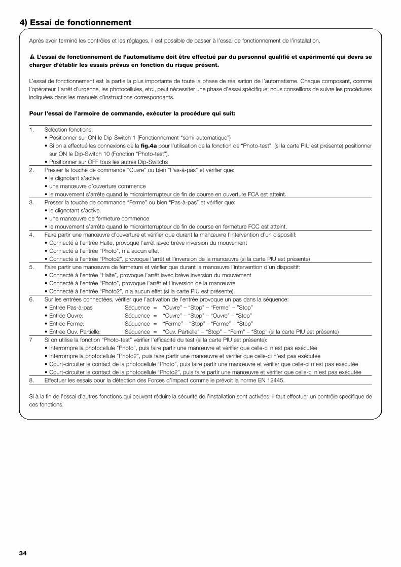
34
Après avoir terminé les contrôles et les réglages, il est possible de passer à l’essai de fonctionnement de l’installation.
L’essai de fonctionnement de l’automatisme doit être effectué par du personnel qualifié et expérimenté qui devra secharger d’établir les essais prévus en fonction du risque présent.
L’essai de fonctionnement est la partie la plus importante de toute la phase de réalisation de l’automatisme. Chaque composant, commel’opérateur, l’arrêt d’urgence, les photocellules, etc., peut nécessiter une phase d’essai spécifique; nous conseillons de suivre les procéduresindiquées dans les manuels d’instructions correspondants.
Pour l’essai de l’armoire de commande, exécuter la procédure qui suit:
1. Sélection fonctions: • Positionner sur ON le Dip-Switch 1 (Fonctionnement “semi-automatique”)• Si on a effectué les connexions de la fig.4a pour l’utilisation de la fonction de “Photo-test”, (si la carte PIU est présente) positionner
sur ON le Dip-Switch 10 (Fonction “Photo-test”).• Positionner sur OFF tous les autres Dip-Switchs
2. Presser la touche de commande “Ouvre” ou bien “Pas-à-pas” et vérifier que:• le clignotant s’active• une manœuvre d’ouverture commence• le mouvement s’arrête quand le microinterrupteur de fin de course en ouverture FCA est atteint.
3. Presser la touche de commande “Ferme” ou bien “Pas-à-pas” et vérifier que:• le clignotant s’active• une manœuvre de fermeture commence• le mouvement s’arrête quand le microinterrupteur de fin de course en fermeture FCC est atteint.
4. Faire partir une manœuvre d’ouverture et vérifier que durant la manœuvre l’intervention d’un dispositif:• Connecté à l’entrée Halte, provoque l’arrêt iavec brève inversion du mouvement• Connecté à l’entrée “Photo”, n’a aucun effet • Connecté à l’entrée “Photo2”, provoque l’arrêt et l’inversion de la manœuvre (si la carte PIU est présente)
5. Faire partir une manœuvre de fermeture et vérifier que durant la manœuvre l’intervention d’un dispositif:• Connecté à l’entrée “Halte”, provoque l’arrêt iavec brève inversion du mouvement• Connecté à l’entrée “Photo”, provoque l’arrêt et l’inversion de la manœuvre • Connecté à l’entrée “Photo2”, n’a aucun effet (si la carte PIU est présente).
6. Sur les entrées connectées, vérifier que l’activation de l’entrée provoque un pas dans la séquence:• Entrée Pas-à-pas Séquence = “Ouvre” – “Stop” – “Ferme” – ”Stop”• Entrée Ouvre: Séquence = “Ouvre” – “Stop” – “Ouvre” – “Stop”• Entrée Ferme: Séquence = “Ferme” – “Stop” - “Ferme” – “Stop”• Entrée Ouv. Partielle: Séquence = “Ouv. Partielle” – “Stop” – “Ferm” – “Stop” (si la carte PIU est présente)
7 Si on utilise la fonction “Photo-test” vérifier l’efficacité du test (si la carte PIU est présente):• Interrompre la photocellule “Photo”, puis faire partir une manœuvre et vérifier que celle-ci n’est pas exécutée • Interrompre la photocellule “Photo2”, puis faire partir une manœuvre et vérifier que celle-ci n’est pas exécutée• Court-circuiter le contact de la photocellule “Photo”, puis faire partir une manœuvre et vérifier que celle-ci n’est pas exécutée• Court-circuiter le contact de la photocellule “Photo2”, puis faire partir une manœuvre et vérifier que celle-ci n’est pas exécutée
8. Effectuer les essais pour la détection des Forces d’Impact comme le prévoit la norme EN 12445.
Si à la fin de l’essai d’autres fonctions qui peuvent réduire la sécurité de l’installation sont activées, il faut effectuer un contrôle spécifique deces fonctions.
!
4) Essai de fonctionnement
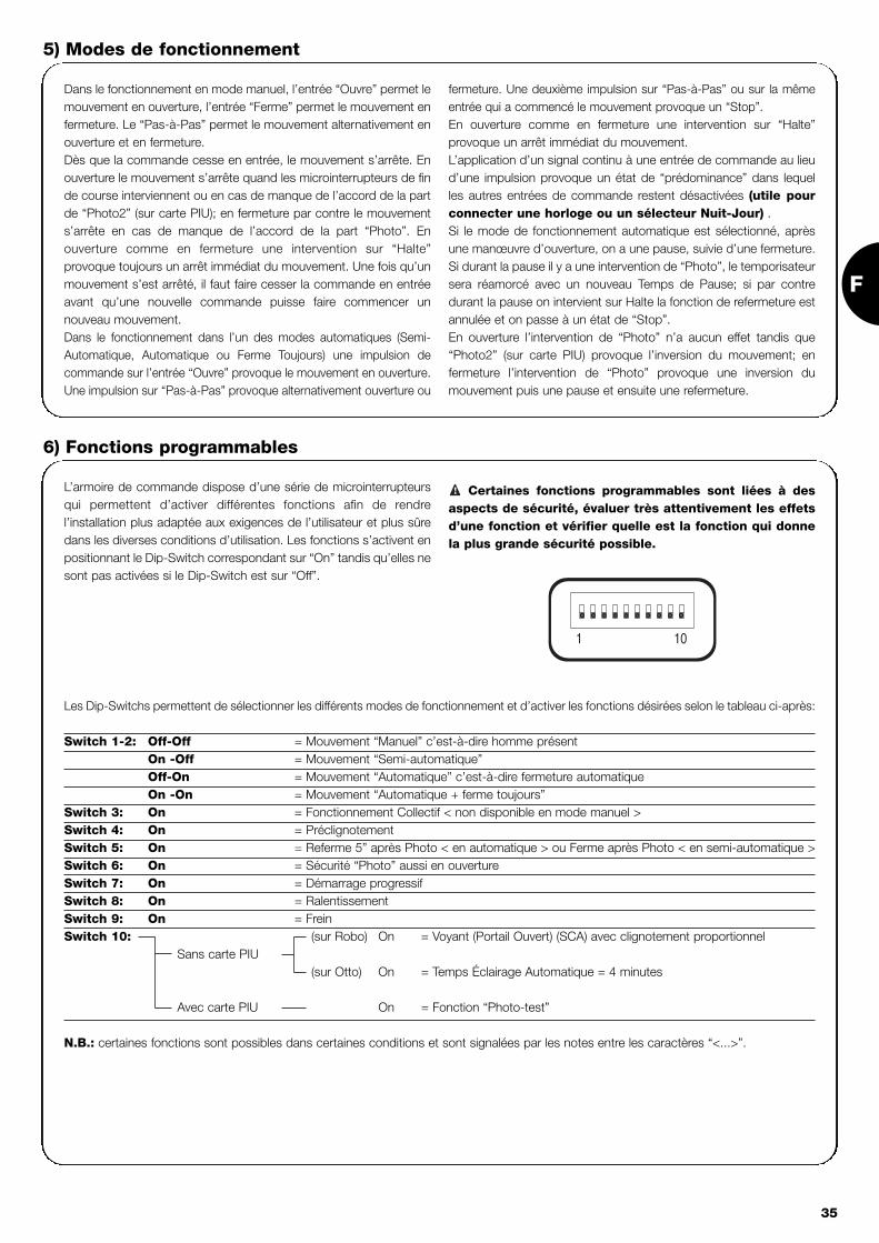
F
35
5) Modes de fonctionnement
Dans le fonctionnement en mode manuel, l’entrée “Ouvre” permet lemouvement en ouverture, l’entrée “Ferme” permet le mouvement enfermeture. Le “Pas-à-Pas” permet le mouvement alternativement enouverture et en fermeture. Dès que la commande cesse en entrée, le mouvement s’arrête. Enouverture le mouvement s’arrête quand les microinterrupteurs de finde course interviennent ou en cas de manque de l’accord de la partde “Photo2” (sur carte PIU); en fermeture par contre le mouvements’arrête en cas de manque de l’accord de la part “Photo”. Enouverture comme en fermeture une intervention sur “Halte”provoque toujours un arrêt immédiat du mouvement. Une fois qu’unmouvement s’est arrêté, il faut faire cesser la commande en entréeavant qu’une nouvelle commande puisse faire commencer unnouveau mouvement.Dans le fonctionnement dans l’un des modes automatiques (Semi-Automatique, Automatique ou Ferme Toujours) une impulsion decommande sur l’entrée “Ouvre” provoque le mouvement en ouverture.Une impulsion sur “Pas-à-Pas” provoque alternativement ouverture ou
fermeture. Une deuxième impulsion sur “Pas-à-Pas” ou sur la mêmeentrée qui a commencé le mouvement provoque un “Stop”.En ouverture comme en fermeture une intervention sur “Halte”provoque un arrêt immédiat du mouvement.L’application d’un signal continu à une entrée de commande au lieud’une impulsion provoque un état de “prédominance” dans lequelles autres entrées de commande restent désactivées (utile pourconnecter une horloge ou un sélecteur Nuit-Jour) .Si le mode de fonctionnement automatique est sélectionné, aprèsune manœuvre d’ouverture, on a une pause, suivie d’une fermeture.Si durant la pause il y a une intervention de “Photo”, le temporisateursera réamorcé avec un nouveau Temps de Pause; si par contredurant la pause on intervient sur Halte la fonction de refermeture estannulée et on passe à un état de “Stop”.En ouverture l’intervention de “Photo” n’a aucun effet tandis que“Photo2” (sur carte PIU) provoque l’inversion du mouvement; enfermeture l’intervention de “Photo” provoque une inversion dumouvement puis une pause et ensuite une refermeture.
L’armoire de commande dispose d’une série de microinterrupteursqui permettent d’activer différentes fonctions afin de rendrel’installation plus adaptée aux exigences de l’utilisateur et plus sûredans les diverses conditions d’utilisation. Les fonctions s’activent enpositionnant le Dip-Switch correspondant sur “On” tandis qu’elles nesont pas activées si le Dip-Switch est sur “Off”.
Certaines fonctions programmables sont liées à desaspects de sécurité, évaluer très attentivement les effetsd’une fonction et vérifier quelle est la fonction qui donnela plus grande sécurité possible.
!
Les Dip-Switchs permettent de sélectionner les différents modes de fonctionnement et d’activer les fonctions désirées selon le tableau ci-après:
Switch 1-2: Off-Off = Mouvement “Manuel” c’est-à-dire homme présentOn -Off = Mouvement “Semi-automatique”Off-On = Mouvement “Automatique” c’est-à-dire fermeture automatiqueOn -On = Mouvement “Automatique + ferme toujours”
Switch 3: On = Fonctionnement Collectif < non disponible en mode manuel >Switch 4: On = PréclignotementSwitch 5: On = Referme 5” après Photo < en automatique > ou Ferme après Photo < en semi-automatique >Switch 6: On = Sécurité “Photo” aussi en ouvertureSwitch 7: On = Démarrage progressifSwitch 8: On = RalentissementSwitch 9: On = FreinSwitch 10: (sur Robo) On = Voyant (Portail Ouvert) (SCA) avec clignotement proportionnel
Sans carte PIU (sur Otto) On = Temps Éclairage Automatique = 4 minutes
Avec carte PIU On = Fonction “Photo-test”
N.B.: certaines fonctions sont possibles dans certaines conditions et sont signalées par les notes entre les caractères “<...>”.
6) Fonctions programmables
101

36
6.1) Description des fonctionsNous reportons maintenant une brève description des fonctions qui peuvent s’activer en portant sur “On” le Dip-Switch correspondant
Switch 1-2: Off-Off = Mouvement “Manuel” (homme présent)On-Off = Mouvement “Semi-automatique”Off-On = Mouvement “Automatique” (fermeture automatique)On-On = Mouvement “Automatique + Ferme Toujours”
Dans le fonctionnement “Manuel” le mouvement est exécuté seulement jusqu’à la présence de la commande (touche pressée).En “Semi-automatique” il suffit d’une impulsion de commande et tout le mouvement est exécuté jusqu’à l’expiration du Temps de Travail ouquand le microinterrupteur de fin de course est atteint. Dans le fonctionnement en mode “Automatique” après une ouverture, il y a une pauseet donc la fermeture a lieu automatiquement.La fonction “Ferme Toujours” intervient après un manque d’alimentation; si la logique de commande détecte le portail ouvert, une manœuvrede fermeture démarre automatiquement, précédée de 5 s. de préclignotement.
Switch 3: On = Fonctionnement Collectif (non disponible en mode manuel)Dans le fonctionnement collectif, une fois qu’un mouvement en ouverture a démarré, la manœuvre ne peut pas être interrompue par d’autresimpulsions de commande sur Pas-à-Pas ou “Ouvre” jusqu’à la fin du mouvement en ouverture.Dans le mouvement en fermeture une nouvelle impulsion de commande provoque l’arrêt et l’inversion du mouvement en ouverture.
Switch 4: On = PréclignotementÀ l’impulsion de commande on a d’abord l’activation du clignotant puis, au bout de 5 s. (2 en manuel), le mouvement commence.
Switch 5: On = Referme 5 s. après “Photo” < en “automatique” > ou “Ferme” après “Photo” < en “Semi-automatique” >Cette fonction, si on est en mode Automatique, permet de maintenir le portail ouvert seulement le temps nécessaire au transit, en effet, à lafin de l’intervention de “Photo” la manœuvre s’arrête. Au bout de 5 s. une manœuvre de fermeture commencera automatiquement. Si onest en mode Semi-automatique, une intervention de “Photo” dans la manœuvre de fermeture active la fermeture automatique avec le Tempsde Pause réglé.
Switch 6: On = Sécurité “Photo” également en ouvertureNormalement la sécurité “Photo” est active seulement dans la manœuvre de fermeture, si le Dip-Switch 6 est positionné sur “ON”l'intervention du dispositif de sécurité provoque une interruption du mouvement également en ouverture.Si on est en mode Semi-automatique ou Automatique on aura la reprise du mouvement en ouverture jusque après la libération de la photocellule.
Switch 7: On = Démarrage progressifExécute le début du mouvement de manière progressive en évitant les secousses de l’automatisme.
Switch 8: On = Ralentissement Le ralentissement consiste en une réduction de la vitesse à 30% de la vitesse nominale de manière à éviter des secousses inutiles à la finde la manœuvre.
La fonction de ralentissement en plus de diminuer la vitesse de l’automatisme réduit de 70% le couple du moteur. Dans les automatismes nécessitant
un couple élevé, cette réduction pourrait provoquer l’arrêt immédiat du moteur.
Version ROBO - THOR:A la fin de la manœuvre d’ouverture ou de fermeture due àl’expiration du Temps de Travail, une phase de ralentissement estexécutée, de la même durée que le Temps de Travail.Si la manœuvre se termine par l’intervention des microinterrupteursde fin de course, la phase de ralentissement n’est pas exécutée, ilfaut donc régler le Temps de Travail pour que le ralentissementcommence 30-50 cm avant l’intervention des microinterrupteurs defin de course.
Version OTTO:A la fin de la manœuvre de fermeture, la phase de ralentissementdure 3 s. si el le est déclenchée par l ’ interruption desmicrointerrupteurs, de même si elle est déclenchée par le Temps deTravail celle ci durera le Temps de Travail programmé (pour un bonfonctionnement du ralentissement, il est conseillé d’utiliser desmicrointerrupteurs de fin de course). Dans la manœuvre d’ouverture, le ralentissement n’est pas effectuémais il est remplacé par un arrêt progressif.
Si on utilise la fonction de ralentissement sur desinstallations sensibles et si elle dure plus de 3 s., il fautinsérer sur les bornes d’alimentation de secteur àproximité de l’armoire de commande un filtre de secteur
! d’au moins 6A avec atténuation de 30 dB pour ne pasdépasser les limites d’émission électromagnétiqueprescrites par la norme EN 50081-1.

F
37
Switch 9: On = FreinÀ la fin du mouvement, l’automatisme prévoit dans ce cas une procédure de freinage du moteur, d’abord légère puis plus forte de manièreà arrêter le portail rapidement mais sans secousses.
Cette fonction permet d’effectuer à chaque début de manœuvre un contrôle du bon fonctionnement des photocellules. Voir chapitre “Photo-test”.
Pour réaliser un automatisme avec 2 battants qui travaillent enantagonisme, il faut:• Utiliser deux moteurs avec les armoires connectées comme
l’indique la fig. 5.• Connecter le clignotant et le voyant Portail Ouvert indifféremment
à l’une des deux armoires de commande. • Les entrées doivent être connectées en parallèle.
• Le “Commun” des entrées peut être connecté à l’une des 2armoires de commande.
• Connecter ensemble les 0Volt (Borne 5) des deux armoires decommande.
• La fonction “Photo-test” ne doit pas être utilisée.• Il est bon d’activer la fonction “Collectif” (Dip-Switch 3) qui
permet de resynchroniser les battants si les 2 armoires decommande perdent le synchronisme.
7) Utilisation de deux armoires de commandes sur battants antagoniques
Switch 10: On
ROBO - THOR
Sans carte PIU branchée:• Voyant Portail Ouvert avec clignotement proportionnel
Avec carte PIU branchée:• “Photo-test”
OTTO
Sans carte PIU branchée:• Temps Éclairage Automatique = 4 minutes
Avec carte PIU branchée:• “Photo-test”
5

38
Carte PIUL’armoire de commande contient déjà toutes les fonctions qui sont utilisées dans une installation normale, pour satisfaire les demandes d’u-tilisation dans des installations particulières, il est possible d’utiliser une carte en option “Carte PIU” qui permet d’ajouter de nouvelles fonc-tions telles que: Feux de signalisation, Éclairage Automatique, Serrure électrique, “Photo2”, ouverture partielle et “Photo-test”.
Rouge = Feu rougeIl est normalement toujours éteint et s’allumedurant le mouvement du portail
Vert = Feu vertIl reste normalement allumé et s’éteint durant lemouvement du portail
Serrure électr. = Sortie pour commande serrure électriqueLa serrure électrique est activée pendant 1,5 s.au début du mouvement en ouverture.
Écl. automatique/ Photo-test = Sortie qui si elle est utilisée pour la commande
Éclairage Automatique, permet d’allumer audébut “Photo-test” de chaque mouvement unÉclairage Automatique qui reste allumé jusqu’à lafin du mouvement et pendant un tempssupplémentaire programmé avec le trimmerT.Cor. présent sur la carte “PIU”.Si la fonction “Photo-test” est activée (Dip-Switch10 = ON) cette sortie permet d’effectuer un testdes photocellules au début de la manœuvre.
Ouv. partielle = Entrée pour ouverture partielle (Ouv. Part.,Stop, Ferme, Stop). Effectue la même fonctionque Pas-à-Pas sur la carte principale, avec lamanœuvre d’ouverture dure le temps fixé sur letrimmer T.AP.P. présent sur la carte “PIU”.
Photo 2 = Entrée 2e dispositif de sécurité. Ce dispositif desécurité intervient uniquement dans lamanœuvre d’ouverture en provoquant un arrêtdu mouvement, avec éventuelle refermeture sil’armoire de commande est programmée avecun mode de fonctionnement “Semi-automatique” ou “Automatique”.
24 V = Sortie 24V utilisable pour l’alimentation deservices comme les photocellules ou autre. Laborne 11 est aussi la borne en commun pour lesentrées.
Carte “RADIO”L’armoire comprend un connecteur pour brancher une carte radio, produite par Nice, qui permet d’agir sur l’entrée de “Pas-à-Pas” et com-mander de cette manière l’armoire à distance avec un émetteur.
8) Accessoires en option
L’armoire de commande, en tant que partie électronique, n’a besoind’aucune maintenance particulière. Vérifier dans tous les caspériodiquement (au moins tous les 6 mois), le bon fonctionnement etle réglage du dispositif de réglage de la Force du moteur, agiréventuellement sur le trimmer de réglage.
Refaire en entier la phase d’essai de fonctionnement pour contrôlerle bon fonctionnement des microinterrupteurs de fin de course, desdispositifs de sécurité (photocellules, barres palpeuses, etc.) et lefonctionnement correct du clignotant.
9) Maintenance
Ce produit est constitué de différents types de matériaux dontcertains peuvent être recyclés.Informez-vous sur les méthodes de recyclage ou de mise au rebuten suivant les normes en vigueur sur le plan local.
Certains composants électriques peuvent contenir dessubstances polluantes, ne les abandonnez pas dans lanature.
!
10) Mise au rebut

F
39
Ce chapitre est un guide visant à aider l’installateur à résoudrequelques uns des problèmes les plus courants qui peuvent seprésenter durant l’installation.
Aucune led n’est allumée:• Vérifier si l’armoire de commande est alimentée (vérifier que la
tension de secteur arrive aux bornes 1-2 et qu’il y a une tensiond’environ 24Vca aux bornes 5-6)
• Vérifier si les 2 fusibles d’alimentation sont intacts et si aucune Ledn’est allumée même dans ce cas, on est probablement en présenced’une panne grave et l’armoire de commande devra être remplacée.
La led OK clignote régulièrement mais les LED ENTRÉESne reflètent pas l’état des entrées respectives• Vérifier attentivement les connexions sur les bornes des entrées
7÷13.
La manœuvre ne démarre pas• Vérifier que les Led des sécurités “Halte” (FCA + FCC), “Photo”,
et éventuellement “Photo2” sont allumées et que la Led de lacommande qui est activée (“Pas-à-Pas”, “Ouvre” o “Ferme”s’allume pendant la durée de la commande.
Durant le mouvement le portail effectue une inversionLes causes qui provoquent une inversion sont: • Une intervention des photocellules (“Photo2” en ouverture, ou
“Photo” durant la fermeture); dans ce cas contrôler lesconnexions des photocellules et vérifier éventuellement les Ledde signalisation des entrées.
11) Que faire si ….
Alimentation de secteur : 230 Vca 50/60 Hz
Versions/V1 : 120 Vca 50/60 HzCourant Max. services 24 V : 200 mASortie clignotant : Pour clignotants à la tension de secteur, puissance maximum 40 WSortie voyant Portail Ouvert “SCA” : Pour voyants 24Vac, puissance maximum 2 W Température de fonctionnement : -20 ÷ 70 °CTemps de Travail sur ROBO/THOR : Réglable de 2.5 à >60 s. ou de <50 à >120 s avec TLMTemps de Travail sur OTTO : Réglable de 2.5 à >20 s. ou de <20 à >40 s avec TLMTemps de Pause : Réglable de 5 à >160 s.
sur Carte PIUTemps Ouv. Partielle ROBO/THOR : Réglable de 1 à > 30 s.Temps Ouv. Partielle OTTO : Réglable de 1 à > 14 s.Temps éclairage automatique : Réglable de 1 à > 180 s.
12) Caractéristiques techniques

40
Steuerung toröffnerrobo, thor, otto
Hinweise:
Die vorliegende Anleitung ist nur für technisches Personalbestimmt, das für die Installation qualifiziert ist. Keine imvorliegenden Heft enthaltene Information kann alsinteressant für den Endbenutzer betrachtet werden! Die vorliegende Anleitung bezieht sich nur auf dieseSteuerung und darf nicht für andere Produkte verwendetwerden.Es wird empfohlen, alle Anweisungen mindestens einmal vor derInstallation genau zu lesen.
!
Inhalt: S.
1 Beschreibung des Produktes 41
2 Installation 422.1 Typische Anlage 422.2 Elektrische Anschlüsse 422.2.1 Schaltplan 432.2.2 Beschreibung der Anschlüsse 432.2.3 Photozellentest 442.2.4 Überprüfung der Anschlüsse 45
3 Einstellungen 45
4 Prüfung 46
5 Betriebsarten 47
S.
6 Programmierbare Funktionen 476.1 Beschreibung der Funktionen 48
7 Verwendung von 2 Steuerungen an entgegengesetzten Torflügeln 49
8 Sonderzubehör 50
9 Wartung 50
10 Entsorgung 50
11 Was tun, wenn... 51
12 Technische Merkmale 51

D
41
1) Beschreibung des Produktes:Mit dieser Steuerung für die Automatisierung von Toren und Türenkönnen die Toröffner ROBO, OTTO, THOR in einphasigemWechselstrom betrieben werden.Je nach zu steuerndem Toröffner weist die Steuerung Varianten auf,zum Beispiel: “Krafteinstellung”, “Kontrolllampe Tor Geöffnet” und“Zusätzliche Beleuchtung”.Weiterhin sind verschiedene Funktionen vorhanden, die über “Dip-Switch” (Mini-Wählschalter) auswählbar sind, und Einstellungen, diedurch Trimmer erfolgen.
An der Steuerung, neben den Eingängen, befinden sich Leds, dieihren Zustand anzeigen; eine zuzügliche Led in der Nähe desMikroprozessors meldet den korrekten Betrieb der internen Logik.
Damit die Teile leichter erkennbar sind, werden in Abb.1 diewichtigsten Komponenten gezeigt .
LMNOP
J
QRST
V U
I
X
W
YHG
FZ
EDCBA
CH
P.P.
AP
FOTO
FCA
FCCOK
Dip-Switch für die Auswahl der FunktionenTrimmer für KrafteinstellungTrimmer (TL) für Einstellung der ArbeitszeitTrimmer (TP) für Einstellung der PausenzeitKlemmenbrett für Antenne und 2. KanalSteckanschluss für RADIO-KarteLed für die Anzeige des Zustandes der EingängeKlemmenbrett Steuereingänge / - ausgänge“Gemeines” RelaisKlemmenbrett Stromversorgung / BlinkleuchteVerbinder für PrimärtransformatorLiniensicherung (5A)“Verbinder” für Ausgang Zusätzliche Beleuchtung (nur für OTTO)Ausgang MotorversorgungSteckanschluss KondensatorSpitzenstromrelaisTriac Zusätzliche Beleuchtung (nur für OTTO)Triac “Schließt”Triac “Öffnet”Verbinder für SekundärtransformatorEingang Endschalter FCA / FCCNiederspannungssicherung (500mA)Steckanschluss PIU-KarteOK-LedMikroprozessor
ABCDEFGHIJLMNOPQRSTUVWXYZ
1
Produkt-Code* Code der Steuerung* Zusatzfunktion
ROBORO1000RO1020
ROA3 Trimmer Krafteinstellung
RO1010 ROA4 Spitzenstromrelais
THOR TH1551 THA5 Trimmer KrafteinstellungTH2251 THA6 Spitzenstromrelais
OTTO OT21 OTA1 Ausgang Zusätzliche Beleuchtung
* = für die 120 V 50/60 Hz Version dem Code V hinzufügen.

42
2.1) Typische Anlage
Wir geben hier ein typisches Beispiel, mit dem wir einige Ausdrücke und Aspekte klären wollen.
ROBO / THOR OTTO
1) Photozellenpaar “Photo”2) Blinkleuchte3) Schlüsseltaster4) Sicherheitsleiste5) Photozellenpaar “Photo 2”
Insbesondere erinnern wir daran, dass:• alle von NICE hergestellten Photozellen über das Synchro-System verfügen, mit dem Probleme wie Interferenzen zwischen zwei
Photozellenpaaren beseitigt werden (für weitere Details siehe Anweisungen der Photozellen) • das Photozellenpaar “Photo” in Öffnung keine Wirkung hat, wogegen es in Schließung eine Umkehrung verursacht.• das Photozellenpaar “Photo2” in Schließung keine Wirkung hat, wogegen es in Öffnung eine Umkehrung verursacht.
Wir erinnern daran, dass automatische Tür- undToranlagen nur von technisch qualifiziertem Personalunter voller Einhaltung der gesetzlichen Vorschriften
installiert werden dürfen. Die Anweisungen im Heft“Hinweise für den Installateur” genau befolgen.
!
2) Installation:
2a 2b
PHOTO
PHOTO
PHOTO 2
5
3
2
1
3
4
PHOTO
21
2.2) Elektrische Anschlüsse
Damit die Sicherheit des Bedieners gewährleistet wirdund Schäden an den Komponenten vermieden werden,darf die Steuerung nicht gespeist sein, wenn dieAnschlüsse durchgeführt oder die verschiedenen Karteneingeschaltet werden.
• Die Steuerung über ein Kabel mit Querschnitt 3 x 1,5mm2
versorgen; ist der Abstand zwischen Steuerung und Erdschlusslänger als 30m, muss ein Erdleiter in der Nähe der Steuerungvorgesehen werden.
• Für die Anschlüsse des Teils in Niedrigstspannung, Leiter miteinem Mindestquerschnitt von 0,25mm2 verwenden.
• Im Falle einer Länge über 30m abgeschirmte Kabel verwendenund das Geflecht nur auf der Seite der Steuerung erden.
• Anschlüsse an Kabeln, die sich in unterirdischen Gehäusenbefinden, sind zu vermeiden, auch wenn das Gehäusevollkommen dicht ist.
• NC-Eingänge (gewöhnlich geschlossene Eingänge), falls nichtbenützt, sind mit dem “Gemeinen 24 V” zu überbrücken (außerdie Eingänge der Photozellen, falls die Funktion Photozellentesteingeschaltet ist – für weitere Erläuterungen siehe AbschnittPhotozellentest).
• Falls mehrere NC-Kontakte für den gleichen Eingang vorhandensind, müssen sie untereinander Seriengeschaltet werden.
• NA-Eingänge (gewöhnlich geöffnete Eingänge), falls nichtbenützt, sind frei zu lassen.
• Falls für den gleichen Eingang mehrere NA-Kontakte vorhandensind, müssen sie untereinander Parallelgeschaltet werden.
• Die Kontakte müssen unbedingt mechanische Kontakte und freivon jedem Potential sein; stufenweise Anschlüsse wie “PNP","NPN" , "Open Collector" usw. sind unzulässig.
!

D
43
2.2.1) Schaltplan
2.2.2) Beschreibung der Anschlüsse
Es folgt eine kurze Beschreibung der möglichen Anschlüsse der Steuerung nach außen.
Klemmen Funktionen Beschreibung
1-2 : Speisung = Netzspannungsversorgung
3-4 : Blinkleuchte = Ausgang für Anschluss der Blinkleuchte mit Netzspannung ( max. 40W)
5-6 : 24 Vac = Spannungsversorgung Nebeneinrichtungen 24 Vac (Photo, Radio, usw.) max 200mA
7 : Gemein = Gemeiner Leiter für alle Eingänge
8 : SCA = Kontrolllampe Tor geöffnet 24 Vac max. 2W ( Nicht vorhanden in der Version OTTO)
9 : Halte = Eingang mit Stoppfunktion des Vorgangs, mit kurzer Umkehrung der Bewegung
10 : Photo = Eingang für Sicherheitsvorrichtungen (Photozellen, Sicherheitsleisten)
11 : Schrittzyklus = Eingang für zyklische Bewegung (AUF - STOP - ZU - STOP)
12 : Öffnet = Eingang für Bewegung in Öffnung
13 : Schließt = Eingang für Bewegung in Schließung
41-42 : 2. Funkkanal = Ausgang eventueller zweiter Funkempfängerkanal
43-44 : Antenne = Eingang Funkempfängerantenne
3

44
2.2.3) Photozellentest
“Photozellentest” ist eine sehr gute Lösung, was die Zuverlässigkeitder Sicherheitsvorrichtungen betrifft, dank der die Einheit Steuerungmit Sicherheitsphotozellen in “Kategorie 2” gemäß der Norm UNI EN954-1 (Ausgabe 12/1998) eingestuft wird.Jedes Mal, wenn eine Bewegung erfolgt, werden die betreffendenSicherheitsvorrichtungen kontrolliert, und erst wenn alles in Ordnungist, wird die Bewegung beginnen. Ist der Test dagegen erfolglos (vonder Sonne geblendete Photozelle, kurzgeschlossene Kabel, usw.), wirdder Defekt festgestellt und die Bewegung findet nicht statt
• Wenn die Zusatzkarte PIU verwendet wird.• Wenn Dip-Switch 10 auf ON gestellt ist.• Wenn die Anschlüsse der Sicherheitsvorrichtungen wie in Abb. 4a
gestaltet werden, wobei die Versorgung der Photozellensender nichtdirekt am Ausgang der Nebeneinrichtungen abgeht, sondern durchdie Klemmen 7 und 8 der Karte PIU geht, wodurch dieseVersorgung unterbrochen wird. Der verwendbare Höchststrom amAusgang “Photozellentest” der Karte PIU ist 100mA (2 NicePhotozellenpaare).
• Wenn die Empfänger direkt vom Ausgang Nebeneinrichtungender Steuerung (Klemmen 5-6) versorgt werden.
Falls man die Funktion Photozellentest später nicht mehr verwenden
will, so muss der Dip-Switch 10 nach unten gestellt werden und die
Anschlüsse sind wie in Abb. 4b gezeigt zu ändern .
Beschreibung des Vorgangs Photozellentest: wenn eine Bewegungverlangt ist, wird als erstes kontrolliert, ob alle betreffenden Empfängerihre Zustimmung geben, dann wird die Versorgung zu den Sendernabgeschaltet und geprüft, ob alle Empfänger diese Tatsache melden,indem ihre Zustimmung weggenommen wird; am Ende werden dieSender wieder mit Spannung versorgt und es wird erneut geprüft, obdie Zustimmung aller Empfänger vorhanden ist. Nur wenn dieseSequenz erfolgreich ausgeführt wird, wird eine Bewegung stattfinden. Weiterhin sollte der Synchronismus über Durchschneiden derjeweiligen Überbrückungen an den Sendern aktiviert werden; dies istdie einzige Art, um zu gewährleisten, dass sich zwei Photozellenpaarenicht überschneiden. In der Anleitung der Photozellen dieAnweisungen für den synchronisierten Betrieb nachlesen.
Sollte ein “Photozellentesteingang” nicht benützt werden (z.B. Photo2)und man trotzdem aber die Funktion “Photozellentest” will, muss dernicht benützte Eingang wie in Abb.4c gezeigt überbrückt werden.
139 10765 8(Karte PIU)
9 8101112 7
78911 1012
(Karte PIU) 139 10765 8
1098 13765
7
10
PIU
PIU8
11
PIU
PIU
PIU 8
RX
43 51 2
6
PHOTO
5107
RX
543
PHOTO 2
21
65
(Karte PIU)
7
RX
54321
6
PHOTO
RX
107
(Karte PIU)PHOTO 2
5
10PIU6
7
531 2 4
5
RX
3 4 51 2
6
107
5
PHOTO
10PIU
PIU 11
RX
1 2
712
PIUPIU
21
3 4 51 2
RX
53 41 2
8 7
TX
1012 11 9
(Karte PIU)
1 2
TX
21
PHOTO 2
PHOTO
(Karte PIU)
7PIU
21
RX
42 3 5
65
56
21
RX
2 3 4 5
TX
PHOTO
21
TX
(Karte PIU)PHOTO 2
1 2
1
1
1 2
712
PIUPIU
RX
3 4 51 2
TX
1 2
PHOTO
12PIU
TX
TX
TX
TX
TX
“Photo” und “Photo2” mit “Photozellentest”
“Photo” und “Photo2” ohne “Photozellentest”
“Photo” mit “Photozellentest”
4a
4b
4c

D
45
2.2.4) Überprüfung der Anschlüsse
Bei Durchführung der nachfolgenden Arbeiten werden Sie anKreisläufen arbeiten, die unter Spannung stehen; die meisten Teile derKreisläufe stehen unter Niedrigstspannung und sind daher ungefährlich;einige Teile stehen unter Netzspannung, sie sind daher SEHRGEFÄHRLICH! Gehen Sie daher sehr vorsichtig vor und NIE ALLEIN!
• Die Steuerung mit Spannung versorgen und sofort prüfen, obzwischen den Klemmen 5-6 ca. 24 Vac vorhanden ist.
• Prüfen, ob die OK-Led nach kurzfristigem Schnellblinken auf einregelmäßiges Blinken übergeht.
• Nun prüfen, ob die Leds der Eingänge mit NC-Kontakteneingeschaltet sind (alle Sicherheitsvorrichtungen aktiviert) und ob dieLeds der NA-Eingänge abgeschaltet sind (kein Befehl vorhanden);im gegenteiligen Fall die Anschlüsse und Betriebstüchtigkeit derverschiedenen Vorrichtungen kontrollieren. Der Eingang von “Stop”spricht an, wenn sowohl FCA als auch FCC abgeschaltet sind.
• Überprüfen, ob die Endschalter richtig angeschlossen sind; denEndschalterhebel bewegen und prüfen, ob der jeweiligeEndschalter anspricht, wobei sich die entsprechende Led an derSteuerung ausschalten muss.
• Den Torflügel entriegeln und auf Hälfte Lauf bringen, dannverriegeln, so dass sich der Torflügel sowohl in Öffnung als auchin Schließung frei bewegen kann.
• Nun muss geprüft werden, ob die Bewegung in die korrekteRichtung erfolgt, d.h. ob die von der Steuerung vorgeseheneBewegung mit der tatsächlichen Bewegung der Torflügelübereinstimmt. Diese Überprüfung ist sehr wichtig; wenn dieRichtung verkehrt ist, könnte der Automatismus in einigen Fällen(zum Beispiel im “Halbautomatischen” Betrieb) anscheinendordnungsgemäß funktionieren, da in der Tat der Zyklus “AUF”
dem Zyklus “ZU” ähnlich ist, jedoch mit dem grundlegendenUnterschied, dass die Sicherheitsvorrichtungen beimSchließvorgang, der gewöhnlich der gefährlichste ist, ignoriertwerden und bei der Öffnung ansprechen und ein erneutesSchließen verursachen werden, wobei das Hindernis mitverheerenden Wirkungen getroffen wird!;
• Um zu prüfen, ob der Drehsinn korrekt ist, genügt ein kurzer Impulsauf den Eingang Schrittbetrieb; die erste, von der Steuerungausgeführte Bewegung nach ihrer Spannungsversorgung ist immerAUF, es genügt daher, zu prüfen, ob sich der Automatismus in dieÖffnungsrichtung bewegt; falls die Bewegung dagegen in diefalsche Richtung erfolgt, muss:
� die Spannungsversorgung abgeschaltet werden� der Stromverbinder des Motors um 180° gedreht und jenerder Endschalter (siehe “O” und “V” in Abb.1) umgekehrt werden.� Nachdem das Beschriebene ausgeführt worden ist, erneutprüfen, ob der Drehsinn korrekt ist und gegebenenfalls denletzten Punkt wiederholen.
Die “OK”-Led in der Mitte der Karte hat die Aufgabe, den Zustand der
internen Logik zu melden: ein regelmäßiges Blinken einmal pro Sekunde
bedeutet, dass der interne Mikroprozessor aktiv ist und auf Befehle wartet.
Wenn der Mikroprozessor dagegen eine Änderung des Zustandes eines
Eingangs wahrnimmt (sowohl Steuereingang als auch Dip-Switch der
Funktionen), wird ein schnelles Doppelblinken verursacht, auch wenn diese
Änderung keine sofortigen Wirkungen hat. Ein sehr schnelles, 3 S. langes
Blinken bedeutet, dass die Steuerung soeben mit Spannung versorgt worden
ist und einen Test der Innenteile ausführt; ein konstantes Blinken bedeutet,
dass der Test nicht erfolgreich war und dass daher ein Defekt vorliegt.
!
Die Einstellungen werden über Trimmer ausgeführt, die folgendeParameter verändern:
Arbeitszeit (TL): Die Arbeitszeit regelt die Höchstdauer der Bewegung in Öffnungoder Schließung.
Für die Einstellung der Arbeitszeit TL, die Betriebsart“Halbautomatisch” wählen und den Dip-Switch 1 auf On stellen, dannden Trimmer TL auf etwa halben Weg regeln. Mit diesen Einstellungeneinen Zyklus in Öffnung und in Schließung ausführen undgegebenenfalls den Trimmer TL so regulieren, dass während dieserZeit die ganze Bewegung ausgeführt werden kann und noch eineZeitspanne von 2 oder 3 Sekunden bleibt. Falls keine ausreichendeZeit erzielt wird, auch wenn der Trimmer auf das Maximum gestelltwird, kann die Überbrückung TLM auf der gedruckten Schaltplattezwischen den Trimmern TL und TP durchgeschnitten und dadurcheine Arbeitsmehrzeit erhalten werden.
Pausezeit (TP):Zur Einstellung im “automatischen” Betrieb der Zeit zwischen demEnde der Öffnungsbewegung und dem Anfang der Schließbewegung.
Für die Einstellung der Pausezeit TP, die Betriebsart “Automatisch”wählen und den Dip-Switch 2 auf On stellen, dann den Trimmer TPbeliebig regeln. Für die Überprüfung muss eine Öffnungsbewegungausgeführt werden, dann die Zeit kontrollieren, die vor demautomatischen Wiederschließen vergeht.
Kraft (F): An der Steuerung vorhanden, dient diese Einstellung zur Regulierungder Höchstkraft.
Besonders aufmerksam muss man bei der Einstellung des Trimmerskraf (F) sein, da diese Einstellung den Sicherheitsgrad derAutomatisierung beeinflussen kann. Zur Einstellung mehrmaligeVersuche machen, dabei die vom Torflügel angewendete Kraftmessen und mit dem laut Vorschriften vorgesehenen Wertvergleichen.An den Steuerungen RO1010 und OT21 wird die Kraft über einenmehrstelligen Wählschalter am Gehäuse desVersorgungstransformators der Steuerung reguliert.
3) Einstellungen:
TPTLF
TLM

46
Nachdem die Überprüfungen und Einstellungen beendet sind, kann man auf die Prüfung der Anlage übergehen.
Die Automatisierung muss von erfahrenem Fachpersonal geprüft werden, das die vorzusehenden Tests je nachvorhandenem Risiko festzulegen hat.
Die Prüfung ist das Wichtigste bei der Durchführung der ganzen Automatisierung. Jedes einzelne Teil wie Motor, Notstop, Photozellen usw.kann eine spezielle Prüfung erfordern, daher wird empfohlen, sich an die Verfahren in den jeweiligen Anleitungen zu halten.
Für die Prüfung der Steuerung sind der Reihe nach folgende Schritte auszuführen:
1. Auswahl der Funktionen:• Den Dip-Switch 1 auf ON stellen (halbautomatischer Betrieb)• Sind die Anschlüsse in Abb.4 für die Verwendung von Photozellentest ausgeführt worden (falls die Karte PIU vorhanden ist), den
Dip-Switch 10 (Funktion Photozellentest) auf ON stellen.• Alle anderen Dip-Switch auf OFF stellen.
2. Auf die Steuertaste “Öffnet” oder “Schrittbetrieb” drücken und prüfen, ob:• sich die Blinkleuchte aktiviert• eine Öffnungsbewegung beginnt• die Bewegung anhält, wenn der Endschalter FCA in Öffnung erreicht wird.
3. Auf die Steuertaste “Schließt” oder “Schrittbetrieb” drücken und prüfen, ob:• sich die Blinkleuchte aktiviert• eine Schließbewegung beginnt• die Bewegung anhält, wenn der Endschalter FCC in Schließung erreicht wird.
4. Eine Bewegung in Öffnung beginnen und prüfen, ob das Ansprechen einer Vorrichtung während der Bewegung:• die am Eingang Stop angeschlossen, verursacht er das Anhalten mit kurzer Umkehrung der Bewegung • die am Eingang Photo angeschlossen ist, keine Wirkung hat• die am Eingang Photo2 angeschlossen ist, das Anhalten und die Umkehrung der Bewegung verursacht (falls die Karte PIU vorhanden ist).
5. Eine Bewegung in Schließung beginnen und prüfen, ob das Ansprechen einer Vorrichtung während der Bewegung:• die am Eingang Stop angeschlossen, verursacht er das Anhalten mit kurzer Umkehrung der Bewegung• die am Eingang Photo angeschlossen ist, das Anhalten und die Umkehrung der Bewegung verursacht• die am Eingang Photo2 angeschlossen ist, keine Wirkung hat (falls die Karte PIU vorhanden ist).
6. An den angeschlossenen Eingängen prüfen, ob die Aktivierung des Eingangs einen Schritt in der folgenden Sequenz verursacht:• Eingang Schrittbetrieb: Sequenz = “Auf” – “Stop” – “Zu” – ”Stop”• Eingang Öffnet: Sequenz = “Auf” – “Stop” – “Auf” – “Stop”• Eingang Schließt: Sequenz = “Zu” – “Stop” - “Zu” – “Stop”• Eingang Teil-Öffnung: Sequenz = “Teilweise Auf” – “Stop” – ”Zu” – “Stop” (falls die Karte PIU vorhanden ist).
7 Falls die Funktion Photozellentest benützt wird, die Effizienz des Test überprüfen (falls die Karte PIU vorhanden ist):• Die Photozelle “Photo” abblenden, dann eine Bewegung beginnen und prüfen, dass diese nicht ausgeführt wird • Die Photozelle “Photo2” abblenden, dann eine Bewegung beginnen und prüfen, dass diese nicht ausgeführt wird• Den Kontakt der Photozelle “Photo” kurzschließen, dann eine Bewegung beginnen und prüfen, dass diese nicht ausgeführt wird • Den Kontakt der Photozelle “Photo2” kurzschließen, dann eine Bewegung beginnen und prüfen, dass diese nicht ausgeführt wird
8. Die Tests für die Messung der Aufprallkraft durchführen, wie von der Vorschrift EN 12445 vorgesehen.
Werden am Ende der Prüfung weitere Funktionen aktiviert, welche die Sicherheit der Anlage reduzieren können, so sind diese Funktionenbesonders zu prüfen.
!
4) Prüfung

D
47
5) Betriebsarten
Beim manuellen Betrieb ermöglicht der Eingang “Öffnet” dieÖffnungsbewegung und der Eingang “Schließt” die Schließbewegung.Der “Schrittbetrieb” ermöglicht die Bewegung abwechselnd inÖffnung und Schließung.Sobald die Eingangssteuerung beendet ist, hält die Bewegung an. InÖffnung stoppt die Bewegung, wenn die Endschalter eingreifen, oderdie Zustimmung durch Photo2 fehlt (auf der Karte PIU); in Schließungstoppt dagegen die Bewegung beim Fehlen der Zustimmung durchPhoto. Sowohl in Öffnung als auch in Schließung verursacht einEingriff auf Stop immer ein sofortiges Anhalten der Bewegung.Nachdem eine Bewegung gestoppt ist, muss die Eingangssteuerungbeendet werden, bevor mit einer erneuten Steuerung eine neueBewegung begonnen werden kannBei einer der automatischen Betriebsarten “(Halbautomatisch”,“Automatisch” oder “Schließt immer”) verursacht ein Steuerimpuls aufden Eingang “Öffnet” die Bewegung in Öffnung. Ein Impuls auf“Schrittbetrieb” verursacht ein abwechselndes Öffnen oder Schließen.Ein zweiter Impuls auf “schrittbetrieb” oder den gleichen Eingang, der
die Bewegung begonnen hat, verursacht ein “Stop”.Der Eingriff auf “Stop” verursacht sowohl in Öffnung als auch inSchließung das sofortige Anhalten der Bewegung.Wird an einen Steuereingang statt eines Impulses ein Dauersignalbeibehalten, wird ein “Prioritätszustand“ verursacht, in dem dieanderen Steuereingänge deaktiviert bleiben (nützlich für denAnschluss einer Uhr oder eines Tag-Nacht-Wählers).Ist die automatische Betriebsweise gewählt, wird nach einerÖffnungsbewegung eine Pause ausgeführt und danach eineSchließung. Falls während der Pause ein Ansprechen von “Photo”erfolgt, wird der Zeitgeber auf eine neue Pausezeit rückgestellt; solltedagegen während der Pausezeit ein Eingriff auf “Stop” erfolgen, wirddie Wiederschließfunktion gelöscht und man geht auf einen “Stop”-Zustand über.In Öffnung hat das Ansprechen von “Photo” keine Wirkung, wogegen“Photo2” (auf der Karte PIU) die Umkehrung der Bewegung verursacht;in Schließung verursacht das Ansprechen von “Photo” eine Umkehrungder Bewegung, dann eine Pause, dann ein erneutes Schließen.
Die Steuerung verfügt über eine Reihe Mikroschalter, mit denen dieverschiedenen Funktionen aktiviert werden können, so dass dieAnlage dem Bedarf des Benutzers besser angepasst werden kannund unter den verschiedenen Einsatzbedingungen sicherer ist. DieFunktionen werden aktiviert, indem der entsprechende Dip-Switchauf “On” gestellt wird, wogegen sie mit dem Dip-Switch auf “Off”nicht eingeschaltet sind.
Einige der programmierbaren Funktionen sind anSicherheitsaspekte gebunden; daher die Wirkungen einerFunktion sehr genau bewerten und überprüfen, welchedie größtmögliche Sicherheit gibt
!
Mit den Dip-Switches können die verschiedenen Betriebsarten eingestellt und die gewünschten Funktionen gemäß der folgenden Tabelleeingeschaltet werden:
Switch 1-2: Off-Off = “Manuelle” Bewegung, bzw. TotmannbetriebOn -Off = “Halbautomatische” BewegungOff-On = “Automatische” Bewegung, bzw. Automatische SchließungOn -On = “Automatische + Schließt Immer” Bewegung
Switch 3: On = Wohnblockbetrieb <nicht in der manuellen Betriebsart>Switch 4: On = VorwarnenSwitch 5: On = Schließt 5 S. nach “Photo” < falls in “automatisch” > oder Schließt nach “Photo” < falls in “halbautomatisch” >Switch 6: On = Sicherheit “Photo” auch in ÖffnungSwitch 7: On = Allmählicher StartSwitch 8: On = VerlangsamungSwitch 9: On = BremseSwitch 10: (an Robo) On = Kontrolllampe Tor Auf - Proportionalblinken
Ohne Karte PIU (an Otto) On = Zeit zusätzliche Beleuchtung = 4 Minuten
Mit Karte PIU On = Funktion Photozellentest
ANMERKUNG: Einige Funktionen sind nur unter bestimmten Bedingungen möglich. Diese Funktionen befinden sich zwischen den Zeichen“<...>”.
6) Programmierbare Funktionen
101

48
6.1) Beschreibung der FunktionenWir geben nun eine kurze Beschreibung der Funktionen, die eingeschaltet werden können, indem der entsprechende Dip-Switch auf “On”gestellt wird.
Switch 1-2: Off-Off = “Manuelle” Bewegung, bzw. TotmannbetriebOn-Off = “Halbautomatische” BewegungOff-On = “Automatische” Bewegung, bzw. Automatische SchließungOn-On = “Automatische + Schließt Immer” Bewegung
In der “manuellen” Betriebsart wird die Bewegung nur bis zum Vorhandensein der Steuerung (Taste gedrückt) ausgeführt.In der “halbautomatischen” Betriebsart genügt ein Steuerimpuls, damit die gesamte Bewegung bis zum Ablauf der Arbeitszeit oder Erreichendes Endschalters ausgeführt wird. In der “automatischen” Betriebsart folgt nach einer Öffnung eine Pause und dann ein automatischesSchließen. Die Funktion “Schließt immer” greift nach einem Stromausfall ein; falls das offene Tor wahrgenommen wird, wird automatisch einSchließvorgang gestartet, dem ein 5 Sekunden langes Vorwarnen vorausgeht
Switch 3: On = Wohnblockbetrieb (nicht in der manuellen Betriebsart)Im Wohnblockbetrieb kann nach dem Start einer Öffnungsbewegung die Bewegung nicht mehr durch andere Steuerimpulse aufSchrittbetrieb oder Öffnet bis zum Ende der Öffnungsbewegung unterbrochen werden.In der Schließbewegung verursacht ein neuer Steuerimpuls das Anhalten und die Umkehrung der Öffnungsbewegung.
Switch 4: On = VorwarnenBei Steuerimpuls wird zuerst das Blinklicht aktiviert und nach 5 S. (2 S. in manueller Betriebsart) beginnt die Bewegung.
Switch 5: On = Schließt 5 S. nach “Photo” < falls in “automatisch” > oder Schließt nach “Photo” <falls in “halbautomatisch” >Mit dieser Funktion, falls in der “Automatischen” Betriebsart, kann das Tor nur die für das Durchfahren notwendige Zeit geöffnet gehaltenwerden; nach dem Ansprechen von “Photo” wird die Bewegung angehalten. 5 S. danach wird automatisch eine Bewegung in Schließungbeginnen. Falls in der halbautomatischen Betriebsart, aktiviert ein Ansprechen von “Photo” während der Schließbewegung das automatischeSchließen je nach eingestellter Pausezeit.
Switch 6: On = Sicherheit “Photo” auch in ÖffnungGewöhnlich ist die Sicherheit “Photo” nur bei der Schließung aktiviert, wenn der Dip-Switch 6 auf “On” gestellt wird, verursacht dieSicherheitsvorrichtung auch in Öffnung eine Unterbrechung der Bewegung. In “halbautomatisch” oder “automatisch” erfolgt erneut eine Bewegung, wenn die Photozelle wieder frei ist.
Switch 7: On = Allmählicher StartDer Beginn der Bewegung wird stufenweise ausgeführt, wodurch ruckartige Bewegungen der Automatisierung verhindert werden.
Switch 8: On = Verlangsamung Die Verlangsamung ist eine Geschwindigkeitsreduzierung von 30% der Nenngeschwindigkeit, so dass ruckartige Bewegungen am Ende desVorgangs vermieden werden.
Neben der Reduzierung der Geschwindigkeit verringert die Verlangsamungsfunktion den Drehmoment des Motors um 70%.
Bei Automatisierungen, für die ein hoher Drehmoment erforderlich ist, könnte diese Reduzierung das sofortige Anhalten des Motors verursachen.
Version ROBO - THOR:Am Ende der Bewegung in Öffnung oder Schließung, durch dasEnde der Arbeitszeit bedingt, es wird eine Verlangsamungsphaseausgeführt, mit Dauer wie die der Arbeitszeit.Wird die Bewegung durch das Ansprechen der Endschalterbeendet, so wird die Verlangsamung nicht ausgeführt; folglich mussdie Arbeitszeit so eingestellt werden, dass die Verlangsamung 30-50cm vor dem Ansprechen der Endschalter beginnt.
Version OTTO:Am Ende der Bewegung in Schließung dauert die Verlangsamung3 s., falls durch das Ansprechen der Endschalter bedingt, so langewie der Arbeitszeit, falls durch das Ende der Arbeitszeit bedingt (fürein korrektes Funktionieren der Verlangsamung wird der Gebrauchder Endschalter empfohlen).Bei der Bewegung in Öffnung wird keine Verlangsamung, sondernein stufenweises Anhalten ausgeführt.
Wird die Funktion Verlangsamung an empfindlichenInstallationen angewendet und dauert de Verlangsamunglänge r a l s 3 s . , so muss an den K lemmen de rNetzstromversorgung in der Nähe der Steuerung ein
! Maschenfilter von mindestens 6A eingefügt werden, mit einer Abschwächung von 30 dB, damit die laut Norm EN 50081-1 vorgesehenen elektromagnetischenEmissionsgrenzen nicht überschritten werden.
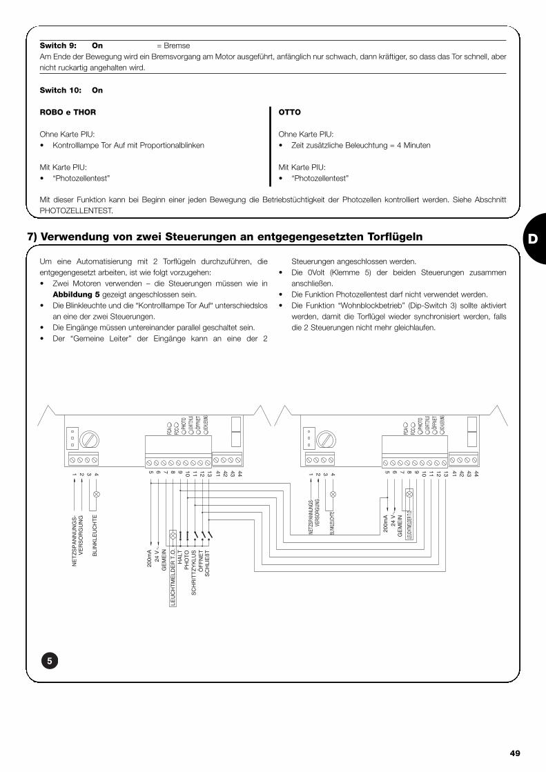
D
49
Switch 9: On = BremseAm Ende der Bewegung wird ein Bremsvorgang am Motor ausgeführt, anfänglich nur schwach, dann kräftiger, so dass das Tor schnell, abernicht ruckartig angehalten wird.
Mit dieser Funktion kann bei Beginn einer jeden Bewegung die Betriebstüchtigkeit der Photozellen kontrolliert werden. Siehe AbschnittPHOTOZELLENTEST.
Um eine Automatisierung mit 2 Torflügeln durchzuführen, dieentgegengesetzt arbeiten, ist wie folgt vorzugehen:• Zwei Motoren verwenden – die Steuerungen müssen wie in
Abbildung 5 gezeigt angeschlossen sein.• Die Blinkleuchte und die “Kontrolllampe Tor Auf“ unterschiedslos
an eine der zwei Steuerungen.• Die Eingänge müssen untereinander parallel geschaltet sein.• Der “Gemeine Leiter” der Eingänge kann an eine der 2
Steuerungen angeschlossen werden.• Die 0Volt (Klemme 5) der beiden Steuerungen zusammen
anschließen.• Die Funktion Photozellentest darf nicht verwendet werden.• Die Funktion “Wohnblockbetrieb” (Dip-Switch 3) sollte aktiviert
werden, damit die Torflügel wieder synchronisiert werden, fallsdie 2 Steuerungen nicht mehr gleichlaufen.
7) Verwendung von zwei Steuerungen an entgegengesetzten Torflügeln
Switch 10: On
ROBO e THOR
Ohne Karte PIU:• Kontrolllampe Tor Auf mit Proportionalblinken
Mit Karte PIU:• “Photozellentest”
OTTO
Ohne Karte PIU:• Zeit zusätzliche Beleuchtung = 4 Minuten
Mit Karte PIU:• “Photozellentest”
5

50
Karte PIUDie Steuerung enthält bereits alle Funktionen, die in einer normalen Installation verwendet werden; um den Erforderungen besondererAnlagen gerecht zu werden, wurde die Sonderkarte “PIU” vorbereitet, mit der neue Funktionen wie Ampel, zusätzliche Beleuchtung, Elek-troschloss, Photo2, Teilöffnung und Photozellentest hinzugefügt werden können.
Rot = rotes Licht der AmpelGewöhnlich immer abgeschaltet, schaltet sichdas rote Licht während der Torbewegung ein.
Grün = grünes Licht der AmpelGewöhnlich eingeschaltet, schaltet sich dasgrüne Licht während der Torbewegung ab.
Elektroschloss = Ausgang für Elektroschloss.Das Elektroschloss wird am Anfang derBewegung in Öffnung für 1,5 Sekunden aktiviert.
Zusätzliche Beleuchtung/ Photozellentest = Wenn dieser Ausgang für die zusätzliche
Beleuchtung benutzt wird, wird sich am Beginnjeder Bewegung eine zusätzliche Beleuchtungeinschalten, die bis nach Ende der Bewegungund je nach Zeit, die am Trimmer T.Cor. auf derKarte “PIU” programmiert wird, eingeschaltetbleibt. Wenn man die Funktion Photozellentestaktiviert (Dip-Switch10=ON), so wird es dieser
Ausgang ermöglichen, einen Test derPhotozellen bei Bewegungsbeginn auszuführen.
Teil-Öffnung = Eingang für Teilöffnung (Teilw. Auf, Stop, Zu,Stop). Führt die gleiche Funktion wieSchrittbetrieb an der Hauptkarte aus, mit demUnterschied, dass die Bewegung in Öffnung dieam Trimmer T.AP.P. der Karte “PIU” eingestellteZeit dauert.
Foto 2 = Eingang 2. Sicherheitsvorrichtung. DieseSicherheitsvorrichtung spricht nur bei derBewegung in Öffnung an und verursacht einStop der Bewegungen mit eventuellemWiederschließen, falls die “Halbautomatische”oder die “Automatische” Betriebsart an derSteuerung programmiert ist.
24 V = 24V Ausgang, für die Versorgung vonNebenvorrichtungen wie Photozellen oderanderes verwendbar. Die Klemme 11 ist auchder Gemeine Leiter der Eingänge.
Karte RADIOAn der Steuerung befindet sich ein Verbinder für das Einstecken einer von Nice hergestellten Radiokarte, über die der Eingang SCHRTT-BETRIEB betätigt werden kann, wodurch die Steuerung über einen Sender ferngesteuert wird.
8) Sonderzubehör
Die Steuerung, ein elektronischer Teil, ist praktisch wartungsfrei;trotzdem sollte die Effizienz und die Einstellung der Regelvorrichtungder Motorkraft regelmäßig (mindestens alle 6 Monate) überprüftwerden, wobei gegebenenfalls die Einstell-Trimmer zu betätigensind.
Die in Prüfung verzeichneten Schritte nochmals durchführen, um dieEffizienz der Endschalter und der Sicherheitsvorrichtungen(Photozellen, Sicherheitsleisten, usw.) und den korrekten Betrieb derBlinkleuchte zu kontrollieren.
9) Wartung
Dieses Produkt besteht aus verschiedenen Werkstoffen, von deneneinige wiederverwertet werden können.Informieren Sie sich über die Recycling- oder Entsorgungsmethodenund halten Sie sich strikt an die örtlich gültigen Bestimmungen.
Bestimmte elektronische Komponenten könntenumweltverschmutzende Substanzen enthalten – nicht indie Umwelt geben!
!
10) Entsorgung
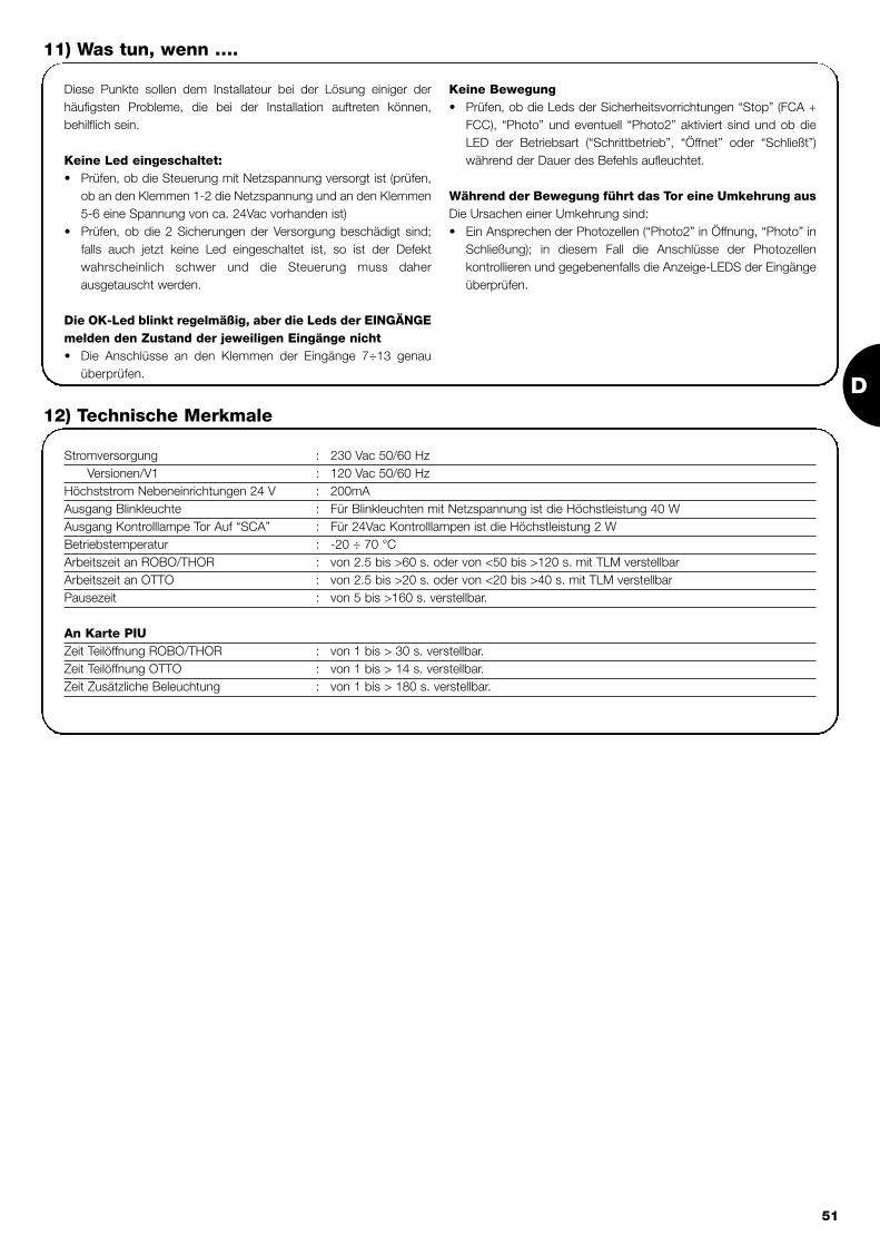
D
51
Diese Punkte sollen dem Installateur bei der Lösung einiger derhäufigsten Probleme, die bei der Installation auftreten können,behilflich sein.
Keine Led eingeschaltet:• Prüfen, ob die Steuerung mit Netzspannung versorgt ist (prüfen,
ob an den Klemmen 1-2 die Netzspannung und an den Klemmen5-6 eine Spannung von ca. 24Vac vorhanden ist)
• Prüfen, ob die 2 Sicherungen der Versorgung beschädigt sind;falls auch jetzt keine Led eingeschaltet ist, so ist der Defektwahrscheinlich schwer und die Steuerung muss daherausgetauscht werden.
Die OK-Led blinkt regelmäßig, aber die Leds der EINGÄNGEmelden den Zustand der jeweiligen Eingänge nicht• Die Anschlüsse an den Klemmen der Eingänge 7÷13 genau
überprüfen.
Keine Bewegung• Prüfen, ob die Leds der Sicherheitsvorrichtungen “Stop” (FCA +
FCC), “Photo” und eventuell “Photo2” aktiviert sind und ob dieLED der Betriebsart (“Schrittbetrieb”, “Öffnet” oder “Schließt”)während der Dauer des Befehls aufleuchtet.
Während der Bewegung führt das Tor eine Umkehrung ausDie Ursachen einer Umkehrung sind: • Ein Ansprechen der Photozellen (“Photo2” in Öffnung, “Photo” in
Schließung); in diesem Fall die Anschlüsse der Photozellenkontrollieren und gegebenenfalls die Anzeige-LEDS der Eingängeüberprüfen.
11) Was tun, wenn ….
Stromversorgung : 230 Vac 50/60 HzVersionen/V1 : 120 Vac 50/60 Hz
Höchststrom Nebeneinrichtungen 24 V : 200mAAusgang Blinkleuchte : Für Blinkleuchten mit Netzspannung ist die Höchstleistung 40 WAusgang Kontrolllampe Tor Auf “SCA” : Für 24Vac Kontrolllampen ist die Höchstleistung 2 W Betriebstemperatur : -20 ÷ 70 °CArbeitszeit an ROBO/THOR : von 2.5 bis >60 s. oder von <50 bis >120 s. mit TLM verstellbarArbeitszeit an OTTO : von 2.5 bis >20 s. oder von <20 bis >40 s. mit TLM verstellbarPausezeit : von 5 bis >160 s. verstellbar.
An Karte PIUZeit Teilöffnung ROBO/THOR : von 1 bis > 30 s. verstellbar.Zeit Teilöffnung OTTO : von 1 bis > 14 s. verstellbar.Zeit Zusätzliche Beleuchtung : von 1 bis > 180 s. verstellbar.
12) Technische Merkmale

52
central de mando motorreductores robo, thor, otto
Advertencias:
Este manual está destinado sólo al personal técnicocualificado para la instalación.Ninguna información contenida en este manual puede serconsiderada de interés para el usuario final.Este manual se refiere sólo a esta central y no se debeemplear para otros productos.Se aconseja leer con atención, una vez como mínimo, todas lasinstrucciones antes de proceder con la instalación.
!
Indice: pág.
1 Descripción del producto 53
2 Instalación 542.1 Instalación típica 542.2 Conexiones eléctricas 542.2.1 Esquema eléctrico 552.2.2 Descripción de las conexiones 552.2.3 Fototest 562.2.4 Control de las conexiones 57
3 Regulaciones 57
4 Ensayo 58
5 Modos de funcionamiento 59
pág.
6 Funciones programables 596.1 Descripción de las funciones 60
7 Empleo de dos centrales en hojas 61contrapuestas
8 Accesorios opcionales 62
9 Mantenimiento 62
10 Desguace 62
11 Qué hay que hacer si… 63
12 Características técnicas 63

E
53
1) Descripción del productoEsta central para la automatización de cancelas o puertasautomáticas permite accionar los actuadores ROBO, OTTO, THORde corriente alterna monofásica.De acuerdo con el tipo de actuador que se ha de accionar, la centraltiene variantes, tales como: “Regulación de Fuerza”, “Indicadorluminoso Cancela Abierta” y “Luz de cortesía”.Además, cuenta con una serie de funciones que se seleccionan pormedio de los “Dip-Switches” (mini-selectores) y regulaciones que serealizan con los trimmers.
En la central hay leds situados cerca de las entradas que indican elestado; otro led, colocado cerca del microprocesador, indica que lalógica interior funciona correctamente.
Para reconocer más fácil las piezas en la fig.1 se muestran loscomponentes más importantes.
LMNOP
J
QRST
V U
I
X
W
YHG
FZ
EDCBA
CH
P.P.
AP
FOTO
FCA
FCCOK
Dip-Switch de selección de las funcionesTrimmer de regulación FuerzaTrimmer de regulación Tiempo Funcionamiento TLTrimmer de regulación Tiempo Pausa TPCaja de conexiones para la antena y 2° canalConexión tarjeta RADIOLed de indicación del estado de las entradasCaja de conexiones Entradas / Salidas de mandoRelé ComúnCaja de conexiones alimentación / Luz intermitenteConector primario del transformadorFusible de línea (5A)Conector de salida de la Luz de Cortesía (sólo en OTTO)Salida alimentación motorConector del condensadorRelé “Punto de arranque”Triac “Luz de cortesía” (sólo en OTTO)Triac “Cerrar”Triac “Abrir”Conector secundario del transformadorEntrada fin de carrera FCA / FCCFusible de baja tensión (500mA)Conexión tarjeta PIULed OKMicroprocesador
ABCDEFGHIJLMNOPQRSTUVWXYZ
1
Código Producto* Código Central de mando* Función Adicional
ROBORO1000RO1020
ROA3 Trimmer de “Regulación Fuerza”
RO1010 ROA4 Relé “Punto de arranque”
THOR TH1551 THA5 Trimmer de “Regulación Fuerza”TH2251 THA6 Relé “Punto de arranque”
OTTO OT21 OTA1 Salida “Luz de cortesía”
* = añadir al código V1 para versión 120 V 50/60 Hz

54
2.1) Instalación típica
A fin de aclarar algunos términos y algunos aspectos de una instalación de automatización para puertas o cancelas, damos un ejemplo típico.
ROBO / THOR OTTO
1) Par de fotocélulas “Fotocélula”2) Luz intermitente3) Selector de llave4) Borde neumático5) Par de fotocélulas “Fotocélula 2”
Recordamos en particular que:• Todas las fotocélulas fabricadas por NICE disponen del sistema de Sincronismo, que permite eliminar el problema de la interferencia
entre dos pares de fotocélulas (para mayores aclaraciones véanse las instrucciones de las fotocélulas).• El par de fotocélulas “Fotocélula” en apertura no tiene efecto, mientras que provoca una inversión durante el cierre.• El par de fotocélulas “Fotocélula 2” durante el cierre no tiene efecto mientras que provoca una inversión durante la apertura.
Recuerde que los sistemas de cancelas y puertasautomáticas tienen que ser instalados sólo por personaltécnico cualificado y respetando las normas vigentes.
Siga con atención las advertencias del fascículo:“Advertencias para el instalador”.
!
2) Instalación
2a 2b
2.2) Conexiones eléctricas
Para garantizar la seguridad del instalador y no averiarlos componentes, mientras se efectúan las conexioneseléctricas, o se conectan las distintas tarjetas, la centraldebe estar completamente apagada.
• Alimente la central con un cable de 5 x 1,5mm2; si la distanciaentre la central y la conexión a la instalación de tierra es superiora 30 m, hay que instalar una placa de conexión a tierra cerca dela central.
• En las conexiones de las piezas de baja tensión de seguridaduse cables de sección mínima de 0,25mm2.
• Use cables de conductores encerrados si la longitud es superiora 30m, conectando la trenza de masa sólo del lado de la central.
• No conecte los cables en cajas enterradas aún si sonherméticas.
• Las entradas de los contactos tipo Normalmente Cerrado (NC)que no se utilicen se tienen que conectar al "Común 24V " pormedio de un conector puente, excluidas las entradas de las
fotocélulas si la función fototest está conectada; para másaclaraciones véase el párrafo “Fototest”.
• Si para la misma entrada hay varios contactos NC, se debenconectar en “Serie” entre sí.
• Si las entradas de los contactos tipo Normalmente Abierto (NA)no se utilizan, se tiene que dejar libres.
• Si para la misma entrada hay varios contactos NA se conectanen “Parallelo” entre sí.
• Los contactos tienen que ser exclusivamente mecánicos y sinningún potencial; no se admiten conexiones de configuracióncomo aquéllas definidas “PNP”, “NPN”, “Open Collector”, etc.
!

E
55
2.2.1) Esquema eléctrico
2.2.2) Descripción de las conexiones
Damos una descripción breve de las posibles conexiones de la central hacia el exterior.
Bornes Funciones Descripción
1-2 : Alimentación = Línea de alimentación de red
3-4 : Luz intermitente = Salida para la conexión de la luz intermitente con tensión de red (máx. 40W)
5-6 : 24 Vca = Alimentación de los equipos auxiliares 24 Vca (Fotocélula, Radio, etc.) Máx 200mA
7 : Común = Común para todas las entradas
8 : Indicador luminoso C.A = Indicador luminoso cancela abierta 24 Vca máx. 2W (no instalado en la versión OTTO)
9 : Stop = Entrada con función de parada de la maniobra e inversión breve del movimiento
10 : Fotocélula = Entrada para los dispositivos de seguridad (Fotocélulas, bordes neumáticos)
11 : Paso a Paso (PP) = Entrada para el funcionamiento cíclico ("Abrir" - "Stop" - "Cerrar" - "Stop")
12 : Abrir = Entrada para el movimiento de apertura
13 : Cerrar = Entrada para el movimiento de cierre
41-42 : 2° Canal Radio = Salida del posible segundo canal del radiorreceptor
43-44 : Antena = Entrada para la antena del radiorreceptor
3

56
2.2.3) Fototest
“Fototest” es una óptima solución en términos de fiabilidad para losdispositivos de seguridad, permite lograr la “categoría 2” según la normaUNI EN 954-1 (edic. 12/1998) respecto del grupo central y fotocélulasde seguridad.Cada vez que se acciona una maniobra, son controlados todos losdispositivos de seguridad implicados y la maniobra comienza sólo sitodo está en perfectas condiciones. Si en cambio la prueba no daresultado positivo (fotocélula encandilada por el sol, cables encortocircuito, etc.) se detecta la avería y la maniobra no se realiza.
Para obtener la función “Fototest” es necesario:• Utilizar la tarjeta adicional “PIU”.• Configurar el Dip-Switch 10 en ON .• Realizar una configuración especial en las conexiones de los
dispositivos de seguridad, como muestra la fig. 4a, que prevéla conexión de la alimentación de los transmisores de lasfotocélulas no directamente a la salida de los equipos auxiliares,sino que cortando dicha alimentación pasando por los bornes 7y 8 de la tarjeta PIU. La corriente máxima que se utiliza en elsalida “Fototest” de la tarjeta “PIU” es 100mA (2 pares defotocélulas Nice).
• Alimentar los receptores directamente desde la salida de losequipos auxiliares de la central (bornes 5-6).
Si en un segundo momento no se desea utilizar más la función
“Fototest”, habrá que bajar el Dip-Switch 10 y modificar la configuración de
las conexiones, como muestra la fig. 4b.
El ensayo de las fotocélulas se realiza del siguiente modo: cuandose requiere un movimiento, en primer lugar se controla que todos losreceptores implicados en el movimiento den el asenso; luego, seapaga la alimentación a los transmisores y se controla que todos losreceptores señalen el hecho cortando el asenso; por último, sereactiva la alimentación de los transmisores y se controlanuevamente el asenso por parte de todos los receptores. Sólo siesta secuencia da resultado positivo, la maniobra iniciará.Además, se aconseja activar el sincronismo cortando las conexionespuente en los transmisores; este es el único modo para garantizarque dos pares de fotocélulas no interfieran entre sí. Controle en elmanual de las fotocélulas las instrucciones para el funcionamiento"Sincronizado".
Si una entrada sujeta a “Fototest” no se utilizara (ejemplo“Fotocélula2”) e igualmente desea la función fototest, hay queconectar con un conector puente la entrada no utilizada, comoindicado en la fig. 4c.
“Fotocélula” y “Fotocélula2” con “Fototest”
“Fotocélula” y “Fotocélula2” sin “Fototest”
“Fotocélula” con “Fototest”
4a
4b
4c

E
57
2.2.4) Control de las conexiones
Las siguientes operaciones se efectúan con los circuitos bajotensión; la mayoría de los circuitos está a muy baja tensión deseguridad y, por ello, no son peligrosos; algunas piezas están bajotensión de red, es decir, “MUY PELIGROSAS”! Tenga muchocuidado en lo que está haciendo y NUNCA TRABAJE SÓLO!
• Alimente la central y controle de inmediato que entre los bornes5-6 haya una tensión de 24 Vca.
• Controle que, después de un parpadeo rápido, el led “OK”parpadee con una cadencia regular.
• Entonces, controle que los leds que corresponden a las entradascon contactos tipo NC estén encendidos (todos los dispositivosde seguridad accionados) y que los leds que corresponden a lasentradas con contactos tipo NA estén apagados (ningúnaccionamiento activo); si esto no se produce, controle lasconexiones y que todos los dispositivos funcionen correctamente.la entrada STOP se acciona apagando FCA y FCC.
• Controle que los fines de carrera estén bien conectados; muevala palanca del fin de carrera y controle que el fin de carreracorrespondiente se accione, apagando el led respectivo en lacentral.
• Desbloquee la hoja y colóquela a la mitad de la carrera, luegobloquéela para que se pueda abrir o cerrar libremente.
• Entonces, controle si el movimiento se efectúa en la direccióncorrecta, es decir, controle que el movimiento previsto por lacentral y aquél efectivo de las hojas correspondan. Este controles fundamental; si la dirección es incorrecta, en algunos casos(por ejemplo en modo “semiautomático”) la automatización
aparentemente podría funcionar regularmente; en efecto, el ciclo“Abrir” es parecido al ciclo “Cerrar” con la diferencia fundamentalde que los dispositivos de seguridad son ignorados en lamaniobra de cierre, la cual es generalmente más peligrosa, y seaccionarán durante la apertura provocando un cierre sobre elobstáculo con resultados desastrosos.
• Para controlar si el sentido de rotación es correcto, es suficientedar un breve impulso en la entrada Paso a Paso (PP); la primeramaniobra que la central efectúa tras haber sido accionadasiempre es Abrir, luego es suficiente controlar si laautomatización se abre; por último, si el movimiento se haefectuado en el sentido incorrecto es necesario:
� Apagar la alimentación� Girar 180° el conector de alimentación del motor y el delos fines de carrera (Ref. “O” y Ref. “V” de Fig.1)� Una vez efectuado cuanto descrito, conviene probarnuevamente si el sentido de rotación es correcto, repitiendo elúltimo punto.
El led “OK”, situado en el centro de la tarjeta, tiene la función de
señalar el estado de la lógica interior: un parpadeo regular cada 1 segundo
indica que el microprocesador interior está activo y espera el mando. En
cambio, cuando el microprocesador reconoce una variación del estado de
una entrada (bien de una entrada de mando o de un Dip-Switch de las
funciones) produce un parpadeo doble rápido, incluso si la variación no
provoca efectos inmediatos. Un parpadeo rápido de 3 s. indica que la central
se ha apenas encendido y está realizando un ensayo de las piezas internas;
por último un parpadeo inconstante indica que el ensayo no tuvo resultados
positivos y, por consiguiente, hay una avería.
!
Las regulaciones se efectúan con los trimmers que actúanmodificando los siguientes parámetros:
Tiempo Funcionamiento (TL): Regula la duración máxima de la maniobra de apertura o cierre.
Para regular el tiempo de funcionamiento TL, seleccione el modo defuncionamiento “Semiautomático” desplazando hacia ON el Dip-Switch 1 y luego regule el trimmer TL a la mitad de la carrera. Condichas regulaciones realice un ciclo de apertura y de cierre; si fueranecesario, actúe sobre la regulación del trimmer TL de manera quesea suficiente para cumplir toda la maniobra y que todavía quede unmargen de 2 ó 3 s..Si colocando el trimmer TL al máximo no se obtiene un tiemposuficiente, corte el conector puente TLM, colocado en el circuitoimpreso entre los trimmers TL y TP, para obtener un tiempo deFuncionamiento mayor.
Tiempo Pausa (TP):En el funcionamiento “automático” regula el tiempo entre el final dela maniobra de apertura y el comienzo de la maniobra de cierre.
Para regular el Tiempo Pausa TP, seleccione el modo defuncionamiento “Automático” desplazando hacia ON el Dip-Switch 2,luego regule el trimmer TP a placer. Para el control, ejecute unamaniobra de apertura y controle el tiempo que transcurre antes delcierre “Automático”.
Fuerza (F): Instalada en la central para el accionamiento, permite regular el valorde la “Fuerza” máxima.
Preste mucha atención cuando regule el trimmer “Fuerza” (F),puesto que puede influir sobre el grado de seguridad de laautomatización. Para la regulación hay que actuar por tentativassucesivas, midiendo la fuerza aplicada a la hoja y comparándola concuanto previsto por las normas.
En las centrales RO1010 y OT21 la “Fuerza” se regula con un selectorde varias posiciones, situado en la caja del transformador dealimentación de la central.
3) Regulaciones
TPTLF
TLM

58
Finalizados los controles y regulaciones es posible efectuar el ensayo de la instalación.
El ensayo de la automatización tiene que ser efectuado por personal cualificado y experto que deberá establecer losensayos previstos de acuerdo con el riesgo presente.
El ensayo es la parte más importante de toda la etapa de realización de la automatización. Cada componente, por ejemplo motor, dispositivode parada de emergencia, fotocélulas, etc. puede requerir un ensayo específico; por consiguiente, se aconseja seguir los procedimientosindicados en los manuales de instrucciones respectivos.
Para el ensayo de la central ejecute el siguiente procedimiento:
1. Seleccione las funciones: • Configure en ON el Dip-Switch 1 (Funcionamiento “semiautomático”)• Si no se han realizado las conexiones de la fig.4a para el uso de la función “Fototest” (si está instalada la tarjeta PIU), configure en
ON el Dip-Switch 10 (Función “fototest”).• Configure en OFF todos los demás Dip-Switches
2. Oprima el botón de mando “Abrir” o “Paso a Paso” y compruebe que:• se active la luz intermitente• empiece una maniobra de apertura • el movimiento se detenga al alcanzar el fin de carrera de apertura FCA.
3. Oprima el botón de mando “Cerrar” o “Paso a Paso” y compruebe que:• se active la luz intermitente• empiece una maniobra de cierre• el movimiento se detenga al alcanzar el fin de carrera de cierre FCC
4. Haga iniciar una maniobra de apertura y controle que durante la maniobra, el accionamiento de un dispositivo:• conectado a la entrada “Stop”, provoca la parada con una inversión breve del movimiento• conectado a la entrada “Fotocélula”, no tenga ningún efecto • conectado a la entrada “Fotocélula2”, provoque la parada y la inversión de la maniobra (si está instalada la tarjeta PIU).
5. Haga iniciar una maniobra de cierre y controle que durante la maniobra, el accionamiento de un dispositivo:• conectado a la entrada “Stop”, provoca la parada con una inversión breve del movimiento• conectado a la entrada “Fotocélula”, provoque la parada y la inversión de la maniobra• conectado a la entrada “Fotocélula2”, no tenga ningún efecto (si está instalada la tarjeta PIU).
6. En las entradas conectadas, controle que la activación de la entrada provoque un paso en la secuencia:• Entrada Paso a Paso: Secuencia = “Abrir” – “Stop” – “Cerrar” – “Stop”• Entrada Abrir: Secuencia = “Abrir” – “Stop” – “Abrir” – “Stop”• Entrada Cerrar: Secuencia = “Cerrar” – “Stop” - “Cerrar” – “Stop”• Entrada Abrir Parcial: Secuencia = “Abrir Parcial” – “Stop” – “Cerrar” – Stop” (si está instalada la tarjeta PIU).
7 Si se utiliza la función fototest, controle la eficiencia del ensayo (si está instalada la tarjeta PIU):• Cubra la fotocélula "Fotocélula", haga iniciar una maniobra y controle que dicha maniobra no arranque • Cubra la fotocélula "Fotocélula2", haga iniciar una maniobra y controle que dicha maniobra no arranque• Realice un cortocircuito en el contacto de la fotocélula "Fotocélula", haga iniciar una maniobra y controle que dicha maniobra no arranque• Realice un cortocircuito en el contacto de la fotocélula "Fotocélula2", haga iniciar una maniobra y controle que dicha maniobra no arranque
8. Realice los ensayos para medir las “Fuerzas de Impacto”, como previsto por la norma EN 12445.
Si al final del ensayo se activan otras funciones que puedan reducir la seguridad de la instalación, es necesario efectuar el ensayo específicode dichas funciones.
!
4) Ensayo

E
59
5) Modos de funcionamiento
En el funcionamiento en modo manual la entrada “Abrir” permite elmovimiento de apertura y la entrada “Cerrar” permite el movimientode cierre. El “Paso a Paso” permite el movimiento de apertura ycierre alternativamente.Ni bien cesa el mando de entrada el movimiento se detiene. Durantela apertura el movimiento se detiene cuando se accionan los fines decarrera, o bien si falta el permiso de la “Fotocélula 2” (en la tarjetaPIU); en cambio, durante el cierre, el movimiento se detiene si faltael asenso de “Fotocélula”. El accionamiento de “Stop” provoca unaparada inmediata del movimiento tanto durante la apertura comodurante el cierre. Cuando el movimiento se detiene, deje de accionarel mando en entrada antes de poder iniciar con un nuevomovimiento.Durante el funcionamiento en uno de los dos modos automáticos(“Semiautomático”, “Automático” o “Cerrar Siempre”) un impulso deaccionamiento en la entrada “Abrir” provoca el movimiento deapertura. Un impulso sobre “Paso a Paso” provoca la apertura o elcierre alternativamente. Un segundo impulso sobre “Paso a Paso”,
o sobre la misma entrada que ha comenzado el movimiento,provoca un Stop.El accionamiento de “Stop” provoca una parada inmediata delmovimiento, tanto durante la apertura como durante el cierre.Si en una entrada de mando en vez de un impulso se mantiene unaseñal continua, se provoca un estado de “preponderancia” en el cuallas demás entradas quedan desactivadas (útil para conectar unreloj o un selector Noche-Día).Si se selecciona el modo de funcionamiento automático, tras unamaniobra de apertura, se efectúa una pausa y luego el cierre. Sidurante la pausa se acciona “Fotocélula” el temporizador serestablecerá con un nuevo tiempo de pausa; si en cambio durantela pausa se acciona “Stop”, la función de cierre se pone a cero y sepasa a un estado de “ Stop”. Durante la apertura el accionamientode “Fotocélula” no tiene ningún efecto, mientras que la “Fotocélula2”(en la tarjeta PIU) provoca la inversión del movimiento; durante elcierre, el accionamiento de “Fotocélula” provoca una inversión delmovimiento, luego una pausa y finalmente un nuevo cierre.
La central dispone de una serie de microinterruptores que permitenactivar varias funciones para que la instalación sea más adecuada alas exigencias del usuario y más segura en cualquier condición deempleo. Todas las funciones se activan poniendo el respectivo Dip-Switch en la posición “On”, mientras que con el Dip-Switchcorrespondiente en “Off” no están activas.
Algunas de las funciones programables estánvinculadas con aspectos de la seguridad; evalúe conmucha atención los efectos de una función y verifiquecuál es la función que brinde la mayor seguridad posible.
!
Los Dip-Switches permiten seleccionar los diferentes modos de funcionamiento e introducir las funciones deseadas según la siguiente tabla:
Switch 1-2: Off-Off = Movimiento “Manual”, es decir Pulsador de interrupción automáticaOn -Off = Movimiento “Semiautomático”Off-On = Movimiento “Automático”, es decir cierre automáticoOn -On = Movimiento “Automático + Cerrar Siempre”
Switch 3: On = Funcionamiento Comunitario < no disponible en modo manual >Switch 4: On = Parpadeo previoSwitch 5: On = Cierra 5 s. después de Fotocélula < si está en “Automático”> o Cierra después de “Fotocélula”
< si está en “Semiautomático”>Switch 6: On = Dispositivo de seguridad “Fotocélula” también durante aperturaSwitch 7: On = Arranque gradualSwitch 8: On = DeceleraciónSwitch 9: On = FrenoSwitch 10: (en Robo) On = Indicador luminoso C.A. con parpadeo proporcional
Sin tarjeta PIU(en Otto) On = Tiempo luz de cortesía = 4 minutos
Con tarjeta PIU On = Función “Fototest”
NOTA: algunas funciones son posibles en determinadas condiciones que se señalan con las notas entre los signos “<...>”.
6) Funciones programables
101

60
6.1) Descripción de las funcionesA continuación, damos una breve descripción de las funciones que se pueden introducir colocando en “On” el Dip-Switch correspondiente.
Switch 1-2: Off-Off = Movimiento “Manual” (Pulsador de interrupción automática)On-Off = Movimiento “Semiautomático”Off-On = Movimiento “Automático” (cierre automático)On-On = Movimiento “Automático + Cerrar siempre”
Durante el funcionamiento “Manual” el movimiento se efectúa sólo hasta que se acciona el mando (botón apretado).En modo “Semiautomático” es suficiente dar un impulso de mando para que se cumpla todo el movimiento, hasta que termina el TiempoFuncionamiento o alcanzar el fin de carrera. En el funcionamiento en modo “Automático”, después de la apertura, se efectúa una pausa yluego un cierre automático. La función “Cerrar Siempre” se acciona tras un corte de alimentación, si detecta que la cancela está abierta, sepone en marcha automáticamente una maniobra de cierre, antecedida por 5 segundos de parpadeo previo.
Switch 3: On = Funcionamiento comunitario (no disponible en modo Manual)Durante el funcionamiento comunitario, una vez que se puso en marcha un movimiento de apertura, la maniobra no puede ser interrumpidapor otros impulsos de mando en “Paso a Paso” o “Abrir”, hasta que no finalice el movimiento de apertura. Durante el movimiento de cierre,al efectuar un nuevo accionamiento, se produce la parada y la inversión del movimiento y se abre nuevamente.
Switch 4: On = Parpadeo previoAl recibir el impulso de mando, primero se activa la luz intermitente, luego, transcurridos 5 s. (2 s. si está en modo “manual”) inicia elmovimiento.
Switch 5: On = Cierra 5 s.s después de “Fotocélula” < si está en “Automático” > o Cierra después de “Fotocélula” < si está en “Semiautomático” >
Esta función, si está en ciclo automático, permite mantener la cancela abierta sólo por el tiempo necesario para el paso; en efecto, despuésde la activación de Fotocélula la maniobra se detiene. Después de 5 s., arrancará automáticamente una maniobra de cierre. Si está en ciclosemiautomático, un accionamiento de fotocélula en la maniobra de cierre activa el cierre automático con el tiempo de pausa regulado.
Switch 6: On = Dispositivo de seguridad (“Fotocélula”) también durante aperturaNormalmente, el dispositivo de seguridad “Fotocélula” está activo sólo durante la maniobra de cierre, si el Dip-Switch 6 se coloca en "On"el accionamiento del dispositivo de seguridad provoca una interrupción del movimiento también durante la apertura.Si está en “Semiautomático” o “Automático”, el movimiento de apertura se reanudará inmediatamente después de la desconexión.
Switch 7: On = Arranque gradualEjecuta el arranque gradual del movimiento evitando sacudidas indeseables de la automatización.
Switch 8: On = Deceleración La deceleración consiste en una disminución de la velocidad del 30% de la velocidad nominal, para evitar sacudidas inútiles al final de lamaniobra.
La función de deceleración, además de disminuir la velocidad de la automatización, disminuye un 70% el par del motor.
En automatizaciones que requieren un par elevado, dicha disminución podría provocar la parada inmediata del motor.
Versión ROBO / THOR:Al terminar la maniobra de apertura o cierre, por la conclusión delTiempo Funcionamiento, se efectúa una deceleración que duratanto cuanto el Tiempo de Trabajo.Si la maniobra concluye porque se accionó el fin de carrera, ladeceleración no se ejecuta, entonces hay que regular el TiempoFuncionamiento para que comience a decelerar 30-50 cm antes delaccionamiento de los fines de carrera.
Versión OTTO:Al terminar la maniobra de cierre, la etapa de deceleración dura 3 s.,si es activada por el accionamiento de los fines de carrera; cuanto elTL si es activada por el final del Tiempo Funcionamiento (para unbuen funcionamiento de la deceleración se aconseja usar los finesde carrera).En la maniobra de apertura no se produce la deceleración, sino unaparada gradual.
Si no se utiliza la función de deceleración eninstalaciones sensibles, y si esta dura más de 3 segundos,hay que introducir en los bornes de alimentación de red,situados cerca de la central, un filtro de red de 6A como
! mínimo, con atenuación de 30 dB para no superar loslímites de emisión electromagnética indicados en lanorma EN 50081-1.

E
61
Switch 9: On = FrenoAl final del movimiento se ejecuta un procedimiento de freno en el motor: primero suave y luego más intenso, para detener la cancelarápidamente pero sin sacudidas.
Esta función permite efectuar un control de la eficiencia de las fotocélulas cada vez que comienza una maniobra. Véase el capítulo“Fototest”.
Para realizar una automatización con 2 hojas que trabajan demanera contrapuesta, siga estos pasos:• Use dos motores con las centrales conectadas como indicado
en la fig. 5.• Conecte la luz intermitente y el Indicador luminoso Cancela
Abierta a una de las dos centrales indistintamente.• Las entradas deben estar paralelas entre sí. • El “Común” de las entradas se puede conectar a una de las 2
centrales.• Conecte juntos los 0Voltios (Borne 5) de las dos centrales.• No se debe utilizar la función “Fototest”.• Es oportuno conectar la función "Comunitaria" (Dip-Switch 3),
puesto que permite sincronizar las hojas en el caso de que lasdos centrales perdieran la sincronización.
7) Empleo de dos centrales en hojas contrapuestas
Switch 10: On
ROBO e THOR
Sin tarjeta PIU conectada• Indicador luminoso C.A. con parpadeo proporcional
Con tarjeta PIU conectada• “Fototest”
OTTO
Sin tarjeta PIU conectada• Tiempo luz de cortesía = 4 minutos
Con tarjeta PIU conectada• “Fototest”
5
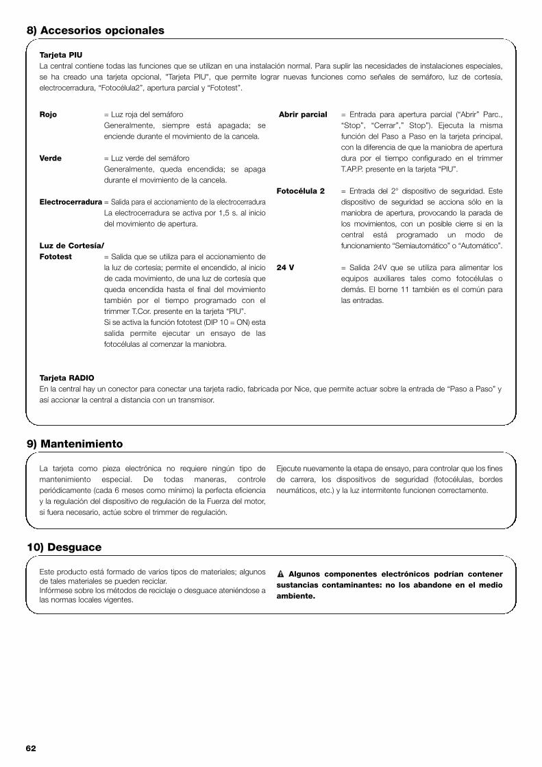
62
Tarjeta PIULa central contiene todas las funciones que se utilizan en una instalación normal. Para suplir las necesidades de instalaciones especiales,se ha creado una tarjeta opcional, "Tarjeta PIU", que permite lograr nuevas funciones como señales de semáforo, luz de cortesía,electrocerradura, “Fotocélula2”, apertura parcial y “Fototest”.
Rojo = Luz roja del semáforoGeneralmente, siempre está apagada; seenciende durante el movimiento de la cancela.
Verde = Luz verde del semáforoGeneralmente, queda encendida; se apagadurante el movimiento de la cancela.
Electrocerradura = Salida para el accionamiento de la electrocerraduraLa electrocerradura se activa por 1,5 s. al iniciodel movimiento de apertura.
Luz de Cortesía/ Fototest = Salida que se utiliza para el accionamiento de
la luz de cortesía; permite el encendido, al iniciode cada movimiento, de una luz de cortesía quequeda encendida hasta el final del movimientotambién por el tiempo programado con eltrimmer T.Cor. presente en la tarjeta “PIU”.Si se activa la función fototest (DIP 10 = ON) estasalida permite ejecutar un ensayo de lasfotocélulas al comenzar la maniobra.
Abrir parcial = Entrada para apertura parcial (“Abrir” Parc.,“Stop”, “Cerrar”,” Stop”). Ejecuta la mismafunción del Paso a Paso en la tarjeta principal,con la diferencia de que la maniobra de aperturadura por el tiempo configurado en el trimmerT.AP.P. presente en la tarjeta “PIU”.
Fotocélula 2 = Entrada del 2° dispositivo de seguridad. Estedispositivo de seguridad se acciona sólo en lamaniobra de apertura, provocando la parada delos movimientos, con un posible cierre si en lacentral está programado un modo defuncionamiento “Semiautomático” o “Automático”.
24 V = Salida 24V que se utiliza para alimentar losequipos auxiliares tales como fotocélulas odemás. El borne 11 también es el común paralas entradas.
Tarjeta RADIOEn la central hay un conector para conectar una tarjeta radio, fabricada por Nice, que permite actuar sobre la entrada de “Paso a Paso” yasí accionar la central a distancia con un transmisor.
8) Accesorios opcionales
La tarjeta como pieza electrónica no requiere ningún tipo demantenimiento especial. De todas maneras, controleperiódicamente (cada 6 meses como mínimo) la perfecta eficienciay la regulación del dispositivo de regulación de la Fuerza del motor,si fuera necesario, actúe sobre el trimmer de regulación.
Ejecute nuevamente la etapa de ensayo, para controlar que los finesde carrera, los dispositivos de seguridad (fotocélulas, bordesneumáticos, etc.) y la luz intermitente funcionen correctamente.
9) Mantenimiento
Este producto está formado de varios tipos de materiales; algunosde tales materiales se pueden reciclar.Infórmese sobre los métodos de reciclaje o desguace ateniéndose alas normas locales vigentes.
Algunos componentes electrónicos podrían contenersustancias contaminantes: no los abandone en el medioambiente.
!
10) Desguace

E
63
Esta guía pretende ayudar al instalador a resolver algunos de losproblemas más comunes que se le pueden presentar durante lainstalación.
Ningún LED se enciende:• Controle que la central esté conectada (controle que en los
bornes 1-2 haya la tensión de red y en los bornes 5-6 haya unatensión de alrededor de 24Vca.)
• Controle si los 2 fusibles de alimentación están en buenascondiciones, y si tampoco así se enciende un Led, es probable quehaya una avería grave. En este caso hay que sustituir la central.
El Led OK parpadea regularmente, pero los leds ENTRADASno reflejan el estado de las entradas respectivas.• Controle con atención las conexiones de los bornes de las
entradas 7÷13.
La maniobra no arranca• Controle que los Leds de los dispositivos de seguridad “Stop”
(FCA + FCC), “Fotocélula” y “Fotocélula2” estén encendidos yque el Led del mando que se activa (“Paso a Paso”, “Abrir” o“Cerrar”) se encienda mientras dure el mando.
Durante el movimiento la cancela hace una inversiónLas causas que provocan una inversión son:• Accionamiento de las fotocélulas (“Fotocélula2” durante la
apertura o “Fotocélula” durante el cierre); en este caso controlelas conexiones de las fotocélulas y, si fuera necesario, los Ledsde señalización de las entradas.
11) Qué hay que hacer si…
Alimentación de red : 230 Vca 50/60 HzVersiones/V1 : 120 Vca 50/60 Hz
Corriente máx. equipos auxiliares 24 V : 200mASalida luz intermitente : para luz intermitente con tensión de red, potencia máxima 40WSalida indicador luminoso Cancela Abierta : para indicadores luminosos de 24Vca, potencia máxima 2W Temperatura de servicio : -20 ÷ 70 °CTiempo Funcionamiento en ROBO/THOR : ajustable desde 2.5 a >60 s. o bien desde <50 a >120 s. con TLMTiempo Funcionamiento en OTTO : ajustable desde 2.5 a >20 s. o bien desde <20 a >40 s. con TLMTiempo Pausa : ajustable desde 5 a >160 s.
En Tarjeta PIUTiempo Ap. Parcial ROBO/THOR : ajustable desde 1 a > 30 s.Tiempo Ap. Parcial OTTO : ajustable desde 1 a > 14 s.Tiempo luz de cortesía : ajustable desde 1 a > 180 s.
12) Características técnicas

64
centrale sterownicze motoreduktoryrobo, thor, otto
Ostrzeżenie:
Niniejsza instrukcja przeznaczona jest jedynie dla personelutechnicznego z odpowiednimi kwalifikacjami do instalowania.Żadne informacje znajdujące się w niniejszej instrukcji nie sąskierowana do końcowego użytkownika!Instrukcja ta odnosi się do tej centrali i nie może byćzastosowana do innych produktów. Polecamy, aby przed przystąpieniem do instalowania zalecamy,przeczytać całą instrukcję!
!
Spis: pag.
1 Opis produktu 65
2 Instalowanie 662.1 Urządzenie typowe 662.2 Połączenia elektryczne 662.2.1 Schemat elektryczny 672.2.2 Opis połączeń 672.2.3 Fototest 682.2.4 Kontrola połączeń 69
3 Regulacje 69
4 Próby ostateczne 70
5 Sposoby funkcjonowania 71
pag.
6 Funkcje z możliwością programowania 716.1 Opis funkcji 72
7 Użytkowanie dwóch central przeciwstawnych 73
8 Akcesoria dodatkowe 74
9 Czynności konserwacyjne 74
10 Zbyt 74
11 Co robić gdy... 75
12 Dane techniczne 75

PL
65
1) Opis produktu:Centrala do automatyzacji bram i drzwi automatycznych, służy donapędu aktuatorów ROBO, OTTO, THOR. Jest zasilanajednofazowym prądem przemiennym. W zależności od rodzaju napędzanego aktuatora, w centralinastąpiły niektóre zmiany, jak np.: regulacja siły, SwiatełkoOstrzegawcze Bramy Otwartej i Światełko Grzecznościowe. Występują także inne funkcje, które można wybrać poprzez “Dip-Switch” (mini selektory) i regulację trymerem.
W centrali, obok wejść, występują diody sygnalizujące ich stan,jedna dioda obok mikroprocesora sygnalizuje funkcjonowaniewewnétrznej logiki.
Aby rozpoznać poszczególne elementy, fig.1 przedstawiapodstawowe części centrali.
LMNOP
J
QRST
V U
I
X
W
YHG
FZ
EDCBA
CH
P.P.
AP
FOTO
FCA
FCCOK
Dip-Switch do selekcji funkcjiTrymer regulacji SiłyTrymer regulacji Czasu Pracy TLTrymer regulacji Czasu Przerwy TPTabliczka zaciskowa do anteny i 2° kanałŁącze na kartę RADIODioda sygnalizacji stanu wejśćTabliczka zaciskowa Wejść / Wyjść sygnałówPrzekaźnik WspólnyTabliczka zaciskowa zasilania/ lampy sygnalizacyjnej Łącze pierwszorzędne transformatoraBezpiecznik topikowy liniiŁącze wyjścia Światełka grzecznościowego OTTO)Wyjście zasilania silnikaŁącze kondensatoraPrzekaźnik RuszaniaTriac “Światełka Grzecznościowego” (tylko w OTTO)Triac “Zamyka”Triac “Otwiera”Łącze drugorzędne transformatora Wejście wyłącznika krańcowego FCA / FCCBezpiecznik topikowy niskiego napięcia (500mA)Łącze karty PIUDioda OKMikroprocesor
ABCDEFGHIJLMNOPQRSTUVWXYZ
1
Kod Produktu* Kod Centrali Sterowniczej* Funkcja Dodatkowa
ROBORO1000RO1020
ROA3 Trymer regulacji Siły
RO1010 ROA4 Przekaźnik Ruszania
THOR TH1551 THA5 Trymer regulacji SiłyTH2251 THA6 Przekaźnik Ruszania
OTTO OT21 OTA1 Wyjście Światełka Grzecznościowego
* = dodać do kodu V1 do wersj 120 V 50/60 Hz

66
2.1) Urządzenie typowe
Mając na celu wyjaśnienie niektórych aspektów urządzenia automatyzacji do bram i drzwi przedstawiamy poniżej urządzenie typowe:
ROBO - THOR OTTO
1) Para fotokomórek “Foto”2) Lampa Sygnalizacyjna3) Selektor kluczowy4) Brzeg pneumatyczny5) Para fotokomórek “Foto 2”
W szczególności przypominamy, że:• Wszystkie fotokomórki wyprodukowane przez NICE posiadają system SYNCHRONIZACJI, który służy do eliminacji problemu
interferencji pomiędzy dwoma parami fotokomórek (szczegółowe informacje zawarte są w instrukcjach fotokomórek). • Para fotokomórek “Foto” podczas otwierania nie powoduje żadnego efektu ale powoduje inwersje podczas zamykania.• Para fotokomórek “Foto 2” podczas zamykania nie powoduje żadnego efektu ale powoduje inwersję podczas otwierania.
2.2) Połączenia elektryczne
Mając na celu zagwarantowanie bezpieczeństwaoperatorowi i zabezpieczenie przed wyrządzeniem szkód welementach urządzenia, podczas wykonywania połączeń lubzakładania poszczególnych kart centrala musi być wyłączona.
• Zasilanie podłączyć do centrali przewodem 3 x 1,5mm2 . Gdyodległość między centralą a uziemieniem przekracza 30 mnależy wykonać dodatkowe uziemienie obok centrali.
• Do połączeń części z niskim napięciem bezpieczeństwa należystosować przewody o przekrojem minimalnym 0,25mm2
• Gdy odległość przekracza 30m należy zastosować przewodyopancerzone, oplot uziemienia po stronie centrali.
• Nie wykonywać połączeń przewodów w skrzyniachpodziemnych, nawet gdy są zupełnie wodoszczelne.
• Wejścia typu NC (Zwykle Zamknięty), gdy nie są używane,należy je połączyć szeregowo ze “Wspólnym 24 V” (zwyjątkiem wejść fotokomórek w przypadku gdy jestpodłączona funkcja fototestu - dokładniejsze informacjeumieszczone są w paragrafie Fototest
• Gdy do tego samego wejścia należy więcej kontaktów NC(zwykle zamknięte) muszą być ustawione SZEREGOWOwzględem siebie.
• Wejścia kontaktów typu Zwykle Otwarte (NA) gdy nie sąużywane muszą pozostać wolne.
• Gdy do tego samego wejścia należy więcej kontaktów ZwykleOtwarte (NA) należy ustawić je równolegle względem siebie.
• Używane przełączniki muszą być typu mechanicznego, beznapięcia, nie dozwolone są połączenia typów "PNP", "NPN","Open Collector" itd.
!
Przypominamy, że bramy i drzwi automatyczne mogą byćinstalowane tylko przez personel wykwalifikowany i w pełni
przestrzegając norm prawnych. Należy uważnie kierować sięuwagami umieszczonymi w wydaniu: “Ostrzeżenia dla instalatora”.
!
2) Instalowanie:
2a 2b
FOTO
FOTO
FOTO 2
5
3
2
1
3
4
FOTO
21

PL
67
2.2.1) Schemat elektryczny:
ŚWIATŁO OSTRZ. C.A
2.2.2) Opis połączeń
Przedstawiamy krótki opis możliwych połączeń z centrali na zewnątrz.
Zaciski Funkcje Opis
1-2 : Zasilanie = Linia zasilania z sieci
3-4 : Lampa sygnalizacyjna = Wyjście do połączenia lampy sygn. do napięcia sieciowego ( Max. 40W)
5-6 : 24 Vpp = Zasilanie funkcji 24 Vpp (Foto, Radio, itp.) Max 200mA
7 : Wspólny = Wspólny dla wszystkich wejść
8 : Światło ostrz. C.A. = Światło ostrzegawcze bramy otwartej 24 Vpp max. 2W (nie występują w wersji OTTO)
9 : Alt = Wejście z funkcją zatrzamania ruchu z krótką zmianą kierunku ruchu
10 : Foto = Wejścia urządzeń bezpieczeństwa (Fotokomórki, brzegi pneumatyczne)
11 : Skok po skoku = Wejście do ruchu cyklicznego (Otwiera - Stop - Zamyka - Stop)
12 : Otwiera = Wejście do ruchu otwierania
13 : Zamyka = Wejście do ruchu zamykania
41-42 : 2˚ Ch Radio = Wyjście ewentualnego drugiego kanału odbiornika radiowego
43-44 : Antena = Wejście dla anteny odbiornika radiowego
3
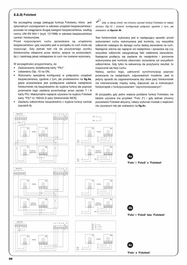
68
2.2.3) Fototest
Na szczególną uwagę zasługuje funkcja Fototestu, która jestoptymalnym rozwiązaniem w zakresie urządzeń bezpieczeństwa ipozwala na osiągnięcie drugiej kategorii bezpieczeństwa, wedługnormy UNI EN 954-1 (wyd. 12/1998) w zakresie bezpieczeństwacentral i fotokomórek.Przed rozpoczęciem ruchu sprawdzane są urządzeniabezpieczeństwa i gdy wszystko jest w porządku to ruch może sięrozpocząć. Gdy jednak test nie da pozytywnego wyniku(fotokomórka oślepiona przez słońce, spięcie na przewodach,itp.) i zaistnieją jakaś odstępstwa to ruch nie zostanie wykonany.
W szczególności przypominamy, że:• Zastosowaniu dodatkowej karty “PIU”.• Ustawieniu Dip. 10 na ON, • Wykonaniu specjalnej konfiguracji w połączeniu urządzeń
bezpieczeństwa, zgodnie z tym, jak przestawiono na fig.4a,gdzie przewidziane jest podłączenie zasilanie nadajnikówfotokomórek nie bezpośrednio do wyjścia funkcji ale poprzezprzerwanie tego zasilania przechodząc przez zaciski 7 i 8karty PIU. Maksymalne napięcie używane na wyjściu Fototestkarty “PIU” to 100mA (2 pary fotokomórek NICE)
• Zasilaniu odbiorników bezpośrednio z wyjścia funkcji centrali(zaciski5-6).
Gdy, w danej chwili, nie chcemy używać funkcji Fototestu to należy
obniżyć Dip.10 i zmienić konfiguracjé połączeń zgodnie z tym, jak
wskazano na figurze 4b .
Test fotokomórek wykonany jest w następujący sposób: przedwykonaniem ruchu wykonywana jest kontrola, czy wszystkieodbiorniki należące do danego ruchu dadzą zezwolenie na ruch.Następnie odcina się napięcie od nadajników i sprawdza się czywszystkie odbiorniki zasygnalizują fakt odebrania zezwolenia.Następnie podłączy się zasilanie do nadajników i ponowniewykonywana jest kontrola obecności zezwolenia od wszystkichodbiorników. Gdy tylko ta sekwencja da pozytywny rezultat, torozpocznie się faza ruchu.Należy, oprócz tego, uaktywnić synchronizację poprzezprzerwanie na nadajnikach, odpowiednich mostków. Jest tojedyny sposób do zagwarantowania aby dwie pary fotokomóreknie interweniowały między sobą. Zapoznać sié w instrukcjachfotokomęrek z funkcjonowaniem “zsynchronizowanym”.
W przypadku gdy jedno wejście poddane funkcji Fototestu niebédzie używane (na przykład “Foto 2“) i gdy jednak chcemypozostawić Fototest aktywny, należy wykonać mostek z wejściemnie używanym tak jak wskazano na fig.4c.
139 10765 8(Karty PIU)
9 8101112 7
78911 1012
(Karty PIU) 139 10765 8
1098 13765
7
10
PIU
PIU8
11
PIU
PIU
PIU 8
RX
43 51 2
6
FOTO
5107
RX
543
FOTO 2
21
65
(Karty PIU)
7
RX
54321
6
FOTO
RX
107
(Karty PIU)FOTO 2
5
10PIU6
7
531 2 4
5
RX
3 4 51 2
6
107
5
FOTO
10PIU
PIU 11
RX
1 2
712
PIUPIU
21
3 4 51 2
RX
53 41 2
8 7
TX
1012 11 9
(Karty PIU)
1 2
TX
21
FOTO 2
FOTO
(Karty PIU)
7PIU
21
RX
42 3 5
65
56
21
RX
2 3 4 5
TX
FOTO
21
TX
(Karty PIU)FOTO 2
1 2
1
1
1 2
712
PIUPIU
RX
3 4 51 2
TX
1 2
FOTO
12PIU
TX
TX
TX
TX
TX
“Foto“ i “Foto2“ z “Fototest“
“Foto“ i “Foto2“ bez “Fototest“
“Foto“ z “Fototest“
4a
4b
4c

PL
69
2.2.4) Kontrola połączeń
Następne czynności będą wykonywane na obwodach podnapięciem. Większość obwodów jest pod niskim napięciem więcnie są niebezpieczne, niektóre jednak części poddane sąnapięciu sieciowemu, dlatego też są BARDZO NIEBEZPIECZNE!Poniższe czynności wykonywać bardzo ostrożnie i NIGDYSAMODZIELNIE!
• Podłączyć zasilanie do centrali i sprawdzić czy pomiędzyzaciskami 5-6 napięcie wynosi 24 Vpp.
• Sprawdzić, czy po przerywanym i szybkim świeceniu, diodaOK zacznie świecić z regularnymi przerwami.
• Sprawdzić czy wszystkie diody wejść z kontaktami typu NC(Zwykle Zamknięte) świecą się (wszystkie zabezpieczeniauaktywnione) i czy odpowiednie diody wejść typu NA (ZwykleOtwarte) się nie świecą (bez jakiejkolwiek rozkazu), gdy tak niejest należy sprawdzić połączenia i funkcjonowanieposzczególnych urządzeń. Wejście ALT interweniujewyłączając FCA jak i FCC
• Sprawdzić połączenie wyłączników krańcowych; poruszyćdżwignią wyłącznika krańcowego i sprawdzić czy odpowiedniwyłącznik krańcowy zainterweniuje poprzez wyłączenieodpowiedniej diody na centrali.
• Odblokować skrzydło, ustawić na połowie biegu izablokować. W ten sposób skrzydło będzie wolne do ruchuotwierania i zamykania.
• Teraz należy sprawdzić czy ruch zostanie wykonany wewłaściwym kierunku. Należy sprawdzić zgodność pomiędzyruchem przewidzianym w centrali z tym wykonywanym przez
skrzydło. Kontrola ta jest podstawową kontrolą. Gdy kierunekjest błędny, w niektórych przypadkach ( na przykład wsystemie półautomatycznym) to automatyzm mógłby pozorniefunkcjonować poprawnie. Cykl OTWIERA jest podobny docyklu ZAMYKA, z podstawową różnicą, że urządzeniabezpieczeństwa są ignorowane w ruchu zamyka, któryzwykle jest najniebezpieczniejszy, i zainterweniują powodujączamykanie na przeszkodzie z efektami katastroficznymi!
• Aby sprawdzić czy kierunek obrotu jest właściwy wystarczydać krótki impuls na wejście Skok po Skoku; pierwszy ruch,który zaraz po włączeniu wykonuje centrala to Otwiera,dlatego też wystarczy sprawdzić czy automatyzm rusza się wkierunku otwierania. Gdy ruch odbywa się w kierunkuprzeciwnym wówczas należy:
� Wyłączyć zasilanie,� Obrócić o 180˚ łącze zasilania silnika i wyłącznika
krańcowego. (Odp. “O” odp. “V” na Fig.1),� Po wykonaniu powyższych czynności ponownie
sprawdzić czy kierunek obrotu jest właściwy.
Dioda “OK” umieszczona pośrodku karty ma za zadanie
sygnalizować stan logiki wewnętrznej: regularne przerywane świecenie z
przerwą 1sekundy, wskazuje, że mikroprocesor wewnętrzny jest
uaktywniony i oczekuje na polecenia. Gdy jednak ten sam mikroprocesor
rozpoznaje zmianę stanu wejścia (wejście impulsu jak i dip-switch funkcji),
to świeci w sposób szybki przerywany, nawet wtedy gdy zmiana ta nie
powoduje efektów natychmiastowych. świecenie szybkie trwające 3
sekundy wskazuje, że centrala została odłączona od zasilania i wykonuje
test części wewnętrznych. świecenie przerywane w sposób nierówny,
wskazuje, że test nie został zakończony pozytywnie i że istnieje wada.
!
Regulacje można wykonać poprzez trymery, którymi zmienia sięnastępujące parametry:
Czas Pracy (TL): Reguluje maksymalny czas trwania ruchu otwierania i zamykania.
Aby uregulować czas pracy TL, należy wybrać system pracy“Półautomatyczny” ustawiając Nr 1 Dip-Switch na ON po czymuregulować TL na połowie biegu. Tymi regulacjami wykonać cyklotwierania i zamykania, ewentualnie wykonać regulację trymeraTL w taki sposób, aby czas był wystarczający na wykonaniacałego ruchu i jeszcze pozostało około 2, 3 sekund czasu.Gdy nawet po ustawieniu trymera TL w pozycji maksymalnej, nieotrzyma się dostatecznego czas, należy przerwać mostek TLM,pomiędzy trymerem TL i TP, tak aby przedłużyć czas Pracy.
Czas Przerwy (TP):W funkcjonowaniu “automatycznym” reguluje się czas pomiędzyzakończeniem ruchu otwierania i rozpoczęciem ruchu zamykania.
Aby uregulować Czas Przerwy TP, wybrać sposóbfunkcjonowania “Automatyczny” przestawiając Dip-Switch Nr 2na ON, następnie wyregulować czas przerwy trymerem TPwedług życzenia. Aby wykonać kontrolę należy wykonać ruchotwierania, po czym zmierzyć czas przed rozpoczęciem ruchuzamykania.
Siła (F): Trymer F, obecny na centrali sterowniczej służy do regulacjiwartości maksymalnej Siły:
Regulację trymera SIŁY (F) wykonywać ostrożnie, ponieważ taregulacja może wpłynąć na stopień bezpieczeństwaautomatyzacji. Regulację należy wykonywać stopniowo mierzączastosowaną siłę skrzydła i dostosowując ją do wymagańnormatywnych.
W centrali RO1010 i OT21 SIŁA jest regulowana selektoremwielopozycyjnym, na pojemniku transformatora zasilania centrali.
3) Regulacje
TPTLF
TLM

70
Po zakończeniu kontroli i regulacji można przejść do prób ostatecznych urządzenia.
Próby ostateczne automatyzacji, muszą być wykonane przez doświadczony i wykwalifikowany personel, ze wzglédu, żepróby wykonywane będą w obecności niebezpieczeństwa.
Próby są fazą najważniejszą w realizacji automatyzacji. Każdy pojedynczy element, na przykład silnik, zatrzymanie w alarmie,fotokomórki, itp. Mogą wymagać specyficznej fazy kontroli i w tym też należy kierować się procedurami odpowiednich instrukcjiobsługi.
Próby ostateczne centrali należy wykonać według poniższej kolejności:
1. Selekcja funkcji: • Ustawić Dip Switch N˚1 na ON (Funkcjonowanie półautomatyczne)• Gdy zostały wykonane połączenia przedstawione na fig.4a do użytkowania funkcji Fototestu (gdy występuje karta PIU)
ustawić Dip Switch N˚10 na ON (Funkcja Fototest).• Ustawić wszystkie Dip Switch na OFF.
2. Przycisnąć przycisk Otwiera i sprawdzić czy:• Zaświeci się lampa sygnalizacyjna• Zacznie się ruch otwierania • Ruch zatrzyma się po osiągnięciu pozycji wyłącznika krańcowego otwierania FCA.
3. Przycisn przycisk Zamyka i sprawdzić czy: • Zaświeci się lampa sygnalizacyjna• Zacznie się ruch zamykania• Ruch zatrzyma się po osiągnięciu pozycji wyłącznika krańcowego zamykania FCC.
4. Rozpocząć ruch otwierania i sprawdzić czy podczas ruchu interwencja urządzenia: • Podłączone do wejścia Alt, powoduje zatrzymanie z krótką zmainy kierunku ruchu• Podłączone do wejścia Foto nie powoduje żadnego efektu • Podłączone do wejścia Foto2, powoduje zatrzymanie i inwersję ruchu (gdy występuje karta PIU).
5. Rozpocząć ruch zamykania i sprawdzić czy podczas ruchu zainterweniuje urządzenie:• Podłączone do wejścia Alt, powoduje zatrzymanie z krótką zmainy kierunku ruchu• Podłączone do wejścia Foto nie powoduje żadnego efektu • Podłączone do wejścia Foto2, powoduje zatrzymanie i inwersję ruchu (gdy występuje karta PIU)
6. Na połączonych wejściach sprawdzić czy uaktywnienie wejścia powoduje skok w sekwencji:• Wejście Skok po skoku: Sekwencja = Otwiera - Stop - Zamyka - Stop• Wejście Otwiera: Sekwencja = Otwiera - Stop - Otwiera - Stop• Wejście Zamyka: Sekwencja = Zamyka - Stop - Zamyka - Stop• Wejście Otwiera Częściowo: Sekwencja = Otwiera Częściowo - Stop - Zamyka - Stop (gdy jest karta PIU).
7 Gdy używa się funkcji fototestu sprawdzić funkcjonowanie testu (gdy jest karta PIU):• Przerwać fotokomórkę Foto, rozpocząć więc nowy ruch i sprawdzić czy zostanie wykonany test• Przerwać fotokomórkę Foto2, rozpocząć więc nowy ruch i sprawdzić czy zostanie wykonany test• Stworzyć spięcie w kontakcie fotokomórki Foto, rozpocząć więc nowy ruch i sprawdzić czy zostanie wykonany test • Stworzyć spięcie w kontakcie fotokomórki Foto2, rozpocząć więc nowy ruch i sprawdzić czy zostanie wykonany test
8. Wykonać próby odczytu Siły Uderzenia według tego jak zostało przewidziane w EN 12445.
Gdy po zakończeniu prób odbiorczych zostaną uaktywnione funkcje, które mogą ograniczyć bezpieczeństwo urządzenia, należywykonać specyficzne próby dla takich funkcji.
!
4) Próby ostateczne
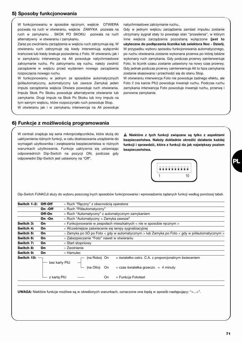
PL
71
5) Sposoby funkcjonowania
W funkcjonowaniu w sposobie ręcznym, wejście OTWIERApozwala na ruch w otwieraniu, wejście ZAMYKA pozwala naruch w zamykaniu . SKOK PO SKOKU pozwala na ruchalternatywny w otwieraniu i zamykaniu. Zaraz po zwolnieniu zarządzenia w wejściu ruch zatrzymuje się. Wotwieraniu ruch zatrzymuje się kiedy interweniują wyłącznikikrańcowe lub kiedy brakuje pozwolenia z Foto. W otwieraniu jak iw zamykaniu interwencja na Alt powoduje natychmiastowezatrzymanie ruchu. Po zatrzymaniu się ruchu, należy zwolnićzarządzenie w wejściu przed wydaniem nowego zarządzeniarozpoczęcia nowego ruchu.W funkcjonowaniu w jednym ze sposobów automatycznych(półautomatyczny, automatyczny lub zawsze Zamyka) jedenimpuls zarządzenia wejścia Otwiera powoduje ruch otwierania.Impuls Skok Po Skoku powoduje alternatywnie otwieranie lubzamykanie. Drugi impuls na Skok Po Skoku lub inny impuls natym samym wejściu, które rozpoczynało ruch powoduje Stop.W otwieraniu jak i w zamykaniu interwencja na Alt powoduje
natychmiastowe zatrzymanie ruchu..Gdy w jednym wejściu zarządzenia zamiast impulsu zostanieutrzymany sygnał stały to powstaje stan “przesilenia”, w któryminne wejścia zarządzenia pozostaną wyłączone (jest toużyteczne do podłączenia licznika lub selektora Noc - Dzień).W przypadku wyboru sposobu funkcjonowania automatycznego,po ruchu otwierania zostanie wykonana przerwa po której bédziewykonany ruch zamykania. Gdy podczas przerwy zainterweniujeFoto, to licznik czasu zostanie ustawiony na nowy czas przerwy.Gdy jednak podczas przerwy zainterweniuje Alt to faza zamykaniazostanie skasowana i przechodzi się do stanu Stop.W otwieraniu interwencja Foto nie powoduje żadnego efektu, aleFoto 2 (na karcie PIU) powoduje inwersjé ruchu. Podczas ruchuzamykania interwencja Foto powoduje inwersjé ruchu, przerwę iponowne zamykanie.
W centrali znajduje się seria mikroprzełączników, które służą douaktywnienia różnych funkcji, w celu dostosowania urządzenie dowymagań użytkownika i zwiększenia bezpieczeństwa w różnychwarunkach użytkowania. Funkcje uaktywnia się ustawiającodpowiednich Dip-Switch na pozycji ON, podczas gdyodpowiedni Dip-Switch jest ustawiony na “Off”.
Niektóre z tych funkcji związane są tylko z aspektamibezpieczeństwa. Należy dokładnie określić działanie każdejfunkcji i sprawdzić, która z funkcji da jak największy poziombezpieczeństwa.
!
Dip-Switch FUNKCJI służy do wyboru poszczeg lnych sposobów funkcjonowania i wprowadzenia żądanych funkcji według poniższej tabeli.
Switch 1-2: Off-Off = Ruch “Ręczny” z obecnością operatoraOn -Off = Ruch “Półautomatyczny”Off-On = Ruch “Automatyczny” z automatycznym zamykaniemOn -On = Ruch “Automatyczny + Zamyka zawsze”
Switch 3: On = Funkcjonowanie w zespołach mieszkalnych < nie w sposobie ręcznym >Switch 4: On = Wcześniejsze zaświecenie się lampy sygnalizacyjnejSwitch 5: On = Zamyka po 5Ó po Foto < gdy w automatycznym > lub Zamyka po Foto < gdy w półautomatycznym >Switch 6: On = Zabezpieczenie “Foto” nawet w otwieraniuSwitch 7: On = Start stopniowySwitch 8: On = ZwolnienieSwitch 9: On = HamulecSwitch 10: (na Robo) On = światełko ostrz. C.A. z proporcjonalnym świeceniem
bez karty PIU (na Otto) On = czas światełka grzeczn. = 4 minuty
z kartą PIU On = Funkcja Fototest
UWAGA: Niektóre funkcje możliwe są w określonych warunkach, oznaczone one będą w sposób następujący: “<...>”.
6) Funkcje z możliwością programowania
101

72
6.1) Opis funkcjiPrzedstawiamy krótki opis funkcji, które można dodać ustawiając Dip-Switch na ON:
Switch 1-2: Off-Off = Ruch “Ręczny” (obecny operator)On-Off = Ruch “Półautomatyczny”Off-On = Ruch “Automatyczny” (zamykanie automatyczne)On-On = Ruch “Automatyczny+ Zamyka Zawsze”
W funkcjonowaniu “Ręcznym” ruch wykonywany jest tylko przy obecności zarządzenia (przycisk przyciśnięty). W “Półautomatycznym”wystarczy jeden impuls zarządzający i zostanie wykonany cały ruch, aż do zakończenia Czasu Pracy lub po osiągnięciu wyłącznikówkrańcowych. W funkcjonowaniu “Automatycznym” po otwieraniu wykonana zostanie przerwa i automatyczna faza zamykania. Funkcja“Zamyka Zawsze” interweniuje przy braku zasilania; gdy brama będzie otwarta to automatycznie rozpocznie się faza ruchu zamykaniapoprzedzony 5 - sekundowym przerywanym świeceniem lampy.
Switch 3: On = Funkcjonowanie w Zespołach Mieszkalnych (niedostępne w systemie ręcznym)Przy funkcjonowaniu w Zespołach Mieszkalnych po włączeniu ruchu otwierania, ruch nie może być przerwany innymi impulsamizarządzającymi na SKOK PO SKOKU lub OTWIERA, aż do momentu zakończenia ruchu.W ruchu zamykania nowy impuls zarządzający powoduje zatrzymanie i inwersję ruchu.
Switch 4: On = Wcześniejsze zaświecenie się lampy sygnalizacyjnej. Po impulsie zarządzającym najpierw uaktywnia się lampę i następnie po 5 s. (2 s. gdy jest to w systemie ręcznym) rozpoczyna się ruch.
Switch 5: On = Zamyka po 5" po Foto < gdy w automatycznym > lub Zamyka po Foto < gdy w półautomatycznym >Funkcja ta, gdy urządzenie jest działaniu w Automatycznym, służy do utrzymania bramy otwartej tylko na czas przejścia. Pozakończeniu interwencji FOTO ruch zatrzymuje się. Po 5 s. startuje ruch zamykania. W działaniu półautomatycznym interwencja FOTOw ruchu zamykania uaktywnia automatyczne zamykanie po uregulowanym czasie przerwy.
Switch 6: On = Zabezpieczenie (Foto) nawet w otwieraniuZwykle, zabezpieczenie "Foto" jest uaktywnione tylko w ruchu zamykania. Gdy Switch 6 zostanie ustawiony na "On" przerwaurządzenia zabezpieczającego powoduje przerwę ruchu nawet w otwieraniu. Gdy jest to w systemie Półautomatycznym lub Automatycznym to uzyska się rozpoczęcie ruchu w otwieraniu zaraz po zwolnieniuzabezpieczenia.
Switch 7: On = Start stopniowyWykonać rozpoczęcie ruchu w sposób stopniowy unikając niepożądanych trzęsień automatyzacji.
Switch 8: On = Zwolnienie Zwolnienie polega na zmniejszeniu prędkości do 30% prędkości nominalnej tak aby uniknąć wstrząsów na końcu ruchu.
Funkcja zwolnienia, opr cz zmniejszenia prędkości automatyzacji zmniejsza o 70% moment silnika.
W automatyzacjach, gdzie wymagany jest moment wysoki, redukcja ta może spowodować natychmiastowe zatrzymanie silnika.
Wersja ROBO - THOR:Po zakończeniu ruchu otwierania lub zamykania spowodowanegozakłóceniem Czasu Pracy wykonana jest faza zwolnienia, któratrwa tyle co czas pracy.Gdy ruch kończy się po dziaóaniu wyłącznika krańcowego to fazazwolnienie nie będzie wykonana, naleśy więc wyregulować CzasPracy dopóki zacznie się zwolnienie 30-50 cm przed działaniemwyłącznika krańcowego.
Wersja OTTO:Po zakończeniu ruchu zamykania faza zwolnienia, gdy jestspowodowaną interwencją wyłączników krańcowych, trwa 3sekundy, gdy jest spowodowana zakończeniem Czasu Pracy trwatyle co Czas Pracy (mając na uwadze dobre funkcjonowanie zwol-nienia zalecane jest zastosowanie wyłączników krańcowych).W ruchu otwierania nie zostanie wykonane zwolnienie stopnioweale zatrzymanie stopniowe.
W przypadku zastosowania funkcji zwolnienia nainstalacjach czułych i gdy trwa ona więcej niż 3 sekundynależy założyć na zaciskach zasilania z sieci i w pobliżu
! centrali filtr sieciowy na około 6A z przytłumieniem do 30 dBaby nie przekroczyć granicy emisji elektromagnetycznejwskazanej w normie EN 50081-1.
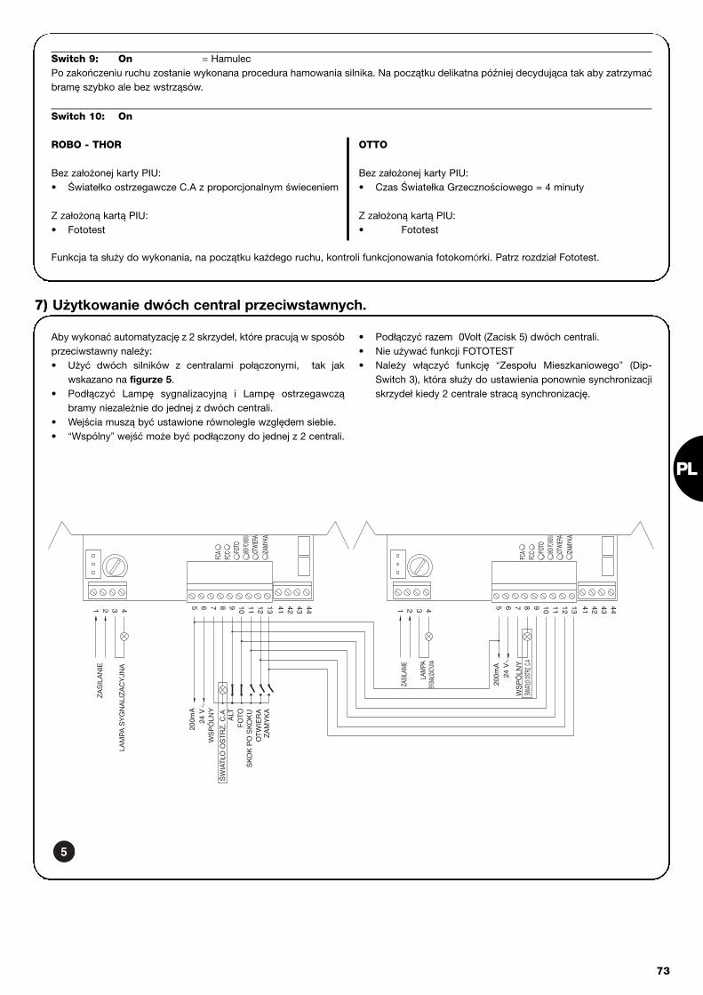
PL
73
Switch 9: On = HamulecPo zakończeniu ruchu zostanie wykonana procedura hamowania silnika. Na początku delikatna później decydująca tak aby zatrzymaćbramę szybko ale bez wstrząsów.
Funkcja ta służy do wykonania, na początku każdego ruchu, kontroli funkcjonowania fotokomórki. Patrz rozdział Fototest.
Aby wykonać automatyzację z 2 skrzydeł, które pracują w sposóbprzeciwstawny należy: • Użyć dwóch silników z centralami połączonymi, tak jak
wskazano na figurze 5.• Podłączyć Lampę sygnalizacyjną i Lampę ostrzegawczą
bramy niezależnie do jednej z dwóch centrali.• Wejścia muszą być ustawione równolegle względem siebie. • “Wspólny” wejść może być podłączony do jednej z 2 centrali.
• Podłączyć razem 0Volt (Zacisk 5) dwóch centrali.• Nie używać funkcji FOTOTEST• Należy włączyć funkcję “Zespołu Mieszkaniowego” (Dip-
Switch 3), która służy do ustawienia ponownie synchronizacjiskrzydeł kiedy 2 centrale stracą synchronizację.
7) Użytkowanie dwóch central przeciwstawnych.
444342411210 11 1386 75 9431 2
24 V
200m
A
ZAMY
KAOT
WIER
ASKO
K PO SKO
KU
4442 431311 12 41
FCC FO
TO
ZAMY
KAOT
WIER
ASKO
K PO SKO
KUFO
TO
FCA
FCC
FCA
97 85 6 1042 31
ZA
MY
KA
SK
OK
PO
SK
OK
UO
TW
IER
A
ALT
WS
PÓ
LNY
ŚW
IATŁ
O O
STR
Z. C
.A
200m
A24
V
FO
TO
LAM
PA S
YG
NA
LIZA
CY
JNA
WS
PÓ
LNY
ŚWIAT
ŁO OS
TRZ. C
.A
LAM
PASYG
NALIZ
ACYJN
A
ZAS
ILA
NIE
ZASI
LANI
E
Switch 10: On
ROBO - THOR
Bez założonej karty PIU:• Światełko ostrzegawcze C.A z proporcjonalnym świeceniem
Z założoną kartą PIU:• Fototest
OTTO
Bez założonej karty PIU:• Czas Światełka Grzecznościowego = 4 minuty
Z założoną kartą PIU:• Fototest
5
74
Karta PIUCentrala zawiera już wszystkie funkcje, które będą używane w normalnym instalowaniu. Aby zaspokoić wymagania stawiane pod-czas wykorzystywania specjalnych urządzeń została stworzona Karta PIU, która służy do osiągnięcia nowych funkcji, takich jak: syg-nalizacji semaforowych, światełka grzecznościowego, elektrozamknięcia, Foto 2, częściowego Otwierania i Fototestu.
Czerwony = Światło czerwone semaforaJest zwykle wyłączone, włączy się podczasruchu bramy.
Zielone = Światło zielone semaforaZwykle jest włączone, wyłączy się podczasruchu bramy.
Eletrozamknięcie = Wyjście zarządzenia elektrozamknięcia.Elektrozamknięcie jest uaktywnione po 1,5sekundach po rozpoczęciu ruchu otwierania.
Światełko grzecznościowe / Fototest = Wyjście, które jest używane do zarządzenia
światełkiem grzecznościowym, włączySwiatełko Grzecznościowe przy każdymrozpoczęciu ruchu, które będzie się świeciłochwilę dłużej po zakończeniu ruchu i nawet naczas zaprogramowany trymerem T.Cor.obecnym na karcie PIU. Gdy uaktywnia się funkcję fototestu (DIP 10 =ON) to wyjście służy do wykonania testufotokomórek na początku ruchu.
Otwiera Częściowo = Wejście do otwierania Częściowego (Otwiera
Częściowo, Stop, Zamyka, Stop). Wykonuje tęsamą funkcję jak Skok po skoku na karciegłównej, z tą różnicą, że ruch Otwiera trwaprzez czas ustawiony trymerem T.AP.P. nakarcie PIU.
Foto 2 = Wejście 2° urządzenia bezpieczeństwa. Tourządzenie bezpieczeństwa interweniuje tylkow jednym ruchu otwierania powodujączatrzymanie, z ewentualnym ponownymzamknięciem gdy centrala jestzaprogramowana w sposobie funkcjonowaniaPółautomatycznego lub Automatycznego.
24 V = Wyjście 24 V stosowane do zasilania funkcjitakich jak fotokomórki lub inne. Zacisk 11 jesttakże wspólnym dla wszystkich wejść.
Karta RADIOW centrali przygotowane jest łącze na włożenie karty radiowej, wyprodukowanej przez Nice. Karta ta służy do interwencji na wejściuSKOK PO SKOKU i zarządzania centralą na odległość poprzez nadajnik.
8) Akcesoria dodatkowe
Centrala, jako część elektroniczna, nie wymaga czynnościspecjalnych konserwacyjnych. Należy sprawdzić co jakiś czas (conajmniej co 6 miesięcy) działanie i stan regulacji urządzenia doregulacji Siły silnika, ewentualnie wyregulować trymerem.Wykonać całą fazę prób ostatecznych aby sprawdzić działanie
wyłączników krańcowych, urządzeń bezpieczeństwa(fotokomórki, brzegi pneumatyczne, itp.) jak i działanie lampysygnalizacyjnej.
9) Czynności konserwacyjne
Produkt ten składa się z wielu surowców, niektóre z nich mogąbyć powtórnie przerobione. Należy zasięgnąć informacji odnoście sposobów przerobu i zbytuproduktów według aktualnie obowiązujących norm miejscowych.
Niektóre elementy mogą zawierać substancje trujące, niewolno ich porzucać w środowisku!
10) Zbyt

PL
75
Jest to instrukcja, która ma pomóc instalatorowi w rozwiązaniuniektórych najczęściej spotykanych problemów wynikających wfazie instalowania:
Nie świeci się żadna z Diod• Sprawdzić czy centrala jest zasilana (sprawdzić czy napięcie
na zaciskach 1-2 i czy na zaciskach 5-6 napięcie jest równeokoło 24Vpp.)
• Sprawdzić czy 2 bezpieczniki topikowe zasilania są dobre. Gdyteraz żadna z diod nie zaświeciła się to możliwe, że istniejepoważna wada i należy wymienić centralę.
Diod OK świeci się regularnie ale Diody Wejść nie wskazująstanu wejść. • Sprawdzić uważnie połączenia na zaciskach wejść 7÷13
Ruch rozpoczyna się • Sprawdzić czy diody zabezpieczeń: Alt (FCA + FCC), FOTO, i
ewentualnie Foto2 świecą się i czy Dioda zarządzająca, którazostanie uaktywniona (Skok Po Skoku, Otwiera lub Zamyka)zaświeci się na czas trwania zarządzenia.
Podczas ruchu brama wykonuje inwersjęPowodem inwersji może być: • Interwencja fotokomórek (Foto2 podczas otwierania lub Foto
podczas zamykania); w tym przypadku sprawdzić połączeniafotokomórek i ewentualnie sprawdzić Diody sygnalizacji wejłą.
11) Co robić gdy....
Zasilanie sieci : 230 Vpp 50/60 HzWersja/ V1 : 120 Vpp 50/60 Hz
Prąd Max funkcji 24 V : 200mAWyjście lampy sygnalizacyjnej : Do lamp z napięciem sieciowym, moc max 40 WWyjście lampy ostrzegawczej bramy otwartej “SCA” : Do lamp ostrz. 24Vpp, moc max 2 W Temperatura pracy : -20÷70 ĄCCzas Pracy na ROBO/THOR : Z możliwością regulacji od 2.5 do >60 s lub od <50 do >120 s z TLMCzas Pracy na OTTO : Z możliwością regulacji od 2.5 do >20s lub od <20 do >40 s z TLMCzas Przerwy : Z możliwością regulacji od 5 do >160 s.
Na Karcie PIUCzas otw. Częściowego ROBO/THOR : Z możliwością regulacji od 1 do > 30 s.Czas otw. Częściowego OTTO : Z możliwością regulacji od 1 do > 14 s.Czas światła grzecznościowego : Z możliwością regulacji od 1 do > 180 s.
12) Dane techniczne

76
besturingseenheid reductiemotorsrobo, thor, otto
Aanbevelingen:
Deze handleiding is alleen bestemd voor gekwalificeerdtechnisch personeel dat met de installatie belast is. Geenenkele informatie uit deze handleiding kan als van belangvoor de eindgebruiker beschouwd te worden!Deze handleiding heeft alleen betrekking op deze besturings-eenheid en mag niet voor andere producten gebruikt worden.Het verdient aanbeveling alle aanwijzingen tenminste éénmaal nauwkeu-rig door te lezen alvorens met de installering te beginnen.
!
Inhoudsopgave: pag.
1 Beschrijving van het product 17
2 Installatie 182.1 Voorbeeld van een installatie 182.2 Elektrische aansluitingen 182.2.1 Elektrisch schema 192.2.2 Beschrijving van de aansluitingen 192.2.3 Fototest 202.2.4 Controle van de aansluitingen 21
3 Afstellingen 21
4 Eindtest 22
5 Manier van functioneren 23
pag.
6 Programmeerbare functies 236.1 Beschrijving van de functies 24
7 Toepassing van 2 besturingseenheden op in tegenovergestelde richting werkende vleugels 25
8 Apart leverbare accessoires 26
9 Onderhoud 26
10 Afvalverwerking 26
11 Wat te doen als… 27
12 Technische gegevens 27

NL
77
1) Beschrijving van het product:Met deze besturingseenheid voor het automatiseren van automati-sche poorten en deuren kunnen de éénfasewisselstroomreductie-motoren ROBO, THOR, OTTO aangestuurd worden.Al naar gelang het type aan te sturen reductiemotor verschillen debesturingseenheden van elkaar, zoals bijvoorbeeld: "AfstellingKracht", "Controlelampje Poort Open " en “Gebruikerslicht”.Er zijn bovendien een reeks functies die met behulp van dipschake-laars (microschakelaars) geselecteerd kunnen worden en afstellin-gen die met trimmers uitgevoerd kunnen worden.
De status van de ingangen wordt door speciale ledlampjes bij deingangen aangegeven; een ander ledlampje bij de microprocessorgeeft aan dat de interne logica correct functioneert.
Om de verschillende delen gemakkelijker te kunnen herkennen zijnop afb.1 de belangrijkste onderdelen aangegeven.
Code Product* Code Besturingseenheid* Extra functie
ROBORO1000RO1020
ROA3 Trimmer “Afstelling Kracht”
RO1010 ROA4 Relais “Start”
THOR TH1551 THA5 Trimmer “Afstelling Kracht”TH2251 THA6 Relais “Start”
OTTO OT21 OTA1 Uitgang “Gebruikerslicht”
* = voeg V1 aan de code toe voor uitvoering op 120 V 50/60 Hz
LMNOP
J
QRST
V U
I
X
W
YHG
FZ
EDCBA
CH
P.P.
AP
FOTO
FCA
FCCOK
Dipschakelaar voor het selecteren van de functiesTrimmer voor het afstellen van ” Kracht " Trimmer voor het afstellen van Werkingsduur (TL)Trimmer voor het afstellen van Pauzeduur (TP)Klemmenbord voor Antenne en 2de kanaalInsteekgleuf RADIO-kaartLedlampjes voor het aangeven van status ingangenKlemmenbord Ingangen / Uitgangen voor instructieRelais “Gemeenschappelijk”Klemmenbord stroomvoorziening / KnipperlichtPrimaire connector transformatorZekering lijn (5A)Connector uitgang “Gebruikerslicht” (alleen op OTTO)Uitgang stroomvoorziening motorConnectorinsteekgleuf condensatorRelais “Start”Triac “Gebruikerslicht” (alleen op OTTO)Triac “Sluit”Triac “Open”Secundaire connector transformatorIngang eindschakelaar FCA / FCCZekering laagspanning (500mA)Insteekgleuf kaart PIULedlampjes OKMicroprocessor
ABCDEFGHIJLMNOPQRSTUVWXYZ
1

2.1) Voorbeeld van een installatie
Om enkele termen en aspecten van een automatiseringsinstallatie voor deuren of poorten te verduidelijken geven wij u hier een typisch voorbeeld.
ROBO en THOR OTTO
1) Stel fotocellen “Foto”2) Knipperlicht3) Sleutelschakelaar4) Pneumatische lijst5) Stel fotocellen “Foto 2”
Met name herinneren wij u aan het volgende:• Alle door Nice geproduceerde fotocellen beschikken over een synchronisatiesysteem waarmee het mogelijk is het probleem van interfe-
rentie tussen twee stellen fotocellen op te lossen (zie voor verdere bijzonderheden de aanwijzingen voor de fotocellen).• Het stel fotocellen "Foto" heeft bij het openen geen gevolgen terwijl het bij het sluiten ervoor zorgt dat de poort omkeert.• Het stel fotocellen "Foto2” heeft bij het sluiten geen gevolgen terwijl het bij het openen ervoor zorgt dat de poort terugloopt.
78
2.2) Elektrische aansluitingen
Om de veiligheid van de installateur te waarborgen enschade aan de componenten te voorkomen is het bij hetmaken van de aansluitingen of het inpluggen van de ver-schillende kaarten absoluut noodzakelijk de besturings-eenheid uit te schakelen.• Sluit de besturingseenheid met een kabel van 3 x 1,5 mm2 op het
net aan; als de afstand tussen de besturingseenheid en de aan-sluiting op de installatie meer dan 30 m bedraagt, dient u in debuurt van de besturingseenheid voor aarding te zorgen.
• Bij aansluitingen in het op zeer lage veiligheidsspanning werkendedeel dient u kabeltjes met een minimumdoorsnede van 0,25 mm2
te gebruiken.• Gebruik afgeschermde kabeltjes als de lengte meer dan 30 m
bedraagt en aard het omhulsel alleen aan de zijde van de bestu-ringseenheid.
• Maak geen aansluitingen op kabels in boxen onder de grond, ookal zijn die helemaal waterdicht.
• De ingangen van de contacten van het type Normaal gesloten(NC), indien niet gebruikt, dienen via een brug met "gemeen-schappelijk 24V " verbonden te worden met uitzondering van deingangen van de fotocellen, indien de functie “Fototest” geacti-veerd wordt. U gelieve voor verdere informatie de paragraaf "Foto-test" te lezen.
• Als er voor dezelfde ingang meerdere contacten Normaal geslo-ten (NC) zijn, dan worden die onderling serieel geschakeld.
• De ingangen van de contacten van het type Normaal open (NO),dienen, indien niet gebruikt, vrij gehouden te worden.
• Als er voor dezelfde ingang meerdere contacten Normaal open(NO) zijn, dan worden die onderling parallel geschakeld.
• De contacten moeten mechanische contacten zijn en geen enkelpotentiaal hebben; aansluitingen in fasen zoals die welke "PNP","NPN", "Open Collector" etc. gedefinieerd worden, zijn niet toege-staan.
!
Wij brengen u hierbij in herinnering dat installaties metautomatische poorten en deuren uitsluitend door gekwa-lificeerd technisch personeel en met inachtneming van de
wettelijke voorschriften geïnstalleerd mogen worden. Volgnauwgezet de aanbevelingen van het boekje: "Aanbeve-lingen voor de installateur".
!
2) Installatie:
2a 2b
FOTO
FOTO
FOTO 2
5
3
2
1
3
4
FOTO
21

NL
79
2.2.1) Elektrisch schema
SLUITOPEN
SLUITOPEN
STOP
Stroomvoorzieningvia elektriciteitsnet
2.2.2) Beschrijving van de aansluitingen
Hier volgte een beknopte beschrijving van mogelijke aansluitingen van de besturingseenheid naar buiten.
Klemmetjes Functie Beschrijving
1-2 : Stroomvoorziening = Toevoerlijn van het elektriciteitsnet
3-4 : Knipperlicht = Uitgang voor aanslsuiting van het knipperlicht op de netspanning (Max. 40W)
5-6 : 24 Vac = Stroomvoorziening neveninrichtingen 24Vac (Foto, Radio, etc.) Max 200mA
7 : Gemeenschappelijk = Gemeenschappelijk voor alle ingangen
8 : Controlelampje P.O. (SCA) = “Controlelampje Poort Open” 24Vac max. 2W (Niet aanwezig op de uitvoering OTTO)
9 : Stop = Ingang met functie voor het onderbreken van de manoeuvre waarbij de richting eventjes
wordt omgekeerd
10 : Foto = Ingang voor veiligheidsinrichtingen (fotocellen, pneumatische lijsten)
11 : Stap-voor-stap (PP) = Ingang voor cyclische manoeuvre (“Open” - “Stop” - “Sluit” - “Stop”)
12 : Open = Ingang voor openingsmanoeuvre
13 : Sluit = Ingang voor sluitmanoeuvre
41-42 : 2° Ch Radio = Uitgang van een eventueel tweede kanaal van de radio-ontvanger
43-44 : Antenne = Ingang voor de antenne van de radio-ontvanger
3

80
2.2.3) Fototest
De "Fototest" verhoogt de betrouwbaarheid van de veiligheidsinrich-tingen waardoor het mogelijk is "categorie 2" van de norm EN 954-1 (uitgave 12/1998) te bereiken voor wat betreft de combinatiebesturingseenheid en veiligheidsfotocellen. Telkens wanneer er eenmanoeuvre van start gaat, worden alle veiligheidsinrichtingen gecon-troleerd en alleen als de test een positief resultaat geeft, gaat demanoeuvre van start. Als de test daarentegen geen positief resultaatheeft (fotocel door de zon verblind, kortsluiting kabels etc.) wordt destoring gedetecteerd en de manoeuvre niet uitgevoerd.
Om de functie "Fototest" te verkrijgen zijn de volgende punten nood-zakelijk:• Gebruik de supplementaire kaart PIU• Zet de dipschakelaar 10 op ON • Sluit de veiligheidsinrichtingen aan zoals dat op afb. 4a te zien is
waarbij de stroomvoorziening van de zenders van de fotocellenniet rechtstreeks via de uitgang van de neveninrichtingen plaatsvindt, maar door deze stroomvoorziening via de klemmetjes 7 en8 op de kaart PIU te onderbreken. De maximaal beschikbare stroom op de uitgang "Fototest" op dekaart PIU is 100mA (2 stel fotocellen Nice).
• Voorzie de ontvangers rechtstreeks via de uitgang neveninrichtin-gen van de besturingseenheid (klemmetjes 5-6) van stroom.
Als u later de functie Fototest niet meer wilt gebruiken, behoeft u alleen
maar dipschakelaar 10 naar beneden te halen en de configuratie van de aan-
sluitingen te wijzigen zoals dat op afb.4b is aangegeven.
Het testen van de fotocellen vindt als volgt plaats: wanneer er eenbedieningsopdracht voor een manoeuvre gegeven wordt, wordt ereerst nagegaan of alle ontvangers die met deze manoeuvre van doenhebben, hun ok geven; daarna wordt de stroomvoorziening naar dezenders onderbroken en wordt vervolgens gecontroleerd of alle ont-vangers dit feit signaleren door hun ok in te trekken; tenslotte wordtde stroomvoorziening van de zenders weer ingeschakeld en wordt eropnieuw gecontroleerd of alle ontvangers hun ok geven. Alleen alsdeze serie controles een positief resultaat heeft, zal de manoeuvrevan start gaan. Het is raadzaam ook het synchronisme te activerendoor de bruggetjes op de zenders te doorbreken; dit is de enigemethode om ervoor te zorgen dat er tussen de twee stellen fotocel-len geen interferentie plaats vindt. Controleer in de handleiding vande fotocellen de aanwijzingen voor een gesynchroniseerde werking.
Indien een ingang die aan de "Fototest" onderworpen is, niet wordtgebruikt (Voorbeeld "Foto2") en u toch de functie fototest wilt, dientu een brug tussen de niet gebruikte ingang aan te brengen zoals datop afb.4c te zien is.
“Foto” en “Foto2” met “Fototest”
“Foto” en “Foto2” zonder “Fototest”
“Foto” met “Fototest”
4a
4b
4c
139 10765 8(Kaart PIU)
9 8101112 7
78911 1012
(Kaart PIU) 139 10765 8
1098 13765
7
10
PIU
PIU8
11
PIU
PIU
PIU 8
RX
43 51 2
6
FOTO
5107
RX
543
FOTO 2
21
65
(Kaart PIU)
7
RX
54321
6
FOTO
RX
107
(Kaart PIU)FOTO 2
5
10PIU6
7
531 2 4
5
RX
3 4 51 2
6
107
5
FOTO
10PIU
PIU 11
RX
1 2
712
PIUPIU
21
3 4 51 2
RX
53 41 2
8 7
TX
1012 11 9
(Kaart PIU)
1 2
TX
21
FOTO 2
FOTO
(Kaart PIU)
7PIU
21
RX
42 3 5
65
56
21
RX
2 3 4 5
TX
FOTO
21
TX
(Kaart PIU)FOTO 2
1 2
1
1
1 2
712
PIUPIU
RX
3 4 51 2
TX
1 2
FOTO
12PIU
TX
TX
TX
TX
TX

NL
81
2.2.4) Controle van de aansluitingen
Bij het uitvoeren van onderstaande handelingen werkt u metonder spanning staande circuits. Op het merendeel van de circuitsstaat laagspanning en daar bestaat dus geen gevaar, maar op som-mige delen staat de spanning van het elektriciteitsnet, die dusUITERST GEVAARLIJK zijn! Let heel goed op wat u doet enWERK NOOIT ALLEEN!
• Sluit de stroomtoevoer op de besturingseenheid aan en controleeronmiddellijk of er tussen de klemmetjes 5-6 een spanning vanongeveer 24 Vac. aanwezig is.
• Controleer dat het ledlampje "OK" na eventjes snel geknipperd tehebben, nu regelmatig knippert.
• Verifieer nu dat de ledlampjes van de ingangen van het type "NC"(alle veiligheidsinrichtingen actief) branden, terwijl de bij de ingan-gen van het type "NO" behorende ledlampjes (geen enkele bedie-ningsopdracht aanwezig) uit zijn. Als dit niet het geval is, dient u tecontroleren of de aansluitingen correct zijn uitgevoerd en de ver-schillende inrichtingen goed werken. De ingang "Stop" treedt inwerking door zowel de eindschakelaar FCA als de eindschakelaarFCC uit te zetten.
• Verifieer of de eindschakelaars goed aangesloten zijn; haal de hen-del van de eindschakelaar over en controleer of de desbetreffendeeindschakelaar in werking treedt, waarbij het bijbehorende led-lampje op de besturingseenheid uit gaat
• Ontgrendel de vleugel en breng die ongeveer halverwege, ver-grendel deze; op deze manier kan de vleugel zowel bij het openenals bij het sluiten vrij bewegen.
• Nu dient u te verifiëren of de manoeuvre in de juiste richting plaatsvindt, d.w.z. te controleren of de door de besturingseenheid door-gegeven manoeuvre overeenkomt met de daadwerkelijk door devleugels uitgevoerde manoeuvre. Deze controle is van fundamenteelbelang; als de richting in bepaalde gevallen niet juist is (bijvoorbeeldin de semi-automatische modus), zou het erop kunnen lijken dat
het automatisme regelmatig functioneert; de cyclus ”open” isimmers gelijk aan de cyclus “Sluit” met dat fundamentele verschilechter dat de veiligheidsinrichtingen genegeerd zullen worden bij desluitmanoeuvre - die normaal gesproken de gevaarlijkste is - en bijopening in werking zullen treden, waardoor ze een hersluiting tegenhet obstakel zullen veroorzaken met desastreuze gevolgen!
• Om te controleren of de draairichting correct is, behoeft u alleenmaar een korte impuls op de ingang PP te geven; de eerstemanoeuvre die de besturingseenheid uitvoert nadat u haar onderspanning gezet heeft is altijd "Open", dus kunt u ermee volstaan tecontroleren of de automatisering een openingsmanoeuvre start.Indien de manoeuvre in verkeerde richting wordt uitgevoerd ,dientu als volgt te werk te gaan:
� Schakel de stroomvoorziening uit� Draai de stekker voor stroomvoorziening van de motor met
180° evenals die van de eindschakelaars. (Ref. "O" en ref. "V" op afb.1 )
� Na afloop hiervan is het raadzaam opnieuw te kijken of de draairichting in orde is; u begint hiervoor bij het laatste punt.
Het ledlampje "OK" op het midden van de kaart heeft tot taak de sta-
tus van de interne logica aan te geven: wanneer het regelmatig knippert met
tussenpozen van 1 seconde wil dit zeggen dat de interne microprocessor
actief is en in afwachting is van een bedieningsopdracht. Wanneer de micro-
processor een wijziging in de status van een ingang constateert (zowel een
bedieningsingang als een dipschakelaar voor een functie), gaat het lampje
tweemaal snel knipperen, ook als die wijziging geen onmiddellijk gevolg heeft.
Snel knipperen gedurende 3 seconden wil zeggen dat de besturingseenheid
zojuist onder spanning is gezet en een test op de interne onderdelen uitvoert;
onregelmatig knipperen wil zeggen dat de uitslag van de test niet positief is en
dat er dus een storing is opgetreden.
!
Afstellingen vinden plaats via trimmers die voor wijziging van onder-staande parameters zorgen:
Werkingsduur (TL):Hiermee wordt de maximale tijdsduur van de openings- of sluit-manoeuvre afgesteld. Voor de afstelling van de TL, selecteert u dewerkingsmodus "Semi-automatisch" door de dipschakelaar 1 op ONte zetten en vervolgens de trimmer TL halverwege te zetten. Voer bijdeze afstellingen een openings- en sluitingscyclus uit en stel de trim-mer TL eventueel zodanig bij, dat er voldoende tijd is om de gehelemanoeuvre uit te voeren en er ook nog een zekere speling van 2 of3 seconden overblijft. Indien er niet genoeg tijd is om de gehelemanoeuvre uit te voeren, ook al hebt u de trimmer TL op het maxi-mum gezet, dient u de brug TLM die zich op de print tussen de trim-mers TL en TP bevindt, te verbreken om de Werkingsduur te verlen-gen teneinde een Langere Werkingsduur (TLM) te verkrijgen.
Pauzeduur (TP):Bij "automatische" werking wordt met deze functie de tijd tussen heteinde van de openingsmanoeuvre en het begin van de sluitmanoeu-vre afgesteld. Om de TP af te stellen selecteert u de werkingsmodus"Automatisch" door de dipschakelaar 2 op ON te zetten en vervol-gens de trimmer TP naar wens af te stellen. Om dit te controlerendient u een openingsmanoeuvre uit te voeren en daarna de tijd tecontroleren die er tot de "Automatische" hersluiting verstrijkt.
Kracht (F):Op de besturingseenheid kunt u de waarde van de maximale"Kracht" afstellen.Speciale aandacht dient u aan de afstelling van de trimmer "Kracht"(F) te schenken; deze afstelling kan van invloed zijn op de graad vanveiligheid van de automatisering. Voor het afstellen hiervan dient uproefondervindelijk te werk te gaan door meerdere malen achterelkaar de door de vleugel toegepaste kracht te meten en deze te ver-gelijken met wat de voorschriften gebieden.Bij de besturingseenheden voor RO1010 en OT21 wordt de "Kracht"afgesteld via een keuzeschakelaar met meerdere standen op debehuizing van de voedingstransformator van de besturingseenheid.
3) Afstellingen:
TPTLF
TLM
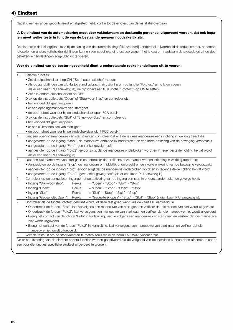
82
Nadat u een en ander gecontroleerd en afgesteld hebt, kunt u tot de eindtest van de installatie overgaan.
De eindtest van de automatisering moet door vakbekwaam en deskundig personeel uitgevoerd worden, dat ook bepa-len moet welke tests in functie van de bestaande gevaren noodzakelijk zijn.
De eindtest is de belangrijkste fase bij de aanleg van de automatisering. Elk afzonderlijk onderdeel, bijvoorbeeld de reductiemotor, noodstop,fotocellen en andere veiligheidsinrichtingen kunnen een specifieke eindtestfase vragen; het is daarom raadzaam de procedures uit de des-betreffende handleidingen zorgvuldig uit te voeren.
Voor de eindtest van de besturingseenheid dient u onderstaande reeks handelingen uit te voeren:
1. Selectie functies:• Zet de dipschakelaar 1 op ON (“Semi-automatische” modus)• Als de aansluitingen van afb.4a tot stand gebracht zijn, dient u om de functie "Fototest" uit te laten voeren
(als er een kaart PIU aanwezig is), de dipschakelaar 10 (Functie "Fototest") op ON te zetten.• Zet alle andere dipschakelaars op OFF
2. Druk op de instructietoets “Open” of “Stap-voor-Stap” en controleer of:• het knipperlicht gaat knipperen• er een openingsmanoeuvre van start gaat• de poort stopt wanneer hij de eindschakelaar open FCA bereikt.
3. Druk op de instructietoets “Sluit” of “Stap-voor-Stap” en controleer of:• het knipperlicht gaat knipperen• er een sluitmanoeuvre van start gaat• de poort stopt wanneer hij de eindschakelaar dicht FCC bereikt.
4. Laat een openingsmanoeuvre van start gaan en controleer dat er tijdens deze manoeuvre een inrichting in werking treedt die:• aangesloten op de ingang “Stop'”, de manoeuvre onmiddellijk onderbreekt en een korte omkering van de beweging veroorzaakt• aangesloten op de ingang “Foto”, geen enkel gevolg heeft• aangesloten op de ingang “Foto2”, ervoor zorgt dat de manoeuvre onderbroken wordt en in tegengestelde richting hervat wordt
(als er een kaart PIU aanwezig is) 5. Laat een sluitmanoeuvre van start gaan en controleer dat er tijdens deze manoeuvre een inrichting in werking treedt die:
• Aangesloten op de ingang “Stop”, de manoeuvre onmiddellijk onderbreekt en een korte omkering van de beweging veroorzaakt• aangesloten op de ingang “Foto”, ervoor zorgt dat de manoeuvre onderbroken wordt en in tegengestelde richting hervat wordt• aangesloten op de ingang “Foto2”, geen enkel gevolg heeft (als er een kaart PIU aanwezig is)
6. Controleer op de aangesloten ingangen of de activering van de ingang een stap in onderstaande reeks ten gevolge heeft:• Ingang “Stap-voor-stap”: Reeks = “Open” - “Stop” - “Sluit” - ”Stop”• Ingang “Open”: Reeks = “Open” - “Stop” - “Open” - “Stop”• Ingang “Sluit”: Reeks = “Sluit” - “Stop” - “Sluit” - “Stop”• Ingang “Gedeeltelijk Open”: Reeks = “Gedeeltelijk open” - “Stop” - “Sluit” - “Stop” (indien kaart PIU aanwezig is).
7 Controleer als de functie fototest gebruikt wordt, of deze test goed werkt (als de kaart PIU aanwezig is):• Onderbreek de fotocel “Foto”, laat vervolgens een manoeuvre van start gaan en verifieer dat die manoeuvre niet wordt uitgevoerd• Onderbreek de fotocel “Foto2”, laat vervolgens een manoeuvre van start gaan en verifieer dat die manoeuvre niet wordt uitgevoerd• Breng het contact van de fotocel “Foto” in kortsluiting, laat vervolgens een manoeuvre van start gaan en verifieer dat die manoeuvre
niet wordt uitgevoerd• Breng het contact van de fotocel “Foto2” in kortsluiting, laat vervolgens een manoeuvre van start gaan en verifieer dat die
manoeuvre niet wordt uitgevoerd.8. Voer de tests uit om de stootkrachten te meten zoals die in de norm EN 12445 voorzien zijn.Als er na uitvoering van de eindtest andere functies worden geactiveerd die de veiligheid van de installatie kunnen doen afnemen, dient ereen voor die functies specifieke eindtest uitgevoerd te worden.
!
4) Eindtest

NL
83
5) Manier van functioneren
Bij werking in de handbediende modus vindt er via de ingang “Open”een openingsmanoeuvre plaats en via de ingang ”Sluit” een sluit-manoeuvre. Via de ingang “Stap-voor-Stap” vindt er beurtelings eenopenings- en sluitmanoeuvre plaats.Zodra de binnenkomende instructie stopt, wordt de manoeuvreonderbroken. Bij opening wordt de manoeuvre onderbroken wan-neer de eindschakelaars in werking treden of als er geen toestem-ming van “Foto2” (op de kaart PIU) is; bij sluiting daarentegen wordtde manoeuvre onderbroken, als er geen toestemming is van “Foto”.Zowel bij opening als bij sluiting zorgt “Stop” er altijd voor dat demanoeuvre onmiddellijk wordt onderbroken. Wanneer de manoeuvreonderbroken is, dient de binnenkomende instructie gestopt te wor-den alvorens een nieuwe instructie een nieuwe manoeuvre kanbewerkstelligen. Bij werking in één van de automatische modi(“Semi-automatisch”, “Automatisch” of “Altijd sluiten”) veroorzaakteen bedieningsimpuls op de ingang “Open” een openingsmanoeu-vre. Een impuls op “Stap-voor-Stap” zorgt ervoor dat de poort beur-telings open of dicht gaat. Een tweede impuls op “Stap-voor-Stap”of op dezelfde ingang die de manoeuvre gestart heeft, veroorzaakt
een “Stop”. Zowel bij opening als bij sluiting zorgt “Stop” er altijd voordat de manoeuvre onmiddellijk wordt onderbroken en dat de poorteventjes terugloopt.Als er op een instructie-ingang in plaats van een impuls een doorlo-pend signaal wordt gegeven, ontstaat er een status van "voorkeur"waarbij de andere instructie-ingangen uitgeschakeld blijven (nuttigvoor het aansluiten van een tijdschakelaar of een keuze-schakelaar Dag-Nacht).Indien de automatische modus geselecteerd wordt, is er na een ope-ningsmanoeuvre een pauze, waarna een sluitmanoeuvre plaats vindt.Als “Foto” tijdens de pauze in werking treedt, wordt de timer met eennieuwe Pauzeduur teruggesteld; als “Stop” tijdens de pauze in wer-king treedt, wordt de functie van terugloop gewist en komt de instal-latie in “Stop”. Bij opening heeft het inwerkingtreden van ”Foto” geenenkele effect, terwijl “Foto2” (op de kaart PIU) ervoor zorgt dat debeweging tijdelijk onderbroken wordt; bij sluiting zorgt inwerkingtre-ding van “Foto” voor een omkering van de beweging, daarna eenpauze en vervolgens weer sluiting.
De besturingseenheid beschikt over een serie microschakelaarswaarmee u de verschillende functies kunt activeren om de installatiezoveel mogelijk aan de eisen van de gebruiker aan te passen en dezein de verschillende gebruikssituaties zo veilig mogelijk te maken.De functies worden geactiveerd door de desbetreffende dipschake-laar op de stand "On" te zetten, terwijl de functies waarvan de des-betreffende dipschakelaar op "Off'' staat, niet geactiveerd worden.
Sommige programmeerbare functies zijn verbonden aanveiligheidsaspecten, overweeg aandachtig de gevolgenvan een bepaalde functie en controleer welke functie degrootste mogelijke veiligheid biedt.
!
Met de dipschakelaars kunt u de verschillende manieren van functioneren selecteren en de gewenste functies volgens onderstaande tabel invoeren:
Schakelaar 1-2: Off-Off = "Handbediende" manoeuvre, d.w.z. er is iemand aanwezigOn -Off = "Semi-automatische" manoeuvreOff-On = "Automatische" manoeuvre, d.w.z. automatische sluitingOn -On = Manoeuvre "Automatisch + altijd sluiten"
Schakelaar 3: On = Werking Woningblok < niet beschikbaar in handbediende modus >Schakelaar 4: On = VoorwaarschuwingSchakelaar 5: On = Terugloop 5' na Foto < bij “Automatisch” > of Sluit na Foto < bij “Semi-automatisch” >Schakelaar 6: On = Beveiliging "Foto" ook bij openingSchakelaar 7: On = Geleidelijke startSchakelaar 8: On = VertragingSchakelaar 9: On = RemSchakelaar 10: (op Robo) On = Controlelampje Poort Open (SCA) met proportioneel knipperen
Zonder kaart PIU (op Otto) On = Duur gebruikerslicht = 4 minuten
Met kaart PIU On = Functie “Fototest”
N.B.: Sommige functies zijn onder bepaalde omstandigheden mogelijk, deze zijn aangegeven met de tussen de tekens "<...>" staandeopmerkingen.
6) Programmeerbare functies
101
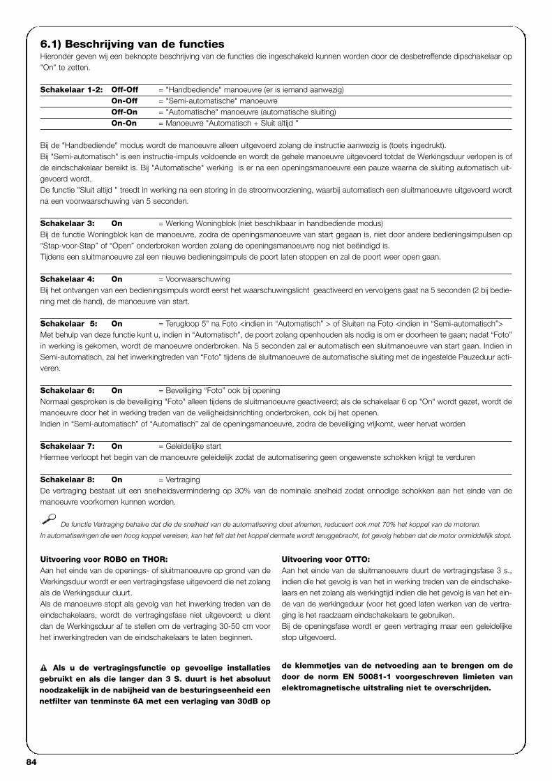
84
6.1) Beschrijving van de functiesHieronder geven wij een beknopte beschrijving van de functies die ingeschakeld kunnen worden door de desbetreffende dipschakelaar op"On" te zetten.
Schakelaar 1-2: Off-Off = "Handbediende" manoeuvre (er is iemand aanwezig)On-Off = "Semi-automatische" manoeuvreOff-On = "Automatische" manoeuvre (automatische sluiting)On-On = Manoeuvre "Automatisch + Sluit altijd "
Bij de "Handbediende" modus wordt de manoeuvre alleen uitgevoerd zolang de instructie aanwezig is (toets ingedrukt).Bij "Semi-automatisch" is een instructie-impuls voldoende en wordt de gehele manoeuvre uitgevoerd totdat de Werkingsduur verlopen is ofde eindschakelaar bereikt is. Bij "Automatische" werking is er na een openingsmanoeuvre een pauze waarna de sluiting automatisch uit-gevoerd wordt.De functie "Sluit altijd " treedt in werking na een storing in de stroomvoorziening, waarbij automatisch een sluitmanoeuvre uitgevoerd wordtna een voorwaarschuwing van 5 seconden.
Schakelaar 3: On = Werking Woningblok (niet beschikbaar in handbediende modus)Bij de functie Woningblok kan de manoeuvre, zodra de openingsmanoeuvre van start gegaan is, niet door andere bedieningsimpulsen op“Stap-voor-Stap” of “Open” onderbroken worden zolang de openingsmanoeuvre nog niet beëindigd is.Tijdens een sluitmanoeuvre zal een nieuwe bedieningsimpuls de poort laten stoppen en zal de poort weer open gaan.
Schakelaar 4: On = VoorwaarschuwingBij het ontvangen van een bedieningsimpuls wordt eerst het waarschuwingslicht geactiveerd en vervolgens gaat na 5 seconden (2 bij bedie-ning met de hand), de manoeuvre van start.
Schakelaar 5: On = Terugloop 5" na Foto <indien in “Automatisch” > of Sluiten na Foto <indien in “Semi-automatisch”>Met behulp van deze functie kunt u, indien in “Automatisch”, de poort zolang openhouden als nodig is om er doorheen te gaan; nadat “Foto”in werking is gekomen, wordt de manoeuvre onderbroken. Na 5 seconden zal er automatisch een sluitmanoeuvre van start gaan. Indien inSemi-automatisch, zal het inwerkingtreden van “Foto” tijdens de sluitmanoeuvre de automatische sluiting met de ingestelde Pauzeduur acti-veren.
Schakelaar 6: On = Beveiliging “Foto” ook bij openingNormaal gesproken is de beveiliging "Foto" alleen tijdens de sluitmanoeuvre geactiveerd; als de schakelaar 6 op "On" wordt gezet, wordt demanoeuvre door het in werking treden van de veiligheidsinrichting onderbroken, ook bij het openen.Indien in “Semi-automatisch” of “Automatisch” zal de openingsmanoeuvre, zodra de beveiliging vrijkomt, weer hervat worden
Schakelaar 7: On = Geleidelijke startHiermee verloopt het begin van de manoeuvre geleidelijk zodat de automatisering geen ongewenste schokken krijgt te verduren
Schakelaar 8: On = VertragingDe vertraging bestaat uit een snelheidsvermindering op 30% van de nominale snelheid zodat onnodige schokken aan het einde van demanoeuvre voorkomen kunnen worden.
De functie Vertraging behalve dat die de snelheid van de automatisering doet afnemen, reduceert ook met 70% het koppel van de motoren.
In automatiseringen die een hoog koppel vereisen, kan het feit dat het koppel dermate wordt teruggebracht, tot gevolg hebben dat de motor onmiddellijk stopt.
Uitvoering voor ROBO en THOR:Aan het einde van de openings- of sluitmanoeuvre op grond van deWerkingsduur wordt er een vertragingsfase uitgevoerd die net zolangals de Werkingsduur duurt.Als de manoeuvre stopt als gevolg van het inwerking treden van deeindschakelaars, wordt de vertragingsfase niet uitgevoerd; u dientdan de Werkingsduur af te stellen om de vertraging 30-50 cm voorhet inwerkingtreden van de eindschakelaars te laten beginnen.
Uitvoering voor OTTO:Aan het einde van de sluitmanoeuvre duurt de vertragingsfase 3 s.,indien die het gevolg is van het in werking treden van de eindschake-laars en net zolang als werkingtijd indien die het gevolg is van het ein-de van de werkingsduur (voor het goed laten werken van de vertra-ging is het raadzaam eindschakelaars te gebruiken.Bij de openingsfase wordt er geen vertraging maar een geleidelijkestop uitgevoerd.
Als u de vertragingsfunctie op gevoelige installatiesgebruikt en als die langer dan 3 S. duurt is het absoluutnoodzakelijk in de nabijheid van de besturingseenheid eennetfilter van tenminste 6A met een verlaging van 30dB op
de klemmetjes van de netvoeding aan te brengen om dedoor de norm EN 50081-1 voorgeschreven limieten vanelektromagnetische uitstraling niet te overschrijden.
!

NL
85
Schakelaar 9: On = RemAan het einde van de manoeuvre wordt er een remprocedure op de motor uitgevoerd, aanvankelijk lichtjes, maar dan steeds duidelijker omde poort snel maar zonder schokken te laten stoppen.
Met behulp van deze functie kunt u elke keer bij de aanvang van een manoeuvre controleren of de fotocellen goed werken. Zie het hoofd-stuk "Fototest"
Om een automatisering met 2 vleugels die in tegenovergestelde rich-ting werken aan te leggen dient u als volgt te werk te gaan:• Gebruik twee motoren waarvan de besturingseenheden aangeslo-
ten zijn zoals u dat op afb.5 kunt zien. • Sluit het waarschuwingslicht en het "Controlelampje Poort Open”
op één van de twee besturingseenheden, onverschillig welke, aan.• De ingangen moeten onderling parallel geschakeld worden.• Het "Gemeenschappelijk" van de ingangen kan op één van de 2
besturingseenheden worden aangesloten.
• Sluit de 0Volt (Klemmetje 5) van de twee besturingseenheden opelkaar aan.
• De functie "Fototest" mag niet gebruikt worden.• Het is raadzaam de functie "Woonblok" in werking te stellen (dip-
schakelaar 3) waarmee de 2 vleugels weer synchroon kunnen wer-ken, mochten de 2 besturingseenheden niet meer synchroon wer-ken
7) Toepassing van twee besturingseenheden op in tegenovergestelde richting werkende vleugels
Str
oo
mvo
orz
ieni
ngvi
a el
ektr
icite
itsne
t
Stro
omvo
orzi
enin
gvi
a el
ektri
cite
itsne
t
SLU
ITO
PE
NSL
UIT
OPEN
SLUI
TOP
EN
ST
OP
Schakelaar 10: On
ROBO en THOR
Zonder ingeplugde kaart PIU:• "Controlelampje Poort Open " met proportioneel knipperen
Met ingeplugde kaart PIU:• “Fototest”
OTTO
Zonder ingeplugde kaart PIU:• Duur “Gebruikerslicht” = 4 minuten
Met ingeplugde kaart PIU:• “Fototest”
5

86
Kaart PIUDe besturingseenheid omvat reeds alle functies die bij een normale installatie gebruikt worden. Om tegemoet te komen aan de eisen bijspeciale installaties is de speciale kaart PIU ontwerpen waarmee u nieuwe functies aan de installatie kunt toevoegen zoals verkeerslichten,gebruikerslampje, Elektroslot, "Foto2", gedeeltelijke opening en "Fototest".
Rood = Rood licht van het verkeerslichtGewoonlijk is dat altijd uit, maar het gaat bran-den wanneer de poort open of dicht gaat.
Groen = Groen licht van het verkeerslichtDit blijft gewoonlijk branden, maar het dooft wan-neer de poort open of dicht gaat.
Elektroslot = Uitgang voor instructie elektroslot.Het elektroslot wordt gedurende 1,5 s aan hetbegin van de openingsmanoeuvre geactiveerd
Gebruikerslicht/Fototest = Uitgang waarmee u als u dat gebruikt voor de
instructie gebruikerslampje, aan het begin vanelke manoeuvre een Gebruikerslampje kunt latenbranden dat tot na afloop van de manoeuvre blijftbranden en wel zolang als met de trimmer TijdGebruikerslampje op de kaart PIU geprogram-meerd is. Gebruikerslicht aanwezig op de kaart PIU.Als u de functie "Fototest" (dipschakelaar 10 =ON) activeert, maakt deze uitgang het mogelijkde fotocellen bij het begin van alle manoeuvres tetesten.
Open gedeeltelijk = Ingang voor gedeeltelijke opening("Gedeeltelijke opening" "Stop", "Sluit","Stop"). Deze functie doet hetzelfde als defunctie "Stap-voor-Stap" op de hoofdkaart,met dat verschil dat de manoeuvre "Open"zolang duurt als via de trimmer "Tijd Gedeel-telijke opening " op de kaart PIU is ingesteld.
Foto 2 = Ingang 2de veiligheidsinrichting. Dezeinrichting treedt alleen bij een openings-manoeuvre in werking en zorgt ervoor dat demanoeuvre onderbroken wordt, waarbij depoort eventueel gesloten wordt als de wer-kingsmodus "Semi-automatisch" of "Auto-matisch" op de besturingseenheid gepro-grammeerd is.
24 V = Uitgang 24V die gebruikt kan worden omde neveninrichtingen zoals fotocellen ofandere van stroom te voorzien. Het klemme-tje 11 is ook gemeenschappelijk voor deingangen .
RADIO-kaartDe besturingseenheid beschikt over een insteeksleuf voor het insteken van een Nice-radiokaart, waardoor het mogelijk is de ingang "Stap-voor-stap" te gebruiken en zo de besturingseenheid via een zender op afstand te bedienen.
8) Apart leverbare accessoires
Voor de besturingseenheid als elektronische component is geenenkel speciaal onderhoud vereist. Controleer echter periodiek (ten-minste eens in het half jaar), of de afstellingsinrichting van de Krachtvan de motor nog goed werkt; gebruik eventueel de trimmer om eenen ander bij te stellen.
Voer de eindtest in zijn geheel opnieuw uit om te controleren of deveiligheidsinrichtingen (fotocellen, pneumatische lijsten, etc.) en hetwaarschuwingslicht correct functioneren.
9) Onderhoud
Dit product bestaat uit verschillende soorten materialen, waarvansommige gerecycleerd kunnen worden. Win inlichtingen over de methoden van hergebruik of afvalverwerkingin en houd u aan de plaatselijk van kracht zijnde voorschriften.
Sommige elektronische onderdelen zouden vervuilendestoffen kunnen bevatten: laat ze niet in het milieu verdwij-nen.
!
10) Afvalverwerking
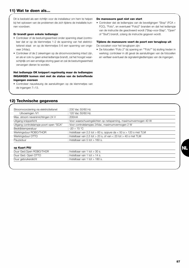
NL
87
Dit is bedoeld als een richtlijn voor de installateur om hem te helpenbij het oplossen van de problemen die zich tijdens de installatie kun-nen voordoen.
Er brandt geen enkele ledlampje• Controleer of de besturingseenheid onder spanning staat (contro-
leer dat er op de klemmetjes 1-2 de spanning van het elektrici-teitsnet staat en op de klemmetjes 5-6 een spanning van onge-veer 24Vac).
• Controleer of de 2 zekeringen op de stroomvoorziening intact zijn,en als er ook nu geen enkel ledlampje brandt, zal het hoogst waar-schijnlijk om een ernstige storing gaan en zal de besturingseenheidvervangen dienen te worden.
Het ledlampje OK knippert regelmatig maar de ledlampjesINGANGEN komen niet met de status van de betreffendeingangen overeen• Controleer nauwkeurig de aansluitingen op de klemmetjes van
de ingangen 7÷13.
De manoeuvre gaat niet van start• Controleer dat de ledlampjes van de beveiligingen "Stop" (FCA +
FCC), "Foto", en eventueel "Foto2" branden en dat het ledlampjevan de instructie die geactiveerd wordt ("Stap-voor-Stap", "Open"of "Sluit") brandt, zolang de instructie gegeven wordt.
Tijdens de manoeuvre voert de poort een terugloop uit De oorzaken voor het teruglopen zijn:• De fotocellen “Foto 2” bij opening en “”Foto”” bij sluiting treden in
werking; controleer in dit geval de aansluitingen van de fotocellenen verifieer eventueel de signaleringledlampjes van de ingangen.
11) Wat te doen als…
Stroomvoorziening via elektriciteitsnet : 230 Vac 50/60 HzUitvoeringen /V1 : 120 Vac 50/60 Hz
Max. stroom neveninrichtingen 24 V : 200mAUitgang knipperlicht : Voor waarschuwingslichten op netspanning, maximumvermogen 40 W Uitgang controlelampje poort open “SCA” : Voor controlelampjes 24Vac, maximumvermogen 2 WBedrijfstemperatuur : -20 ÷ 70 °CWerkingsduur ROBO/THOR : Instelbaar van 2,5 tot > 60 s, oppure da < 50 a > 120 s met TLMWerkingsduur OTTO : Instelbaar van 2,5 tot > 20 s, of van < 20 tot > 40 s met TLMPauzeduur : Instelbaar van 5 tot > 160 s.
op Kaart PIUDuur Ged.Open ROBO/THOR : Instelbaar van 1 tot > 30 s.Duur Ged. Open OTTO : Instelbaar van 1 tot > 14 s.Duur gebruikerslicht : Instelbaar van 1 tot > 180 s.
12) Technische gegevens

(secondo Direttiva 98/37/EC, Allegato II, parte B) (according to 98/37/EC Directive, Enclosure II, part B)
Numero /Number: 131/RO-TH-OT Data / Date: 9/2001 Revisione / Revision: 3
Il sottoscritto Lauro Buoro, Amministratore Delegato, dichiara che il prodotto: / The undersigned Lauro Buoro, General Manager, declares that the product:Nome produttore / Producer name: NICE s.p.a.Indirizzo / Address: Via Pezza Alta 13, 31046 Z.I. Rustignè - ODERZO- ITALYTipo / Type: Motoriduttore elettromeccanico 230 V.a.c. per cancelli scorrevoli / Electromechanical gear motor for sliding doorsModello / Model: RO1000, RO1010, RO1020, TH1551, TH2251, OT21 Accessori / Accessories: Scheda PIU, Ricevitore radio opzionale mod. K, BIO, FLO, FLOR / PIU Board, Optional Radio receiver mod. K, BIO, FLO, FLOR
Risulta conforme a quanto previsto dalle seguenti direttive comunitarie / Complies with the following community directivesRiferimento n° TitoloReference n° Title73/23/CEE, 93/68/CEE DIRETTIVA BASSA TENSIONE e successiva modifica/ Low Voltage Directive and subsequent modification89/336/CEE DIRETTIVA COMPATIBILITA’ ELETTROMAGNETICA (EMC) / EMC Electromagnetic Compatibility Directive98/37/CE (EX 89/392/CEE) DIRETTIVA MACCHINE / Machinery Directive
Risulta conforme a quanto previsto dalle seguenti Norme armonizzate / Complies with the following Harmonised standardsRiferimento n° Edizione Titolo Livello di valutazione ClasseReference n° Issue Title Assessment level ClassEN60335-1 04/1998 Sicurezza degli apparecchi elettrici d’uso domestico e similare – Norme generali.
Safety of household and electrical appliances – General requirementsEN60204-1 09/1993 Sicurezza del macchinario-Equipag. elettrico delle macchine-Parte 1:Reg.generali
Safety of machinery-Electrical equipment of machines-Part 1:General requirementsEN55022 09/1998 Apparecchi per la tecnologia dell’informazione. Caratteristiche di radiodisturbo. Limiti e metodi di misura B
Information technology equipment – Radio disturbance characteristics Limits and methods of measurement ENV50204 04/1996 Campo elettromagnetico irradiato dai radiotelefoni numerici - Prova di immunità. 10V/m A
Radiated electromagnetic fields from digital radio telephones - Immunity testEN61000-3-2-3 03/1995 Parti 2-3: Armoniche/Flicker A
Parts 2-3: Harmonic/FlickerCompatibilità elettromagnetica (EMC) / Electromagnetic compatibility (EMC)Parte 4: Tecniche di prova e di misura / Part 4: Testing and measurement techniques
EN61000-4-2 09/1996 Parte 2: Prove di immunità a scarica elettrostatica 6KV, 8KV BPart 2: Electrostatic discharge immunity test
EN61000-4-3 11/1997 Parte 3: Prova d’immunità sui campi irradiati a radiofrequenza 10V/m, APart 3: Radiated, radio-frequency, electromagnetic field immunity test
EN61000-4-4 09/1996 Parte 4: Test sui transienti veloci/ immunità ai burst 2KV, 1KV BPart 4: Electrical fast transient/burst immunity test.
EN61000-4-5 06/1997 Parte 5: Prova di immunità ad impulsi 4KV, 2KV BPart 5: Surge immunity test
EN61000-4-6 11/1997 Parte 6: Immunità ai disturbi condotti, indotti da campi a radiofrequenza 10V APart 6: Immunity to conducted disturbances, induced by radio-frequency fields.
EN61000-4-8 06/1997 Parte 8: Prova di immunità a campi magnetici a frequenza di rete 30A/m APart 8: Power frequency magnetic field immunity test.
EN61000-4-11 09/1996 Parte 11: Prove di immunità a buchi di tensione, brevi interruzioni e variazioni di tensione B-CPart 11: Voltage dips, short interruptions and voltage variations immunity tests
Risulta conforme a quanto previsto dalle altre norme e/o specifiche tecniche di prodotto / Complies with the other standards and/or product technicalspecifications Riferimento n° Edizione Titolo Livello di valutazione ClasseReference n° Issue Title Assessment level ClassEN 12445 11/2000 Industrial, commercial and garage doors and gates - Safety in use of power
operated doors - Test methodsEN 12453 11/2000 Industrial, commercial and garage doors and gates - Safety in use of power
operated doors - Requirements
Inoltre dichiara che non è consentita la messa in servizio del prodotto suindicato finché la macchina, in cui il prodotto stesso è incorporato,non sia identificata e dichiarata conforme alla direttiva 89/392/CEE / The above-mentioned product cannot be used until the machine into which it isincorporated has been identified and declared to comply with the 89/392/EEC directive.
Il prodotto suindicato si intende parte integrante di una delle configurazioni di installazione tipiche, come riportato nei nostri cataloghi generali/ The above product is an integral part of one of the typical installation configurations as shown in our general catalogues
Oderzo, li 11 Settembre 2001 (Amministratore Delegato)(General Manager)
Lauro Buoro
Dichiarazione CE di conformità / EC declaration of conformity
IST1
06.4
858
RE
V. 0
3 de
l 28-
02-2
005
Nice SpAOderzo TV ItaliaTel. +39.0422.85.38.38 Fax [email protected]
Nice PadovaSarmeola di Rubano PD ItaliaTel. +39.049.89.78.93.2 Fax [email protected]
Nice RomaRoma ItaliaTel. +39.06.72.67.17.61Fax [email protected]
Nice FranceBuchelayTel. +33.(0)1.30.33.95.95Fax +33.(0)1.30.33.95.96
Nice Rhône-AlpesDecines Charpieu FranceTel. +33.(0)4.78.26.56.53Fax +33.(0)4.78.26.57.53
Nice France SudAubagne FranceTel. +33.(0)4.42.62.42.52Fax +33.(0)4.42.62.42.50
Nice BelgiumLeuven (Heverlee)Tel. +32.(0)16.38.69.00Fax +32.(0)[email protected]
Nice España MadridTel. +34.9.16.16.33.00Fax [email protected]
Nice España BarcelonaTel. +34.9.35.88.34.32Fax [email protected]
Nice PolskaPruszkówTel. +48.22.728.33.22Fax [email protected]
Nice UKChesterfieldTel. +44.87.07.55.30.10Fax [email protected]
Nice ChinaShanghaiTel. +86.21.575.701.45/46Fax [email protected]
www.niceforyou.comNice Gate is the doors and gate automation division of Nice Nice Screen is the rolling shutters and awnings automation division of Nice