Thermo Scientific Thermolyne Furnace Small Benchtop Muffle ......(212°F) to 982°C (1800°F) for...
58
Thermo Scientific Thermolyne Furnace Small Benchtop Muffle/ Type FB1300 and FB1400 Installation and Operation Manual LT1256X1 Revision G October 2018
Transcript of Thermo Scientific Thermolyne Furnace Small Benchtop Muffle ......(212°F) to 982°C (1800°F) for...

Thermo Scientific Thermolyne FurnaceSmall Benchtop Muffle/Type FB1300 and FB1400 Installation and Operation Manual
LT1256X1 Revision G October 2018

© 2018 Thermo Fisher Scientific Inc. All rights reserved.
Thermo Fisher Scientific Inc. provides this document to its customers with a product purchase to use in the product operation. This document is copyright protected and any reproduction of the whole or any part of this document is strictly prohibited, except with the written authorization of Thermo Fisher Scientific Inc.
The contents of this document are subject to change without notice. All technical information in this document is for reference purposes only. System configurations and specifications in this document supersede all previous information received by the purchaser.
Thermo Fisher Scientific Inc. makes no representations that this document is complete, accurate or error-free and assumes no responsibility and will not be liable for any errors, omissions, damage or loss that might result from any use of this document, even if the information in the document is followed properly.
This document is not part of any sales contract between Thermo Fisher Scientific Inc. and a purchaser. This document shall in no way govern or modify any Terms and Conditions of Sale, which Terms and Conditions of Sale shall govern all conflicting information between the two documents.
Release history:
For Research Use Only. Not for use in diagnostic procedures.

C
Contents
Chapter 1 Safety Information . . . . . . . . . . . . . . . . . . . . . . . . . . . . . . . . . . . . . . . . . . . . . . 3Alert Signals. . . . . . . . . . . . . . . . . . . . . . . . . . . . . . . . . . . . . . . . . . . . . . . . . . . . . 4Important Information . . . . . . . . . . . . . . . . . . . . . . . . . . . . . . . . . . . . . . . . . . . . 4Warnings . . . . . . . . . . . . . . . . . . . . . . . . . . . . . . . . . . . . . . . . . . . . . . . . . . . . . . . 4Warning . . . . . . . . . . . . . . . . . . . . . . . . . . . . . . . . . . . . . . . . . . . . . . . . . . . . . . . 5
Chapter 2 Introduction . . . . . . . . . . . . . . . . . . . . . . . . . . . . . . . . . . . . . . . . . . . . . . . . . . 7Intended Use . . . . . . . . . . . . . . . . . . . . . . . . . . . . . . . . . . . . . . . . . . . . . . . . . . . . 8General Usage . . . . . . . . . . . . . . . . . . . . . . . . . . . . . . . . . . . . . . . . . . . . . . . . . . . 8Principles of Operation . . . . . . . . . . . . . . . . . . . . . . . . . . . . . . . . . . . . . . . . . . . . 8
Chapter 3 General Specification . . . . . . . . . . . . . . . . . . . . . . . . . . . . . . . . . . . . . . . . . . . 9FB1300 Models . . . . . . . . . . . . . . . . . . . . . . . . . . . . . . . . . . . . . . . . . . . . . . . . . . 9FB1400 Models . . . . . . . . . . . . . . . . . . . . . . . . . . . . . . . . . . . . . . . . . . . . . . . . . 10Environmental Conditions . . . . . . . . . . . . . . . . . . . . . . . . . . . . . . . . . . . . . . . . 10
Chapter 4 Unpacking . . . . . . . . . . . . . . . . . . . . . . . . . . . . . . . . . . . . . . . . . . . . . . . . . . . 11
Chapter 5 Installation . . . . . . . . . . . . . . . . . . . . . . . . . . . . . . . . . . . . . . . . . . . . . . . . . . . 13Site Selection . . . . . . . . . . . . . . . . . . . . . . . . . . . . . . . . . . . . . . . . . . . . . . . . . . . 14Electrical Connections . . . . . . . . . . . . . . . . . . . . . . . . . . . . . . . . . . . . . . . . . . . . 14FB1300 and FB1400 Models. . . . . . . . . . . . . . . . . . . . . . . . . . . . . . . . . . . . . . . 14
Chapter 6 Operation, All Models . . . . . . . . . . . . . . . . . . . . . . . . . . . . . . . . . . . . . . . . . . 15Power Switch. . . . . . . . . . . . . . . . . . . . . . . . . . . . . . . . . . . . . . . . . . . . . . . . . . . 16Cycle Light shown on the display . . . . . . . . . . . . . . . . . . . . . . . . . . . . . . . . . . . 16Door Safety Switch . . . . . . . . . . . . . . . . . . . . . . . . . . . . . . . . . . . . . . . . . . . . . . 16
Chapter 7 Single Setpoint Controller . . . . . . . . . . . . . . . . . . . . . . . . . . . . . . . . . . . . . . 17Eurotherm 3216 Controller Operation . . . . . . . . . . . . . . . . . . . . . . . . . . . . . . . 18Basic Operation . . . . . . . . . . . . . . . . . . . . . . . . . . . . . . . . . . . . . . . . . . . . . . . . . 18Buttons and Indicators. . . . . . . . . . . . . . . . . . . . . . . . . . . . . . . . . . . . . . . . . . . . 19To change the Setpoint . . . . . . . . . . . . . . . . . . . . . . . . . . . . . . . . . . . . . . . . . . . 19To View the Display Units . . . . . . . . . . . . . . . . . . . . . . . . . . . . . . . . . . . . . . . . 19Controller Parameters . . . . . . . . . . . . . . . . . . . . . . . . . . . . . . . . . . . . . . . . . . . . 19Alarms . . . . . . . . . . . . . . . . . . . . . . . . . . . . . . . . . . . . . . . . . . . . . . . . . . . . . . . . 20Sensor Break Protection. . . . . . . . . . . . . . . . . . . . . . . . . . . . . . . . . . . . . . . . . . . 20
Thermo Scientific Small Benchtop Muffle 1

Contents
Over – Temperature Protection (OTP) . . . . . . . . . . . . . . . . . . . . . . . . . . . . . . . 20Tuning . . . . . . . . . . . . . . . . . . . . . . . . . . . . . . . . . . . . . . . . . . . . . . . . . . . . . . . 21
Chapter 8 Single Ramp & Dwell . . . . . . . . . . . . . . . . . . . . . . . . . . . . . . . . . . . . . . . . . . 23Functions. . . . . . . . . . . . . . . . . . . . . . . . . . . . . . . . . . . . . . . . . . . . . . . . . . . . . . 24Program Overview. . . . . . . . . . . . . . . . . . . . . . . . . . . . . . . . . . . . . . . . . . . . . . . 25SetPoint Rate Limit Setup . . . . . . . . . . . . . . . . . . . . . . . . . . . . . . . . . . . . . . . . . 26Running the Program . . . . . . . . . . . . . . . . . . . . . . . . . . . . . . . . . . . . . . . . . . . . 26Holding the Program. . . . . . . . . . . . . . . . . . . . . . . . . . . . . . . . . . . . . . . . . . . . . 26Stopping the Program . . . . . . . . . . . . . . . . . . . . . . . . . . . . . . . . . . . . . . . . . . . . 26Clearing the Flashing End . . . . . . . . . . . . . . . . . . . . . . . . . . . . . . . . . . . . . . . . . 26Verifying a Running Program . . . . . . . . . . . . . . . . . . . . . . . . . . . . . . . . . . . . . . 26
Chapter 9 Furnace Loading . . . . . . . . . . . . . . . . . . . . . . . . . . . . . . . . . . . . . . . . . . . . . . 27
Chapter 10 Preventive Maintenance . . . . . . . . . . . . . . . . . . . . . . . . . . . . . . . . . . . . . . . . 29General Cleaning Instructions . . . . . . . . . . . . . . . . . . . . . . . . . . . . . . . . . . . . . . 29
Chapter 11 Maintenance and Servicing . . . . . . . . . . . . . . . . . . . . . . . . . . . . . . . . . . . . . 31To Replace Heating Element . . . . . . . . . . . . . . . . . . . . . . . . . . . . . . . . . . . . . . . 32To Replace Thermocouple. . . . . . . . . . . . . . . . . . . . . . . . . . . . . . . . . . . . . . . . . 34To Replace Insulation . . . . . . . . . . . . . . . . . . . . . . . . . . . . . . . . . . . . . . . . . . . . 35To Replace Door Switches. . . . . . . . . . . . . . . . . . . . . . . . . . . . . . . . . . . . . . . . . 36To Replace Solid State Relay . . . . . . . . . . . . . . . . . . . . . . . . . . . . . . . . . . . . . . . 36To Replace Controller . . . . . . . . . . . . . . . . . . . . . . . . . . . . . . . . . . . . . . . . . . . . 37
Chapter 12 Troubleshooting . . . . . . . . . . . . . . . . . . . . . . . . . . . . . . . . . . . . . . . . . . . . . . 39
Chapter 13 Replacement Parts List . . . . . . . . . . . . . . . . . . . . . . . . . . . . . . . . . . . . . . . . . 41
Chapter 14 Ordering Procedures . . . . . . . . . . . . . . . . . . . . . . . . . . . . . . . . . . . . . . . . . . . 43
Chapter 15 Wiring Diagrams . . . . . . . . . . . . . . . . . . . . . . . . . . . . . . . . . . . . . . . . . . . . . . 45FB1400 models . . . . . . . . . . . . . . . . . . . . . . . . . . . . . . . . . . . . . . . . . . . . . . . . . 46FB1300 models . . . . . . . . . . . . . . . . . . . . . . . . . . . . . . . . . . . . . . . . . . . . . . . . . 47
Chapter 16 Exploded View . . . . . . . . . . . . . . . . . . . . . . . . . . . . . . . . . . . . . . . . . . . . . . . 49
2 Small Benchtop Muffle Thermo Scientific
1
Safety Information
Contents
“Alert Signals” on page 4•
• “Important Information” on page 4
• “Warnings” on page 4
• “Warning” on page 5
Thermo Scientific Small Benchtop Muffle 3

1 Safety InformationAlert Signals
Alert Signals
Warnings alert you to a possibility of personal injury.
Cautions alert you to a possibility of damage to the equipment.
Notes alert you to pertinent facts and conditions.
Hot surfaces alert you to a possibility of personal injury if you come in contact with a surface during use or for a period of time after use.
Important InformationYour Thermo Scientific Thermolyne Type FB1300 Model or FB1400 Model Furnace has been designed with function, reliability and safety in mind. It is your responsibility to install it in conformance with local electrical codes. For safe operation, please pay attention to the alert signals throughout the manual.
This manual contains important operating and safety information.
You must carefully read and understand the contents of this manual prior to the use of this furnace. If the equipment is used in a manner not specified by the manufacturer, protection provided by the equipment may be impaired.
Warnings
To avoid electrical shock, this furnace must:
1. Use a properly grounded electrical outlet of correct voltage and current handling capacity.
2. Be disconnected from the power supply prior to maintenance and servicing.
3. Have the door switch operating properly.
To avoid burns, this furnace must:
Caution: Hot Surface - Avoid Contact. To avoid burns, do not touch the exterior or interior surfaces of this furnace during use or for a period of time after use.
To avoid personal injury:
1. Do not use in the presence of flammable or combustible materials; fire or explosion may result. This device contains components which may ignite such material.
4 Small Benchtop Muffle Thermo Scientific

1 Safety InformationWarning
2. Refer servicing to qualified personnel.
3. Always wear safety glasses or a safety shield and high temperature gloves when loading or unloading the furnace. Long sleeved, fire retardant clothing and a fire retardant apron is also recommended.
WarningThis warning is presented for compliance with California Proposition 65 and other regulatory agencies and only applies to the insulation in this product. This product contains refractory ceramic, refractory ceramic fiber or fiberglass insulation, which can produce respirable dust or fibers during disassembly. Dust or fibers can cause irritation and can aggravate pre-existing respiratory diseases. Refractory ceramic and refractory ceramic fibers (after reaching 1000°C) contain crystalline silica, which can cause lung damage (silicosis). The International Agency for Research on Cancer (IARC) has classified refractory ceramic fiber and fiberglass as possibly carcinogenic (Group 2B), and crystalline silica as carcinogenic to humans (Group 1).
The insulating materials can be located in the door, the hearth collar, in the chamber of the product or under the hot plate top. Tests performed by the manufacturer indicate that there is no risk of exposure to dust or respirable fibers resulting from operation of this product under normal conditions. However, there may be a risk of exposure to respirable dust or fibers when repairing or maintaining the insulating materials, or when otherwise disturbing them in a manner which causes release of dust or fibers. By using proper handling procedures and protective equipment you can work safely with these insulating materials and minimize any exposure. Refer to the appropriate Material Safety Data Sheets (MSDS) for information regarding proper handling and recommended protective equipment. For additional MSDS copies, or additional information concerning the handling of refractory ceramic products, please contact the Customer Service Department at 1-800-438-4851.
Thermo Scientific Small Benchtop Muffle 5

1 Safety InformationWarning
6 Small Benchtop Muffle Thermo Scientific

2
Introduction
Contents
“Intended Use” on page 8•
• “General Usage” on page 8
• “Principles of Operation” on page 8
Thermo Scientific Small Benchtop Muffle 7

2 IntroductionIntended Use
Intended UseThe Type FB1300 Model and FB1400 furnaces are general purpose laboratory and heat treating furnaces. For optimum element life, we recommend observing these temperature ranges: from 100°C (212°F) to 982°C (1800°F) for continuous use, or from 982°C (1800°F) to 1100°C (2012°F) for intermittent use. Continuous use is operating the furnace for more than 3 hours and intermittent use is operating the furnace for less than 3 hours.
The unit consists of a heating chamber and a digital controller.
General UsageDo not use this product for anything other than its intended usage.
Principles of OperationThe furnace chamber is heated by a single three section resistant heater which is embedded in a refractory material. The chamber is insulated with ceramic fiber insulation. The temperature is controlled by an electronic control. The temperature is measured by a thermocouple and is registered on a digital display. For safety, door switches are incorporated to remove power from the heating elements when the door is opened. The furnace is supported by the control section which also houses the electrical connections.
8 Small Benchtop Muffle Thermo Scientific

3
General Specification
FB1300 ModelsDimensions: (handle not included)
Chamber: 4” W x 3.75” H x 4.5” D (10.2 x 9.5 x 11.4 cm)
Overall : 7.9” W x 13.8” H x 8.5” D (20.0 x 34.9 x 21.6cm)
Chamber volume: 76 cu. in. (1.3 liters)
Weight: 15.7 lb. (7.1 kg)
Electrical Ratings:
Model # Volts Amps Watts Phase Frequency
FB1310 220-240 4.4 1060 1 50/60
FB1310M-26 220-240 4.4 1060 1 50/60
FB1310M-33 220-240 4.4 1060 1 50/60
FB1310M-33CN 220-240 4.4 1060 1 50/60
FB1310M-33CH 220-240 4.4 1060 1 50/60
FB1310M-33UK 220-240 4.4 1060 1 50/60
FB1314M 100 10.6 1060 1 50/60
FB1315M 120 8.9 1060 1 50/60
FB1318M 208 5.1 1060 1 50/60
Temperature: Operating Range (continuous): 982°C; (intermittent): 1100°C.
Thermo Scientific Small Benchtop Muffle 9

3 General SpecificationFB1400 Models
FB1400 ModelsDimensions: (handle not included)
Chamber: 5.00” W x 4.25” H x 6.00” D (12.7 x 10.8 x 15.2 cm)
Overall: 9.7” W x 15.8” H x 11.1” D (24.6 x 39.0 x 28.3cm)
Chamber volume: 129 cu. in. (2.1 liters)
Weight: 23 lb. (10.4 kg)
Electrical Ratings:
Model # Volts Amps Watts Phase Frequency
FB1410 220-240 6.3 1520 1 50/60
FB1410M-26 220-240 6.3 1520 1 50/60
FB1410M-33 220-240 6.3 1520 1 50/60
FB1410M-33CN 220-240 6.3 1520 1 50/60
FB1410M-33CH 220-240 6.3 1520 1 50/60
FB1410M-33UK 220-240 6.3 1520 1 50/60
FB1414M 100 14.5 1520 1 50/60
FB1415M 120 12 1520 1 50/60
FB1418M 208 7.3 1520 1 50/60
Temperature: Operating Range (continuous): 982°C; (intermittent): 1100°C.
Environmental ConditionsOperating: 17°C to 27°C; 20% to 80% relative humidity, non-condensing. Installation Category II
(overvoltage) in accordance with IEC 664. Pollution degree 2 in accordance with IEC 664.
Altitude Limit: 2,000 meters.
Storage: -25°C to 65°C; 20% to 80% relative humidity.
10 Small Benchtop Muffle Thermo Scientific

4
Unpacking
1. Visually check for any physical damage to the shipping container.
2. Inspect the equipment surfaces that are adjacent to any damaged area.
3. Open the furnace door and remove the packing material from inside the furnace chamber.
4. Vacuum the chamber prior to use to remove the insulation dust due to shipment.
5. Retain the original packaging material if reshipment is foreseen or required.
Thermo Scientific Small Benchtop Muffle 11

4 Unpacking
12 Small Benchtop Muffle Thermo Scientific

5
Installation
Contents
“Site Selection” on page 14•
• “Electrical Connections” on page 14
• “FB1300 and FB1400 Models” on page 14
Thermo Scientific Small Benchtop Muffle 13

5 InstallationSite Selection
Be sure ambient temperature does not exceed 40°C (104°F). The recommended ambient temperature is 17°C - 27°C. Ambient above this level may result in damage to the controller.
Allow at least six inches of space between the furnace, at least 40 inches above the furnace and any combustible surface. This permits the heat from the furnace case to escape so as not to create a possible fire hazard.
To avoid electrical shock, this furnace must always use a properly grounded outlet of correct voltage and current handling capacity.
Site SelectionInstall furnace on a sturdy surface and allow space for ventilation.
Electrical Connections1. The electrical ratings are located on the specification plate on the back of the furnace. Consult
customer service if your electrical service is different than those listed on the specification plate. Be sure the front power switch is in the OFF position before connecting the furnace to your electrical supply.
FB1300 and FB1400 Models
Electrical Conditions for operating the furnaces in the EU:
The furnaces are intended for use at a network supply with a maximum system impedance of Zmaxat the point of connection, according to EN 61000-3-11 clause 6.2.2. The user has to ensure that the device is operated on a network supply that meets these requirements. If necessary, the system impedance can be confirmed by the energy supplier.
The system impedance at the point of connection is typically less than 0.2 Ohm.
Unit Zmax [?]
FB1310M-33 0,28
FB1310M-33CN 0,28
FB1310M-33CH 0,28
FB1310M-33UK 0,28
FB1410M-33 0,34
FB1410M-33CN 0,34
FB1410M-33CH 0,34
FB1410M-33UK 0,34
14 Small Benchtop Muffle Thermo Scientific
6
Operation, All Models
Contents
“Power Switch” on page 16•
• “Cycle Light shown on the display” on page 16
• “Door Safety Switch” on page 16
Thermo Scientific Small Benchtop Muffle 15

6 Operation, All ModelsPower Switch
To avoid personal injury do not use in the presence of flammable or combustible chemicals; fire or explosion may result. This device contains components which may ignite such materials.
Caution: Avoid Contact. To avoid burns, this furnace must not be touched on the exterior or interior surfaces during use or for a period of time after use.
Always wear safety glasses or a safety shield and high temperature gloves when loading or unloading the furnace. Long sleeved, fire retardant clothing and a fire retardant apron is also recommended.
To avoid electrical shock, the door safety switch must be operating properly.
Power SwitchBoth the ON/OFF power switch and the digital display will illuminate when power is switched ON. The furnace will begin to heat to its controller's current setpoint. (See the instructions for your type of controller for information on checking and setting the setpoint.)
Cycle Light shown on the displayThe cycle light will illuminate whenever the power is being applied to the heating elements. The cycle light will turn on and off as the furnace reaches the setpoint.
Door Safety SwitchThe door safety switch removes power from the heating elements when the door is opened. Open and close the door a few times; Note an acoustic click of the switch during opening and closing of the door. If this condition is not true, consult the Troubleshooting section before proceeding. This check must be done when the furnace is heating and the cycle light on the display is illuminated.
16 Small Benchtop Muffle Thermo Scientific

7
Single Setpoint Controller
Contents
“Eurotherm 3216 Controller Operation” on page 18•
• “Basic Operation” on page 18
• “Buttons and Indicators” on page 19
• “To change the Setpoint” on page 19
• “To View the Display Units” on page 19
• “Controller Parameters” on page 19
• “Alarms” on page 20
• “Sensor Break Protection” on page 20
• “Over – Temperature Protection (OTP)” on page 20
• “Tuning” on page 21
Thermo Scientific Small Benchtop Muffle 17
7 Single Setpoint ControllerEurotherm 3216 Controller Operation
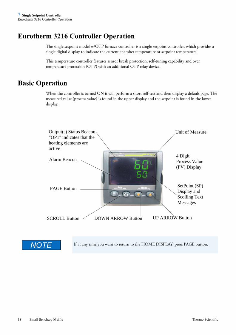
Eurotherm 3216 Controller OperationThe single setpoint model w/OTP furnace controller is a single setpoint controller, which provides a single digital display to indicate the current chamber temperature or setpoint temperature.
This temperature controller features sensor break protection, self-tuning capability and over temperature protection (OTP) with an additional OTP relay device.
Basic OperationWhen the controller is turned ON it will perform a short self-test and then display a default page. The measured value (process value) is found in the upper display and the setpoint is found in the lower display.
Alarm Beacon
Output(s) Status Beacon"OP1" indicates that theheating elements are active
PAGE Button
Unit of Measure
4 DigitProcess Value(PV) Display
SetPoint (SP)Display andScolling TextMessages
UP ARROW ButtonDOWN ARROW ButtonSCROLL Button
If at any time you want to return to the HOME DISPLAY, press PAGE button.
18 Small Benchtop Muffle Thermo Scientific

7 Single Setpoint ControllerButtons and Indicators
Buttons and IndicatorsOP1 (Output 1): Illuminates when the output is ON (normally heating). The cycle light on the display will turn on and off as the furnace reaches the setpoint.
OP2 (Output 2): Illuminates when the output is ON (normally cooling).
OP4 (Output 4): Illuminates when the AA relay output is ON (will go on during an alarm situation).
PAGE button: Allows you to select a new list of parameters.
SCROLL button: Allows you to select a parameter within a list of parameters.
DOWN button: Allows you to decrease a value.
UP button: Allows you to increase a value.
To change the SetpointIf you want to change the setpoint, press the SCROLL button until “SP1” is displayed. Press the UP or DOWN button until the desired setpoint value is displayed and then release the button. A few seconds after the button is released, the controller will accept the new value and is indicated by a brief flash of the display. Press PAGE button to return to HOME DISPLAY.
To View the Display UnitsPress SCROLL until “UNITS” is displayed. The temperature units are also shown on the HOME DISPLAY to the right of the measured value (process value).Temperature Units can be changed by pressing up and down buttons. Choice of Celsius (°C), Fahrenheit (°F), Kelvin (°K), Percentage (%), or None (nonE).
Controller Parameters
Home Display
°C ,°F, °K, %, or None: Temperature units in Celsius (default), Fahrenheit, Kelvin, Percentage (PErc), or None (nonE).A1.DHI: Deviation high alarm.A2.HI: High Limit alarm. Read Only. A3.LO: Low Limit alarm. Read Only. A.TUNE (tune): One-shot autotune enable.WRK.OP: Working Output power. Read Only. PV.OFS: Process Value Offset. Read Only.SP.RAT: Ramp Rate Setpoint (default units is minutes). RAMPU: Ramp Unit of measure (seconds, minutes and hours).DWELL: Time for dwell or delay (default units is minutes). T.STAT: Timer Status. Active only when timer is active.
Thermo Scientific Small Benchtop Muffle 19

7 Single Setpoint ControllerAlarms
TM.CFG: Timer configuration. TM.RES: Timer Resolution (minutes and hours). THRES: Timer start threshold (default is OFF). END.T: Timer End Type (default is DWELL).
Pid List
Pb: Proportional band (in display units).ti: Integral time in seconds.td: Derivative time in seconds.ACCESS List Code: Access code (Code needed to enter or change the other configuration parameters which are not normally accessible). Not accessible.
AlarmsThe controller will flash an alarm message in the home display if an alarm condition is detected.A2.HI: Measured value full scale high alarm.A1.DHI: Measured value deviation high alarm.S.br: Sensor break: check that sensor is connected correctly.LBR: Loop break: check that the heating circuits are working properly. Ld.F: Heater Circuit fault: indication of either an open or short solid state relay, a blown fuse, missing supply or open circuit heater.
Sensor Break ProtectionThis controller provides sensor break protection in the event the thermocouple opens. If an open thermocouple condition occurs, the digital display will blink “S.br” and the power to the heating element will be shut OFF (Cycle light on the display will extinguish).
Over – Temperature Protection (OTP)The OTP will be in effect during any alarm condition when the temperature of the furnace has deviated beyond the limit. The “Deviation High” alarm is the only alarm value, which can be changed. To change it, press the SCROLL button until “1dHi” appears on the display. Press the UP or DOWN button to select the OTP value you desire. We recommend a value of 20° above your working temperature to provide protection for your workload.
In addition to over-temperature protection, units containing a single setpoint controller w/OTP feature a mechanical OTP relay device, which disconnects power from the elements in an alarm condition.
20 Small Benchtop Muffle Thermo Scientific

7 Single Setpoint ControllerTuning
TuningThis controller incorporates a self-tuning feature, which determines the optimum control parameters for the best temperature accuracy with your load and setpoint. Use this feature the first time you use your furnace and each time you change either your setpoint or the type of load you are heating. Thermo Fisher Scientific recommends you use this feature to provide the best temperature accuracy the controller can attain. To use the tuning feature:
1. Start tuning with the process at ambient temperature. This allows the tuner to calculate the low cutback and high cutback values more accurately.
2. Adjust the setpoint to your desired value.
3. Press the SCROLL button until display reads, “A.TUNE.”
4. Press the UP or DOWN button to select, “on.”
5. Press the PAGE button to return to the HOME DISPLAY. The display will alternately flash between “tunE” and the HOME DISPLAY while tuning is in progress.
6. The controller will then turn the heating on and off to induce an oscillation. When the measured value reaches the required setpoint the first cycle will end.
7. Tuning will be complete after two oscillation cycles and then the tuner will turn itself off.
8. Normal control function will resume after the controller calculates tuning parameters.
Furnace must be at ambient temperature before starting a tune. “Stat” and “Sp.rr” must be set to OFF or “tunE” will not initiate.
Tune has completed when “tunE” stops flashing on display.
Thermo Scientific Small Benchtop Muffle 21

7 Single Setpoint ControllerTuning
22 Small Benchtop Muffle Thermo Scientific

8
Single Ramp & Dwell
Contents
“Functions” on page 24•
• “Program Overview” on page 25
• “SetPoint Rate Limit Setup” on page 26
• “Running the Program” on page 26
• “Holding the Program” on page 26
• “Stopping the Program” on page 26
• “Clearing the Flashing End” on page 26
• “Verifying a Running Program” on page 26
Thermo Scientific Small Benchtop Muffle 23

8 Single Ramp & DwellFunctions
FunctionsThis type of controller has two step ramp and dwell programming capabilities. The Ramp and Dwell can be configured to three different modes.
1. Mode 1 (DWELL) The dwell time begins once the setpoint reaches the set threshold. The END TYPE action is executed when the dwell timer reaches the end.
2. Mode 2 (DELY) The timer starts immediately upon instrument power-up or, when run is selected. The instrument remains in standby until the time has elapsed. After the time has elapsed, the instrument controls up to setpoint.
These instructions are used with the Single Setpoint models with OTP only (See models listed on front page).
24 Small Benchtop Muffle Thermo Scientific

8 Single Ramp & DwellProgram Overview
3. Mode 3 (SF.ST) Starts automatically on power up. This is a soft-start function. If the PV is below the Soft Start Threshold, then the power is limited to the Soft Start Limit until the threshold is met.
Program Overview• A program mode can be set by changing the “TM.CFG” variable (in the ‘Timer’ menu) to
“DWEL, DELY, or SF.ST.
The program must be stopped and the controller must be displaying the actual temperature before beginning the Setup.
• A Ramp rate may be set by changing the “SP.RAT” variable (in the ‘SP’ menu) to a value. The Ramp rate units are set with the “RAMPU” variable (in the ‘SP’ menu). The selections are Hour / Min / Sec.
• The Dwell time can be set by changing the “DWELL” variable (in the ‘Timer’ menu) to the desired value. Dwell time units are set with the “TM.RES” variable (in the ‘Timer’ menu). The selections are Hour / Min.
• The program Status can be set by changing the “T.STAT” variable to “run”, “hold”, or “res.” This variable will start, hold, or stop the program.”
• The Timer End Type can be set by changing the “END.T” to one of the four options:
? OFF - When the timer completes its dwell, the instrument will be put into Standby mode. The output power will be set to 0%, and the standard home display will display PV and OFF instead of setpoint.
? DWELL - When the timer completes, the controller will continue to control at setpoint.
? SP2 - When the timer completes the target setpoint will switch to setpoint 2. The setpoint 2 may be a lower or a higher temperature.
? Reset (rES) - The timer or program will reset on completion, reverting to the setpoint used at the point it was started.
The above four options is to set what is expected of the unit to do once the program is complete.For example, if it is desired for the controller to stop doing anything at all once the timer is finished, set End.T to OFF. If it is desired to revert back to the ambient temp setpoint at which the program started, set END.T to rES.
Thermo Scientific Small Benchtop Muffle 25

8 Single Ramp & DwellSetPoint Rate Limit Setup
SetPoint Rate Limit Setup1. Press the SCROLL button until the “SP.RAT” (Ramp Rate) is displayed.
2. Set the desired Ramp rate with the UP or DOWN buttons, if the ramp to setpoint feature is needed. If the Ramp rate is not needed, then set to “OFF” with the UP or DOWN buttons.
3. Press the SCROLL button until “TM.CFG” (Ramp & Dwell mode) will be displayed, select the desired mode with the UP or DOWN buttons. (DWEL, DELY, or SF.ST).
4. Press the SCROLL button until “DWELL” will be displayed set the desired Dwell time with the UP or DOWN buttons.
5. Press the PAGE button and SCROLL button together until the Actual temperature is displayed.
Running the Program1. Press the SCROLL button until “T.STAT” is displayed, set to “run” with the UP or DOWN
buttons; or from the HOME DISPLAY, press UP and DOWN arrows together.
2. Press the PAGE button to display Actual temperature.
Holding the Program1. Press the SCROLL button until “T.STAT” is displayed, set to “hold” with the UP or DOWN
buttons; or from the HOME DISPLAY, press UP and DOWN arrows together.
2. Press the PAGE button to display Actual temperature.
Stopping the ProgramPress the SCROLL button until “T.STAT” is displayed, set to “res” with the UP or DOWN buttons.
Clearing the Flashing EndPress the PAGE and SCROLL buttons at the same time.
It can also be cleared by pressing and holding the UP and DOWN arrows simultaneously until A-M (Auto/Manual) is displayed. Then select “Auto” and unit will clear program and revert to normal operation.
Verifying a Running ProgramPress the SCROLL button until “T.SAT” is displayed. The display will show “run” if the program is running, “hold” if it is paused or “res” if it is not running. Press the PAGE button to display Actual temperature.
26 Small Benchtop Muffle Thermo Scientific

9
Furnace Loading
Do not overload your furnace chamber. If the load is to be heated uniformly, it should not occupy more than two-thirds of the furnace chamber. Failure to observe this caution could result in damage to furnace components.
For best results, use only the center two-thirds of the furnace chamber.
• For best results of furnace loading, use less than two-thirds of any dimension of the chamber. Maintain a 3/4" clearance between the load and the sides of the chamber.
• If you are heating a number of small parts, spread them throughout the center of the furnace chamber.
• Keep objects away from thermocouple.
• Raise your load up off the furnace floor with small pieces of ceramic or a hearth plate to promote even heating.
• Use insulated tongs and mittens when loading and unloading furnace.
• Always wear safety glasses.
Thermo Scientific Small Benchtop Muffle 27

9 Furnace Loading
28 Small Benchtop Muffle Thermo Scientific

10
Preventive Maintenance
Before using any cleaning or decontamination method except those recommended by the manufacturer, users should check with customer service that the proposed method will not damage the equipment.
Disconnect the furnace from power supply before cleaning.
Opening the door for an extended period of time will cause the painted surfaces above the door to be discolored or burnt.
Contamination is a major cause of element failure, therefore, when possible, removes the fume forming material before heating (e.g., cleaning cutting oil from tool steel).
The resistance wire is high-grade nickel-chromium. Some chemicals notably sulphur, halogens, and cyanides, attack this wire at high temperatures, so avoid spilling these chemicals in the furnace or heating them any hotter than necessary. The refractory cement helps to protect the wire, but will not completely immunize it from damage. All heating elements must be considered expendable, and replacement is expected; however, reasonable care in their use will greatly extend the service they will give. As the manufacturer has no control over the use or care of the elements, no specific service guarantee can be made.
Housekeeping is vital to your electric furnace – KEEP IT CLEAN. Run your furnace up to 871°C (1600°F) empty occasionally to burn off the contamination that may exist on the insulation and elements. Run for approximately two hours with the door slightly open. See warning.
Element life is reduced somewhat by repeated heating and cooling. If the furnace is to be used again within a few hours, it is best to keep it at the operating temperature or at a reduced level such as 260°C (500°F).During normal use, the thermocouple in your furnace can become oxidized and cause inaccurate readings; therefore, We highly recommend that you replace the thermocouple periodically (once every six months) to ensure temperature accuracy.
General Cleaning InstructionsWipe exterior surfaces with lightly dampened cloth containing mild soap solution. The Troubleshooting section is intended to aid in defining and correcting possible service problems.
Thermo Scientific Small Benchtop Muffle 29

10 Preventive MaintenanceGeneral Cleaning Instructions
30 Small Benchtop Muffle Thermo Scientific

11
Maintenance and Servicing
Contents
“To Replace Heating Element” on page 32•
• “To Replace Thermocouple” on page 34
• “To Replace Insulation” on page 35
• “To Replace Door Switches” on page 36
• “To Replace Solid State Relay” on page 36
• “To Replace Controller” on page 37
Thermo Scientific Small Benchtop Muffle 31

11 Maintenance and Servicing
Disconnect the furnace from the power supply before servicing. Refer servicing to qualified personnel.
Perform only maintenance described in this manual. Contact an authorized dealer or our factory for parts and assistance.
It is seldom necessary to disconnect the thermocouple from the controller if the thermocouple is in good condition.
To Replace Heating Element1. Set the furnace on its top. (See Figure 3). Remove thermocouple cover. (If equipped.)
2. Remove screw and clamp holding thermocouple, then grasp the thermocouple at the bend where it enters the furnace chamber and pull straight back. Retain porcelain insulator.
3. When the thermocouple tip is clear of the furnace back, bend it out of the way.
4. Remove the screws holding the steel back plate to the case.
Remove the steel back plate.
Figure 1. Replacement of a Heating Element
5. Remove the back insulation block by opening the door and gently pushing it out. Support this insulation block while removing it, as it is quite soft and easily crumbled at the edges.
32 Small Benchtop Muffle Thermo Scientific

11 Maintenance and ServicingTo Replace Heating Element
6. Remove bottom cover to obtain access to terminals.
These steps will expose the heating element leads and insulating bushings in the bottom plate of the furnace.
7. Cut the element leads between the element and the terminal block. (There are two leads.) The element and hearth plate unit may now be removed by pushing it straight back out of the furnace. Use care not to damage the chamber insulation when removing the hearth plate and element as it can be reused if it has not been contaminated.
The hearth plate contains no heating coil, and may be saved for reinstallation if it is in good condition. The hearth plate is replaceable independent of the heating element.
8. Remove the old element lead wire and power wires from the terminal block, and save the sleeving for re-installation on the new element leads. Sleeving must be replaced if cracked or brittle!
9. New elements are shipped flat to protect them from damage in shipment, and to save space in storage. They must be formed before installation.
10. Place the element on a flat surface with the rough side up. Place a board or other straight edge along one row of notches.
11. Gently bend the element along the straight edge. The refractory cement will break along the row of notches. Make the bend 90°, avoiding excessive bending. (The element wires will be exposed at the corner thus formed. This will not affect its life or performance.)
12. Bend the other side of the element.
13. Place the hearth plate across the open end of the ‘’U” shaped element.
14. Slide the element and hearth plate unit into the chamber, pushing it firmly against the hearth collar. Use care not to damage the soft insulation. Remove any crumbs of insulation that may get between the unit and the hearth collar.
15. Thread the element leads through the ceramic bushings. Bend the leads so they lie close to the refractory plate and the bottom insulation block. (The easiest and safest way to do this is to press the wire flat with a stick or blunt pusher. Do not use a sharp object or nick the wire.)
16. Replace the sleeving and bend the lead 3/4 turns around the terminal screw. Cut off the excess wire. Replace power wires on top of element lead wires and tighten screw. Do not cross the wire over itself around the terminal; this makes it difficult to keep the connection tight and prevents good electrical contact. If you have excess wire, cut it off. Make sure element lead wires are not touching any other wires.
17. Replace the back insulation block and back plate.
18. Examine the thermocouple, and, if it is good, reinsert it into the chamber. It should extend about 1-1/2" into the chamber. Make sure porcelain insulator is in place for the thermocouple to pass through on the steel back plate. Replace clamp and screw. (Excessive scaling, pitting, or cracks are some indications that the thermocouple may need to be replaced.)
19. Replace bottom cover of control unit.
20. Replace thermocouple cover.
Thermo Scientific Small Benchtop Muffle 33

11 Maintenance and ServicingTo Replace Thermocouple
21. If replacement of back insulation is necessary, carefully redrill hole for thermocouple, using back cover as guide.
22. Reconnect furnace to power supply.
23. Test operation of furnace.
Nicking or damaging the element leads will cause premature element failure.
To Replace Thermocouple
Disconnect the furnace from the power supply before servicing.
If the thermocouple touches metal, this could short out the signal, causing the control to display room temperature. This could cause the furnace temperature to run away, possibly damaging furnace components.
1. Set furnace on its top.
2. Remove thermocouple cover. (If equipped.)
3. Remove screw and clamp holding the thermocouple, then grasp the thermocouple at the bend where it enters the chamber and pull it straight back from the furnace. Retain porcelain insulator.
4. Remove bottom cover.
5. Disconnect the thermocouple from the terminal block by removing the screws on the terminals. Pull the thermocouple through the hole in the furnace base and discard.
6. Insert the new thermocouple into the back of the furnace chamber. Make sure the porcelain insulator extends through the steel back plate to prevent the lead wires from touching metal.
7. Thread the thermocouple through the hole in the base which has a nylon insulator, replace clamp and screw.
8. Bend the thermocouple sharply toward terminal block.
9. Secure the two yellow wires marked “+”together on the terminal block. Secure the two red wires “-” together on the adjacent terminal. Make sure connections are secure to terminal block.
A polarity test of the thermocouple and lead wire is easily made with the use of a magnet. On chromel alumel thermocouples and lead wire, the nonmagnetic wire is positive (+) and the magnetic wire is negative (-).
10. Replace bottom plate.
11. Replace thermocouple cover. (If equipped.)
12. Reconnect furnace to power supply.
34 Small Benchtop Muffle Thermo Scientific

11 Maintenance and ServicingTo Replace Insulation
13. Test operation of furnace.
If the control temperature display moves downward, the thermocouple leads are reversed.
To Replace Insulation
Disconnect furnace from power supply before servicing.
1. Remove thermocouple cover. (If equipped.)
2. Set furnace on its top and remove screw and clamp securing thermocouple, then grasp thermocouple and remove by pulling it straight back. Retain porcelain insulator.
3. Remove back plate.
4. Remove bottom cover.
5. Disconnect the element leads from terminal block.
6. Disconnect thermocouple leads from terminal block.
7. Remove four nuts holding control section to furnace chamber.
8. Remove the ground nut.
9. Remove the control section from the furnace chamber. Remove plates, screws, spacers and nuts. Be sure to note how plates are assembled together for reassembly.
10. Remove back piece of insulation by opening door and pushing it out gently.
11. Remove bottom piece of insulation by lifting it out.
12. Remove element and hearth plate by pulling it straight back out of the furnace chamber. (Be careful not to damage elements.)
13. Remove side insulating pieces.
14. To remove top insulating piece and hearth collar, position the furnace on its side. Remove both objects from furnace.
15. Reposition furnace on its top. Reinsert new hearth collar and the new top piece of insulation. Insert the new side pieces of insulation last.
16. Reinsert element and hearth plate unit into the chamber, pushing it firmly against the hearth collar. (Be careful not to damage insulation.)
17. Reinsert new bottom piece of insulation over hearth plate. (Element leads and ceramic bushings should be exposed above insulation bottom piece.)
18. Thread the element leads and ceramic bushings through the bottom plate. Bend the leads so they lie close to the refractory plate and the bottom insulation block. (The easiest and safest way to do
Thermo Scientific Small Benchtop Muffle 35

11 Maintenance and ServicingTo Replace Door Switches
this is to press the wire flat with a stick or blunt pusher. Do not use a sharp object or nick the wire.) Secure plate to furnace chamber.
19. Reverse steps 1-9 to reassemble furnace.
To Replace Door Switches
Disconnect furnace from power supply before servicing.
1. Place furnace upside down and remove bottom cover.
2. Disconnect wires from door switches. Identify or mark wires disconnected from door switches to ensure proper placement and connection when reinstalling.
3. Remove two screws and nuts from door switches and slide door switches out.
4. Install new door switches to bracket. Place furnace in an upright position. Adjust door switches until a click is heard from the switches, when furnace door is approximately 2" from being completely closed. Secure door switches to bracket.
5. Place furnace upside down. Reconnect the wires to new door switches.
6. Replace bottom cover and place furnace upright.
7. Reconnect furnace to power supply.
8. Test operation of door switches as described in step 4.
To Replace Solid State Relay
Disconnect furnace from power supply before servicing.
1. Place furnace upside down and remove the bottom cover.
2. Disconnect the wires from the solid state relay. Identify or mark the wires disconnected to ensure proper placement and connection when re-installing.
3. Remove solid state relay from bottom cover. Note placement of solid state relay.
4. Install new solid state relay and reconnect wires.
5. Replace bottom cover and place furnace upright.
6. Reconnect furnace to power supply.
36 Small Benchtop Muffle Thermo Scientific

11 Maintenance and ServicingTo Replace Controller
To Replace Controller
Disconnect furnace from power supply before servicing.
1. Place furnace upside down and remove bottom cover.
2. Disconnect wires from the controller. Identify or mark wires disconnected to ensure proper placement and connection when re-installing.
3. Remove the controller from bottom cover.
4. Install new controller and secure.
5. Reconnect wires identified in step 3 to new controller.
6. Replace bottom cover and place furnace upright.
7. Reconnect furnace to power supply.
Thermo Scientific Small Benchtop Muffle 37

11 Maintenance and ServicingTo Replace Controller
38 Small Benchtop Muffle Thermo Scientific

12
Troubleshooting
The Troubleshooting section is intended to aid in defining and correcting possible service problems. When using the chart, select the problem category that resembles the malfunction. Then proceed to the possible cause’s category and take necessary corrective action.
Problem Possible Causes Corrective Action
The furnace does not heat (cycle light on the display does not illuminate).
No power. Check power source and fuses or breakers.
Defective electrical hookup. Repair electrical hookup.
Thermocouple has oxidized and opened the circuit. (Open thermocouple is indicated on the display as a temperature of 0-5 degrees).
Replace thermocouple.
Fuse(s) blown. Replace fuse(s).
Controller malfunction. Replace controller.
Door switches malfunction. Re-align or replace door safety switches.
Defective solid state relay. Replace output relay.
Power is not cut to heating elements when the door is open.
Door switches are not functioning. Re-align or replace door switches.
Slow heatup.
Low line voltage.Install line of sufficient size and proper voltage. (Isolate furnace from other electrical loads.)
Heavy load in chamber. Lighten load in chamber.
Wrong heating element. Install proper element.
Repeated element burnout.
Overheating furnace. Keep furnace under maximum temperature.
Heating harmful materials.
Enclose material in container. Clean up spills in and on chamber. Ventilate chamber by opening door slightly when heating known harmful reagents.
Contamination present from pervious burnout. Replace insulation material.
Thermo Scientific Small Benchtop Muffle 39

12 Troubleshooting
Inaccurate temperature readout.
Oxidized or contaminated thermocouple. Replace thermocouple.
Poor thermocouple connection. Tighten connections.
Improper loading procedures. Use proper loading procedures.
Poor ventilation of base. Clear area around furnace base.
Thermocouple connections reversed. (Indicated by downscaling of temperature on display.) Reconnect thermocouple correctly.
Controller malfunction. Replace controller.
40 Small Benchtop Muffle Thermo Scientific

13
Replacement Parts List
Key# DescriptionQuantityRequired
PartNumber
1 Cordset (240V EUROPEAN) 1 CR1058X1
1 Cordset (120V) 1 CR1142X1
1 Cordset (240V USA) 1 CR1142X3
1 Cordset (240V CHINA) 1 CR1284X1
1 Cordset (240V UK) 1 84856G03
1 Cordset (240V SWISS) 1 84856G04
1 Heating element (100V - FB1314M) 1 EL140X2
1 Heating element (120V - FB1315M) 1 EL44X1
1 Heating element (208V - FB1318M) 1 EL44X3
1 Heating element (240V - FB1310M, -33) 1 EL44X2
1 Heating element (100V - FB1414M) 1 EL186X2
1 Heating element (120V - FB1415M) 1 EL48X1
1 Heating element (208V - FB1418M) 1 EL48X3
1 Heating element (240V - FB1410M, -33) 1 EL48X2
2 Thermocouple (FB1300 models) 1 TC1256X1
2 Thermocouple (FB1400 models) 1 TC746X1A
3 Solid State Relay (all models) 1 RYX34
4 Door Switches (all models) 2 SWX163
5 Control (FB1300M & FB1400M models except FB1410M-33)
1 CN71X184
5 Control (FB1410M-33 model only) 1 CN71X169
6 Insulation Btm (all FB1300 models) 1 JC44X1
6 Insulation Btm (all FB1400 models) 1 JC48X2
7 Insulation Back (all FB1300 models) 1 JC44X4
7 Insulation Back (all FB1400 models) 1 JC48X1
8 Insulation Top (all FB1300) 1 JC44X3
Thermo Scientific Small Benchtop Muffle 41

13 Replacement Parts List
8 Insulation Top (all FB1400) 1 JC48X3
9 Insulation Hearth Collar (FB1300) 1 HC44X1
9 Insulation Hearth Collar (FB1400) 1 HC48X1
10 Insulation Sides (FB1300) 2 JC460X2
10 Insulation Sides (FB1400) 2 JC48X4
11 Cycle Light (all 100V & 120V) 1 PLX76 (Optional)
11 Cycle Light (all 208V & 240V) 1 PLX82 (Optional)
12 Terminal Block 1 TRX136
13 Terminal Block 1 TRX96
14 Power Switch (100 & 120V models) 1 SWX143
14 Power Switch (208 & 240V models) 1 SWX144
15 Door Assembly (FB1300 all models) 1 DR347X1A
15 Door Assembly (FB1400 all models) 1 DR348X1A
16 Element Sleeving (all models) 1 SL745X1
17 Element Sleeving (all FB1300 models) 1 SL745X1
18 Hearth Plate (all FB1300 models) 1 PH44X1
18 Hearth Plate (all FB1400 models) 1 PH48X1
19 Filter (all -33 models) 1 CAX98
20 Fuse Holder (all models) 1 FZX26
21 Fuse 10 amp .25 x 1.25 - (Buss™ Type ABC, 240V & 208V models)
2 FZX30
21 Fuse 15 amp .25 x 1.25 (Buss™ Type ABC,120V models)
2 2-58147
21 Fuse 20 amp .25 x 1.25 (Buss™ Type ABC,100V models)
2 FZX29
22 Dial Plate Label (FB1300) 1 DLX248
22 Dial Plate Label (FB1400) 1 DLX249
Key# DescriptionQuantityRequired
PartNumber
42 Small Benchtop Muffle Thermo Scientific

14
Ordering Procedures
Please refer to the Specification Plate for the complete model number, serial number, and series number when requesting service, replacement parts or in any correspondence concerning this unit.
All parts listed herein may be ordered from the Thermo Scientific dealer from whom you purchased this unit or can be obtained promptly from the factory. When service or replacement parts are needed we ask that you check first with your dealer. If the dealer cannot handle your request, then contact our Customer Service Department at 800-438-4851.
Prior to returning any materials, please contact our Customer Service Department for a “Return Materials Authorization” number (RMA). Material returned without an RMA number will be refused.
Thermo Scientific Small Benchtop Muffle 43

14 Ordering Procedures
44 Small Benchtop Muffle Thermo Scientific

15
Wiring Diagrams
Contents
“FB1400 models” on page 46•
• “FB1300 models” on page 47
Thermo Scientific Small Benchtop Muffle 45

15 Wiring DiagramsFB1400 models
FB1400 models
S2
3 +
S3
- 42
1RY
1
DS
1
TB2Y
ELL
OW
RE
D
CN
1
H1
FB14
10M
-33
ON
LY
TC1
TB1
RE
LAY
, SO
LID
STA
TE
THE
RM
OC
OU
PLE
TER
MIN
AL
BLO
CK
TER
MIN
AL
BLO
CK
TC1
TB2
TB1
NO
.
SW
ITC
H, D
OO
R
CA
PA
CIT
OR
SW
ITC
H, D
OO
RS
WIT
CH
, PO
WE
R
HE
ATI
NG
ELE
ME
NT
PIL
OT
LIG
HT
(OP
TIO
NA
L)C
ON
TRO
L
S3
F2FU
SE
FUS
EF1 FL
1
S2
S1
RY
1H
1
DS
1C
N1
DE
SC
RIP
TIO
NR
EF.
EL1
86X
2
TC74
6X1A
FB14
14M
TC74
6X1A
TRX
136
TRX
96
TC74
6X1A
TRX
96
MO
DE
L N
O. A
ND
OU
R P
AR
T N
O.(s
)
DIA
GR
AM
CO
MP
ON
EN
T LI
ST
FB14
10M
SW
X16
3S
WX
163
SW
X14
3
EL4
8X2
PLX
82C
N71
X18
4
RY
X34
SW
X16
3
FZX
30FZ
X30
CA
X98
SW
X16
3S
WX
143
RY
X34
EL4
8X2
SW
X16
3
RY
X34
SW
X16
3S
WX
143
TC74
6X1A
TC74
6X1A
TRX
96TR
X96
FB14
18M
SW
X16
3
RY
X34
SW
X16
3
EL4
8X1
SW
X14
3
SW
X16
3
SW
X14
3
EL4
8X3
SW
X16
3
RY
X34
CN
71X
169
PLX
82C
N71
X18
4P
LX76
CN
71X
184
PLX
76C
N71
X18
4P
LX82
TRX
136
TRX
136
TRX
136
TRX
136
GN
D
L2 GN
D
L1
F1F2
FL1
L2L1
S1
F2 F1
FZX
30FZ
X30
FZX
30FZ
X30
FZX
292-
5814
7FZ
X29
2-58
147
TRX
226
FB14
15M
FB14
10M
-33C
NFB
1410
M-3
3
FB14
10M
-33C
N &
CT C LA HD HE HF
2A 2B1B1A
V-VI V+L N
AA AB AC
NO
TES
: FOR
WIR
E H
AR
NE
SS
CO
NS
TRU
CTI
ON
&
1.S
PE
CIF
ICA
TIO
NS
SE
E T
FS 2
8305
H01
.C
OM
PO
NE
NTS
AN
D W
IRE
AR
E A
S
2.S
PE
CIF
IED
OR
AN
EQ
UIV
ALE
NT
AP
PR
OV
ED
B
Y T
HE
RM
OFI
SH
ER
EN
GIN
EE
RIN
G.
VE
ND
OR
TO
SU
PP
LY L
AB
EL
ON
HA
RN
ES
S
3.S
HO
WIN
G P
AR
T N
UM
BE
R, R
EV
ISIO
N L
EV
EL,
D
ATE
CO
MP
LETE
D &
CO
UN
TRY
OF
OR
IGIN
.TO
LER
AN
CE
:4.
0 - 9
" = +
.5" [
0 - 2
29 =
+13
]
•10
" - 3
6" =
+1.
0" [2
30 -
914
= +
25]
•
37" -
108
" = +
1.5"
[915
- 27
43 =
+ 3
5]
•10
9" A
ND
UP
= 2
.0" [
2745
- U
P =
+ 5
1]
• CA
BLE
TIE
TO
LER
AN
CE
:.5"[1
3]
5.LE
GE
ND
:6.
R =
RE
D
B
= B
LAC
K•
BL
= B
LUE
B
R =
BR
OW
N•
GR
= G
RA
Y
G
= G
RE
EN
•Y
= Y
ELL
OW
W
= W
HIT
E
•O
= O
RA
NG
E
P =
PU
RP
LE•
T =
TAN
/ =
WIR
E T
RA
CE
•
+ -
FB14
10M
-33-
CH
PIL
OT
LIG
HT
IS O
PTI
ON
AL
C
C
FB14
10M
-33-
UK
C74
310
06-1
6-16
UPDA
TED
PILO
T LIG
HT A
S OP
TION
AL
B72
260
06-1
8-15
ADDE
D FB
1410
M-33
-UK
&
FB
1410
M-33
-CH
MODE
LS
A65
151
07-1
6-12
CN71
X184
WAS
CN7
1X81
,IN R
EF S
1 SW
X143
WAS
SW
X144
, CN7
1x16
9 W
AS C
N71X
101
& UP
DATE
D CO
NTRO
LLER
5
1445
1805
-19-
08AD
DED
FB14
10M-
33CN
, 2 P
LACE
S4
1364
9103
-31-
05FB
1415
M-TS
ADD
ED3
1311
5304
-17-
02TR
X96 T
O TR
X226
212
9553
08-0
3-01
FUSE
S AD
DED
112
8622
06-2
1-01
RELE
ASED
FOR
PRO
DUCT
ION
REV
ECN
# D
ATE
DES
CRIP
TION
REVI
SION
S
AB
THE
INFO
RMAT
ION
CONT
AINE
D HE
REIN
IS
THE
PROP
RIET
ARY
DATA
OF
THER
MO
FISH
ER S
CIEN
TIFI
C. IT
IS N
OT T
O BE
RE
PROD
UCED
OR
DISC
LOSE
D IN
WHO
LE
OR IN
PAR
T W
ITHO
UT P
RIOR
WRI
TTEN
CO
NSEN
T OF
THE
RMO
FISH
ER S
CIEN
TIFI
C.DO
NOT
SCA
LE T
HIS
DRAW
ING.
275
AIK
EN
RO
AD
AS
HE
VIL
LE, N
C 2
8804
TITL
E
SIZ
ES
HE
ET
1 O
F 1
DW
G. N
O.
3rd
AN
GLE
PR
OJE
CTI
ON
B1
2So
lidWo
rks 20
07-10
-25CDE
F E D C B A
F
34
56
78
998
76
54
32
1
LT12
57X1
AB
THE
INFO
RMAT
ION
CONT
AINE
D HE
REIN
IS
THE
PROP
RIET
ARY
DATA
OF
THER
MO
FISH
ER S
CIEN
TIFI
C. IT
IS N
OT T
O BE
RE
PROD
UCED
OR
DISC
LOSE
D IN
WHO
LE
OR IN
PAR
T W
ITHO
UT P
RIOR
WRI
TTEN
CO
NSEN
T OF
THE
RMO
FISH
ER S
CIEN
TIFI
C.DO
NOT
SCA
LE T
HIS
DRAW
ING.
275
AIK
EN
RO
AD
AS
HE
VIL
LE, N
C 2
8804
TITL
E
LITE
RA
TUR
E W
IRE
DIA
GR
AM
SIZ
ES
HE
ET
1 O
F 1
DW
G. N
O.
B1
2So
lidWo
rks 20
07-10
-25CDE
F E D C B A
F
34
56
78
998
76
54
32
1
ARTI
CLE
OR M
ATER
IAL M
UST
COMP
LY W
ITH
THE
ENVI
RONM
ENTA
L COM
PLIA
NCE
SPEC
IFIC
ATIO
N TF
S DR
AWIN
G 26
0111
S01
46 Small Benchtop Muffle Thermo Scientific

15 Wiring DiagramsFB1300 models
FB1300 models
S2
3 +
S3
- 42
1RY
1
DS
1
TB2Y
ELL
OW
RE
D
H1
L1 L2 GN
D
F2 F1
FB13
10M
-33
ON
LY
FL1
GN
DL1 L2TC
1
RE
LAY
, SO
LID
STA
TE
THE
RM
OC
OU
PLE
TER
MIN
AL
BLO
CK
TER
MIN
AL
BLO
CK
TC1
TB2
TB1
NO
.
SW
ITC
H, D
OO
R
CA
PA
CIT
OR
SW
ITC
H, D
OO
RS
WIT
CH
, PO
WE
R
HE
ATI
NG
ELE
ME
NT
PIL
OT
LIG
HT
(OP
TIO
NA
L)C
ON
TRO
L
S3
F2FU
SE
FUS
EF1 FL
1
S2
S1
RY
1H
1
DS
1C
N1
DE
SC
RIP
TIO
N
RE
F.
EL1
40X
2
FB13
14M
TC74
5X1A
TRX
136
TRX
96TR
X96
TRX
226
DIA
GR
AM
CO
MP
ON
EN
T LI
ST
FB13
10M
SW
X16
3S
WX
163
SW
X14
3
EL4
4X2
PLX
82C
N71
X18
4
RY
X34
SW
X16
3
FZX
30FZ
X30
CA
X98
SW
X16
3S
WX
143
RY
X34
EL4
4X2
SW
X16
3
RY
X34
SW
X16
3S
WX
143
TRX
96TR
X96
FB13
18M
FB13
15M
SW
X16
3
RY
X34
SW
X16
3
EL4
4X1
SW
X14
3
SW
X16
3
SW
X14
3
EL4
4X3
SW
X16
3
RY
X34
CN
71X
184
PLX
82C
N71
X18
4P
LX76
CN
71X
184
PLX
76C
N71
X18
4P
LX82
TRX
136
TRX
136
TRX
136
TRX
136
TC74
5X1A
TC74
5X1A
TC74
5X1A
TC74
5X1A
TB1
S1
FZX
30FZ
X30
FZX
29FZ
X29
2-58
147
2-58
147
FZX
30FZ
X30
F1F2
FB13
10M
-33C
NFB
1310
M-3
3
FB13
10M
-33C
N &
CN
1
ACABAA
NLV+VI V-
1A 1B 2B2A
HFHEHDLACCT
-
+ -
PIL
OT
LIG
HT
IS O
PTI
ON
AL
MO
DE
L N
O. A
ND
OU
R P
AR
T N
O.(s
)
C
NO
TES
: FOR
WIR
E H
AR
NE
SS
CO
NS
TRU
CTI
ON
&
1.S
PE
CIF
ICA
TIO
NS
SE
E T
FS 2
8305
H01
.C
OM
PO
NE
NTS
AN
D W
IRE
AR
E A
S S
PE
CIF
ED
2.
OR
AN
EQ
UIV
ALE
NT
AP
PR
OV
ED
BY
TH
ER
MO
FIS
HE
R E
NG
INE
ER
ING
.V
EN
DO
R T
O S
UP
PLY
LA
BE
L O
N H
AR
NE
SS
3.
SH
OW
ING
PA
RT
NU
MB
ER
, RE
VIS
ION
LE
VE
L,
DA
TE C
OM
PLE
TED
& C
OU
NTR
Y O
F O
RIG
IN.
TOLE
RA
NC
E:
4.0
- 9" =
+.5
" [0
- 229
= +
13]
•
10" -
36"
= +
1.0"
[230
- 91
4 =
+ 25
]
•37
" - 1
08" =
+1.
5" [9
15 -
2743
= +
35]
•
109"
AN
D U
P =
2.0
" [27
45 -
UP
= +
51]
• CA
BLE
TIE
TO
LER
AN
CE
:.5"[1
3]
5.
LEG
EN
D:
6.R
= R
ED
B =
BLA
CK
•B
L =
BLU
E
BR
= B
RO
WN
•G
R =
GR
AY
G =
GR
EE
N•
Y =
YE
LLO
W
W =
WH
ITE
•
O =
OR
AN
GE
P
= P
UR
PLE
•T
= TA
N
/
= W
IRE
TR
AC
E
•
FB13
10M
-33-
CH
FB13
10M
-33-
UK
C
C74
310
06-1
6-16
UPDA
TED
PILO
T LIG
HT A
S OP
TION
AL
B72
260
06-1
8-15
ADDE
D FB
1310
M-33
-UK
& FB
1310
M-33
-CH
MODE
LS
A65
151
07-1
3-12
CN71
X184
WAS
CN7
1X81
,IN R
EF S
1 SW
X143
WAS
SW
X144
& U
PDAT
ED
CONT
ROLL
ER
514
4518
05-1
9-08
ADDE
D FB
1310
M-33
CN4
1364
9103
-31-
05FB
1315
M-TS
ADD
ED3
1311
5304
-17-
02TR
X96 T
O TR
X226
212
9553
08-0
3-01
FUSE
S AD
DED
112
8622
06-2
1-01
RELE
ASED
FOR
PRO
DUCT
ION
REV
ECN
# D
ATE
DES
CRIP
TION
REVI
SION
S
AB
THE
INFO
RMAT
ION
CONT
AINE
D HE
REIN
IS
THE
PROP
RIET
ARY
DATA
OF
THER
MO
FISH
ER S
CIEN
TIFI
C. IT
IS N
OT T
O BE
RE
PROD
UCED
OR
DISC
LOSE
D IN
WHO
LE
OR IN
PAR
T W
ITHO
UT P
RIOR
WRI
TTEN
CO
NSEN
T OF
THE
RMO
FISH
ER S
CIEN
TIFI
C.DO
NOT
SCA
LE T
HIS
DRAW
ING.
275
AIK
EN
RO
AD
AS
HE
VIL
LE, N
C 2
8804
TITL
E
SIZ
ES
HE
ET
1 O
F 1
DW
G. N
O.
3rd
AN
GLE
PR
OJE
CTI
ON
B1
2So
lidWo
rks 20
07-10
-25CDE
F E D C B A
F
34
56
78
998
76
54
32
1
LT12
56X2
AB
THE
INFO
RMAT
ION
CONT
AINE
D HE
REIN
IS
THE
PROP
RIET
ARY
DATA
OF
THER
MO
FISH
ER S
CIEN
TIFI
C. IT
IS N
OT T
O BE
RE
PROD
UCED
OR
DISC
LOSE
D IN
WHO
LE
OR IN
PAR
T W
ITHO
UT P
RIOR
WRI
TTEN
CO
NSEN
T OF
THE
RMO
FISH
ER S
CIEN
TIFI
C.DO
NOT
SCA
LE T
HIS
DRAW
ING.
275
AIK
EN
RO
AD
AS
HE
VIL
LE, N
C 2
8804
TITL
ELI
TER
ATU
RE
WIR
E D
IAG
RA
M
SIZ
ES
HE
ET
1 O
F 1
DW
G. N
O.
B1
2So
lidWo
rks 20
07-10
-25CDE
F E D C B A
F
34
56
78
998
76
54
32
1
ARTI
CLE
OR M
ATER
IAL M
UST
COMP
LY W
ITH
THE
ENVI
RONM
ENTA
L COM
PLIA
NCE
SPEC
IFIC
ATIO
N TF
S DR
AWIN
G 26
0111
S01
Thermo Scientific Small Benchtop Muffle 47

15 Wiring DiagramsFB1300 models
48 Small Benchtop Muffle Thermo Scientific

16
Exploded View
Thermo Scientific Small Benchtop Muffle 49

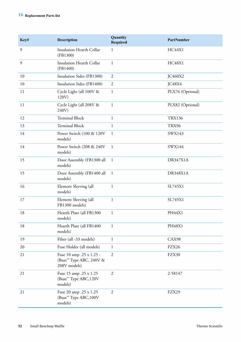
16 Replacement Parts list
Replacement Parts list
Key# DescriptionQuantityRequired
PartNumber
1 Cordset (240V EUROPEAN)
1 CR1058X1
1 Cordset (120V) 1 CR1142X1
1 Cordset (240V USA) 1 CR1142X3
50 Small Benchtop Muffle Thermo Scientific

16 Replacement Parts list
1 Cordset (240V CHINA) 1 CR1284X1
1 Heating element (100V - FB1314M)
1 EL140X2
1 Heating element (120V - FB1315M)
1 EL44X1
1 Heating element (208V - FB1318M)
1 EL44X3
1 Heating element (240V - FB1310M, -33)
1 EL44X2
1 Heating element (100V - FB1414M)
1 EL186X2
1 Heating element (120V - FB1415M)
1 EL48X1
1 Heating element (208V - FB1418M)
1 EL48X3
1 Heating element (240V - FB1410M, -33)
1 EL48X2
2 Thermocouple (FB1300 models)
1 TC1256X1
2 Thermocouple (FB1400 models)
1 TC746X1A
3 Solid State Relay (all models) 1 RYX34
4 Door Switches (all models) 2 SWX163
5 Control (FB1300M & FB1400M models except FB1410M-33)
1 CN71X184
5 Control (FB1410M-33 model only)
1 CN71X169
6 Insulation Btm (all FB1300 models)
1 JC44X1
6 Insulation Btm (all FB1400 models)
1 JC48X2
7 Insulation Back (all FB1300 models)
1 JC44X4
7 Insulation Back (all FB1400 models)
1 JC48X1
8 Insulation Top (all FB1300) 1 JC44X3
8 Insulation Top (all FB1400) 1 JC48X3
Key# DescriptionQuantityRequired
PartNumber
Thermo Scientific Small Benchtop Muffle 51
16 Replacement Parts list
9 Insulation Hearth Collar (FB1300)
1 HC44X1
9 Insulation Hearth Collar (FB1400)
1 HC48X1
10 Insulation Sides (FB1300) 2 JC460X2
10 Insulation Sides (FB1400) 2 JC48X4
11 Cycle Light (all 100V & 120V)
1 PLX76 (Optional)
11 Cycle Light (all 208V & 240V)
1 PLX82 (Optional)
12 Terminal Block 1 TRX136
13 Terminal Block 1 TRX96
14 Power Switch (100 & 120V models)
1 SWX143
14 Power Switch (208 & 240V models)
1 SWX144
15 Door Assembly (FB1300 all models)
1 DR347X1A
15 Door Assembly (FB1400 all models)
1 DR348X1A
16 Element Sleeving (all models)
1 SL745X1
17 Element Sleeving (all FB1300 models)
1 SL745X1
18 Hearth Plate (all FB1300 models)
1 PH44X1
18 Hearth Plate (all FB1400 models)
1 PH48X1
19 Filter (all -33 models) 1 CAX98
20 Fuse Holder (all models) 1 FZX26
21 Fuse 10 amp .25 x 1.25 - (Buss™ Type ABC, 240V & 208V models)
2 FZX30
21 Fuse 15 amp .25 x 1.25 (Buss™ Type ABC,120V models)
2 2-58147
21 Fuse 20 amp .25 x 1.25 (Buss™ Type ABC,100V models)
2 FZX29
Key# DescriptionQuantityRequired
PartNumber
52 Small Benchtop Muffle Thermo Scientific

16 Replacement Parts list
22 Dial Plate Label (FB1300) 1 DLX248
22 Dial Plate Label (FB1400) 1 DLX249
Key# DescriptionQuantityRequired
PartNumber
Thermo Scientific Small Benchtop Muffle 53

16 Replacement Parts list
54 Small Benchtop Muffle Thermo Scientific

Important
For your future reference and when contacting the factory, please have the following information readily available:
Model Number:
Serial Number:
Date Purchased:
The above information can be found on the dataplate attached to the equipment. If available, please provide the date purchased, the source of purchase (manufacturer or specific agent/rep organization), and purchase order number.
IF YOU NEED ASSISTANCE:
LABORATORY PARTS and SERVICE
Phone: 800/438-4851
FAX: 828/658-2576
TECHNICAL SUPPORT
Phone: 800/438-4851

© 20term
the
The275AshUniwww
18 Thermo Fisher Scientific Inc. All rights reserved. All trademarks are the property of Thermo Fisher Scientific Inc. and its subsidiaries. Specifications, s and pricing are subject to change. Not all products are available in all countries. Please consult your local sales representative for details.
rmoscientific.com
LT1256X1 Rev.G
rmo Fisher Scientific Inc. Aiken Roadeville, NC 28804ted States
.thermofisher.com