Thermal Protection Systems for Reusable Launch … Protection Systems for Reusable Launch Vehicles...
61
Thermal Protection Systems for Reusable Launch Vehicles Max Blosser Short Course: Thermal Control Hardware Thermal & Fluids Analysis Workshop Hampton, VA August 22, 2003
-
Upload
hoangtuong -
Category
Documents
-
view
224 -
download
2
Transcript of Thermal Protection Systems for Reusable Launch … Protection Systems for Reusable Launch Vehicles...

Thermal Protection Systems for Reusable Launch Vehicles
Max Blosser
Short Course: Thermal Control Hardware
Thermal & Fluids Analysis WorkshopHampton, VA
August 22, 2003

OUTLINE
• Introduction
• Fundamentals of Aerodynamic Heating
• Approaches to Thermal Protection
• Metallic TPS
• Current TPS Research
• Integrated Multifunctional Structures

INTRODUCTION

INTRODUCTIONKEY TECHNOLOGIES FOR REUSABLE LAUNCH VEHICLES
Critical RLV Technologies• More efficient propulsion• Reusable cryogenic fuel tanks• Improved thermal protection systems
TPS for RLV’s
• Large vehicle surface area
• Integration with vehicle structure
• Long life
• Rapid turnaround
TPS Design Goals
• Increase- Operability- Durability- Capability
• Decrease- Mass- Cost- Risk

INTRODUCTIONTPS DEVELOPMENT: A MULTIDISCIPLINARY CHALLENGE
Required Disciplines
• Aerothermodynamics• Structures• Materials• Heat transfer • Vehicle systems• Acoustics• Fatigue and creep• Panel flutter• Manufacturing• Testing
Interactions
• Thermal-structural- Structural support often undesirable heat short- Thermal expansion -> stresses and deformations- Material properties change with temp. & press.
• Surface deformations may affect aerothermal heating• Chemical changes (oxidation) degrade material • Sizing TPS and structure separately not optimal

AERODYNAMIC HEATING FUNDAMENTALS

AERODYNAMIC HEATING FUNDAMENTALSAERODYNAMIC HEATING OF TPS
Flow Phenomena• Free molecular to continuum flow regimes• Shock waves, shock interactions• Convective and radiative heating• Laminar to turbulent boundary layer transition
Vehicle Geometry• Windward and leeward surfaces• Stagnation region, leading-edge radius
Interaction with Vehicle Surface• Radiation equilibrium temperature• Integrated heat load• Surface emittance, catalysis and oxidation• Surface roughness, steps, gaps, bowing
Heating Prediction• Engineering codes• Computational aerothermodynamics
Trajectory• Rocket vs. airbreathing propulsion• Quick, hot vs. longer, cooler trajectories

AERODYNAMIC HEATING FUNDAMENTALSFLOW REGIMES

AERODYNAMIC HEATING FUNDAMENTALSSHOCK WAVES
Oblique Shock Wave
M2
Vehicle surface
M1
p1
p2
T1T2
Normal Shock• Supersonic to subsonic flow (M2>1)• Increase in pressure and temperature
Oblique Shock• Parallel and normal components• Calculate pressure and temperature changes for normal component• M2 can be supersonic

AERODYNAMIC HEATING FUNDAMENTALSCONVECTIVE AND RADIATIVE HEATING
Radiation
Convection
Vehicle surface

AERODYNAMIC HEATING FUNDAMENTALSAERODYNAMIC HEATING OF TPS
2000
1800
1600
1400
1200
1000
SurfaceTemperature, K
0.001 0.01 0.1 1
Recombination Efficiency
Emittanceε =0.95ε =0.80ε =0.60ε =0.40
Flow ConditionsMach No. = 3.7Enthalpy = 7.5 MJ/kgPwall = 850 Pa
O22O
Shock wave
Vehicle surfaceO+O =O2 + heat
Dissociation Recombination
• Both oxygen and nitrogen can be dissociated when passing through a shock wave• If the vehicle surface acts as a catalyst for recombination, additional surface
heating can result

AERODYNAMIC HEATING FUNDAMENTALSBOUNDARY LAYERS
Laminar-to-Turbulent Boundary Layer Transition• Flow is usually laminar for high altitude, high enthalpy flow• Aerodynamic heating can be several times higher for turbulent flow• Rough surface can cause premature transition to turbulent flow• TPS design seeks to minimize surface roughness

AERODYNAMIC HEATING FUNDAMENTALSPROPULSION EFFICIENCIES
SpecificImpulse, s

AERODYNAMIC HEATING FUNDAMENTALSPROPULSION IMPACTS RLV CONFIGURATION
Rocket Airbreathing

Windward Surface
Leeward Surface
AERODYNAMIC HEATING FUNDAMENTALSHEATING VARIATION OVER A VEHICLE
APPROACHES TO THERMAL PROTECTION

HEAT SINK STRUCTURE INSULATED STRUCTURE
COOLANTFLOW
AIR FLOW
FILM COOLING CONVECTIVE COOLING
PASSIVE:
ACTIVE:
S URFACEHEATING
RADIATION
HOT STRUCTURE
S URFACEHEATING
S URFACEHEATING
RADIATION
RADIATION
CONDUCTIONINSULATION
STRUCTURE
S URFACEHEATING
RADIATIONS URFACEHEATING
COOLANTFLOW
ABLATION
AIR FLOW
ABLATOR
AIR FLOW
TRANSPIRATION COOLING
COOLANTFLOW
SEMI- PASSIVE:
S URFACEHEATING
S URFACEHEATING
HEAT PIPE
RADIATION
S URFACEHEATING
WORKINGFLUID
STRUCTURE
APPROACHES TO THERMAL PROTECTIONTYPES OF THERMAL PROTECTION SYSTEMS
PreferredRLV approach
Choose the simplest and/or lightest that works

APPROACHES TO THERMAL PROTECTIONHEAT SINK STRUCTURE
700
600
500
400
300
200
100
0120010008006004002000
MaterialHeat
Capacity,BTU/lbm
Temperature, °F
Initial Temperature = 80°F
AluminumCarbon/carbon
Beryllium
EncapsulatedPhase ChangeMaterial
Graphitepolyimide
Iron
NickelChromiumTitanium
Carbon/SiCRange of Applicability Depends on:• Integrated heat load• Structural heat capacity• Allowable structural temperature limits• Structural heat loss mechanisms
•The heat sink approach is generally practical for only very short heating pulses
• Not appropriate for RLV’s
X-15 WING STRUCTURE
HEAT STORAGE IN STRUCTURES

APPROACHES TO THERMAL PROTECTIONHOT STRUCTURE
4000
3500
3000
2500
2000
1500
1000
500
0100806040200
RadiationEquilibrium
Temperature, °F
Surface Heat Flux, BTU/ft2/s
Emittance0.1 0.3 0.5 0.6
0.81.0
Hot Structure:• Radiation equilibrium at surface
(qin = qout)• Can reach steady state• High temperature material• Temp. gradients, thermal stresses• Interfaces to cooler structures• Large integrated heat loads
Applications:• Supersonic cruise• Lightly loaded RLV structures
(control surfaces)

APPROACHES TO THERMAL PROTECTIONTPS INSULATING STRUCTURE
INSULATED STRUCTURE
SURFACE HEATING
RADIATION
CONDUCTIONINSULATION
STRUCTURE
Surface acts like hot structure• Near radiation equilibrium temperature• Reradiates most of incident heat• Allows some heat to reach structure
Structure acts like a heat sink• Integrated heat load through TPS• Structural heat capacity• Allowable structural temperature limits• Structural heat loss mechanisms
Applications:• Space Shuttle Orbiter• Future RLV’s

APPROACHES TO THERMAL PROTECTIONTPS CONCEPTS VARY OVER VEHICLE SURFACE

APPROACHES TO THERMAL PROTECTIONHEAT PIPE
Superalloy heat pipeleading edge for Shuttle wing
Operating liquidmetal heat pipe
Heat Pipe Operation• Sealed tubes containing working fluid• Saturated wick lines interior• Localized heating evaporates liquid• Vapor travels to cooler region and condenses• Liquid returns to hot spot through wick• No pumps, sensors, or controls required
Heat Pipe Applications• Diffuses a local hot spot• Wing leading edges• Nose capsCarbon/carbon heat
pipe leading edge for NASP wing

APPROACHES TO THERMAL PROTECTIONABLATION
Apollo Capsule
Ablator Operation• Partially consumed by heating• Heat absorbed as gases generated• Gases block convective heating• Ablator is also insulator• Surface recedes with time• Non-reusable
Ablator Applications• Can accommodate very high heating rates• Hot side of ballistic reentry capsules (Apollo)• Planetary probes• Missile nose caps• Less attractive for large areas on RLV’s

APPROACHES TO THERMAL PROTECTIONTRANSPIRATION/FILM COOLING
Transpiration and Film Cooling• Coolant is injected into the boundary layer
• Porous surface – transpiration• Discrete slots – film cooling
• Prevents direct contact with hot flow• Removes heat from structure• Can accommodate large heating rates
Applications of Transpiration and Film Cooling• Not mass-efficient for large areas• Complex system, have to carry coolant• Localized areas• Nose tips• Possibly sharp leading edges• Airbreathing engine structures
Transpiration-cooled nose tip
Hot gas
Coolant
Cool boundarylayer
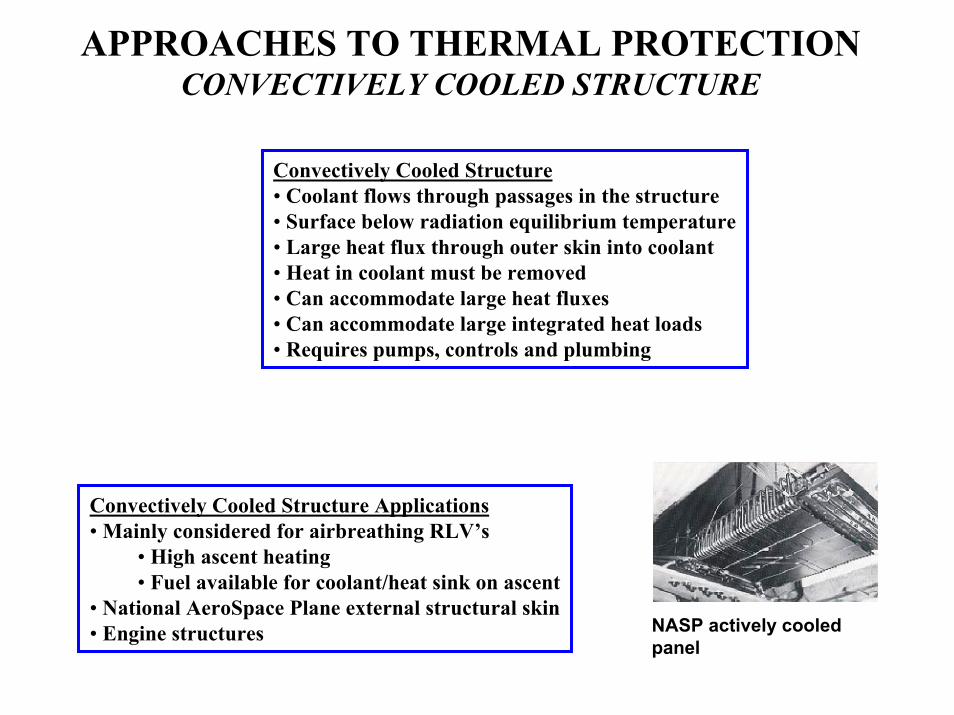
APPROACHES TO THERMAL PROTECTIONCONVECTIVELY COOLED STRUCTURE
Convectively Cooled Structure• Coolant flows through passages in the structure• Surface below radiation equilibrium temperature• Large heat flux through outer skin into coolant• Heat in coolant must be removed• Can accommodate large heat fluxes• Can accommodate large integrated heat loads• Requires pumps, controls and plumbing
Convectively Cooled Structure Applications• Mainly considered for airbreathing RLV’s
• High ascent heating• Fuel available for coolant/heat sink on ascent
• National AeroSpace Plane external structural skin• Engine structures NASP actively cooled
panel

METALLIC THERMAL PROTECTION SYSTEMS

METALLIC TPSMOTIVATION FOR DEVELOPMENT
Candidate TPS
• Ceramics- Tiles- Blankets
• Ceramic Matrix Composites (CMC’s)• Metallic panels
Metallic TPS• Ductile/damage resistant• Mass efficient foil structures/insulations• Much lower maintenance• No re-waterproofing between flights

METALLIC TPSTECHNOLOGY DEVELOPMENT
MATERIALS CHARTERIZATION/IMPROVEMENT
CONCEPT DEVELOPMENT
METALS• Structural properties
• Surface properties
INSULATIONS• Measured thermal properties
• Validated analysis
• Optimized combinations
CONCEPT DEFINITION
• Conception, design and analysis
• Vehicle integration
CONCEPT EVALUATION
• Coupon tests
• Panel tests

METALLIC TPS: MATERIALS HIGH PERFORMANCE METALS FOR TPS
Temperature, ºF500 1000 1500 2500 350030002000
500 1000 1500 2000
RelativeStrength
Oxidation Stability Oxidation Protective Coatings Required
TitaniumComposites
ConventionalTitanium
Alloys
Superalloys
Refractory Metals
Aluminum alloysAluminumComposites
AdvancedTitanium Alloys
γ− Titanium Aluminide Alloys
DispersionStrengthenedSuperalloys
Temperature, ºC

METALLIC TPS : MATERIALS SURFACE PROPERTIES
Effects of Emittance and CatalyticEfficiency
Desired Surface Properties
2000
1800
1600
1400
1200
1000
SurfaceTemperature,
K
0.001 0.01 0.1 1
Catalytic Efficiency
Emittanceε =0.95ε =0.80ε =0.60ε =0.40
Flow ConditionsMach No. = 3.7Enthalpy = 7.5 MJ/kgPwall = 850 Pa
• Oxidation protection• Emittance > 0.8• Catalytic Efficiency - low as possible• Reflectance - high in 1-2.5 µm range
Achieving desired surface properties may require coatings
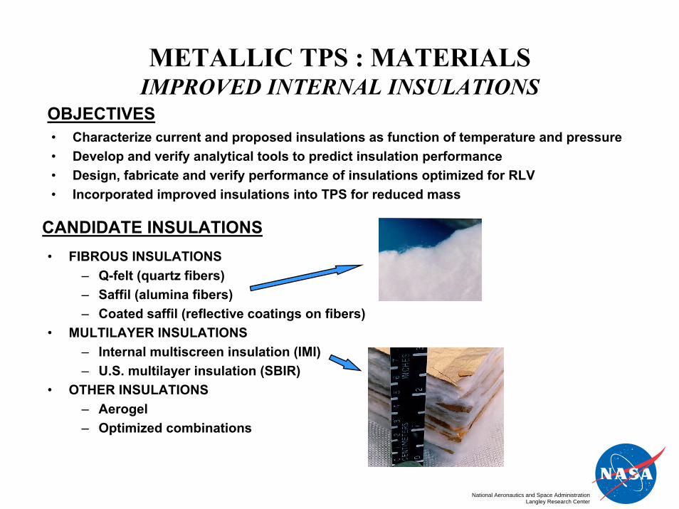
METALLIC TPS : MATERIALS IMPROVED INTERNAL INSULATIONS
OBJECTIVES• Characterize current and proposed insulations as function of temperature and pressure• Develop and verify analytical tools to predict insulation performance• Design, fabricate and verify performance of insulations optimized for RLV• Incorporated improved insulations into TPS for reduced mass
CANDIDATE INSULATIONS• FIBROUS INSULATIONS
– Q-felt (quartz fibers)– Saffil (alumina fibers)– Coated saffil (reflective coatings on fibers)
• MULTILAYER INSULATIONS– Internal multiscreen insulation (IMI)– U.S. multilayer insulation (SBIR)
• OTHER INSULATIONS– Aerogel– Optimized combinations
National Aeronautics and Space AdministrationLangley Research Center

METALLIC TPS: CONCEPTSEARLY TPS CONCEPTS
Metallic Standoff TPS
Metallic TPS Dev
TitaniumMultiwall ACC Multipost
elopment
National Aeronautics and Space AdministrationLangley Research Center
SuperalloyHoneycomb

METALLIC TPS : CONCEPTS RECENT TPS CONCEPTS
Superalloy Honeycomb TPS
Felt/RTV seal
Inconel 617 beaded side walls
Inner titanium honeycomb sandwich
Mechanical fastener
Outer Inconel 617 honeycomb sandwich Saffil insulation
12 in.-square panel12 in.-square panelOverlapping gap cover
Foil encapsulatedinsulation
Attachment standoffbrackets External cryotank
stiffeners
Outer metallichoneycomb
Fastener accesscovers
Panel-to-panel seal
X-33 Windward Metallic TPS

METALLIC TPS : CONCEPTSARMOR TPS CONCEPT
Features• Compliant sides
- Decouple h/c and frame - Can bulge to fill gap
• Stiffened corners accommodatethermal expansion mismatch
• Insulated fasteners• Subsurface seals (felt gasket under
panel perimeter)• Fastener access from outer surface• Encapsulated insulation
Titanium frame
Compliant foil side
Outer h/c sandwich
Overlappingseal
Insulation and lower Ti foil not shown
Support bracket
Fastener access tube
Slotted holes for fasteners
Fastener access covers
Outer Surface
Inner Surface

METALLIC TPS : CONCEPTSSIZING OF SLOTTED HOLES IN ARMOR TPS
• Slotted holes were used for tank/TPS strain mismatch
• One corner of each panel was fixed and the others could move
• 14 load conditions
considered– Tank pressures– TPS temperatures– Tank temperatures
Fixed PointFixed Point

METALLIC TPS : CONCEPTSSUPPORT BRACKETS IN ARMOR TPS
• Free thermal expansion of outer honeycomb layer
• Beaded to resist buckling• Thin to reduce heat short• Shear stiffness• Critical structural element

METALLIC TPS : CONCEPTSARMOR TPS INTEGRATED WITH CRYOGENIC TANK
TEEK Cryogenic foam
Cryogenic tankStructure
ARMOR TPS panelTPS support structure

METALLIC TPS : CONCEPTSFULLY ASSEMBLED ARMOR TPS PANEL
Four ARMOR TPS panels average 2.4 lb/ft2

METALLIC TPS : ANALYSISTHERMAL MODELING
Thermal Analysis• Transient Thermal Problem
- Surface temperatures vary from ambient to over 2000°F- Pressure varies from near vacuum to 1 atmosphere- Re-entry flight approximately 1/2 hour- Insulation sized to limit structural temperature
• Nonlinear Material Properties- Most TPS material thermal properties strongly temperature dependent- Insulation conductivity strongly pressure and temperature dependent- Gas conductivity in internal voids is complex- Heat transfer through honeycomb sandwich involves multiple modes
INSULATED STRUCTURE
SURFACE HEATING
RADIATION
CONDUCTIONINSULATION
STRUCTURE
Desired Features of Thermal Model• Accuracy: includes all important modes of heat transfer • Flexibility: easily modified to represent modeling and design variations• Efficiency: suitable for large numbers of iterative calculations
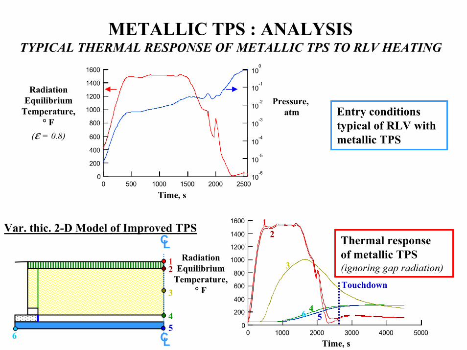
METALLIC TPS : ANALYSISTYPICAL THERMAL RESPONSE OF METALLIC TPS TO RLV HEATING
1600
1400
1200
1000
800
600
400
200
025002000150010005000
10-6
10-5
10-4
10-3
10-2
10-1
100
RadiationEquilibrium
Temperature,° F
(ε = 0.8)
Time, s
Pressure, atm Entry conditions
typical of RLV withmetallic TPS
CL
CL
1600
1400
1200
1000
800
600
400
200
0500040003000200010000
RadiationEquilibrium
Temperature,° F
Time, s
Thermal responseof metallic TPS(ignoring gap radiation)1
2
12
3
3
44
55
6
6
Touchdown
Var. thic. 2-D Model of Improved TPS
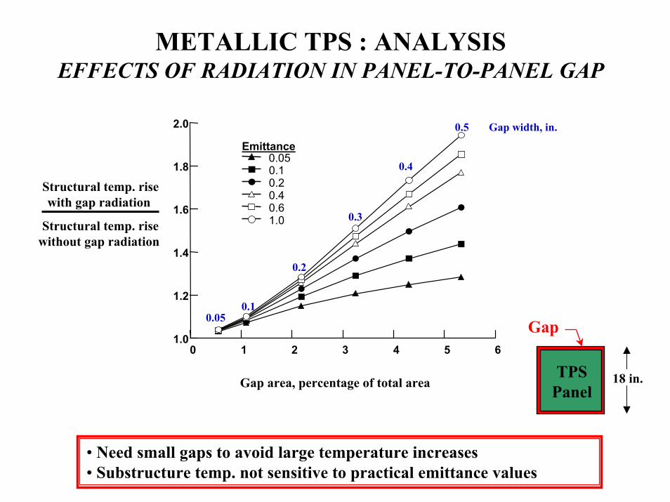
METALLIC TPS : ANALYSISEFFECTS OF RADIATION IN PANEL-TO-PANEL GAP
Gap area, percentage of total area
Emittance0.050.10.20.40.61.0
2.0
1.8
1.6
1.4
1.2
1.06543210
TPSPanel
Gap0.05
0.5
0.1
0.2
0.4
0.3
Gap width, in.
18 in.
Structural temp. risewith gap radiation
Structural temp. risewithout gap radiation
• Need small gaps to avoid large temperature increases• Substructure temp. not sensitive to practical emittance values

CURRENT THERMAL PROTECTION SYSTEMS RESEARCH

CURRENT TPS RESEARCHCERAMIC BLANKETS
• DuraFRSI – AFRSI blanket with a metal foil outer surface
• CRI – blanket with rigidized outer surface
• High temperature FRSI (felt)

CURRENT TPS RESEARCHCERAMIC TILES
• AETB tile with TUFI/cgs coating
• BRI – improved toughness, conductivity comparable to HRSI
• Tile leading edges
• Hybrid tiles with CMC outer layer
• SHARP leading edges – high temperature ceramics

CURRENT TPS RESEARCHCERAMIC MATRIX COMPOSITE TPS
• X-33 Phase I C/SiC heat shield (1 ft x 4 ft)

CURRENT TPS RESEARCHCERAMIC MATRIX COMPOSITE HOT STRUCTURES
• NASP control surface component
• X-33 body flap – incomplete design
• X-38 control surface
• X-37 control surface

CURRENT TPS RESEARCHMETALLIC TPS
• X-33 windward TPS – full vehicle TPS including seals and penetrations
• ARMOR TPS prototype panels
• Oceaneering metallic TPS

INTEGRATED MULTIFUNCTIONAL STRUCTURES
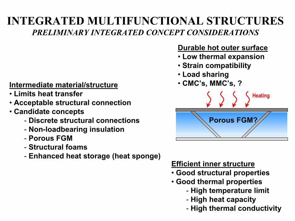
INTEGRATED MULTIFUNCTIONAL STRUCTURESPRELIMINARY INTEGRATED CONCEPT CONSIDERATIONS
Durable hot outer surface• Low thermal expansion• Strain compatibility• Load sharing• CMC’s, MMC’s, ?Intermediate material/structure
• Limits heat transfer• Acceptable structural connection• Candidate concepts
- Discrete structural connections- Non-loadbearing insulation- Porous FGM- Structural foams- Enhanced heat storage (heat sponge)
Heating
Porous FGM?
Efficient inner structure• Good structural properties• Good thermal properties
- High temperature limit- High heat capacity- High thermal conductivity

INTEGRATED MULTIFUNCTIONAL STRUCTURESINITIAL GENERIC SANDWICH CONCEPTS
Foam-core Sandwich Truss-core Sandwich
Hot outer surface
Cooler inner surface
• Insulating structural foam core– High temperature capability– Strain capability comparable to
structural facesheets– Strength to perform as sandwich
core– Low conductivity
• Truss core– Discrete connections between the
hot and cool facesheets– Acceptable structural connections– Acceptable heat shorts
• Insulation– Load-bearing or non-load-bearing

700
600
500
400
300
200
100
0120010008006004002000
MaterialHeat
Capacity,BTU/lbm
Temperature, °F
Initial Temperature = 80°F
AluminumCarbon/carbon
Beryllium
G ra p h ite c o m p o s ite
Iron
NickelChromiumTitanium
Carbon/SiC
L ith iu mHeat Sponge
• High heat capacity inner structure can reduce required insulation• Heat capacity enhancement may be lighter than additional insulation• Patent disclosure filed on Heat Sponge
INTEGRATED MULTIFUNCTIONAL STRUCTURESHEAT CAPACITY OF STRUCTURAL MATERIALS

INTEGRATED MULTIFUNCTIONAL STRUCTURESTHERMAL/STRUCTURAL SIZING METHOD
INPUT PROCESS CONSTRAINTS
StructuralAnalysis
Converged? no
yes
• Max. stress• Max. strain• Deflection limits• Buckling
Global OptimizerThermal/Struct Sizing
• Minimize mass
ThermalAnalysis
• Material temperature limits• Temperature gradients• Overall thickness?
Material propertiesand geometry
AerothermalLoads
Temperatures
StructuralLoads
OUTPUT
Dimensions, mass, temperatures, etc.

INTEGRATED MULTIFUNCTIONAL STRUCTURESHIGH THERMAL CONDUCTIVITY STRUCTURAL MATERIALS
t
High k inner structure
• Large panels with variations in heating over surface• High thermal conductivity inner structure:
– Enables uniform thickness panel sized for average heat load– No need to taper insulation thickness for local variations in
heating– Reduces temperature gradients (and thermal stress/distortions)
on inner surface– Allows all of inner structure to approach temperature limits
and use all available heat capacity

SUPPLEMENTAL SLIDES

METALLIC TPS : ANALYSISTHERMAL CONDUCTIVITY OF A GAS IN A CAVITY
c
gg
L
kk
λγ
γα
αPr1
12221
*
+
−+=
Pd 2TK
2g
Bπ
λ =
*gk - Thermal conductivity at 1 atm
Pr – Prandtl NumberLc – characteristic lengthα – accommodation coefficientγ – ratio of specific heatsλ – mean free path
P – pressureT – temperatureKB – Boltzman constantdg– gas collision diameter
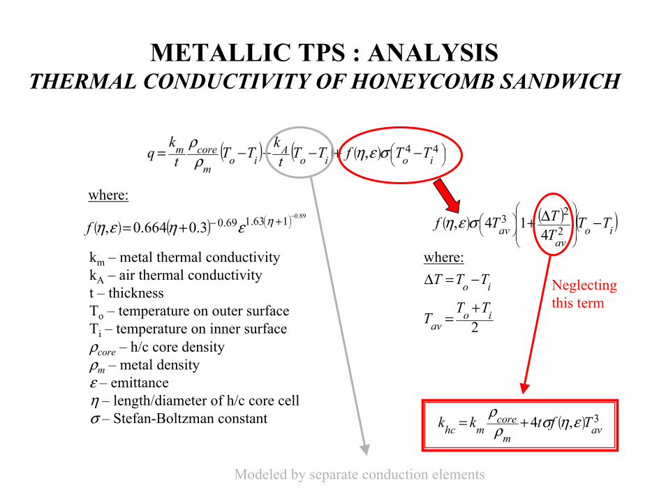
METALLIC TPS : ANALYSISTHERMAL CONDUCTIVITY OF HONEYCOMB SANDWICH
( ) ( ) ( )
−+−+−= 44, ioio
Aio
m
corem TTfTTtk
TTtk
q σεηρρ
( ) ( )89.0163.169.03.0664.0,
−
+−+= ηεηεηf ( ) ( ) ( )io
avav TT
TTTf −∆+
2
23
414, σεη
2io
avTT
T+
=
io TTT −=∆
( ) 3,4 avm
coremhc Tftkk εησρ
ρ+=
where:
Neglecting this term
where:
km – metal thermal conductivitykA – air thermal conductivityt – thicknessTo – temperature on outer surfaceTi – temperature on inner surfaceρcore – h/c core densityρm – metal densityε – emittanceη – length/diameter of h/c core cellσ – Stefan-Boltzman constant
Modeled by separate conduction elements
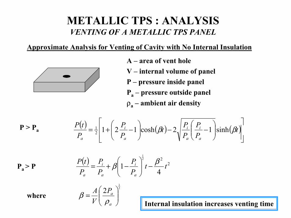
METALLIC TPS : ANALYSISVENTING OF A METALLIC TPS PANEL
Approximate Analysis for Venting of Cavity with No Internal Insulation
A – area of vent holeV – internal volume of panelP – pressure inside panelPa – pressure outside panelρa – ambient air density
( ) ( ) ( )
−−
−+= t
PP
PPt
PP
PtP
a
i
a
i
a
i
a
ββ sinh12cosh12121P > Pa
( ) 22
41
21
ttPP
PP
PtP
a
i
a
i
a
ββ −
−+=Pa > P
21
2
=
a
aPVA
ρβwhere
Internal insulation increases venting time

METALLIC TPS : ANALYSISTHERMAL STRESS AROUND A CYLINDRICAL FASTENER
Pffr −== θσσ
( )( )
−
−−=
1
12
2
abrb
Psr
σ
a
b
Fastener
Fastener
Structure
r Structure
( )( )
−
−=
1
12
2
abrb
Psθσ
( )
( ) ( ) ( )ff
sss
sfs
ab
EE
ab
TabE
Pννν
αα
−
−
+−++
∆−
−
=1111
1
22
2
Where

METALLIC TPS : ANALYSISFREE THERMAL BOWING OF A SANDWICH PANEL
Sandwich Panel With Facesheets at Different Temperatures
δΤ1
Τ2
( )( ) ( )
−−
−
+= 22112211
11
2cos11 TT
tL
TTTt αα
αααδ
α2
α1tΤ0
Panel bows into a spherical segmentL
Simplifying: if and111 <<Tα ααα == 21
( ) tTL
tTL
Tt
82cos1
2 ∆≈
∆−
∆
= ααα
δthen

METALLIC TPS : MATERIALS OPTIMUM INSULATION FOR STEADY STATE HEAT TRANSFER
Ttkq ∆=
ρtAm =
qTkA
m ∆= ρ
Minimize mass
Required thermal resistance
Minimize
Insulation
k – thermal conductivityρ – densityq – heat fluxm – massA – areaT – temperaturet - thickness
∆T, qt
Minimize ρk for minimum mass insulation in steady state

METALLIC TPS : MATERIALS MEASURED INSULATION PERFORMANCE
• The product of density and conductivity is a good indicator ofinsulation mass efficiency for steady state heat transfer(transient case more complicated)
• Saffil (alumina) and Q-felt (quartz) fibrous insulations have similarthermal performance at a given density
• Insulations with multiple reflective layers offer improved performance
4
3
2
1
010008006004002000
Insulation ρ (lbm/ft3) saffil 1.5 saffil 3 saffil 6 q-fiber 3 q-fiber 6 multi-layer 1 1.5 multi-layer 2 3 multi-layer 3 3
4
3
2
1
010008006004002000
ρ ∗ k,
FfthrinBtu
ftlbm
23 °⋅⋅⋅⋅
Average temperature, oF Average temperature, oF
Pressure = 10-3 torrLittle gas conduction
Pressure = 100 torrGas conduction important