Reusable Launch Vehicle - Structural Analysis of Variable ...
13
International Research Journal of Engineering and Technology (IRJET) e-ISSN: 2395-0056 Volume: 08 Issue: 09 | Sep 2021 www.irjet.net p-ISSN: 2395-0072 © 2021, IRJET | Impact Factor value: 7.529 | ISO 9001:2008 Certified Journal | Page 1339 Reusable Launch Vehicle - Structural Analysis of Variable Landing Gear Mechanism P M S S Manohar 1 , P Esther Nirmala 1 , K Rohith Kumar 1 , Kajal gupta 2 , Aditi bhatt 2 , Jainul Abedin 2 1 Student, Hindustan Institute of Technology and Science, Tamil Nadu, India. 2 Supervisor, Department of Research and Development, Abyom SpaceTech and Defense Pvt. Ltd, Uttar Pradesh, India ---------------------------------------------------------------------***---------------------------------------------------------------------- Abstract - Efforts are being taken to make space missions more affordable. Reusable Launch Vehicle (RLV) is one such innovation aimed to reduce the manufacturing costs drastically. Developments are being made to make improvements on the already existing landers and also to make the full rocket reusable. This article examines the present state of the technology for reusable launch vehicles. and also aims to provide an enhancement to the already existing landing legs used on reusable launch vehicles (RLV) which can help the rocket land on uneven surfaces. This landing mechanism employs honeycomb shock absorber to absorb the energy during landing. The main purposefulness of this idea is to avoid the moment which topples the rocket during landing on uneven terrain. The paper also provides results from various analyses conducted to support the proposed idea. Key Words: Reusable Launch Vehicle, landing gear, structural analysis, flight profile of RLV, honeycomb shock absorber, uneven terrain landing, variable landing gear. 1. INTRODUCTION The international space market has been increasing tremendously over the last few decades. Developments are being made for more accuracy, more efficiency and higher performance of the space vehicles. Most notable recent advancement is the Reusable Launch Vehicle (RLV). In Reusable launch vehicles, the first stage is reignited after the stage separation, and then it heads back and lands on a target. RLVs help reduce total launch cost drastically. It is estimated to reduce the cost by approximately 70% for the total launch with only costs of inspection and re-fuelling for the first stage. This makes space more affordable for the general public as the transportation costs reduce. With increased space exploration, we could discover many resources like rare isotopes, materials, etc., which are abundant elsewhere in space. RLVs reduce the consumption of the materials for manufacturing thus, it’s a more sustainable option. With resources and raw materials depleting over the years we could save huge amounts of materials like titanium alloys, aluminium, etc., by reusing the first stage and not having to build one for every launch. RLVs reduce the manufacturing time greatly. The time taken to build the first stage of the rocket takes approximately 18 months. With a reusable first stage, the manufacturing time is reduced drastically making space visits more frequent. 2. LITERATURE REVIEW Rojas et al. the launch vehicle is re-entering the atmosphere and that can be achieved by retro propulsion or enhancing the aerodynamic drag on the body of the launch vehicle with the help of the atmosphere which will decelerate the launch vehicle. It makes use of a combination of multiple systems. Retro propulsion was also used in 1969 for the Apollo mission when man successfully landed on the moon. Return flight orbital vehicles are relatively costlier and more complex. Return flight vehicle was first used in the space shuttle Orbiter. The main advantage of the return flight orbital vehicles is that they can return to the place where they were deployed. But, the return flight orbital vehicle will be affected by the environmental conditions as it depends in the atmosphere for its descent. . Another type of launch vehicle components recovery is using external recovery systems like the Hypersonic Inflatable Aerodynamic decelerator (HIAD) technology which is basically a parachute which can withstand extreme conditions. This type of recovery system is light weight and can be installed efficiently. This parachute essentially slows down the speed of the descending launch vehicle components but to attain complete recovery it needs the support of other recovery systems. The main components used in the reusability systems are cold gas thrusters, four hypersonic grid fins for three axis control and four deployable landing legs. The cold gas thrusters help in orienting the launch vehicle for proper descent. The system consists of gas in a pressurized tank and a valve regulates the flow of the gas through a nozzle generating a force. The cold gas thrusters are mainly employed for control and are reliable. But the tank can occupy a lot of space and volume in the vehicle. The grid fins are used to steer the rocket as it descends. They are used at both subsonic and supersonic speeds and allow precise orientation and control. The grid fins are generally made
Transcript of Reusable Launch Vehicle - Structural Analysis of Variable ...
International Research Journal of Engineering and Technology (IRJET) e-ISSN: 2395-0056
Volume: 08 Issue: 09 | Sep 2021 www.irjet.net p-ISSN: 2395-0072
© 2021, IRJET | Impact Factor value: 7.529 | ISO 9001:2008 Certified Journal | Page 1339
Reusable Launch Vehicle - Structural Analysis of Variable Landing Gear
Mechanism
P M S S Manohar1, P Esther Nirmala1, K Rohith Kumar1, Kajal gupta2, Aditi bhatt2, Jainul
Abedin2
1Student, Hindustan Institute of Technology and Science, Tamil Nadu, India. 2Supervisor, Department of Research and Development, Abyom SpaceTech and Defense Pvt. Ltd,
Uttar Pradesh, India ---------------------------------------------------------------------***----------------------------------------------------------------------Abstract - Efforts are being taken to make space missions more affordable. Reusable Launch Vehicle (RLV) is one such innovation aimed to reduce the manufacturing costs drastically. Developments are being made to make improvements on the already existing landers and also to make the full rocket reusable. This article examines the present state of the technology for reusable launch vehicles. and also aims to provide an enhancement to the already existing landing legs used on reusable launch vehicles (RLV) which can help the rocket land on uneven surfaces. This landing mechanism employs honeycomb shock absorber to absorb the energy during landing. The main purposefulness of this idea is to avoid the moment which topples the rocket during landing on uneven terrain. The paper also provides results from various analyses conducted to support the proposed idea.
Key Words: Reusable Launch Vehicle, landing gear, structural analysis, flight profile of RLV, honeycomb shock absorber, uneven terrain landing, variable landing gear.
1. INTRODUCTION The international space market has been increasing tremendously over the last few decades. Developments are being made for more accuracy, more efficiency and higher performance of the space vehicles. Most notable recent advancement is the Reusable Launch Vehicle (RLV). In Reusable launch vehicles, the first stage is reignited after the stage separation, and then it heads back and lands on a target. RLVs help reduce total launch cost drastically. It is estimated to reduce the cost by approximately 70% for the total launch with only costs of inspection and re-fuelling for the first stage. This makes space more affordable for the general public as the transportation costs reduce. With increased space exploration, we could discover many resources like rare isotopes, materials, etc., which are abundant elsewhere in space. RLVs reduce the consumption of the materials for manufacturing thus, it’s a more sustainable option. With resources and raw materials depleting over the years we could save huge amounts of materials like titanium alloys,
aluminium, etc., by reusing the first stage and not having to build one for every launch. RLVs reduce the manufacturing time greatly. The time taken to build the first stage of the rocket takes approximately 18 months. With a reusable first stage, the manufacturing time is reduced drastically making space visits more frequent.
2. LITERATURE REVIEW Rojas et al. the launch vehicle is re-entering the atmosphere and that can be achieved by retro propulsion or enhancing the aerodynamic drag on the body of the launch vehicle with the help of the atmosphere which will decelerate the launch vehicle. It makes use of a combination of multiple systems. Retro propulsion was also used in 1969 for the Apollo mission when man successfully landed on the moon. Return flight orbital vehicles are relatively costlier and more complex. Return flight vehicle was first used in the space shuttle Orbiter. The main advantage of the return flight orbital vehicles is that they can return to the place where they were deployed. But, the return flight orbital vehicle will be affected by the environmental conditions as it depends in the atmosphere for its descent. . Another type of launch vehicle components recovery is using external recovery systems like the Hypersonic Inflatable Aerodynamic decelerator (HIAD) technology which is basically a parachute which can withstand extreme conditions. This type of recovery system is light weight and can be installed efficiently. This parachute essentially slows down the speed of the descending launch vehicle components but to attain complete recovery it needs the support of other recovery systems. The main components used in the reusability systems are cold gas thrusters, four hypersonic grid fins for three axis control and four deployable landing legs. The cold gas thrusters help in orienting the launch vehicle for proper descent. The system consists of gas in a pressurized tank and a valve regulates the flow of the gas through a nozzle generating a force. The cold gas thrusters are mainly employed for control and are reliable. But the tank can occupy a lot of space and volume in the vehicle. The grid fins are used to steer the rocket as it descends. They are used at both subsonic and supersonic speeds and allow precise orientation and control. The grid fins are generally made
International Research Journal of Engineering and Technology (IRJET) e-ISSN: 2395-0056
Volume: 08 Issue: 09 | Sep 2021 www.irjet.net p-ISSN: 2395-0072
© 2021, IRJET | Impact Factor value: 7.529 | ISO 9001:2008 Certified Journal | Page 1340
from forged titanium. The main application of the deployable landing legs is the safe landing of the launch vehicle. . Each leg has a piston and two smaller rods forming an A-shaped frame. Carbon fiber and aluminum are the materials generally used to make the structure of the landing legs and to deploy the landing legs just before touchdown a system of high-pressure Helium is used. [1]
Zhao et al. asteroids are rich in metals which are rare on earth. Different nations started exploring the asteroids which could help us for different purposes. Hence, there are different projects proposing many landers for exploring asteroids. The structural testing of the landing mechanism and its components is very much important before the project is launched. There are different parts involving in the landing structure. Equipment base is used for placing all the electronic components which are used for the purpose of the lander. Buffer mechanism is used for absorbing the loads which were acting during the landing. Cardan introduced between the buffer mechanism and landing gear helps in adapting the terrain and also helps in reducing the horizontal impact on the lander. After the landing, an anchor is used to fix the lander to the asteroid surface. The asteroid landing mechanism was subjected to a finite element study, which revealed that the maximum equivalent stress of the lander is less than the yield strength of the aluminium mechanism. The landing mechanism's stiffness (K) is determined. Certain landing circumstances are incorporated and recreated in three separate landing modes. The velocities are computed throughout the lander's descent, including the retro push created, which aids in decelerating the lander and soft landing [2].
Nohmi et al. there are many lunar missions coming up in the near years where the dynamic analysis of the contact dynamic analysis with regolith is very much important for the soft landing. Mechanical dynamics software ADAMS is used to simulate the dynamic model of the lander based on SELENE – B project The total mass of the lander is about 400 to 500 kg which will be approaching lunar surface from 3m height and with more than 300 slope angle. There are four landing legs supporting the lander containing of a one primary strut, two secondary struts and a footpad. There is a honeycomb structure joined with the landing legs which helps in absorbs the impact during the landing. The contact force is dived into vertical and horizontal parts. The horizontal part is considered as frictional force between the foot pad and the regolith. Two landing cases are considered with one-point contact and two- point contact. Certain design and contact parameters are being considered for obtaining the results.
The results contain the graphs like Reynold’s number Vs time and acceleration Vs time at 100, 200 and 300 slope angles. All these graphs are plotted for both the landing cases. Possibility for slipping of the lander is considered varying the coefficient of viscosity with the slope angles. [3]
Weixiong et al. briefed right from the mid of the 20th century, mankind has been attempting landings on moon and other planets. There’s been significant development in the landing systems ever since. A few types of shock absorbers employed in the landing system over past years are honey comb crushable absorbers, metal bellows shock absorber, electromagnetic absorber and electromechanical absorbers. The honeycomb absorbers work by a simple method of absorbing the energy by deforming plastically at design load. Once the load is insufficient to crush any further, the landing leg stands firmly on the ground. Metal bellows shock absorber was proposed for applications in space or extreme conditions. Stainless steel metal bellows are intended to work at temperatures ranging from cryogenic to 400°C, making them ideal for use in space. The metal bellow and the gas chamber both function as the shock absorber's spring element, while the opening between two pressurised gas chambers works as the damper. The electromagnetic absorber employs a spring for resetting and a passive electromagnetic system for dampening. The magnetic field produced by the coil resists the movement of the magnet core as it passes through the coil portion, creating a resistive damping force that slows the magnet core. Because the electromagnet is utilised to dampen the impacts, it may be employed as a reusable shock absorber in space. With the aid of a damping motor, the electromagnetic absorber absorbs the kinetic energy. Kinetic energy is converted into electrical energy by the electric motor. After then, the electrical energy is lost by the resistor [4].
Freeman et al. the materials of preference for Reusable Launch Vehicles are composites to meet the objectives, weight, cost and reuse. They have the potential of large weight savings. While selecting the composite material, it’s material property, life cycle, repairability, manufacturing process should be taken into consideration. The Thermal Protection Systems (TPS) play a major role in an RLV since enormous amount of heat is generated during reentry and the rocket needs to be well insulated. The objectives of the propulsion system technology program are thrust-to-weight ratio, robustness and ability to operate and inspect. [5]
3. Flight profile of RLV: Launch and stage separation: The primary engines of the rocket will fire up during the launch. It burns for a certain amount of time to gain velocity to reach the required height. After it reaches the required altitude, the first stage separates from the remaining rocket.
International Research Journal of Engineering and Technology (IRJET) e-ISSN: 2395-0056
Volume: 08 Issue: 09 | Sep 2021 www.irjet.net p-ISSN: 2395-0072
© 2021, IRJET | Impact Factor value: 7.529 | ISO 9001:2008 Certified Journal | Page 1341
Boost back burn: The fuel of the rocket is also generally used as coolant which will flow through hundreds of channels. The fuel tanks are made from materials like lithium-aluminum alloy for lighter weight and higher stiffness and are pressurized. The engines of the first stage will reignite for the descent. With the help of the guidance systems the rocket will be aligned towards the landing site. The orientation of the engine will allow the rocket to turn 1200 to 1800 to align its vessel to the ground. The reentry velocity of the rocket will be approximately 3000mph.
Super-sonic retro propulsion: The aim of this stage is to align the rocket vessel perpendicular to the landing site and decrease the velocity of the rocket by firing an engine. The cold gas thrusters positioned at the top of the rocket will align the rocket perpendicular to the landing site. For additional deceleration the grid type fins which form “x” wing type are used. They also control the roll pitch and yaw of the rocket for up to 20 degrees. Grid fins are usually made of titanium to withstand the very high temperatures and for high durability.
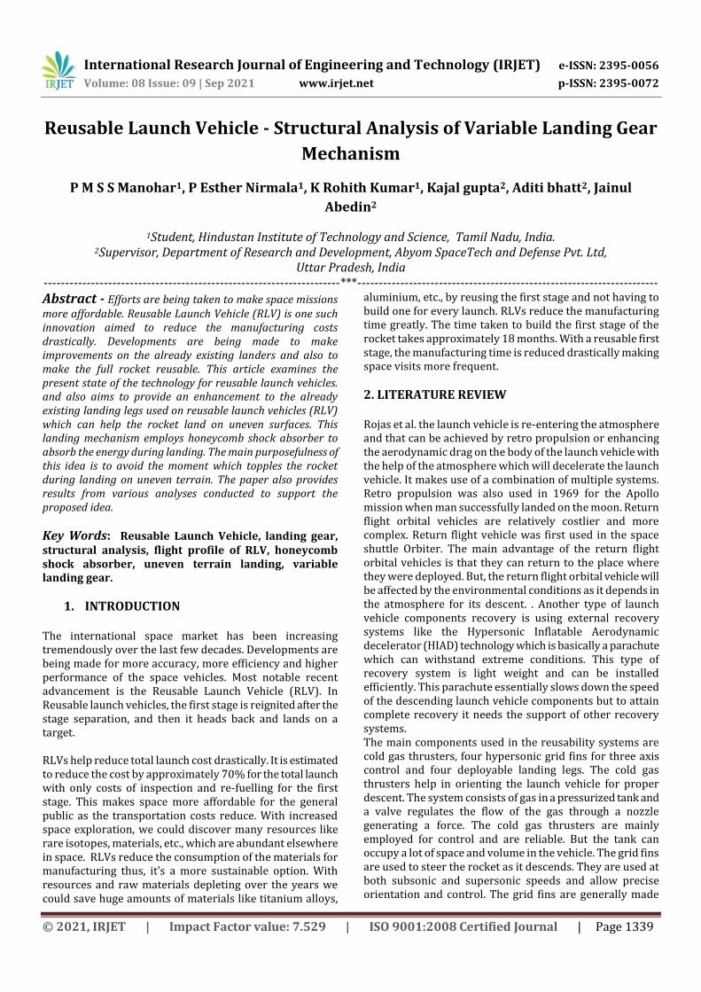
Landing burn: This stage starts a few seconds before the landing takes place. The engine reignites for the last time to bring the rocket to certain velocity and then halt. The four retractable landing gears which are symmetrically attached to the rocket will deploy.
Landing and Recovery: The first stage will be landed on a target or drone ship and will be recovered. There are a number of processes to be done before performing its next launch. The booster will be cleaned and a certain number of tests will be done as it underwent very large aerodynamic and thermal loads. [6]
Fig 1: Flight Profile
4. Components of the landing gear
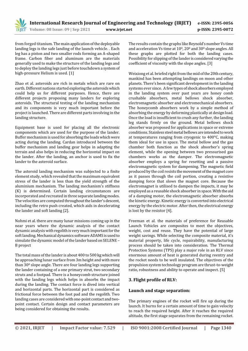
Primary Strut: The secondary struts connect the primary strut to the rocket body. Each landing leg comprises of two secondary struts. The secondary struts take up the axial loads. It is hollow with a thickness of 5mm and length 246mm. Its outer diameter is 45mm and inner diameter is 40mm.AL - 6061 is used for struts which are aerospace grade materials. [7]
Fig 2: Flight Profile
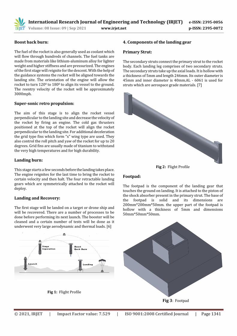
Footpad: The footpad is the component of the landing gear that touches the ground on landing. It is attached to the piston of the shock absorber present in the primary strut. The base of the footpad is solid and its dimensions are 200mm*200mm*50mm. the upper part of the footpad is hollow with a thickness of 5mm and dimensions 50mm*50mm*50mm.
Fig 3: Footpad
International Research Journal of Engineering and Technology (IRJET) e-ISSN: 2395-0056
Volume: 08 Issue: 09 | Sep 2021 www.irjet.net p-ISSN: 2395-0072
© 2021, IRJET | Impact Factor value: 7.529 | ISO 9001:2008 Certified Journal | Page 1342
Shock Absorber Made of Honeycomb:
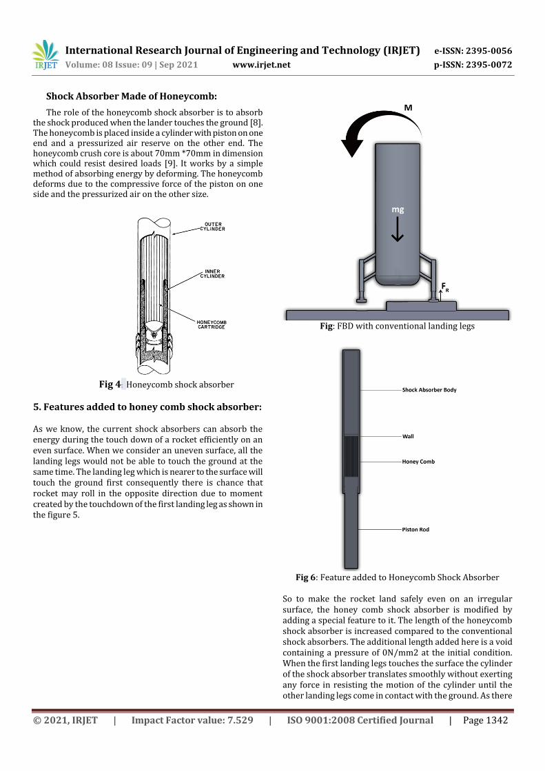
The role of the honeycomb shock absorber is to absorb the shock produced when the lander touches the ground [8]. The honeycomb is placed inside a cylinder with piston on one end and a pressurized air reserve on the other end. The honeycomb crush core is about 70mm *70mm in dimension which could resist desired loads [9]. It works by a simple method of absorbing energy by deforming. The honeycomb deforms due to the compressive force of the piston on one side and the pressurized air on the other size.
Fig 4: Honeycomb shock absorber
5. Features added to honey comb shock absorber: As we know, the current shock absorbers can absorb the energy during the touch down of a rocket efficiently on an even surface. When we consider an uneven surface, all the landing legs would not be able to touch the ground at the same time. The landing leg which is nearer to the surface will touch the ground first consequently there is chance that rocket may roll in the opposite direction due to moment created by the touchdown of the first landing leg as shown in the figure 5.
Fig: FBD with conventional landing legs
Fig 6: Feature added to Honeycomb Shock Absorber
So to make the rocket land safely even on an irregular surface, the honey comb shock absorber is modified by adding a special feature to it. The length of the honeycomb shock absorber is increased compared to the conventional shock absorbers. The additional length added here is a void containing a pressure of 0N/mm2 at the initial condition. When the first landing legs touches the surface the cylinder of the shock absorber translates smoothly without exerting any force in resisting the motion of the cylinder until the other landing legs come in contact with the ground. As there
International Research Journal of Engineering and Technology (IRJET) e-ISSN: 2395-0056
Volume: 08 Issue: 09 | Sep 2021 www.irjet.net p-ISSN: 2395-0072
© 2021, IRJET | Impact Factor value: 7.529 | ISO 9001:2008 Certified Journal | Page 1343
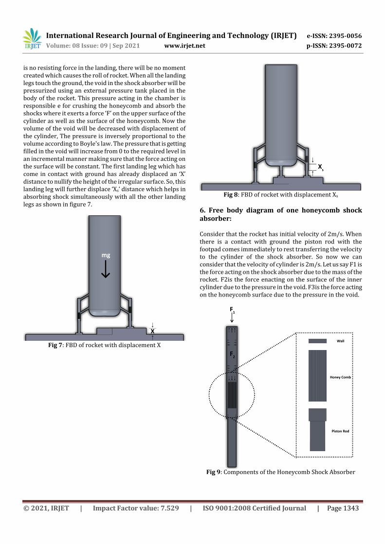
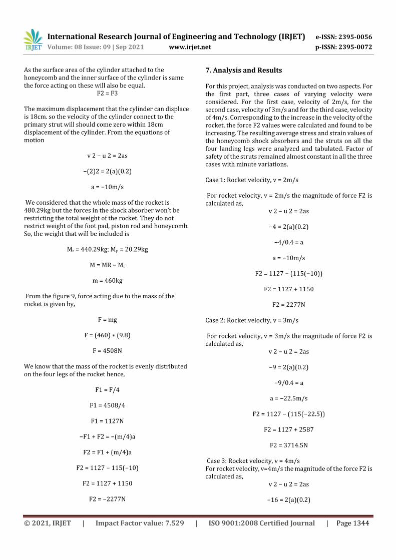
is no resisting force in the landing, there will be no moment created which causes the roll of rocket. When all the landing legs touch the ground, the void in the shock absorber will be pressurized using an external pressure tank placed in the body of the rocket. This pressure acting in the chamber is responsible e for crushing the honeycomb and absorb the shocks where it exerts a force ‘F’ on the upper surface of the cylinder as well as the surface of the honeycomb. Now the volume of the void will be decreased with displacement of the cylinder, The pressure is inversely proportional to the volume according to Boyle's law. The pressure that is getting filled in the void will increase from 0 to the required level in an incremental manner making sure that the force acting on the surface will be constant. The first landing leg which has come in contact with ground has already displaced an ‘X’ distance to nullify the height of the irregular surface. So, this landing leg will further displace ‘Xs’ distance which helps in absorbing shock simultaneously with all the other landing legs as shown in figure 7.
Fig 7: FBD of rocket with displacement X
Fig 8: FBD of rocket with displacement Xs
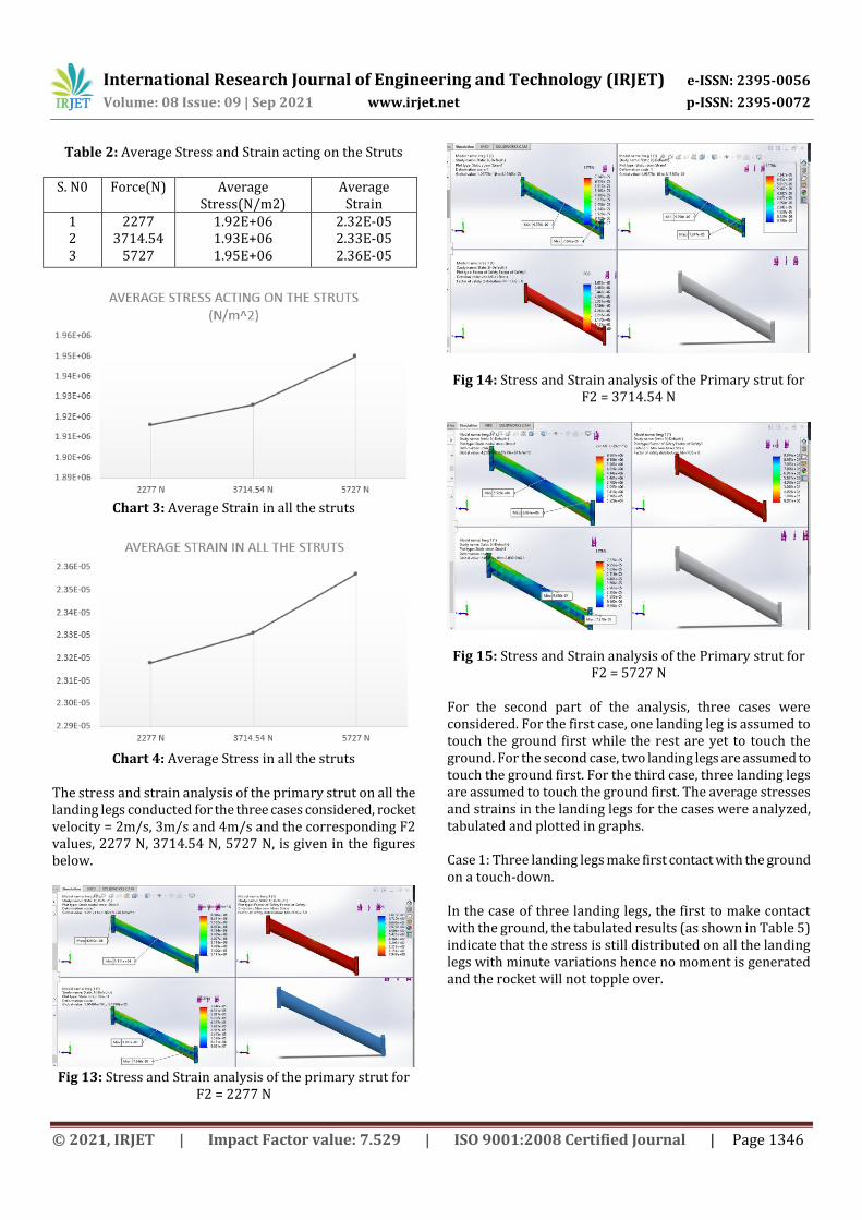
6. Free body diagram of one honeycomb shock absorber: Consider that the rocket has initial velocity of 2m/s. When there is a contact with ground the piston rod with the footpad comes immediately to rest transferring the velocity to the cylinder of the shock absorber. So now we can consider that the velocity of cylinder is 2m/s. Let us say F1 is the force acting on the shock absorber due to the mass of the rocket. F2is the force enacting on the surface of the inner cylinder due to the pressure in the void. F3is the force acting on the honeycomb surface due to the pressure in the void.
Fig 9: Components of the Honeycomb Shock Absorber
International Research Journal of Engineering and Technology (IRJET) e-ISSN: 2395-0056
Volume: 08 Issue: 09 | Sep 2021 www.irjet.net p-ISSN: 2395-0072
© 2021, IRJET | Impact Factor value: 7.529 | ISO 9001:2008 Certified Journal | Page 1344
As the surface area of the cylinder attached to the honeycomb and the inner surface of the cylinder is same the force acting on these will also be equal.
F2 = F3
The maximum displacement that the cylinder can displace is 18cm. so the velocity of the cylinder connect to the primary strut will should come zero within 18cm displacement of the cylinder. From the equations of motion
v 2 − u 2 = 2as
−(2)2 = 2(a)(0.2)
a = −10m/s We considered that the whole mass of the rocket is 480.29kg but the forces in the shock absorber won’t be restricting the total weight of the rocket. They do not restrict weight of the foot pad, piston rod and honeycomb. So, the weight that will be included is
Mr = 440.29kg; Mp = 20.29kg
M = MR − Mr
m = 460kg
From the figure 9, force acting due to the mass of the rocket is given by,
F = mg
F = (460) ∗ (9.8)
F = 4508N
We know that the mass of the rocket is evenly distributed on the four legs of the rocket hence,
F1 = F/4
F1 = 4508/4
F1 = 1127N
−F1 + F2 = −(m/4)a
F2 = F1 + (m/4)a
F2 = 1127 − 115(−10)
F2 = 1127 + 1150
F2 = −2277N
7. Analysis and Results For this project, analysis was conducted on two aspects. For the first part, three cases of varying velocity were considered. For the first case, velocity of 2m/s, for the second case, velocity of 3m/s and for the third case, velocity of 4m/s. Corresponding to the increase in the velocity of the rocket, the force F2 values were calculated and found to be increasing. The resulting average stress and strain values of the honeycomb shock absorbers and the struts on all the four landing legs were analyzed and tabulated. Factor of safety of the struts remained almost constant in all the three cases with minute variations. Case 1: Rocket velocity, v = 2m/s For rocket velocity, v = 2m/s the magnitude of force F2 is calculated as,
v 2 − u 2 = 2as
−4 = 2(a)(0.2)
−4/0.4 = a
a = −10m/s
F2 = 1127 − (115(−10))
F2 = 1127 + 1150
F2 = 2277N Case 2: Rocket velocity, v = 3m/s For rocket velocity, v = 3m/s the magnitude of force F2 is calculated as,
v 2 − u 2 = 2as
−9 = 2(a)(0.2)
−9/0.4 = a
a = −22.5m/s
F2 = 1127 − (115(−22.5))
F2 = 1127 + 2587
F2 = 3714.5N Case 3: Rocket velocity, v = 4m/s For rocket velocity, v=4m/s the magnitude of the force F2 is calculated as,
v 2 − u 2 = 2as
−16 = 2(a)(0.2)

International Research Journal of Engineering and Technology (IRJET) e-ISSN: 2395-0056
Volume: 08 Issue: 09 | Sep 2021 www.irjet.net p-ISSN: 2395-0072
© 2021, IRJET | Impact Factor value: 7.529 | ISO 9001:2008 Certified Journal | Page 1345
a = −40m/s
F2 = 1127 − (115(−40))
F2 = 1127 + 4600
F2 = 5727N
From the tabulated results graphs were plotted. From these graphs as shown in Figure 4 and Figure 5, it is found that the stress and strain on the honeycomb shock absorber increased with 1m/s increase in the velocity. The stress on the honeycomb shock absorbers in all the legs is found to be 7.98E+05 N/m2. The strain in the honeycomb shock absorbers is found to be 9.69E-06. The stress and strain analysis of the honeycomb shock absorber in all the landing legs for the three cases, velocity = 2m/s, 3m/s and 4m/s and the corresponding F2 values is given in the figures below. Table 1: Average Stress and Strain acting on the Honeycomb S. N0 Force(N) Average
Stress(N/m2) Average
Strain 1 2 3
2277 3714.54
5727
6.64E+05 7.98E+05 9.97E+05
8.10E-06 9.69E-06 1.21E-05
Chart 1: Average stress in all the Honeycombs
Chart 2: Average Strain in all the Honeycombs
Fig 10: Stress and Strain analysis of the Honeycomb for F2
= 2277 N
Fig 11: Stress and Strain analysis of the Honeycomb for F2
= 3714.54 N
Fig 12: Stress and Strain analysis of the Honeycomb for F2
= 5727 N
The graphs plotted from the tabulated results indicate increase in stress and strain in all the struts on the four landing legs with 1m/s increase in the velocity. The stress acting on the struts is found to be 1.93E+06 and the strain is found to be 2.33E-05.
International Research Journal of Engineering and Technology (IRJET) e-ISSN: 2395-0056
Volume: 08 Issue: 09 | Sep 2021 www.irjet.net p-ISSN: 2395-0072
© 2021, IRJET | Impact Factor value: 7.529 | ISO 9001:2008 Certified Journal | Page 1346
Table 2: Average Stress and Strain acting on the Struts S. N0 Force(N) Average
Stress(N/m2) Average
Strain 1 2 3
2277 3714.54
5727
1.92E+06 1.93E+06 1.95E+06
2.32E-05 2.33E-05 2.36E-05
Chart 3: Average Strain in all the struts
Chart 4: Average Stress in all the struts
The stress and strain analysis of the primary strut on all the landing legs conducted for the three cases considered, rocket velocity = 2m/s, 3m/s and 4m/s and the corresponding F2 values, 2277 N, 3714.54 N, 5727 N, is given in the figures below.
Fig 13: Stress and Strain analysis of the primary strut for
F2 = 2277 N
Fig 14: Stress and Strain analysis of the Primary strut for F2 = 3714.54 N
Fig 15: Stress and Strain analysis of the Primary strut for F2 = 5727 N
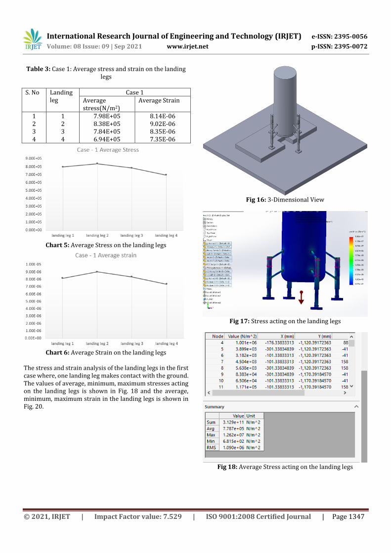
For the second part of the analysis, three cases were considered. For the first case, one landing leg is assumed to touch the ground first while the rest are yet to touch the ground. For the second case, two landing legs are assumed to touch the ground first. For the third case, three landing legs are assumed to touch the ground first. The average stresses and strains in the landing legs for the cases were analyzed, tabulated and plotted in graphs. Case 1: Three landing legs make first contact with the ground on a touch-down. In the case of three landing legs, the first to make contact with the ground, the tabulated results (as shown in Table 5) indicate that the stress is still distributed on all the landing legs with minute variations hence no moment is generated and the rocket will not topple over.
International Research Journal of Engineering and Technology (IRJET) e-ISSN: 2395-0056
Volume: 08 Issue: 09 | Sep 2021 www.irjet.net p-ISSN: 2395-0072
© 2021, IRJET | Impact Factor value: 7.529 | ISO 9001:2008 Certified Journal | Page 1347
Table 3: Case 1: Average stress and strain on the landing legs
S. No Landing
leg Case 1
Average stress(N/m2)
Average Strain
1 2 3 4
1 2 3 4
7.98E+05 8.38E+05 7.84E+05 6.94E+05
8.14E-06 9.02E-06 8.35E-06 7.35E-06
Chart 5: Average Stress on the landing legs
Chart 6: Average Strain on the landing legs
The stress and strain analysis of the landing legs in the first case where, one landing leg makes contact with the ground. The values of average, minimum, maximum stresses acting on the landing legs is shown in Fig. 18 and the average, minimum, maximum strain in the landing legs is shown in Fig. 20.
Fig 16: 3-Dimensional View
Fig 17: Stress acting on the landing legs
Fig 18: Average Stress acting on the landing legs
International Research Journal of Engineering and Technology (IRJET) e-ISSN: 2395-0056
Volume: 08 Issue: 09 | Sep 2021 www.irjet.net p-ISSN: 2395-0072
© 2021, IRJET | Impact Factor value: 7.529 | ISO 9001:2008 Certified Journal | Page 1348
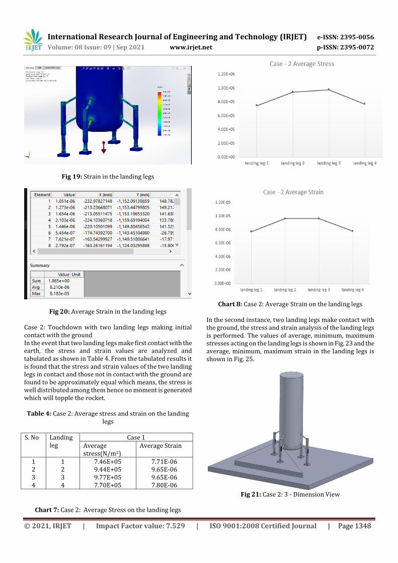
Fig 19: Strain in the landing legs
Fig 20: Average Strain in the landing legs Case 2: Touchdown with two landing legs making initial contact with the ground In the event that two landing legs make first contact with the earth, the stress and strain values are analyzed and tabulated as shown in Table 4. From the tabulated results it is found that the stress and strain values of the two landing legs in contact and those not in contact with the ground are found to be approximately equal which means, the stress is well distributed among them hence no moment is generated which will topple the rocket. Table 4: Case 2: Average stress and strain on the landing
legs S. No Landing
leg Case 1
Average stress(N/m2)
Average Strain
1 2 3 4
1 2 3 4
7.46E+05 9.44E+05 9.77E+05 7.70E+05
7.71E-06 9.65E-06 9.65E-06 7.80E-06
Chart 7: Case 2: Average Stress on the landing legs
Chart 8: Case 2: Average Strain on the landing legs
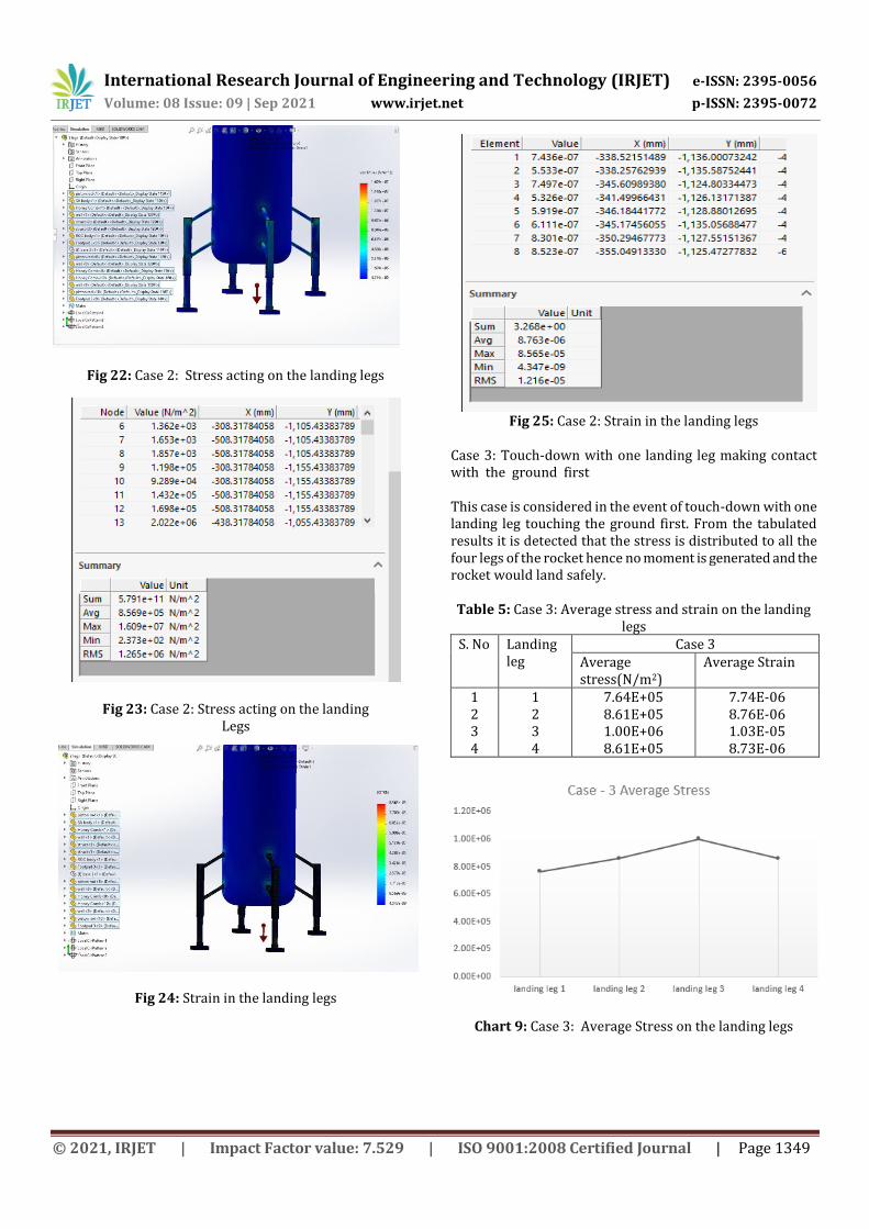
In the second instance, two landing legs make contact with the ground, the stress and strain analysis of the landing legs is performed. The values of average, minimum, maximum stresses acting on the landing legs is shown in Fig. 23 and the average, minimum, maximum strain in the landing legs is shown in Fig. 25.
Fig 21: Case 2: 3 - Dimension View
International Research Journal of Engineering and Technology (IRJET) e-ISSN: 2395-0056
Volume: 08 Issue: 09 | Sep 2021 www.irjet.net p-ISSN: 2395-0072
© 2021, IRJET | Impact Factor value: 7.529 | ISO 9001:2008 Certified Journal | Page 1349
Fig 22: Case 2: Stress acting on the landing legs
Fig 23: Case 2: Stress acting on the landing
Legs
Fig 24: Strain in the landing legs
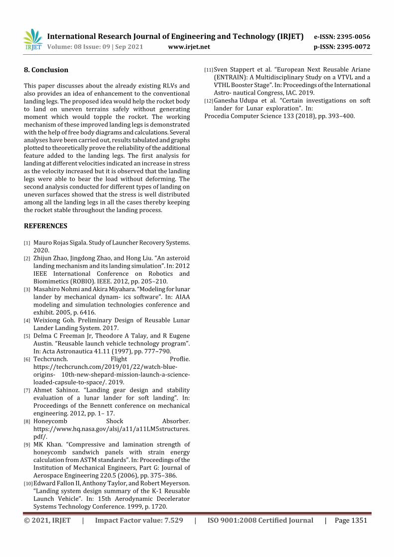
Fig 25: Case 2: Strain in the landing legs Case 3: Touch-down with one landing leg making contact with the ground first This case is considered in the event of touch-down with one landing leg touching the ground first. From the tabulated results it is detected that the stress is distributed to all the four legs of the rocket hence no moment is generated and the rocket would land safely. Table 5: Case 3: Average stress and strain on the landing
legs S. No Landing
leg Case 3
Average stress(N/m2)
Average Strain
1 2 3 4
1 2 3 4
7.64E+05 8.61E+05 1.00E+06 8.61E+05
7.74E-06 8.76E-06 1.03E-05 8.73E-06
Chart 9: Case 3: Average Stress on the landing legs

International Research Journal of Engineering and Technology (IRJET) e-ISSN: 2395-0056
Volume: 08 Issue: 09 | Sep 2021 www.irjet.net p-ISSN: 2395-0072
© 2021, IRJET | Impact Factor value: 7.529 | ISO 9001:2008 Certified Journal | Page 1350
Chart 10: Case 3: Average Strain on the landing legs In the third instance, three landing legs make contact with the ground, the stress and strain analysis of the landing legs is performed. The values of average, minimum, maximum stresses acting on the landing legs is shown in Fig. 28 and the average, minimum, maximum strain in the landing legs is shown in Fig. 30.
Fig 26: Case 3: 3-Dimension View
Fig 27: Case 3: Stress acting on the landing legs
Fig 28: Case 3: Stress acting on the landing Legs
Fig 29: Case 3: Strain in the landing legs
Fig 30: Case 3: Strain in the landing legs
International Research Journal of Engineering and Technology (IRJET) e-ISSN: 2395-0056
Volume: 08 Issue: 09 | Sep 2021 www.irjet.net p-ISSN: 2395-0072
© 2021, IRJET | Impact Factor value: 7.529 | ISO 9001:2008 Certified Journal | Page 1351
8. Conclusion This paper discusses about the already existing RLVs and also provides an idea of enhancement to the conventional landing legs. The proposed idea would help the rocket body to land on uneven terrains safely without generating moment which would topple the rocket. The working mechanism of these improved landing legs is demonstrated with the help of free body diagrams and calculations. Several analyses have been carried out, results tabulated and graphs plotted to theoretically prove the reliability of the additional feature added to the landing legs. The first analysis for landing at different velocities indicated an increase in stress as the velocity increased but it is observed that the landing legs were able to bear the load without deforming. The second analysis conducted for different types of landing on uneven surfaces showed that the stress is well distributed among all the landing legs in all the cases thereby keeping the rocket stable throughout the landing process.
REFERENCES [1] Mauro Rojas Sigala. Study of Launcher Recovery Systems.
2020. [2] Zhijun Zhao, Jingdong Zhao, and Hong Liu. “An asteroid
landing mechanism and its landing simulation”. In: 2012 IEEE International Conference on Robotics and Biomimetics (ROBIO). IEEE. 2012, pp. 205–210.
[3] Masahiro Nohmi and Akira Miyahara. “Modeling for lunar lander by mechanical dynam- ics software”. In: AIAA modeling and simulation technologies conference and exhibit. 2005, p. 6416.
[4] Weixiong Goh. Preliminary Design of Reusable Lunar Lander Landing System. 2017.
[5] Delma C Freeman Jr, Theodore A Talay, and R Eugene Austin. “Reusable launch vehicle technology program”. In: Acta Astronautica 41.11 (1997), pp. 777–790.
[6] Techcrunch. Flight Proflie. https://techcrunch.com/2019/01/22/watch-blue-origins- 10th-new-shepard-mission-launch-a-science-loaded-capsule-to-space/. 2019.
[7] Ahmet Sahinoz. “Landing gear design and stability evaluation of a lunar lander for soft landing”. In: Proceedings of the Bennett conference on mechanical engineering. 2012, pp. 1– 17.
[8] Honeycomb Shock Absorber. https://www.hq.nasa.gov/alsj/a11/a11LM5structures. pdf/.
[9] MK Khan. “Compressive and lamination strength of honeycomb sandwich panels with strain energy calculation from ASTM standards”. In: Proceedings of the Institution of Mechanical Engineers, Part G: Journal of Aerospace Engineering 220.5 (2006), pp. 375–386.
[10] Edward Fallon II, Anthony Taylor, and Robert Meyerson. “Landing system design summary of the K-1 Reusable Launch Vehicle”. In: 15th Aerodynamic Decelerator Systems Technology Conference. 1999, p. 1720.
[11] Sven Stappert et al. “European Next Reusable Ariane (ENTRAIN): A Multidisciplinary Study on a VTVL and a VTHL Booster Stage”. In: Proceedings of the International Astro- nautical Congress, IAC. 2019.
[12] Ganesha Udupa et al. “Certain investigations on soft lander for Lunar exploration”. In:
Procedia Computer Science 133 (2018), pp. 393–400.