The technology described in this article “Automatic EQ, rossover … · Chavez M, Ramos G...
15
Chavez M, Ramos G Automatic EQ, Crossover and Alignment of Speaker Systems 1 Presented at the ALMA Winter Symposium 2011 January 4-5 th Las Vegas NV Chavez Miguel (miguel (dot) [email protected] ), Ramos German Automatic EQ, Crossover and Alignment of Speaker Systems In the last decade, loudspeaker technology has continued to evolve at an ever increasing rhythm. Improvements have come from new materials, new manufacturing methods, better measurement equipment, improved non-linear modeling tools, to more accurate uses of finite element analysis tools. It is almost unimaginable to think of a loudspeaker design cycles being done without the use of new technology. It should come as no surprise that the use of DSP and their tools are now, more than ever, helping loudspeaker and system designers, becoming widely spread and critical within the loudspeakers industry. With this, it now makes sense for loudspeaker manufacturers to think forward with new DSP techniques and use cases as a new variable in the design process. Shorter product timelines and constant markets shifts require more efficient design techniques than ever before. Analog Devices has designed software for improving such system design within their DSP lines of products (i.e. SigmaDSP and Sharc). The Auto EQ for SigmaStudio is intended to reduce design time by allowing designers to focus on other important system considerations. The technology described in this article “Automatic EQ, Crossover and Alignment of Speakers Systems” was developed to automate a common repetitive task in audio speaker and system design, to equalize and tune audio systems to a desired electro-acoustical target response. SigmaStudio - a user friendly, intuitive and expandable graphical programming environment for Audio/DSP applications. To better understand the platform in which the Auto-EQ Plug-Inn was developed, this article briefly describes the environment for which it was designed “SigmaStudio“. Graphical development environments have been used in the audio industry for a number of years. Those who have fewer limitations have persisted and found a well establish pool of users reluctant to modify their design patterns and adopt different embedded processors and design environments. SigmaStudio is a development environment originally designed for the SigmaDSP family of audio specific signal processors. SigmaStudio along with
Transcript of The technology described in this article “Automatic EQ, rossover … · Chavez M, Ramos G...

Chavez M, Ramos G Automatic EQ, Crossover and Alignment of Speaker Systems
1
Presented at the ALMA Winter Symposium
2011 January 4-5th Las Vegas NV
Chavez Miguel (miguel (dot) [email protected]), Ramos German
Automatic EQ, Crossover and Alignment of Speaker Systems
In the last decade, loudspeaker technology has continued to evolve at an ever increasing rhythm. Improvements have come from new materials, new manufacturing methods, better measurement equipment, improved non-linear modeling tools, to more accurate uses of finite element analysis tools. It is almost unimaginable to think of a loudspeaker design cycles being done without the use of new technology. It should come as no surprise that the use of DSP and their tools are now, more than ever, helping loudspeaker and system designers, becoming widely spread and critical within the loudspeakers industry. With this, it now makes sense for loudspeaker manufacturers to think forward with new DSP techniques and use cases as a new variable in the design process.
Shorter product timelines and constant markets shifts require more efficient design techniques than ever before. Analog Devices has designed software for improving such system design within their DSP lines of products (i.e. SigmaDSP and Sharc). The Auto EQ for SigmaStudio is intended to reduce design time by allowing designers to focus on other important system considerations.
The technology described in this article “Automatic EQ, Crossover and Alignment of Speakers Systems” was developed to automate a common repetitive task in audio speaker and system design, to equalize and tune audio systems to a desired electro-acoustical target response.
SigmaStudio - a user friendly, intuitive and expandable graphical programming environment for Audio/DSP applications.
To better understand the platform in which the Auto-EQ Plug-Inn was developed, this article briefly describes the environment for which it was designed “SigmaStudio“.
Graphical development environments have been used in the audio industry for a number of years. Those who have fewer limitations have persisted and found a well establish pool of users reluctant to modify their design patterns and adopt different embedded processors and design environments. SigmaStudio is a development environment originally designed for the SigmaDSP family of audio specific signal processors. SigmaStudio along with

Chavez M, Ramos G Automatic EQ, Crossover and Alignment of Speaker Systems
2
the SigmaDSP family of digital signal processors were designed for simplifying design considerations within the audio market allowing for decreased time-to-market, by bringing closer analog audio engineers to the DSP design methodologies and intricacies.
SigmaStudio (1.0) was originally created as a stand along GUI (graphical user interface) application to control the parameters of a predetermined audio signal flow. It allowed the control of a set of derived values that can manage (among other algorithms): dynamic processors, filters, proprietary specialization effects and other pre-written ROM based algorithms. At the time, users had no immediate access to the DSP’s audio flow. The result was that, even when the DSP was a fully programmable audio solution, the end user was not directly exposed to (and in many cases aware of) such programmability. At the same time as SigmaStudio 1.0, other set of tools became available. Such tools allowed modifying the audio signal flow within the SigmaDSP and were the signal flow design complement for SigmaStudio 1.0. User needs demanded an integrated solution that would allow a real time control of parameters as well as a signal flow design tool (refer to ADAU1953).
Early adopters started using the tool by making the switch between analog to an all-digital media signal path. The switch to digital signal processors also enabled to lower the logistics and technology involved in designing analog modules, unifying PCB designs, and hence decreasing the costs, this being particularly true with the integration of ADCs and DACs in the same die as the DSP.
The second generation of SigmaStudio allows full control and creation of generic signal flows. Among its features, SigmaStudio enables:
the creation of an intuitive design and user interface among audio design engineers,
the creation of optimized code by allowing memory reusability among modules,
the use of object oriented design techniques to optimize runtime modules,
object modularity among algorithm designers,
real-time tuning capabilities and A-B fast switching,
to show a simulated transfer function for frequency domain representation of time domain signal processing, including loudspeaker’s frequency and phase response,
to hide and protects intellectual property,
individual and independent distribution of algorithms and other IP,
runtime debug of points within a schematic audio flows including data visualization,
multi-core, multi-DSP signal flow creation,
ease of system integration by creating all necessary support files that can be embedded in the final microprocessor (automatic C code and header files generation),
the use of time domain simulation,
the embedding of assembly code for coding of customer proprietary IP within a graphical control GUI, allowing a mix of proprietary IP and newly customize, proprietary algorithms,
the design complex audio flows in minutes
Chavez M, Ramos G Automatic EQ, Crossover and Alignment of Speaker Systems
3
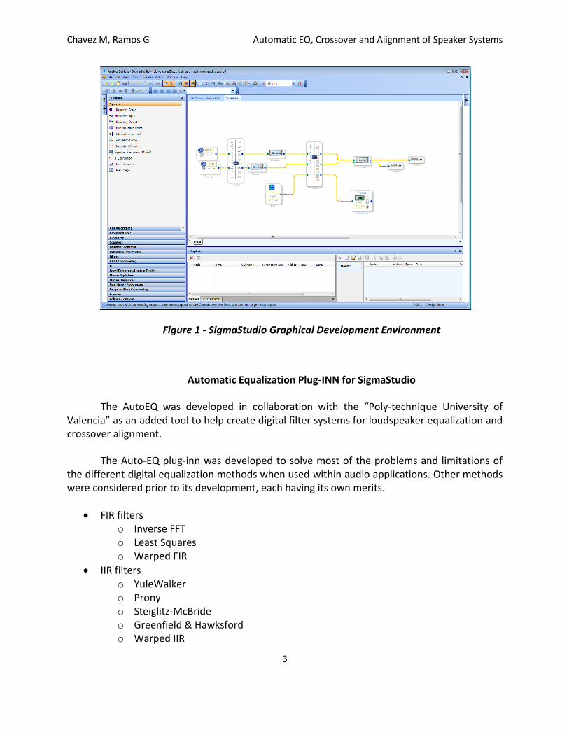
Figure 1 - SigmaStudio Graphical Development Environment
Automatic Equalization Plug-INN for SigmaStudio
The AutoEQ was developed in collaboration with the “Poly-technique University of Valencia” as an added tool to help create digital filter systems for loudspeaker equalization and crossover alignment.
The Auto-EQ plug-inn was developed to solve most of the problems and limitations of the different digital equalization methods when used within audio applications. Other methods were considered prior to its development, each having its own merits.
FIR filters o Inverse FFT o Least Squares o Warped FIR
IIR filters o YuleWalker o Prony o Steiglitz-McBride o Greenfield & Hawksford o Warped IIR

Chavez M, Ramos G Automatic EQ, Crossover and Alignment of Speaker Systems
4
Considerations taken for developing the algorithm include:
working within a logarithmic domain (frequency and magnitude) that better resembles human perception,
ability to include user defined constraints,
flexibility to perform subjective changes and modifications after the design without the need to redesign,
low implementation cost,
low system latency,
filter design scalability.
A challenge during the design of the Auto EQ was to include constraints on the filter design process due to: numerical concerns for internal DSP implementations, and EQ concerns when trying to compensate for excessive gain variations and low and high frequencies boosts. Allowing the design of low frequencies and high gain could potentially damage both, power dissipation when compensating for then natural speaker roll off at low frequencies and the loudspeaker coil, surround, spider and other electro-mechanical elements when reaching their mechanical limits.
A second challenge when dealing with digital filters is to limit group delay and system latency. Excessive gain and slope at high frequencies may also create ringing. Similarly, also when using IIR filters the proximity of the poles to the unit circle (Q) must also be limited to avoid quantization errors and the design of potentially unstable filters with noticeable and unpleasant ringing.
Some of the methods previously mentioned, in particularly FIR filters, could introduce excessive delay when linear phase is required. Excessive delay is prohibited in some applications such as live sound reinforcement. In the case of IIR filters, designs require non factorized numerator of order N and a denominator of order M. The final DSP implementation is then done in second order sections (SOS). It is also desirable that the SOS chain be ordered in perceptual importance. Initially generated filters will be those where equalization is most needed and the following filter will equalize less critical corrections; this is the scalability property of the system.
The primary objective for a digital equalizer Hequ() is to modify the response of the
loudspeaker Hlspk() to match a desired electro-acoustical target response Htarget(). To
accomplish this, the complex response of the filter Hequ() is:

Chavez M, Ramos G Automatic EQ, Crossover and Alignment of Speaker Systems
5
Figure 2 –Representation of digital, analog and acoustic audio loudspeaker system.
The design includes the proper time windowing of the impulse response to avoid or reduce to a desirable level the influence of the measurement room Hroom( ). The response of
the equalizer Hequ() must be approximated when Hlspk()·Hroom() is a non-minimum phase systems.
In order to avoid the creation of continuously overlapping SOS sections, it is recommended that the target response respects the natural band-pass
characteristic of each element within a loudspeaker. It is also possible to extend the band always attempting to avoid the introduction of excessive gain in the equalization that may cause both digital and electro-mechanical artifacts. The target response will be defined as a numeric vector that gets stored in memory and used for the iterative process.
The Hlspk() could be constructed from a weighted mean of several measurements at different positions in order to widen the effective area of equalization.
Second order sections implemented as a sequence of IIR filters were selected to be designed iteratively as shown in Figure 3.
Figure 3 – Cascaded Second Order Sections
Audio In Audio Out
Amplifier
Loudspeaker
Equalizer
SOS 1
Audio In
SOS 2
SOS 3 SOS N Audio Out
H1(z) H2(z) H3(z) HN(z)
Hequ(z) = H1(z) H2(z) H3(z)… HN(z)

Chavez M, Ramos G Automatic EQ, Crossover and Alignment of Speaker Systems
6
Each SOS is designed as a high-pass, low-pass, parametric or shelving filter defined by its parameters (Frequency, Gain and Q) that could be either fixed, initialized by the user, or automatically assigned as a generic parametric filter. The parametric approach used allows for the inclusion of constraints in the design by limiting the frequency range to perform the equalization including the maximum and minimum allowed gain and Q. This iterative process searches for sets of parameters (frequency, Q and Gain) for each section as opposed to specific filter coefficients, making the design parametric. The design is also more intuitive to acoustical engineers and provides a more common understanding rather than purely mathematical.
To enable a psychoacoustic search, filters are designed employing a cost function e1 that takes into account the following considerations:
The error is evaluated over a discrete frequency axis logarithmically spaced with a configurable resolution of fractions of octave.
The error is evaluated in decibels in norm-1 (area)
The expression of the cost function e1 is:
that represents the mean absolute error in decibels between the target response and the equalized loudspeaker, evaluated over a logarithmic frequency axis. The vector W(freqrk) is an optional weighting vector that prevents equalization in a predefined frequency band (i.e. due to a cancellation in the measurement) or allows for emphasizing in others.
The initial step is the search for filters. Filters are assigned using a search method that allows setting of initial parameters of the SOS on error area criteria. The biggest difference (error area) is equalized with a peak filter by default. The initial criteria of a peaking filter H1(w) is selected as follows:
The central frequency f1 will be the geometric mean between the zero-crossing points of the area,
The gain dB1 will be the value of the error at f1,
The Q could be defined searching for the -3dB point (if present), or fixed initially between a value from 1.5 to 3 allowing for following optimization step to adjust it.
The second step is the optimization of the initial values for parameters obtained with the direct search method. A heuristic approach was used for this step. Since the initial values are good and only three parameters are to be optimized, a randomization of the values is used. If the new random filter is a better fit then these new values become values for the following

Chavez M, Ramos G Automatic EQ, Crossover and Alignment of Speaker Systems
7
iteration. This process is repeated and ends after a number of times or when a filter has not improved after a number of times.
Once the SOS parameters have been optimized the process is repeated for a new second order section that starts with both the loudspeaker measurement and the previously assigned filters. The design of SOS sections together with the error area criteria, allows for obtaining scalable filters making the initial filters the most critical for the correction of a frequency band within the target constraints. Having filters sorted in order of importance allows for a comparison of perceptual filter response and characteristics as well as for further optimization when DSP resources become scarce.
AutoEQ implementation in SigmaStudio
The AutoEQ plug inn, in its current state was designed to simply the design cycles specifically for powered loudspeakers although other markets are being considered for its use. In its current state it can equalize single, two and three way speakers. Simplicity and intuitive design have been carefully taken into account whereas most common buttons and switches have been exposed immediately to the users and other less common parameters are contained in control with less immediate access. For simplicity, the design has been designed with tabs representing different functions within the design cycle in natural order. For multi-way systems, those functions are: Source Response, Crossover, Target Response, Filters and Crossover Alignment.
The following displays the content of the consecutive tabs with an explanation of its behavior and use:

Chavez M, Ramos G Automatic EQ, Crossover and Alignment of Speaker Systems
8
Source Response Tab
The Source Response Tab allows for importing impulse responses measured with a variety of measurement systems as well as for directly importing a frequency response if information has been stored in the frequency domain. A half cosine window is created to allow for windowing the impulse response when significant reflections or room nodes are evident from the measurements. The time domain window is user modifiable by dragging its end points or changing the knob.
Once changes are done either in the time domain impulse response or the window, an updated frequency representation of the response is shown to the user. Once in the frequency domain, octave smoothing is also allowed to prevent the effects caused by either the measurement and/or the windowing making it a better fit to human hearing perception. A gain offset allows for gain corrections that may happen between different speaker components.
Figure 4 – Source Response Tab

Chavez M, Ramos G Automatic EQ, Crossover and Alignment of Speaker Systems
9
Target Response
The Target Response tab serves many functions including:
1. Manually assigning a target response using the pencil tool 2. Assigning a target response using common filters 3. Assigning a different weight to increase the relative importance of certain bands and or
lack of importance of others. Users can use this feature to lessen the algorithm attention to bands where it is know that speaker tolerances are wide or when the measurement presents a signature that is much less perceptible than others (i.e. a sudden dip is less perceptible than a peak of similar magnitude).
4. Modifying the overall component measurement gain.
All target curve design constraints excluding the Crossover position are set in this tab; users are expected to spend a good amount of time in this tab clearly constraining their system within their known component physical limits.
Figure 5 – Target Response Tab

Chavez M, Ramos G Automatic EQ, Crossover and Alignment of Speaker Systems
10
Design Settings
The primary use of the Design Settings tab is to initialize filters as well as triggering a Design. As shown in Figure 6, it is also possible to fine-tune the design parameters to accommodate for user defined constraints different from the default.
The user is allowed to initialize the type of filters used as shown in Figure 7. It is recommended that the first filter used be high pass to prevent using many peaking filters from attempting to extend the low frequencies of a transducer.
It is in the Design Tab that the user can modify the amount of filters used for the equalization process (refer to the Current Design section within the TAB) depending on the user digital filter budget.
Figure 6 – Design Settings Tab

Chavez M, Ramos G Automatic EQ, Crossover and Alignment of Speaker Systems
11
Figure 7 – Initializing Filters

Chavez M, Ramos G Automatic EQ, Crossover and Alignment of Speaker Systems
12
Filters TAB
This tab is used to see the result of the filter assignation previous to aligning the system crossover (if applicable). Users are able to see the effect of the various filters being assigned and their unique equalization contribution. It is in this tab were the user can experiment removing filters that least contribute to the equalization of the transducer. To attempt to remove filters, the user must start by the least important filters placed at the end of the filter list. Each filter (row) also contains a way to bypass filters allowing the real time perceptual comparison between having the filter and bypassing them.
Figure 8 – Filters Tab showing system generated filters

Chavez M, Ramos G Automatic EQ, Crossover and Alignment of Speaker Systems
13
Crossover Tab
The Crossover Tab allow for setting the crossover points, as well as the filter that sets the crossover. The user can drag and drop the filter for each component or write specifically the desired frequency. The filter type used can be modified between Linkwitz-Riley with 12, 24, 36 and 48 decibels per octave. When selecting some orders, it must be inverted one of the channels to allow for phase alignment. Selecting the Link Enable button allows for modifying both filters (high-pass and low-pass) simultaneously. Figure 9 shows a specific example for the Crossover Tab.
The selection of the crossover frequencies must be carried out taking into account the following considerations:
Natural frequency response of the transducers
Directivity patterns of the drivers
Power handling of the transducers
Final subjective testing
Figure 9 – Crossover Tab

Chavez M, Ramos G Automatic EQ, Crossover and Alignment of Speaker Systems
14
Crossover Alignment Tab
The last tab allows for the alignment of independent bands when working with multi-way speakers systems. The algorithm finds a delay that gives the least error from the target response achieving proper phase alignment. The user can also manually adjust both the Delay and Gain giving the user further control over the system alignment.
Figure 10 – Crossover Alignment Tab
Conclusion
The algorithm presented here is one of a many used for automatically correcting the equalization of an audio systems. The AutoEQ provides good control over a wide variety of speaker parameters and yields satisfactory constrained results. This plug-inn is a tool that helps the designers. Users still require an understanding of their system for better system tuning and results. Because of the amount of user modifiable parameters, users can easily create non optimum solutions. Further algorithms and usability improvements are yet to be designed and implemented.
Chavez M, Ramos G Automatic EQ, Crossover and Alignment of Speaker Systems
15
Biography
Analog Devices, SigmaStudio ver 3.3, Users Manual
Irrgang T, Simplify Audio Setups with a SigmaDSP Pre-Programmed, Fully Configurable Digital Audio Processor, Analog Dialog 36-01, 2002.
Chavez M, Huin C, “SigmaStudio - A user friendly, intuitive and expandable, graphical development environment for Audio/DSP applications”, Presented at the 120th AES convention, Paris 2006
A. Härma, M. Karjalainen, L. Savioja, V. Välimäki, U. K. Laine, J. Huopaniemi, “Frequency-Warped Signal Processing for Audio Applications”, J. Audio Eng. Soc. vol. 48 no. 11, pp. 1011-1031 (Nov. 2000)
O. Kirkeby, P. A. Nelson, H. Hamada, F. Orduña-Bustamante. “Fast Deconvolution of Multichannel Systems Using Regularization”, ISVR Technical report, University of Southampton, 255 (1996)
B. Friedlander, B. Porat, "The Modified Yule-Walker Method of ARMA Spectral Estimation," IEEE Transactions on Aerospace Electronic Systems, AES-20, no. 2, pp. 158-173 (Mar. 1984)
J. Mourjopoulos, “Digital Equalization Methods for Audio Systems”, presented at the 84th Convention of the Audio Engineering Society, preprint 2598, (Mar. 1988)
K. Steiglitz, L. E. McBride, “A Technique for the Identification of Linear Systems”, IEEE Trans. Autom. Control, vol. AC-10, no. 4, pp. 461-464 (1965)
R. Greenfield, M. Hawksford “Efficient Filter Design for Loudspeaker Equalization”, J. Audio Eng. Soc. vol. 39, no. 10, pp. 739-751 (Oct. 1991)
T. Parks, C. S. Burrus, Digital Filter Design, Ed. Wiley & Sons (1987)


![Chapter 6 - Chromedia · Chapter 6 Equilibrium Chemistry 213 K cd ab = [] [] CD AB eq eq eq eq 6.5 Here we include the subscript “eq” to indicate a concentration at equilib‑](https://static.fdocuments.us/doc/165x107/5f39c80721ac1114a433e66d/chapter-6-chromedia-chapter-6-equilibrium-chemistry-213-k-cd-ab-cd-ab.jpg)