The Phaserunner Motor Controller V2 - ebikes.ca · If you are setting up a system with regenerative...
16
The Phaserunner Motor Controller V2 User Manual – Rev2.0, Connectorized Grin Technologies Ltd Vancouver, BC, Canada ph: (604) 569-0902 email: [email protected] web: http://www.ebikes.ca Copyright © 2017
Transcript of The Phaserunner Motor Controller V2 - ebikes.ca · If you are setting up a system with regenerative...

The Phaserunner Motor Controller V2
User Manual – Rev2.0, Connectorized
Grin Technologies LtdVancouver, BC, Canada
ph: (604) 569-0902email: [email protected]: http://www.ebikes.ca
Copyright © 2017

Phaserunner Controller User ManualRev 2.0
Table of Contents
1 Introduction.............................................................32 Connections.............................................................4
2.1 Battery Plug.......................................................................................42.2 Motor Plug.........................................................................................42.3 Throttle Cable..................................................................................42.4 Cycle Analyst Cable..........................................................................52.5 Communications...............................................................................5
3 Installation and Mounting......................................64 Parameter Tuning...................................................6
4.1 Motor Autotune.................................................................................74.2 Battery Settings.................................................................................94.3 Motor Phase Current and Power Settings...................................104.4 Tuning the Sensorless Self Start....................................................114.5 Throttle and Regen Voltage Maps.................................................124.6 Field Weakening for Speed Boost..................................................13
5 Hidden Wires.........................................................145.1 Reverse Mode..................................................................................145.2 Remote Power Switch.....................................................................145.3 Separate Ebrake Input...................................................................14
6 Cycle Analyst Settings...........................................157 LED Codes.............................................................158 Specifications.........................................................16
-2-
Phaserunner Controller User ManualRev 2.0
1 Introduction
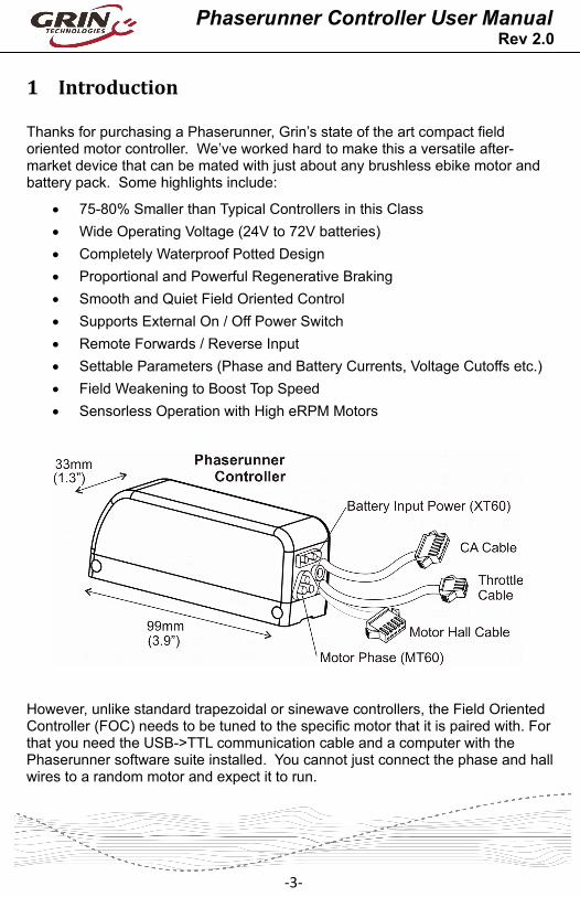
Thanks for purchasing a Phaserunner, Grin’s state of the art compact field oriented motor controller. We’ve worked hard to make this a versatile after-market device that can be mated with just about any brushless ebike motor and battery pack. Some highlights include:
75-80% Smaller than Typical Controllers in this Class
Wide Operating Voltage (24V to 72V batteries)
Completely Waterproof Potted Design
Proportional and Powerful Regenerative Braking
Smooth and Quiet Field Oriented Control
Supports External On / Off Power Switch
Remote Forwards / Reverse Input
Settable Parameters (Phase and Battery Currents, Voltage Cutoffs etc.)
Field Weakening to Boost Top Speed
Sensorless Operation with High eRPM Motors
However, unlike standard trapezoidal or sinewave controllers, the Field Oriented Controller (FOC) needs to be tuned to the specific motor that it is paired with. Forthat you need the USB->TTL communication cable and a computer with the Phaserunner software suite installed. You cannot just connect the phase and hallwires to a random motor and expect it to run.
-3-

Phaserunner Controller User ManualRev 2.0
2 Connections
The V2 Phaserunner has just 3 cables coming out of it; a 6-pin Cycle Analyst cable, a 5-pin motor hall sensor cable, and a 3-pin throttle cable. It also has embedded connectors for battery power, the motor phase power, and a communications jack.
2.1 Battery PlugThe input battery power comes from an embedded male XT60 plug. You can plug your battery pack directly into the controller if the battery leads are long enough, or use an extension cable that goes between your battery connector and the Phaserunner.
2.2 Motor PlugThe three phase motor output is delivered from a 3-pinmale MT60 connector that is well suited at handling highcurrent levels. If your motor has a long cable on it thatreaches the Phaserunner, then you can terminate it witha mating female MT60. Otherwise, a motor extensioncable will be required to connect the motor to the motorcontroller.
2.3 Throttle CableThe throttle cable is terminated in a 3-pin JST plug and is used for simple systems with just a throttle control of the ebike, with or without a V2 Cycle Analyst (CA) display. The ebrake line is also tied into this throttle signal, and with the default settings the throttle signal voltage can be brought below 0.8V to activate proportional regenerative braking, allowing for the potential use of bidirectional throttles for control of both forwards torque and braking torque.
-4-

Phaserunner Controller User ManualRev 2.0
2.4 Cycle Analyst CableThe 6-pin Cycle Analyst cable works with both V2 and V3 CA devices. The CA’s speed signal (pin 5, yellow wire) will toggle once per electrical commutation regardless of whether you have hall sensors connected.
Keep in mind if you have a V3 Cycle Analyst (CA3), then you need to plug the throttle into your CA3 and not into the controller.
2.5 Communications
Finally, there is a TRS port embedded in the back of the motor controller for connecting to a computer.
The communication standard uses a 5V TTL level serial bus, and Grin produces a 3m long TTL->USB adapter cable so that you can connect with the USB port ofa standard computer. This is the same communication cable used with the CycleAnalyst and Satiator products. You can also use 3rd party USB->Serial cables, such as FTDI’s part number TTL-232R-5V-AJ.
-5-
Phaserunner Controller User ManualRev 2.0
3 Installation and Mounting
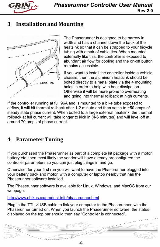
The Phaserunner is designed to be narrow in width and has a channel down the back of the heatsink so that it can be strapped to your bicycletubing with a pair of cable ties. When mounted externally like this, the controller is exposed to abundant air flow for cooling and the on-off buttonremains accessible.
If you want to install the controller inside a vehiclechassis, then the aluminum heatsink should be bolted directly to a metal plate via the 4 mounting holes in order to help with heat dissipation. Otherwise it will be more prone to overheating and going into thermal rollback at high currents.
If the controller running at full 96A and is mounted to a bike tube exposed to airflow, it will hit thermal rollback after 1-2 minute and then settle to ~50 amps of steady state phase current. When bolted to a large external heatsink, the thermalrollback at full current will take longer to kick in (4-6 minutes) and will level off at around 70 amps of phase current.
4 Parameter Tuning
If you purchased the Phaserunner as part of a complete kit package with a motor,battery etc. then most likely the vendor will have already preconfigured the controller parameters so you can just plug things in and go.
Otherwise, for your first run you will want to have the Phaserunner plugged into your battery pack and motor, with a computer or laptop nearby that has the Phaserunner software installed.
The Phaserunner software is available for Linux, Windows, and MacOS from our webpage:
http://www.ebikes.ca/product-info/phaserunner.html
Plug in the TTL->USB cable to link your computer to the Phaserunner, with the Phaserunner turned on. When you launch the Phaserunner software, the status displayed on the top bar should then say “Controller is connected”.
-6-

Phaserunner Controller User ManualRev 2.0
If you see “not connected” instead, then check that the selected serial port is correct and that the USB->TTL device shows up in your device manager as a COM port (windows) or ttyUSB (Linux), or cu.usbserial (MacOS). If your system does not recognize the USB serial adapter, then you may need to download and install the latest virtual COM port drivers from FTDI:
http://www.ftdichip.com/Drivers/VCP.htm
4.1 Motor Autotune
With the software connected, the next step is to run the Phaserunner “Autotune” routine. This will cause the motor to spin, and it is essential that your bike is propped up so that the motor can freely rotate both forwards and backwards. With a rear
hub motor be sure that the cranks can turn completely and won’t collide with a kickstand, for example, in case the initial testing spins the motor in reverse.
The start of the autotune process asks for your best guess of the motor’s kV in RPM/V, as well as the number of pole pairs in the motor. The firmware uses these initial parameters for determining the test current frequency and you shouldinput values that are close to the expected ones. For example, if you have a motor with a label that says 220 rpm 24V, then a reasonable guess for the kV is 220/24 = 9.1 RPM/V.
The effective pole pairs is a count of how many electrical cycles corresponds to one mechanical revolution of the motor, and the Phaserunner needs this information to correlate it’s electrical output frequency with the wheel speed. In a direct drive (DD) motor, it is the number of magnet pairs in the rotor, while in a geared motor you need to multiply the magnet pairs by the gear ratio.
The table below shows the effective pole pairs for many common motor series.
-7-

Phaserunner Controller User ManualRev 2.0
Table 1: Effective Pole Pairs of Common DD and Geared Hub MotorsMotor Family # PolesCrystalyte 400, Wilderness Energy 8BionX PL350 11Crystalyte 5300, 5400 12TDCM IGH 16Crysatlyte NSM, SAW 20Crysatlyte H, Crown, Nine Continent, MXUS and Other 205mm DD Motors
23
Magic Pie 3, Other 273mm DD Motors 26Bafang BPM, Bafang CST 40Outrider O2 43Bafang G01, MXUS XF07 44Bafang G02 50eZee, BMC, MAC, Puma 80
For other motors, please contact the manufacturer, open the motor to count the magnets (and gear ratio), or count the number of hall transitions that take place when you turn the wheel one revolution by hand.
Once the kV and #Poles values are put in, then a launch of the “Static Test” will produce 3 short buzzing sounds in order to determine the inductance and resistance of the motor windings, and the resulting values will be shown on the screen.
Next up, you will launch the spinning motor test, which will cause the motor to rotate at about half speed for 15 seconds. During this spinning test, the controllerwill determine the exact kV winding constant for the hub and also the pinout and timing advance of the hall sensors if they are present. If the motor spins backwards during this test, then check the box “flip motor direction on next run” and repeat the spinning motor test in the other direction.
-8-

Phaserunner Controller User ManualRev 2.0
During this spinning test, the Phaserunner will be self starting the motor in sensorless mode. If the motor fails to spin and just starts and stutters a few times, then you will need to adjust the sensorless starting parameters as described in section 4.4 until the motor is able to self start OK.
Finally, the last screen gives you an option to restore all other Phaserunner settings to their default values. We recommend doing this unless you have already made custom changes to the other settings which you want to preserve.
4.2 Battery Settings
With the controller mapped to your motor and spinning fine, you should next set the battery voltage and currentsettings to appropriate values for your pack. We recommend making the max regen voltage the same as the full charge voltage of your battery, with theregen start voltage about 0.5V less. For the low voltage rollback, you can set this to be just above the BMS cutoff
point of your battery, but if you have a Cycle Analyst we recommend leaving this
-9-

Phaserunner Controller User ManualRev 2.0
at the default 19V and use the CA’s low voltage cutoff feature instead. That way you can change it on the fly.
You should set the maximum battery current to a value that is equal to or less than what the battery is rated to deliver. Higher battery currents will result in morepower, but can also stress the battery cells resulting in shorter cycle life, and can also cause your BMS circuit to trip and shut down the pack.
If you are setting up a system with regenerative braking, then you may also need to limit the maximum regen battery current that will flow into your pack if you have a BMS circuit that shuts off if it detects excessive charge current.
4.3 Motor Phase Current and Power Settings
In addition to regulating the current flowing in and out of the battery pack, the Phaserunner can also independently control the maximum phase currents that flow to and from the motor. It is the motor phase current that both generates torque and also causes the motor windings to heat up, and at low motor speeds this phase current can be several times higher than the battery current which yousee on a Cycle Analyst.
The Max Power Limit sets an upper value on the total watts that will be allowed to flow into the hub motor. This has a similar effect to a battery current limit, but isdependent on voltage. With a 2000 watt motor power limit, you will be limited to 27 amps of battery current with a 72V pack, while you would see over 40 amps with a 48V battery.
The Max Regen Phase Current directly sets the peak braking torque of the motorat full regen. If you want strong braking effect, then set this to the full 80 or 90A, while if the maximum braking force is too intense for your liking then reduce it.
The following graph illustrates the interplay between motor phase current, batterycurrent, and motor output power for a typical setup. When riding full throttle, at low speeds you will be phase current limited, at medium speeds you will be battery current limited, and at high speeds limited by the voltage of your battery pack.
-10-

Phaserunner Controller User ManualRev 2.0
4.4 Tuning the Sensorless Self StartIf you are running in sensorless mode, then you will likely need to tweak the sensorless self start behaviour. When a brushless motor is run without hall sensors and started from a standstill, the motor controller attempts to blindly ramp up the motor RPM to a minimum speed before it can latch onto the rotation (closed loop).
It does this by first injecting a static current into the phase windings to orient the motor in a known position, and then it rotates this field faster and faster until reaching the Autostart Max RPM point.
As a starting point, you should use an autostart injection current similar to your maximum phase current, an Autostart Max RPM about 5-10% of the running
-11-

Phaserunner Controller User ManualRev 2.0
motor RPM, and a Spinup time anywhere from 0.3 to 1.5 seconds depending on how easily the motor can propel the bike up to speed. On bikes that you pedal assist to help start, then a short 0.2-0.3 second ramp will often work best, while amuch longer ramp is required if you need to get going with zero pedal input.
If the autostart ramp is too aggressive or the Autostart Max RPM is too low, then on hitting the throttle you will feel the motor repeatedly trying to start again and again. You may also generate faults such as instantaneous phase over-current error. If you are getting phase over-current faults during the sensorless start, then you will usually need to increase the current regulator bandwidth and/or the PLL bandwidth parameters.
4.5 Throttle and Regen Voltage MapsUnlike most ebike controllers where the throttle signal controls the effective voltage and hence unloaded RPM of the motor, with a Phaserunner the throttle isdirectly controlling the motor torque. If you pick the motor off the ground and give it just a tiny amount of throttle, it will still spin up to full RPM as there is no load on the motor. Meanwhile if you are riding the vehicle and apply partial throttle, you will get a steady torque from the motor which stays constant even as the vehicle speeds up or slows down. This is different from standard ebike controllers, where the throttle more directly controls motor speed.
By default, the Phaserunner will be configured so that active throttle startsat 1.2V, and full throttle is reached at 3.5V, which is broadly compatible with Hall Effect ebike throttles. The Phaserunner has an analog ebrake line which is tied to the throttle line, and the regen voltage is mapped so that regenerative braking starts at 0.8V and then reaches maximum intensity at 0.0V.
With the brake and throttle lines tied together this way, the Phaserunner can support variable regen through bidirectional throttles or a V3 Cycle Analyst, with just a single wire for forwards and braking torque.
-12-

Phaserunner Controller User ManualRev 2.0
4.6 Field Weakening for Speed BoostOne useful feature of the Phaserunner as a field oriented controller is the ability to boost the top speed of your motor beyond what is normally possible from your battery voltage. This is done through the injection of field weakening current that is perpendicular to the torque producing current.
The exact speed increase for a given field weakening current will depend on the characteristics of your particular motor, and increasing the speed this way is less efficient than using a higher voltage pack or a faster motor winding. But for a speed boost of 15-20%, the additional losses are quite reasonable considering the gains.
The graph below shows the measured motor RPM (black line) as a function of the field weakening amps for a large direct drive hub motor. The yellow line is theno-load current draw, which reflects the amount of extra power lost due to the field weakening. At 20 amps of field weakening, the motor speed increased from 310 rpm to 380 rpm, while the no load current draw is still just under 3 amps.
-13-

Phaserunner Controller User ManualRev 2.0
5 Hidden WiresThere are several additional wires inside the throttle cable that will be revealed if you pull back the heatshrink, including forwards/reverse control, a remote switch input, and an analog brake signal.
5.1 Reverse ModeThe brown forwards / reverse wire is useful in certain trike andquad situations when you want to back up under power. To use this, you will need to hook up a switch that shorts the signal wire to a ground wire. In the Phaserunner software you can independently limit the reverse speed so that the vehicle does not shoot backwards at full throttle.
5.2 Remote Power SwitchThe two button wires allow you to hook up aremote switch if you want the ability to turnthe system on and off without having to turnoff battery power. These two wires contain thefull battery voltage so be careful not to shortthem against any signal lines.
5.3 Separate Ebrake Input
Finally, you will notice that the throttle signal cable has both blue (analog brake) and green (throttle) wires crimped together on the same pin. If you want to have separate signals to control your braking torque and your motoring torque (say two throttles, or an ebrake lever that has a proportional voltage signal on it), then you can separate the green and blue wires from this pin and send independent signals to each of them.
-14-

Phaserunner Controller User ManualRev 2.0
6 Cycle Analyst Settings
The Phaserunner controller uses a 1.00 mOhm precision shunt resistor for current sensing, so to have an accurate readout of your current you only need to make sure that the CA’s RShunt is set o 1.000 mOhm, which is conveniently the default value.
Because the Phaserunner uses a torque throttle rather than a voltage throttle, theoptimized throttle output settings on a V3 CA device may differ from what you might use with a conventional ebike controller. The ramp up and ramp down rates now control the rate at which motor torque is increased or decreased, and can be higher values for similar smoothing effects.
7 LED CodesThe embedded LED on the side of the controller provides a useful status indicator if there are any fault situations detected. Some faults will clear automatically when the condition is gone (such as throttle voltage outside of range), while others will require turning the controller off and on first.
Table 2: Phaserunner LED Flash Codes1-1 Controller Over Voltage1-2 Phase Over Current1-3 Current Sensor Calibration1-4 Current Sensor Over Current1-5 Controller Over Temperature1-6 Motor Hall Sensor Fault1-7 Controller Under Voltage1-8 POST Static Gate Test Outside Range2-1 Network Communications Timeout2-2 Instantaneous Phase Overcurrent2-4 Throttle Voltage Outside of Range2-5 Instantaneous Controller Over Voltage2-6 Internal Error2-7 POST Dynamic Gate Test Outside Range2-8 Instantaneous Controller Under Voltage3-1 Parameter CRC Error3-2 Current Scaling Error3-3 Voltage Scaling Error3-7 Hall Stall
-15-

Phaserunner Controller User ManualRev 2.0
8 Specifications
8.1 Electrical
Peak Battery Current Programmable up to 96A* Suggested 40A MaxPeak Phase Current Programmable up to 96A*Peak Regen Phase Current Programmable up to 96A*Continuous Phase Current 45-50 Amps*, 70 Amps with Additional HeatsinkPhase Current Rollback Temp 90°C Internal Temp (casing ~70°C)Mosfets 100V, 2.5 mOhmMax Battery Voltage 90V (21s Lithium, 24s LiFePO4)Min Battery Voltage 19V (6s Lithium, 7s LiFePO4)eRPM Limit Not recommended above 60,000 ePRM, though it
will continue to function beyond this. Max Current from CA-DP Plug 1.5 Amps (Auto Shutdown at Higher Currents)RShunt for Cycle Analyst 1.000 mΩ
* Thermal rollback will typically kick in after 1-2 minutes of peak phase current, and current will then automatically reduce to maintain controller rollback temperature.
8.2 Mechanical
Dimensions LxWxH 99 x 33 x 40 mmHeatsink Bolt Holes M4x0.8, 5mm Deep, 26.6mm x 80.5mm SpacingWeight 0.24 – 0.5kg (Depending on Cable Length)DC Battery Connector Amass XT60Motor Phase Connector Amass MT60Signal Connectors Female JST-SM SeriesCommunication Plug 1/8” TRS JackWaterproofing 100% Potted Electronics, Connectors Not So Much
8.3 Connector Pinout
** Ebrake / Throttle wires can be separated if desired*** Caution with old small screen Cycle Analysts, additional diode is required
in Throt line to prevent full power when plugged in.
-16-