THE BEIJING NATIONAL STADIUM SPECIAL ISSUE … · THE BEIJING NATIONAL STADIUM SPECIAL ISSUE 1/2009...
52
1/2009 THE BEIJING NATIONAL STADIUM SPECIAL ISSUE The Arup Journal
-
Upload
nguyencong -
Category
Documents
-
view
254 -
download
5
Transcript of THE BEIJING NATIONAL STADIUM SPECIAL ISSUE … · THE BEIJING NATIONAL STADIUM SPECIAL ISSUE 1/2009...
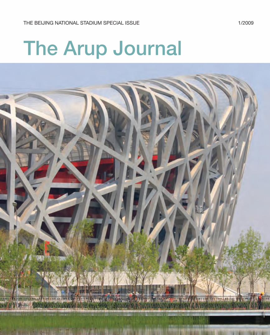
1/2009THE BEIJING NATIONAL STADIUM SPECIAL ISSUE
The Arup Journal
30223_Arup.indd 1 28/4/09 12:55:00
2 The Arup Journal 1/2009
Contents 4 Introduction Stephen Burrows
5 Competition, team, and site Tony Choi Michael Kwok
Sports architecture
8 The architectural design concept
J Parrish
The main roof
16 The Stadium geometry Stephen Burrows Martin Simpson
20 Analysis model and results Kylie Lam Thomas Lam
24 Seismic design of the roof Xiaonian Duan Goman Ho
28 The retractable roof design John Lyle
The bowl
32 Layout and analysis model Tony Choi Thomas Lam
34 Seismic design of the bowl Xiaonian Duan Goman Ho
Specialist engineering design
36 Roof cladding and acoustic ceiling
Tony Choi
37 Wind conditions in the Stadium and external plaza
Alex To
38 Thermal comfort in the Stadium Rumin Yin
40 Fire engineering concepts Mingchun Luo
41 Building services design Lewis Shiu
44 The lighting concept design Jeff Shaw
Rogier van der Heide
Construction and conclusion
48 Completing the programme Tony Choi Michael Kwok
49 Constructing a stadium
50 Credits
30223_Arup.indd 2 28/4/09 15:38:59
3The Arup Journal 1/2009
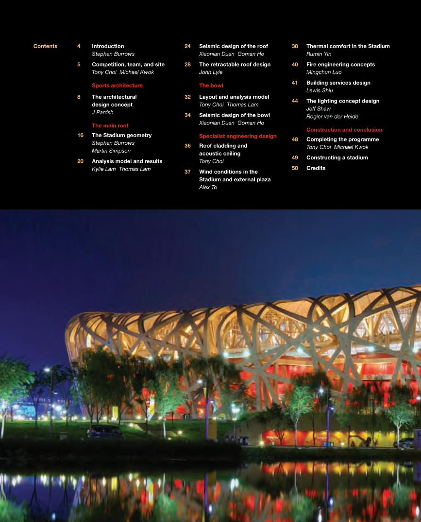
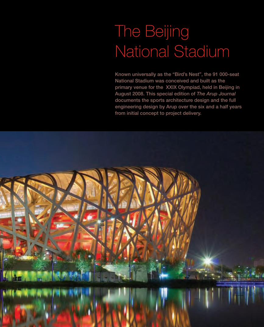
The Beijing National StadiumKnown universally as the “Bird’s Nest”, the 91 000-seat National Stadium was conceived and built as the primary venue for the XXIX Olympiad, held in Beijing in August 2008. This special edition of The Arup Journal documents the sports architecture design and the full engineering design by Arup over the six and a half years from initial concept to project delivery.
30223_Arup.indd 3 28/4/09 15:39:04
4 The Arup Journal 1/2009
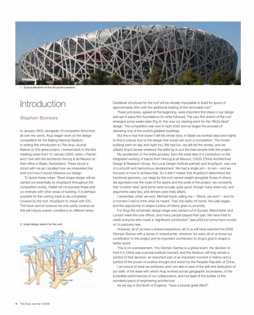
Cantilever structures for the roof will be virtually impossible to build for spans of approximately 60m with the additional loading of the removable roof.”
These principles, agreed at the beginning, were important fi rst steps in our design and set in place fi rm foundations for what followed. The very fi rst sketch of the roof emerged some weeks later (Fig 2): this was our starting point for the “Bird’s Nest” design. The competition was won in April 2003 and so began the process of delivering one of the world’s greatest buildings.
But the e-mail trail doesn’t tell the whole story. In Basle we worked days and nights to fi nd a cultural clue to the design that would win such a competition. The model-building went on day and night too. We had fun, we still tell the stories, and we utilised Arup’s power wherever the skills lay to put the best people onto the project.
My recollection of the entire process, from the initial idea of a consortium to the integrated working of teams from Herzog & de Meuron, CADG (China Architectural Design & Research Group, the Local Design Institute partner) and ArupSport, was one of a smooth and harmonious development. We had a single aim – to win – and we focused on how to achieve that. So it didn’t matter that ArupSport determined the functional geometry, our ideas for the roof carried weight alongside those of others, we agonised over the scale of the spans and the scale of the project, we constantly had “a better idea” (and some were actually quite good, though many were not), and arguments were few, and dinners were lively affairs.
I remember, when we won, Michael Kwok calling me – ”Steve, we won!” – and for a moment I had to think what he meant. Then the reality hit home, the calls began, and the opportunity to shape a piece of history grew to enormity.
For Arup the schematic design stage was carried out in Europe. Manchester and London were the core offi ces, and many people played their part. We have tried to credit everyone who made a “signifi cant contribution” (see p50) but some have moved on to pastures new.
However, all of us have a shared experience; all of us will have watched the 2008 Olympic Games with a sense of shared pride, wherever we were; all of us know our contribution to the project and its important contribution to Arup’s goal to shape a better world.
This is no overstatement. The Olympic Games is a global event, the decision to hold it in China was a pivotal political moment, and the Stadium will long remain a symbol of that decision, an important part of an important moment in history and a symbol of the power of positive thought and action by the Peoples Republic of China.
I am proud of what we achieved, and I am also in awe of the skill and dedication of our staff, of the ease with which Arup worked across geographic boundaries, of the incredible performances of our collaborators, and not least of the builder of this wonderful piece of engineering architecture.
As we say in the North of England, “’twas a bloody great effort!”
In January 2003, alongside 13 competitor fi rms from all over the world, Arup began work on the design competition for the Beijing National Stadium. In writing this introduction to The Arup Journal feature on this great project, I looked back to the fi rst meeting notes from 10 January 2003, when J Parrish and I met with the architects Herzog & de Meuron at their offi ce in Basle, Switzerland. These struck a chord with me as I recalled how we interpreted the brief and how it would infl uence our design.
To quote these notes: “Bowl shape design will be carried out essentially by ArupSport throughout the competition works, HdeM will incorporate these and co-ordinate with other areas of building. It is perhaps possible for the running track to be completely covered by the roof, ArupSport to check with IOC. The track cannot however be only partly covered as this will induce uneven conditions on different lanes.
IntroductionStephen Burrows
2. Initial design sketch for the roof.
Structuraldepth oftrusses
Bottom mat
Top mat
1. Typical elevation of the structure’s exterior.
30223_Arup.indd 4 28/4/09 12:55:17
5The Arup Journal 1/2009
National
Aquatics
Centre
National
Indoor
Stadium
National
Stadium
Sports Centre
Gymnasium
Ethnic
Culture
Park
Olympics
Village
Chinese
Science &
Technology
Museum
Beijing
Olympics
Park
Olympic
Green
Fencing Hall
North 4th Ring Road
The design competition
Selecting the winning scheme for the National Stadium also involved the citizens of
Beijing. All 13 competition schemes were displayed at the Beijing Exhibition Centre in
March 2003, attracting thousands of visitors, and alongside the deliberations of the
international jury panel, votes by the general public were also taken into account.
By the end of March 2003, it was announced that the “Bird’s Nest” scheme was
selected as the winner, both by the jury panel and by public voting.
However, the route from winning the design competition to winning the contract
as designer for the implementation of the project was not a simple journey.
In parallel with the design competition, the Beijing Development Planning
Commission (BDPC) called for an ownership tender for the National Stadium.
The bid winner was to join the Beijing state-owned Assets Management Corporation
(BSAM) to form the project company, which would be responsible for the investment,
construction, operation, and transfer of the project. A consortium led by CITIC was
selected as the successful bidder, and duly joined with BSAM to form the project
company National Stadium Co Ltd, which became Arup’s client for the project.
Negotiation of the design contract between the design consortium (Herzog &
De Meuron, Arup, and CADG) and the client started in July 2003, and the tough
commercial negotiation took more than four months to conclude with contract signed
in early December 2003. Concurrently, the schematic design was progressed at fast
pace, with the “Bird’s Nest” groundbreaking ceremony held on 24 December 2003.
The Arup team
Arup’s success in delivering the project was truly a result of team effort and global
collaboration, with everyone working seamlessly as “one Arup”. The ArupSport teams
in London and in Manchester, the teams in Beijing, Hong Kong and Shenzhen, and
the London Advanced Technology and Lighting groups, all gave of their very best.
Within weeks of commencing the schematic design stage, engineers from Beijing and
Hong Kong were assigned to the Manchester office to work with the team there.
At the same time, another team was mobilised in the Beijing office to liaise and
co-ordinate closely with the client, with CADG, and with local authorities. During the
preliminary design stage, some UK members stayed in Beijing to work with the team
at critical stages to ensure smooth implementation. Arup’s ability to mobilise global
expertise and deliver locally was key to the success of the project.
Arup’s scope of service covered sports architecture and all engineering disciplines
including structural, mechanical, electrical, public health, wind, fire, and seismic
engineering, environmental and microclimate studies, acoustics, and lighting design.
Arup global expertise was deployed to achieve a world-class, state-of-the-art design.
The firm was responsible for schematic design and preliminary design for the above
scope, whilst CADG was responsible for construction documentation.
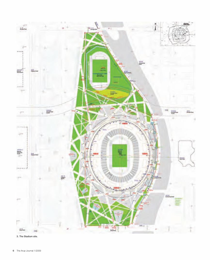
Site profile
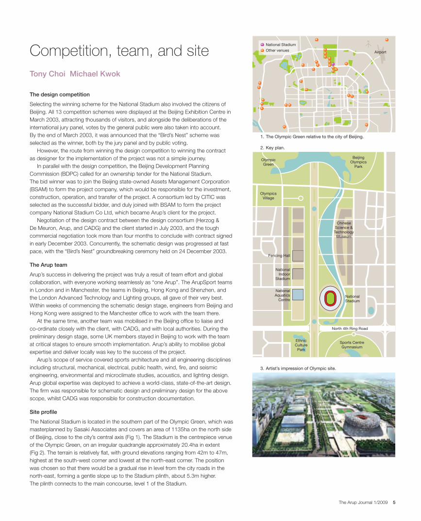
The National Stadium is located in the southern part of the Olympic Green, which was
masterplanned by Sasaki Associates and covers an area of 1135ha on the north side
of Beijing, close to the city’s central axis (Fig 1). The Stadium is the centrepiece venue
of the Olympic Green, on an irregular quadrangle approximately 20.4ha in extent
(Fig 2). The terrain is relatively flat, with ground elevations ranging from 42m to 47m,
highest at the south-west corner and lowest at the north-east corner. The position
was chosen so that there would be a gradual rise in level from the city roads in the
north-east, forming a gentle slope up to the Stadium plinth, about 5.3m higher.
The plinth connects to the main concourse, level 1 of the Stadium.
Competition, team, and siteTony Choi Michael Kwok
2. Key plan.
3. Artist’s impression of Olympic site.
2. Key plan.3. Site plan.
National Stadium
AirportOther venues
1. The Olympic Green relative to the city of Beijing.
30223_Arup.indd 5 28/4/09 12:55:19
6 The Arup Journal 1/2009
3. The Stadium site.
30223_Arup.indd 6 28/4/09 12:55:29
7The Arup Journal 1/2009
Sports architecture
30223_Arup.indd 7 28/4/09 12:55:33
8 The Arup Journal 1/2009
Introduction
At the time the architectural competition for the Beijing National Stadium was announced, Herzog & de Meuron and ArupSport (Arup’s multidisciplinary practice specialising in sports architecture) were already working together on the Allianz Arena in Munich1. This successful creative partnership was based on a shared desire to innovate: Herzog & de Meuron in creating unique buildings with strong local cultural resonances, and Arup in designing stadiums that perform ever better for spectators, athletes, and operators. As already noted, for the Beijing competition the two practices joined forces with one of the leading Chinese Design Institutes, CADG.
Within this integrated team, the architects at ArupSport were responsible in particular for the bowl, the concourses, and the spectator facilities, which together defined the form of the Stadium. They also produced an initial optimised structural proposal for the roof and envelope, which Herzog & de Meuron then developed. CADG provided vital local expertise during the competition and scheme design, and then took the baton for the final stages of the project, liaising with the local authorities, producing construction information and monitoring the works on site. Backed by Arup’s engineering expertise, the competition team was able to submit a highly developed, fully realisable architectural concept. As a result, despite some significant changes to the brief, the form of the built Stadium is very close to the original winning design.
The architectural design concept
“I was delighted that the competition areas did everything that was set out for them to do. The path from drop-off for athletes to the warm-up area, with access to the Technical Information Centre for Team staff along the route; the fact that there were separate corridors to make sure that athletes making their way from the Call Room to the track could do so securely and without being disturbed by other athletes or coaches, without minimising space for others preparing themselves, and the space provided for athletes and staff to move around, made it the ideal stadium for the Paralympics Games. The fact that all of these spaces were absolutely accessible for athletes and staff using wheelchairs made it a delight to use. Added to this, the fact that spectator areas provided enough good access for those using wheelchairs was superb.” Chris Cohen: Chairman of IPC Athletics.
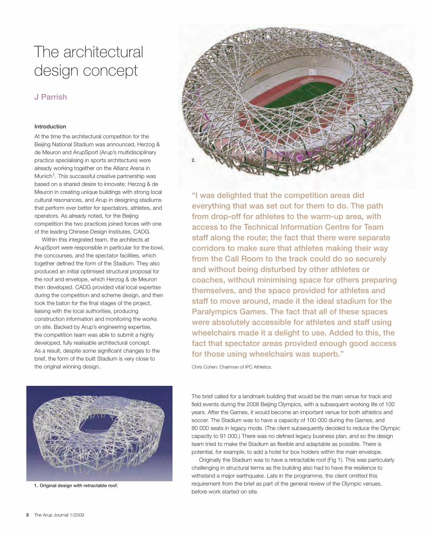
The brief called for a landmark building that would be the main venue for track and field events during the 2008 Beijing Olympics, with a subsequent working life of 100 years. After the Games, it would become an important venue for both athletics and soccer. The Stadium was to have a capacity of 100 000 during the Games, and 80 000 seats in legacy mode. (The client subsequently decided to reduce the Olympic capacity to 91 000.) There was no defined legacy business plan, and so the design team tried to make the Stadium as flexible and adaptable as possible. There is potential, for example, to add a hotel for box holders within the main envelope.
Originally the Stadium was to have a retractable roof (Fig 1). This was particularly challenging in structural terms as the building also had to have the resilience to withstand a major earthquake. Late in the programme, the client omitted this requirement from the brief as part of the general review of the Olympic venues, before work started on site.
J Parrish
1. Original design with retractable roof.
2.
30223_Arup.indd 8 28/4/09 12:55:38
9The Arup Journal 1/2009
Bowl design involves a skilful balancing of several key criteria. Most importantly, spectators want to be as close as possible to the action and to have a good view of the field, while the stadium developer needs to accommodate a certain number of seats within a defined budget.
These requirements often conflict. For example, more space between rows creates better sightlines but draws spectators further away from the field and results in a larger stadium with increased construction costs. Even a tiny adjustment to the configuration of the seats can have a huge impact on the overall design and cost of the building. To find the optimum solution, it is essential to set priorities.
The bowl
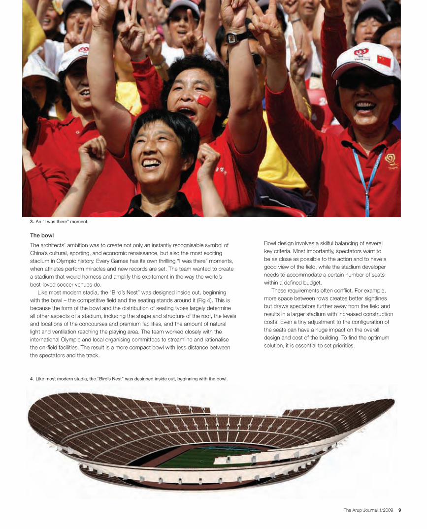
The architects’ ambition was to create not only an instantly recognisable symbol of China’s cultural, sporting, and economic renaissance, but also the most exciting stadium in Olympic history. Every Games has its own thrilling “I was there” moments, when athletes perform miracles and new records are set. The team wanted to create a stadium that would harness and amplify this excitement in the way the world’s best-loved soccer venues do.
Like most modern stadia, the “Bird’s Nest” was designed inside out, beginning with the bowl – the competitive field and the seating stands around it (Fig 4). This is because the form of the bowl and the distribution of seating types largely determine all other aspects of a stadium, including the shape and structure of the roof, the levels and locations of the concourses and premium facilities, and the amount of natural light and ventilation reaching the playing area. The team worked closely with the international Olympic and local organising committees to streamline and rationalise the on-field facilities. The result is a more compact bowl with less distance between the spectators and the track.
3. An “I was there” moment.
4. Like most modern stadia, the “Bird’s Nest” was designed inside out, beginning with the bowl.
30223_Arup.indd 9 28/4/09 12:55:43
10 The Arup Journal 1/2009
This complex process has been transformed in recent years by parametric relationship modelling. Using powerful computer software, designers can quickly generate the initial form of a stadium within defined parameters such as geometric constraints, environmental factors, and the limitations of construction materials.
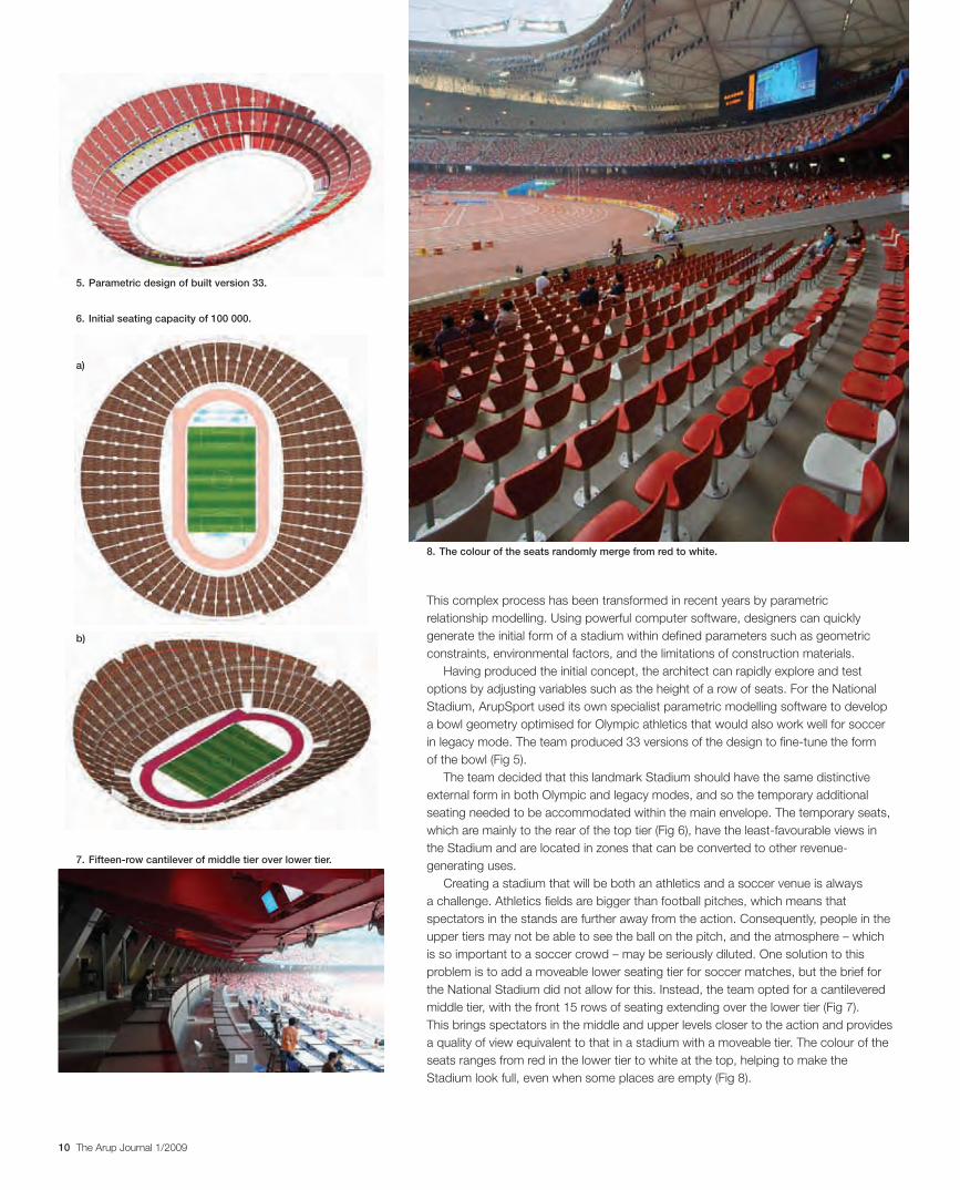
Having produced the initial concept, the architect can rapidly explore and test options by adjusting variables such as the height of a row of seats. For the National Stadium, ArupSport used its own specialist parametric modelling software to develop a bowl geometry optimised for Olympic athletics that would also work well for soccer in legacy mode. The team produced 33 versions of the design to fine-tune the form of the bowl (Fig 5).
The team decided that this landmark Stadium should have the same distinctive external form in both Olympic and legacy modes, and so the temporary additional seating needed to be accommodated within the main envelope. The temporary seats, which are mainly to the rear of the top tier (Fig 6), have the least-favourable views in the Stadium and are located in zones that can be converted to other revenue-generating uses.
Creating a stadium that will be both an athletics and a soccer venue is always a challenge. Athletics fields are bigger than football pitches, which means that spectators in the stands are further away from the action. Consequently, people in the upper tiers may not be able to see the ball on the pitch, and the atmosphere – which is so important to a soccer crowd – may be seriously diluted. One solution to this problem is to add a moveable lower seating tier for soccer matches, but the brief for the National Stadium did not allow for this. Instead, the team opted for a cantilevered middle tier, with the front 15 rows of seating extending over the lower tier (Fig 7). This brings spectators in the middle and upper levels closer to the action and provides a quality of view equivalent to that in a stadium with a moveable tier. The colour of the seats ranges from red in the lower tier to white at the top, helping to make the Stadium look full, even when some places are empty (Fig 8).
5. Parametric design of built version 33.
8. The colour of the seats randomly merge from red to white.
a)
7. Fifteen-row cantilever of middle tier over lower tier.
6. Initial seating capacity of 100 000.
b)
30223_Arup.indd 10 28/4/09 12:55:55
11The Arup Journal 1/2009
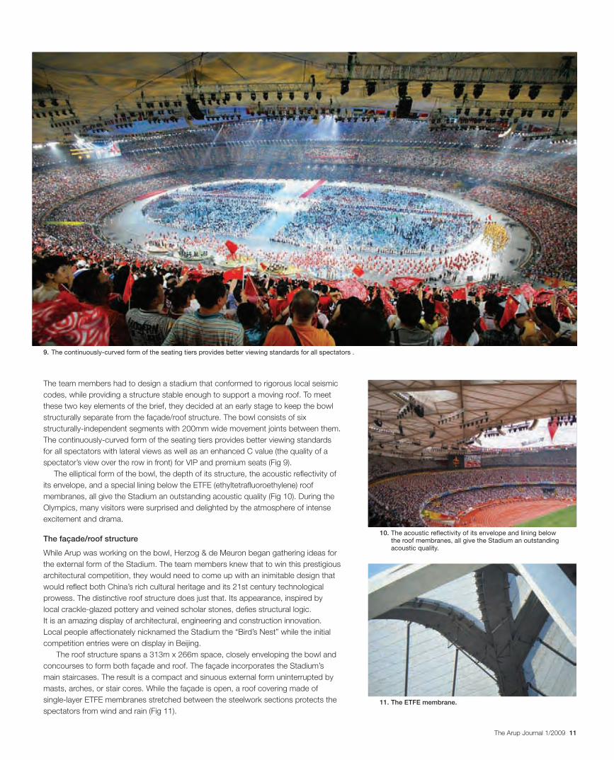
The team members had to design a stadium that conformed to rigorous local seismic codes, while providing a structure stable enough to support a moving roof. To meet these two key elements of the brief, they decided at an early stage to keep the bowl structurally separate from the façade/roof structure. The bowl consists of six structurally-independent segments with 200mm wide movement joints between them. The continuously-curved form of the seating tiers provides better viewing standards for all spectators with lateral views as well as an enhanced C value (the quality of a spectator’s view over the row in front) for VIP and premium seats (Fig 9).
The elliptical form of the bowl, the depth of its structure, the acoustic reflectivity of its envelope, and a special lining below the ETFE (ethyltetrafluoroethylene) roof membranes, all give the Stadium an outstanding acoustic quality (Fig 10). During the Olympics, many visitors were surprised and delighted by the atmosphere of intense excitement and drama.
The façade/roof structure
While Arup was working on the bowl, Herzog & de Meuron began gathering ideas for the external form of the Stadium. The team members knew that to win this prestigious architectural competition, they would need to come up with an inimitable design that would reflect both China’s rich cultural heritage and its 21st century technological prowess. The distinctive roof structure does just that. Its appearance, inspired by local crackle-glazed pottery and veined scholar stones, defies structural logic. It is an amazing display of architectural, engineering and construction innovation. Local people affectionately nicknamed the Stadium the “Bird’s Nest” while the initial competition entries were on display in Beijing.
The roof structure spans a 313m x 266m space, closely enveloping the bowl and concourses to form both façade and roof. The façade incorporates the Stadium’s main staircases. The result is a compact and sinuous external form uninterrupted by masts, arches, or stair cores. While the façade is open, a roof covering made of single-layer ETFE membranes stretched between the steelwork sections protects the spectators from wind and rain (Fig 11).
9. The continuously-curved form of the seating tiers provides better viewing standards for all spectators .
10. The acoustic reflectivity of its envelope and lining below the roof membranes, all give the Stadium an outstanding acoustic quality.
11. The ETFE membrane.
30223_Arup.indd 11 28/4/09 12:56:01
12 The Arup Journal 1/2009
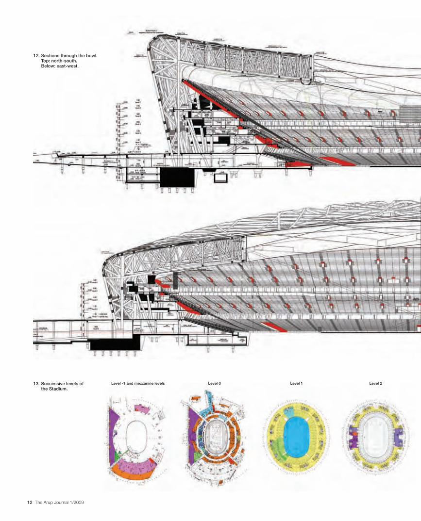
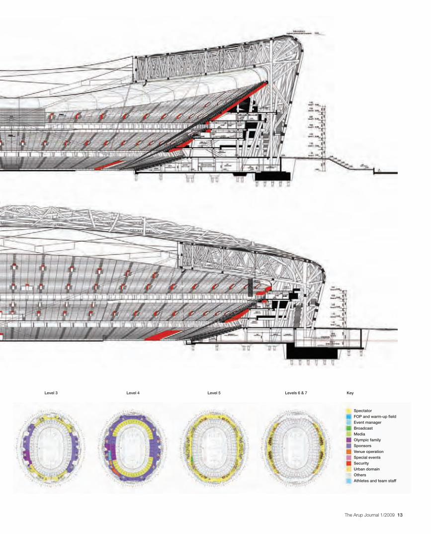
12. Sections through the bowl. Top: north-south. Below: east-west.
Level -1 and mezzanine levels Level 0 Level 1 Level 213. Successive levels of the Stadium.
30223_Arup.indd 12 28/4/09 12:56:15
13The Arup Journal 1/2009
Level 4 Level 5Level 3 Levels 6 & 7 Key
Spectator
FOP and warm-up field
Event manager
Broadcast
Media
Olympic family
Sponsors
Venue operation
Special events
Security
Urban domain
Others
Athletes and team staff
30223_Arup.indd 13 28/4/09 12:56:24
14 The Arup Journal 1/2009
Reference
(1) BURROWS, S, et al. The Allianz Arena: A new football stadium for Munich, Germany. The Arup Journal, 41(1), pp24-31, 1/2006.
We gratefully acknowledge the assistance of Felicity Parsons, independent architectural writer based in London, in preparing this article.
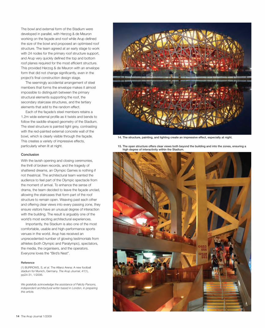
The bowl and external form of the Stadium were developed in parallel, with Herzog & de Meuron working on the façade and roof while Arup defined the size of the bowl and proposed an optimised roof structure. The team agreed at an early stage to work with 24 nodes for the primary roof structure support, and Arup very quickly defined the top and bottom roof planes required for the most efficient structure. This provided Herzog & de Meuron with an envelope form that did not change significantly, even in the project’s final construction design stage.
The seemingly accidental arrangement of steel members that forms the envelope makes it almost impossible to distinguish between the primary structural elements supporting the roof, the secondary staircase structures, and the tertiary elements that add to the random effect.
Each of the façade’s steel members retains a 1.2m wide external profile as it twists and bends to follow the saddle-shaped geometry of the Stadium. The steel structure is painted light grey, contrasting with the red-painted external concrete wall of the bowl, which is clearly visible through the façade. This creates a variety of impressive effects, particularly when lit at night.
Conclusion
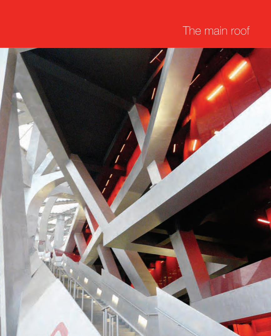
With the lavish opening and closing ceremonies, the thrill of broken records, and the tragedy of shattered dreams, an Olympic Games is nothing if not theatrical. The architectural team wanted the audience to feel part of the Olympic spectacle from the moment of arrival. To enhance the sense of drama, the team decided to leave the façade unclad, allowing the staircases that form part of the roof structure to remain open. Weaving past each other and offering clear views into every passing zone, they ensure visitors have an unusual degree of interaction with the building. The result is arguably one of the world’s most exciting architectural experiences.
Importantly, the Stadium is also one of the most comfortable, usable and high-performance sports venues in the world. Arup has received an unprecedented number of glowing testimonials from athletes (both Olympic and Paralympic), spectators, the media, the organisers, and the operators. Everyone loves the “Bird’s Nest”.
14. The structure, painting, and lighting create an impressive effect, especially at night.
15. The open structure offers clear views both beyond the building and into the zones, ensuring a high degree of interactivity within the Stadium.
30223_Arup.indd 14 28/4/09 12:56:33
15The Arup Journal 1/2009
The main roof
30223_Arup.indd 15 28/4/09 12:56:37
16 The Arup Journal 1/2009
Introduction
The overall shape and form of the National Stadium directly responded to two requirements of the initial project brief – it had to have a moving roof, and it should be designed to withstand seismic events twice the magnitude of the 1976 Great Tangshan earthquake that killed more than a quarter of a million people in Beijing.
This would not be the first stadium with a moving roof to be constructed in a seismic zone, nor would it be the first for Arup (the firm engineered the 45 000-seat Toyota Stadium, Japan, and the 42 000-capacity Miller Park baseball stadium in Milwaukee, USA1). It would, however, be the largest, with an initial capacity of over 100 000 spectators.
In addition to the requirements of the brief, the team from ArupSport and Herzog & de Meuron also wanted to reduce the Stadium’s visual mass and avoid such structural solutions as masts and arches. So instead, the team opted to wrap the roof structure closely to the geometric constraints of the seating bowl and the concourses (Figs 1, 2).
Having adopted a philosophy for the building’s form, the next task was to create a structural solution that conformed to the requirements of brief, location, and aesthetics. The answer lay in separating the roof structure from the bowl structure. The former could be a complete entity with no movement joints, providing a stable platform for the moving roof and thereby greatly simplifying the mechanisation. The bowl structure could also be simplified, as there would be no significant interface with the roof. The resulting bowl structure was ultimately realised as six completely separate buildings each with its own stability system, and 200mm movement joints between each building.
Original inspiration
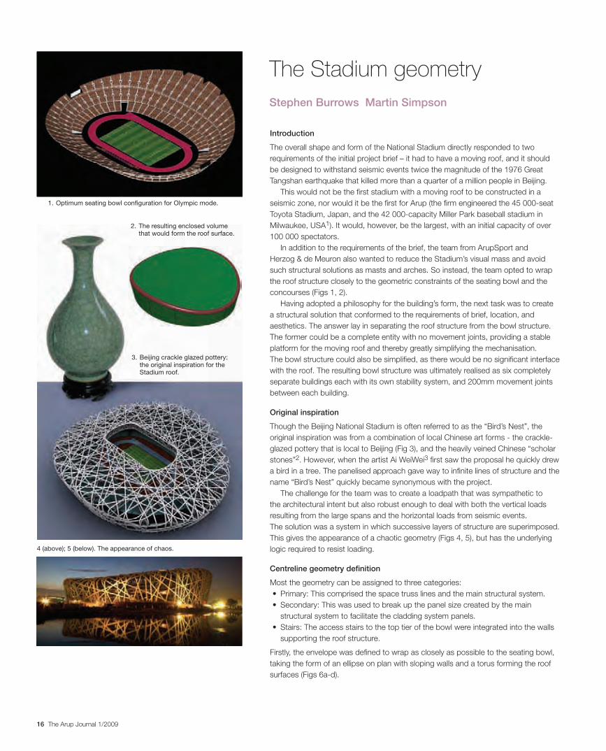
Though the Beijing National Stadium is often referred to as the “Bird’s Nest”, the original inspiration was from a combination of local Chinese art forms - the crackle-glazed pottery that is local to Beijing (Fig 3), and the heavily veined Chinese “scholar stones”2. However, when the artist Ai WeiWei3 first saw the proposal he quickly drew a bird in a tree. The panelised approach gave way to infinite lines of structure and the name “Bird’s Nest” quickly became synonymous with the project.
The challenge for the team was to create a loadpath that was sympathetic to the architectural intent but also robust enough to deal with both the vertical loads resulting from the large spans and the horizontal loads from seismic events. The solution was a system in which successive layers of structure are superimposed. This gives the appearance of a chaotic geometry (Figs 4, 5), but has the underlying logic required to resist loading.
Centreline geometry definition
Most the geometry can be assigned to three categories:• Primary:Thiscomprisedthespacetrusslinesandthemainstructuralsystem.• Secondary:Thiswasusedtobreakupthepanelsizecreatedbythemain
structural system to facilitate the cladding system panels. • Stairs:Theaccessstairstothetoptierofthebowlwereintegratedintothewalls
supporting the roof structure.
Firstly, the envelope was defined to wrap as closely as possible to the seating bowl, taking the form of an ellipse on plan with sloping walls and a torus forming the roof surfaces (Figs 6a-d).
The Stadium geometry Stephen Burrows Martin Simpson
1. Optimum seating bowl configuration for Olympic mode.
2. The resulting enclosed volume that would form the roof surface.
3. Beijing crackle glazed pottery: the original inspiration for the Stadium roof.
4 (above); 5 (below). The appearance of chaos.
30223_Arup.indd 16 28/4/09 12:56:41
17The Arup Journal 1/2009
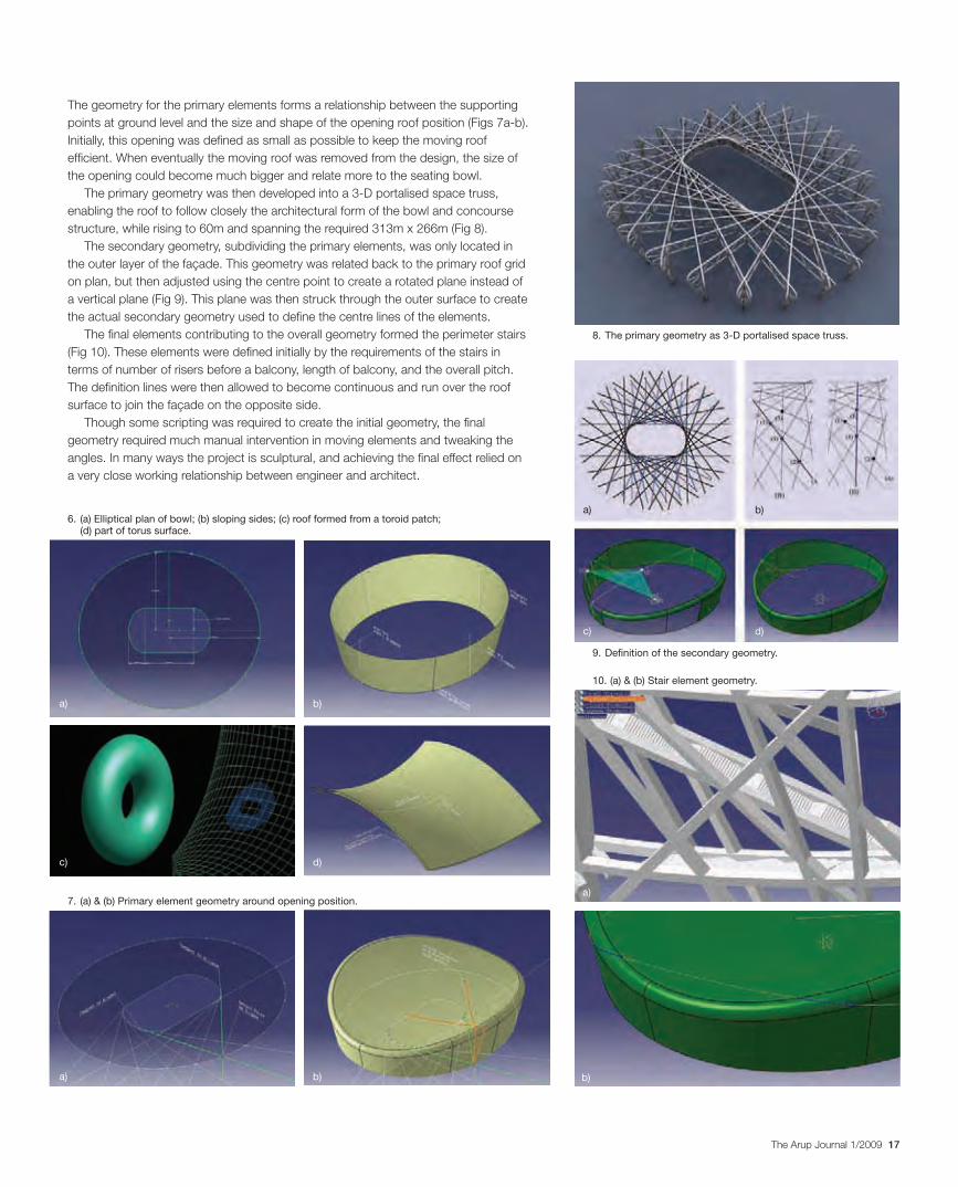
The geometry for the primary elements forms a relationship between the supporting points at ground level and the size and shape of the opening roof position (Figs 7a-b). Initially, this opening was defined as small as possible to keep the moving roof efficient. When eventually the moving roof was removed from the design, the size of the opening could become much bigger and relate more to the seating bowl.
The primary geometry was then developed into a 3-D portalised space truss, enabling the roof to follow closely the architectural form of the bowl and concourse structure, while rising to 60m and spanning the required 313m x 266m (Fig 8).
The secondary geometry, subdividing the primary elements, was only located in the outer layer of the façade. This geometry was related back to the primary roof grid on plan, but then adjusted using the centre point to create a rotated plane instead of a vertical plane (Fig 9). This plane was then struck through the outer surface to create the actual secondary geometry used to define the centre lines of the elements.
The final elements contributing to the overall geometry formed the perimeter stairs (Fig 10). These elements were defined initially by the requirements of the stairs in terms of number of risers before a balcony, length of balcony, and the overall pitch. The definition lines were then allowed to become continuous and run over the roof surface to join the façade on the opposite side.
Though some scripting was required to create the initial geometry, the final geometry required much manual intervention in moving elements and tweaking the angles. In many ways the project is sculptural, and achieving the final effect relied on a very close working relationship between engineer and architect.
9. Definition of the secondary geometry.
10. (a) & (b) Stair element geometry.
8. The primary geometry as 3-D portalised space truss.
6. (a) Elliptical plan of bowl; (b) sloping sides; (c) roof formed from a toroid patch; (d) part of torus surface.
7. (a) & (b) Primary element geometry around opening position.
a)
c)
c)
a)
b)
d)
d)
b)
a)
a)
b)
b)
30223_Arup.indd 17 28/4/09 12:56:46
18 The Arup Journal 1/2009
Twisted elements
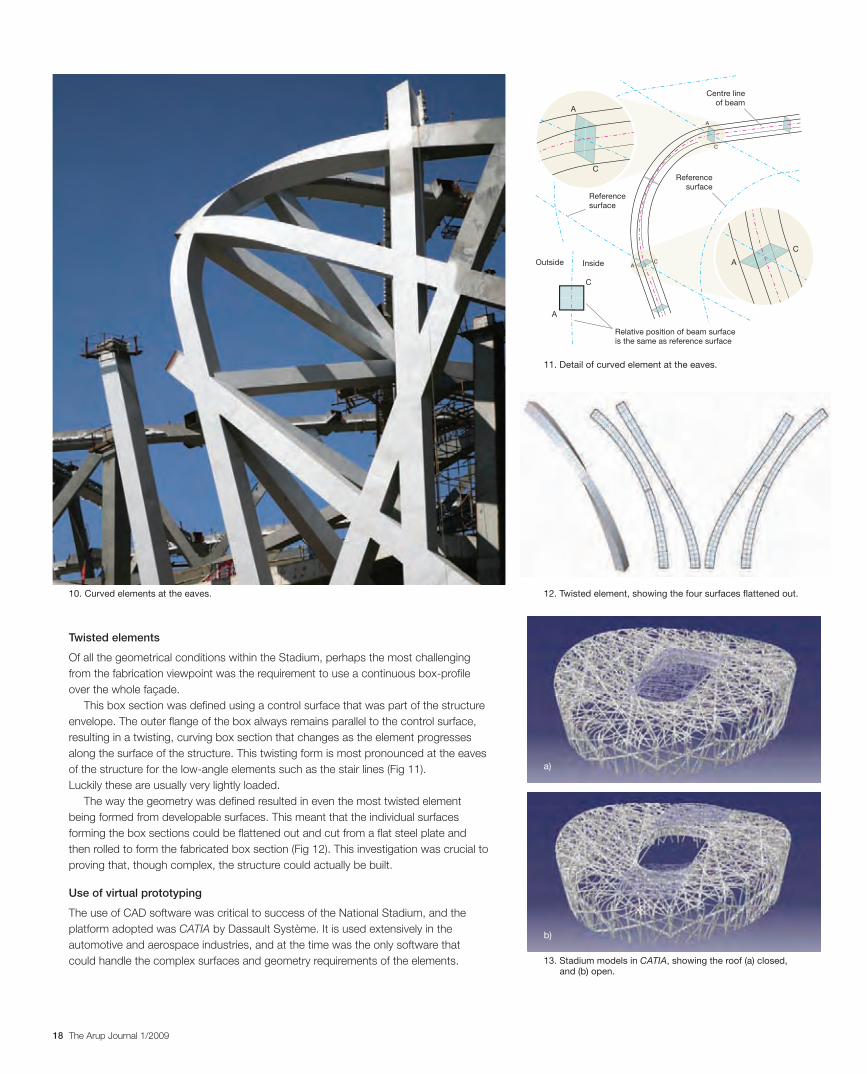
Of all the geometrical conditions within the Stadium, perhaps the most challenging from the fabrication viewpoint was the requirement to use a continuous box-profile over the whole façade.
This box section was defined using a control surface that was part of the structure envelope. The outer flange of the box always remains parallel to the control surface, resulting in a twisting, curving box section that changes as the element progresses along the surface of the structure. This twisting form is most pronounced at the eaves of the structure for the low-angle elements such as the stair lines (Fig 11). Luckily these are usually very lightly loaded.
The way the geometry was defined resulted in even the most twisted element being formed from developable surfaces. This meant that the individual surfaces forming the box sections could be flattened out and cut from a flat steel plate and then rolled to form the fabricated box section (Fig 12). This investigation was crucial to proving that, though complex, the structure could actually be built.
Use of virtual prototyping
The use of CAD software was critical to success of the National Stadium, and the platform adopted was CATIA by Dassault Système. It is used extensively in the automotive and aerospace industries, and at the time was the only software that could handle the complex surfaces and geometry requirements of the elements.
A
C
Reference
surface
Centre line
of beamA
C
A
InsideOutside
C
AC
A
C
Reference
surface
Relative position of beam surface
is the same as reference surface
11. Detail of curved element at the eaves.
12. Twisted element, showing the four surfaces flattened out.
13. Stadium models in CATIA, showing the roof (a) closed, and (b) open.
10. Curved elements at the eaves.
a)
b)
30223_Arup.indd 18 28/4/09 12:56:53
19The Arup Journal 1/2009
CATIA’s ability to deal with a vast number of components allowed the whole Stadium to be assembled in a single environment (Fig 13). The model contained all the structural elements, including the perimeter stairs, and the interactions between all the components were also managed in the same environment. This approach is called “virtual prototyping”4 as all elements can be assembled and tested in a virtual environment before commitment to building the physical reality.
CATIA is a parametric component-based modelling package. The advantage of using parametric software is significant when dealing with design that is required to be adjustable and continually changing like the Stadium. The basic premise is that instead of assigning rigid values to geometry such as length, angle, depth, etc, these can be assigned parameters that can be adjusted later. Because the software is also associative, relationships can be set between geometries that allow changes in parameters to be propagated through the model and downstream implications of changes assessed.
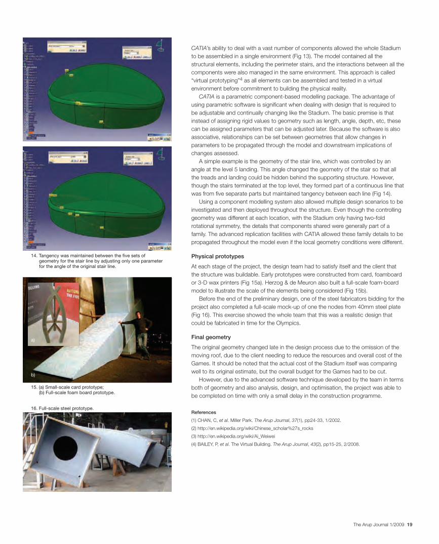
A simple example is the geometry of the stair line, which was controlled by an angle at the level 5 landing. This angle changed the geometry of the stair so that all the treads and landing could be hidden behind the supporting structure. However, though the stairs terminated at the top level, they formed part of a continuous line that was from five separate parts but maintained tangency between each line (Fig 14).
Using a component modelling system also allowed multiple design scenarios to be investigated and then deployed throughout the structure. Even though the controlling geometry was different at each location, with the Stadium only having two-fold rotational symmetry, the details that components shared were generally part of a family. The advanced replication facilities with CATIA allowed these family details to be propagated throughout the model even if the local geometry conditions were different.
Physical prototypes
At each stage of the project, the design team had to satisfy itself and the client that the structure was buildable. Early prototypes were constructed from card, foamboard or 3-D wax printers (Fig 15a). Herzog & de Meuron also built a full-scale foam-board model to illustrate the scale of the elements being considered (Fig 15b).
Before the end of the preliminary design, one of the steel fabricators bidding for the project also completed a full-scale mock-up of one the nodes from 40mm steel plate (Fig 16). This exercise showed the whole team that this was a realistic design that could be fabricated in time for the Olympics.
Final geometry
The original geometry changed late in the design process due to the omission of the moving roof, due to the client needing to reduce the resources and overall cost of the Games. It should be noted that the actual cost of the Stadium itself was comparing well to its original estimate, but the overall budget for the Games had to be cut.
However, due to the advanced software technique developed by the team in terms both of geometry and also analysis, design, and optimisation, the project was able to be completed on time with only a small delay in the construction programme.
References
(1) CHAN, C, et al. Miller Park. The Arup Journal, 37(1), pp24-33, 1/2002.
(2) http://en.wikipedia.org/wiki/Chinese_scholar%27s_rocks
(3) http://en.wikipedia.org/wiki/Ai_Weiwei
(4) BAILEY, P, et al. The Virtual Building. The Arup Journal, 43(2), pp15-25, 2/2008.
14. Tangency was maintained between the five sets of geometry for the stair line by adjusting only one parameter for the angle of the original stair line.
15. (a) Small-scale card prototype; (b) Full-scale foam board prototype.
16. Full-scale steel prototype.
a)
b)
30223_Arup.indd 19 28/4/09 12:56:58
20 The Arup Journal 1/2009
Original roof analysis model and results
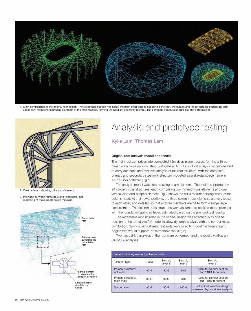
The main roof comprises interconnected 12m deep plane trusses, forming a three-dimensional truss network structural system. A 3-D structural analysis model was built to carry out static and dynamic analysis of the roof structure, with the complete primary and secondary steelwork structure modelled as a skeletal space frame in Arup’s GSA software (Fig 1).
The analysis model was created using beam elements. The roof is supported by 24 column truss structures, each comprising two inclined truss elements and one vertical diamond-shaped element. Fig 2 shows the truss member arrangement of the column head. At their lower portions, the three column truss elements are very close to each other, and detailed so that all three members merge to form a single large steel element. The column truss structures were assumed to be fixed to the pilecaps with the foundation spring stiffness estimated based on the pile load test results.
The retractable roof included in the original design was attached in its closed position to the top of this full model to allow dynamic analysis with the correct mass distribution. Springs with different restraints were used to model the bearings and bogies that would support the retractable roof (Fig 3).
Two basic GSA analyses of the roof were performed, and the results verified on SAP2000 analyses.
Analysis and prototype testingKylie Lam Thomas Lam
1. Main components of the original roof design: The retractable section (top right); the main steel trusses supporting the roof, the façade and the retractable section (far left); secondary members as bracing elements to the main trusses, forming the Stadium geometry (centre). The complete structural model is at the bottom right.
2. Column head, showing principal elements.
3. Interface between retractable and fixed roofs, and modelling of the support points restraint.
Table 1. Limiting element utilisation ratio.
Element type
Primary structure:columns
Primary structure:main truss
Secondaries
Static
80%
80%
90%
80%
80%
80%
90%
90%
100%
Seismiclevel 1
Seismiclevel 2
Seismiclevel 3
100% for slender sectionand 110% for others
100% for slender sectionand 110% for others
Not limited: member designassessed by non-linear analysis
Retractable roof
Primary truss suporting the retractable roof
Spring element to simulate the support condition
Link element to simulate the bogies
30223_Arup.indd 20 29/4/09 15:16:48
21The Arup Journal 1/2009
A static analysis under various combinations of dead, live, wind, snow, temperature, and seismic loading was carried out. The effects of pattern loading due to snow drifting and the effects of different positions of the retractable roof were evaluated separately. Dynamic analysis established the fundamental frequencies of vibration and mode shapes, and a modal analysis was also undertaken on the full 3-D analysis model.
Detailed seismic analyses were also performed to study the structural behaviour under a level 2 earthquake. In addition, the rare level 3 earthquake was studied to ensure that the roof would not collapse under this condition.
Member design check criteria and force/capacity utilisation ratio
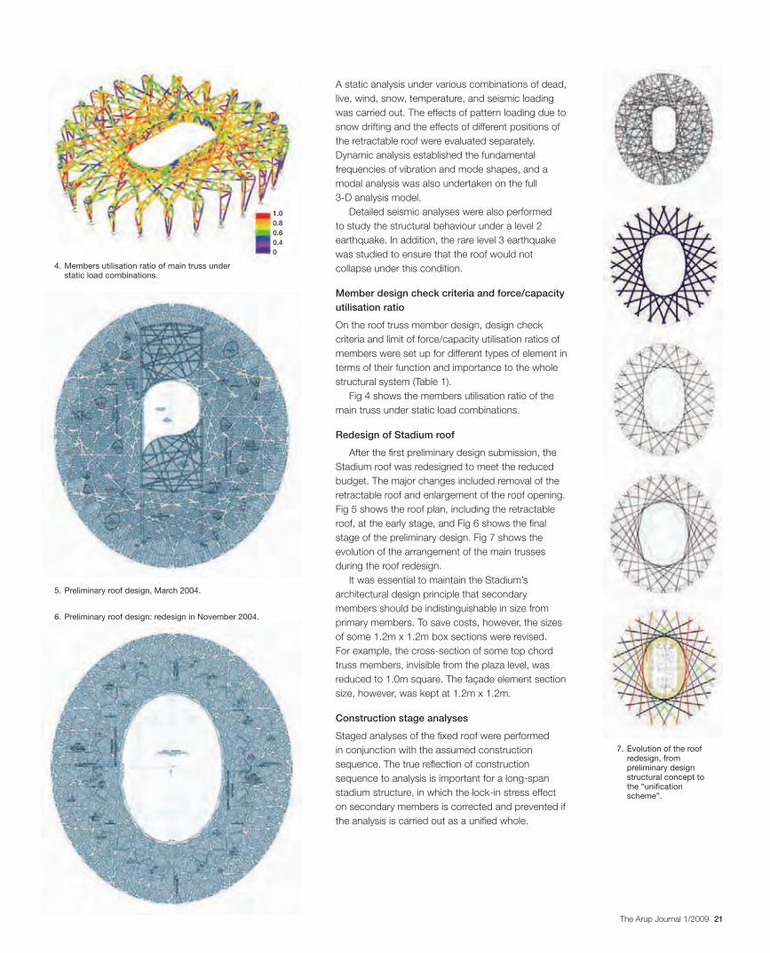
On the roof truss member design, design check criteria and limit of force/capacity utilisation ratios of members were set up for different types of element in terms of their function and importance to the whole structural system (Table 1).
Fig 4 shows the members utilisation ratio of the main truss under static load combinations.
Redesign of Stadium roof
After the first preliminary design submission, the Stadium roof was redesigned to meet the reduced budget. The major changes included removal of the retractable roof and enlargement of the roof opening. Fig 5 shows the roof plan, including the retractable roof, at the early stage, and Fig 6 shows the final stage of the preliminary design. Fig 7 shows the evolution of the arrangement of the main trusses during the roof redesign.
It was essential to maintain the Stadium’s architectural design principle that secondary members should be indistinguishable in size from primary members. To save costs, however, the sizes of some 1.2m x 1.2m box sections were revised. For example, the cross-section of some top chord truss members, invisible from the plaza level, was reduced to 1.0m square. The façade element section size, however, was kept at 1.2m x 1.2m.
Construction stage analyses
Staged analyses of the fixed roof were performed in conjunction with the assumed construction sequence. The true reflection of construction sequence to analysis is important for a long-span stadium structure, in which the lock-in stress effect on secondary members is corrected and prevented if the analysis is carried out as a unified whole.
4. Members utilisation ratio of main truss under static load combinations.
5. Preliminary roof design, March 2004.
6. Preliminary roof design: redesign in November 2004.
7. Evolution of the roof redesign, from preliminary design structural concept to the “unification scheme”.
1.00.80.60.40
30223_Arup.indd 21 28/4/09 12:57:09
22 The Arup Journal 1/2009
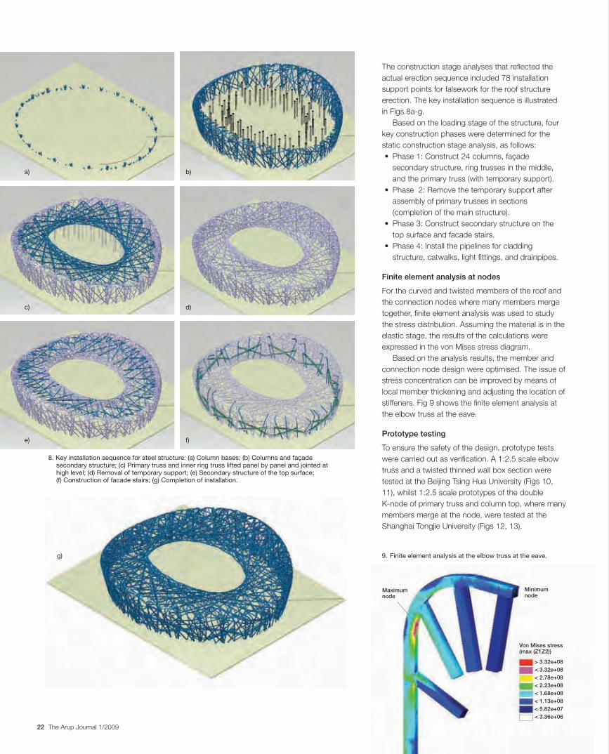
The construction stage analyses that reflected the actual erection sequence included 78 installation support points for falsework for the roof structure erection. The key installation sequence is illustrated in Figs 8a-g.
Based on the loading stage of the structure, four key construction phases were determined for the static construction stage analysis, as follows:• Phase1:Construct24columns,façade
secondary structure, ring trusses in the middle, and the primary truss (with temporary support).
• Phase2:Removethetemporarysupportafterassembly of primary trusses in sections (completion of the main structure).
• Phase3:Constructsecondarystructureonthetop surface and facade stairs.
• Phase4:Installthepipelinesforcladdingstructure, catwalks, light fittings, and drainpipes.
Finite element analysis at nodes
Forthecurvedandtwistedmembersoftheroofandthe connection nodes where many members merge together, finite element analysis was used to study the stress distribution. Assuming the material is in the elastic stage, the results of the calculations were expressedinthevonMisesstressdiagram.
Based on the analysis results, the member and connection node design were optimised. The issue of stressconcentrationcanbeimprovedbymeansoflocal member thickening and adjusting the location of stiffeners. Fig 9 shows the finite element analysis at theelbowtrussattheeave.
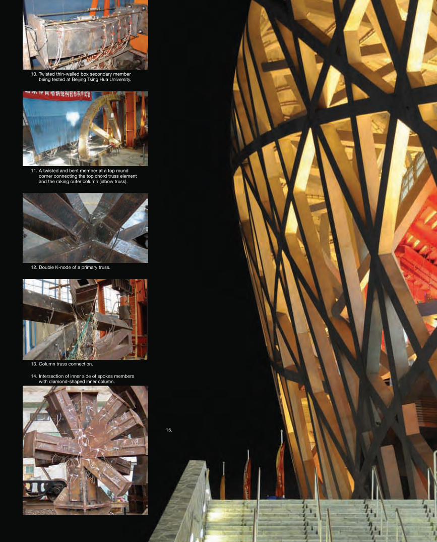
Prototype testing
To ensure the safety of the design, prototype tests werecarriedoutasverification.A1:2.5scaleelbowtruss and a twisted thinned wall box section were testedattheBeijingTsingHuaUniversity(Figs10,11),whilst1:2.5scaleprototypesofthedoubleK-node of primary truss and column top, where many members merge at the node, were tested at the ShanghaiTongjieUniversity(Figs12,13).
8. Key installation sequence for steel structure: (a) Column bases; (b) Columns and façade secondary structure; (c) Primary truss and inner ring truss lifted panel by panel and jointed at high level; (d) Removal of temporary support; (e) Secondary structure of the top surface; (f) Construction of facade stairs; (g) Completion of installation.
9. Finite element analysis at the elbow truss at the eave.
a)
e)
c)
b)
f)
g)
d)
Maximum node
Minimum node
Von Mises stress (max (Z1Z2))
> 3.32e+08< 3.32e+08< 2.78e+08< 2.23e+08< 1.68e+08< 1.13e+08< 5.82e+07< 3.36e+06
30223_Arup.indd 22 28/4/09 15:49:09
23The Arup Journal 1/2009
11. A twisted and bent member at a top round corner connecting the top chord truss element and the raking outer column (elbow truss).
12. Double K-node of a primary truss.
13. Column truss connection.
14. Intersection of inner side of spokes members with diamond-shaped inner column.
15.
10. Twisted thin-walled box secondary member being tested at Beijing Tsing Hua University.
30223_Arup.indd 23 28/4/09 12:57:34
24 The Arup Journal 1/2009
The challenge
The unique structural form, the architectural constraints, and the client’s and the Arup team’s desire to reduce the steel tonnage, all posed great challenges to the seismic design of the main roof of the “Bird’s Nest”.
The very long 313m span caused the seismic design to be significantly different in several ways from that of typical tall buildings. Seismic design measures that usually achieve the collapse prevention performance objective for tall buildings under the level 3 earthquake, for instance limiting inter-storey drifts and detailing for ductility, were insufficient for the “Bird’s Nest” roof structure. It could have collapsed straight downwards without lateral sway, due to damage to its gravity force-resisting system from vertical earthquake ground shaking alone.
The long span also causes the strength capacity of the primary truss members to be taken up primarily by gravity loads. The box section top chord and diagonal members in the primary trusses are subject to high axial compression forces under gravity loads, and will sustain damage and degrade in strength due to global as well as local buckling. They may not retain sufficient strength to prevent collapse when damaged by a level 3 earthquake.
Ductile detailing measures for the bracing members in special concentrically braced frames were thus insufficient to prevent collapse of the roof, because the bracing members in special concentrically braced frames of normal buildings are not part of the gravity force-resisting system. It was necessary to limit the post-buckling axial shortening of the top chords and the compression diagonals of the primary trusses, thereby limiting degradation of compressive strength. This, however, was beyond the conceptual framework of the conventional code prescriptive seismic design methodology.
A critical architectural constraint was the uniform 1.2m x 1.2m cross-section of the box section truss members. This is central to the architectural language of the “Bird’s Nest” – a seemingly arbitrary pattern that leaves spectators wondering which members are primary structures and which are secondary. To meet the limiting plate
Seismic design of the roofXiaonian Duan Goman Ho
width-to-thickness ratio (b/t) of 16 (16:1) and to achieve the seismically compact sections required by GB50011-2001, the minimum thickness needed to be approximately 70mm. Such a plate thickness would result in the use of unacceptably large amounts of steel, and lead to very high structural self-weight. This would further increase the gravity load on the structure as well as stiffening it, leading to even higher seismic forces. In addition to being uneconomical, using thicker steel plates would also have been less effective in achieving the collapse prevention performance objective for a level 3 earthquake.
From the structural design point of view, an effective and cost-efficient solution to reducing steel tonnage and thereby gravity loads – and meet the ductile detailing requirement of b/t ≤ 16 – would be to substantially reduce the outer dimension of the box section members in both primary and secondary trusses. It would be far easier to achieve seismically compact sections with much thinner plates, but due to the architectural constraints, this option was ruled out in the early stages.
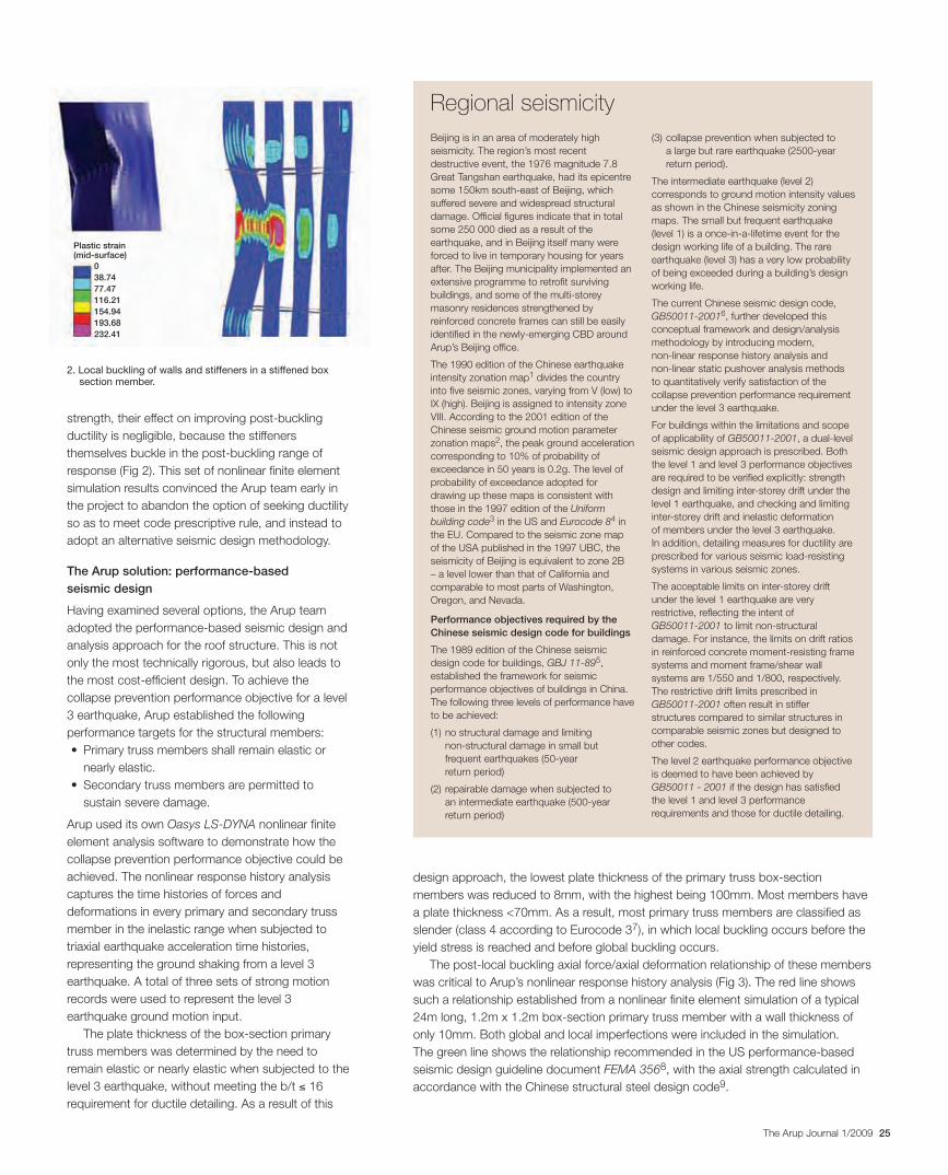
The behaviour of box section members with thin walls beyond the elastic limit is governed by their post-buckling behaviour. The Arup team investigated the effectiveness of welding longitudinal stiffeners and transverse diaphragms to the box section walls on improving the ductility capacity of these members. Nonlinear finite element simulations of the post-buckling behaviour of a typical member with a range of stiffener sizes and a range of diaphragm distances showed that, while the stiffeners and diaphragms are effective in postponing local buckling of the walls and thereby increasing member axial compressive
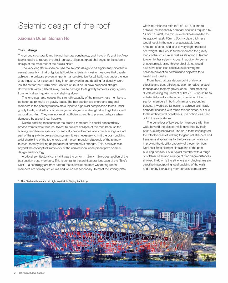
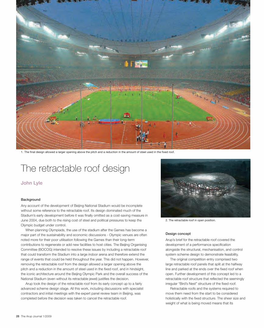
1. The Stadium illuminated at night against its Beijing backdrop.
30223_Arup.indd 24 28/4/09 12:57:37
25The Arup Journal 1/2009
strength, their effect on improving post-buckling ductility is negligible, because the stiffeners themselves buckle in the post-buckling range of response (Fig 2). This set of nonlinear finite element simulation results convinced the Arup team early in the project to abandon the option of seeking ductility so as to meet code prescriptive rule, and instead to adopt an alternative seismic design methodology.
The Arup solution: performance-based seismic design
Having examined several options, the Arup team adopted the performance-based seismic design and analysis approach for the roof structure. This is not only the most technically rigorous, but also leads to the most cost-efficient design. To achieve the collapse prevention performance objective for a level 3 earthquake, Arup established the following performance targets for the structural members:• Primarytrussmembersshallremainelasticor
nearly elastic.• Secondarytrussmembersarepermittedto
sustain severe damage.
Arup used its own Oasys LS-DYNA nonlinear finite element analysis software to demonstrate how the collapse prevention performance objective could be achieved. The nonlinear response history analysis captures the time histories of forces and deformations in every primary and secondary truss member in the inelastic range when subjected to triaxial earthquake acceleration time histories, representing the ground shaking from a level 3 earthquake. A total of three sets of strong motion records were used to represent the level 3 earthquake ground motion input.
The plate thickness of the box-section primary truss members was determined by the need to remain elastic or nearly elastic when subjected to the level 3 earthquake, without meeting the b/t ≤ 16 requirement for ductile detailing. As a result of this
Beijing is in an area of moderately high seismicity. The region’s most recent destructive event, the 1976 magnitude 7.8 Great Tangshan earthquake, had its epicentre some 150km south-east of Beijing, which suffered severe and widespread structural damage. Official figures indicate that in total some 250 000 died as a result of the earthquake, and in Beijing itself many were forced to live in temporary housing for years after. The Beijing municipality implemented an extensive programme to retrofit surviving buildings, and some of the multi-storey masonry residences strengthened by reinforced concrete frames can still be easily identified in the newly-emerging CBD around Arup’s Beijing office.
The 1990 edition of the Chinese earthquake intensity zonation map1 divides the country into five seismic zones, varying from V (low) to IX (high). Beijing is assigned to intensity zone VIII. According to the 2001 edition of the Chinese seismic ground motion parameter zonation maps2, the peak ground acceleration corresponding to 10% of probability of exceedance in 50 years is 0.2g. The level of probability of exceedance adopted for drawing up these maps is consistent with those in the 1997 edition of the Uniform building code3 in the US and Eurocode 84 in the EU. Compared to the seismic zone map of the USA published in the 1997 UBC, the seismicity of Beijing is equivalent to zone 2B – a level lower than that of California and comparable to most parts of Washington, Oregon, and Nevada.
Performance objectives required by the Chinese seismic design code for buildings
The 1989 edition of the Chinese seismic design code for buildings, GBJ 11-895, established the framework for seismic performance objectives of buildings in China. The following three levels of performance have to be achieved:
(1) no structural damage and limiting non-structural damage in small but frequent earthquakes (50-year return period)
(2) repairable damage when subjected to an intermediate earthquake (500-year return period)
(3) collapse prevention when subjected to a large but rare earthquake (2500-year return period).
The intermediate earthquake (level 2) corresponds to ground motion intensity values as shown in the Chinese seismicity zoning maps. The small but frequent earthquake (level 1) is a once-in-a-lifetime event for the design working life of a building. The rare earthquake (level 3) has a very low probability of being exceeded during a building’s design working life.
The current Chinese seismic design code, GB50011-20016, further developed this conceptual framework and design/analysis methodology by introducing modern, non-linear response history analysis and non-linear static pushover analysis methods to quantitatively verify satisfaction of the collapse prevention performance requirement under the level 3 earthquake.
For buildings within the limitations and scope of applicability of GB50011-2001, a dual-level seismic design approach is prescribed. Both the level 1 and level 3 performance objectives are required to be verified explicitly: strength design and limiting inter-storey drift under the level 1 earthquake, and checking and limiting inter-storey drift and inelastic deformation of members under the level 3 earthquake. In addition, detailing measures for ductility are prescribed for various seismic load-resisting systems in various seismic zones.
The acceptable limits on inter-storey drift under the level 1 earthquake are very restrictive, reflecting the intent of GB50011-2001 to limit non-structural damage. For instance, the limits on drift ratios in reinforced concrete moment-resisting frame systems and moment frame/shear wall systems are 1/550 and 1/800, respectively. The restrictive drift limits prescribed in GB50011-2001 often result in stiffer structures compared to similar structures in comparable seismic zones but designed to other codes.
The level 2 earthquake performance objective is deemed to have been achieved by GB50011 - 2001 if the design has satisfied the level 1 and level 3 performance requirements and those for ductile detailing.
Regional seismicity
design approach, the lowest plate thickness of the primary truss box-section members was reduced to 8mm, with the highest being 100mm. Most members have a plate thickness <70mm. As a result, most primary truss members are classified as slender (class 4 according to Eurocode 37), in which local buckling occurs before the yield stress is reached and before global buckling occurs.
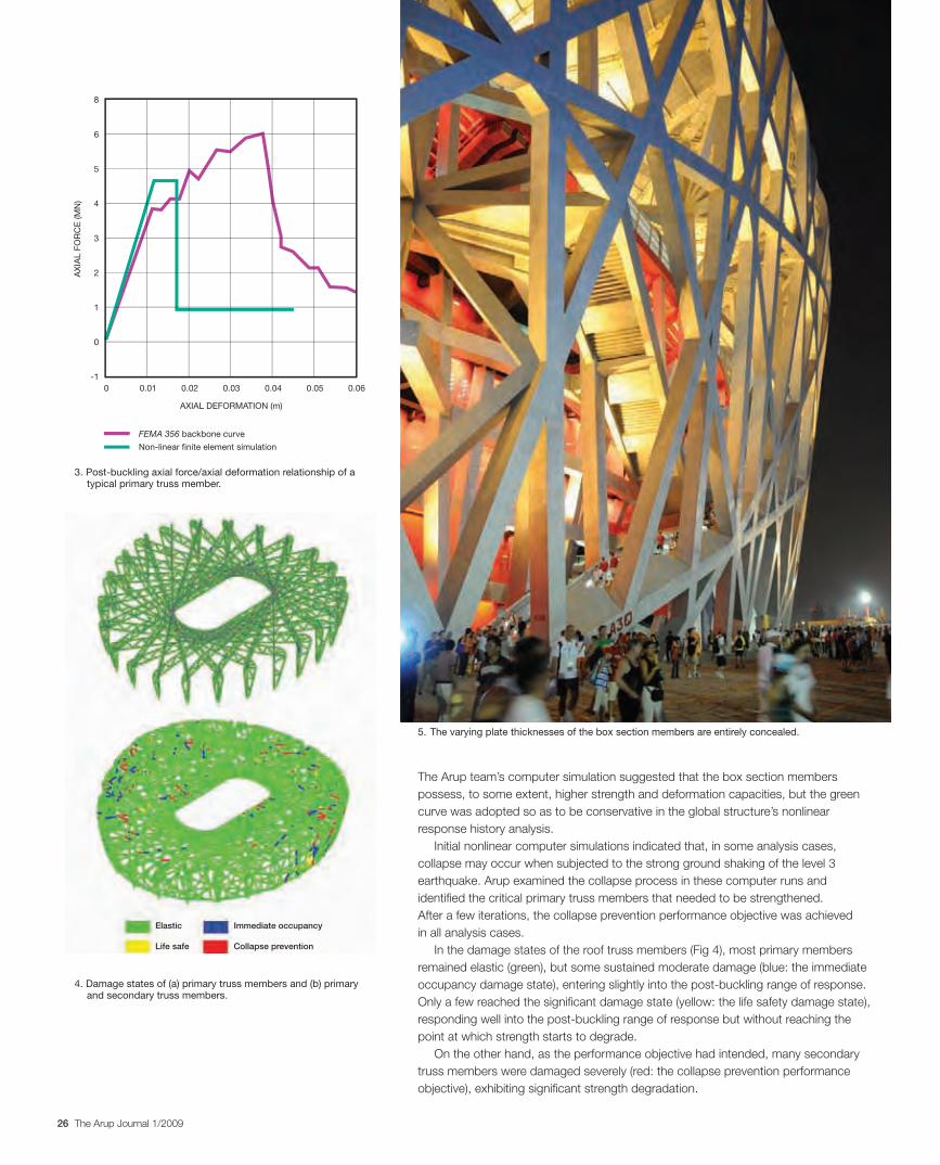
The post-local buckling axial force/axial deformation relationship of these members was critical to Arup’s nonlinear response history analysis (Fig 3). The red line shows such a relationship established from a nonlinear finite element simulation of a typical 24m long, 1.2m x 1.2m box-section primary truss member with a wall thickness of only 10mm. Both global and local imperfections were included in the simulation. The green line shows the relationship recommended in the US performance-based seismic design guideline document FEMA 3568, with the axial strength calculated in accordance with the Chinese structural steel design code9.
038.7477.47116.21154.94193.68232.41
Plastic strain (mid-surface)
2. Local buckling of walls and stiffeners in a stiffened box section member.
30223_Arup.indd 25 28/4/09 12:57:39
26 The Arup Journal 1/2009
AXIAL DEFORMATION (m)
FEMA 356 backbone curve
Non-linear finite element simulation
0.060.050.040.030.020.010
AX
IAL
FO
RC
E (M
N)
8
6
5
4
3
2
1
0
-1
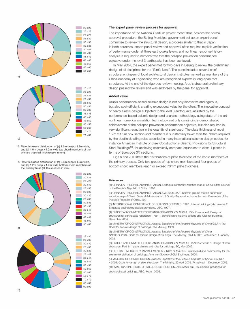
4. Damage states of (a) primary truss members and (b) primary and secondary truss members.
5. The varying plate thicknesses of the box section members are entirely concealed.
3. Post-buckling axial force/axial deformation relationship of a typical primary truss member.
The Arup team’s computer simulation suggested that the box section members possess, to some extent, higher strength and deformation capacities, but the green curve was adopted so as to be conservative in the global structure’s nonlinear response history analysis.
Initial nonlinear computer simulations indicated that, in some analysis cases, collapse may occur when subjected to the strong ground shaking of the level 3 earthquake. Arup examined the collapse process in these computer runs and identified the critical primary truss members that needed to be strengthened. After a few iterations, the collapse prevention performance objective was achieved in all analysis cases.
In the damage states of the roof truss members (Fig 4), most primary members remained elastic (green), but some sustained moderate damage (blue: the immediate occupancy damage state), entering slightly into the post-buckling range of response. Only a few reached the significant damage state (yellow: the life safety damage state), responding well into the post-buckling range of response but without reaching the point at which strength starts to degrade.
On the other hand, as the performance objective had intended, many secondary truss members were damaged severely (red: the collapse prevention performance objective), exhibiting significant strength degradation.
Elastic Immediate occupancy
Life safe Collapse prevention
30223_Arup.indd 26 28/4/09 12:57:44
27The Arup Journal 1/2009
The expert panel review process for approval
The importance of the National Stadium project meant that, besides the normal approval procedure, the Beijing Municipal government set up an expert panel committee to review the structural design, a process similar to that in Japan. In both countries, expert panel review and approval often requires explicit verification of performance under all three earthquake levels, and nonlinear response history analysis is required to demonstrate that the collapse prevention performance objective under the level 3 earthquake has been achieved.
In May 2004, the expert panel met for two days in Beijing to review the preliminary design of all disciplines for the “Bird’s Nest”. The panel included several chief structural engineers of local architectural design institutes, as well as members of the China Academy of Engineering who are recognised experts in long-span roof structures. At the end of the rigorous review meeting, Arup’s structural preliminary design passed the review and was endorsed by the panel for approval.
Added value
Arup’s performance-based seismic design is not only innovative and rigorous, but also cost-efficient, creating exceptional value for the client. The innovative concept of nearly elastic design subjected to the level 3 earthquake, assisted by the performance-based seismic design and analysis methodology using state-of-the-art nonlinear numerical simulation technology, not only convincingly demonstrated achievement of the collapse prevention performance objective, but also resulted in very significant reduction in the quantity of steel used. The plate thickness of most 1.2m x 1.2m box-section roof members is substantially lower than the 70mm required by the ductile detailing rules specified in many international seismic design codes, for instance American Institute of Steel Construction’s Seismic Provisions for Structural Steel Buildings10, for achieving seismically compact (equivalent to class 1 plastic in terms of Eurocode 37) sections.
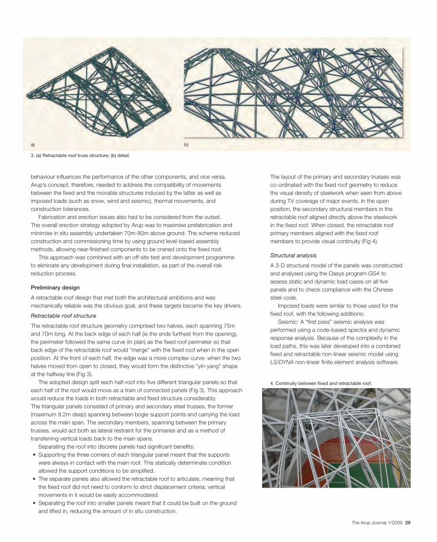
Figs 6 and 7 illustrate the distributions of plate thickness of the chord members of the primary trusses. Only two groups of top chord members and four groups of bottom chord members reach or exceed 70mm plate thickness.
References
(1) CHINA EARTHQUAKE ADMINISTRATION. Earthquake intensity zonation map of China. State Council of the People’s Republic of China, 1990.
(2) CHINA EARTHQUAKE ADMINISTRATION. GB18306-2001: Seismic ground motion parameter zonation map of China. General Administration of Quality Supervision, Inspection and Quarantine of the People’s Republic of China, 2001.
(3) INTERNATIONAL CONFERENCE OF BUILDING OFFICIALS. 1997 Uniform building code. Volume 2: Structural engineering design provisions. UBC, 1997.
(4) EUROPEAN COMMITTEE FOR STANDARDIZATION, EN 1998-1: 2004/Eurocode 8: Design of structures for earthquake resistance – Part 1: general rules, seismic actions and rules for buildings, December 2004.
(5) MINISTRY OF CONSTRUCTION. National Standard of the People’s Republic of China GBJ 11-89. Code for seismic design of buildings. The Ministry, 1989.
(6) MINISTRY OF CONSTRUCTION. National Standard of the People’s Republic of China GB50011-2001. Code for seismic design of buildings. The Ministry, 20 July 2001. Actualised: 1 January 2002.
(7) EUROPEAN COMMITTEE FOR STANDARDIZATION. EN 1993-1-1: 2005/Eurocode 3. Design of steel structures. Part 1-1: general rules and rules for buildings. EC, May 2005.
(8) FEDERAL EMERGENCY MANAGEMENT AGENCY. FEMA 356. Prestandard and commentary for the seismic rehabilitation of buildings. American Society of Civil Engineers, 2000.
(9) MINISTRY OF CONSTRUCTION. National Standard of the People’s Republic of China GB50017 – 2003. Code for design of steel structures. The Ministry, 25 April 2003. Actualised: 1 December 2003.
(10) AMERICAN INSTITUTE OF STEEL CONSTRUCTION. AISC/ANSI 341–05. Seismic provisions for
structural steel buildings. AISC, March 2005.
20 x 20
20 x 25
25 x 25
25 x 30
30 x 30
30 x 36
30 x 42
36 x 36
36 x 42
42 x 42
42 x 50
50 x 60
60 x 60
20 x 20
20 x 25
25 x 25
20 x 30
25 x 30
20 x 36
30 x 30
25 x 36
30 x 36
36 x 36
30 x 42
36 x 42
42 x 42
42 x 50
50 x 60
25 x 30
20 x 36
30 x 30
25 x 36
30 x 36
25 x 42
30 x 42
36 x 42
30 x 50
50 x 50
50 x 60
50 x 70
70 x 70
80 x 80
90 x 90
20 x 20
20 x 25
25 x 25
20 x 30
25 x 30
30 x 30
30 x 36
36 x 36
42 x 42
42 x 50
50 x 50
60 x 60
70 x 70
70 x 80
6. Plate thickness distribution of (a) 1.2m deep x 1.2m wide, and (b) 1.0m deep x 1.2m wide top chord members of the primary truss (all thicknesses in mm).
7. Plate thickness distribution of (a) 0.8m deep x 1.2m wide, and (b) 1.2m deep x 1.2m wide bottom chord members of the primary truss (all thicknesses in mm).
a)
a)
b)
b)
30223_Arup.indd 27 28/4/09 12:57:45
28 The Arup Journal 1/2009
The retractable roof designJohn Lyle
2. The retractable roof in open position.
1. The final design allowed a larger opening above the pitch and a reduction in the amount of steel used in the fixed roof.
Design concept
Arup’s brief for the retractable roof covered the development of a performance specification alongside the structural, mechanisation, and control system scheme design to demonstrate feasibility.
The original competition entry comprised two large retractable roof panels that split at the halfway line and parked at the ends over the fixed roof when open. Further development of this concept led to a retractable roof structure that reflected the seemingly irregular “Bird’s Nest” structure of the fixed roof.
Retractable roofs and the systems required to move them need from the start to be considered holistically with the fixed structure. The sheer size and weight of what is being moved means that its
Background
Any account of the development of Beijing National Stadium would be incomplete without some reference to the retractable roof. Its design dominated much of the Stadium’s early development before it was finally omitted as a cost-saving measure in June 2004, due both to the rising cost of steel and political pressures to keep the Olympic budget under control.
When planning Olympiads, the use of the stadium after the Games has become a major part of the sustainability and economic discussions - Olympic venues are often noted more for their poor utilisation following the Games than their long-term contributions to regenerate or add new facilities to host cities. The Beijing Organising Committee (BOCOG) intended to resolve these issues by including a retractable roof that could transform the Stadium into a large indoor arena and therefore extend the range of events that could be held throughout the year. This did not happen. However, removing the retractable roof from the design allowed a larger opening above the pitch and a reduction in the amount of steel used in the fixed roof, and in hindsight, the iconic architecture around the Beijing Olympic Park and the overall success of the National Stadium (even without its retractable jewel) justifies the decision.
Arup took the design of the retractable roof from its early concept up to a fairly advanced scheme design stage. All this work, including discussions with specialist contractors and initial meetings with the expert panel review team in Beijing, was completed before the decision was taken to cancel the retractable roof.
30223_Arup.indd 28 28/4/09 12:57:52
29The Arup Journal 1/2009
behaviour influences the performance of the other components, and vice versa. Arup’s concept, therefore, needed to address the compatibility of movements between the fixed and the movable structures induced by the latter as well as imposed loads (such as snow, wind and seismic), thermal movements, and construction tolerances.
Fabrication and erection issues also had to be considered from the outset. The overall erection strategy adopted by Arup was to maximise prefabrication and minimise in situ assembly undertaken 70m-80m above ground. The scheme reduced construction and commissioning time by using ground level-based assembly methods, allowing near-finished components to be craned onto the fixed roof.
This approach was combined with an off-site test and development programme to eliminate any development during final installation, as part of the overall risk reduction process.
Preliminary design
A retractable roof design that met both the architectural ambitions and was mechanically reliable was the obvious goal, and these targets became the key drivers.
Retractable roof structure
The retractable roof structure geometry comprised two halves, each spanning 75m and 70m long. At the back edge of each half (ie the ends furthest from the opening), the perimeter followed the same curve (in plan) as the fixed roof perimeter so that back edge of the retractable roof would “merge” with the fixed roof when in the open position. At the front of each half, the edge was a more complex curve: when the two halves moved from open to closed, they would form the distinctive “yin-yang” shape at the halfway line (Fig 3).
The adopted design split each half-roof into five different triangular panels so that each half of the roof would move as a train of connected panels (Fig 3). This approach would reduce the loads in both retractable and fixed structure considerably. The triangular panels consisted of primary and secondary steel trusses, the former (maximum 8.2m deep) spanning between bogie support points and carrying the load across the main span. The secondary members, spanning between the primary trusses, would act both as lateral restraint for the primaries and as a method of transferring vertical loads back to the main spans.
Separating the roof into discrete panels had significant benefits:• Supportingthethreecornersofeachtriangularpanelmeantthatthesupports
were always in contact with the main roof. This statically determinate condition allowed the support conditions to be simplified.
• Theseparatepanelsalsoallowedtheretractablerooftoarticulate,meaningthatthe fixed roof did not need to conform to strict displacement criteria; vertical movements in it would be easily accommodated.
• Separatingtheroofintosmallerpanelsmeantthatitcouldbebuiltonthegroundand lifted in, reducing the amount of in situ construction.
The layout of the primary and secondary trusses was co-ordinated with the fixed roof geometry to reduce the visual density of steelwork when seen from above during TV coverage of major events. In the open position, the secondary structural members in the retractable roof aligned directly above the steelwork in the fixed roof. When closed, the retractable roof primary members aligned with the fixed roof members to provide visual continuity (Fig 4).
Structural analysis
A 3-D structural model of the panels was constructed and analysed using the Oasys program GSA to assess static and dynamic load cases on all five panels and to check compliance with the Chinese steel code.
Imposed loads were similar to those used for the fixed roof, with the following additions:
Seismic: A “first pass” seismic analysis was performed using a code-based spectra and dynamic response analysis. Because of the complexity in the load paths, this was later developed into a combined fixed and retractable non-linear seismic model using LS/DYNA non-linear finite element analysis software.
3. (a) Retractable roof truss structure; (b) detail.
4. Continuity between fixed and retractable roof.
a) b)
30223_Arup.indd 29 28/4/09 12:57:54
30 The Arup Journal 1/2009
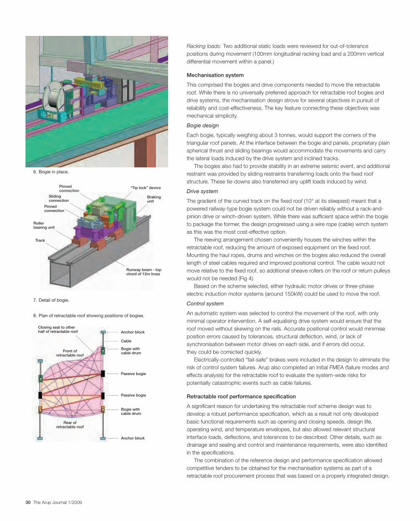
Racking loads: Two additional static loads were reviewed for out-of-tolerance positions during movement (100mm longitudinal racking load and a 200mm vertical differential movement within a panel.)
Mechanisation system
This comprised the bogies and drive components needed to move the retractable roof. While there is no universally preferred approach for retractable roof bogies and drive systems, the mechanisation design strove for several objectives in pursuit of reliability and cost-effectiveness. The key feature connecting these objectives was mechanical simplicity.
Bogie design
Each bogie, typically weighing about 3 tonnes, would support the corners of the triangular roof panels. At the interface between the bogie and panels, proprietary plain spherical thrust and sliding bearings would accommodate the movements and carry the lateral loads induced by the drive system and inclined tracks.
The bogies also had to provide stability in an extreme seismic event, and additional restraint was provided by sliding restraints transferring loads onto the fixed roof structure. These tie-downs also transferred any uplift loads induced by wind.
Drive system
The gradient of the curved track on the fixed roof (10° at its steepest) meant that a powered railway-type bogie system could not be driven reliably without a rack-and-pinion drive or winch-driven system. While there was sufficient space within the bogie to package the former, the design progressed using a wire rope (cable) winch system as this was the most cost-effective option.
The reeving arrangement chosen conveniently houses the winches within the retractable roof, reducing the amount of exposed equipment on the fixed roof. Mounting the haul ropes, drums and winches on the bogies also reduced the overall length of steel cables required and improved positional control. The cable would not move relative to the fixed roof, so additional sheave rollers on the roof or return pulleys would not be needed (Fig 4).
Based on the scheme selected, either hydraulic motor drives or three-phase electric induction motor systems (around 150kW) could be used to move the roof.
Control system
An automatic system was selected to control the movement of the roof, with only minimal operator intervention. A self-equalising drive system would ensure that the roof moved without skewing on the rails. Accurate positional control would minimise position errors caused by tolerances, structural deflection, wind, or lack of synchronisation between motor drives on each side, and if errors did occur, they could be corrected quickly.
Electrically-controlled “fail-safe” brakes were included in the design to eliminate the risk of control system failures. Arup also completed an initial FMEA (failure modes and effects analysis) for the retractable roof to evaluate the system-wide risks for potentially catastrophic events such as cable failures.
Retractable roof performance specification
A significant reason for undertaking the retractable roof scheme design was to develop a robust performance specification, which as a result not only developed basic functional requirements such as opening and closing speeds, design life, operating wind, and temperature envelopes, but also allowed relevant structural interface loads, deflections, and tolerances to be described. Other details, such as drainage and sealing and control and maintenance requirements, were also identified in the specifications.
The combination of the reference design and performance specification allowed competitive tenders to be obtained for the mechanisation systems as part of a retractable roof procurement process that was based on a properly integrated design.
8. Plan of retractable roof showing positions of bogies.
Closing seal to other half of retractable roof Anchor block
Track
Roller bearing unit
Sliding connection
Pinned connection
Pinned connection
“Tip lock” device
Braking unit
Runway beam - top chord of 12m truss
Anchor block
Bogie with cable drum
Cable
Passive bogie
Passive bogie
Bogie with cable drum
Front of retractable roof
Rear of retractable roof
6. Bogie in place.
7. Detail of bogie.
30223_Arup.indd 30 28/4/09 12:58:03
31The Arup Journal 1/2009
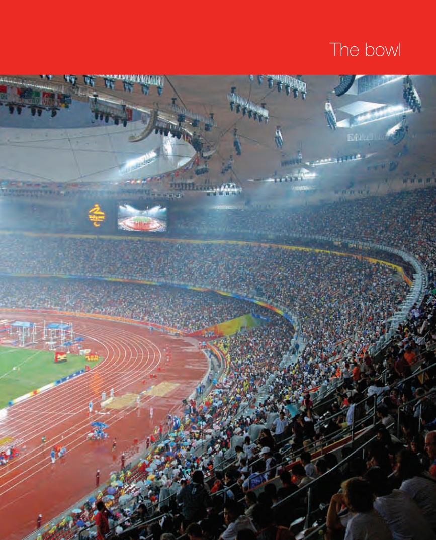
The bowl
30223_Arup.indd 31 28/4/09 12:58:08
32 The Arup Journal 1/2009
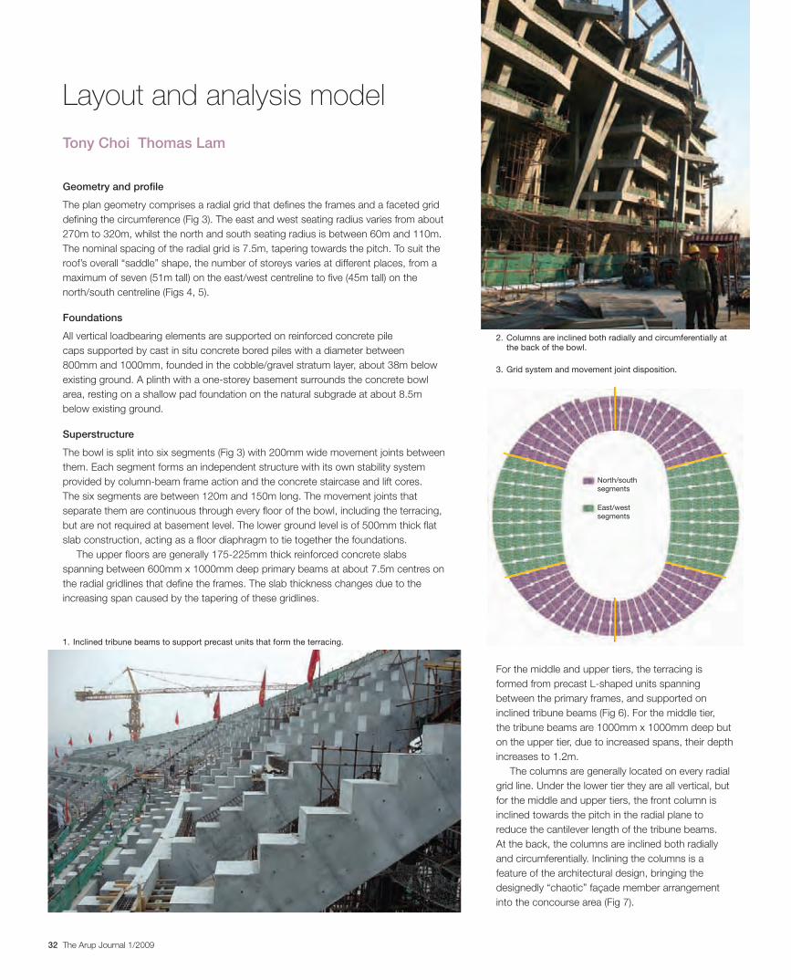
Geometry and profile
The plan geometry comprises a radial grid that defines the frames and a faceted grid defining the circumference (Fig 3). The east and west seating radius varies from about 270m to 320m, whilst the north and south seating radius is between 60m and 110m. The nominal spacing of the radial grid is 7.5m, tapering towards the pitch. To suit the roof’s overall “saddle” shape, the number of storeys varies at different places, from a maximum of seven (51m tall) on the east/west centreline to five (45m tall) on the north/south centreline (Figs 4, 5).
Foundations
All vertical loadbearing elements are supported on reinforced concrete pile caps supported by cast in situ concrete bored piles with a diameter between 800mm and 1000mm, founded in the cobble/gravel stratum layer, about 38m below existing ground. A plinth with a one-storey basement surrounds the concrete bowl area, resting on a shallow pad foundation on the natural subgrade at about 8.5m below existing ground.
Superstructure
The bowl is split into six segments (Fig 3) with 200mm wide movement joints between them. Each segment forms an independent structure with its own stability system provided by column-beam frame action and the concrete staircase and lift cores. The six segments are between 120m and 150m long. The movement joints that separate them are continuous through every floor of the bowl, including the terracing, but are not required at basement level. The lower ground level is of 500mm thick flat slab construction, acting as a floor diaphragm to tie together the foundations.
The upper floors are generally 175-225mm thick reinforced concrete slabs spanning between 600mm x 1000mm deep primary beams at about 7.5m centres on the radial gridlines that define the frames. The slab thickness changes due to the increasing span caused by the tapering of these gridlines.
Layout and analysis model
For the middle and upper tiers, the terracing is formed from precast L-shaped units spanning between the primary frames, and supported on inclined tribune beams (Fig 6). For the middle tier, the tribune beams are 1000mm x 1000mm deep but on the upper tier, due to increased spans, their depth increases to 1.2m.
The columns are generally located on every radial grid line. Under the lower tier they are all vertical, but for the middle and upper tiers, the front column is inclined towards the pitch in the radial plane to reduce the cantilever length of the tribune beams. At the back, the columns are inclined both radially and circumferentially. Inclining the columns is a feature of the architectural design, bringing the designedly “chaotic” façade member arrangement into the concourse area (Fig 7).
Tony Choi Thomas Lam
1. Inclined tribune beams to support precast units that form the terracing.
North/southsegments
East/westsegments
3. Grid system and movement joint disposition.
2. Columns are inclined both radially and circumferentially at the back of the bowl.
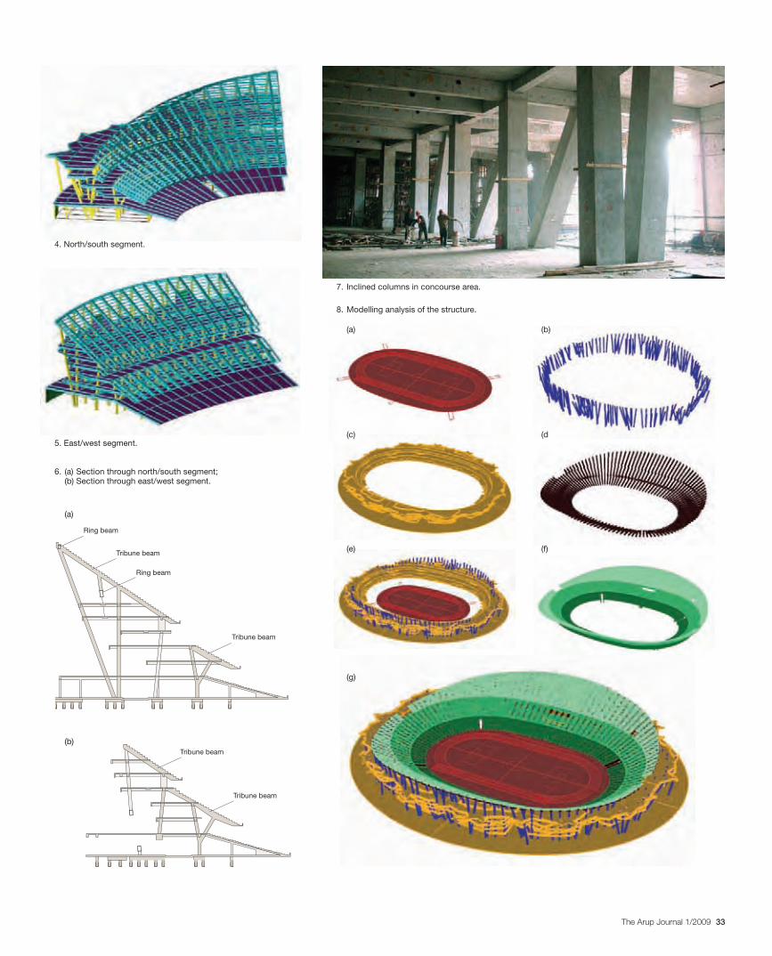
33The Arup Journal 1/2009
Ring beam
Tribune beam
Tribune beam
Ring beam
Tribune beam
Tribune beam
7. Inclined columns in concourse area.
5. East/west segment.
6. (a) Section through north/south segment; (b) Section through east/west segment.
(a)
(a)
(c)
(e)
(g)
(b)
(d
(f)
(b)
8. Modelling analysis of the structure.
4. North/south segment.
30223_Arup.indd 33 29/4/09 15:10:19
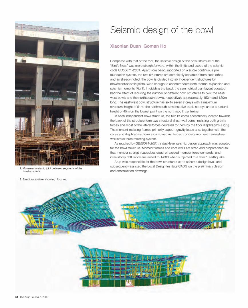
34 The Arup Journal 1/2009
Compared with that of the roof, the seismic design of the bowl structure of the “Bird’s Nest” was more straightforward, within the limits and scope of the seismic code GB50011-2001. Apart from being supported on a single continuous pile foundation system, the two structures are completely separated from each other, and as already noted, the bowl is divided into six independent structures by movement/seismic joints, wide enough to accommodate both thermal expansion and seismic moments (Fig 1). In dividing the bowl, the symmetrical plan layout adopted had the effect of reducing the number of different bowl structures to two: the east\west bowls and the north\south bowls, respectively approximately 150m and 120m long. The east\west bowl structure has six to seven storeys with a maximum structural height of 51m; the north\south bowl has five to six storeys and a structural height of 45m on the lowest point on the north/south centreline.
In each independent bowl structure, the two lift cores eccentrically located towards the back of the structure form two structural shear wall cores, resisting both gravity forces and most of the lateral forces delivered to them by the floor diaphragms (Fig 2). The moment-resisting frames primarily support gravity loads and, together with the cores and diaphragms, form a combined reinforced concrete moment frame\shear wall lateral force resisting system.
As required by GB50011-2001, a dual-level seismic design approach was adopted for the bowl structure. Moment frames and core walls are sized and proportioned so that member strength capacities equal or exceed member force demands, and inter-storey drift ratios are limited to 1/800 when subjected to a level 1 earthquake.
Arup was responsible for the bowl structures up to scheme design level, and subsequently assisted the Local Design Institute CADG on the preliminary design and construction drawings.
Seismic design of the bowl
Xiaonian Duan Goman Ho
2. Structural system, showing lift cores.
1. Movement/seismic joint between segments of the bowl structure.
30223_Arup.indd 34 28/4/09 12:58:35
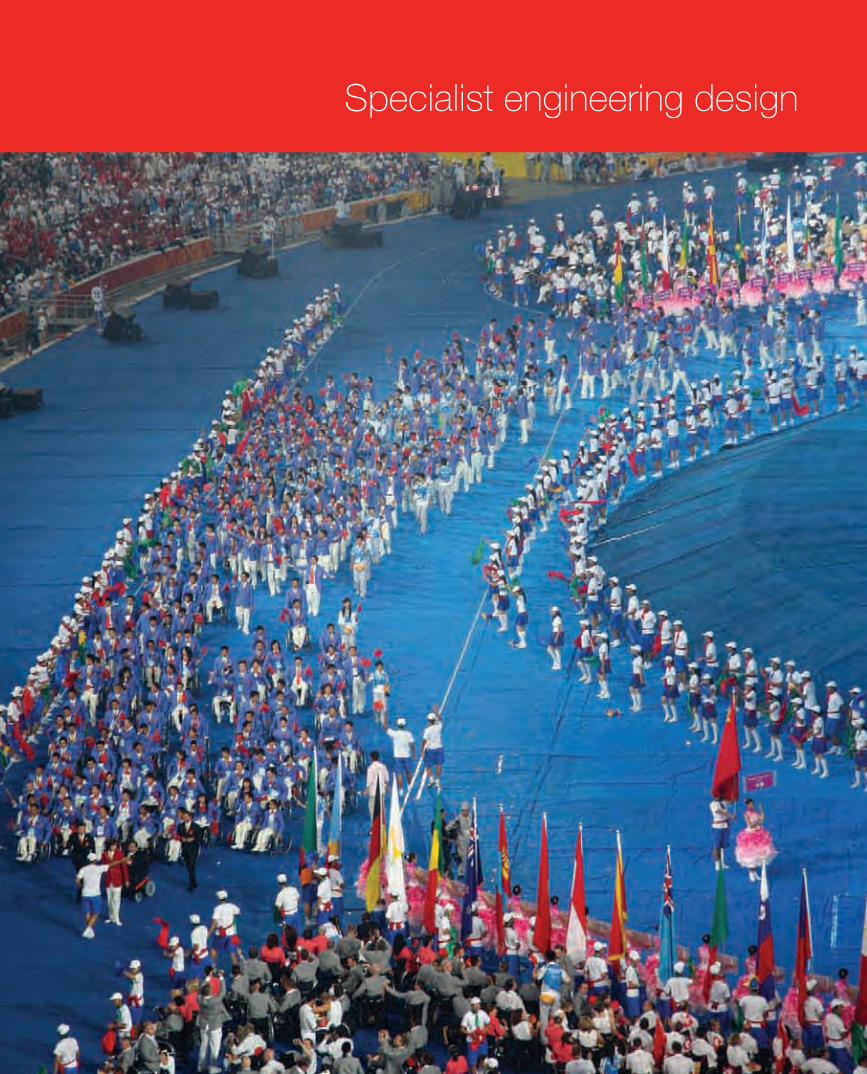
35The Arup Journal 1/2009
Specialist engineering design
30223_Arup.indd 35 28/4/09 12:58:42
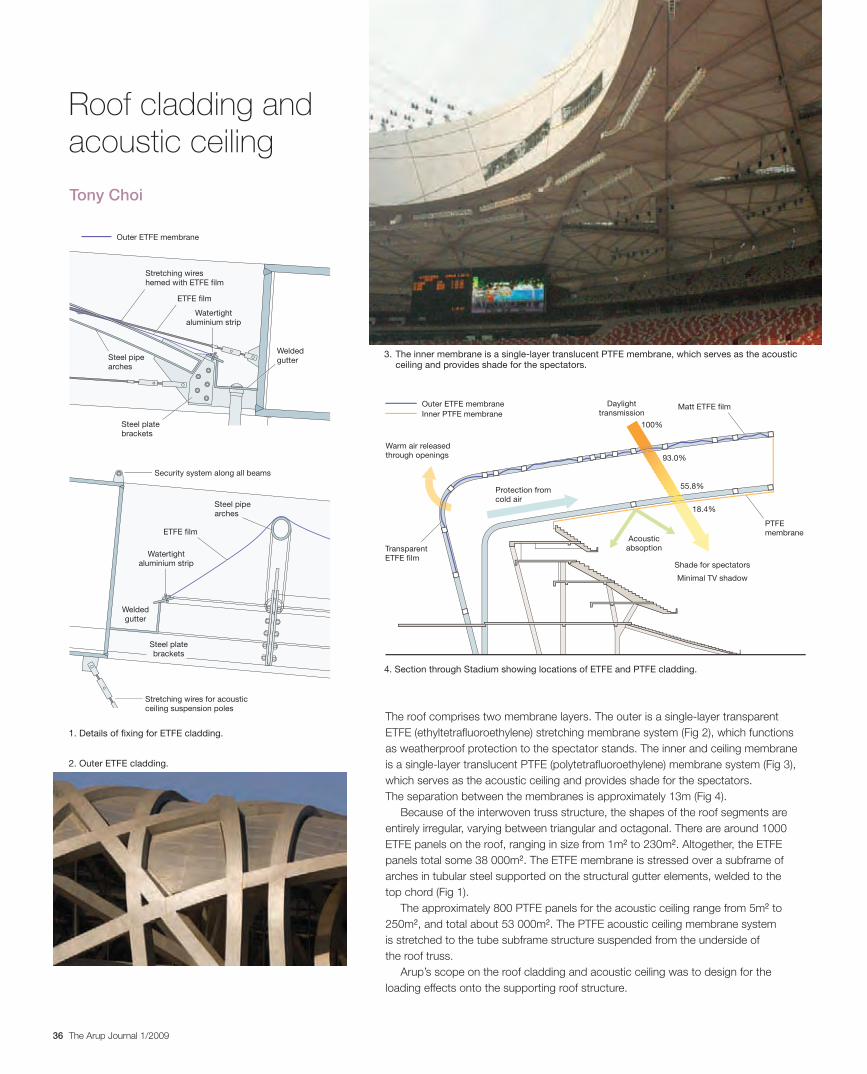
36 The Arup Journal 1/2009
The roof comprises two membrane layers. The outer is a single-layer transparent
ETFE (ethyltetrafluoroethylene) stretching membrane system (Fig 2), which functions
as weatherproof protection to the spectator stands. The inner and ceiling membrane
is a single-layer translucent PTFE (polytetrafluoroethylene) membrane system (Fig 3),
which serves as the acoustic ceiling and provides shade for the spectators.
The separation between the membranes is approximately 13m (Fig 4).
Because of the interwoven truss structure, the shapes of the roof segments are
entirely irregular, varying between triangular and octagonal. There are around 1000
ETFE panels on the roof, ranging in size from 1m2 to 230m2. Altogether, the ETFE
panels total some 38 000m2. The ETFE membrane is stressed over a subframe of
arches in tubular steel supported on the structural gutter elements, welded to the
top chord (Fig 1).
The approximately 800 PTFE panels for the acoustic ceiling range from 5m2 to
250m2, and total about 53 000m2. The PTFE acoustic ceiling membrane system
is stretched to the tube subframe structure suspended from the underside of
the roof truss.
Arup’s scope on the roof cladding and acoustic ceiling was to design for the
loading effects onto the supporting roof structure.
Tony Choi
Roof cladding and acoustic ceiling
Shade for spectators
Minimal TV shadow
Matt ETFE film
Protection from
cold air
Warm air released
through openings
Outer ETFE membrane
Inner PTFE membrane
PTFE
membraneAcoustic
absoption
100%
Daylight
transmission
93.0%
55.8%
18.4%
Transparent
ETFE film
Outer ETFE membrane
Stretching wires
hemed with ETFE film
ETFE film
ETFE film
Welded
gutter
Welded
gutter
Steel pipe
arches
Steel pipe
arches
Steel plate
brackets
Steel plate
brackets
Stretching wires for acoustic
ceiling suspension poles
Watertight
aluminium strip
Watertight
aluminium strip
Security system along all beams
1. Details of fixing for ETFE cladding.
4. Section through Stadium showing locations of ETFE and PTFE cladding.
3. The inner membrane is a single-layer translucent PTFE membrane, which serves as the acoustic ceiling and provides shade for the spectators.
2. Outer ETFE cladding.
30223_Arup.indd 36 28/4/09 12:58:52
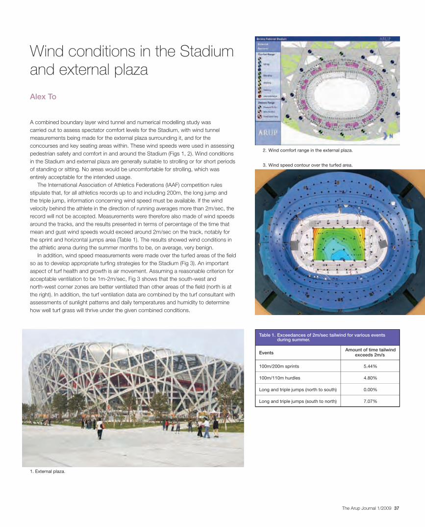
37The Arup Journal 1/2009
A combined boundary layer wind tunnel and numerical modelling study was carried out to assess spectator comfort levels for the Stadium, with wind tunnel measurements being made for the external plaza surrounding it, and for the concourses and key seating areas within. These wind speeds were used in assessing pedestrian safety and comfort in and around the Stadium (Figs 1, 2). Wind conditions in the Stadium and external plaza are generally suitable to strolling or for short periods of standing or sitting. No areas would be uncomfortable for strolling, which was entirely acceptable for the intended usage.
The International Association of Athletics Federations (IAAF) competition rules stipulate that, for all athletics records up to and including 200m, the long jump and the triple jump, information concerning wind speed must be available. If the wind velocity behind the athlete in the direction of running averages more than 2m/sec, the record will not be accepted. Measurements were therefore also made of wind speeds around the tracks, and the results presented in terms of percentage of the time that mean and gust wind speeds would exceed around 2m/sec on the track, notably for the sprint and horizontal jumps area (Table 1). The results showed wind conditions in the athletic arena during the summer months to be, on average, very benign.
In addition, wind speed measurements were made over the turfed areas of the field so as to develop appropriate turfing strategies for the Stadium (Fig 3). An important aspect of turf health and growth is air movement. Assuming a reasonable criterion for acceptable ventilation to be 1m-2m/sec, Fig 3 shows that the south-west and north-west corner zones are better ventilated than other areas of the field (north is at the right). In addition, the turf ventilation data are combined by the turf consultant with assessments of sunlight patterns and daily temperatures and humidity to determine how well turf grass will thrive under the given combined conditions.
Alex To
Wind conditions in the Stadium and external plaza
3. Wind speed contour over the turfed area.
2. Wind comfort range in the external plaza.
1. External plaza.
Table 1. Exceedances of 2m/sec tailwind for various events during summer.
EventsAmount of time tailwind
exceeds 2m/s
100m/200m sprints 5.44%
100m/110m hurdles 4.80%
Long and triple jumps (north to south) 0.00%
Long and triple jumps (south to north) 7.07%
30223_Arup.indd 37 28/4/09 12:58:56
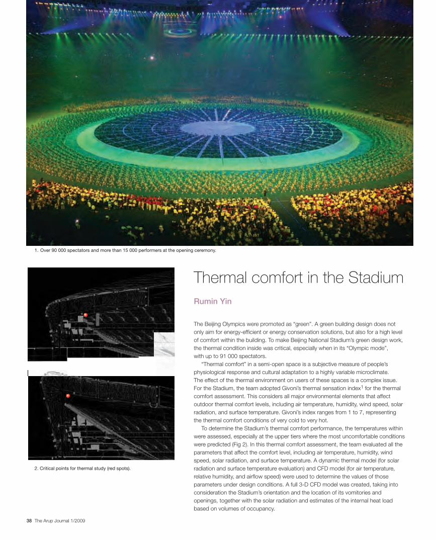
38 The Arup Journal 1/2009
The Beijing Olympics were promoted as “green”. A green building design does not only aim for energy-efficient or energy conservation solutions, but also for a high level of comfort within the building. To make Beijing National Stadium’s green design work, the thermal condition inside was critical, especially when in its “Olympic mode”, with up to 91 000 spectators.
“Thermal comfort” in a semi-open space is a subjective measure of people’s physiological response and cultural adaptation to a highly variable microclimate.
The effect of the thermal environment on users of these spaces is a complex issue. For the Stadium, the team adopted Givoni’s thermal sensation index1 for the thermal comfort assessment. This considers all major environmental elements that affect outdoor thermal comfort levels, including air temperature, humidity, wind speed, solar radiation, and surface temperature. Givoni’s index ranges from 1 to 7, representing the thermal comfort conditions of very cold to very hot.
To determine the Stadium’s thermal comfort performance, the temperatures within were assessed, especially at the upper tiers where the most uncomfortable conditions were predicted (Fig 2). In this thermal comfort assessment, the team evaluated all the parameters that affect the comfort level, including air temperature, humidity, wind speed, solar radiation, and surface temperature. A dynamic thermal model (for solar radiation and surface temperature evaluation) and CFD model (for air temperature, relative humidity, and airflow speed) were used to determine the values of those parameters under design conditions. A full 3-D CFD model was created, taking into consideration the Stadium’s orientation and the location of its vomitories and openings, together with the solar radiation and estimates of the internal heat load based on volumes of occupancy.
Rumin Yin
Thermal comfort in the Stadium
1. Over 90 000 spectators and more than 15 000 performers at the opening ceremony.
2. Critical points for thermal study (red spots).
30223_Arup.indd 38 28/4/09 12:59:07
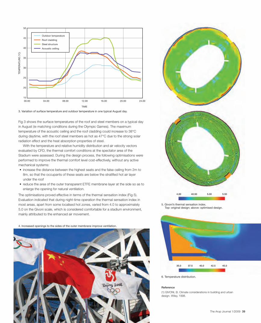
39The Arup Journal 1/2009
TIME
00.00 08.0004.00
50
45
40
35
30
25
20
15
12.00 16.00 20.00 24.00
TE
MP
ER
AT
UR
E (°C
)
Outdoor temperature
Roof cladding
Steel structure
Acoustic ceiling
35.0
4.00
37.5 40.0
40.50
42.5
5.00
45.0
5.50
Fig 3 shows the surface temperatures of the roof and steel members on a typical day
in August (ie matching conditions during the Olympic Games). The maximum
temperature of the acoustic ceiling and the roof cladding could increase to 38°C
during daytime, with the roof steel members as hot as 47°C due to the strong solar
radiation effect and the heat absorption properties of steel.
With the temperature and relative humidity distribution and air velocity vectors
evaluated by CFD, the thermal comfort conditions at the spectator area of the
Stadium were assessed. During the design process, the following optimisations were
performed to improve the thermal comfort level cost-effectively, without any active
mechanical systems:
8m, so that the occupants of these seats are below the stratified hot air layer
under the roof
enlarge the opening for natural ventilation.
The optimisations proved effective in terms of the thermal sensation index (Fig 5).
most areas, apart from some localised hot zones, varied from 4.0 to approximately
5.0 on the Givoni scale, which is considered comfortable for a stadium environment,
mainly attributed to the enhanced air movement.
Reference
(1) GIVONI, B. Climate considerations in building and urban
design. Wiley, 1998.
5. Givoni’s thermal sensation index. Top: original design; above: optimised design.
6. Temperature distribution.
3. Variation of surface temperature and outdoor temperature in one typical August day.
4. Increased openings to the sides of the outer membrane improve ventilation.
30223_Arup.indd 39 29/4/09 13:10:29
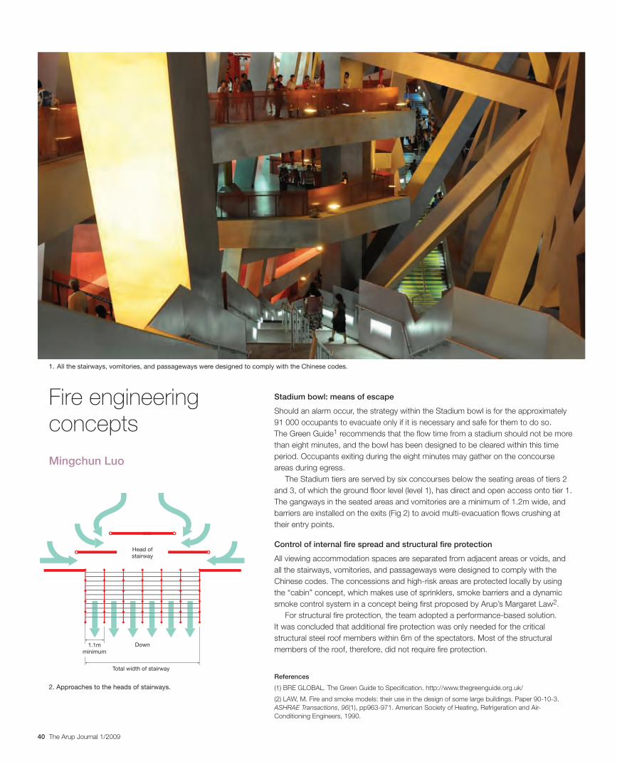
40 The Arup Journal 1/2009
Stadium bowl: means of escape
Should an alarm occur, the strategy within the Stadium bowl is for the approximately 91 000 occupants to evacuate only if it is necessary and safe for them to do so. The Green Guide1 recommends that the flow time from a stadium should not be more than eight minutes, and the bowl has been designed to be cleared within this time period. Occupants exiting during the eight minutes may gather on the concourse areas during egress.
The Stadium tiers are served by six concourses below the seating areas of tiers 2 and 3, of which the ground floor level (level 1), has direct and open access onto tier 1. The gangways in the seated areas and vomitories are a minimum of 1.2m wide, and barriers are installed on the exits (Fig 2) to avoid multi-evacuation flows crushing at their entry points.
Control of internal fire spread and structural fire protection
All viewing accommodation spaces are separated from adjacent areas or voids, and all the stairways, vomitories, and passageways were designed to comply with the Chinese codes. The concessions and high-risk areas are protected locally by using the “cabin” concept, which makes use of sprinklers, smoke barriers and a dynamic smoke control system in a concept being first proposed by Arup’s Margaret Law2.
For structural fire protection, the team adopted a performance-based solution. It was concluded that additional fire protection was only needed for the critical structural steel roof members within 6m of the spectators. Most of the structural members of the roof, therefore, did not require fire protection.
Head of
stairway
Down
Total width of stairway
1.1m
minimum
Mingchun Luo
2. Approaches to the heads of stairways.
References
(1) BRE GLOBAL. The Green Guide to Specification. http://www.thegreenguide.org.uk/
(2) LAW, M. Fire and smoke models: their use in the design of some large buildings. Paper 90-10-3. ASHRAE Transactions, 96(1), pp963-971. American Society of Heating, Refrigeration and Air-Conditioning Engineers, 1990.
Fire engineering concepts
1. All the stairways, vomitories, and passageways were designed to comply with the Chinese codes.
30223_Arup.indd 40 28/4/09 12:59:18
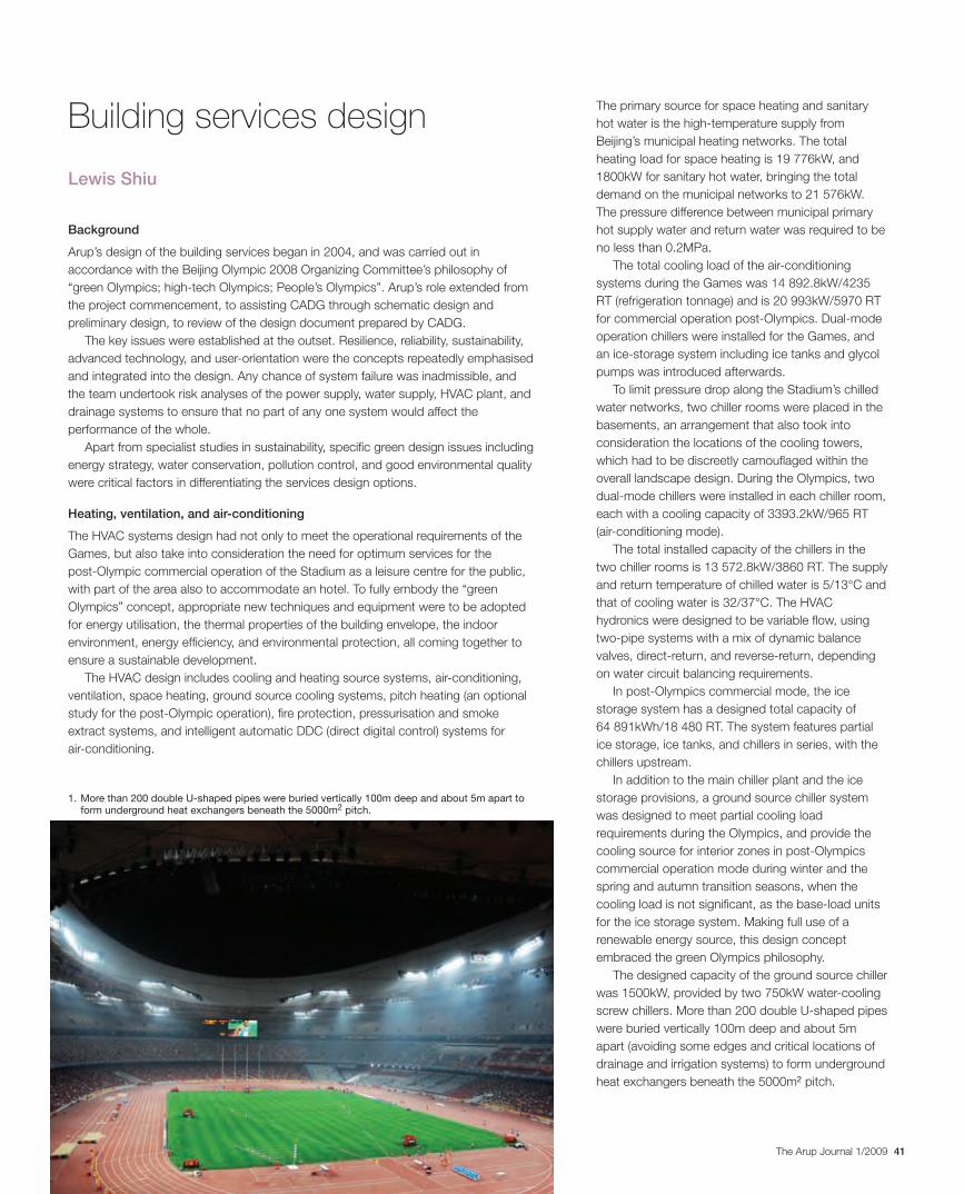
41The Arup Journal 1/2009
The primary source for space heating and sanitary hot water is the high-temperature supply from Beijing’s municipal heating networks. The total heating load for space heating is 19 776kW, and 1800kW for sanitary hot water, bringing the total demand on the municipal networks to 21 576kW. The pressure difference between municipal primary hot supply water and return water was required to be no less than 0.2MPa.
The total cooling load of the air-conditioning systems during the Games was 14 892.8kW/4235 RT (refrigeration tonnage) and is 20 993kW/5970 RT for commercial operation post-Olympics. Dual-mode operation chillers were installed for the Games, and an ice-storage system including ice tanks and glycol pumps was introduced afterwards.
To limit pressure drop along the Stadium’s chilled water networks, two chiller rooms were placed in the basements, an arrangement that also took into consideration the locations of the cooling towers, which had to be discreetly camouflaged within the overall landscape design. During the Olympics, two dual-mode chillers were installed in each chiller room, each with a cooling capacity of 3393.2kW/965 RT (air-conditioning mode).
The total installed capacity of the chillers in the two chiller rooms is 13 572.8kW/3860 RT. The supply and return temperature of chilled water is 5/13°C and that of cooling water is 32/37°C. The HVAC hydronics were designed to be variable flow, using two-pipe systems with a mix of dynamic balance valves, direct-return, and reverse-return, depending on water circuit balancing requirements.
In post-Olympics commercial mode, the ice storage system has a designed total capacity of 64 891kWh/18 480 RT. The system features partial ice storage, ice tanks, and chillers in series, with the chillers upstream.
In addition to the main chiller plant and the ice storage provisions, a ground source chiller system was designed to meet partial cooling load requirements during the Olympics, and provide the cooling source for interior zones in post-Olympics commercial operation mode during winter and the spring and autumn transition seasons, when the cooling load is not significant, as the base-load units for the ice storage system. Making full use of a renewable energy source, this design concept embraced the green Olympics philosophy.
The designed capacity of the ground source chiller was 1500kW, provided by two 750kW water-cooling screw chillers. More than 200 double U-shaped pipes were buried vertically 100m deep and about 5m apart (avoiding some edges and critical locations of drainage and irrigation systems) to form underground heat exchangers beneath the 5000m2 pitch.
Background
Arup’s design of the building services began in 2004, and was carried out in accordance with the Beijing Olympic 2008 Organizing Committee’s philosophy of “green Olympics; high-tech Olympics; People’s Olympics”. Arup’s role extended from the project commencement, to assisting CADG through schematic design and preliminary design, to review of the design document prepared by CADG.
The key issues were established at the outset. Resilience, reliability, sustainability, advanced technology, and user-orientation were the concepts repeatedly emphasised and integrated into the design. Any chance of system failure was inadmissible, and the team undertook risk analyses of the power supply, water supply, HVAC plant, and drainage systems to ensure that no part of any one system would affect the performance of the whole.
Apart from specialist studies in sustainability, specific green design issues including energy strategy, water conservation, pollution control, and good environmental quality were critical factors in differentiating the services design options.
Heating, ventilation, and air-conditioning
The HVAC systems design had not only to meet the operational requirements of the Games, but also take into consideration the need for optimum services for the post-Olympic commercial operation of the Stadium as a leisure centre for the public, with part of the area also to accommodate an hotel. To fully embody the “green Olympics” concept, appropriate new techniques and equipment were to be adopted for energy utilisation, the thermal properties of the building envelope, the indoor environment, energy efficiency, and environmental protection, all coming together to ensure a sustainable development.
The HVAC design includes cooling and heating source systems, air-conditioning, ventilation, space heating, ground source cooling systems, pitch heating (an optional study for the post-Olympic operation), fire protection, pressurisation and smoke extract systems, and intelligent automatic DDC (direct digital control) systems for air-conditioning.
Lewis Shiu
1. More than 200 double U-shaped pipes were buried vertically 100m deep and about 5m apart to form underground heat exchangers beneath the 5000m2 pitch.
Building services design
30223_Arup.indd 41 28/4/09 12:59:20
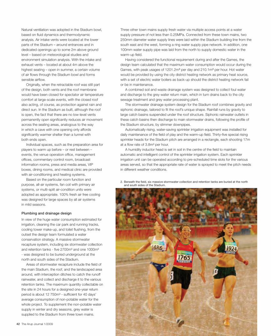
42 The Arup Journal 1/2009
Three other town mains supply fresh water via multiple access points at a water supply pressure of not less than 0.25MPa. Connected from these town mains, two 250mm diameter water supply lines were laid within the Stadium building line from the south east and the west, forming a ring water supply pipe network. In addition, one 100mm water supply pipe was laid from the north to supply domestic water in the warm-up field.
Having considered the functional requirement during and after the Games, the design team calculated that the maximum water consumption would occur during the Games, with peak usages of 1201.2m3 per day and 210.1m3 per hour. Hot water would be provided by using the city district heating network as primary heat source, with a set of electric water boilers as back-up should the district heating network fail or be in maintenance.
A combined soil and waste drainage system was designed to collect foul water and discharge to the grey water return main, which in turn drains back to the city sewage treatment and grey water processing plant.
The stormwater drainage system design for the Stadium roof combines gravity and siphonic drainage, tailored to fit the roof’s unique shape. Rainfall runs by gravity to large catch basins suspended under the roof structure. Siphonic rainwater outlets in these catch basins then discharge to main stormwater drains, following the profile of the Stadium structure, by slimmer downpipes.
Automatically rising, water-saving sprinkler irrigation equipment was installed for daily maintenance of the field of play and the warm-up field. Thirty-five special rising sprinkler heads for the Stadium pitch are arranged in a rectangle, each shooting 17m at a flow rate of 3.8m³ per hour.
A humidity inductor head is set in soil in the centre of the field to maintain automatic and intelligent control of the sprinkler irrigation system. Each sprinkler irrigation unit can be operated according to pre-scheduled time slots for the various areas served, so that the appropriate rate of water is sprayed to meet the pitch needs in different weather conditions.
Natural ventilation was adopted in the Stadium bowl, based on fluid dynamics and thermodynamic analysis. Air intake vents were located at the lower parts of the Stadium – around entrances and in dedicated openings up to some 2m above ground level – based on meteorological studies and environment simulation analysis. With the intake and exhaust vents – located at about 4m above the highest seating – open in summer, a certain volume of air flows through the Stadium bowl and forms sensible airflow.
Originally, when the retractable roof was still part of the design, both vents and the roof membrane would have been closed for spectator air temperature comfort at large-scale events, with the closed roof also acting, of course, as protection against rain and direct sun. In the Stadium as built, although the roof is open, the fact that there are no low-level vents permanently open significantly reduces air movement across the seating areas, analogous to the way in which a cave with one opening only affords significantly warmer shelter than a tunnel with both ends open.
Individual spaces, such as the preparation area for players to warm up before – or rest between – events, the venue operation office, management offices, commentary control room, broadcast information rooms, press and media areas, VIP boxes, dining rooms, and medical clinic are provided with air-conditioning and heating systems.
Based on the particular room function and purpose, all-air systems, fan coil with primary air systems, or multi-split air-condition units were adopted as appropriate. 100% fresh air free cooling was designed for large spaces by all air systems in mild seasons.
Plumbing and drainage design
In view of the huge water consumption estimated for irrigation, cleaning the car park and running tracks, cooling tower make-up, and toilet flushing, from the outset the design team formulated a water conservation strategy. A massive stormwater recapture system, including six stormwater collection and retention tanks - five 2700m³ and one 1000m³ - was designed to be buried underground at the north and south sides of the Stadium.
Areas of stormwater recapture include the field of the main Stadium, the roof, and the landscaped area around, with interception ditches to catch the runoff rainwater, and collect and discharge it to the various retention tanks. The maximum quantity collectable on the site in 24 hours for a designed one-year return period is about 12 750m³ - sufficient for 40 days’ average consumption of non-potable water for the whole project. To supplement the non-potable water supply in winter and dry seasons, grey water is supplied to the Stadium from three town mains.
2. Beneath the field, six massive stormwater collection and retention tanks are buried at the north and south sides of the Stadium.
30223_Arup.indd 42 28/4/09 12:59:23
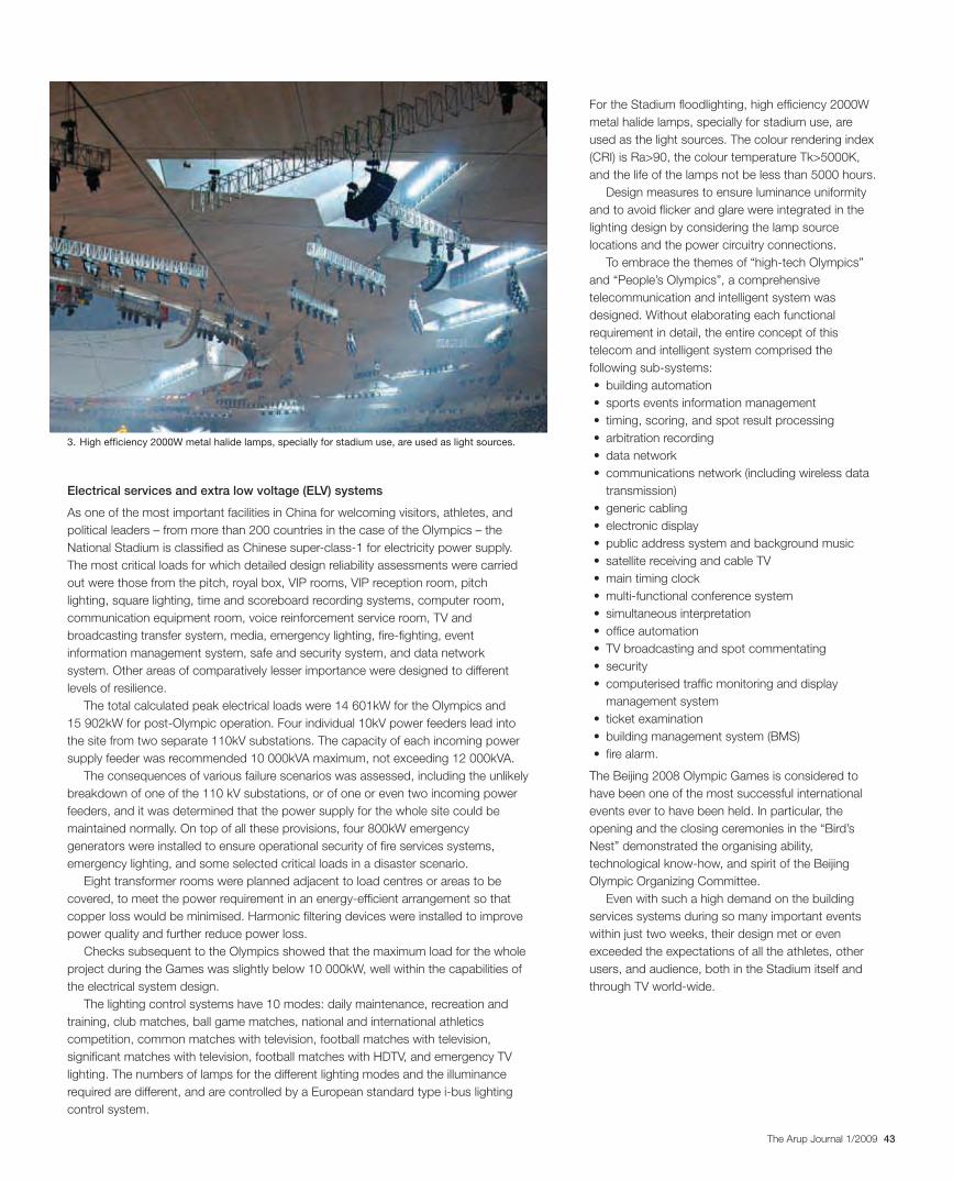
43The Arup Journal 1/2009
For the Stadium floodlighting, high efficiency 2000W metal halide lamps, specially for stadium use, are used as the light sources. The colour rendering index (CRI) is Ra>90, the colour temperature Tk>5000K, and the life of the lamps not be less than 5000 hours.
Design measures to ensure luminance uniformity and to avoid flicker and glare were integrated in the lighting design by considering the lamp source locations and the power circuitry connections.
To embrace the themes of “high-tech Olympics” and “People’s Olympics”, a comprehensive telecommunication and intelligent system was designed. Without elaborating each functional requirement in detail, the entire concept of this telecom and intelligent system comprised the following sub-systems: • buildingautomation• sportseventsinformationmanagement• timing,scoring,andspotresultprocessing• arbitrationrecording• datanetwork• communicationsnetwork(includingwirelessdata
transmission)• genericcabling• electronicdisplay• publicaddresssystemandbackgroundmusic• satellitereceivingandcableTV• maintimingclock• multi-functionalconferencesystem• simultaneousinterpretation• officeautomation• TVbroadcastingandspotcommentating• security• computerisedtrafficmonitoringanddisplay
management system• ticketexamination• buildingmanagementsystem(BMS)• firealarm.
The Beijing 2008 Olympic Games is considered to have been one of the most successful international events ever to have been held. In particular, the opening and the closing ceremonies in the “Bird’s Nest” demonstrated the organising ability, technological know-how, and spirit of the Beijing Olympic Organizing Committee.
Even with such a high demand on the building services systems during so many important events within just two weeks, their design met or even exceeded the expectations of all the athletes, other users, and audience, both in the Stadium itself and through TV world-wide.
Electrical services and extra low voltage (ELV) systems
As one of the most important facilities in China for welcoming visitors, athletes, and political leaders – from more than 200 countries in the case of the Olympics – the National Stadium is classified as Chinese super-class-1 for electricity power supply. The most critical loads for which detailed design reliability assessments were carried out were those from the pitch, royal box, VIP rooms, VIP reception room, pitch lighting, square lighting, time and scoreboard recording systems, computer room, communication equipment room, voice reinforcement service room, TV and broadcasting transfer system, media, emergency lighting, fire-fighting, event information management system, safe and security system, and data network system. Other areas of comparatively lesser importance were designed to different levels of resilience.
The total calculated peak electrical loads were 14 601kW for the Olympics and 15 902kW for post-Olympic operation. Four individual 10kV power feeders lead into the site from two separate 110kV substations. The capacity of each incoming power supply feeder was recommended 10 000kVA maximum, not exceeding 12 000kVA.
The consequences of various failure scenarios was assessed, including the unlikely breakdown of one of the 110 kV substations, or of one or even two incoming power feeders, and it was determined that the power supply for the whole site could be maintained normally. On top of all these provisions, four 800kW emergency generators were installed to ensure operational security of fire services systems, emergency lighting, and some selected critical loads in a disaster scenario.
Eight transformer rooms were planned adjacent to load centres or areas to be covered, to meet the power requirement in an energy-efficient arrangement so that copper loss would be minimised. Harmonic filtering devices were installed to improve power quality and further reduce power loss.
Checks subsequent to the Olympics showed that the maximum load for the whole project during the Games was slightly below 10 000kW, well within the capabilities of the electrical system design.
The lighting control systems have 10 modes: daily maintenance, recreation and training, club matches, ball game matches, national and international athletics competition, common matches with television, football matches with television, significant matches with television, football matches with HDTV, and emergency TV lighting. The numbers of lamps for the different lighting modes and the illuminance required are different, and are controlled by a European standard type i-bus lighting control system.
3. High efficiency 2000W metal halide lamps, specially for stadium use, are used as light sources.
30223_Arup.indd 43 28/4/09 12:59:26
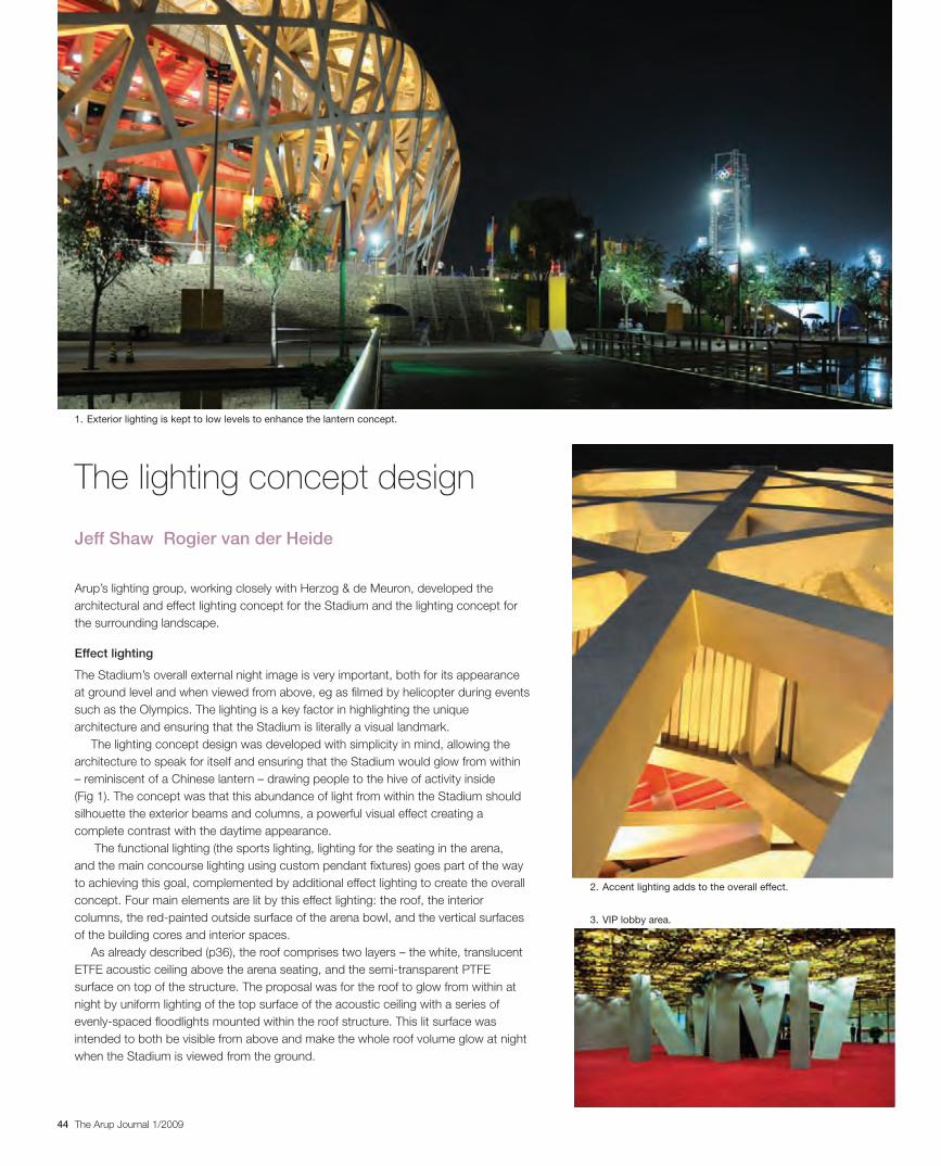
44 The Arup Journal 1/2009
The lighting concept design
Arup’s lighting group, working closely with Herzog & de Meuron, developed the architectural and effect lighting concept for the Stadium and the lighting concept for the surrounding landscape.
Effect lighting
The Stadium’s overall external night image is very important, both for its appearance at ground level and when viewed from above, eg as filmed by helicopter during events such as the Olympics. The lighting is a key factor in highlighting the unique architecture and ensuring that the Stadium is literally a visual landmark.
The lighting concept design was developed with simplicity in mind, allowing the architecture to speak for itself and ensuring that the Stadium would glow from within – reminiscent of a Chinese lantern – drawing people to the hive of activity inside (Fig 1). The concept was that this abundance of light from within the Stadium should silhouette the exterior beams and columns, a powerful visual effect creating a complete contrast with the daytime appearance.
The functional lighting (the sports lighting, lighting for the seating in the arena, and the main concourse lighting using custom pendant fixtures) goes part of the way to achieving this goal, complemented by additional effect lighting to create the overall concept. Four main elements are lit by this effect lighting: the roof, the interior columns, the red-painted outside surface of the arena bowl, and the vertical surfaces of the building cores and interior spaces.
As already described (p36), the roof comprises two layers – the white, translucent ETFE acoustic ceiling above the arena seating, and the semi-transparent PTFE surface on top of the structure. The proposal was for the roof to glow from within at night by uniform lighting of the top surface of the acoustic ceiling with a series of evenly-spaced floodlights mounted within the roof structure. This lit surface was intended to both be visible from above and make the whole roof volume glow at night when the Stadium is viewed from the ground.
Jeff Shaw Rogier van der Heide
1. Exterior lighting is kept to low levels to enhance the lantern concept.
2. Accent lighting adds to the overall effect.
3. VIP lobby area.
30223_Arup.indd 44 28/4/09 12:59:44
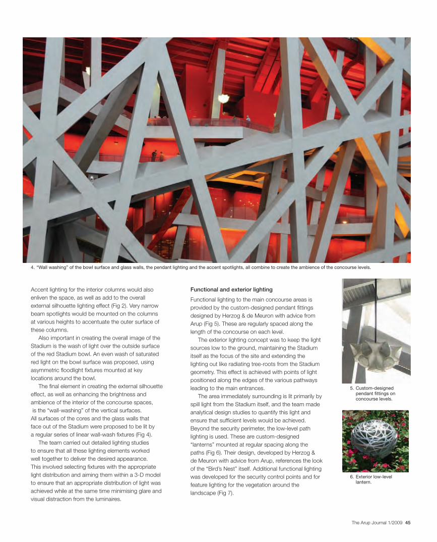
45The Arup Journal 1/2009
Functional and exterior lighting
Functional lighting to the main concourse areas is provided by the custom-designed pendant fittings designed by Herzog & de Meuron with advice from Arup (Fig 5). These are regularly spaced along the length of the concourse on each level.
The exterior lighting concept was to keep the light sources low to the ground, maintaining the Stadium itself as the focus of the site and extending the lighting out like radiating tree-roots from the Stadium geometry. This effect is achieved with points of light positioned along the edges of the various pathways leading to the main entrances.
The area immediately surrounding is lit primarily by spill light from the Stadium itself, and the team made analytical design studies to quantify this light and ensure that sufficient levels would be achieved. Beyond the security perimeter, the low-level path lighting is used. These are custom-designed “lanterns” mounted at regular spacing along the paths (Fig 6). Their design, developed by Herzog & de Meuron with advice from Arup, references the look of the “Bird’s Nest” itself. Additional functional lighting was developed for the security control points and for feature lighting for the vegetation around the landscape (Fig 7).
Accent lighting for the interior columns would also enliven the space, as well as add to the overall external silhouette lighting effect (Fig 2). Very narrow beam spotlights would be mounted on the columns at various heights to accentuate the outer surface of these columns.
Also important in creating the overall image of the Stadium is the wash of light over the outside surface of the red Stadium bowl. An even wash of saturated red light on the bowl surface was proposed, using asymmetric floodlight fixtures mounted at key locations around the bowl.
The final element in creating the external silhouette effect, as well as enhancing the brightness and ambience of the interior of the concourse spaces, is the “wall-washing” of the vertical surfaces. All surfaces of the cores and the glass walls that face out of the Stadium were proposed to be lit by a regular series of linear wall-wash fixtures (Fig 4).
The team carried out detailed lighting studies to ensure that all these lighting elements worked well together to deliver the desired appearance. This involved selecting fixtures with the appropriate light distribution and aiming them within a 3-D model to ensure that an appropriate distribution of light was achieved while at the same time minimising glare and visual distraction from the luminaires.
4. “Wall washing” of the bowl surface and glass walls, the pendant lighting and the accent spotlights, all combine to create the ambience of the concourse levels.
5. Custom-designed pendant fittings on concourse levels.
6. Exterior low-level lantern.
30223_Arup.indd 45 28/4/09 12:59:56
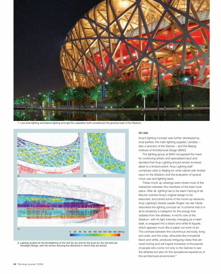
46 The Arup Journal 1/2009
On site
Arup’s lighting concept was further developed by local parties: the main lighting supplier, Landsky – also a sponsor of the Games – and the Beijing Institute of Architectural Design (BIAD).
The lighting group at BIAD recognised the need for continuing artistic and specialised input and decided that Arup Lighting should remain involved, albeit to a limited extent. Arup Lighting staff combined visits to Beijing for other clients with limited input on the Stadium and the evaluation of several mock-ups and lighting tests.
These mock-up viewings were where most of the interaction between the members of the team took place. After all, lighting has to be seen! Herzog & de Meuron wanted Arup’s original design to be executed, and joined some of the mock-up sessions. Arup Lighting’s Global Leader Rogier van der Heide described the lighting concept as “a scheme that is in all its simplicity a metaphor for the energy that radiates from the athletes. A red-lit core of the Stadium, with its light intensity changing as a heart beat, is wrapped into a black-and-white lit façade, which appears much like a paper cut work of art. The contrast between the voluminous red body, living and solid, and the crisp, silhouette-like immaterial black and white, produces intriguing vistas that are never boring and will inspire hundreds of thousands of people who come not only to the Games to see the athletes but also for the sensational experience of the architectural environment.”
7. Low-level lighting and feature lighting amongst the vegetation both complement the glowing heart of the Stadium.
8. Lighting studies for the floodlighting of the roof (a), (b,) and for the bowl (c); the red dots are floodlight fittings, with the arrows showing the directions in which they are aimed.
a)
c)
b)
0 20 40 60 80 100 120 140 160 180 200 lux
30223_Arup.indd 46 28/4/09 13:00:10
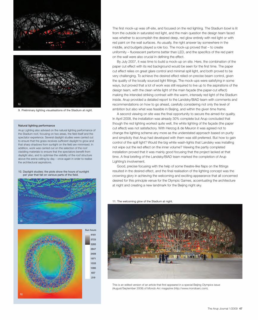
47The Arup Journal 1/2009
The first mock-up was off-site, and focused on the red lighting. The Stadium bowl is lit from the outside in saturated red light, and the main question the design team faced was whether to accomplish the desired deep, red glow entirely with red light or with red paint on the wall surfaces. As usually, the right answer lay somewhere in the middle, and budgets played a role too. The mock-up proved that – to create uniformity – fluorescent performs better than LED, and the specifics of the red paint on the wall were also crucial in defining the effect.
By July 2007, it was time to build a mock-up on site. Here, the combination of the paper cut effect with its red background would be seen for the first time. The paper cut effect relies on great glare control and minimal spill light, and both proved to be very challenging. To achieve the desired effect relied on precise beam control, given the quality of the locally sourced light fittings. The mock-ups were satisfying in some ways, but proved that a lot of work was still required to live up to the aspirations of the design team, with the clean white light of the main façade (the paper-cut effect) making the intended striking contrast with the warm, intensely red light of the Stadium inside. Arup provided a detailed report to the Landsky/BIAD team with comments and recommendations on how to go ahead, carefully considering not only the level of ambition but also what was feasible in Beijing, and within the given time frame.
A second viewing on site was the final opportunity to secure the aimed-for quality. In April 2008, the installation was already 30% complete but Arup concluded that though the red lighting worked quite well, the white lighting of the façade (the paper cut effect) was not satisfactory. With Herzog & de Meuron it was agreed not to change the lighting scheme any more as the understated approach based on purity and simplicity that Arup had developed with them was still preferred. But how to gain control of the spill light? Would the big white wash-lights that Landsky was installing not wipe out the red effect on the inner volume? Viewing the partly completed installation proved that it was mainly good focusing that the project lacked at that time. A final briefing of the Landsky/BIAD team marked the completion of Arup Lighting’s involvement.
Good, precise focusing with the help of some theatre-like flaps on the fittings resulted in the desired effect, and the final realisation of the lighting concept was the crowning glory in achieving the welcoming and exciting appearance that all concerned desired for this principle venue for the Olympic Games, accentuating the architecture at night and creating a new landmark for the Beijing night sky.
This is an edited version of an article that first appeared in a special Beijing Olympics issue (August/September 2008) of Mondo Arc magazine (http://www.mondoarc.com).
9. Preliminary lighting visualisations of the Stadium at night.
a)
b)
11. The welcoming glow of the Stadium at night.
Natural lighting performance
Arup Lighting also advised on the natural lighting performance of the Stadium roof, focusing on two areas, the field itself and the spectator experience. Several daylight studies were carried out to ensure that the grass receives sufficient daylight to grow and that sharp shadows from sunlight on the field are minimised. In addition, work was carried out on the selection of the roof cladding materials to ensure that the spectators benefit from daylight also, and to optimise the visibility of the roof structure above the arena ceiling by day – once again in order to realise the architectural aspirations.
4161
3723
3285
2847
2409
1971
1533
1095
657
219
Sun hours
10. Daylight studies: the plots show the hours of sunlight per year that fall on various parts of the field.
a)
b)
30223_Arup.indd 47 28/4/09 13:00:16
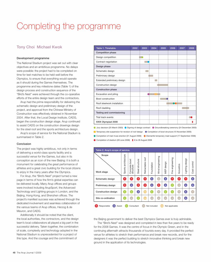
48 The Arup Journal 1/2009
Development programme
The National Stadium project was set out with clear objectives and an ambitious programme. No delays were possible: the project had to be completed on time for test matches to be held well before the Olympics, to ensure that everything would operate as it should during the Games themselves. The programme and key milestone dates (Table 1) of the design process and construction sequence of the “Bird’s Nest” were achieved through the co-operative efforts of the entire design team and the contractors.
Arup had the prime responsibility for delivering the schematic design and preliminary design of the project, and approval from the Chinese Ministry of Construction was effectively obtained in November 2004. After that, the Local Design Institute, CADG, began the construction design stage. Arup continued to assist CADG on the construction drawings design for the steel roof and the sports architecture design.
Arup’s scope of service for the National Stadium is summarised in Table 2.
Conclusion
The project was highly ambitious, not only in terms of delivering a world-class sports facility and a successful venue for the Games, but also in its conception as an icon of the new Beijing: it is both a monument for celebrating the great performance of athletes and a great civic building for the local citizens to enjoy in the many years after the Olympics.
For Arup, the “Bird’s Nest” project turned a new page in terms of how the firm’s global expertise can be delivered locally. Many Arup offices and groups were involved including ArupSport, the Advanced Technology and Lighting groups in London, and the Beijing, Hong Kong, and Shenzhen offices. The project’s manifest success was achieved through the dedicated involvement and seamless collaboration of the various teams of Arup offices, Herzog & de Meuron, and CADG.
Additionally it should be noted that the client, the local authorities, the contractors, and the design team’s local collaborators all played a big part in the successful delivery. Taken together, the combination of scale, complexity and technology adopted in the National Stadium is unprecedented for a project of this type. And the courage and the commitment of
the Beijing government to deliver the best Olympics Games ever is truly admirable.The “Bird’s Nest” was designed and completed in less than five years to be ready
for the 2008 Games. It was the centre of focus in the Olympic Green, and in the continuing aftermath attracts thousands of tourists every day. It provided the perfect venue for athletes to stretch their performance and break new records, and for the designers it was the perfect building to stretch innovative thinking and break new ground in the application of its technologies.
Tony Choi Michael Kwok
Completing the programme
Design competition
Construction design
Preliminary design
Extended preliminary design
Contract negotiation
Schematic design
Bowl construction
Roof steelwork installation
Roof cladding
Excavation and piling
Competition phase
2002Table 1. Timetable. 2003 2004 2005 2006 2007 2008
Design phase
Construction phase
Testing and commissioning
XXIX Olympiad 2008
Trial track events
Jury decision (25 March 2003) Groundbreaking ceremony (24 December 2003)Signing of design contract
Completion of stadium (28 June 2008) 8 to 28 August 2008
Dismantle temporary mast support (17 September 2006)Completion of main truss erection (31 August 2006)
Temporary site suspension for revision of roof design Completion of bowl structure (15 November 2005)
Table 2. Arup’s scope of service.
Schematic design
Work stage
Scope
naniCR A
Preliminary design
Construction design
Site co-ordination
Responsible Assist Consultant Not included Not applicable
Fire e
ng
ineeri
ng
Co
ncre
te b
ow
lstr
uctu
re
Sp
ort
s a
rch
itectu
re
Ste
el str
uctu
re
Win
d e
ng
ineeri
ng
ME
P d
esig
n
Retr
acta
ble
ro
of
Fo
un
datio
n
Co
st
co
ntr
ol
Lig
htin
g d
esig
n
Aco
ustics
ni
C
A
R
A
CA
A
R
C
C
R
R
C
A
R
R
na
na
R
R
ni
C
A
A
ni
ni
R
ni
ni
C
A
A
ni
C
C
R
ni
ni
R
ni
ni ni
A
A
30223_Arup.indd 48 29/4/09 15:18:36
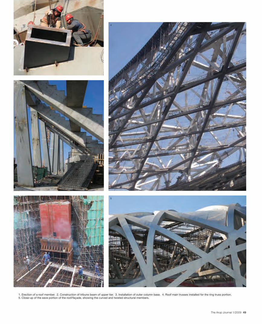
49The Arup Journal 1/2009
1. Erection of a roof member. 2. Construction of tribune beam of upper tier. 3. Installation of outer column base. 4. Roof main trusses installed for the ring truss portion. 5. Close-up of the eave portion of the roof/façade, showing the curved and twisted structural members.
1
2
3
4
5
30223_Arup.indd 49 28/4/09 13:00:32
Authors
Stephen Burrows is a Principal of Arup in the San Francisco office, and was the Global Leader of ArupSport and the Project Director for the design of the Beijing National Stadium from competition stage through the schematic design stage.
Tony Choi is an Associate Director of Arup in the Hong Kong office, and was Project Manager and discipline leader for the Stadium’s structural design after the schematic design stage.
Xiaonian Duan is an Associate of Arup in the Advanced Technology and Research group in London. He was discipline specialist for the seismic engineering design of the Stadium.
Goman Ho is a Director of Arup and leader of the structural team in the Beijing office. He was the expert reviewer for the seismic design of the Stadium.
Michael Kwok is a Director of Arup in Hong Kong and in China. He was the leader of the Beijing office and the Project Director of the Beijing National Stadium project after the schematic design stage.
Kylie Lam is an Associate of Arup in the Hong Kong office. She was the engineer for the analytical design of the Stadium roof.
Thomas Lam, formerly an Associate of Arup in the Hong Kong office, was project engineer for the structural design of the Stadium after the schematic design stage.
Mingchun Luo is a Technical Director of Arup in the Hong Kong office. He led the fire engineering concept design of the Stadium.
John Lyle is a Director of Arup with the Advanced Technology + Research London group. He led the Stadium’s retractable roof structural and mechanisation design team.
J Parrish is a Director of ArupSport in the London office. He led the sports architecture design of the Stadium.
Jeff Shaw is an Associate Director of Arup Lighting in the London office. He was responsible for advising Herzog & de Meuron on the development of the architectural, effect, and landscape lighting design for the Stadium.
Lewis Shiu is a Director of Arup and group leader of the Beijing office. He was Project Manager for the building services design of the Stadium.
Martin Simpson is an Associate Director of ArupSport in the Manchester office. He was lead structural engineer of ArupSport in the roof design of the Stadium from competition stage through schematic design stage.
Alex To is a senior engineer with Arup in the Hong Kong office. He was the wind expert in the wind engineering design of the Beijing National Stadium.
Rogier van der Heide is a Director of Arup Lighting in the Netherlands and is the global leader of Arup Lighting. With BIAD and Landsky, he developed and detailed the architectural feature lighting and event lighting for the Stadium.
Rumin Yin is an Associate with Arup in the Hong Kong office. He was project engineer in the study of environmental thermal comfort of the Stadium.
Credits
Client: National Stadium Co Ltd Promoters: Beijing Municipal Planning Commission and Beijing Organizing Committee for the Games of the XXIX Olympiad Architect: Herzog & de Meuron Architekten AG Associate architect/civil engineer: Chinese Architectural Design & Research Group SMEP engineering, acoustics and fire strategy, lighting, and sports architecture: Arup – Francesco Anselmo, Mark Arkinstall, Hazel Ashton, Martin Austin, Garry Banks, Daniel Bartminn, Fergus Begley, Felix Beyreuther, Joanna Black, Chris Brewis, Graham Britton, Stephen Burrows, Neil Carstairs, Jon Carver, Rachel Chaloner, Ernest Chan, Maverick Chan, Power Chan, Vincent Cheng, Yu-Lung Cheng, ZJ Cheng, James Cheung, Tony Choi, Kenneth Chong, Simon Chung, Cormac Clearly, Christopher Clifford, Dan Clipsom, Chris Cole, Colin Curtis, Tony Day, Roy Denoon, Lin-Nan Duan, Xiaonian Duan, Gerry Eccles, Emily Emerson, Paul Entwistle, Mike Farrell, Robin Firth, Maggue Fu, Y Fu, David Gration, Kathy Gubbins, Stephen Hendry, Jason Hewitt, Colin Ho, Goman Ho, YK Ho, Trevor Hodgson, Peter Howe, Matthew Derenzy Jones, Vincent Keasberry, Charlie Kendall, Lee Kirby, Michael Kwok, David Lai, Francis Lam, Kylie Lam, Thomas Lam, JF Lao, Pablo Lazo, Clive Lewis, Mark Lewis, H Li, Jing-Yu Li, L Li, GY Liu, Louis Liu, Peng Liu, Rob Livesey, Peter Llewelyn, Mingchun Luo, Yong-Qiang Luo, John Lyle, Simon Mabey, Charles Macdonald, Toby McCorry, Burkhard Miehe, Richard Morris, Erin Morrow, Donie O’Loughlin, Darren Paine, J Parrish, Tom Pearson, Azhar Quaiyoom, Sreejit Raghu, Roland Reinardy, Paul Richardson, Marcel Ridyard, Matthew Salisbury, Andrew Sedgwick, Jeff Shaw, Jon Shillibeer, Lewis Shiu, Flora Shum, Martin Simpson, Jim Smith, Rob Smith, Joe Stegers, Jason Tam, Arra Tan, Johnson Tang, Graeme Taylor, Nikita Taylor, Jeff Teerlinck, Alex To, Roland Trim, David Twiss, Eugene Uys, Rogier van der Heide, Alexandra van Tintelen, David Vesey, John Waite, Bai-Qian Wan, Timothy Wan, York Wang, YY Wang, Trevor Wheatley, Andrew Wilkinson, Michael Willford, Alastair Wilson, CW Wong, Stella Wong, Terry Wong, Andrew Woodhouse, Freddie Xu, Lucy Xu, Jimmy Yam, Jian-Feng Yao, Jackie Yau, Raymond Yau, Kenneth Yeung, Raymond Yin, Rumin Yin, Peter Young, Fiona Yuen, Julian Zheng Main contractors: Beijing Urban Construction Group and CITIC International Contracting Inc Lighting supplier: Landsky Lighting consultant: Beijing Institute of Architectural Design.
Illustrations: Arup with the following exceptions: Front cover, pp2-3, 7, 9(3), 10(8), 11(9, 10), 14(14), 15, 31, 35, 37(1), 38(1), 41(1), 42(2), 43(3), 44(5), 46(7), 47(11) Dreamstime; pp5(1, 2), 18(11), 26(3), 27(6, 7), 30(8), 33(6), 36(1, 4), 39(3), 40(2), 48(1, 2) Nigel Whale; pp5(3), 19(15, 16), 28(2) ©Herzog & de Meuron; p11(11) Xiao Long; pp14(15), 23(15), 26(5), 40(1), 44(1, 2), 45(4) J Parrish; pp16(5), 18(10), 51, back cover Ben McMillan; pp22(8), 23(10-14) CADG; p24(1) Marcel Lam; p32(1) Philip Dilley; pp32(2), 49(1) Chas Pope; pp33(7), 34(1), 49(4) Rory McGowan; p36(2) Martin Saunders; p36(3) Jeremy Stern; pp39(4), 49(5) Chris Dite; p45(6) Lewis Shiu.
“It was the best, most comfortable and most accessible facility I have ever worked in at an Olympics. There wasn’t a photographer who worked in the Stadium who had a single complaint. I can’t tell how happy everyone was. I wish all stadiums were that easy to work in. The moat was wide, accommodated two rows of photographers and was the perfect height. The moats around the Stadium in other locations were perfect also. The head on platform was also the right height, width and size. Plenty of room for all of the photographers to work.” Gary Hershorn, Reuters News editor and veteran photographer of five Olympics.
50 The Arup Journal 1/2009
30223_Arup.indd 50 28/4/09 13:00:47
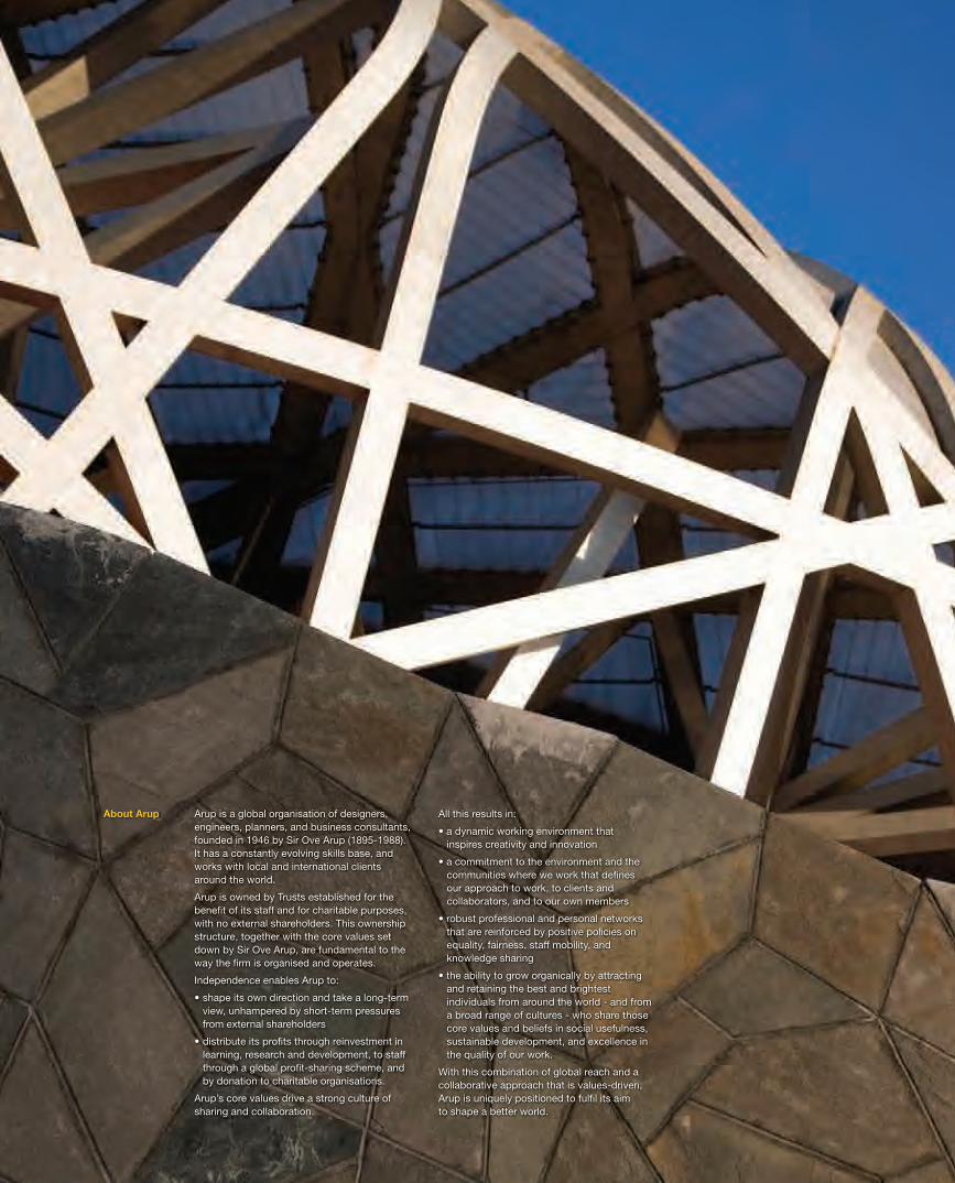
51The Arup Journal 1/2009
Arup is a global organisation of designers, engineers, planners, and business consultants, founded in 1946 by Sir Ove Arup (1895-1988). It has a constantly evolving skills base, and works with local and international clients around the world.
Arup is owned by Trusts established for the benefi t of its staff and for charitable purposes, with no external shareholders. This ownership structure, together with the core values set down by Sir Ove Arup, are fundamental to the way the fi rm is organised and operates.
Independence enables Arup to:
• shape its own direction and take a long-term view, unhampered by short-term pressures from external shareholders
• distribute its profi ts through reinvestment in learning, research and development, to staff through a global profi t-sharing scheme, and by donation to charitable organisations.
Arup’s core values drive a strong culture ofsharing and collaboration.
All this results in:
• a dynamic working environment that inspires creativity and innovation
• a commitment to the environment and the communities where we work that defi nesour approach to work, to clients and collaborators, and to our own members
• robust professional and personal networks that are reinforced by positive policies on equality, fairness, staff mobility, and knowledge sharing
• the ability to grow organically by attractingand retaining the best and brightest individuals from around the world - and from a broad range of cultures - who share those core values and beliefs in social usefulness, sustainable development, and excellence in the quality of our work.
With this combination of global reach and a collaborative approach that is values-driven,Arup is uniquely positioned to fulfi l its aim to shape a better world.
About Arup
30223_Arup.indd 51 28/4/09 13:00:57
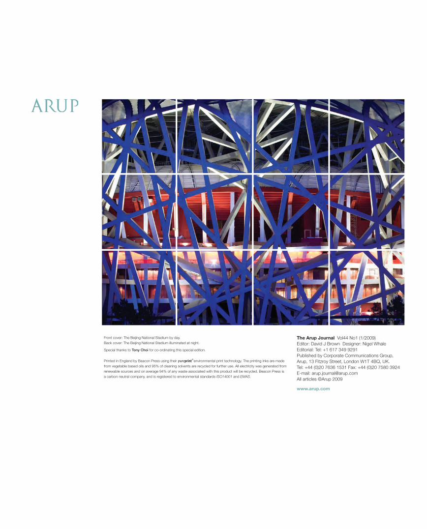
The Arup Journal Vol44 No1 (1/2009) Editor: David J Brown Designer: Nigel Whale Editorial: Tel: +1 617 349 9291 Published by Corporate Communications Group, Arup, 13 Fitzroy Street, London W1T 4BQ, UK. Tel: +44 (0)20 7636 1531 Fax: +44 (0)20 7580 3924 E-mail: [email protected] All articles ©Arup 2009
www.arup.com
Front cover: The Beijing National Stadium by day. Back cover: The Beijing National Stadium illuminated at night.
Special thanks to Tony Choi for co-ordinating this special edition.
Printed in England by Beacon Press using their ®environmental print technology. The printing inks are made from vegetable based oils and 95% of cleaning solvents are recycled for further use. All electricity was generated from renewable sources and on average 94% of any waste associated with this product will be recycled. Beacon Press is a carbon neutral company, and is registered to environmental standards ISO14001 and EMAS.
30223_Arup.indd 52 28/5/09 08:53:30