
T/Guard™-408 and -408XT - Neoptix · Neoptix Canada LP © Document . G1044. r08 5 . 2 W. ARNING....
112
Neoptix Canada LP © Document G1044r08 1 T/Guard™-408 and -408XT Fiber Optic Thermometer Systems for Power Transformers 4-, 6-, 8-, 10-, 12- and 16-Channel Versions With OptiLink-II software Qualitrol Company LLC / Neoptix Canada LP 1415, rue Frank-Carrel, Suite 220 Québec, QC, G1N 4N7 Canada Tel: 418-687-2500 Fax: 418-687-2524 [email protected] Proprietary notice: Details of design and engineering are the exclusive property of Neoptix Canada LP and Qualitrol Company LLC and are strictly confidential. The information given herein is subject to change, at any time and without notice. All rights are reserved. The information in this document may not be reproduced or passed on in any manner without prior written consent of Qualitrol Company LLC. Qualitrol Company LLC shall not be liable for technical or editorial errors or omissions contained herein; nor for incidental or consequential damages resulting from the furnishing, performance, or use of this material. All trademarks are the property of their respective owners. Part number: G1044r08 (July 2015)
-
Upload
phamnguyet -
Category
Documents
-
view
212 -
download
0
Transcript of T/Guard™-408 and -408XT - Neoptix · Neoptix Canada LP © Document . G1044. r08 5 . 2 W. ARNING....

Neoptix Canada LP © Document G1044r08 1
T/Guard™-408 and -408XT
Fiber Optic Thermometer Systems for Power Transformers 4-, 6-, 8-, 10-, 12- and 16-Channel Versions
With OptiLink-II software
Qualitrol Company LLC / Neoptix Canada LP 1415, rue Frank-Carrel, Suite 220 Québec, QC, G1N 4N7 Canada Tel: 418-687-2500 Fax: 418-687-2524 [email protected]
Proprietary notice: Details of design and engineering are the exclusive property of Neoptix Canada LP and Qualitrol Company LLC and are strictly confidential. The information given herein is subject to change, at any time and without notice. All rights are reserved. The information in this document may not be reproduced or passed on in any manner without prior written consent of Qualitrol Company LLC. Qualitrol Company LLC shall not be liable for technical or editorial errors or omissions contained herein; nor for incidental or consequential damages resulting from the furnishing, performance, or use of this material. All trademarks are the property of their respective owners.
Part number: G1044r08 (July 2015)
Neoptix Canada LP © Document G1044r08 2
1 TABLE OF CONTENTS 1 TABLE OF CONTENTS ............................................................................................................................................................................2 2 WARNING ...............................................................................................................................................................................................5 3 IMPORTANT SECURITY DISCLAIMER ........................................................................................................................................6 4 END USER LICENSE AND SOFTWARE WARRANTY AGREEMENT .....................................................................................7
4.1 T/GUARD 408 WARRANTY NOTICE ............................................................................................................................................................................... 10 5 INTRODUCTION ................................................................................................................................................................................ 11
5.1 CALIBRATION ................................................................................................................................................................................................................ 12 5.2 TRANSFORMER APPLICATIONS ....................................................................................................................................................................................... 12
6 INSTALLATION OF THE T/GUARD 408 ...................................................................................................................................... 13 6.1 MECHANICAL INSTALLATION ........................................................................................................................................................................................ 13 6.2 ELECTRICAL INSTALLATION .......................................................................................................................................................................................... 14
6.2.1 Connector Description ..................................................................................................................................................................................... 14 6.2.2 Probe Connections (Extension, Outside Transformer) .................................................................................................................................... 15 6.2.3 Analog Output Connections ............................................................................................................................................................................. 16
6.3 MATING CONNECTORS ................................................................................................................................................................................................... 17 7 USING THE KEYPAD MENUS ........................................................................................................................................................ 18
7.1 THE MAIN DISPLAY MENU ............................................................................................................................................................................................ 18 7.2 THE SETUP MENU ......................................................................................................................................................................................................... 21 7.3 THE GLOBAL TEMPERATURE MENU .............................................................................................................................................................................. 23 7.4 THE MINIMUM – MAXIMUM MENU ............................................................................................................................................................................... 23 7.5 THE CHANNEL ENABLE MENU ...................................................................................................................................................................................... 24 7.6 THE SIGNALS MENU ...................................................................................................................................................................................................... 24 7.7 THE RELAY CONDITION MENU...................................................................................................................................................................................... 26 7.8 THE RELAY FAILSAFE MENU ........................................................................................................................................................................................ 27 7.9 THE LOGGING MENU..................................................................................................................................................................................................... 27 7.10 THE PROTOCOL MENU (SERIAL) .................................................................................................................................................................................... 28
7.10.1 Neoptix ASCII Protocol ................................................................................................................................................................................... 29 7.10.2 Modbus Protocol .............................................................................................................................................................................................. 29 7.10.3 DNP 3.0 Protocol ............................................................................................................................................................................................. 29 7.10.4 IEC 60870-5-101 Protocol............................................................................................................................................................................... 29
7.11 THE TIME MENU ........................................................................................................................................................................................................... 30 7.12 THE ETHERNET MENU (FOR 408XT MODEL ONLY) ...................................................................................................................................................... 30
8 USING THE WEB INTERFACE (408XT MODEL)....................................................................................................................... 32 8.1 OVERVIEW .................................................................................................................................................................................................................... 32
8.1.1 User Management ............................................................................................................................................................................................ 32 8.1.2 Web Sessions .................................................................................................................................................................................................... 32 8.1.3 Duplicating Custom Configurations between T/Guard 408 Devices .............................................................................................................. 32
8.2 NETWORKING THE T/GUARD 408 DEVICE .................................................................................................................................................................... 32 8.3 FIRST APPROACH: SETTING UP A PRIVATE NETWORK (STATIC IP) ................................................................................................................................. 33 8.4 WORKING WITH THE INTERNET BROWSER (FIXED IP ADDRESS) .................................................................................................................................... 35 8.5 SECOND APPROACH: SETTING UP DYNAMIC ADDRESS (DHCP SERVER) ...................................................................................................................... 35 8.6 THE T/GUARD 408XT WEB APPLICATION .................................................................................................................................................................... 37
8.6.1 Note Concerning the Web Browser Cache ...................................................................................................................................................... 37 8.6.2 Login Page ....................................................................................................................................................................................................... 38 8.6.3 Configurable Colored Dots in the Web Page Headers .................................................................................................................................... 39
8.7 WEB PAGES FOR AN ADMINISTRATOR USER .................................................................................................................................................................. 40 8.7.1 T/Guard 408XT Home Page ............................................................................................................................................................................ 40 8.7.2 Status Page (Default View) .............................................................................................................................................................................. 41 8.7.3 Status Page (Raw Ethernet Stats View) ........................................................................................................................................................... 42 8.7.4 Status Page (Formatted Ethernet Statistics View) ........................................................................................................................................... 42 8.7.5 Time Setup Page (and NTP servers) ................................................................................................................................................................ 43 8.7.6 Labels and Interfaces Page .............................................................................................................................................................................. 43 8.7.7 Manage Serial Port Protocols ......................................................................................................................................................................... 44 8.7.8 Manage Ethernet Smart-Grid Protocols .......................................................................................................................................................... 45 8.7.9 Configuration Web Page for the IEC 61850 Protocol ..................................................................................................................................... 46 8.7.10 Configuration Web Page for the DNP 3.0 Protocol ........................................................................................................................................ 47 8.7.11 Configuration Web Page for the IEC 60870-5-104 Protocol .......................................................................................................................... 48 8.7.12 Configuration Web Page for the Modbus Over Ethernet Protocol ................................................................................................................. 48
Neoptix Canada LP © Document G1044r08 3
8.7.13 File Transfer..................................................................................................................................................................................................... 49 8.7.14 User Management Page ................................................................................................................................................................................... 50 8.7.15 Add New User Page ......................................................................................................................................................................................... 50 8.7.16 Modify Main User Role Page .......................................................................................................................................................................... 51 8.7.17 Modify / Delete Other User Page .................................................................................................................................................................... 51 8.7.18 Log Download (and Delete) Page ................................................................................................................................................................... 52 8.7.19 Log Viewer Page .............................................................................................................................................................................................. 53 8.7.20 Log Setting Page .............................................................................................................................................................................................. 53 8.7.21 Relay Condition Overview Page ...................................................................................................................................................................... 54 8.7.22 Relay Setup Page ............................................................................................................................................................................................. 54 8.7.23 Relay Condition Setting Page .......................................................................................................................................................................... 55 8.7.24 Relay Condition Example................................................................................................................................................................................. 56 8.7.25 Event Logging Download Page ....................................................................................................................................................................... 57 8.7.26 Alarm Management Page ................................................................................................................................................................................ 58 8.7.27 Optical Channel Parameter Overview Page ................................................................................................................................................... 58 8.7.28 Temperature Channel Setting Page ................................................................................................................................................................. 58 8.7.29 Global Probe Parameter Setting Page ............................................................................................................................................................ 59 8.7.30 Visual Temperature Page................................................................................................................................................................................. 59 8.7.31 TransLife™ Result Page .................................................................................................................................................................................. 60 8.7.32 TransLife™ Setup Page ................................................................................................................................................................................... 61
8.8 WEB PAGES FOR A GUEST USER .................................................................................................................................................................................... 62 8.8.1 Login Page ....................................................................................................................................................................................................... 62 8.8.2 Home Page ....................................................................................................................................................................................................... 63 8.8.3 Status Page ....................................................................................................................................................................................................... 63 8.8.4 Time Setup Page............................................................................................................................................................................................... 63 8.8.5 Labels and Interfaces Page .............................................................................................................................................................................. 64 8.8.6 Serial Protocols ................................................................................................................................................................................................ 64 8.8.7 Ethernet Protocols ........................................................................................................................................................................................... 64 8.8.8 Log Download Page ........................................................................................................................................................................................ 65 8.8.9 Log Viewer Page .............................................................................................................................................................................................. 65 8.8.10 Log Setting Page .............................................................................................................................................................................................. 65 8.8.11 Relay Condition Overview ............................................................................................................................................................................... 65 8.8.12 Relay Status Overview Page ............................................................................................................................................................................ 66 8.8.13 Event Logging Download Page ....................................................................................................................................................................... 66 8.8.14 Alarm Management Page ................................................................................................................................................................................ 66 8.8.15 Temperature Channel Overview ...................................................................................................................................................................... 66 8.8.16 Global Parameter Page ................................................................................................................................................................................... 67 8.8.17 Visual Temperature Page................................................................................................................................................................................. 67 8.8.18 TransLife™ Results .......................................................................................................................................................................................... 67
9 OPTILINK-II SOFTWARE DESCRIPTION (FOR THE 408) ..................................................................................................... 68 9.1 INSTALLATION AND INITIAL OPERATION ....................................................................................................................................................................... 68 9.2 ACQUIRE AND DISPLAY TEMPERATURE DATA ............................................................................................................................................................... 69
9.2.1 Data Acquisition, Logging and Graphing Rates .............................................................................................................................................. 71 9.2.2 Graphs .............................................................................................................................................................................................................. 71
9.3 OPTICAL CHANNEL SETTINGS TOOL .............................................................................................................................................................................. 71 9.4 RELAY CONDITIONS TOOL ............................................................................................................................................................................................ 72 9.5 DOWNLOAD FILES TOOL ............................................................................................................................................................................................... 73 9.6 GENERAL PARAMETERS ................................................................................................................................................................................................ 73 9.7 ETHERNET PROTOCOL PARAMETERS ............................................................................................................................................................................. 74 9.8 SERIAL PROTOCOL PARAMETERS .................................................................................................................................................................................. 75 9.9 FIRMWARE UPDATE TOOL ............................................................................................................................................................................................. 75 9.10 UPLOAD SETTINGS TOOL............................................................................................................................................................................................... 75 9.11 TROUBLESHOOTING....................................................................................................................................................................................................... 75
10 APPENDIX A – SOFTWARE UPGRADE VIA WEB INTERFACE .......................................................................................... 77 11 APPENDIX B – EXAMPLE OF A DOWNLOADED STATUS TEXT FILE .............................................................................. 79 12 APPENDIX C – USING OPTILINK TO COMMUNICATE WITH THE T/GUARD 408 .......................................................... 81
12.1 USING OPTILINK ........................................................................................................................................................................................................... 81 12.2 LOGGING TEMPERATURES IN WINDOWS WITH OPTILINK .............................................................................................................................................. 83 12.3 VIEWING TEMPERATURE DATA IN OPTILINK................................................................................................................................................................. 85 12.4 RECOMMENDED CONFIGURATION, FOR TRANSFORMER APPLICATIONS ......................................................................................................................... 86
12.4.1 Interpretation of Probe Intensity Results ......................................................................................................................................................... 86 13 APPENDIX D – MODBUS COMMUNICATION PROTOCOL .................................................................................................. 88
Neoptix Canada LP © Document G1044r08 4
13.1 CONFIGURING THE MODBUS OPTION ............................................................................................................................................................................. 88 13.2 SUPPORTED SERIAL TRANSMISSION MODE .................................................................................................................................................................... 88 13.3 RTU TRANSMISSION MODE .......................................................................................................................................................................................... 88 13.4 MODBUS FUNCTION CODE AND REGISTER ADDRESSES ................................................................................................................................................. 89
13.4.1 Modbus Protocol Map Registers ..................................................................................................................................................................... 89 13.5 MODBUS EXCEPTION CODES ......................................................................................................................................................................................... 93 13.6 MODSCAN EXAMPLES ................................................................................................................................................................................................... 93 13.7 USING MODSCAN OVER ETHERNET ............................................................................................................................................................................... 94 13.8 MONITORING MULTIPLE T/GUARD 408 SYSTEMS ........................................................................................................................................................... 95
13.8.1 Writing Parameters .......................................................................................................................................................................................... 95 13.8.2 Data logging .................................................................................................................................................................................................... 96
13.9 USING MODSCAN TRIAL VERSION TO TEST THE MODBUS SERIAL PROTOCOL ON THE 408 ............................................................................................ 96 14 APPENDIX E – OPTIONAL RS-485 TO USB CONVERTER ..................................................................................................... 99 15 APPENDIX F – COMMISSIONING PROCEDURE FOR NEOPTIX T/GUARD-408 ........................................................... 100
15.1 INTRODUCTION ............................................................................................................................................................................................................ 100 15.2 REQUIRED TOOLS ........................................................................................................................................................................................................ 100 15.3 SOFTWARE DOWNLOADS ............................................................................................................................................................................................. 100 15.4 TESTING PROBES ......................................................................................................................................................................................................... 100 15.5 ANALOG OUTPUT TESTING ........................................................................................................................................................................................... 101 15.6 RELAY TESTING ........................................................................................................................................................................................................... 101 15.7 CONCLUSION ............................................................................................................................................................................................................... 101
16 APPENDIX G – SERIAL COMMAND REFERENCE ................................................................................................................ 102 17 APPENDIX H – TIME ZONE LIST ............................................................................................................................................... 104 18 APPENDIX H – ACRONYMS ......................................................................................................................................................... 107 19 INDEX ................................................................................................................................................................................................. 108

Neoptix Canada LP © Document G1044r08 5
2 WARNING
High voltages are present inside! Do not open. There are no user serviceable parts inside and opening the enclosure will void the warranty. Permanent damage may be done to the thermometer if the power supply connections are not done correctly. In particular, do not connect the power input (24 VDC or 110-240 VAC) to any of the analog output connectors. Note that the 4-20 mA analog outputs are self-powered interfaces (by opposition to loop-powered interfaces), and thus do not require any external supply. Maximum loop impedance should be kept at 400 Ω; internal impedance is approximately 0.7 Ω. The T/Guard 408 system has a built-in power supply that accepts 85 - 264 VAC or 110 - 370 VDC. Take note also that the neutral supply connection is grounded to the T/Guard 408 enclosure.
Fiber optic probes and extension cables are fragile, and will break if the bending radius becomes less than 1 cm, even temporarily. Furthermore, as the tips of the T2 probes are fragile, please exercise care to: • Make sure the last ~1 cm of probes is free standing, and not pressurized by any glue, or by the spacers • Avoid bending the last 1 cm of probes. Furthermore, due to the unique construction of the Neoptix T2 type probes, it is important that you avoid applying glue to the last 1 cm of the probes during their installation in transformer windings. Probe and extension cable breakages are not covered under the standard Neoptix warranty.
To assure cleanliness of optical connectors, keep caps on unused connectors at all time. This is also required during operation, as parasitic light entering via unused connectors into the T/Guard module may cause false temperature readings, even on other channels.
The Neoptix T/Guard 408 product family is CE marking certified.
This device complies with Part 15 of the FCC Rules. Operation is subject to the following two conditions: (1) this device may not cause harmful interference, and (2) this device must accept any interference received, including interference that may cause undesired operation.

Neoptix Canada LP © Document G1044r08 6
3 IMPORTANT SECURITY DISCLAIMER
The Ethernet-enabled models of the T/Guard 408 do not support Secure Sockets Layers (SSL) encrypted communications and therefore should not be connected directly to the Internet. By design, all T/Guard 408 devices are intended to be used in closed wide area networks (WANs), supervised by a qualified network administrator.
Neoptix Canada LP © Document G1044r08 7
4 END USER LICENSE AND SOFTWARE WARRANTY AGREEMENT
PLEASE READ THIS SOFTWARE LICENSE CAREFULLY BEFORE DOWNLOADING, INSTALLING OR USING ANY QUALITROL OR QUALITROL-SUPPLIED SOFTWARE. BY DOWNLOADING OR INSTALLING THE SOFTWARE, OR USING THE EQUIPMENT THAT CONTAINS THIS SOFTWARE, YOU ARE CONSENTING TO BE BOUND BY THIS LICENSE.
The following terms govern your use of the Software except to the extent a particular program (a) is the subject of a separate written agreement with Qualitrol or (b) includes a separate “clickwrap” license agreement as part of the installation and/or download process. To the extent of a conflict between the provisions of the foregoing documents, the order of precedence shall be (1) the written agreement, (2) the clickwrap agreement, and (3) this Software License.
License. Subject to the terms and conditions of and except as otherwise provided in this Agreement, Qualitrol Systems, Inc. or the Qualitrol Systems, Inc. subsidiary licensing the Software, if sale is not directly by Qualitrol Systems, Inc. (“Qualitrol”), and its suppliers grant to Customer (“Customer”) a nonexclusive and non-transferable license to use the specific Qualitrol program modules, feature set(s) or feature(s) for which Customer has paid the required license fees (the “Software”), in object code form only. In addition, the foregoing license shall also be subject to the following limitations, as applicable
• Unless otherwise expressly provided in the documentation, Customer shall use the Software solely as embedded in, for execution on, or (where the applicable documentation permits installation on non-Qualitrol equipment) for communication with Qualitrol equipment owned or leased by Customer;
• Customer’s use of the Software shall be limited to use on a single hardware chassis, on a single central processing unit, as applicable, or use on such greater number of chasses or central processing units as Customer may have paid Qualitrol the required license fee; and
• Customer’s use of the Software shall also be limited, as applicable and set forth in Customer’s purchase order or in Qualitrol’s product catalog, user documentation, or web site, to a maximum number of (a) seats (i.e. users with access to the installed Software), (b) concurrent users, sessions, ports, and/or issued and outstanding IP addresses, and/or (c) central processing unit cycles or instructions per second. Customer’s use of the Software shall also be limited by any other restrictions set forth in Customer’s purchase order or in Qualitrol’s product catalog, user documentation or web site for the Software.
NOTE: For evaluation or beta copies for which Qualitrol does not charge a license fee, the above requirement to pay a license fee does not apply.
General Limitations. Except as otherwise expressly provided under this Agreement, Customer shall have no right and Customer specifically agrees not to:
(i) transfer, assign or sublicense its license rights to any other person, or use the Software on unauthorized or second-hand Qualitrol equipment, and any such attempted transfer, assignment or sublicense shall be void;
(ii) make error corrections to or otherwise modify or adapt the Software or create derivative works based upon the Software, or to permit third parties to do the same; or (iii) decompile, decrypt, reverse engineer, disassemble or otherwise reduce the Software to human readable form to gain access to trade secrets or confidential information in the Software. To the extent required by law, at Customer's request, Qualitrol shall provide Customer with the interface information needed to achieve interoperability between the Software and another independently created program, on payment of Qualitrol's applicable fee. Customer shall observe strict obligations of confidentiality with respect to such information.
Upgrades and Additional Copies. For purposes of this Agreement, “Software” shall include (and the terms and conditions of this Agreement shall apply to) any upgrades, updates, bug fixes or modified versions (collectively, “Upgrades”) or backup copies of the

Neoptix Canada LP © Document G1044r08 8
Software licensed or provided to Customer by Qualitrol or an authorized distributor for which Customer has paid the applicable license fees.
NOTWITHSTANDING ANY OTHER PROVISION OF THIS AGREEMENT: (1) CUSTOMER HAS NO LICENSE OR RIGHT TO USE ANY SUCH ADDITIONAL COPIES OR UPGRADES UNLESS CUSTOMER, AT THE TIME OF ACQUIRING SUCH COPY OR UPGRADE, ALREADY HOLDS A VALID LICENSE TO THE ORIGINAL SOFTWARE AND HAS PAID THE APPLICABLE FEE FOR THE UPGRADE; (2) USE OF UPGRADES IS LIMITED TO QUALITROL EQUIPMENT FOR WHICH CUSTOMER IS THE ORIGINAL END USER PURCHASER OR LESSEE OR WHO OTHERWISE HOLDS A VALID LICENSE TO USE THE SOFTWARE WHICH IS BEING UPGRADED; AND (3) USE OF ADDITIONAL COPIES IS LIMITED TO BACKUP PURPOSES ONLY.
Proprietary Notices. Customer agrees to maintain and reproduce all copyright and other proprietary notices on all copies, in any form, of the Software in the same form and manner that such copyright and other proprietary notices are included on the Software. Except as expressly authorized in this Agreement, Customer shall not make any copies or duplicates or any Software without the prior written permission of Qualitrol. Customer may make such backup copies of the Software as may be necessary for Customer’s lawful use, provided Customer affixes to such copies all copyright, confidentiality, and proprietary notices that appear on the original.
Protection of Information. Customer agrees that aspects of the Software and associated documentation, including the specific design and structure of individual programs, constitute trade secrets and/or copyrighted material of Qualitrol. Customer shall not disclose, provide, or otherwise make available such trade secrets or copyrighted material in any form to any third party without the prior written consent of Qualitrol. Customer shall implement reasonable security measures to protect such trade secrets and copyrighted material. Title to Software and documentation shall remain solely with Qualitrol.
Term and Termination. This License is effective until terminated. Customer may terminate this License at any time by destroying all copies of Software including any documentation. Customer’s rights under this License will terminate immediately without notice from Qualitrol if Customer fails to comply with any provision of this License. Upon termination, Customer must destroy all copies of Software in its possession or control.
Customer Records. Customer grants to Qualitrol and its independent accountants the right to examine Customer’s books, records and accounts during Customer’s normal business hours to verify compliance with this Agreement. In the event such audit discloses non-compliance with this Agreement, Customer shall promptly pay to Qualitrol the appropriate licensee fees.
Export. Software, including technical data, may be subject to U.S. export control laws, including the U.S. Export Administration Act and its associated regulations, and may be subject to export or import regulations in other countries. Customer agrees to comply strictly with all such regulations and acknowledges that it has the responsibility to obtain licenses to export, re-export, or import Software.
U.S. Government End Users. The Software and associated software documentation qualify as “commercial items,” as that term is defined at 48 C.F.R. 2.101, consisting of “commercial computer software” and “commercial computer software documentation” as such terms are used in 48 C.F.R. 12.212. Consistent with 48 C.F.R.12.212 and 48 C.F.R. 227.7202-1 through 227.7202-4, Licensee will provide to Government end user, or, if this Agreement is direct Government end user will acquire, the Software and software documentation with only those rights set forth herein that apply to nongovernmental customers. Use of this Software and software documentation constitutes agreement by the government entity that the computer software and computer software documentation is commercial, and constitutes acceptance of the rights and restrictions herein.
Limited Warranty. Qualitrol Systems, Inc. or the Qualitrol Systems, Inc. subsidiary licensing the Software, if sale is not directly by Qualitrol Systems, Inc. (“Qualitrol”) warrants that commencing from the date of delivery to Customer and continuing for a period of the longer of (a) ninety (90) days or (b) the period set forth in the Warranty Card accompanying the Product (if any): (a) the media on which the Software is furnished will be free of defects in materials and workmanship under normal use; and (b) the Software substantially conforms to its published specifications. The date of shipment of a Product by Qualitrol is set forth on the packaging material in which the Product is shipped. Except for the foregoing, the Software is provided “AS IS”. This limited warranty extends only to the Customer who is the original licensee. Customer's sole and exclusive remedy and the entire liability of Qualitrol and its

Neoptix Canada LP © Document G1044r08 9
suppliers under this limited warranty will be, at Qualitrol or its service center's option, repair, replacement, or refund of the Software if reported (or, upon request, returned) to the party supplying the Software to Customer, if different than Qualitrol. In no event does Qualitrol warrant that the Software is error free or that Customer will be able to operate the Software without problems or interruptions. In addition, due to the continual development of new techniques for intruding upon and attacking networks, Qualitrol does not warrant that the Software or any equipment, system or network on which the Software is used will be free of vulnerability to intrusion or attack.
Restrictions. This warranty does not apply if the Product (a) has been altered, except by Qualitrol, (b) has not been installed, operated, repaired, or maintained in accordance with instructions supplied by Qualitrol, (c) has been subjected to abnormal physical or electrical stress, misuse, negligence, or accident; or (d) is licensed, for beta, evaluation, testing or demonstration purposes for which Qualitrol does not receive a payment of purchase price or license fee.
DISCLAIMER OF WARRANTY. EXCEPT AS SPECIFIED IN THIS WARRANTY, ALL EXPRESS OR IMPLIED CONDITIONS, REPRESENTATIONS, AND WARRANTIES INCLUDING, WITHOUT LIMITATION, ANY IMPLIED WARRANTY OR CONDITION OF MERCHANTABILITY, FITNESS FOR A PARTICULAR PURPOSE, NONINFRINGEMENT, SATISFACTORY QUALITY OR ARISING FROM A COURSE OF DEALING, LAW, USAGE, OR TRADE PRACTICE, ARE HEREBY EXCLUDED TO THE EXTENT ALLOWED BY APPLICABLE LAW. TO THE EXTENT AN IMPLIED WARRANTY CANNOT BE EXCLUDED, SUCH WARRANTY IS LIMITED IN DURATION TO THE WARRANTY PERIOD. BECAUSE SOME STATES OR JURISDICTIONS DO NOT ALLOW LIMITATIONS ON HOW LONG AN IMPLIED WARRANTY LASTS, THE ABOVE LIMITATION MAY NOT APPLY TO YOU. THIS WARRANTY GIVES YOU SPECIFIC LEGAL RIGHTS, AND YOU MAY ALSO HAVE OTHER RIGHTS WHICH VARY FROM JURISDICTION TO JURISDICTION.
This disclaimer and exclusion shall apply even if the express warranty set forth above fails of its essential purpose.
Disclaimer of Liabilities. IN NO EVENT WILL QUALITROL OR ITS SUPPLIERS BE LIABLE FOR ANY LOST REVENUE, PROFIT, OR DATA, OR FOR SPECIAL, INDIRECT, CONSEQUENTIAL, INCIDENTAL, OR PUNITIVE DAMAGES HOWEVER CAUSED AND REGARDLESS OF THE THEORY OF LIABILITY ARISING OUT OF THE USE OF OR INABILITY TO USE SOFTWARE EVEN IF QUALITROL OR ITS SUPPLIERS HAVE BEEN ADVISED OF THE POSSIBILITY OF SUCH DAMAGES.
In no event shall Qualitrol’s or its suppliers’ liability to Customer, whether in contract, tort (including negligence), or otherwise, exceed the price paid by Customer. The foregoing limitations shall apply even if the above-stated warranty fails of its essential purpose.
BECAUSE SOME STATES OR JURISDICTIONS DO NOT ALLOW LIMITATION OR EXCLUSION OF CONSEQUENTIAL OR INCIDENTAL DAMAGES, THE ABOVE LIMITATION MAY NOT APPLY TO YOU.
The Warranty and the Software License shall be governed by and construed in accordance with the laws of the State of New York, without reference to principles of conflict of laws, provided that for Customers located in a member state of the European Union, Norway or Switzerland, English law shall apply. The United Nations Convention on the International Sale of Goods shall not apply. If any portion hereof is found to be void or unenforceable, the remaining provisions of the Warranty and the Software License shall remain in full force and effect. Except as expressly provided herein, the Software License constitutes the entire agreement between the parties with respect to the license of the Software and supersedes any conflicting or additional terms contained in the purchase order.
If Customer has entered into a contract directly with Qualitrol for supply of the Products subject to this warranty, the terms of that contract shall supersede any terms of this Warranty or the Warranty Card, or the Software License, which are inconsistent with that contract. Customer acknowledges that the Internet URL address and the web pages referred to in this document may be updated by Qualitrol from time to time and the version in effect at the date of delivery of the Products to the Customer shall apply.

Neoptix Canada LP © Document G1044r08 10
4.1 T/GUARD 408 WARRANTY NOTICE
Your T/Guard 408 unit is guaranteed (Parts and Workmanship) for one full year from the date of purchase. Upon written notification of any defect, Neoptix will either repair or replace any faulty product or components thereof. A Return Authorization Number (RMA) must be obtained from Neoptix Canada LP or authorized distributor prior to any merchandise return.
Due to the unique nature of the fiber optic material that is used with the T/Guard 408 systems, probes and extension cables are not warranted.
When using any electrical appliance, basic safety precautions should be followed, including the following:
• Do not operate in wet / damp environments • Do not operate in explosive atmospheres • Keep product surface dry and clean.
Always make sure all electrical installations are made in accordance with local authorities’ regulations and laws.

Neoptix Canada LP © Document G1044r08 11
5 INTRODUCTION
The Qualitrol® T/Guard 408™ is a multichannel fiber optic temperature monitoring system optimized for power transformer hot spot measurements. It has been developed with long-term performance and stability in mind. This fiber-optic temperature monitoring system for power transformers offers accuracy, toughness, ease of use and long-term resistance to failure. Coupled with the T/Guard 408 system, the Neoptix T2 fiber-optic temperature probes provide accurate and direct temperature monitoring of transformer windings. It can also be used with T1 type probes. This solution provides a realistic, real-time view of winding conditions that is quicker and more accurate than WTI (Winding Temperature Indicator) top oil thermocouple measurements, and greatly complements indirect measurements based on thermal models.
Since its inception, Neoptix, part of the Qualitrol / Danaher family, has developed expertise in monitoring temperatures of hot spots in power transformers, and is considered a world leader in this field. Our user guide called, “Probe Installation Guide, inside power transformers” (part number G1009rXX) should be used by transformer manufacturers as a guide to safely install the probes inside windings of a power transformer. Make sure you instruct all of your employees that fiber optic components, contrary to conventional copper wires, are fragile. Generally speaking, fiber optics, contrary to copper wires, cannot be repaired once broken!
The Qualitrol® T/Guard 408 gives the exact temperature of optical probes in as little as 250 milliseconds per channel. Peak loads or emergency overloads are thus detected almost instantaneously. The T/Guard 408 system is specifically designed to meet power transformer industry requirements: extended intervals between servicing, low maintenance, rugged components and the ability to withstand the harshest conditions. All components have been specifically selected for long term performance, including the light source that has an MTBF far superior (>300 years) to the expected life of the transformer. Moreover, our sensor, based on solid-state semiconductors, does not fade or drift over time, allowing a constant and absolute temperature measurement of your transformer windings over the lifespan of the equipment. Qualitrol fiber-optic probes are based on the proven GaAs technology and made only with dielectric materials. They are designed to withstand initial manufacturing conditions, including kerosene desorption and heat runs1, as well as long term oil immersion and vibration. The T/Guard 408 system is available with 4, 6, 8, 10, 12 or 16 optical channels. There is one four-digit high powered LED display for each channel2, allowing a clear view in day time to someone standing at a good distance from the device. A total of 8 channels can be displayed simultaneously; for systems with more than 8 channels, readings are alternating. Signal conditioner power consumption of the system is 30 watts with all relays enabled. The T/Guard 408 can be mounted in the back of a control cabinet using 4 screws or mounted directly on the cabinet swing door using the four bolt anchors. It comes standard with a built-in data logging memory (2 or 4 GB) that allows utilities and transformer operators to record temperature data points and alarm status information directly into their 408 temperature monitoring system, without the need for permanent connection to a remote acquisition system. The memory available will allow for many years of data logging of all channels once every minute. Moreover, data points are saved with a time stamp that comes from the internal real-time clock. The information can be accessed through serial port (on the 408 model) as well as through any web browser (on the 408XT model). The T/Guard 408 system provides an easy to use interface to an existing SCADA or substation system through its 4-20 mA analog outputs or through its RS-485 serial port using the Modbus protocol or DNP 3.0 serial or IEC 60870-5-101. A new OptiLink-II software package is now offered to make parameter entry much easier than using the built-in keypad. The 408XT version is Ethernet / Smart Grid ready and optionally incorporates, among others, the IEC-61850 protocol and Modbus over Ethernet. Information collected by the system can also be accessed through any web browser over TCP/IP. For this version, parameter entry is very friendly due to the built-in web server interface. Fiber communication is also possible, using the recently developed 100 Base-FX communication option; multimode 50 or 62.5 micron fiber communication is supported; distances of up to 2 km are possible.
1 Also called “Temperature Rise Test”. 2 Systems with more than 8 channels toggle between banks of 8 channels on the LED display.
Neoptix Canada LP © Document G1044r08 12
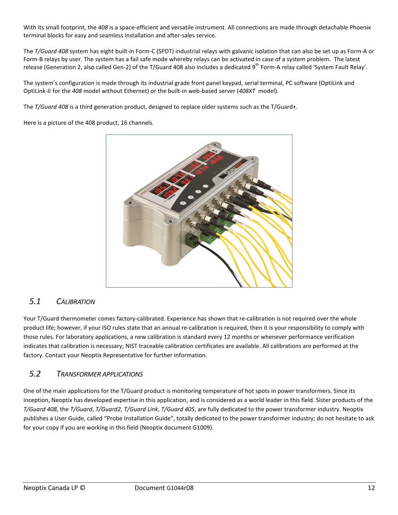
With its small footprint, the 408 is a space-efficient and versatile instrument. All connections are made through detachable Phoenix terminal blocks for easy and seamless installation and after-sales service. The T/Guard 408 system has eight built-in Form-C (SPDT) industrial relays with galvanic isolation that can also be set up as Form-A or Form-B relays by user. The system has a fail safe mode whereby relays can be activated in case of a system problem. The latest release (Generation 2, also called Gen-2) of the T/Guard 408 also includes a dedicated 9th Form-A relay called 'System Fault Relay'. The system’s configuration is made through its industrial grade front panel keypad, serial terminal, PC software (OptiLink and OptiLink-II for the 408 model without Ethernet) or the built-in web-based server (408XT model). The T/Guard 408 is a third generation product, designed to replace older systems such as the T/Guard+. Here is a picture of the 408 product, 16 channels.
5.1 CALIBRATION
Your T/Guard thermometer comes factory-calibrated. Experience has shown that re-calibration is not required over the whole product life; however, if your ISO rules state that an annual re-calibration is required, then it is your responsibility to comply with those rules. For laboratory applications, a new calibration is standard every 12 months or whenever performance verification indicates that calibration is necessary; NIST traceable calibration certificates are available. All calibrations are performed at the factory. Contact your Neoptix Representative for further information.
5.2 TRANSFORMER APPLICATIONS
One of the main applications for the T/Guard product is monitoring temperature of hot spots in power transformers. Since its inception, Neoptix has developed expertise in this application, and is considered as a world leader in this field. Sister products of the T/Guard 408, the T/Guard, T/Guard2, T/Guard Link, T/Guard 405, are fully dedicated to the power transformer industry. Neoptix publishes a User Guide, called “Probe Installation Guide”, totally dedicated to the power transformer industry; do not hesitate to ask for your copy if you are working in this field (Neoptix document G1009).
Neoptix Canada LP © Document G1044r08 13
6 INSTALLATION OF THE T/GUARD 408
Information: Neoptix also published a Quick Startup Guide for the 408; you are encouraged to read this short document first. Reference document number is G1027Rxx
This chapter provides an overview of both the electrical connections and of the fiber connection to a T/Guard 408 system.
6.1 MECHANICAL INSTALLATION
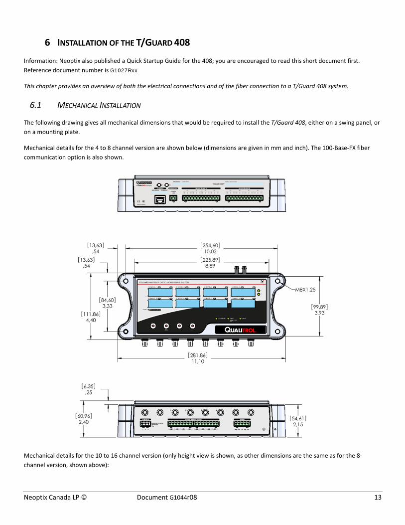
The following drawing gives all mechanical dimensions that would be required to install the T/Guard 408, either on a swing panel, or on a mounting plate.
Mechanical details for the 4 to 8 channel version are shown below (dimensions are given in mm and inch). The 100-Base-FX fiber communication option is also shown.
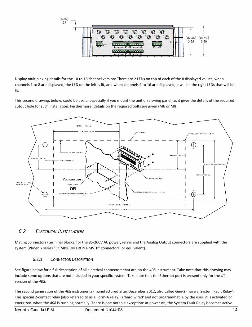
Mechanical details for the 10 to 16 channel version (only height view is shown, as other dimensions are the same as for the 8-channel version, shown above):
Neoptix Canada LP © Document G1044r08 14
Display multiplexing details for the 10 to 16 channel version: There are 2 LEDs on top of each of the 8 displayed values; when channels 1 to 8 are displayed, the LED on the left is lit, and when channels 9 to 16 are displayed, it will be the right LEDs that will be lit.
This second drawing, below, could be useful especially if you mount the unit on a swing panel, as it gives the details of the required cutout hole for such installation. Furthermore, details on the required bolts are given (M6 or M8).
6.2 ELECTRICAL INSTALLATION
Mating connectors (terminal blocks) for the 85-260V AC power, relays and the Analog Output connectors are supplied with the system (Phoenix series “COMBICON FRONT-MSTB” connectors, or equivalent).
6.2.1 CONNECTOR DESCRIPTION
See figure below for a full description of all electrical connectors that are on the 408 instrument. Take note that this drawing may include some options that are not included in your specific system. Take note that the Ethernet port is present only for the XT version of the 408.
The second generation of the 408 instruments (manufactured after December 2012, also called Gen-2) have a 'System Fault Relay'. This special 2-contact relay (also referred to as a Form-A relay) is 'hard wired' and not programmable by the user; it is activated or energized when the 408 is running normally. There is one notable exception: at power on, the System Fault Relay becomes active
Neoptix Canada LP © Document G1044r08 15
only after a period of about 25 seconds, which corresponds to the time period it takes for the 408 internal electronic to become responsive; if this is not acceptable for your installation, then you should think about using a time delay relay in series with the 408 System Fault Relay. Also, any reboot of the 408 instrument will generate a fault that will last about 10 seconds.
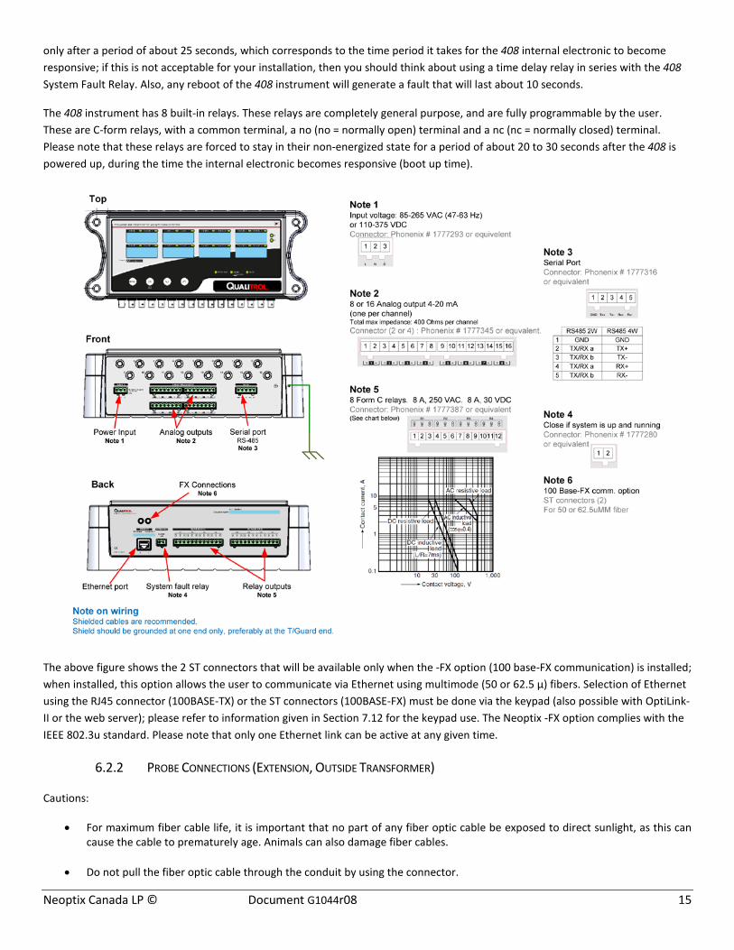
The 408 instrument has 8 built-in relays. These relays are completely general purpose, and are fully programmable by the user. These are C-form relays, with a common terminal, a no (no = normally open) terminal and a nc (nc = normally closed) terminal. Please note that these relays are forced to stay in their non-energized state for a period of about 20 to 30 seconds after the 408 is powered up, during the time the internal electronic becomes responsive (boot up time).
The above figure shows the 2 ST connectors that will be available only when the -FX option (100 base-FX communication) is installed; when installed, this option allows the user to communicate via Ethernet using multimode (50 or 62.5 µ) fibers. Selection of Ethernet using the RJ45 connector (100BASE-TX) or the ST connectors (100BASE-FX) must be done via the keypad (also possible with OptiLink-II or the web server); please refer to information given in Section 7.12 for the keypad use. The Neoptix -FX option complies with the IEEE 802.3u standard. Please note that only one Ethernet link can be active at any given time.
6.2.2 PROBE CONNECTIONS (EXTENSION, OUTSIDE TRANSFORMER)
Cautions:
• For maximum fiber cable life, it is important that no part of any fiber optic cable be exposed to direct sunlight, as this can cause the cable to prematurely age. Animals can also damage fiber cables.
• Do not pull the fiber optic cable through the conduit by using the connector.
Neoptix Canada LP © Document G1044r08 16
• When pulling the fiber optic cable through junction boxes, do not bend the cable less than 25mm (1 inch) radius. Oversized
junction boxes are preferred.
• When pulling the fiber optic cable through a conduit, make sure the red or transparent PVC caps are covering the cable ends.
• The connector ends must be cleaned prior to final connection to remove debris that may have collected during installation.
Debris can block the passage of light down the fiber. To avoid this, please follow the following procedure:
o Use optic-grade wipes and optic grade 99% isopropyl alcohol OR Optic Prep pads.
o Gently wipe the ferrule (and especially the end) in a circular motion
o Allow 10 seconds for the alcohol to evaporate.
Warning: Make sure all unused connector inputs are blocked with dust caps, to prevent any spurious light from entering the thermometer, as this can cause false temperature readings on other channels.
Align the “key” on the connector with the slot on the mating sleeve, slide connector into sleeve and gently rotate the connector body while pushing towards the mating sleeve until the “keys” on the mating sleeve slide into place. This is similar to a bayonet or BNC type connector. To install external fiber optic extension cables, follow this procedure:
1. Make sure the red or clear-colored caps supplied with the cables are installed at each end of each cable, and this for the whole installation process.
2. Tape the pull wire at least 15 cm of the outside fiber optic cable, and then pull the cable through the conduit.
3. Connect all cables to the T/Guard 408 system and at the transformer tank interface.
4. Store all excess fiber optic cables in 25 cm (or more) diameter loops inside the T/Guard 408 enclosure.
To ease installation, the Neoptix extension cables are fitted with user-writable sleeves (one at each end) that can be used to help identify the extension cables; this is useful to identify “which cable is which” once many have been installed in the same conduit. Warning: Do not cross-connect extension cords; this may compromise your system behavior! For more information, please refer the Neoptix ‘Probe Installation Guide’, document #g1009; to get a copy, please ask your Neoptix representative.
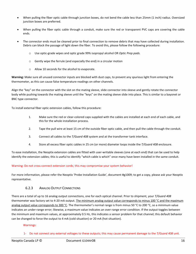
6.2.3 ANALOG OUTPUT CONNECTIONS
There are a total of up to 16 analog output connections, one for each optical channel. Prior to shipment, your T/Guard 408 thermometer was factory set to 4-20 mA output. The minimum analog output value corresponds to minus 100 °C and the maximum analog output value corresponds to 300 °C. The thermometer’s normal range is from minus 50 °C to 200 °C, so a minimum value indicates an under-range error; likewise, a maximum value indicates an over-range error condition. If the output toggles between the minimum and maximum values, at approximately 0.5 Hz, this indicates a sensor problem for that channel; this default behavior can be changed to force the output to 4 mA (cold situation) or 20 mA (hot situation).
Warnings:
1- Do not connect any external voltages to these outputs; this may cause permanent damage to the T/Guard 408 unit.
Neoptix Canada LP © Document G1044r08 17
2- Avoid shorting together output leads together, as this may destroy the electronic drivers inside the unit.
It is possible to change the Zero and Span from their default -100 oC and 400 oC. With the 408, you can also use either the OptiLink or the OptiLink-II programs to set these parameters; with the 408XT version, you can also use the web server pages.
When using long wires to the analog outputs (4-20mA), it is recommended to use shielded twisted pairs, size AWG 24 or 22. The shield should be grounded at one end only, preferably at the T/Guard 408 end.
When the instrument is powered up, the analog outputs are forced to stay at their minimum values (4mA) until the internal electronic is up and running, which takes about 25 seconds.
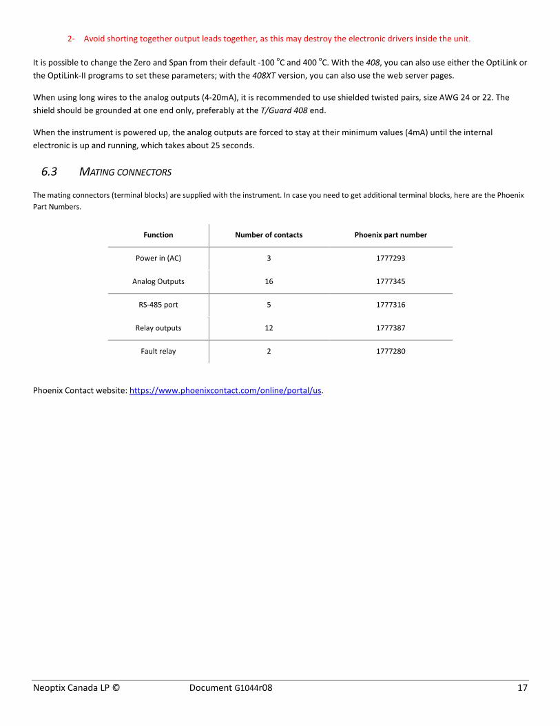
6.3 MATING CONNECTORS
The mating connectors (terminal blocks) are supplied with the instrument. In case you need to get additional terminal blocks, here are the Phoenix Part Numbers.
Function Number of contacts Phoenix part number
Power in (AC) 3 1777293
Analog Outputs 16 1777345
RS-485 port 5 1777316
Relay outputs 12 1777387
Fault relay 2 1777280
Phoenix Contact website: https://www.phoenixcontact.com/online/portal/us.

Neoptix Canada LP © Document G1044r08 18
7 USING THE KEYPAD MENUS
Before we describe the use of the 4-button keypad, you need to realize that Neoptix offers the following tools to allow you to enter the various parameters that you will need to enter into your 408 before it is ready for use. The keypad is only one of many, and it is probably the most difficult tool of all the tools. In a nutshell, the following are available, starting with the friendliest tool:
• The web server; this option is not available for the 408, but only for the 408XT • The OptiLink-II software tool. This new software tool can make the task of parameter entry much easier; you are highly
encouraged to use it; see chapter 9 for a complete description. Contact Neoptix to get the latest version; downloadable from the Neoptix website (www.neoptix.com).
• The keypad, described in this chapter. • This Chapter deals with the basic software operation of your T/Guard 408 instrument, through its main LED display and 4-
button keypad. Again, if you are using the T/Guard 408XT instrument, with an Ethernet connection, it is highly suggested that you read the Quick Start Guide (G1027Rxx), to learn how to connect to the Ethernet.
The T/Guard 408 has four buttons under its display, from left to right they are: • The MENU button, the OK button, the DOWN arrow button and the UP arrow button.
With these buttons, you will be able to directly obtain and set various device configuration settings. Here is how.
The OK button can also be used to acknowledge (and clear) all un-acknowledged alarms, as indicated by the red LED. Note that an alarm acknowledge has no effect on the information stored in the event log file.
7.1 THE MAIN DISPLAY MENU
Before beginning, please note that any operation begun on the LED menus will time out and return to displaying temperatures after about 30 seconds, so if you accidentally make a mistake, just wait a few moments and you will be able to try again with no harm done. It is also important to note that the default settings of the device are normally just fine for most cases and are based on engineer recommendations, so you should modify settings only if you are sure.
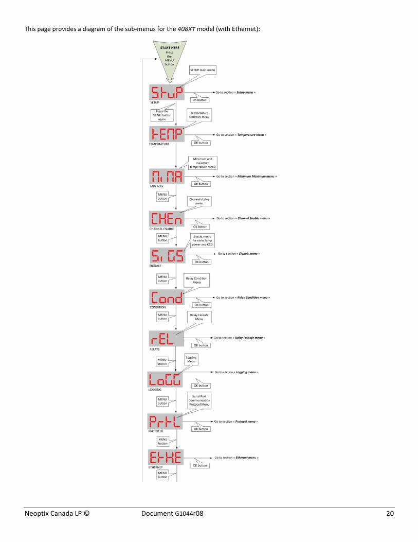
To get started, click on the left-most MENU button. This is the entry point to all the different functionalities provided through the display. The sub-menus for these functionalities are:
• Setup • Temperature • Minimum Maximum Temperatures per channel • Channel Status (Enabled/Disabled) • Signals (Min/Max Ratio, Lamp power, CCD time and power %) • Relay Condition • Relay Failsafe • Logging • Protocol • Ethernet (model 408XT only).
You can cycle through these sub-menu selections and back again to the temperature display by clicking on the MENU button repeatedly.
If you enter one of the sub-menus, you can always get out of them without making any permanent changes by clicking the MENU button.

Neoptix Canada LP © Document G1044r08 19
This page provides a diagram of the sub-menus for the 408 model (no Ethernet):
Neoptix Canada LP © Document G1044r08 20
This page provides a diagram of the sub-menus for the 408XT model (with Ethernet):

Neoptix Canada LP © Document G1044r08 21
7.2 THE SETUP MENU
This menu provides information about:
• the device’s internal software version; there is nothing to set here, this is information that would be useful only if you were to place a support call;
• whether there is a second calibration of temperatures; this depends on whether the fiber optic probes are legacy (Nortech Fibronic probes), in which case: “enabled”, or not: “disabled”;
• the number of times a temperature is held internally before displaying “not available”; normally there is almost never any need to change this value (for transformer applications, 5 is recommended);
• whether Wtune is enabled or not (for transformer applications, this should be enabled) (maximum sensitivity is obtained with Wtune enabled, at the expense of a slower acquisition speed);
• whether temperatures are displayed in degrees Fahrenheit or Celsius;
• whether the serial port is set for half or full duplex (this can be controlled by software, but must match associated hardware and wiring adjustments);
• the interval of time (for T/Guard 408 devices with more than 8 channels) between the presentation of channels 1 to 8 (bank 1) on the display and the presentation of the remaining channels (bank 2), from 1 to 8 seconds;
• whether the serial communication is functioning properly (visual test using a LED). When activated, the “Alarm” LED will flash temporarily when ASCII characters are received or sent on the RS-485 serial port. This will work with all serial protocols (ASCII, Modbus, DNP 3 and IEC 61870). This feature is disabled automatically when the electronic reboots.
If you change the temperature unit while the device is set to save temperatures to a log file, then a new log file will be started with the new correct unit and the old log file will be archived. This ensures the correct temperature unit is displayed in the log headers at all times.
Either the current log file or the archived log file(s) can be retrieved by file download.
Here are schematics of the various menus (next page):

Neoptix Canada LP © Document G1044r08 22
Neoptix Canada LP © Document G1044r08 23
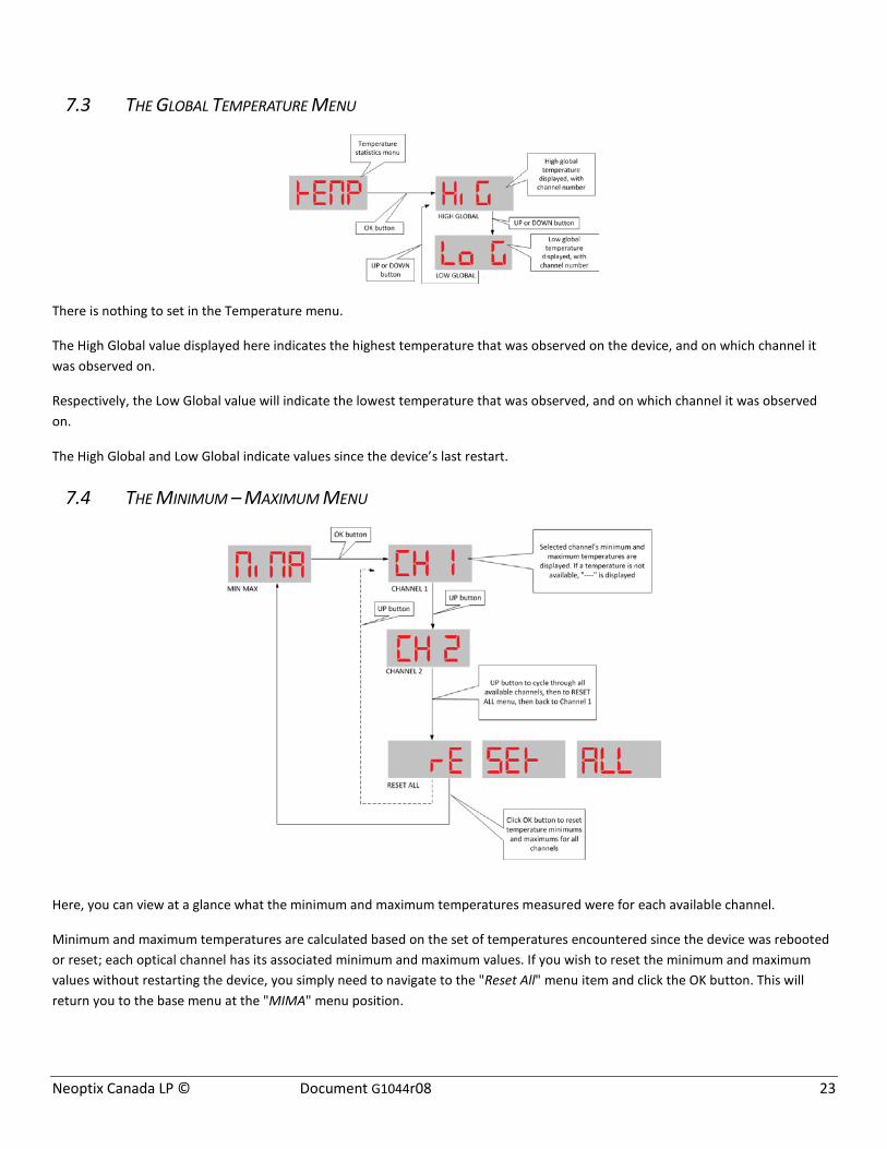
7.3 THE GLOBAL TEMPERATURE MENU
There is nothing to set in the Temperature menu.
The High Global value displayed here indicates the highest temperature that was observed on the device, and on which channel it was observed on.
Respectively, the Low Global value will indicate the lowest temperature that was observed, and on which channel it was observed on.
The High Global and Low Global indicate values since the device’s last restart.
7.4 THE MINIMUM – MAXIMUM MENU
Here, you can view at a glance what the minimum and maximum temperatures measured were for each available channel.
Minimum and maximum temperatures are calculated based on the set of temperatures encountered since the device was rebooted or reset; each optical channel has its associated minimum and maximum values. If you wish to reset the minimum and maximum values without restarting the device, you simply need to navigate to the "Reset All" menu item and click the OK button. This will return you to the base menu at the "MIMA" menu position.
Neoptix Canada LP © Document G1044r08 24
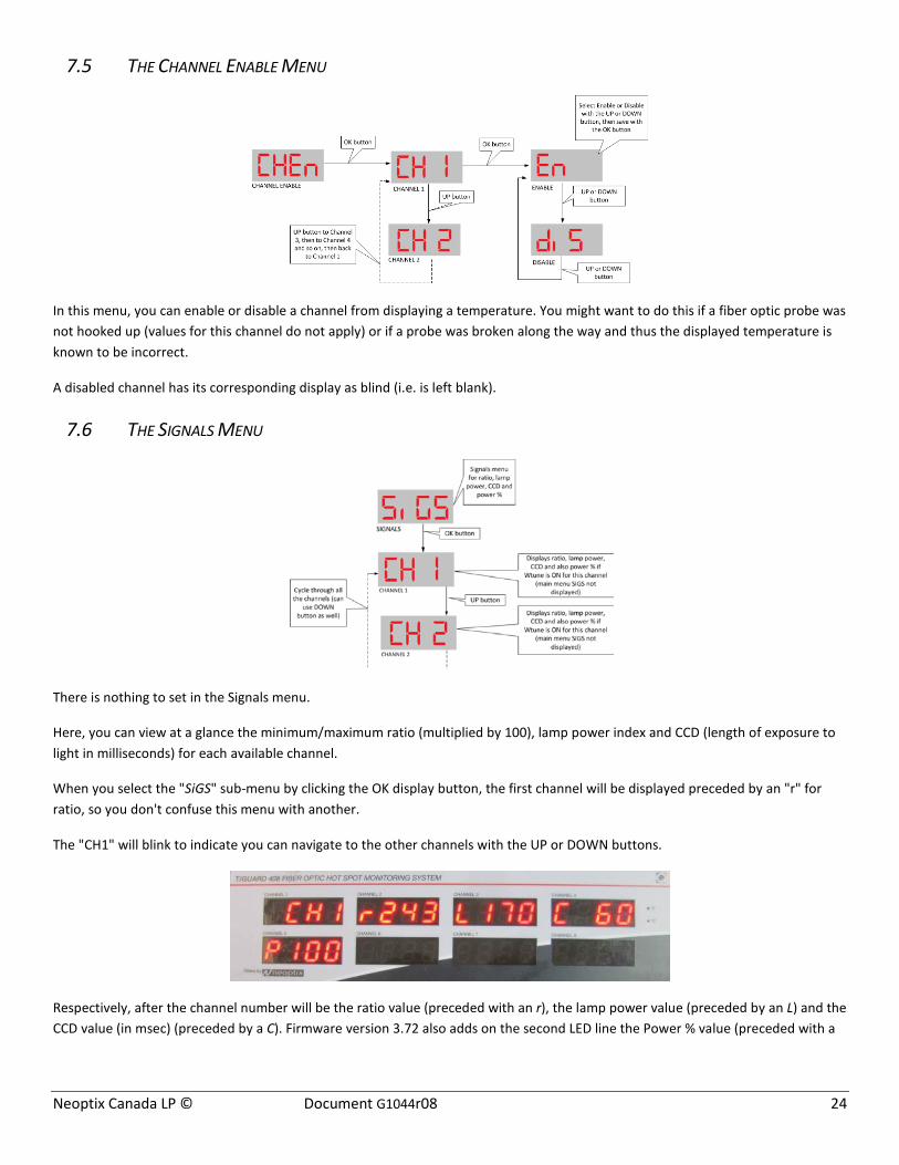
7.5 THE CHANNEL ENABLE MENU
In this menu, you can enable or disable a channel from displaying a temperature. You might want to do this if a fiber optic probe was not hooked up (values for this channel do not apply) or if a probe was broken along the way and thus the displayed temperature is known to be incorrect.
A disabled channel has its corresponding display as blind (i.e. is left blank).
7.6 THE SIGNALS MENU
There is nothing to set in the Signals menu.
Here, you can view at a glance the minimum/maximum ratio (multiplied by 100), lamp power index and CCD (length of exposure to light in milliseconds) for each available channel.
When you select the "SiGS" sub-menu by clicking the OK display button, the first channel will be displayed preceded by an "r" for ratio, so you don't confuse this menu with another.
The "CH1" will blink to indicate you can navigate to the other channels with the UP or DOWN buttons.
Respectively, after the channel number will be the ratio value (preceded with an r), the lamp power value (preceded by an L) and the CCD value (in msec) (preceded by a C). Firmware version 3.72 also adds on the second LED line the Power % value (preceded with a

Neoptix Canada LP © Document G1044r08 25
P), ranging from 0 to 100%; this parameter is a sort of amalgamation that simplifies the interpretation of optical signal strength3. See Section 12.4.1 for a detailed discussion regarding the interpretation of these parameters.
Hint: If the power percent value is not displayed (“P 100” in above example), this means that the parameter “wtune” is not currently enabled. Refer to Section 7.2 to enable wtune.
At any time, you can exit the SIGNALS menu by clicking the left-most MENU button.
3 For oil-filled power transformer application, experience has shown that this reading be at least 100% for a probe alone, and a minimum of 65% when testing a probe connected to OFT feedthrough and extension cable (at room temperature).

Neoptix Canada LP © Document G1044r08 26
7.7 THE RELAY CONDITION MENU

Neoptix Canada LP © Document G1044r08 27
The Relay Condition menu is the most complex of the menus, with a logic path five-level deep. This allows you to set conditions that will trigger a relay, and by extension an automated process, when the desired conditions are met.
An example of a relay condition could be something like, “if channel number X’s temperature rises above temperature Y, then set off relay number Z”, where X, Y and Z are all numeric values than can be chosen and set. Here “above” means the same as “greater than”.
The system support up to 128 settable conditions, each one can be enabled or disabled. Because setting all these conditions on the display could become quite a chore, there are alternatives: more user-friendly ways are provided by the T/Guard 408 to set relay conditions. The 408XT model also offers a third alternative: a web interface where conditions can be set.
Each relay condition can be either logged and each condition can be flagged as an alarm condition. There are three possible combinations of event logging and alarm: DISABLED (no logging, no alarm); ENABLED (with logging, but no alarm) and ALARM (with logging and alarm). An alarm is always logged.
7.8 THE RELAY FAILSAFE MENU
This menu will allow you to set whether a given relay is normally open or normally closed.
It can be used for example in combination with relay condition settings to turn something either on or off when a condition is reached.
7.9 THE LOGGING MENU
By default out of the box, the T/Guard 408 logs once every 10 minutes.
To reduce internal file I/O on the internal disk media, it is possible to turn off logging completely using this menu here.
In general, it is recommended to leave the data logging on using a logging rate of 10 minutes or more (except for heatrun tests (temperature rise tests), where 1 or 2 minute intervals are recommended).
Please note that if you reduce the logging rate to less than once per minute, and the device is restarted, that logging rate will automatically be reset to one per minute by design. This is because a logging rate this frequent is considered an extraordinary value, probably only to be used in the case of an emergency and undesirable in the long run (after the emergency is over).

Neoptix Canada LP © Document G1044r08 28
7.10 THE PROTOCOL MENU (SERIAL)
If you have purchased the serial protocol package, the following protocols will be available to you (the Modbus and Neoptix ASCII protocols protocol are always included with the basic instrument package; however, this menu allows configuring them):
o Neoptix ASCII protocol (required for OptiLink, OptiLink-II and HyperTerminal or equivalent)
o Modbus
o DNP 3.0
o And IEC 60870-5-101.

Neoptix Canada LP © Document G1044r08 29
This menu is exclusively for protocols that communicate through the serial port.
There are some restrictions on the combination of parity and stop bits that can be set depending on the protocol you want to use; illegal combinations of baud rate, stop and parity bits are not selectable.
Warning: Switching from one protocol to another will render a currently-connected client useless you when you disconnect it and reconnect again. Disconnecting an application can be confusing, so be careful when you make changes here.
Warning: Your external wiring can be done in half-duplex (2 wires) or full duplex (4 wires); in all cases, make sure the software setting is matching your hardware. For the 408, please refer to section 7.2.
Neoptix has published a separate guide on protocols, # g1030; do not hesitate to ask for your copy.
7.10.1 NEOPTIX ASCII PROTOCOL
For backward compatibility with other Neoptix products, the Neoptix ASCII protocol is at baud rate 9600, Parity None, Stop Bits 1. Although this baud rate can be tweaked at run time to make a file download or upload faster (see Troubleshooting section for a how-to concerning this), such a change is strictly temporary and non-persistent: the baud rate for this protocol is always set to 9600 at boot time. This selection is necessary to use software such as OptiLink, OptiLink-II, HyperTerminal and Tera Term.
7.10.2 MODBUS PROTOCOL
For Modbus, baud, parity and stop bits settings are configurable. Please note however that as per the protocol’s specifications, only some combinations of these settings are allowed:
• Parity even, 1 stop bit • Parity odd, 2 stop bits • Parity none, 2 stop bits (1 stop bit is also accepted, but this in principle does not comply with the standard).
The Modbus protocol also has an Address ID value (also called Node address) that indicates the device’s position, i.e. where it is daisy chained (or networked) with other devices. Valid ID addresses are from 1 to 247 (up to 255 is tolerated).
Please refer to “APPENDIX D - Modbus communication protocol”, chapter 13, for the complete reference regarding this protocol. Document G1030, Smart Protocol Reference Guide, can also be a very useful reference document; do not hesitate to ask you copy from Neoptix.
7.10.3 DNP 3.0 PROTOCOL
For DNP 3.0, the baud rate is modifiable. Parity is fixed at None and Stop bit is fixed at 1 as per protocol specifications. Master station address by default is 65500 and secondary station address (or 408 slave address id) by default is 1. It is recommended to keep these default values. If you need to change them, however, it is possible through the Labels and Interfaces web page on the 408XT model or (on all models) through the following Neoptix protocol serial commands:
master:XXXXX .. Define DNP 3.0 master station address (normally 65500)
second:XXXXX .. Define DNP 3.0 secondary (slave, the 408 here) station address (normally 1)
7.10.4 IEC 60870-5-101 PROTOCOL
For IEC 60870, baud rate and address id are modifiable. Parity is fixed at Even and Stop bit is fixed at 1 as per protocol specifications.

Neoptix Canada LP © Document G1044r08 30
7.11 THE TIME MENU
The time menu can be used to initialize the 408 clock. It can be used to set the time zone, the date and the time. Please note that if the NTP server is active, the Ethernet will overwrite any date and time entries that you may have made here.
7.12 THE ETHERNET MENU (FOR 408XT MODEL ONLY)
Remember that you need a live Ethernet connection for the following to function properly. The network connection is normally established by the device at boot time, right after the start of the main temperature acquisition and display program.
The blinking IP submenu immediately displays the current IP address, alternating with “EtHE AddrESS” (Ethernet address).
From this submenu, click the UP or DOWN button to go to the IP submenu. The currently selected configuration will also be displayed: i.e. either dynamic DHCP or the Static IP preset of 10.0.0.4.
The DHCP submenu is intended to help you to resolve networking difficulties with the device, the most common being a badly configured static IP address which makes the device unresponsive over the network. This could be caused by a bad gateway setting or an IP address out of allowed range set on the device. If “DHCP no connect” is displayed, check your cabling first!
The DHCP submenu allows you to either:

Neoptix Canada LP © Document G1044r08 31
• reset an incorrect static network setting back to dynamic DHCP, or • configure the device to the factory default preset static IP address that will allow you to connect a computer or notebook
directly to the device using a special cable, in the case where no DHCP server is present. This preset address is: IP address: 10.0.0.4 Netmask: 255.255.255.0 Gateway: 10.0.0.1
If you do not like these settings, you must first connect using these default values, then go to the web pages and enter the addresses that you want.
If your 408 is fitted with the FX option (100 Base-FX), this menu allows you to choice between the RJ45 copper Ethernet or the FX fiber Ethernet; you should select the one you intend to use. Please note that if you are connected to one type, the other one is automatically disabled.
A change in IP address or in the Ethernet port selection will force a system reboot.

Neoptix Canada LP © Document G1044r08 32
8 USING THE WEB INTERFACE (408XT MODEL)
8.1 OVERVIEW
The web application provides the same functionalities as through the serial port, and more, and the Ethernet connection is tens of times faster on a regular network than through the serial port.
8.1.1 USER MANAGEMENT
The T/Guard 408XT allows the creation of up to 10 users, each with their own login and password to the web application, with either a “guest” role or an “administrator user” role. An “admin” user can update configurations and a “guest” user can only view data. This convenience allows:
• Providing temporary limited access to the device various personnel without having to vehicle sensitive passwords; a new user can be set up as a guest quickly and the login can be deleted a short time later.
• Distributing responsibility between more than one manager while maintaining basic security;
8.1.2 WEB SESSIONS
A web session is unique to a single user on a single computer on a single browser. If there is no action for 15 minutes, the web session times out and the user will need to log on again to resume. As many as 25 concurrent sessions can be open simultaneously; each session can have its own language selection; however a new session always starts in English.
8.1.3 DUPLICATING CUSTOM CONFIGURATIONS BETWEEN T/GUARD 408 DEVICES
No more taking notes and having to remember what you configured on an identical device a few months ago. On the T/Guard 408, it’s as easy as downloading a file from one device and uploading the downloaded file to a second device, then restarting the second device. See Section 8.7.13.
Temperature units, relay conditions, second calibration, offsets and many other preferences can be instantly carried over this way from one T/Guard 408 to the next for zero rework.
8.2 NETWORKING THE T/GUARD 408 DEVICE
This section deals with the initial networking setup of your new T/Guard 408XT instrument. Your new T/Guard 408 comes calibrated and ready to use. Plug in the Ethernet cable (which is yellow in the photo below) decisively in order to hear an audible click. Next, connect the provided power cable. The unit does not have a power switch button, and should boot immediately. The display should look like the image below in less than 30 seconds:
Out of the box, the device is configured to use static IP address 10.0.0.4, Netmask 255.255.255.0 and Gateway 10.0.0.1 so that you can connect your T/Guard 408 directly to a computer, either a PC or a Mac, using the Ethernet link. This approach is the Neoptix
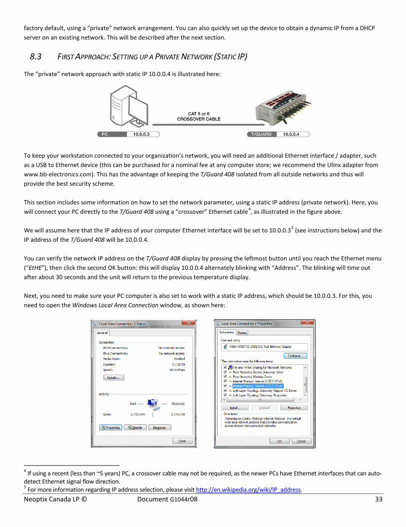
Neoptix Canada LP © Document G1044r08 33
factory default, using a “private” network arrangement. You can also quickly set up the device to obtain a dynamic IP from a DHCP server on an existing network. This will be described after the next section.
8.3 FIRST APPROACH: SETTING UP A PRIVATE NETWORK (STATIC IP)
The “private” network approach with static IP 10.0.0.4 is illustrated here:
To keep your workstation connected to your organization’s network, you will need an additional Ethernet interface / adapter, such as a USB to Ethernet device (this can be purchased for a nominal fee at any computer store; we recommend the Ulinx adapter from www.bb-electronics.com). This has the advantage of keeping the T/Guard 408 isolated from all outside networks and thus will provide the best security scheme. This section includes some information on how to set the network parameter, using a static IP address (private network). Here, you will connect your PC directly to the T/Guard 408 using a “crossover” Ethernet cable4, as illustrated in the figure above. We will assume here that the IP address of your computer Ethernet interface will be set to 10.0.0.35 (see instructions below) and the IP address of the T/Guard 408 will be 10.0.0.4. You can verify the network IP address on the T/Guard 408 display by pressing the leftmost button until you reach the Ethernet menu (“EtHE”), then click the second OK button: this will display 10.0.0.4 alternately blinking with “Address”. The blinking will time out after about 30 seconds and the unit will return to the previous temperature display. Next, you need to make sure your PC computer is also set to work with a static IP address, which should be 10.0.0.3. For this, you need to open the Windows Local Area Connection window, as shown here:
4 If using a recent (less than ~5 years) PC, a crossover cable may not be required, as the newer PCs have Ethernet interfaces that can auto-detect Ethernet signal flow direction. 5 For more information regarding IP address selection, please visit http://en.wikipedia.org/wiki/IP_address.

Neoptix Canada LP © Document G1044r08 34
And then open the Properties window. Select “Internet Protocol Version 4” and click the Properties button; you should get the following window (left). Select the “Use the following IP address” button, and enter the information as shown in the figure on the right, below:
Alternatively, you can also enter a fixed IP address using the “Alternate Configuration” tab shown in the above left picture. By doing so, it would be easier to switch back and forth between a DHCP enabled configuration (such as would be required in an office environment) and a fixed IP configuration (such as would be required to directly interface with a T/Guard 408 system). This is illustrated here:
Exit all open configuration windows by clicking the OK buttons. If you have problems connecting to the Ethernet, or to understand the parameters in the red box above, you should contact your Local Network Administrator for help. Alternatively, you can also work with a dynamic IP address (DHCP server), even if you are connected directly to your T/Guard 408; this can be done by installing a shareware in your PC, which would act as a private DHCP server. Neoptix has successfully used the “DHCP Server for Windows” software, which can be downloaded from http://www.dhcpserver.de/dhcpsrv.htm6. The readme.txt file gives instructions on how to use this very useful program (in particular how to set a range of searchable IP addresses, with the IPPOOL_1 variable).
6 Do not run as a service unless you what to use this configuration as a permanent installation.

Neoptix Canada LP © Document G1044r08 35
8.4 WORKING WITH THE INTERNET BROWSER (FIXED IP ADDRESS)
Start your compatible7 web browser8. In the address bar, enter “10.0.0.4”9. The first page you will see is the login page, as follows:
Help suggestion: You may have to reboot your PC computer so a recently connected 408XT instrument will be “detected” your Ethernet connection; So, if you believe all your settings are correct, and your PC do not “see” your 408XT instrument, it is suggested to reboot your computer. Using the web interface, you will be able to refine your static network settings if you wish.
8.5 SECOND APPROACH: SETTING UP DYNAMIC ADDRESS (DHCP SERVER)
This assumes you are familiar with networking computers, and that you have a DHCP server (such as a router) already running on the network you want to connect the T/Guard 408 to. Here are the quick steps:
• On the display of the T/Guard 408, click the leftmost MENU button until you reach the Ethernet menu (“EtHE”);
• Click the second OK button once, the blinking “Address” submenu will be displayed along with the current IP address:
7 The following browsers are supported:
• Mozilla Firefox version 4.0 and above (recommended). • Microsoft Internet Explorer version 7 and above.
o Note on Explorer version 10: Some functionalities (e.g. file upload) will only work when using firmware version 3.92 and above. Contact Neoptix if you need to upgrade your instrument.
• Google Chrome version 16 and above. • Apple Safari 5 and above.
8 A note concerning Microsoft Internet Explorer: Recent versions of Internet Explorer (versions 9 and 10 in particular) may display some pages in a distorted way; this is due to compatibility issues in Explorer. This can be solved through a setting in Explorer, using “Compatibility view settings”.
9 The various screen pictures that are included in this guide may show different IP addresses in the address bar; this inconsistency is due to the fact that these screenshots have been done at different moments using different settings.
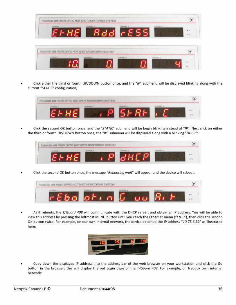
Neoptix Canada LP © Document G1044r08 36
• Click either the third or fourth UP/DOWN button once, and the “IP” submenu will be displayed blinking along with the current “STATIC” configuration;
• Click the second OK button once, and the “STATIC” submenu will be begin blinking instead of “IP”. Next click on either the third or fourth UP/DOWN button once, the “IP” submenu will be displayed along with a blinking “DHCP”:
• Click the second OK button once, the message “Rebooting wait” will appear and the device will reboot:
• As it reboots, the T/Guard 408 will communicate with the DHCP server, and obtain an IP address. You will be able to view this address by pressing the leftmost MENU button until you reach the Ethernet menu (“EtHE”), then click the second OK button twice. For example, on our own internal network, the device obtained the IP address “10.75.6.59” as illustrated here:
• Copy down the displayed IP address into the address bar of the web browser on your workstation and click the Go button in the browser: this will display the red Login page of the T/Guard 408. For example, on Neoptix own internal network:

Neoptix Canada LP © Document G1044r08 37
8.6 THE T/GUARD 408XT WEB APPLICATION
8.6.1 NOTE CONCERNING THE WEB BROWSER CACHE
All web browsers are not made the same and do not behave identically by default.
Although every effort has been made in the T/Guard 408 web application to prevent your web browser from storing (also called “caching”) information which can quickly become outdated or confusing by sending precise directives to your browser, certain modern web browsers simply ignore or override these directives in favor of user-defined settings by default.
In addition, the behavior of a web browser will vary from one version to the next because of divergent design and security considerations, or contradictory interpretations of new technology specifications.
Caching can lead to unpredictable results, especially if working with more than one T/Guard 408 devices on your network at the same time, different only in MAC addresses and IP addresses.
For this reason, it is important for you to set your web browser from preventing caching. There is a “wikihow” web site which explains how to do this for all major browsers at:
http://www.wikihow.com/Clear-Your-Browser%27s-Cache
Sometimes because of aggressive caching, even refreshing a web page does not work. Here are the steps to prevent caching on the Windows 7 English versions of Firefox, Internet Explorer and Chrome.
For Internet Explorer 8
Overall, Internet Explorer is a browser that is eager to cache data by default.
1. Once your browser is open, click the Tools menu. Or, optionally you may simply press Ctrl+Shift+Delete to open the Delete Browsing History window (and skip step 2);
2. Click on Delete Browsing History... 3. Select Temporary Internet Files. 4. Click the Delete button near the bottom of the window to delete your temporary files (i.e. clear your cache). 5. Click the Tools menu and go to Internet Options and to the Advanced tab. Click to check the box next to the Empty
Temporary Internet Files folder when browser is closed option (in the section labeled Security). Click OK. This will delete everything except cookies. Note: IE8 has a "feature" which retains some cookies even after you clear your cache if you do not UNCHECK the "Preserve Favorites Website Data.", so uncheck this as well.
For Firefox 13 and above
1. Go to menu Tools > Options > Advanced > Network tab
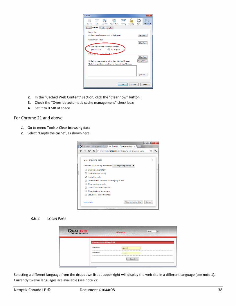
Neoptix Canada LP © Document G1044r08 38
2. In the “Cached Web Content” section, click the “Clear now” button ; 3. Check the “Override automatic cache management” check box; 4. Set it to 0 MB of space.
For Chrome 21 and above
1. Go to menu Tools > Clear browsing data 2. Select “Empty the cache”, as shown here:
8.6.2 LOGIN PAGE
Selecting a different language from the dropdown list at upper right will display the web site in a different language (see note 1). Currently twelve languages are available (see note 2):

Neoptix Canada LP © Document G1044r08 39
Notes:
1- Please note that the language selection is not stored in the 408 instrument; instead it always reverts to English when a new web session is open by a user. For example, if 2 users are concurrently connected to the same 408 instrument, each user can select the language of his or her choice.
2- If you get characters such as follows: , this indicates that your browser is mixed up while
dealing with different character encoding. With Internet Explorer, this problem can usually be corrected by right clicking anywhere in your web page, then select \“Encoding\”, and then \“Unicode (UTF-8)\”; with Firefox, select \“Firefox\” (lower top corner), then \“Web Developer\”, then \“Character Encoding\” and then \“Unicode (UTF-8)\”; with Google Chrome,
select , then \“Tools\”, then \“Encoding\” and then \“Unicode (UTF-8)\”. This should solve this problem.
It is required to log on to view data remotely. Out of the factory, two users are programmed by default:
1- Administrator level (user name “neoptix”, password “pass”) 2- Viewer level (user name “guest”, password “guest”)
It is very important to change the admin user name and password on first use; you will be reminded to do so every time you log in; however, there is no obligation to change any user name or password.
The guest user can be deleted outright, if you wish.
The regular user programmed by default into the device cannot be deleted and cannot be modified into a guest account.
The T/Guard 408 does not currently support single sign-on networking (through LDAP) or digital encryption certificates.
The word “Alarms” will flash in all windows when any unacknowledged alarms are active. You can clear this by either acknowledging any pending alarms, or by disabling this feature in the “Alarm management” window (see Section 8.7.26).
8.6.3 CONFIGURABLE COLORED DOTS IN THE WEB PAGE HEADERS

Neoptix Canada LP © Document G1044r08 40
When there are several T/Guard 408XT devices on your network and they each need to be configured, it could get rather confusing because all the web applications look identical.
To help differentiate between devices, configurable colored dots were added to the web application. To modify the color of the dots on all the pages of one device, a user with administrative privileges simply clicks on one of the dots and a color picker control appears:
Next, select a new color by clicking on it in the control. To finalize a selection and dismiss the control, click outside the color picker. You will be prompted to confirm the selection:
If you choose to keep the new color, it will become permanent even after the device reboots.
This way, each T/Guard 408XT on your network can be “color coded”, conveniently preventing all too human mistakes.
A guest user cannot modify the dot colors.
A reset does not affect the dot color either, once again to prevent confusion.
8.7 WEB PAGES FOR AN ADMINISTRATOR USER
8.7.1 T/GUARD 408XT HOME PAGE
This is the start page for the web application.
The screen shots shown below have been done with an 8-channel system. The temperatures are updated live on the web page every few seconds.
There is nothing to configure or modify here.
On this web page, if a channels indicates “---.-“, it means it has no sensors attached or the probe is broken. A channel indicating a blank means it is disabled (none such displayed below, channel 8). The same scheme is used on the LED display menu.
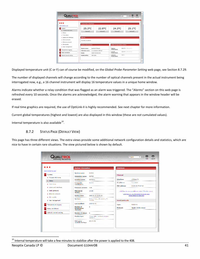
Neoptix Canada LP © Document G1044r08 41
Displayed temperature unit (C or F) can of course be modified, on the Global Probe Parameter Setting web page, see Section 8.7.29.
The number of displayed channels will change according to the number of optical channels present in the actual instrument being interrogated now, e.g., a 16 channel instrument will display 16 temperature values in a unique home window.
Alarms indicate whether a relay condition that was flagged as an alarm was triggered. The “Alarms” section on this web page is refreshed every 10 seconds. Once the alarms are acknowledged, the alarm warning that appears in the window header will be erased.
If real time graphics are required, the use of OptiLink-II is highly recommended. See next chapter for more information.
Current global temperatures (highest and lowest) are also displayed in this window (these are not cumulated values).
Internal temperature is also available10.
8.7.2 STATUS PAGE (DEFAULT VIEW)
This page has three different views. The extra views provide some additional network configuration details and statistics, which are nice to have in certain rare situations. The view pictured below is shown by default.
10 Internal temperature will take a few minutes to stabilize after the power is applied to the 408.

Neoptix Canada LP © Document G1044r08 42
8.7.3 STATUS PAGE (RAW ETHERNET STATS VIEW)
This web page will provide network details in a format very familiar to most computer network administrators.
8.7.4 STATUS PAGE (FORMATTED ETHERNET STATISTICS VIEW)
This web page provides the same basic information as the previous, in a user friendly way. Because information is heavily processed, filtered and re-assembled, this view takes a few extra seconds to load.
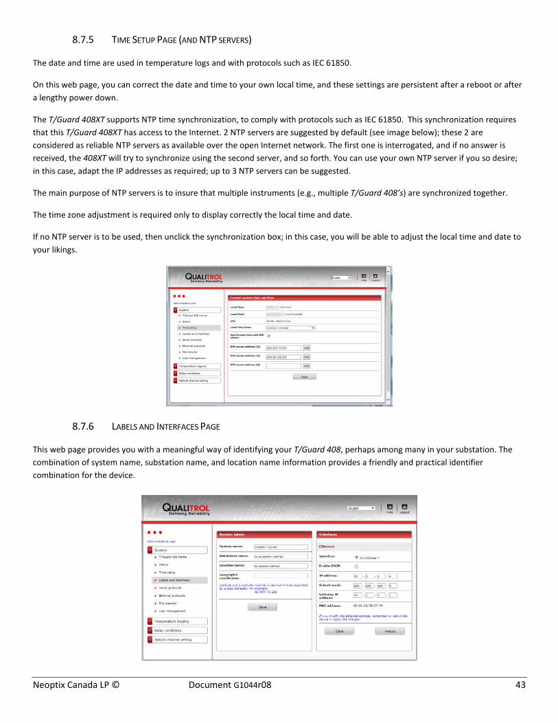
Neoptix Canada LP © Document G1044r08 43
8.7.5 TIME SETUP PAGE (AND NTP SERVERS)
The date and time are used in temperature logs and with protocols such as IEC 61850.
On this web page, you can correct the date and time to your own local time, and these settings are persistent after a reboot or after a lengthy power down.
The T/Guard 408XT supports NTP time synchronization, to comply with protocols such as IEC 61850. This synchronization requires that this T/Guard 408XT has access to the Internet. 2 NTP servers are suggested by default (see image below); these 2 are considered as reliable NTP servers as available over the open Internet network. The first one is interrogated, and if no answer is received, the 408XT will try to synchronize using the second server, and so forth. You can use your own NTP server if you so desire; in this case, adapt the IP addresses as required; up to 3 NTP servers can be suggested.
The main purpose of NTP servers is to insure that multiple instruments (e.g., multiple T/Guard 408’s) are synchronized together.
The time zone adjustment is required only to display correctly the local time and date.
If no NTP server is to be used, then unclick the synchronization box; in this case, you will be able to adjust the local time and date to your likings.
8.7.6 LABELS AND INTERFACES PAGE
This web page provides you with a meaningful way of identifying your T/Guard 408, perhaps among many in your substation. The combination of system name, substation name, and location name information provides a friendly and practical identifier combination for the device.
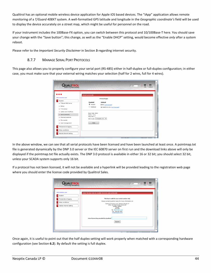
Neoptix Canada LP © Document G1044r08 44
Qualitrol has an optional mobile wireless device application for Apple iOS based devices. The “iApp” application allows remote monitoring of a T/Guard 408XT system. A well-formatted GPS latitude and longitude in the Geographic coordinate’s field will be used to display the device accurately on a street map, which might be useful for personnel on the road.
If your instrument includes the 100Base-FX option, you can switch between this protocol and 10/100Base-T here. You should save your change with the “Save button”; this change, as well as the “Enable DHCP” setting, would become effective only after a system reboot.
Please refer to the Important Security Disclaimer in Section 3 regarding internet security.
8.7.7 MANAGE SERIAL PORT PROTOCOLS
This page also allows you to properly configure your serial port (RS-485) either in half-duplex or full-duplex configuration; in either case, you must make sure that your external wiring matches your selection (half for 2 wires, full for 4 wires).
In the above window, we can see that all serial protocols have been licensed and have been launched at least once. A pointmap.txt file is generated dynamically by the DNP 3.0 server or the IEC 60870 server on first run and the download links above will only be displayed if the pointmap.txt file actually exists. The DNP 3.0 protocol is available in either 16 or 32 bit; you should select 32 bit, unless your SCADA system supports only 16 bit.
If a protocol has not been licensed, it will not be available and a hyperlink will be provided leading to the registration web page where you should enter the license code provided by Qualitrol Sales.
Once again, it is useful to point out that the half duplex setting will work properly when matched with a corresponding hardware configuration (see Section 6.2). By default the setting is full duplex.
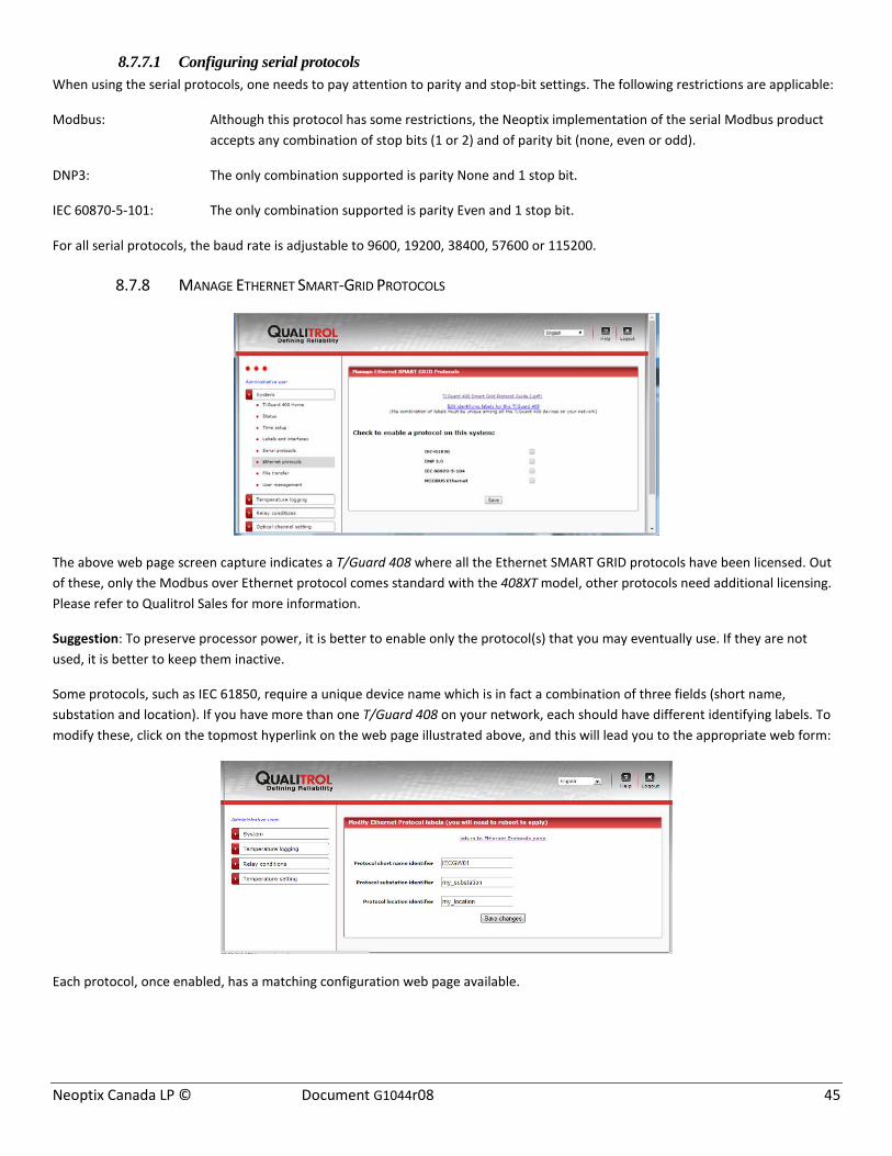
Neoptix Canada LP © Document G1044r08 45
8.7.7.1 Configuring serial protocols When using the serial protocols, one needs to pay attention to parity and stop-bit settings. The following restrictions are applicable:
Modbus: Although this protocol has some restrictions, the Neoptix implementation of the serial Modbus product accepts any combination of stop bits (1 or 2) and of parity bit (none, even or odd).
DNP3: The only combination supported is parity None and 1 stop bit.
IEC 60870-5-101: The only combination supported is parity Even and 1 stop bit.
For all serial protocols, the baud rate is adjustable to 9600, 19200, 38400, 57600 or 115200.
8.7.8 MANAGE ETHERNET SMART-GRID PROTOCOLS
The above web page screen capture indicates a T/Guard 408 where all the Ethernet SMART GRID protocols have been licensed. Out of these, only the Modbus over Ethernet protocol comes standard with the 408XT model, other protocols need additional licensing. Please refer to Qualitrol Sales for more information.
Suggestion: To preserve processor power, it is better to enable only the protocol(s) that you may eventually use. If they are not used, it is better to keep them inactive.
Some protocols, such as IEC 61850, require a unique device name which is in fact a combination of three fields (short name, substation and location). If you have more than one T/Guard 408 on your network, each should have different identifying labels. To modify these, click on the topmost hyperlink on the web page illustrated above, and this will lead you to the appropriate web form:
Each protocol, once enabled, has a matching configuration web page available.

Neoptix Canada LP © Document G1044r08 46
More than one protocol can be enabled at the same time, as illustrated above, however, if you are not using a given protocol then you should not enable it as it will engage system resources unnecessarily and impact overall performance.
8.7.9 CONFIGURATION WEB PAGE FOR THE IEC 61850 PROTOCOL
The IEC 61850 protocol by default does not require a password, and allows any client to connect to it. It is possible to enforce the exchange of passwords by checking the Security Mode checkbox in the web page illustrated above.
This will allow the setting of three different passwords:
Saving passwords here will force a client to provide one of the three passwords in order to connect. There is currently no difference in functionality offered by the protocol depending on the level of security, i.e. each password will have access to exactly the same information.
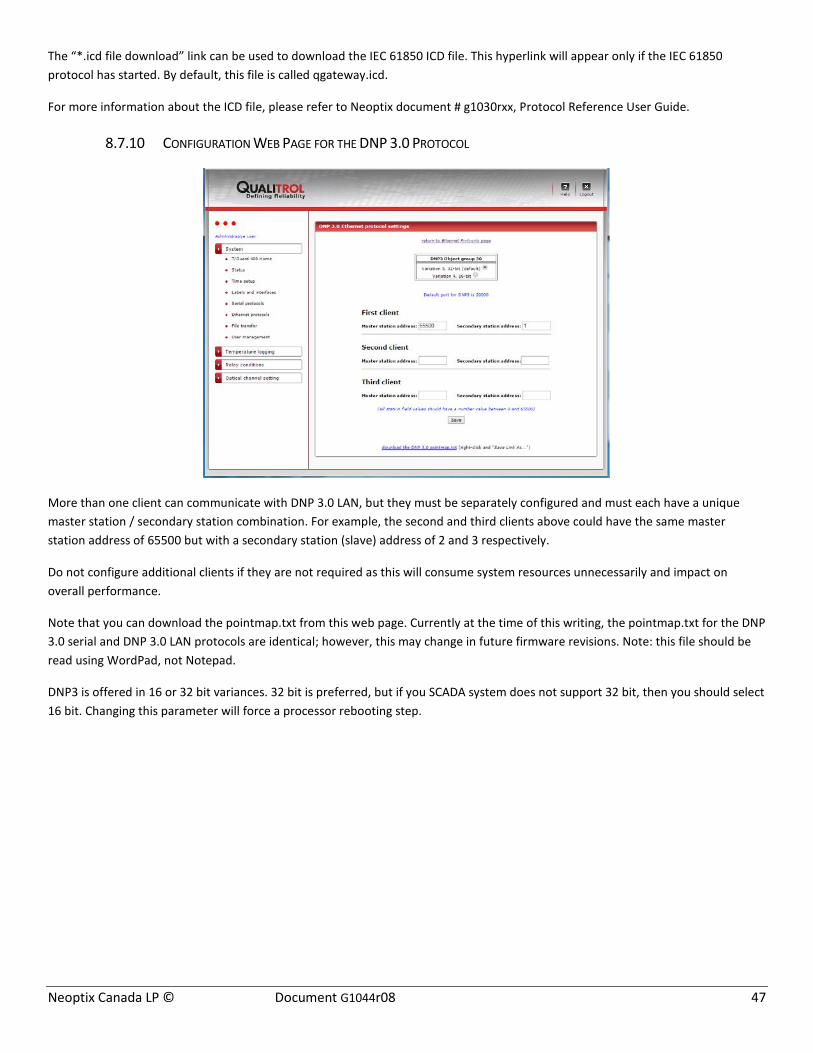
Neoptix Canada LP © Document G1044r08 47
The “*.icd file download” link can be used to download the IEC 61850 ICD file. This hyperlink will appear only if the IEC 61850 protocol has started. By default, this file is called qgateway.icd.
For more information about the ICD file, please refer to Neoptix document # g1030rxx, Protocol Reference User Guide.
8.7.10 CONFIGURATION WEB PAGE FOR THE DNP 3.0 PROTOCOL
More than one client can communicate with DNP 3.0 LAN, but they must be separately configured and must each have a unique master station / secondary station combination. For example, the second and third clients above could have the same master station address of 65500 but with a secondary station (slave) address of 2 and 3 respectively.
Do not configure additional clients if they are not required as this will consume system resources unnecessarily and impact on overall performance.
Note that you can download the pointmap.txt from this web page. Currently at the time of this writing, the pointmap.txt for the DNP 3.0 serial and DNP 3.0 LAN protocols are identical; however, this may change in future firmware revisions. Note: this file should be read using WordPad, not Notepad.
DNP3 is offered in 16 or 32 bit variances. 32 bit is preferred, but if you SCADA system does not support 32 bit, then you should select 16 bit. Changing this parameter will force a processor rebooting step.
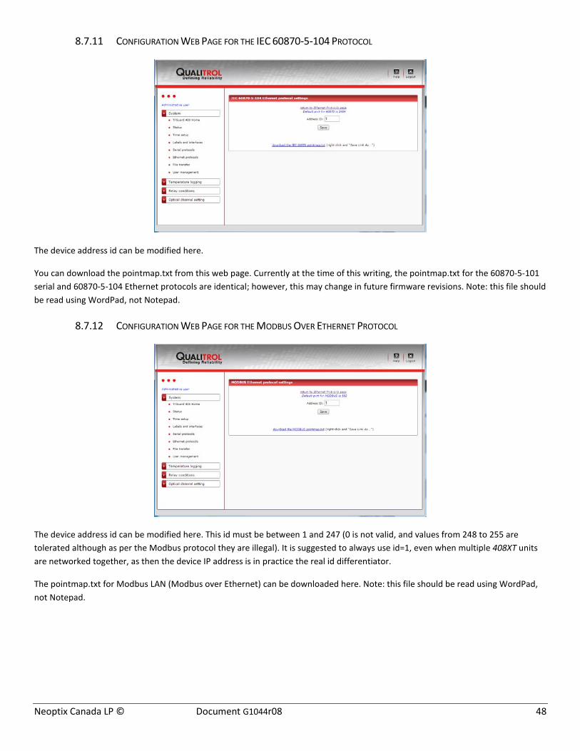
Neoptix Canada LP © Document G1044r08 48
8.7.11 CONFIGURATION WEB PAGE FOR THE IEC 60870-5-104 PROTOCOL
The device address id can be modified here.
You can download the pointmap.txt from this web page. Currently at the time of this writing, the pointmap.txt for the 60870-5-101 serial and 60870-5-104 Ethernet protocols are identical; however, this may change in future firmware revisions. Note: this file should be read using WordPad, not Notepad.
8.7.12 CONFIGURATION WEB PAGE FOR THE MODBUS OVER ETHERNET PROTOCOL
The device address id can be modified here. This id must be between 1 and 247 (0 is not valid, and values from 248 to 255 are tolerated although as per the Modbus protocol they are illegal). It is suggested to always use id=1, even when multiple 408XT units are networked together, as then the device IP address is in practice the real id differentiator.
The pointmap.txt for Modbus LAN (Modbus over Ethernet) can be downloaded here. Note: this file should be read using WordPad, not Notepad.

Neoptix Canada LP © Document G1044r08 49
8.7.13 FILE TRANSFER
On this web page, it is possible to download (transferring a file to your PC):
• The locally stored PDF user guides (408 and smart protocols) • The user, relay condition and relay name custom configurations (.cfg files)
o These files are useful to reconfigure a similar instrument exactly as this one. Do not edit these files! • The status file (includes most general parameters); this file is very useful to view an overall picture of a 408, in text
form. This is a very useful file to email to Neoptix, to help diagnose problems • The TransLife log file. This is also a .cfg file; it can be downloaded from this instrument and then uploaded to a new
instrument. It is not strictly speaking a configuration but rather a log file that includes the accumulated Translife life use from this instrument; so, uploading this file to a new instrument will allow this new instrument to continue evaluating the loss of life for a given transformer.
This figure shows the complete list of files that can be downloaded:
It is also possible to upload (transferring a file to the 408XT):
• Web server file updates (other than .php extension files, which can only be updated via a firmware update); this type of upload must only be done under the supervision of a Neoptix support engineer
• A visual jpeg file can also be uploaded to replace the standard image supplied with your instrument. This is the image that appears in the web page described in section 8.7.30
• The user, relay condition and relay name custom configurations (.cfg) to duplicate settings from another unit (previously downloaded).

Neoptix Canada LP © Document G1044r08 50
Web server files should be uploaded only under the supervision of a Neoptix support engineer. This type of upload can be to perform minor firmware upgrades. Generally speaking, a full upgrade (see below) would be preferable to a partial upgrade.
The upgrade file would normally be sent to you by a Neoptix engineer; the file is normally sent in zip format; you will need to unzip it to a local drive before proceeding with the upgrade.
It is also possible to reset the unit to factory defaults, or to restart the unit. This can be done using the “Reset” button found on the same web page.
8.7.14 USER MANAGEMENT PAGE
This web page lists current users and provides an “Add New User” button. A maximum of 10 different users can be configured on the system.
To modify the role for, and/or delete or rename a user login/password, click on the hyperlink. Please note that the factory-provided default user cannot be deleted, nor can the user role for this account be changed.
8.7.15 ADD NEW USER PAGE
This page will be available only as long as there are ten or less user accounts, as only a maximum of 10 is supported. A given user name can be used only once.
This window is self-explaining.

Neoptix Canada LP © Document G1044r08 51
8.7.16 MODIFY MAIN USER ROLE PAGE
Both the password and the login name can be changed.
Once again, please remember that the “admin user” is the only account which cannot be deleted, although the original factory login and password can be restored, by following this procedure: There is a reset button sequence available on the local keypad of the 408XT to restore the default web user: simply hold down the left two buttons (MENU and OK) simultaneously for 5 seconds and the message “web user reset” will appear for a few seconds. You will then be able to log in using the original user name (neoptix) and password (pass) provided by default with the device.
8.7.17 MODIFY / DELETE OTHER USER PAGE
A user other than the main regular one can be deleted, and his login, password or role can be changed.

Neoptix Canada LP © Document G1044r08 52
8.7.18 LOG DOWNLOAD (AND DELETE) PAGE
Available temperature logs can be downloaded by clicking the hyperlink link.
Temperature logs are in fact tab-separated .csv text files renamed to a .tem file extension. The .tem file extension name is a convenience allowing users to associate this file type to Microsoft Excel on their workstation. This convenience has been extended in the T/Guard 408XT to associate in the web server the .tem file extension with Microsoft Excel. By clicking the link on this web page, you will be able to either save the file to local disk, or to open the downloaded log directly in Microsoft Excel.
Here is an example screenshot of the Firefox web browser message:
If you use another program than Microsoft Excel, it is recommended you save the file to disk first. If you get the following message:
Click “yes” to continue. Excel should then come up with a file that would look like this:
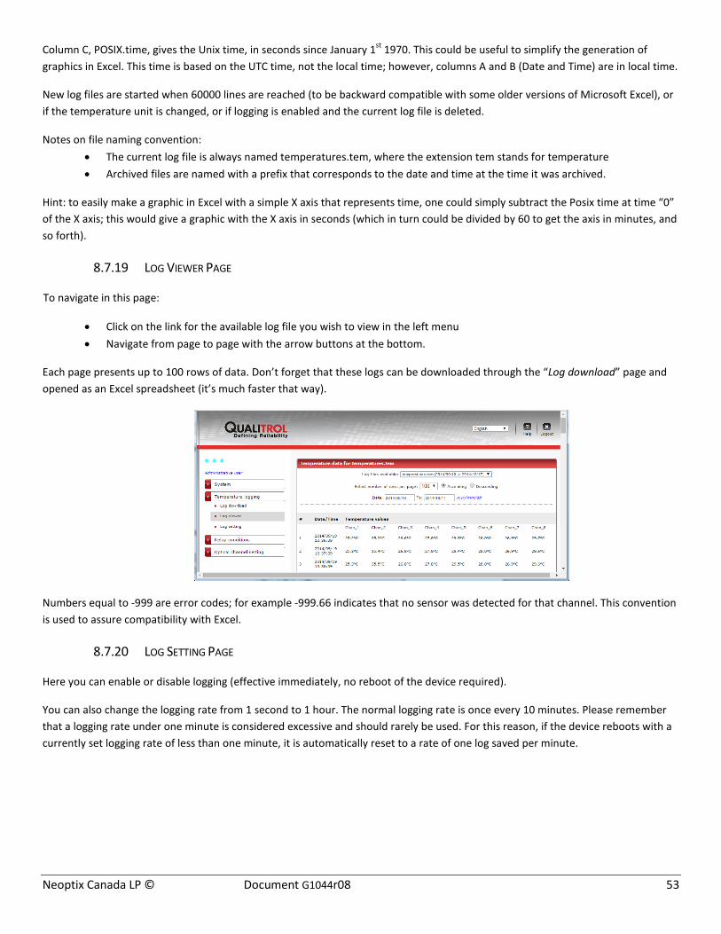
Neoptix Canada LP © Document G1044r08 53
Column C, POSIX.time, gives the Unix time, in seconds since January 1st 1970. This could be useful to simplify the generation of graphics in Excel. This time is based on the UTC time, not the local time; however, columns A and B (Date and Time) are in local time.
New log files are started when 60000 lines are reached (to be backward compatible with some older versions of Microsoft Excel), or if the temperature unit is changed, or if logging is enabled and the current log file is deleted.
Notes on file naming convention: • The current log file is always named temperatures.tem, where the extension tem stands for temperature • Archived files are named with a prefix that corresponds to the date and time at the time it was archived.
Hint: to easily make a graphic in Excel with a simple X axis that represents time, one could simply subtract the Posix time at time “0” of the X axis; this would give a graphic with the X axis in seconds (which in turn could be divided by 60 to get the axis in minutes, and so forth).
8.7.19 LOG VIEWER PAGE
To navigate in this page:
• Click on the link for the available log file you wish to view in the left menu • Navigate from page to page with the arrow buttons at the bottom.
Each page presents up to 100 rows of data. Don’t forget that these logs can be downloaded through the “Log download” page and opened as an Excel spreadsheet (it’s much faster that way).
Numbers equal to -999 are error codes; for example -999.66 indicates that no sensor was detected for that channel. This convention is used to assure compatibility with Excel.
8.7.20 LOG SETTING PAGE
Here you can enable or disable logging (effective immediately, no reboot of the device required).
You can also change the logging rate from 1 second to 1 hour. The normal logging rate is once every 10 minutes. Please remember that a logging rate under one minute is considered excessive and should rarely be used. For this reason, if the device reboots with a currently set logging rate of less than one minute, it is automatically reset to a rate of one log saved per minute.

Neoptix Canada LP © Document G1044r08 54
A modified logging rate is also applied immediately.
8.7.21 RELAY CONDITION OVERVIEW PAGE
This page lists a summary of all 128 relay conditions in one convenient web page. Refer to the next sections for instructions on how to set these conditions. This page is read only. One can get the same information by downloading the status page; see Section 8.7.13.
8.7.22 RELAY SETUP PAGE
As a first step, it might be a good idea to “name” the relays according to their logical function; this can be done selecting in the navigation links on the left, “Relay conditions” > “Relay setting”, as shown here:
This window gives you also the opportunity to define any relay as being in “Fail Safe” mode, which will inverse the physical logic assigned to this relay. Please note that after a power up sequence, it will take about 20 to 30 seconds before the fail safe mode is enforced; for this reason, all relays that are set in fail safe mode, should be implemented using a “time delay relay” (delay on operate), to avoid problems at system power up.
Then you should select “Relay conditions” > “Condition setting”; experimenting with this window, shown below, would be a good way to learn about relay condition setting.
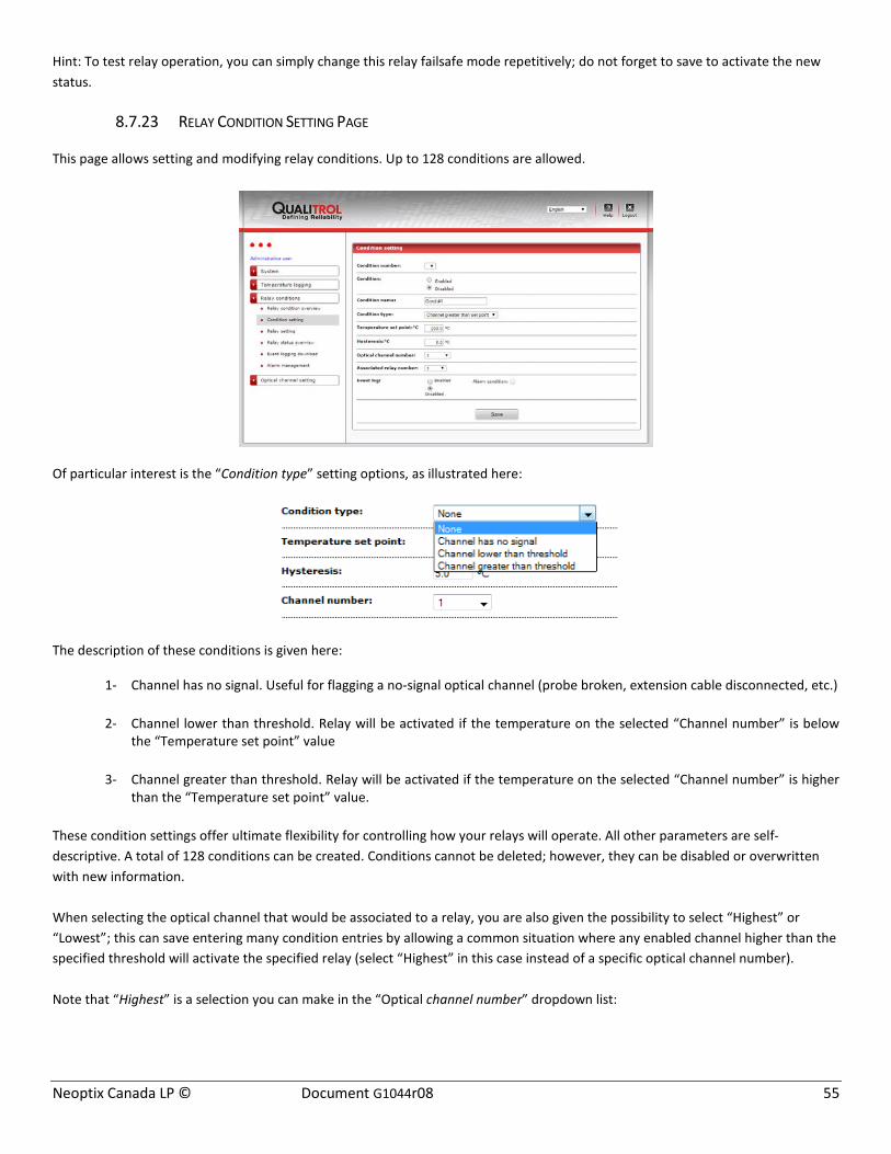
Neoptix Canada LP © Document G1044r08 55
Hint: To test relay operation, you can simply change this relay failsafe mode repetitively; do not forget to save to activate the new status.
8.7.23 RELAY CONDITION SETTING PAGE
This page allows setting and modifying relay conditions. Up to 128 conditions are allowed.
Of particular interest is the “Condition type” setting options, as illustrated here:
The description of these conditions is given here:
1- Channel has no signal. Useful for flagging a no-signal optical channel (probe broken, extension cable disconnected, etc.)
2- Channel lower than threshold. Relay will be activated if the temperature on the selected “Channel number” is below the “Temperature set point” value
3- Channel greater than threshold. Relay will be activated if the temperature on the selected “Channel number” is higher than the “Temperature set point” value.
These condition settings offer ultimate flexibility for controlling how your relays will operate. All other parameters are self-descriptive. A total of 128 conditions can be created. Conditions cannot be deleted; however, they can be disabled or overwritten with new information. When selecting the optical channel that would be associated to a relay, you are also given the possibility to select “Highest” or “Lowest”; this can save entering many condition entries by allowing a common situation where any enabled channel higher than the specified threshold will activate the specified relay (select “Highest” in this case instead of a specific optical channel number). Note that “Highest” is a selection you can make in the “Optical channel number” dropdown list:

Neoptix Canada LP © Document G1044r08 56
When a relay condition is triggered, this constitutes an “event”. An event can be either logged or not for a given condition. Also, an event can also be defined as an alarm.
Some comments on “Event logging” options: Events are defined as an operational condition that might be useful to log. Not all relay operations should be labeled as events; indeed, for example if a relay is controlling a fan cooling bank, this is probably not an event, so its logging would probably be disabled, and it should not create an alarm situation. On another hand, if you have a condition whereby the temperature on any probes is higher than 120oC, and it is required to trip the transformer, this is clearly an event that should be logged and create an alarm situation when it occurs. Remember that any alarm must be acknowledged on the T/Guard-408 local keypad; one would normally not want thousands of those!
Each event that has created a logged alarm condition will have 2 entries in the event log file: the first entry will occur when the alarm condition is created and the second entry will be when this condition ceases to exist.
Any non-acknowledged alarms are automatically acknowledged when the system reboots. However, all alarms already logged in the event log file are kept permanently, unless this file is intentionally deleted.
Alarms are special in several ways:
• They are always logged; • The last 10 alarms are displayed on the “T/Guard 408 Home” start web page and on the “Manage Alarms” web page, in
order of the most recent to oldest; • On the “T/Guard 408 Home” start web page, the “Alarms” section is refreshed every 10 seconds; • Alarms can be dismissed on the “Manage Alarms” web page by clicking the “Acknowledge to clear alarms” button.
On the T/Guard 408 front panel display, the LED marked \“Alarm OK to Clear\” will light up if there is at least one alarm (please note that only T/Guard 408 units marked with this indication will provide this last functionality);
• Alarms can be dismissed from the display by simply clicking the OK button while temperatures are being displayed (please note that only T/Guard 408 units marked with this indication will provide this last functionality).
Although it is possible to copy relay condition name settings from one T/Guard 408 device to another using the File Transfer web page, please note that relay condition names are a web-only convenience and exist only on the 408XT model. For this reason, they are stored differently and require a separate file download and upload, i.e. the item “T/Guard 408 Relay Condition Name List (.cfg)”.
8.7.24 RELAY CONDITION EXAMPLE
This example assumes that 4 probes are installed in the transformer. In this example, a probe is used to control the fan cooling (this would normally be the probe that would have exhibited the highest temperature readings during the heat run test).
Probe locations (4):
1- Winding, high voltage (W-HV); connected to channel # 1 on T/Guard 408 2- Winding, low voltage (W-LV); connected to channel # 2 on T/Guard 408 3- Winding, tertiary (W-TV); connected to channel # 3 on T/Guard 408 4- Winding, low voltage (W-LV) (could be a spare to probe # 2); connected to channel # 4 on T/Guard 408.
Relay definitions (6):

Neoptix Canada LP © Document G1044r08 57
1- Relay # 1, for cooling fans, bank # 1. Should be activated when probe # 1 reaches +70oC 2- Relay # 2, for cooling fans, bank # 2. Should be activated when probe # 1 reaches +80oC 3- Relay # 3, alarm, level # 1. Should be activated when probe # 2 reaches +95oC 4- Relay # 4, alarm, level # 2. Should be activated when probe # 2 reaches +105oC 5- Relay # 5, alarm, level # 3. Should be activated when probe # 3 reaches +110oC 6- Relay # 6, transformer trip. Should be activated when any of the 4 probes reach(es) +120oC.
Assuming the above conditions, the following parameters would need to be set, either via the web browser or by relay condition files (with OptiLink-II).
Cond.
#
Cond.
Name
Cond.
Type
Set
Point
Hyst. Ch #
Assoc.
Relay#
1 Bank1 Channel greater than threshold
70 5 1 1
2 Bank2 Channel greater than threshold
80 5 1 2
3 Alarm1 Channel greater than threshold
95 5 2 3
4 Alarm2 Channel greater than threshold
105 5 2 4
5 Alarm3 Channel greater than threshold
110 5 3 5
6 Tfr-Trip Channel greater than threshold
120 5 Highest 6
8.7.25 EVENT LOGGING DOWNLOAD PAGE
On this web page, an event log can be downloaded by clicking on the hyperlink.
Just like a temperature log, an event log is limited to 65,000 lines. If it exceeds that, it is archived. Archives will also be displayed here and can be downloaded. Event files are tab delimited .csv files, and can be directly read by Excel.
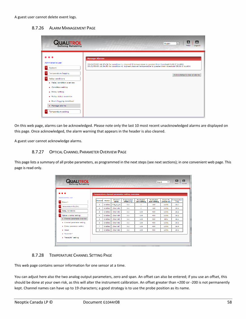
Neoptix Canada LP © Document G1044r08 58
A guest user cannot delete event logs.
8.7.26 ALARM MANAGEMENT PAGE
On this web page, alarms can be acknowledged. Please note only the last 10 most recent unacknowledged alarms are displayed on this page. Once acknowledged, the alarm warning that appears in the header is also cleared.
A guest user cannot acknowledge alarms.
8.7.27 OPTICAL CHANNEL PARAMETER OVERVIEW PAGE
This page lists a summary of all probe parameters, as programmed in the next steps (see next sections); in one convenient web page. This page is read only.
8.7.28 TEMPERATURE CHANNEL SETTING PAGE
This web page contains sensor information for one sensor at a time. You can adjust here also the two analog output parameters, zero and span. An offset can also be entered; if you use an offset, this should be done at your own risk, as this will alter the instrument calibration. An offset greater than +200 or -200 is not permanently kept. Channel names can have up to 19 characters; a good strategy is to use the probe position as its name.
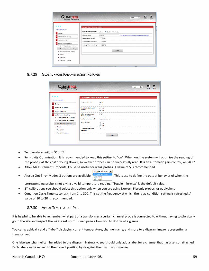
Neoptix Canada LP © Document G1044r08 59
8.7.29 GLOBAL PROBE PARAMETER SETTING PAGE
• Temperature unit, in oC or oF. • Sensitivity Optimization: It is recommended to keep this setting to “on”. When on, the system will optimize the reading of
the probes, at the cost of being slower, so weaker probes can be successfully read. It is an automatic gain control, or “AGC”. • Allow Measurement Dropouts: Could be useful for weak probes. A value of 5 is recommended.
• Analog Out Error Mode: 3 options are available: . This is use to define the output behavior of when the
corresponding probe is not giving a valid temperature reading. “Toggle min-max” is the default value. • 2nd calibration: You should select this option only when you are using Nortech Fibronic probes, or equivalent. • Condition Cycle Time (seconds), from 1 to 300: This set the frequency at which the relay condition setting is refreshed. A
value of 10 to 20 is recommended.
8.7.30 VISUAL TEMPERATURE PAGE
It is helpful to be able to remember what part of a transformer a certain channel probe is connected to without having to physically go to the site and inspect the wiring set up. This web page allows you to do this at a glance.
You can graphically add a “label” displaying current temperature, channel name, and more to a diagram image representing a transformer.
One label per channel can be added to the diagram. Naturally, you should only add a label for a channel that has a sensor attached. Each label can be moved to the correct position by dragging them with your mouse.
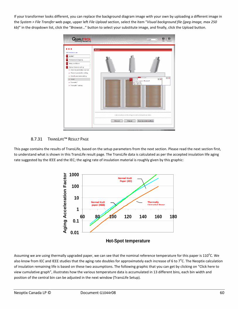
Neoptix Canada LP © Document G1044r08 60
If your transformer looks different, you can replace the background diagram image with your own by uploading a different image in the System > File Transfer web page, upper left File Upload section, select the item “Visual background file (jpeg image, max 250 kb)” in the dropdown list, click the “Browse…” button to select your substitute image, and finally, click the Upload button.
8.7.31 TRANSLIFE™ RESULT PAGE
This page contains the results of TransLife, based on the setup parameters from the next section. Please read the next section first, to understand what is shown in this TransLife result page. The TransLife data is calculated as per the accepted insulation life aging rate suggested by the IEEE and the IEC; the aging rate of insulation material is roughly given by this graphic:
Assuming we are using thermally upgraded paper, we can see that the nominal reference temperature for this paper is 110oC. We also know from IEC and IEEE studies that the aging rate doubles for approximately each increase of 6 to 7oC. The Neoptix calculation of insulation remaining life is based on these two assumptions. The following graphic that you can get by clicking on “Click here to view cumulative graph”, illustrates how the various temperature data is accumulated in 13 different bins, each bin width and position of the central bin can be adjusted in the next window (TransLife Setup).
0.01
0.1
1
10
100
1000
60 80 100 120 140 160 180
Hot-Spot temperature
Agi
ng A
ccel
erat
ion
Fact
or Normal Kraft Paper (IEC)
Normal Kraft paper (IEEE)
.
Thermally Upgraded Paper

Neoptix Canada LP © Document G1044r08 61
Currently, TransLife is only available on the 408XT instrument (it is not available on the 408).
8.7.32 TRANSLIFE™ SETUP PAGE
This page contains the parameters that are used to setup TransLife (previous section).
This is the central bin, centered on 110 oC, in this example. Bin width is 6.5 oC.
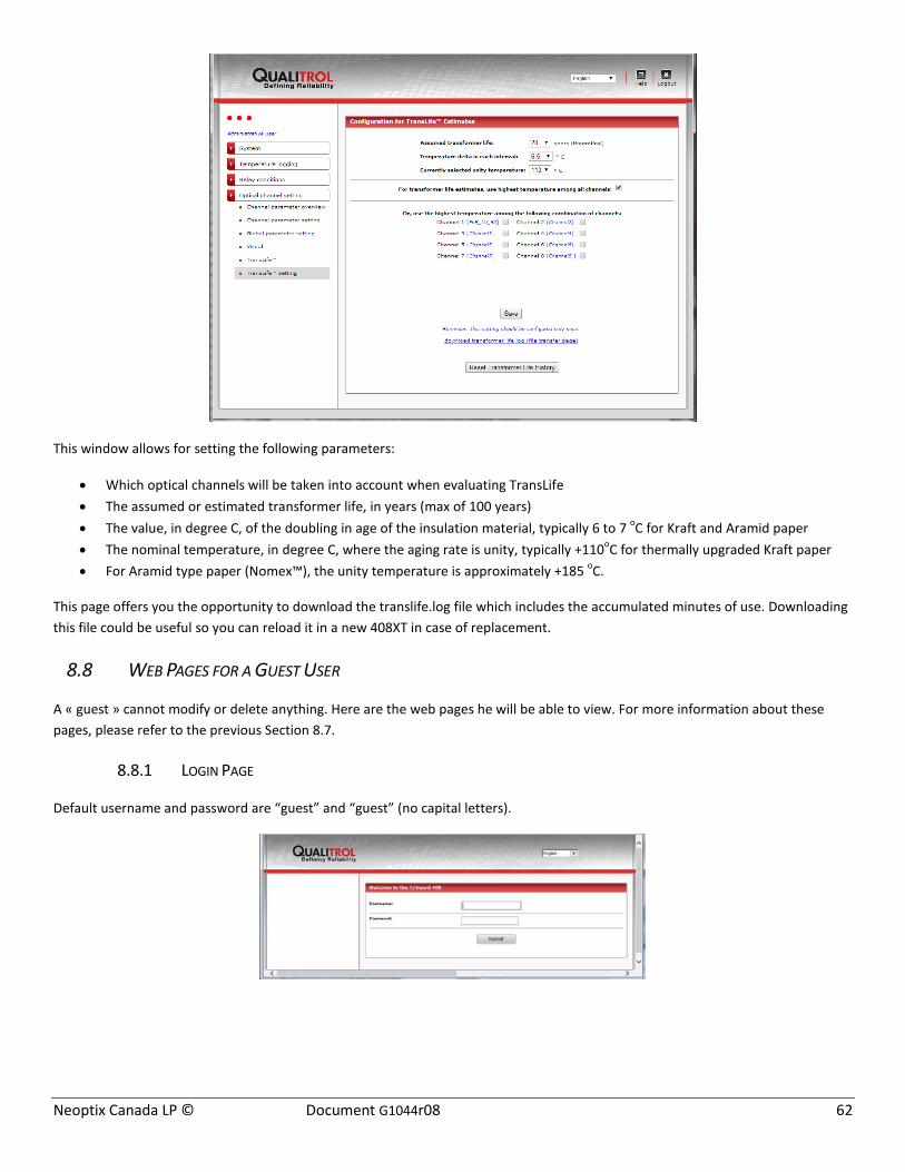
Neoptix Canada LP © Document G1044r08 62
This window allows for setting the following parameters:
• Which optical channels will be taken into account when evaluating TransLife • The assumed or estimated transformer life, in years (max of 100 years) • The value, in degree C, of the doubling in age of the insulation material, typically 6 to 7 oC for Kraft and Aramid paper • The nominal temperature, in degree C, where the aging rate is unity, typically +110oC for thermally upgraded Kraft paper • For Aramid type paper (Nomex™), the unity temperature is approximately +185 oC.
This page offers you the opportunity to download the translife.log file which includes the accumulated minutes of use. Downloading this file could be useful so you can reload it in a new 408XT in case of replacement.
8.8 WEB PAGES FOR A GUEST USER
A « guest » cannot modify or delete anything. Here are the web pages he will be able to view. For more information about these pages, please refer to the previous Section 8.7.
8.8.1 LOGIN PAGE
Default username and password are “guest” and “guest” (no capital letters).
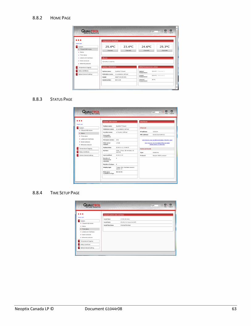
Neoptix Canada LP © Document G1044r08 63
8.8.2 HOME PAGE
8.8.3 STATUS PAGE
8.8.4 TIME SETUP PAGE

Neoptix Canada LP © Document G1044r08 64
8.8.5 LABELS AND INTERFACES PAGE
8.8.6 SERIAL PROTOCOLS
8.8.7 ETHERNET PROTOCOLS
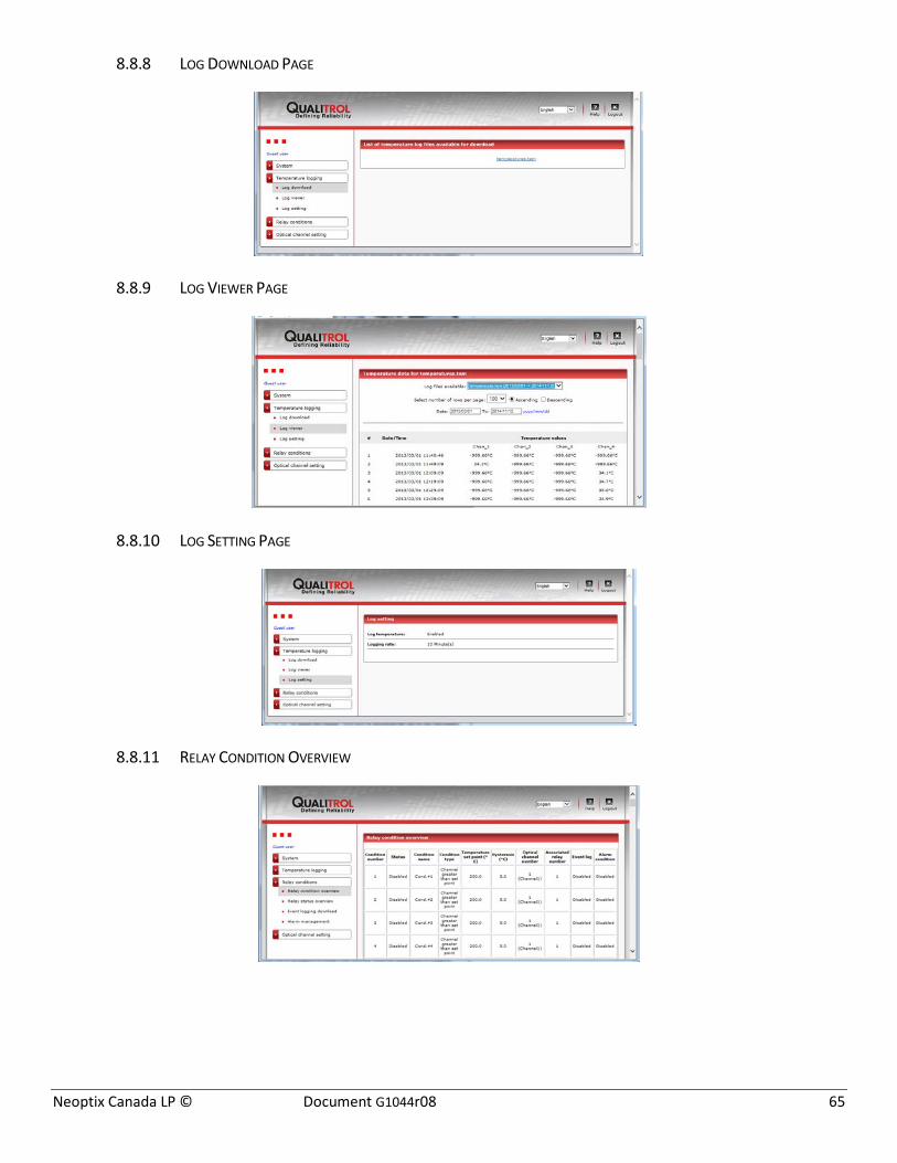
Neoptix Canada LP © Document G1044r08 65
8.8.8 LOG DOWNLOAD PAGE
8.8.9 LOG VIEWER PAGE
8.8.10 LOG SETTING PAGE
8.8.11 RELAY CONDITION OVERVIEW
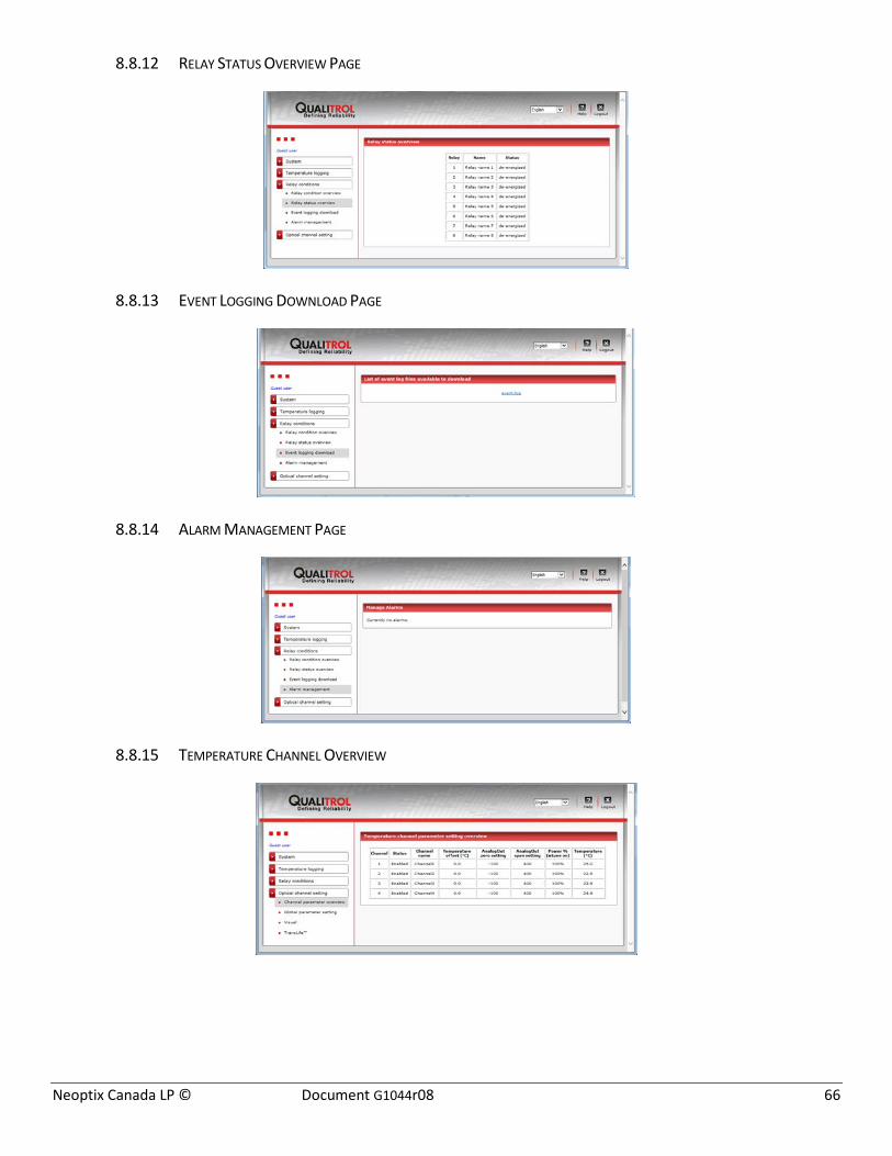
Neoptix Canada LP © Document G1044r08 66
8.8.12 RELAY STATUS OVERVIEW PAGE
8.8.13 EVENT LOGGING DOWNLOAD PAGE
8.8.14 ALARM MANAGEMENT PAGE
8.8.15 TEMPERATURE CHANNEL OVERVIEW

Neoptix Canada LP © Document G1044r08 67
8.8.16 GLOBAL PARAMETER PAGE
8.8.17 VISUAL TEMPERATURE PAGE
8.8.18 TRANSLIFE™ RESULTS
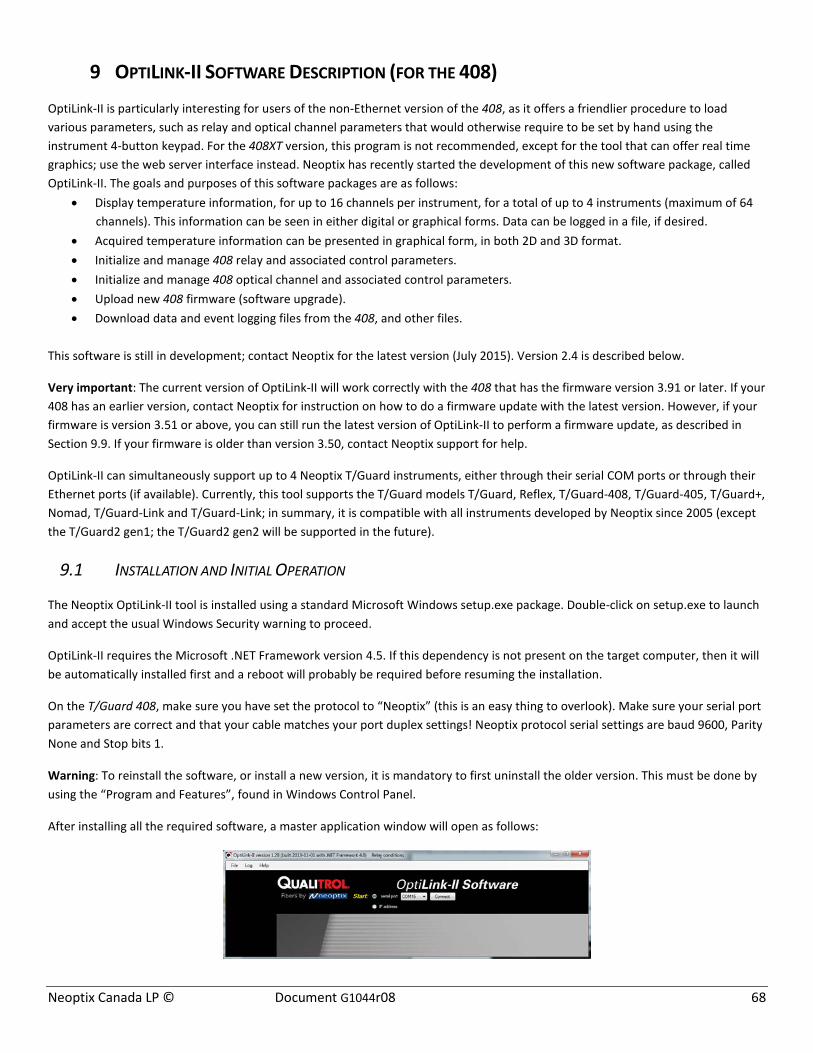
Neoptix Canada LP © Document G1044r08 68
9 OPTILINK-II SOFTWARE DESCRIPTION (FOR THE 408)
OptiLink-II is particularly interesting for users of the non-Ethernet version of the 408, as it offers a friendlier procedure to load various parameters, such as relay and optical channel parameters that would otherwise require to be set by hand using the instrument 4-button keypad. For the 408XT version, this program is not recommended, except for the tool that can offer real time graphics; use the web server interface instead. Neoptix has recently started the development of this new software package, called OptiLink-II. The goals and purposes of this software packages are as follows:
• Display temperature information, for up to 16 channels per instrument, for a total of up to 4 instruments (maximum of 64 channels). This information can be seen in either digital or graphical forms. Data can be logged in a file, if desired.
• Acquired temperature information can be presented in graphical form, in both 2D and 3D format. • Initialize and manage 408 relay and associated control parameters. • Initialize and manage 408 optical channel and associated control parameters. • Upload new 408 firmware (software upgrade). • Download data and event logging files from the 408, and other files.
This software is still in development; contact Neoptix for the latest version (July 2015). Version 2.4 is described below.
Very important: The current version of OptiLink-II will work correctly with the 408 that has the firmware version 3.91 or later. If your 408 has an earlier version, contact Neoptix for instruction on how to do a firmware update with the latest version. However, if your firmware is version 3.51 or above, you can still run the latest version of OptiLink-II to perform a firmware update, as described in Section 9.9. If your firmware is older than version 3.50, contact Neoptix support for help.
OptiLink-II can simultaneously support up to 4 Neoptix T/Guard instruments, either through their serial COM ports or through their Ethernet ports (if available). Currently, this tool supports the T/Guard models T/Guard, Reflex, T/Guard-408, T/Guard-405, T/Guard+, Nomad, T/Guard-Link and T/Guard-Link; in summary, it is compatible with all instruments developed by Neoptix since 2005 (except the T/Guard2 gen1; the T/Guard2 gen2 will be supported in the future).
9.1 INSTALLATION AND INITIAL OPERATION
The Neoptix OptiLink-II tool is installed using a standard Microsoft Windows setup.exe package. Double-click on setup.exe to launch and accept the usual Windows Security warning to proceed.
OptiLink-II requires the Microsoft .NET Framework version 4.5. If this dependency is not present on the target computer, then it will be automatically installed first and a reboot will probably be required before resuming the installation.
On the T/Guard 408, make sure you have set the protocol to “Neoptix” (this is an easy thing to overlook). Make sure your serial port parameters are correct and that your cable matches your port duplex settings! Neoptix protocol serial settings are baud 9600, Parity None and Stop bits 1.
Warning: To reinstall the software, or install a new version, it is mandatory to first uninstall the older version. This must be done by using the “Program and Features”, found in Windows Control Panel.
After installing all the required software, a master application window will open as follows:

Neoptix Canada LP © Document G1044r08 69
Or
All applications will require that you know which serial com port or which IP address is used to connect a Neoptix instrument11 to OptiLink-II. For this purpose, each application has a port selector and a Connect button. The COM port selector will only list the currently available ports on your Windows installation (for Ethernet connection, you must enter the full IP address). This is the same list of available COM ports you would view in your Windows Hardware Device Manager:
Select the port connected to your T/Guard 408 and click the “Connect” button.
Information confirms you have indeed communicated with the T/Guard and you will be provided with additional menu items (left pane). If connected through an IP address, only the Acquire Temperatures item is available.
9.2 ACQUIRE AND DISPLAY TEMPERATURE DATA
The “Acquire Temperatures” application will display up to 64 temperatures (16 temperatures for up to 4 instruments), as follows:
11 The Acquire Temperature window allows connecting up to 4 compatible instruments to OptiLink-II simultaneously; all Neoptix instruments are compatible with OptiLink-II.
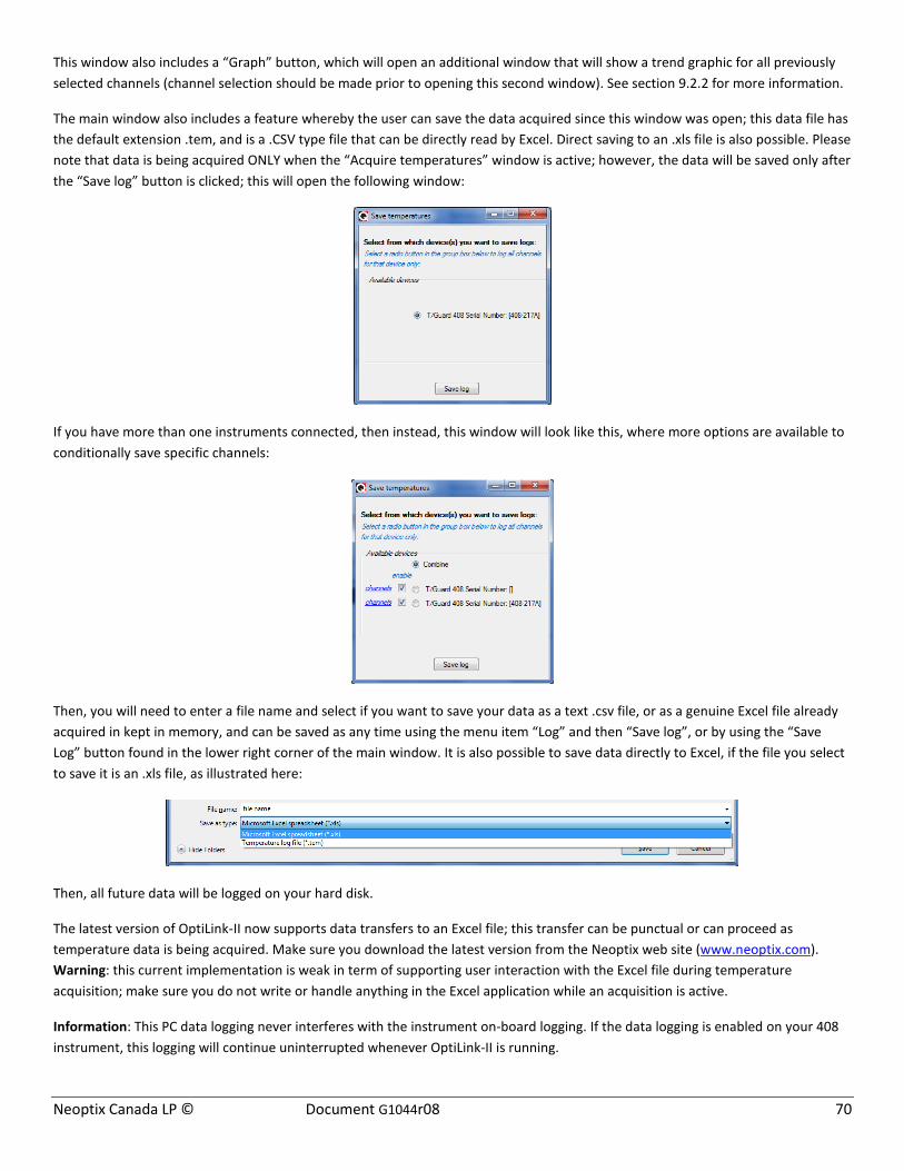
Neoptix Canada LP © Document G1044r08 70
This window also includes a “Graph” button, which will open an additional window that will show a trend graphic for all previously selected channels (channel selection should be made prior to opening this second window). See section 9.2.2 for more information.
The main window also includes a feature whereby the user can save the data acquired since this window was open; this data file has the default extension .tem, and is a .CSV type file that can be directly read by Excel. Direct saving to an .xls file is also possible. Please note that data is being acquired ONLY when the “Acquire temperatures” window is active; however, the data will be saved only after the “Save log” button is clicked; this will open the following window:
If you have more than one instruments connected, then instead, this window will look like this, where more options are available to conditionally save specific channels:
Then, you will need to enter a file name and select if you want to save your data as a text .csv file, or as a genuine Excel file already acquired in kept in memory, and can be saved as any time using the menu item “Log” and then “Save log”, or by using the “Save Log” button found in the lower right corner of the main window. It is also possible to save data directly to Excel, if the file you select to save it is an .xls file, as illustrated here:
Then, all future data will be logged on your hard disk.
The latest version of OptiLink-II now supports data transfers to an Excel file; this transfer can be punctual or can proceed as temperature data is being acquired. Make sure you download the latest version from the Neoptix web site (www.neoptix.com). Warning: this current implementation is weak in term of supporting user interaction with the Excel file during temperature acquisition; make sure you do not write or handle anything in the Excel application while an acquisition is active.
Information: This PC data logging never interferes with the instrument on-board logging. If the data logging is enabled on your 408 instrument, this logging will continue uninterrupted whenever OptiLink-II is running.
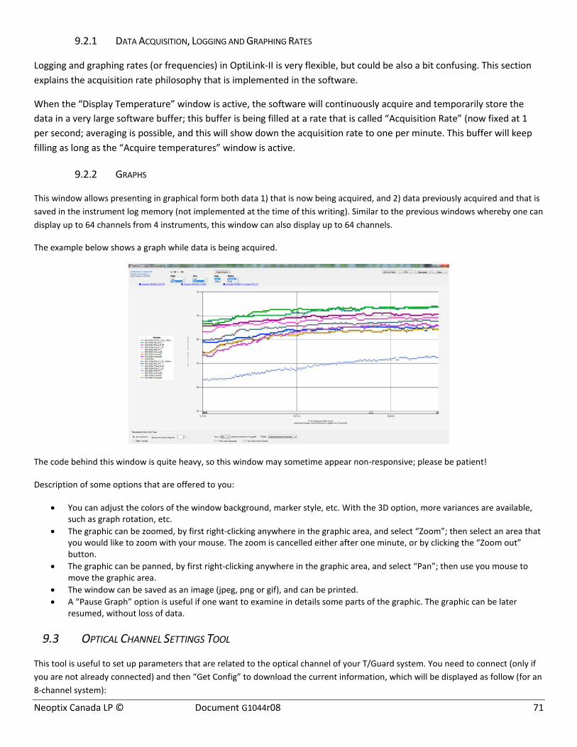
Neoptix Canada LP © Document G1044r08 71
9.2.1 DATA ACQUISITION, LOGGING AND GRAPHING RATES
Logging and graphing rates (or frequencies) in OptiLink-II is very flexible, but could be also a bit confusing. This section explains the acquisition rate philosophy that is implemented in the software.
When the “Display Temperature” window is active, the software will continuously acquire and temporarily store the data in a very large software buffer; this buffer is being filled at a rate that is called “Acquisition Rate” (now fixed at 1 per second; averaging is possible, and this will show down the acquisition rate to one per minute. This buffer will keep filling as long as the “Acquire temperatures” window is active.
9.2.2 GRAPHS
This window allows presenting in graphical form both data 1) that is now being acquired, and 2) data previously acquired and that is saved in the instrument log memory (not implemented at the time of this writing). Similar to the previous windows whereby one can display up to 64 channels from 4 instruments, this window can also display up to 64 channels.
The example below shows a graph while data is being acquired.
The code behind this window is quite heavy, so this window may sometime appear non-responsive; please be patient!
Description of some options that are offered to you:
• You can adjust the colors of the window background, marker style, etc. With the 3D option, more variances are available, such as graph rotation, etc.
• The graphic can be zoomed, by first right-clicking anywhere in the graphic area, and select “Zoom”; then select an area that you would like to zoom with your mouse. The zoom is cancelled either after one minute, or by clicking the “Zoom out” button.
• The graphic can be panned, by first right-clicking anywhere in the graphic area, and select “Pan”; then use you mouse to move the graphic area.
• The window can be saved as an image (jpeg, png or gif), and can be printed. • A “Pause Graph” option is useful if one want to examine in details some parts of the graphic. The graphic can be later
resumed, without loss of data.
9.3 OPTICAL CHANNEL SETTINGS TOOL
This tool is useful to set up parameters that are related to the optical channel of your T/Guard system. You need to connect (only if you are not already connected) and then “Get Config” to download the current information, which will be displayed as follow (for an 8-channel system):
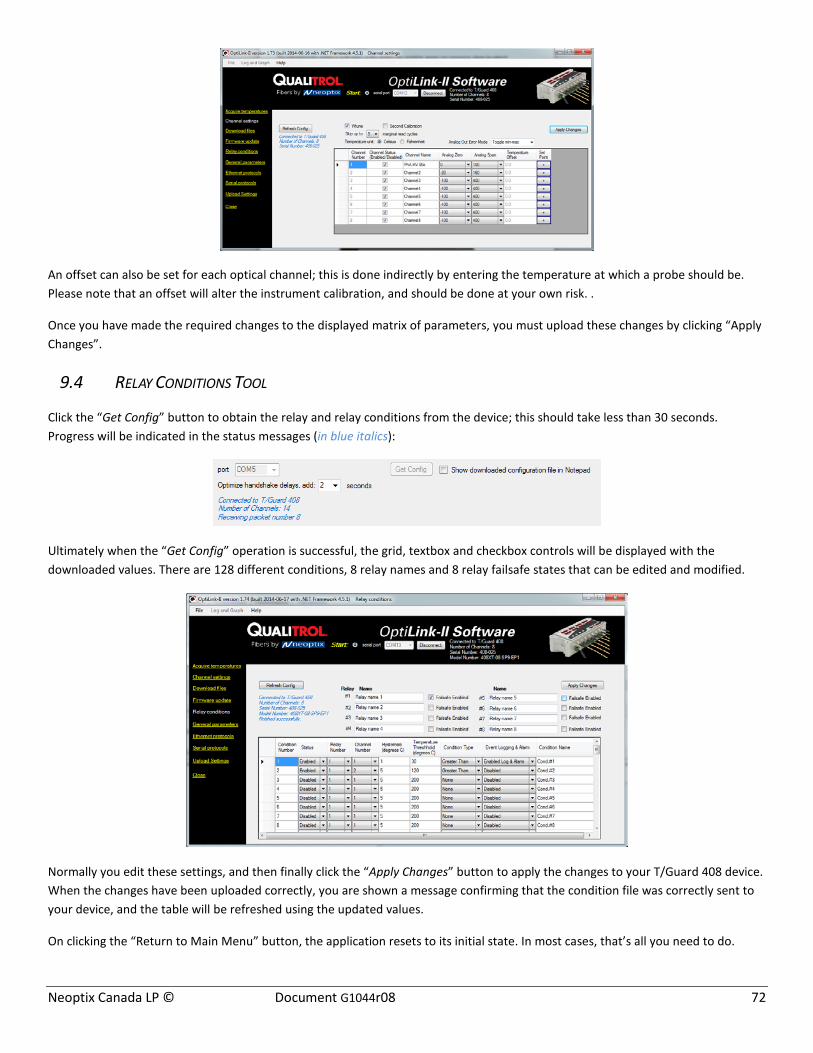
Neoptix Canada LP © Document G1044r08 72
An offset can also be set for each optical channel; this is done indirectly by entering the temperature at which a probe should be. Please note that an offset will alter the instrument calibration, and should be done at your own risk. .
Once you have made the required changes to the displayed matrix of parameters, you must upload these changes by clicking “Apply Changes”.
9.4 RELAY CONDITIONS TOOL
Click the “Get Config” button to obtain the relay and relay conditions from the device; this should take less than 30 seconds. Progress will be indicated in the status messages (in blue italics):
Ultimately when the “Get Config” operation is successful, the grid, textbox and checkbox controls will be displayed with the downloaded values. There are 128 different conditions, 8 relay names and 8 relay failsafe states that can be edited and modified.
Normally you edit these settings, and then finally click the “Apply Changes” button to apply the changes to your T/Guard 408 device. When the changes have been uploaded correctly, you are shown a message confirming that the condition file was correctly sent to your device, and the table will be refreshed using the updated values.
On clicking the “Return to Main Menu” button, the application resets to its initial state. In most cases, that’s all you need to do.

Neoptix Canada LP © Document G1044r08 73
9.5 DOWNLOAD FILES TOOL
This tool can be very useful to download these types of file:
• Status.txt: This is the status file described elsewhere in this document. It essentially gives an overview of all parameters of your system, that can easily be e-mailed or printed
• Temperatures.tem: This is the current logging file for temperature information. When this files reaches 65,000 lines long, it will be archived using the current date and time as a prefix to generate temperatures.tem file name, and a new temperatures.com file will open.
• Event.log: This is the same as the temperatures.com files, but for event information (alarms). • Logging files, both for temperature and for event; these files are best read with Excel. • Smart protocol related files, for Modbus (modbuspt.txt), DNP3 (dnp3pt.txt), IEC 60870-5 (60870pt.txt) and IEC 61850
(QGateway.cid); these files are text files, and can be read easily with Notepad or WordPad. • Configuration file (.cfg); these files can be used to duplicate configurations from one 408 to another one. Use the “Upload
Settings” tool to transfer these files to a new 408; see section 9.10. • Messages includes information about the Linux operating information, that could be useful for Neoptix support in case of
system malfunction; this file is not intended to be useful for the general users.
This shows the download tool:
When you download a file, its name is fixed. To avoid overwriting a file, it is suggested to rename the previously downloaded file first. Downloading large file can take some time… the download rate is approximately 1 kilobytes per second.
The log files (temperature and event) can be deleted, by right clicking on the file name, and selecting “Delete”.
9.6 GENERAL PARAMETERS
This window allows setting up the time and controlling logging.

Neoptix Canada LP © Document G1044r08 74
9.7 ETHERNET PROTOCOL PARAMETERS
This window allows you to manage the licensed protocols over the Ethernet link. If your protocols are not licensed (product with the “-EP0” option), then this window will give you the option to control the Modbus protocol only. By default, these protocols are stopped, to save processor resources; it is suggested to keep them stopped unless you intend to use them. So at first, this window looks like this:
Once started, you will have more options available, such as id addresses, passwords, etc.; as illustrated here:
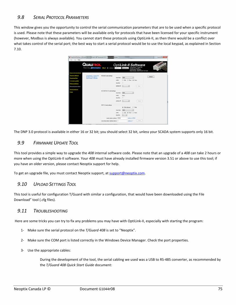
Neoptix Canada LP © Document G1044r08 75
9.8 SERIAL PROTOCOL PARAMETERS
This window gives you the opportunity to control the serial communication parameters that are to be used when a specific protocol is used. Please note that these parameters will be available only for protocols that have been licensed for your specific instrument (however, Modbus is always available). You cannot start these protocols using OptiLink-II, as then there would be a conflict over what takes control of the serial port; the best way to start a serial protocol would be to use the local keypad, as explained in Section 7.10.
The DNP 3.0 protocol is available in either 16 or 32 bit; you should select 32 bit, unless your SCADA system supports only 16 bit.
9.9 FIRMWARE UPDATE TOOL
This tool provides a simple way to upgrade the 408 internal software code. Please note that an upgrade of a 408 can take 2 hours or more when using the OptiLink-II software. Your 408 must have already installed firmware version 3.51 or above to use this tool; if you have an older version, please contact Neoptix support for help.
To get an upgrade file, you must contact Neoptix support, at [email protected].
9.10 UPLOAD SETTINGS TOOL
This tool is useful for configuration T/Guard with similar a configuration, that would have been downloaded using the File Download” tool (.cfg files).
9.11 TROUBLESHOOTING
Here are some tricks you can try to fix any problems you may have with OptiLink-II, especially with starting the program:
1- Make sure the serial protocol on the T/Guard 408 is set to “Neoptix”.
2- Make sure the COM port is listed correctly in the Windows Device Manager. Check the port properties.
3- Use the appropriate cables:
During the development of the tool, the serial cabling we used was a USB to RS-485 converter, as recommended by the T/Guard 408 Quick Start Guide document:

Neoptix Canada LP © Document G1044r08 76
The standard interface on the T/Guard 408 is a RS-485 port, not a RS-232 port. You will probably need a converter, either a RS-232 to RS-485 converter or a USB to RS-485 converter; the latter is recommended (Neoptix part number NXP-343).
Make sure your wiring matches your computer interface. For example, if your wiring is for 4-wires, make sure the whole cabling and software setting are set for full-duplex.
Be careful with cable length, especially when using a RS-232 interface (with a RS-485 to RS-232 converter): under certain circumstances, the baud rate can become as high as 115,000 baud, in which case a RS-232 link would be limited to only a few meters of cable (however, a real RS-485 link would be usable even with cable length of as much as 1 kilometer).
4- Make sure your duplex settings match.
5- Try connecting to the port with a HyperTerminal client to see if it is responsive.
6- This version of OptiLink-II requires that the 408 firmware version be 3.91 or above. If your firmware is older, consider upgrading it. Some functions will crash OptiLink-II if you try to use it with an older firmware version.
7- Try rebooting Windows.
8- Try re-installing your USB to serial port drivers on Windows.
9- When reinstalling OptiLink-II, you must first manually uninstall the current version; this can be done through the Programs and Features facility in Control Panel of Windows.

Neoptix Canada LP © Document G1044r08 77
10 APPENDIX A – SOFTWARE UPGRADE VIA WEB INTERFACE
Firmware update operations are recommended only if there is a functional need that is not met. It is not recommended to upgrade the firmware of a T/Guard 408 for its own sake. Please follow the recommendation of Neoptix Support.
This appendix includes instructions to upgrade a 408XT, with an Ethernet port. If you have a 408 without an Ethernet port, please refer to the previous appendix.
If only for the file transfer speed alone, the web-enabled T/Guard 408 XT should be upgraded via the web page rather than the serial port.
Updates consist of only one file with the suffix .tar.gz and are provided by Neoptix Support. User preferences and network settings are not modified by a firmware update.
To select the provided firmware upload file, click on the 'Browse' button:
This will open a file chooser dialog window. Select the upgrade file provided by Neoptix (.tar.gz) file and click the 'Upload' button.
You will briefly have a progress bar while the file uploads:
This will be followed by a confirmation message:
At this point, there is no turning back. Keep your T/Guard 408 powered on!, as any power interruption may require to send back the unit to Neoptix for reformatting!
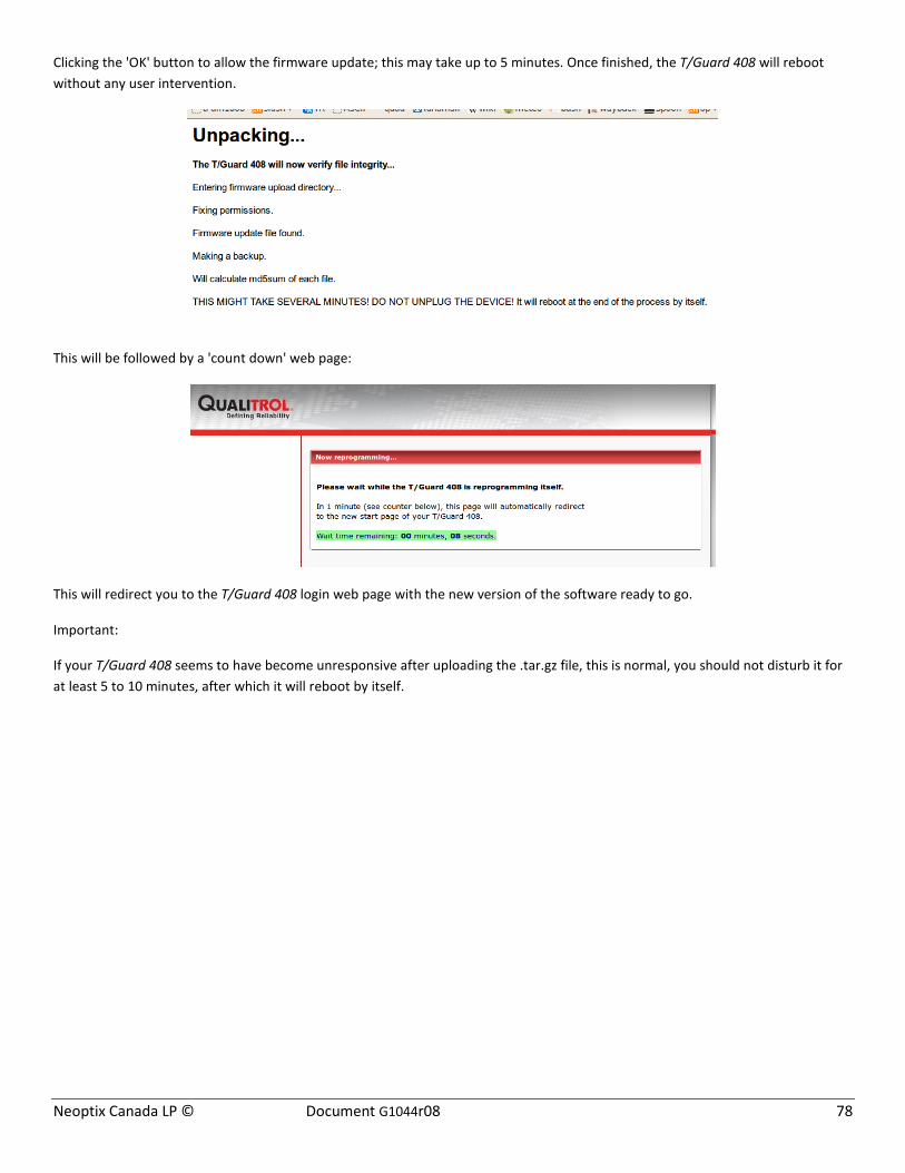
Neoptix Canada LP © Document G1044r08 78
Clicking the 'OK' button to allow the firmware update; this may take up to 5 minutes. Once finished, the T/Guard 408 will reboot without any user intervention.
This will be followed by a 'count down' web page:
This will redirect you to the T/Guard 408 login web page with the new version of the software ready to go.
Important:
If your T/Guard 408 seems to have become unresponsive after uploading the .tar.gz file, this is normal, you should not disturb it for at least 5 to 10 minutes, after which it will reboot by itself.
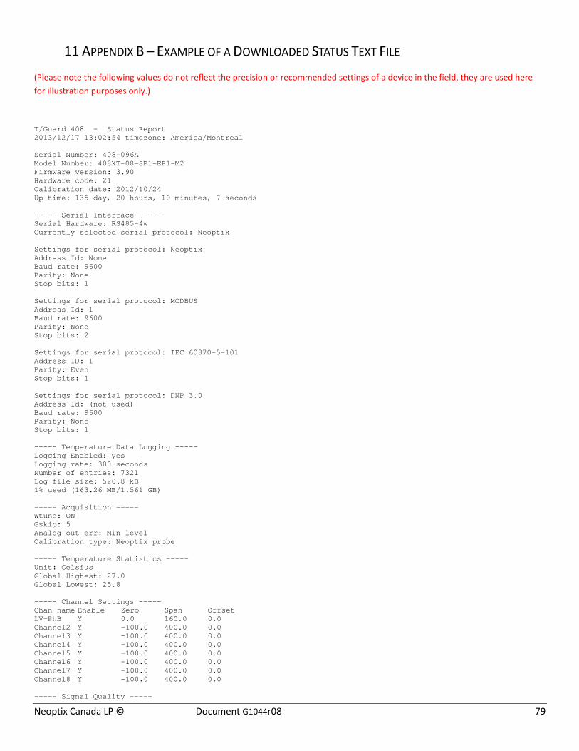
Neoptix Canada LP © Document G1044r08 79
11 APPENDIX B – EXAMPLE OF A DOWNLOADED STATUS TEXT FILE
(Please note the following values do not reflect the precision or recommended settings of a device in the field, they are used here for illustration purposes only.)
T/Guard 408 - Status Report 2013/12/17 13:02:54 timezone: America/Montreal Serial Number: 408-096A Model Number: 408XT-08-SP1-EP1-M2 Firmware version: 3.90 Hardware code: 21 Calibration date: 2012/10/24 Up time: 135 day, 20 hours, 10 minutes, 7 seconds ----- Serial Interface ----- Serial Hardware: RS485-4w Currently selected serial protocol: Neoptix Settings for serial protocol: Neoptix Address Id: None Baud rate: 9600 Parity: None Stop bits: 1 Settings for serial protocol: MODBUS Address Id: 1 Baud rate: 9600 Parity: None Stop bits: 2 Settings for serial protocol: IEC 60870-5-101 Address ID: 1 Parity: Even Stop bits: 1 Settings for serial protocol: DNP 3.0 Address Id: (not used) Baud rate: 9600 Parity: None Stop bits: 1 ----- Temperature Data Logging ----- Logging Enabled: yes Logging rate: 300 seconds Number of entries: 7321 Log file size: 520.8 kB 1% used (163.26 MB/1.561 GB) ----- Acquisition ----- Wtune: ON Gskip: 5 Analog out err: Min level Calibration type: Neoptix probe ----- Temperature Statistics ----- Unit: Celsius Global Highest: 27.0 Global Lowest: 25.8 ----- Channel Settings ----- Chan name Enable Zero Span Offset LV-PhB Y 0.0 160.0 0.0 Channel2 Y -100.0 400.0 0.0 Channel3 Y -100.0 400.0 0.0 Channel4 Y -100.0 400.0 0.0 Channel5 Y -100.0 400.0 0.0 Channel6 Y -100.0 400.0 0.0 Channel7 Y -100.0 400.0 0.0 Channel8 Y -100.0 400.0 0.0 ----- Signal Quality -----
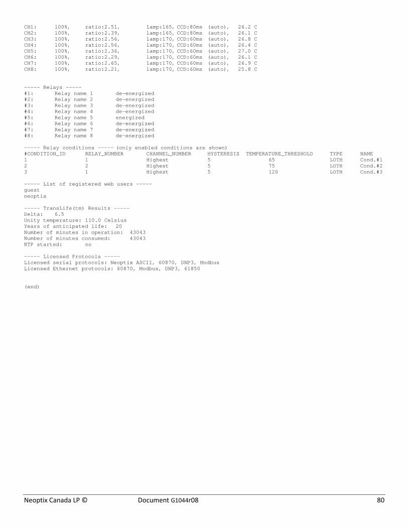
Neoptix Canada LP © Document G1044r08 80
CH1: 100%, ratio:2.51, lamp:165, CCD:80ms (auto), 26.2 C CH2: 100%, ratio:2.39, lamp:165, CCD:80ms (auto), 26.1 C CH3: 100%, ratio:2.56, lamp:170, CCD:60ms (auto), 26.8 C CH4: 100%, ratio:2.56, lamp:170, CCD:60ms (auto), 26.4 C CH5: 100%, ratio:2.36, lamp:170, CCD:60ms (auto), 27.0 C CH6: 100%, ratio:2.29, lamp:170, CCD:60ms (auto), 26.1 C CH7: 100%, ratio:2.65, lamp:170, CCD:60ms (auto), 26.9 C CH8: 100%, ratio:2.21, lamp:170, CCD:60ms (auto), 25.8 C ----- Relays ----- #1: Relay name 1 de-energized #2: Relay name 2 de-energized #3: Relay name 3 de-energized #4: Relay name 4 de-energized #5: Relay name 5 energized #6: Relay name 6 de-energized #7: Relay name 7 de-energized #8: Relay name 8 de-energized ----- Relay conditions ----- (only enabled conditions are shown) #CONDITION_ID RELAY_NUMBER CHANNEL_NUMBER HYSTERESIS TEMPERATURE_THRESHOLD TYPE NAME 1 1 Highest 5 65 LOTH Cond.#1 2 2 Highest 5 75 LOTH Cond.#2 3 1 Highest 5 120 LOTH Cond.#3 ----- List of registered web users ----- guest neoptix ----- TransLife(tm) Results ----- Delta: 6.5 Unity temperature: 110.0 Celsius Years of anticipated life: 20 Number of minutes in operation: 43043 Number of minutes consumed: 43043 NTP started: no ----- Licensed Protocols ----- Licensed serial protocols: Neoptix ASCII, 60870, DNP3, Modbus Licensed Ethernet protocols: 60870, Modbus, DNP3, 61850 (end)
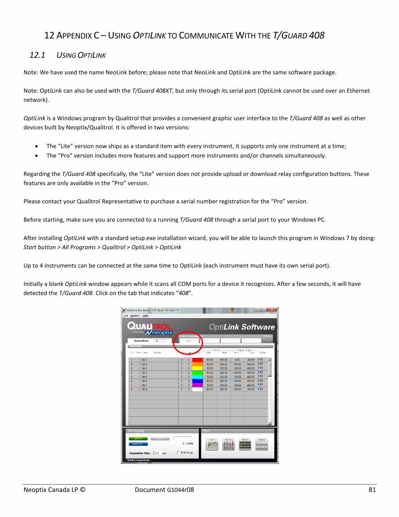
Neoptix Canada LP © Document G1044r08 81
12 APPENDIX C – USING OPTILINK TO COMMUNICATE WITH THE T/GUARD 408
12.1 USING OPTILINK
Note: We have used the name NeoLink before; please note that NeoLink and OptiLink are the same software package. Note: OptiLink can also be used with the T/Guard 408XT, but only through its serial port (OptiLink cannot be used over an Ethernet network). OptiLink is a Windows program by Qualitrol that provides a convenient graphic user interface to the T/Guard 408 as well as other devices built by Neoptix/Qualitrol. It is offered in two versions:
• The “Lite” version now ships as a standard item with every instrument, it supports only one instrument at a time; • The “Pro” version includes more features and support more instruments and/or channels simultaneously.
Regarding the T/Guard 408 specifically, the “Lite” version does not provide upload or download relay configuration buttons. These features are only available in the “Pro” version. Please contact your Qualitrol Representative to purchase a serial number registration for the “Pro” version. Before starting, make sure you are connected to a running T/Guard 408 through a serial port to your Windows PC. After installing OptiLink with a standard setup.exe installation wizard, you will be able to launch this program in Windows 7 by doing: Start button > All Programs > Qualitrol > OptiLink > OptiLink Up to 4 instruments can be connected at the same time to OptiLink (each instrument must have its own serial port). Initially a blank OptiLink window appears while it scans all COM ports for a device it recognizes. After a few seconds, it will have detected the T/Guard 408. Click on the tab that indicates “408”.

Neoptix Canada LP © Document G1044r08 82
This will present the following interface which allows you to change temperature units as well as some other settings in a convenient fashion:
The top portion of the window gives information about the specifics of the thermometer, such as:
• COM Port number • Serial Number of the T/Guard 408 • Calibration date
The On/Off check box allows you to enable or disable a channel. The change is applied as soon as you uncheck a checkbox. Name: Up to 16 characters. You can enter a probe name here that suits your application. This value is not saved to the T/Guard 408 device, it is a convenience provided by OptiLink. The Log checkbox does not refer to the logging made by the T/Guard 408 device itself; it refers to custom logging done on the Windows PC running OptiLink, in the file that is defined in the bottom left corner titled “Data logging”. On the T/Guard 408, logging is an “all or nothing” proposition, while OptiLink offers a more granular control on what is logged. The Chart checkbox allows selecting channels that will be displayed in the popup windows that can be summoned by clicking on one of the four selections in the bottom right “Chart” section. The two “Alarms” settings are once again local to the Windows PC, nothing is forwarded to the T/Guard 408. Here you are allowed to set alarm limits. When one of more alarms are detected, a message is given at the bottom of the main window (must be in Acquisition mode). For a given channel, alarms are monitored only when its corresponding “Chart” or “Log” checkbox is checked, in the Configuration window pane. Alarms are monitored only when Acquisition is active. Analog Outputs: Allows configuring the analog output parameters, Zero and Span. The analog zero is the minimum value of analog output. The analog span can range from 1.0 to 1000.0, in temperature units (Celsius or Fahrenheit). The default values on the T/Guard 408 are -100 for the Zero and 400 for the Span. This is configurable per channel. Under the covers, a change here will send identical commands through the serial port to the T/Guard 408 device as the ASCII Neoptix protocol “s” and “z” commands. Offset: Allows adding an offset to a channel. To perform an offset adjustment:
• Click the "Offset Adjust" button ("+") that is just next to the channel number you want to calibrate.
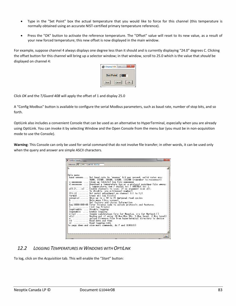
Neoptix Canada LP © Document G1044r08 83
• Type in the "Set Point" box the actual temperature that you would like to force for this channel (this temperature is
normally obtained using an accurate NIST-certified primary temperature reference).
• Press the "OK" button to activate the reference temperature. The "Offset" value will reset to its new value, as a result of your new forced temperature; this new offset is now displayed in the main window.
For example, suppose channel 4 always displays one degree less than it should and is currently displaying “24.0” degrees C. Clicking the offset button for this channel will bring up a selector window; in that window, scroll to 25.0 which is the value that should be displayed on channel 4:
Click OK and the T/Guard 408 will apply the offset of 1 and display 25.0 A “Config Modbus” button is available to configure the serial Modbus parameters, such as baud rate, number of stop bits, and so forth. OptiLink also includes a convenient Console that can be used as an alternative to HyperTerminal, especially when you are already using OptiLink. You can invoke it by selecting Window and the Open Console from the menu bar (you must be in non-acquisition mode to use the Console). Warning: This Console can only be used for serial command that do not involve file transfer; in other words, it can be used only when the query and answer are simple ASCII characters.
12.2 LOGGING TEMPERATURES IN WINDOWS WITH OPTILINK
To log, click on the Acquisition tab. This will enable the “Start” button:

Neoptix Canada LP © Document G1044r08 84
Here you can select the location of the log file and vary the speed of the acquisition rate by clicking on the “Save As…” button. For information, the current filename is displayed just below this button. Default file location is “My Documents”, for Windows 7 and above. The file format of the generated log file will be a plain text file with the .tem file extension. Click the “Start” button to begin logging. Alternately, if you check the “DDE Excel” checkbox, instead of a plain text file as the target, you can log directly to an Excel 2007 spreadsheet instead. Please note, this requires either an English or French language version of Microsoft Excel to be pre-installed on the desktop.
Click the Start button to begin logging. IMPORTANT, the “DDE Excel” functionality requires:
• Either the French or English language versions of Excel to be installed on the Windows 7 PC (note: most international versions of Excel should select English)
• You must correctly identify the language version of Excel when prompted by OptiLink • Click the “.xlsx format” checkbox if you are using Excel version 2007 or later • It is recommended to select a file name for the target spreadsheet that does not exist yet and to close all other open
spreadsheets before beginning • If you select a file name that already exists, data will be appended to the existing data, after a 2 line header has been added

Neoptix Canada LP © Document G1044r08 85
12.3 VIEWING TEMPERATURE DATA IN OPTILINK
Temperature values can be displayed on your computer screen in a number of ways. Click one of the four “Chart” button to active one or more of these windows.
Note that more than one window type can be displayed simultaneously; in addition, you can log temperatures to a file independently from these display windows. Note that each of these 2 modes have each then own acquisition time base. To display temperature trends, click the "Chart" button to get the following window:
Adjust the "Refresh Rate" and Min / Max to suit your viewing needs. The minimum refresh rate is 0.2 second in OptiLink; however the T/Guard 408 will send temperature data once every two seconds. Note that the setting of curve colors and other parameters must be done in the "System Configuration" window pane. Up to 64 trends can be displayed. Displaying analog thermometers can be achieved by clicking the "Thermometer" style button; the following window will appear:
All thermometers share the same Min / Max reading setting. Refresh rate is fixed at 1.0 sec. The size of this window will change depending on the number of channels to display. Up to 16 thermometers can be shown; if you want to display more than 16 channels, only the first 16 detected channels will be shown (note that any channel that has its “Chart” checkbox unchecked, in the main window, will not be shown). If an alarm is active for a channel, the corresponding thermometer numbers will change color: blue for a low temperature alarm, or red for a high temperature alarm.
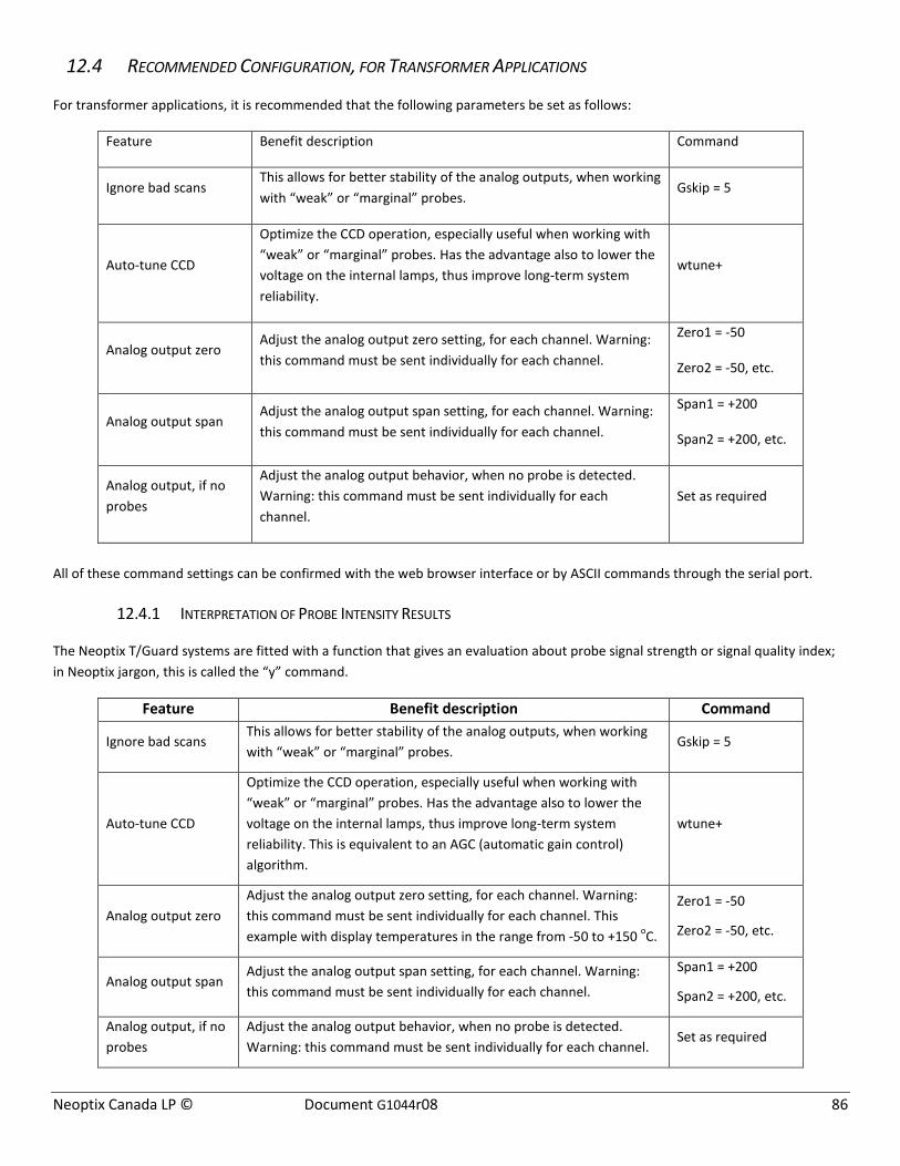
Neoptix Canada LP © Document G1044r08 86
12.4 RECOMMENDED CONFIGURATION, FOR TRANSFORMER APPLICATIONS
For transformer applications, it is recommended that the following parameters be set as follows:
Feature Benefit description Command
Ignore bad scans This allows for better stability of the analog outputs, when working with “weak” or “marginal” probes.
Gskip = 5
Auto-tune CCD
Optimize the CCD operation, especially useful when working with “weak” or “marginal” probes. Has the advantage also to lower the voltage on the internal lamps, thus improve long-term system reliability.
wtune+
Analog output zero Adjust the analog output zero setting, for each channel. Warning: this command must be sent individually for each channel.
Zero1 = -50
Zero2 = -50, etc.
Analog output span Adjust the analog output span setting, for each channel. Warning: this command must be sent individually for each channel.
Span1 = +200
Span2 = +200, etc.
Analog output, if no probes
Adjust the analog output behavior, when no probe is detected. Warning: this command must be sent individually for each channel.
Set as required
All of these command settings can be confirmed with the web browser interface or by ASCII commands through the serial port.
12.4.1 INTERPRETATION OF PROBE INTENSITY RESULTS
The Neoptix T/Guard systems are fitted with a function that gives an evaluation about probe signal strength or signal quality index; in Neoptix jargon, this is called the “y” command.
Feature Benefit description Command
Ignore bad scans This allows for better stability of the analog outputs, when working with “weak” or “marginal” probes.
Gskip = 5
Auto-tune CCD
Optimize the CCD operation, especially useful when working with “weak” or “marginal” probes. Has the advantage also to lower the voltage on the internal lamps, thus improve long-term system reliability. This is equivalent to an AGC (automatic gain control) algorithm.
wtune+
Analog output zero Adjust the analog output zero setting, for each channel. Warning: this command must be sent individually for each channel. This example with display temperatures in the range from -50 to +150 oC.
Zero1 = -50
Zero2 = -50, etc.
Analog output span Adjust the analog output span setting, for each channel. Warning: this command must be sent individually for each channel.
Span1 = +200
Span2 = +200, etc.
Analog output, if no probes
Adjust the analog output behavior, when no probe is detected. Warning: this command must be sent individually for each channel.
Set as required
Neoptix Canada LP © Document G1044r08 87
Typically, the following information is displayed:
CH1: 100%, ratio:2.68, lamp:165, CCD:80, (auto)12
CH1 indicates the channel number (typically 1 to 8, for an 8-channel T/Guard 408 system, or 1 to 16 for a 16-channel system).
The power % value, ranging from 0 to 100%; this parameter is an amalgamation of the 3 parameters (Ratio, Lamp attenuation and CCD time), that simplifies the interpretation of optical signal strength of a probe link. Refer to the Neoptix document G1009, “Probe Installation Guide”, for more information on how to use this global parameter when testing probes.
Ratio indicates the power strength and can span from about +0.3 to +2.8. You can interpret it approximately as follows:
• 0.3 to 1.07: no probe is detected • 1.07 to 1.25: a probe is probably present, but exhibits a very weak signal; its reading is usually rejected, as it is considered
as unreliable • 1.25 to 3.3: a good probe is present (the higher the ratio the more healthy the probe).
Lamp attenuation gives an indication about the white light lamp intensity for this channel. It ranges from 210 (weak lamp) to 100 (strong or intense lamp). A weak lamp is usually preferred and indicates a “healthy” probe.
The CCD time (CCD = charge couple device) gives the optical integration time in millisecond; it can range from 40 to 500 ms. A weak probe will normally have a long integration time.
To summarize, a very good probe is characterized by a good quality index ratio (>1.8), then by a high lamp attenuation (>200) and finally by a short integration time (<200ms). Also, dirty connectors will contribute to lower probe strength; always assure that all fiber connections are clean before evaluating probe performance.
Warning: After a power-on or after changing (or exchanging) probes or extension cords, allow sufficient time for the T/Guard optimization process to complete before invoking the y command; it most cases, it may take as much as 15 seconds for this optimization to complete, especially when the number of enabled channels is high, e.g., 8 or more.
12 The %power value will be displayed only if wtune+ is activated, in which case “(auto)”, instead of “(fixed)”, is also displayed.
Neoptix Canada LP © Document G1044r08 88
13 APPENDIX D – MODBUS COMMUNICATION PROTOCOL
The Modbus protocol is a messaging structure developed by Modicon in 1979, used to establish master-slave / client-server communication between intelligent devices. It is a de-facto standard, truly open and the most widely used network protocol in the industrial manufacturing environment. The Modbus protocol provides an industry standard method that devices can use for parsing messages. The Neoptix T/Guard-408 supports the Modbus protocol over a serial line.
A master-slave type system has one node (the master node) that issues explicit commands to one of the “slave” nodes and processes responses. Slave nodes (such as T/Guard systems: T/Guard, T/Guard+, T/Guard 408, T/Guard-Link, T/Guard 405, etc.) will not transmit data without a request from the master node, and do not communicate with other slaves. Up to 32 units can be connected on a single RS-485 bus.
At the physical level, systems using Modbus over serial lines may employ different physical interfaces, such as RS-485, or RS-232. The RS-485 two-wire interface is the most common. As a standard feature, a RS-485 four-wire interface is fitted on the T/Guard-408 (can be configured by the user as a two-wire interface).
Neoptix has experienced some communication problems when configuring multiple Modbus RS-485 systems together. This is usually caused by unstable grounding problems, such as what can be encountered when dealing with power transformers. To solve these problems, your RS-485 lines should be opto-isolated before connecting them to the master Modbus bus.
13.1 CONFIGURING THE MODBUS OPTION
Configuring and enabling the Modbus option must be done prior to using the protocol; this can be done using the local keypad or with the web interface (408XT only).
The default or suggested parameter values are:
• Stop bit: 1 (fixed)13 • Parity: even • Baud rate (BR): 9,600 (baud rates higher than 19,200 are not recommended) • Address ID: 1 to 247 (each T/Guard must have a unique node address). Addresses ID of 248-255 are also accepted, although
these are not respecting the Modbus protocol.
13.2 SUPPORTED SERIAL TRANSMISSION MODE
The transmission mode defines the bit contents of the message bytes transmitted along the network, and how the message information is to be packed into the message stream and decoded. The current implementation of Neoptix Modbus supports only the RTU mode.
13.3 RTU TRANSMISSION MODE
Coding system 8 bit binary
Number of data bits per character 11 bits start bits –1 data bits – 8 parity bits – 0 or 1(even or odd) stop bits – 1 (2 if no parity bit used)
Parity None or even parity
13 The 408 will allow you to configure it with any combination of stop and parity bits, even if this is not according to the Modbus standard. However, a received character string that does not respect the specified stop and parity bits will be rejected.
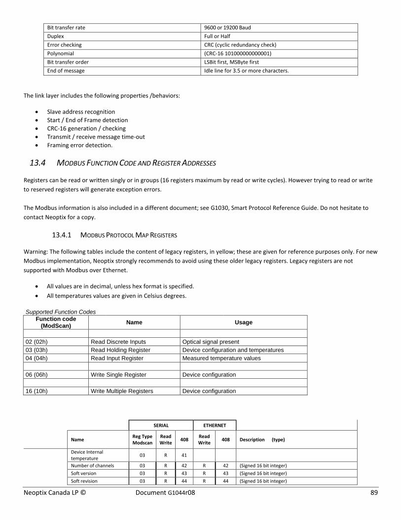
Neoptix Canada LP © Document G1044r08 89
Bit transfer rate 9600 or 19200 Baud Duplex Full or Half Error checking CRC (cyclic redundancy check) Polynomial (CRC-16 101000000000001) Bit transfer order LSBit first, MSByte first End of message Idle line for 3.5 or more characters.
The link layer includes the following properties /behaviors:
• Slave address recognition • Start / End of Frame detection • CRC-16 generation / checking • Transmit / receive message time-out • Framing error detection.
13.4 MODBUS FUNCTION CODE AND REGISTER ADDRESSES
Registers can be read or written singly or in groups (16 registers maximum by read or write cycles). However trying to read or write to reserved registers will generate exception errors. The Modbus information is also included in a different document; see G1030, Smart Protocol Reference Guide. Do not hesitate to contact Neoptix for a copy.
13.4.1 MODBUS PROTOCOL MAP REGISTERS
Warning: The following tables include the content of legacy registers, in yellow; these are given for reference purposes only. For new Modbus implementation, Neoptix strongly recommends to avoid using these older legacy registers. Legacy registers are not supported with Modbus over Ethernet.
• All values are in decimal, unless hex format is specified. • All temperatures values are given in Celsius degrees.
Supported Function Codes Function code
(ModScan) Name Usage
02 (02h) Read Discrete Inputs Optical signal present 03 (03h) Read Holding Register Device configuration and temperatures 04 (04h) Read Input Register Measured temperature values 06 (06h) Write Single Register Device configuration 16 (10h) Write Multiple Registers Device configuration
SERIAL ETHERNET
Name Reg Type Modscan
Read Write 408 Read
Write 408 Description (type)
Device Internal temperature 03 R 41
Number of channels 03 R 42 R 42 (Signed 16 bit integer) Soft version 03 R 43 R 43 (Signed 16 bit integer) Soft revision 03 R 44 R 44 (Signed 16 bit integer)

Neoptix Canada LP © Document G1044r08 90
Device type 03 R 45 R 45 = 17 (for the 408) Mode A 03 R 46 R 46 (Signed 16 bit integer) Mode B 03 R 47 R 47 (Signed 16 bit integer) Power % Powerpct channel 1 03 R 101 R 101 Power % (Signed 16 bit integer) Powerpct channel 2 03 R 102 R 102 Powerpct channel 3 03 R 103 R 103 Powerpct channel 4 03 R 104 R 104 Powerpct channel 5 03 R 105 R 105 Powerpct channel 6 03 R 106 R 106 Powerpct channel 7 03 R 107 R 107 Powerpct channel 8 03 R 108 R 108 Powerpct channel 9 03 R 109 R 109 Powerpct channel 10 03 R 110 R 110 Powerpct channel 11 03 R 111 R 111 Powerpct channel 12 03 R 112 R 112 Powerpct channel 13 03 R 113 R 113 Powerpct channel 14 03 R 114 R 114 Powerpct channel 15 03 R 115 R 115 Powerpct channel 16 03 R 116 R 116 Lamp Lamp attn Channel 1 03 R 201 R 201 Value between 0 and 255 attenuation Lamp attn Channel 2 03 R 202 R 202 Lamp attn Channel 3 03 R 203 R 203 Lamp attn Channel 4 03 R 204 R 204 Lamp attn Channel 5 03 R 205 R 205 Lamp attn Channel 6 03 R 206 R 206 Lamp attn Channel 7 03 R 207 R 207 Lamp attn Channel 8 03 R 208 R 208 Lamp attn Channel 9 03 R 209 R 209 Lamp attn Channel 10 03 R 210 R 210 Lamp attn Channel 11 03 R 211 R 211 Lamp attn Channel 12 03 R 212 R 212 Lamp attn Channel 13 03 R 213 R 213 Lamp attn Channel 14 03 R 214 R 214 Lamp attn Channel 15 03 R 215 R 215 Lamp attn Channel 16 03 R 216 R 216 CCD Time CCD time Channel 1 03 R 301 R 301 Non-auto (wtune-) = 50 CCD time Channel 2 03 R 302 R 302 Auto (wtune+) = 20 to 500, Signed 16 bit integer CCD time Channel 3 03 R 303 R 303 CCD time Channel 4 03 R 304 R 304 CCD time Channel 5 03 R 305 R 305 CCD time Channel 6 03 R 306 R 306 CCD time Channel 7 03 R 307 R 307 CCD time Channel 8 03 R 308 R 308 CCD time Channel 9 03 R 309 R 309 CCD time Channel 10 03 R 310 R 310 CCD time Channel 11 03 R 311 R 311 CCD time Channel 12 03 R 312 R 312 CCD time Channel 13 03 R 313 R 313 CCD time Channel 14 03 R 314 R 314 CCD time Channel 15 03 R 315 R 315 CCD time Channel 16 03 R 316 R 316 Ratio Ratio Channel 1 03 R 401 R 401 Ratio * 100 (Signed 16 bit integer) (signal Ratio Channel 2 03 R 402 R 402 strength) Ratio Channel 3 03 R 403 R 403 Ratio Channel 4 03 R 404 R 404 Ratio Channel 5 03 R 405 R 405

Neoptix Canada LP © Document G1044r08 91
Ratio Channel 6 03 R 406 R 406 Ratio Channel 7 03 R 407 R 407 Ratio Channel 8 03 R 408 R 408 Ratio Channel 9 03 R 409 R 409 Ratio Channel 10 03 R 410 R 410 Ratio Channel 11 03 R 411 R 411 Ratio Channel 12 03 R 412 R 412 Ratio Channel 13 03 R 413 R 413 Ratio Channel 14 03 R 414 R 414 Ratio Channel 15 03 R 415 R 415 Ratio Channel 16 03 R 416 R 416 Analog Analog zero Channel 1 03 R/W 2001 R 2001 Temperature * 10, Signed 16 bit integer zero Analog zero Channel 2 03 R/W 2002 R 2002 Analog zero Channel 3 03 R/W 2003 R 2003 Analog zero Channel 4 03 R/W 2004 R 2004 Analog zero Channel 5 03 R/W 2005 R 2005 Analog zero Channel 6 03 R/W 2006 R 2006 Analog zero Channel 7 03 R/W 2007 R 2007 Analog zero Channel 8 03 R/W 2008 R 2008 Analog zero Channel 9 03 R/W 2009 R 2009 Analog zero Channel 10 03 R/W 2010 R 2010 Analog zero Channel 11 03 R/W 2011 R 2011 Analog zero Channel 12 03 R/W 2012 R 2012 Analog zero Channel 13 03 R/W 2013 R 2013 Analog zero Channel 14 03 R/W 2014 R 2014 Analog zero Channel 15 03 R/W 2015 R 2015 Analog zero Channel 16 03 R/W 2016 R 2016 Analog Analog span Channel 1 03 R/W 2101 R 2101 Temperature * 10, Signed 16 bit integer span Analog span Channel 2 03 R/W 2102 R 2102 Analog span Channel 3 03 R/W 2103 R 2103 Analog span Channel 4 03 R/W 2104 R 2104 Analog span Channel 5 03 R/W 2105 R 2105 Analog span Channel 6 03 R/W 2106 R 2106 Analog span Channel 7 03 R/W 2107 R 2107 Analog span Channel 8 03 R/W 2108 R 2108 Analog span Channel 9 03 R/W 2109 R 2109 Analog span Channel 10 03 R/W 2110 R 2110 Analog span Channel 11 03 R/W 2111 R 2111 Analog span Channel 12 03 R/W 2112 R 2112 Analog span Channel 13 03 R/W 2113 R 2113 Analog span Channel 14 03 R/W 2114 R 2114 Analog span Channel 15 03 R/W 2115 R 2115 Analog span Channel 16 03 R/W 2116 R 2116 Offset Offset Channel 1 03 R/W 2201 R 2201 Temperature * 10, Signed 16 bit integer on channel Offset Channel 2 03 R/W 2202 R 2202 Offset Channel 3 03 R/W 2203 R 2203 Offset Channel 4 03 R/W 2204 R 2204 Offset Channel 5 03 R/W 2205 R 2205 Offset Channel 6 03 R/W 2206 R 2206 Offset Channel 7 03 R/W 2207 R 2207 Offset Channel 8 03 R/W 2208 R 2208 Offset Channel 9 03 R/W 2209 R 2209 Offset Channel 10 03 R/W 2210 R 2210 Offset Channel 11 03 R/W 2211 R 2211 Offset Channel 12 03 R/W 2212 R 2212 Offset Channel 13 03 R/W 2213 R 2213 Offset Channel 14 03 R/W 2214 R 2214

Neoptix Canada LP © Document G1044r08 92
Offset Channel 15 03 R/W 2215 R 2215 Offset Channel 16 03 R/W 2216 R 2216 Enable Enable Channel 1 03 R/W 2301 R 2301 0 = disable ; 1 = enable channel Enable Channel 2 03 R/W 2302 R 2302 Enable Channel 3 03 R/W 2303 R 2303 Enable Channel 4 03 R/W 2304 R 2304 Enable Channel 5 03 R/W 2305 R 2305 Enable Channel 6 03 R/W 2306 R 2306 Enable Channel 7 03 R/W 2307 R 2307 Enable Channel 8 03 R/W 2308 R 2308 Enable Channel 9 03 R/W 2309 R 2309 Enable Channel 10 03 R/W 2310 R 2310 Enable Channel 11 03 R/W 2311 R 2311 Enable Channel 12 03 R/W 2312 R 2312 Enable Channel 13 03 R/W 2313 R 2313 Enable Channel 14 03 R/W 2314 R 2314 Enable Channel 15 03 R/W 2315 R 2315 Enable Channel 16 03 R/W 2316 R 2316 Relay Fail safe Relay 1 03 R/W 2401 R 2401 0 = disable ; 1 = enable failsafe Fail safe Relay 2 03 R/W 2402 R 2402 status Fail safe Relay 3 03 R/W 2403 R 2403 Fail safe Relay 4 03 R/W 2404 R 2404 Fail safe Relay 5 03 R/W 2405 R 2405 Fail safe Relay 6 03 R/W 2406 R 2406 Fail safe Relay 7 03 R/W 2407 R 2407 Fail safe Relay 8 03 R/W 2408 R 2408 Calibration type 03 R/W 2501 R 2501 0 = Neoptix ; 1 = Nortech Fibronic Unit 03 R/W 2502 R 2502 0 = °C ; 1 = °F wtune 03 R/W 2504 R 2504 0 = disable ; 1 = enable (optimize CCD time) Analog out if error 03 R/W 2505 R 2505 0 = max if no signal ; 1 = min if no signal TransLife™ TransLife Delta 03 R R 2601 * 10 (Signed 16 bit integer) TransLife Unity Temp 03 R R 2603 Temperature * 100, Signed 16 bit integer TransLife Years Of Life 03 R R 2605 TransLife Minutes Before 03 R R 2607 TransLife Minutes After 03 R R 2609 Temperature, Channel 1 temperature 04 R 1 R 1 Temperature * 10, Signed 16 bit integer actual Channel 2 temperature 04 R 2 R 2 Channel 3 temperature 04 R 3 R 3 Channel 4 temperature 04 R 4 R 4 Channel 5 temperature 04 R 5 R 5 Channel 6 temperature 04 R 6 R 6 Channel 7 temperature 04 R 7 R 7 Channel 8 temperature 04 R 8 R 8 Channel 9 temperature 04 R 9 R 9 Channel 10 temperature 04 R 10 R 10 Channel 11 temperature 04 R 11 R 11 Channel 12 temperature 04 R 12 R 12 Channel 13 temperature 04 R 13 R 13 Channel 14 temperature 04 R 14 R 14 Channel 15 temperature 04 R 15 R 15 Channel 16 temperature 04 R 16 R 16 R 17 Channel Channel 1 status 02 R 17 R 17 0 = No signal * 1 = Probe detected

Neoptix Canada LP © Document G1044r08 93
status Channel 2 status 02 R 18 R 18 Channel 3 status 02 R 19 R 19 Channel 4 status 02 R 20 R 20 Channel 5 status 02 R 21 R 21 Channel 6 status 02 R 22 R 22 Channel 7 status 02 R 23 R 23 Channel 8 status 02 R 24 R 24 Channel 9 status 02 R 25 R 25 Channel 10 status 02 R 26 R 26 Channel 11 status 02 R 27 R 27 Channel 12 status 02 R 28 R 28 Channel 13 status 02 R 29 R 29 Channel 14 status 02 R 30 R 30 Channel 15 status 02 R 31 R 31 Channel 16 status 02 R 32 R 32 Relay Relay 1 status 02 R 201 R 201 0 = OFF 1 = ON status Relay 2 status 02 R 202 R 202 Relay 3 status 02 R 203 R 203 Relay 4 status 02 R 204 R 204 Relay 5 status 02 R 205 R 205 Relay 6 status 02 R 206 R 206 Relay 7 status 02 R 207 R 207 Relay 8 status 02 R 208 R 208
13.5 MODBUS EXCEPTION CODES
The T/Guard 408 Modbus operation supports 2 exception codes.
Exception code DESCRIPTION 01 Function not supported 02 Register number out of range
If a parity error or CRC error is detected in a received message, the T/Guard 408 simply ignores this message (no response is sent).
13.6 MODSCAN EXAMPLES
ModScan can be purchased from http://www.win-tech.com/html/modscan32.htm. ModScan is a good and simple program that can be used to exercise Modbus links. Furthermore, it can also be used to perform some simple data logging. Please note that this program must be purchased separately, it is not supplied as a standard item with the T/Guard 408 system. See section 13.9 below. When started, the following screen will appear:
Make sure your T/Guard 408 system is connected to your PC computer. Because most PC computers do not have a RS-485 port, you will need a USB to RS-485 adapter (available for purchase as an option from Neoptix).
You must first connect to your PC, by selecting Connection from the main menu, and then Connect.
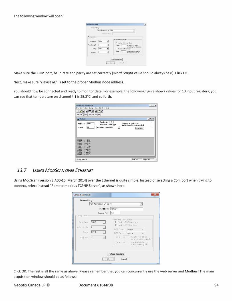
Neoptix Canada LP © Document G1044r08 94
The following window will open:
Make sure the COM port, baud rate and parity are set correctly (Word Length value should always be 8). Click OK.
Next, make sure “Device Id:” is set to the proper Modbus node address.
You should now be connected and ready to monitor data. For example, the following figure shows values for 10 input registers; you can see that temperature on channel # 1 is 25.2oC, and so forth.
13.7 USING MODSCAN OVER ETHERNET
Using ModScan (version 8.A00-10, March 2014) over the Ethernet is quite simple. Instead of selecting a Com port when trying to connect, select instead “Remote modbus TCP/IP Server”, as shown here:
Click OK. The rest is all the same as above. Please remember that you can concurrently use the web server and Modbus! The main acquisition window should be as follows:
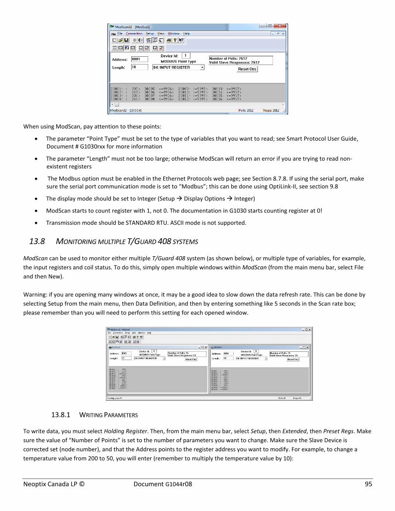
Neoptix Canada LP © Document G1044r08 95
When using ModScan, pay attention to these points:
• The parameter “Point Type” must be set to the type of variables that you want to read; see Smart Protocol User Guide, Document # G1030rxx for more information
• The parameter “Length” must not be too large; otherwise ModScan will return an error if you are trying to read non-existent registers
• The Modbus option must be enabled in the Ethernet Protocols web page; see Section 8.7.8. If using the serial port, make sure the serial port communication mode is set to “Modbus”; this can be done using OptiLink-II, see section 9.8
• The display mode should be set to Integer (Setup Display Options Integer)
• ModScan starts to count register with 1, not 0. The documentation in G1030 starts counting register at 0!
• Transmission mode should be STANDARD RTU. ASCII mode is not supported.
13.8 MONITORING MULTIPLE T/GUARD 408 SYSTEMS
ModScan can be used to monitor either multiple T/Guard 408 system (as shown below), or multiple type of variables, for example, the input registers and coil status. To do this, simply open multiple windows within ModScan (from the main menu bar, select File and then New). Warning: if you are opening many windows at once, it may be a good idea to slow down the data refresh rate. This can be done by selecting Setup from the main menu, then Data Definition, and then by entering something like 5 seconds in the Scan rate box; please remember than you will need to perform this setting for each opened window.
13.8.1 WRITING PARAMETERS
To write data, you must select Holding Register. Then, from the main menu bar, select Setup, then Extended, then Preset Regs. Make sure the value of “Number of Points” is set to the number of parameters you want to change. Make sure the Slave Device is corrected set (node number), and that the Address points to the register address you want to modify. For example, to change a temperature value from 200 to 50, you will enter (remember to multiply the temperature value by 10):
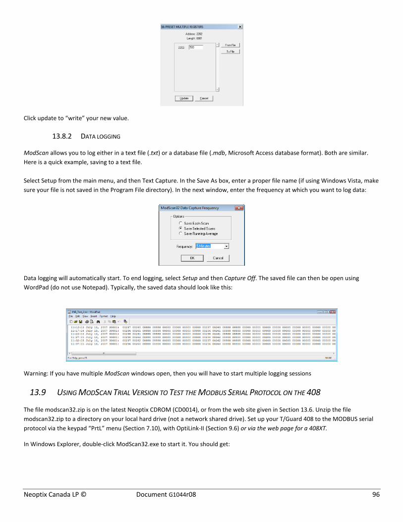
Neoptix Canada LP © Document G1044r08 96
Click update to “write” your new value.
13.8.2 DATA LOGGING
ModScan allows you to log either in a text file (.txt) or a database file (.mdb, Microsoft Access database format). Both are similar. Here is a quick example, saving to a text file. Select Setup from the main menu, and then Text Capture. In the Save As box, enter a proper file name (if using Windows Vista, make sure your file is not saved in the Program File directory). In the next window, enter the frequency at which you want to log data:
Data logging will automatically start. To end logging, select Setup and then Capture Off. The saved file can then be open using WordPad (do not use Notepad). Typically, the saved data should look like this:
Warning: If you have multiple ModScan windows open, then you will have to start multiple logging sessions
13.9 USING MODSCAN TRIAL VERSION TO TEST THE MODBUS SERIAL PROTOCOL ON THE 408
The file modscan32.zip is on the latest Neoptix CDROM (CD0014), or from the web site given in Section 13.6. Unzip the file modscan32.zip to a directory on your local hard drive (not a network shared drive). Set up your T/Guard 408 to the MODBUS serial protocol via the keypad “PrtL” menu (Section 7.10), with OptiLink-II (Section 9.6) or via the web page for a 408XT.
In Windows Explorer, double-click ModScan32.exe to start it. You should get:

Neoptix Canada LP © Document G1044r08 97
Just click the OK button. Next you get:
Wait 3 seconds for the OK button to be enabled then click the OK button. Next you get:
Again, wait 3 seconds for the OK button to be enabled then click the OK button. You get:
Now, we need to customize ModScan. Change settings to the following:

Neoptix Canada LP © Document G1044r08 98
Next, click menu Connection > Connect and set as follows (choose your own COM port of course, according to your PC).
Click the OK button. You should now get:
Click the OK button. You should see values such as the following:
Contact WinTech Software (http://www.win-tech.com/html/modscan32.htm) if you want to purchase this product.

Neoptix Canada LP © Document G1044r08 99
14 APPENDIX E – OPTIONAL RS-485 TO USB CONVERTER
As most PC computers today don’t have serial ports, Neoptix recommends using a RS-485 to USB converter (also called adapter). It works great with all T/Guard, T/Guard 405, T/Guard-Link, T/Guard 408 and T/Guard+ systems. This converter works for both 2W and 4W RS-485 installations; no external power supply is required. It also offers 2000V RMS optical isolation, which is ideal for electrically noisy applications or when grounding may be a problem. The following figure shows this adapter (when purchased from Neoptix, the adapter will be fitted with a DB9 connector suitable for use for both 2W and 4W applications):
Note that this converter requires a special software driver that needs to be installed before you use the device; you will find all details on the CD that comes with the unit. Furthermore, the converter has 4 dip switches that need to be configured depending on your exact installation: there are 2 possibilities, as follows:
a) If you have a 2W (2-wire, also called “half-duplex”) installation, then the four dip switches must be set as follows: a. Switch 1 must be on (RS-485 mode) b. Switch 2 must be on (Echo Off) c. Switch 3 must be on (2 Wire mode) d. Switch 4 must be on (2 Wire mode).
b) If you have a 4W (4-wire, also called “full-duplex”) installation, then the four dip switches must be set as follows:
a. Switch 1 must be on (RS-485 mode) b. Switch 2 must be off (Echo On) c. Switch 3 must be off (4 Wire mode) d. Switch 4 must be off (4 Wire mode).
Warning: When dealing with very long cables (e.g., more than 300 meters), your RS-485 network might need a termination resistor (typically 120Ω). Please consult Neoptix / Qualitrol for more details.

Neoptix Canada LP © Document G1044r08 100
15 APPENDIX F – COMMISSIONING PROCEDURE FOR NEOPTIX T/GUARD-408
15.1 INTRODUCTION
This procedure should be used to confirm the good operation of a Neoptix T/Guard-408 system, which is already installed in a transformer control cabinet; this means that the system is already connected to a suitable 90-260 VAC supply, and has been completely tested by the transformer manufacturer at his manufacturing plant. This procedure is intended to be used by the transformer end user (utility). This procedure should be used in conjunction with the Neoptix applicable documentation, in particular this user guide.
15.2 REQUIRED TOOLS
These tools will be required to perform the procedure completely:
• A PC with a serial port (with a USB adapter) o OptiLink or OptiLink-II software, must be already installed on your PC
These software packages are either on the Neoptix CD or DVD that should have been shipped with the transformer, or you can download them from the web (see instructions below)
o For the 408XT, an Ethernet link and a web browser are highly recommended. In this, case, the OptiLink and OptiLink-II packages are optional
• A milliammeter (milli-ampere-meter), to test the analog outputs.
To perform the procedure in its entirety, a PC computer will be required, along with a proper RS-485 serial interface. Make sure you set your port wiring for either 2-wire (half duplex) or 4-wire (full duplex).
15.3 SOFTWARE DOWNLOADS
These downloads are optional for the 408XT. To perform this procedure completely, you will need either OptiLink or OptiLink-II. The new OptiLink-II software is recommended. Windows Vista or later is required (Windows XP is not supported anymore, sorry). You can download them from the Neoptix website, as follows14:
To download OptiLink, go to web page http://neoptix.com/download.asp and click on the appropriate link. When prompted, enter:
User name: ftp36681896-8
Password: NeolN03?
To download OptiLink-II version 2.4 (for Windows Vista or later), use the same link as above, but select the OptiLink-II link.
Please copy the zip file to a local hard drive and de-compress it before trying to launch the setup.exe.
15.4 TESTING PROBES
We assume here that the utility does not have any spare probes, so we will rely on the probes that are installed in the transformer. The user should know the approximate temperatures inside the transformer; the easiest is to perform this commissioning procedure when the transformer has not had any load for some days, in which case the inside temperature will be approximately the ambient temperature.
Make sure the T/Guard-408 is power on.
14 The software versions indicated below were current at the time of this writing (July 2015). These links should be adapted to other versions as needed.

Neoptix Canada LP © Document G1044r08 101
Confirm that ALL channels display a temperature that is compatible with the current transformer situation. If no display is available for one or more channels (display: - - - -), confirm that the extension cable is connected for this channel, or confirm with the transformer manufacturer that the corresponding probe was working at the factory. It may happen from time to time that a reading is not available on a probe due to damages caused during transformer manufacturing; if this is the case, you will not be able to get a reading for this channel.
15.5 ANALOG OUTPUT TESTING
Note: A milliammeter will be required to test the analog outputs (4 to 20 mA range).
Note: The factory default for analog outputs is “zero = -100 ⁰C” and “span = 400 ⁰C”; If you are not familiar with these 2 parameters, you should read more about it in this user guide. These defaults can be changed to your liking, by using one of the OptiLink software’s.
You can use the milliammeter to read the current for any channels by connecting it to the corresponding 2 connections on the analog output terminal block. For example, assuming the default settings for the analog channels, you should read 9.0 mA for a temperature of 25 ⁰C; if you have the zero set to “0 ⁰C” and the span to “160 ⁰C”, then you should read 6.5 mA, and so forth.
15.6 RELAY TESTING
The relays can be tested in a number of ways. The easiest way to test them is flip their “Fail Safe” mode status. One needs to do this independently for each relay. For the 408XT, this can be via commands using the web server pages; for the 408, use the OptiLink-II software, page 'Relay conditions'. Upon changing the relay status, observe that the corresponding relay is indeed acting appropriately.
15.7 CONCLUSION
This terminates the commissioning procedure. If you have any questions, do not hesitate to contact Neoptix, [email protected].
You can perform other functions with the OptiLink software, such as data logging, Modbus communication settings, etc.; refer to the user guide for more information.
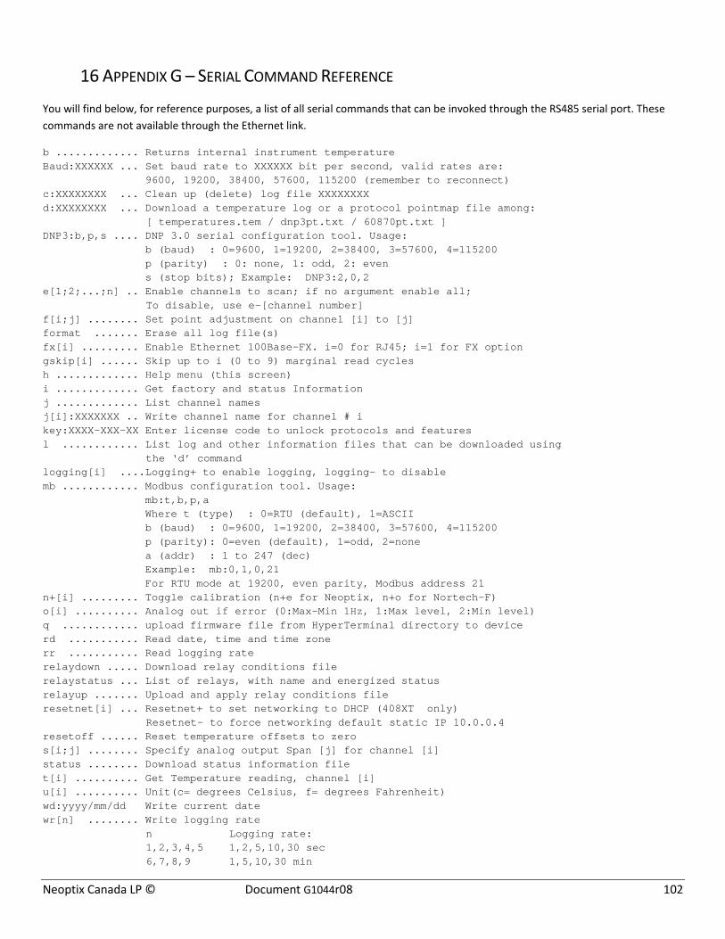
Neoptix Canada LP © Document G1044r08 102
16 APPENDIX G – SERIAL COMMAND REFERENCE
You will find below, for reference purposes, a list of all serial commands that can be invoked through the RS485 serial port. These commands are not available through the Ethernet link.
b ............. Returns internal instrument temperature Baud:XXXXXX ... Set baud rate to XXXXXX bit per second, valid rates are: 9600, 19200, 38400, 57600, 115200 (remember to reconnect) c:XXXXXXXX ... Clean up (delete) log file XXXXXXXX d:XXXXXXXX ... Download a temperature log or a protocol pointmap file among:
[ temperatures.tem / dnp3pt.txt / 60870pt.txt ] DNP3:b,p,s .... DNP 3.0 serial configuration tool. Usage: b (baud) : 0=9600, 1=19200, 2=38400, 3=57600, 4=115200 p (parity) : 0: none, 1: odd, 2: even s (stop bits); Example: DNP3:2,0,2 e[1;2;...;n] .. Enable channels to scan; if no argument enable all;
To disable, use e-[channel number] f[i;j] ........ Set point adjustment on channel [i] to [j] format ....... Erase all log file(s) fx[i] ......... Enable Ethernet 100Base-FX. i=0 for RJ45; i=1 for FX option gskip[i] ...... Skip up to i (0 to 9) marginal read cycles h ............. Help menu (this screen) i ............. Get factory and status Information j ............. List channel names j[i]:XXXXXXX .. Write channel name for channel # i key:XXXX-XXX-XX Enter license code to unlock protocols and features l ............ List log and other information files that can be downloaded using the ‘d’ command logging[i] ....Logging+ to enable logging, logging- to disable mb ............ Modbus configuration tool. Usage: mb:t,b,p,a Where t (type) : 0=RTU (default), 1=ASCII b (baud) : 0=9600, 1=19200, 2=38400, 3=57600, 4=115200 p (parity): 0=even (default), 1=odd, 2=none a (addr) : 1 to 247 (dec) Example: mb:0,1,0,21 For RTU mode at 19200, even parity, Modbus address 21 n+[i] ......... Toggle calibration (n+e for Neoptix, n+o for Nortech-F) o[i] .......... Analog out if error (0:Max-Min 1Hz, 1:Max level, 2:Min level) q ............ upload firmware file from HyperTerminal directory to device rd ........... Read date, time and time zone rr ........... Read logging rate relaydown ..... Download relay conditions file relaystatus ... List of relays, with name and energized status relayup ....... Upload and apply relay conditions file resetnet[i] ... Resetnet+ to set networking to DHCP (408XT only) Resetnet- to force networking default static IP 10.0.0.4 resetoff ...... Reset temperature offsets to zero s[i;j] ........ Specify analog output Span [j] for channel [i] status ........ Download status information file t[i] .......... Get Temperature reading, channel [i] u[i] .......... Unit(c= degrees Celsius, f= degrees Fahrenheit) wd:yyyy/mm/dd Write current date wr[n] ........ Write logging rate n Logging rate: 1,2,3,4,5 1,2,5,10,30 sec 6,7,8,9 1,5,10,30 min
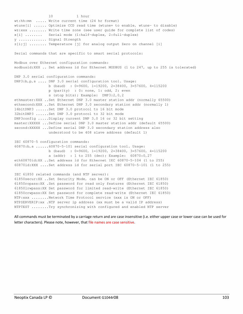
Neoptix Canada LP © Document G1044r08 103
10 1 hour wt:hh:mm ..... Write current time (24 hr format) wtune[i] ...... Optimize CCD read time (wtune+ to enable, wtune- to disable) wz:xxx ........ Write time zone (see user guide for complete list of codes) x[i] ........ Serial mode (1:half-duplex, 2:full-duplex) y ............. Signal Strength z[i;j] ........ Temperature [j] for analog output Zero on channel [i] Serial commands that are specific to smart serial protocols: Modbus over Ethernet configuration commands: modbusid:XXX .. Set address id for Ethernet MODBUS (1 to 247, up to 255 is tolerated) DNP 3.0 serial configuration commands: DNP3:b,p,s .... DNP 3.0 serial configuration tool. Usage: b (baud) : 0=9600, 1=19200, 2=38400, 3=57600, 4=115200 p (parity) : 0: none, 1: odd, 2: even s (stop bits); Example: DNP3:2,0,2 ethmaster:XXX ..Set Ethernet DNP 3.0 master station addr (normally 65500) ethsecond:XXX ..Set Ethernet DNP 3.0 secondary station addr (normally 1) 16bitDNP3 ......Set DNP 3.0 protocol to 16 bit mode 32bitDNP3 ......Set DNP 3.0 protocol to 32 bit mode DNP3config .....Display current DNP 3.0 16 or 32 bit setting master:XXXXX ...Define serial DNP 3.0 master station addr (default 65500) second:XXXXX ...Define serial DNP 3.0 secondary station address also understood to be 408 slave address (default 1) IEC 60870-5 configuration commands: 60870:b,a ......60870-5-101 serial configuration tool. Usage: b (baud) : 0=9600, 1=19200, 2=38400, 3=57600, 4=115200 a (addr) : 1 to 255 (dec); Example: 60870:0,27 eth60870id:XX ..Set address id for Ethernet IEC 60870-5-104 (1 to 255) 60870id:XXX ....Set address id for serial port IEC 60870-5-101 (1 to 255) IEC 61850 related commands (and NTP server): 61850secur:XX ..Set Security Mode, can be ON or OFF (Ethernet IEC 61850) 61850ropass:XX .Set password for read only features (Ethernet IEC 61850) 61850lrwpass:XX Set password for limited read-write (Ethernet IEC 61850) 61850crwpass:XX Set password for complete read-write (Ethernet IEC 61850) NTP:xxx ........Network Time Protocol service (xxx is ON or OFF) NTPSERVERIP:xx .NTP server ip address (xx must be a valid IP address) NTPTEST ........Try synchronizing with configured and enabled NTP server
All commands must be terminated by a carriage return and are case insensitive (i.e. either upper case or lower case can be used for letter characters). Please note, however, that file names are case sensitive.

Neoptix Canada LP © Document G1044r08 104
17 APPENDIX H – TIME ZONE LIST
This list is useful when the serial command « wz » is used; see Section 16 for more details on the « wz » command.
Code Time zone 1 Africa/Abidjan 2 Africa/Accra 3 Africa/Addis Ababa 4 Africa/Algiers 5 Africa/Asmara 6 Africa/Asmera 7 Africa/Bamako 8 Africa/Bangui 9 Africa/Banjul
10 Africa/Bissau 11 Africa/Blantyre 12 Africa/Brazzaville 13 Africa/Bujumbura 14 Africa/Cairo 15 Africa/Casablanca 16 Africa/Ceuta 17 Africa/Conakry 18 Africa/Dakar 19 Africa/Dar es Salaam 20 Africa/Djibouti 21 Africa/Douala 22 Africa/El Aaiun 23 Africa/Freetown 24 Africa/Gaborone 25 Africa/Harare 26 Africa/Johannesburg 27 Africa/Juba 28 Africa/Kampala 29 Africa/Khartoum 30 Africa/Kigali 31 Africa/Kinshasa 32 Africa/Lagos 33 Africa/Libreville 34 Africa/Lome 35 Africa/Luanda 36 Africa/Lubumbashi 37 Africa/Lusaka 38 Africa/Malabo 39 Africa/Maputo 40 Africa/Maseru 41 Africa/Mbabane 42 Africa/Mogadishu 43 Africa/Monrovia 44 Africa/Nairobi 45 Africa/Ndjamena 46 Africa/Niamey 47 Africa/Nouakchott 48 Africa/Ouagadougou 49 Africa/Porto-Novo 50 Africa/Sao Tome 51 Africa/Timbuktu 52 Africa/Tripoli 53 Africa/Tunis 54 Africa/Windhoek 55 America/Adak 56 America/Anchorage 57 America/Anguilla 58 America/Antigua 59 America/Araguaina 60 America/Argentina/Buenos Aires 61 America/Argentina/Catamarca 62 America/Argentina/ComodRivadavia
Code Time zone 63 America/Argentina/Cordoba 64 America/Argentina/Jujuy 65 America/Argentina/La Rioja 66 America/Argentina/Mendoza 67 America/Argentina/Rio Gallegos 68 America/Argentina/Salta 69 America/Argentina/San Juan 70 America/Argentina/San Luis 71 America/Argentina/Tucuman 72 America/Argentina/Ushuaia 73 America/Aruba 74 America/Asuncion 75 America/Atikokan 76 America/Atka 77 America/Bahia 78 America/Bahia Banderas 79 America/Barbados 80 America/Belem 81 America/Belize 82 America/Blanc-Sablon 83 America/Boa Vista 84 America/Bogota 85 America/Boise 86 America/Buenos Aires 87 America/Cambridge Bay 88 America/Campo Grande 89 America/Cancun 90 America/Caracas 91 America/Catamarca 92 America/Cayenne 93 America/Cayman 94 America/Chicago 95 America/Chihuahua 96 America/Coral Harbour 97 America/Cordoba 98 America/Costa Rica 99 America/Creston
100 America/Cuiaba 101 America/Curacao 102 America/Danmarkshavn 103 America/Dawson 104 America/Dawson Creek 105 America/Denver 106 America/Detroit 107 America/Dominica 108 America/Edmonton 109 America/Eirunepe 110 America/El Salvador 111 America/Ensenada 112 America/Fortaleza 113 America/Fort Wayne 114 America/Glace Bay 115 America/Godthab 116 America/Goose Bay 117 America/Grand Turk 118 America/Grenada 119 America/Guadeloupe 120 America/Guatemala 121 America/Guayaquil 122 America/Guyana 123 America/Halifax 124 America/Havana
Code Time zone 125 America/Hermosillo 126 America/Indiana/Indianapolis 127 America/Indiana/Knox 128 America/Indiana/Marengo 129 America/Indiana/Petersburg 130 America/Indiana/Tell City 131 America/Indiana/Vevay 132 America/Indiana/Vincennes 133 America/Indiana/Winamac 134 America/Inuvik 135 America/Iqaluit 136 America/Jamaica 137 America/Jujuy 138 America/Juneau 139 America/Kentucky/Louisville 140 America/Kentucky/Monticello 141 America/Knox IN 142 America/Kralendijk 143 America/La Paz 144 America/Lima 145 America/Los Angeles 146 America/Louisville 147 America/Lower Princes 148 America/Maceio 149 America/Managua 150 America/Manaus 151 America/Marigot 152 America/Martinique 153 America/Matamoros 154 America/Mazatlan 155 America/Mendoza 156 America/Menominee 157 America/Merida 158 America/Metlakatla 159 America/Mexico City 160 America/Miquelon 161 America/Moncton 162 America/Monterrey 163 America/Montevideo 164 America/Montreal 165 America/Montserrat 166 America/Nassau 167 America/New York 168 America/Nipigon 169 America/Nome 170 America/Noronha 171 America/North Dakota/Beulah 172 America/North Dakota/Center 173 America/North Dakota/New Salem 174 America/Ojinaga 175 America/Panama 176 America/Pangnirtung 177 America/Paramaribo 178 America/Phoenix 179 America/Port-au-Prince 180 America/Porto Acre 181 America/Port of Spain 182 America/Porto Velho 183 America/Puerto Rico 184 America/Rainy River 185 America/Rankin Inlet 186 America/Recife

Neoptix Canada LP © Document G1044r08 105
Code Time zone 187 America/Regina 188 America/Resolute 189 America/Rio Branco 190 America/Rosario 191 America/Santa Isabel 192 America/Santarem 193 America/Santiago 194 America/Santo Domingo 195 America/Sao Paulo 196 America/Scoresbysund 197 America/Shiprock 198 America/Sitka 199 America/St Barthelemy 200 America/St Johns 201 America/St Kitts 202 America/St Lucia 203 America/St Thomas 204 America/St Vincent 205 America/Swift Current 206 America/Tegucigalpa 207 America/Thule 208 America/Thunder Bay 209 America/Tijuana 210 America/Toronto 211 America/Tortola 212 America/Vancouver 213 America/Virgin 214 America/Whitehorse 215 America/Winnipeg 216 America/Yakutat 217 America/Yellowknife 218 Antarctica/Casey 219 Antarctica/Davis 220 Antarctica/DumontDUrville 221 Antarctica/Macquarie 222 Antarctica/Mawson 223 Antarctica/McMurdo 224 Antarctica/Palmer 225 Antarctica/Rothera 226 Antarctica/South Pole 227 Antarctica/Syowa 228 Antarctica/Vostok 229 Arctic/Longyearbyen 230 Asia/Aden 231 Asia/Almaty 232 Asia/Amman 233 Asia/Anadyr 234 Asia/Aqtau 235 Asia/Aqtobe 236 Asia/Ashgabat 237 Asia/Ashkhabad 238 Asia/Baghdad 239 Asia/Bahrain 240 Asia/Baku 241 Asia/Bangkok 242 Asia/Beirut 243 Asia/Bishkek 244 Asia/Brunei 245 Asia/Calcutta 246 Asia/Choibalsan 247 Asia/Chongqing 248 Asia/Chungking 249 Asia/Colombo 250 Asia/Dacca 251 Asia/Damascus 252 Asia/Dhaka 253 Asia/Dili 254 Asia/Dubai 255 Asia/Dushanbe 256 Asia/Gaza 257 Asia/Harbin
Code Time zone 258 Asia/Hebron 259 Asia/Ho Chi Minh 260 Asia/Hong Kong 261 Asia/Hovd 262 Asia/Irkutsk 263 Asia/Istanbul 264 Asia/Jakarta 265 Asia/Jayapura 266 Asia/Jerusalem 267 Asia/Kabul 268 Asia/Kamchatka 269 Asia/Karachi 270 Asia/Kashgar 271 Asia/Kathmandu 272 Asia/Katmandu 273 Asia/Kolkata 274 Asia/Krasnoyarsk 275 Asia/Kuala Lumpur 276 Asia/Kuching 277 Asia/Kuwait 278 Asia/Macao 279 Asia/Macau 280 Asia/Magadan 281 Asia/Makassar 282 Asia/Manila 283 Asia/Muscat 284 Asia/Nicosia 285 Asia/Novokuznetsk 286 Asia/Novosibirsk 287 Asia/Omsk 288 Asia/Oral 289 Asia/Phnom Penh 290 Asia/Pontianak 291 Asia/Pyongyang 292 Asia/Qatar 293 Asia/Qyzylorda 294 Asia/Rangoon 295 Asia/Riyadh 296 Asia/Saigon 297 Asia/Sakhalin 298 Asia/Samarkand 299 Asia/Seoul 300 Asia/Shanghai 301 Asia/Singapore 302 Asia/Taipei 303 Asia/Tashkent 304 Asia/Tbilisi 305 Asia/Tehran 306 Asia/Tel Aviv 307 Asia/Thimbu 308 Asia/Thimphu 309 Asia/Tokyo 310 Asia/Ujung Pandang 311 Asia/Ulaanbaatar 312 Asia/Ulan Bator 313 Asia/Urumqi 314 Asia/Vientiane 315 Asia/Vladivostok 316 Asia/Yakutsk 317 Asia/Yekaterinburg 318 Asia/Yerevan 319 Atlantic/Azores 320 Atlantic/Bermuda 321 Atlantic/Canary 322 Atlantic/Cape Verde 323 Atlantic/Faeroe 324 Atlantic/Faroe 325 Atlantic/Jan Mayen 326 Atlantic/Madeira 327 Atlantic/Reykjavik 328 Atlantic/South Georgia
Code Time zone 329 Atlantic/Stanley 330 Atlantic/St Helena 331 Australia/ACT 332 Australia/Adelaide 333 Australia/Brisbane 334 Australia/Broken Hill 335 Australia/Canberra 336 Australia/Currie 337 Australia/Darwin 338 Australia/Eucla 339 Australia/Hobart 340 Australia/LHI 341 Australia/Lindeman 342 Australia/Lord Howe 343 Australia/Melbourne 344 Australia/North 345 Australia/NSW 346 Australia/Perth 347 Australia/Queensland 348 Australia/South 349 Australia/Sydney 350 Australia/Tasmania 351 Australia/Victoria 352 Australia/West 353 Australia/Yancowinna 354 Brazil/Acre 355 Brazil/DeNoronha 356 Brazil/East 357 Brazil/West 358 Canada/Atlantic 359 Canada/Central 360 Canada/Eastern 361 Canada/East-Saskatchewan 362 Canada/Mountain 363 Canada/Newfoundland 364 Canada/Pacific 365 Canada/Saskatchewan 366 Canada/Yukon 367 Chile/Continental 368 Chile/EasterIsland 369 Cuba 370 Egypt 371 Eire 373 Europe/Amsterdam 374 Europe/Andorra 375 Europe/Athens 376 Europe/Belfast 377 Europe/Belgrade 378 Europe/Berlin 379 Europe/Bratislava 380 Europe/Brussels 381 Europe/Bucharest 382 Europe/Budapest 383 Europe/Chisinau 384 Europe/Copenhagen 385 Europe/Dublin 386 Europe/Gibraltar 387 Europe/Guernsey 388 Europe/Helsinki 389 Europe/Isle of Man 390 Europe/Istanbul 391 Europe/Jersey 392 Europe/Kaliningrad 393 Europe/Kiev 394 Europe/Lisbon 395 Europe/Ljubljana 396 Europe/London 397 Europe/Luxembourg 398 Europe/Madrid 399 Europe/Malta 400 Europe/Mariehamn

Neoptix Canada LP © Document G1044r08 106
Code Time zone 401 Europe/Minsk 402 Europe/Monaco 403 Europe/Moscow 404 Europe/Nicosia 405 Europe/Oslo 406 Europe/Paris 407 Europe/Podgorica 408 Europe/Prague 409 Europe/Riga 410 Europe/Rome 411 Europe/Samara 412 Europe/San Marino 413 Europe/Sarajevo 414 Europe/Simferopol 415 Europe/Skopje 416 Europe/Sofia 417 Europe/Stockholm 418 Europe/Tallinn 419 Europe/Tirane 420 Europe/Tiraspol 421 Europe/Uzhgorod 422 Europe/Vaduz 423 Europe/Vatican 424 Europe/Vienna 425 Europe/Vilnius 426 Europe/Volgograd 427 Europe/Warsaw 428 Europe/Zagreb 429 Europe/Zaporozhye 430 Europe/Zurich 431 GB 432 GB-Eire 433 Greenwich 434 Hongkong 435 Iceland 436 Indian/Antananarivo 437 Indian/Chagos 438 Indian/Christmas 439 Indian/Cocos 440 Indian/Comoro 441 Indian/Kerguelen 442 Indian/Mahe 443 Indian/Maldives 444 Indian/Mauritius 445 Indian/Mayotte 446 Indian/Reunion 447 Iran 448 Israel 449 Jamaica 450 Japan 451 Kwajalein 452 Libya 453 Mexico/BajaNorte 454 Mexico/BajaSur 455 Mexico/General 456 Navajo
Code Time zone 457 NZ 458 NZ-CHAT 459 Pacific/Apia 460 Pacific/Auckland 461 Pacific/Chatham 462 Pacific/Chuuk 463 Pacific/Easter 464 Pacific/Efate 465 Pacific/Enderbury 466 Pacific/Fakaofo 467 Pacific/Fiji 468 Pacific/Funafuti 469 Pacific/Galapagos 470 Pacific/Gambier 471 Pacific/Guadalcanal 472 Pacific/Guam 473 Pacific/Honolulu 474 Pacific/Johnston 475 Pacific/Kiritimati 476 Pacific/Kosrae 477 Pacific/Kwajalein 478 Pacific/Majuro 479 Pacific/Marquesas 480 Pacific/Midway 481 Pacific/Nauru 482 Pacific/Niue 483 Pacific/Norfolk 484 Pacific/Noumea 485 Pacific/Pago Pago 486 Pacific/Palau 487 Pacific/Pitcairn 488 Pacific/Pohnpei 489 Pacific/Ponape 490 Pacific/Port Moresby 491 Pacific/Rarotonga 492 Pacific/Saipan 493 Pacific/Samoa 494 Pacific/Tahiti 495 Pacific/Tarawa 496 Pacific/Tongatapu 497 Pacific/Truk 498 Pacific/Wake 499 Pacific/Wallis 500 Pacific/Yap 501 Poland 502 Portugal 503 Singapore 504 Turkey 505 US/Alaska 506 US/Aleutian 507 US/Arizona 508 US/Central 509 US/Eastern 510 US/East-Indiana 511 US/Hawaii 512 US/Indiana-Starke
Code Time zone 513 US/Michigan 514 US/Mountain 515 US/Pacific 516 US/Pacific-New 517 US/Samoa 518 Etc/Zulu 520 CET 521 CST6CDT 522 EET 523 EST 524 EST5EDT 525 HST 526 MET 527 MST 528 MST7MDT 529 PRC 530 PST8PDT 531 ROC 532 ROK 533 WET 534 W-SU 537 Etc/GMT 538 Etc/GMT0 539 Etc/GMT-0 540 Etc/GMT+0 541 Etc/GMT-1 542 Etc/GMT+1 543 Etc/GMT-10 544 Etc/GMT+10 545 Etc/GMT-11 546 Etc/GMT+11 547 Etc/GMT-12 548 Etc/GMT+12 549 Etc/GMT-13 550 Etc/GMT-14 551 Etc/GMT-2 552 Etc/GMT+2 553 Etc/GMT-3 554 Etc/GMT+3 555 Etc/GMT-4 556 Etc/GMT+4 557 Etc/GMT-5 558 Etc/GMT+5 559 Etc/GMT-6 560 Etc/GMT+6 561 Etc/GMT-7 562 Etc/GMT+7 563 Etc/GMT-8 564 Etc/GMT+8 565 Etc/GMT-9 566 Etc/GMT+9 567 Etc/UCT 568 Etc/Universal 569 Etc/UTC
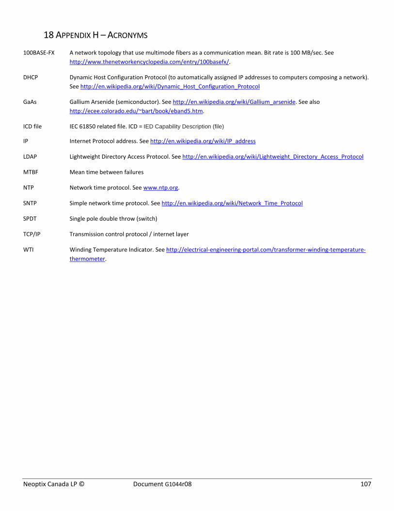
Neoptix Canada LP © Document G1044r08 107
18 APPENDIX H – ACRONYMS
100BASE-FX A network topology that use multimode fibers as a communication mean. Bit rate is 100 MB/sec. See http://www.thenetworkencyclopedia.com/entry/100basefx/.
DHCP Dynamic Host Configuration Protocol (to automatically assigned IP addresses to computers composing a network). See http://en.wikipedia.org/wiki/Dynamic_Host_Configuration_Protocol
GaAs Gallium Arsenide (semiconductor). See http://en.wikipedia.org/wiki/Gallium_arsenide. See also http://ecee.colorado.edu/~bart/book/eband5.htm.
ICD file IEC 61850 related file. ICD = IED Capability Description (file) IP Internet Protocol address. See http://en.wikipedia.org/wiki/IP_address
LDAP Lightweight Directory Access Protocol. See http://en.wikipedia.org/wiki/Lightweight_Directory_Access_Protocol
MTBF Mean time between failures
NTP Network time protocol. See www.ntp.org.
SNTP Simple network time protocol. See http://en.wikipedia.org/wiki/Network_Time_Protocol
SPDT Single pole double throw (switch)
TCP/IP Transmission control protocol / internet layer
WTI Winding Temperature Indicator. See http://electrical-engineering-portal.com/transformer-winding-temperature-thermometer.
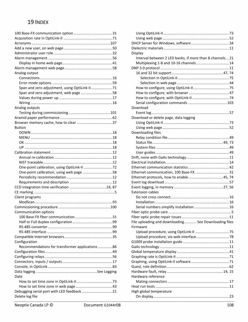
Neoptix Canada LP © Document G1044r08 108
19 INDEX
100 Base-FX communication option ...................................... 31 Acquisition rate in OptiLink-II ................................................ 71 Acronyms ............................................................................. 107 Add a new user, on web page ................................................ 50 Administrator user role .......................................................... 32 Alarm management ............................................................... 56
Display in home web page ................................................. 41 Alarm management web page ............................................... 58 Analog output
Connections ....................................................................... 16 Error mode options ........................................................... 59 Span and zero adjustment, using OptiLink-II ..................... 71 Span and zero adjustment, web page ............................... 58 Values during power up..................................................... 17 Wiring ................................................................................ 16
Analog outputs Testing during commissioning ......................................... 101
Aramid paper performance ................................................... 62 Browser memory cache, how to clear ................................... 37 Button
DOWN ................................................................................ 18 MENU ................................................................................ 18 OK ...................................................................................... 18 UP ...................................................................................... 18
Calibration statement ............................................................ 12 Annual re-calibration ......................................................... 12 NIST traceable.................................................................... 12 One-point calibration, using OptiLink-II ............................ 72 One-point calibration, using web page ............................. 58 Periodicity recommendation ............................................. 12 Requirements and description .......................................... 12
CCD integration time verification .................................... 24, 87 CE marking ............................................................................... 5 Client programs
ModScan ............................................................................ 93 Commissioning procedure ................................................... 100 Communication options
100 Base-FX fiber communication ..................................... 31 Half or Full duplex configuration ....................................... 99 RS-485 converter ............................................................... 99 RS-485 interface ................................................................ 99
Compatible Internet browsers ............................................... 35 Configuration
Recommendations for transformer applications .............. 86 Configuration files .................................................................. 49 Configuring relays .................................................................. 56 Connectors, inputs / outputs ................................................. 17 Console, in OptiLink ............................................................... 83 Data logging ............................................................ See Logging Date
How to set time zone in OptiLink-II ................................... 73 How to set time zone in web page .................................... 43
Debugging serial port with LED feedback .............................. 21 Delete log file
Using OptiLink-II ................................................................ 73 Using web page ................................................................. 52
DHCP Server for Windows, software ..................................... 34 Dielectric materials ................................................................ 11 Display
Interval between 2 LED banks, if more than 8 channels ... 21 Multiplexing 1-8 and 10-16 channels ................................ 14
DNP 3.0 protocol ................................................................... 11 16 and 32 bit support .................................................. 47, 74
Selection in OptiLink-II .................................................. 75 Selection in web page ................................................... 44
How to configure, using OptiLink-II ................................... 75 How to configure, with browser ....................................... 47 How to configure, with OptiLink-II .................................... 74 Serial configuration commands ...................................... 103
Download Event log ............................................................................ 57
Download or delete page, data logging Using OptiLink-II ................................................................ 73 Using web page ................................................................. 52
Downloading files Relay condition file ............................................................ 49 Status file ..................................................................... 49, 73 System files ....................................................................... 49 User guides ........................................................................ 49
Drift, none with GaAs technology.......................................... 11 Electrical installation.............................................................. 14 Ethernet communication statistics ........................................ 42 Ethernet communication, 100 Base-FX ................................. 31 Ethernet protocols, how to enable .................................. 45, 74 Event log download ............................................................... 57 Event logging, in memory ................................................ 27, 56 Extension cables
Do not cross connect ......................................................... 16 Installation ......................................................................... 16 Serial numbers simplify installation .................................. 16
Fiber optic probe care ............................................................. 5 Fiber optic probe repair issues .............................................. 11 File uploading and downloading ............ See Downloading files Firmware
Upload procedure, using OptiLink-II ................................. 75 Upload procedure, via web interface ................................ 78
G1009 probe installation guide ............................................. 11 GaAs technology .................................................................... 11 Global temperature display ................................................... 41 Graphing rate is OptiLink-II .................................................... 71 Graphing, using OptiLink-II software ..................................... 71 Guest, role definition ............................................................. 62 Hardware fault, relay ....................................................... 14, 15 Hardware reference
Mating connectors ............................................................ 17 Heat run tests ........................................................................ 11 High global temperature
On display .......................................................................... 23

Neoptix Canada LP © Document G1044r08 109
On web page ...................................................................... 41 ICD file download, with IEC 61850 ......................................... 47 IEC 60870-5-101 serial protocol ....................................... 48, 75 IEC 60870-5-104 Ethernet protocol ................................. 48, 74 IEC 61850 protocol
How to configure, using OptiLink-II ................................... 74 How to configure, using web page .................................... 46 ICD file download .............................................................. 47 Password management ..................................................... 46
Installation Electrical installation ......................................................... 14 Extension cables ................................................................ 16 Mating connectors (electrical) ........................................... 14 Mating connectors (ST optical inputs) ............................... 15 Mechanical specifications ............................................ 13, 14 ModScan ............................................................................ 93 Mounting on swing panel .................................................. 14 OptiLink ............................................................................. 81 OptiLink-II .......................................................................... 68 RS-422 RS-485 communication converter ......................... 99
Insulation material remaining life .......................................... 60 Internet browsers ............................................................ 35, 37 Interpretation of probe signal intensity ................................. 86 Interval between display of 2 LED banks ............................... 21 IP address
How to set in Windows ..................................................... 33 Static address .................................................................... 33
Kerosene desorption .............................................................. 11 Keypad menu
Channel Enable .................................................................. 24 DNP 3.0 protocol setting ................................................... 29 Entry point ......................................................................... 18 Ethernet menu (408XT only) ............................................. 30 IEC 60870-5-101 protocol setting ...................................... 29 Main (top level) ................................................................. 18 Minimum-maximum temperatures ................................... 23 Modbus protocol setting ................................................... 29 Neoptix ASCII protocol ...................................................... 29 Relay Condition settings .................................................... 26 Relay failsafe setting .......................................................... 27 Second calibration enable ................................................. 21 Serial protocol menu set up .............................................. 28 Setup, general parameters ................................................ 21 Signal level on probes ........................................................ 24 Temperature ...................................................................... 23 Timeout ............................................................................. 18
Kraft paper performance ....................................................... 62 Log download or delete page
Using OptiLink-II ................................................................ 73 Using web page ................................................................. 52
Log setting page ..................................................................... 54 Log viewer page ..................................................................... 53 Logging
In Windows, with OptiLink ................................................ 83 Start of new log file ........................................................... 21 Synchronization time, with NTP server ....................... 43, 73 Using ModScan (Modbus) ................................................. 96
Logging rate in OptiLink-II ...................................................... 71 Low global temperature
On display .......................................................................... 23 On web page ..................................................................... 41
Manage web users ................................................................. 50 Mating connector definition .................................................. 17 Mating connectors (power in and analog outputs) ............... 14 Mating connectors (ST optical inputs) ................................... 15 Menu, via keypad ......................................... See Keypad menu Modbus protocol ................................................................... 11
Configuring, on a serial port .............................................. 88 Exception codes ................................................................ 93 Function Codes and Register Addresses, on serial port .... 89 How to configure, with browser ....................................... 48 How to configure, with OptiLink-II .................................... 74 How to use ModScan over Ethernet ................................. 94 Legacy register support ..................................................... 89 ModScan client application ............................................... 93 Monitoring multiple instruments ...................................... 95 Neoptix support For .......................................................... 88 RS-485 converter ............................................................... 99 RTU serial transmission mode ........................................... 88 RTU Transmission Mode ................................................... 89 Testing RS-485 serial port ................................................. 21
Modify main user role web page ........................................... 51 ModScan
Data logging ...................................................................... 96 How to use for Modbus over Ethernet ............................. 94 Modbus testing ................................................................. 93 Using the trial version ....................................................... 96
MTBF of light source .............................................................. 11 Network configuration .......................................................... 33 NIST traceable calibration...................................................... 12 Nomex paper performance ................................................... 62 NTP servers, for time synchronization
Using OptiLink-II ................................................................ 73 Using web page ................................................................. 43
Offset, on an optical channel Entering with OptiLink-II ................................................... 72 Entering with web page .................................................... 58
Oil immersion ........................................................................ 11 One-point calibration
Using OptiLink-II ................................................................ 72 Using web page ................................................................. 58
Optical channel setting Using OptiLink-II ................................................................ 71 Web page .......................................................................... 58
OptiLink.................................................................................. 81 Chart .................................................................................. 85 Console .............................................................................. 83 Logging to an Excel file ...................................................... 84 Using .................................................................................. 81 Viewing temperature data ................................................ 85
OptiLink-II software pacakge Acquisition vs. Graphing rates ........................................... 71
OptiLink-II software package ................................................. 68 Acquisition vs. Logging rates ............................................. 71
Neoptix Canada LP © Document G1044r08 110
Com port selection ............................................................ 69 Graphing ............................................................................ 71 Logging to an Excel file ...................................................... 70 Option setting .................................................................... 71 Troubleshooting ................................................................ 75 Viewing temperature data ................................................ 69
Options OptiLink-II graphing ........................................................... 71
Overview page Channel parameters ........................................................... 58 Relay conditions ................................................................. 54
Paper performance Aramid paper ..................................................................... 62 Kraft paper ......................................................................... 62 Nomex paper ..................................................................... 62
Period between display of 2 LED banks ................................. 21 POSIX time definition ............................................................. 53 Power consumption ............................................................... 11 Private network configuration ............................................... 33 Probe Installation Guide ........................................................ 11 Probe installation guide, g1009 ............................................. 12 Probe testing
Measuring optical signal strength ..................................... 24 Probes
Extension cable installation ............................................... 15 Installation of extension cables ......................................... 15 Outside connections .......................................................... 16 Testing during commissioning ......................................... 100
Protocol DNP 3.0 protocol setting, with keypad .............................. 29 Enabling Ethernet protocols ........................................ 45, 74 IEC 60870-5-101 protocol setting, with keypad ................ 29 Modbus protocol setting, with keypad ............................. 29 Neoptix ASCII settings, with keypad .................................. 29 Serial protocol enabling, using OptiLink-II ......................... 75 Serial protocol enabling, using web server........................ 44 Switching protocol, using keypad ...................................... 29
Qgateway.icd file download, IEC 61850................................. 47 Quick Startup Guide ............................................................... 13 Real-time clock ....................................................................... 11
NTP servers .................................................................. 43, 73 Relay
Behavior during booting time ............................................ 15 Fail safe mode .................................................................... 54 System fault relay ........................................................ 14, 15 Testing during commissioning ......................................... 101
Relay condition An example ........................................................................ 56 Keypad menu ..................................................................... 27 Setting using OptiLink-II ..................................................... 72 Setting using page, web ..................................................... 55
Relay connection Condition setting ............................................................... 55 Time delay relay ................................................................ 54
Relay setup page .................................................................... 72 Relay trigger ........................................................................... 27 Return Authorization Number (RMA) .................................... 10
RS-232 interface RS-422 RS-485 communication interface .......................... 99 RS-485 to USB converter ................................................... 99
RS-232 to RS-485 converters
Comment on maximum cable length ............................ 76 RS-232 to RS-485 converters ................................................. 99 RS-485 interface .............................................................. 15, 99
Comment on maximum cable length ................................ 76 Testing with LED feedback ................................................ 21 Wiring in half or full duplex ............................................... 29
Serial port Comment on maximum cable length ................................ 76 How to set half or full duplex, using the keypad ............... 21 How to set half or full duplex, using the web interface .... 44 Testing with LED feedback ................................................ 21 Wiring in half or full duplex ............................................... 29
Serial protocol enabling Using OptiLink-II ................................................................ 75 Using web page ................................................................. 44
Signal Strength, how to get using serial commands .............. 86 Smart grid
Ethernet protocols, how to enable ............................. 45, 74 Smart Grid .............................................................................. 11 Software
Apple Safari browser ......................................................... 35 DHCPSVR (DHCP server) .................................................... 34 Download for commissioning .......................................... 100 Google Chrome browser ................................................... 35 Microsoft Internet Explorer browser ................................ 35 ModScan application ......................................................... 93
Using the trial version ................................................... 96 Mozilla Firefox browser ..................................................... 35 OptiLink ............................................................................. 81 OptiLink-II .......................................................................... 68
Software download, for commissioning .............................. 100 Software upgrade
Procedure using OptiLink-II ............................................... 75 Procedure via web interface ............................................. 78
Specifications Input voltage ....................................................................... 5 Mechanical installation ............................................... 13, 14
Statistics, Ethernet communication ....................................... 42 Status information file
Download using OptiLink-II ............................................... 73 Download using web page ................................................ 49 Example of file content ..................................................... 79
System fault relay ............................................................ 14, 15 System label setup ................................................................. 43 TCP/IP Ethernet protocol ....................................................... 11 Temperature acquisition rate in OptiLink-II .......................... 71 Temperature display
Global values ..................................................................... 41 Inside T/Guard enclosure .................................................. 41
Temperature logging .............................................. See Logging Testing serial port with LED feedback ................................... 21 Time
Neoptix Canada LP © Document G1044r08 111
List of time zones ............................................................. 104 NTP server setup, using OptiLink-II.................................... 73 NTP server setup, using web page..................................... 43 Setting up in OptiLink-II ..................................................... 73 Web setup page ................................................................. 43
Time delay relay, for fail safe mode ........................... 14, 15, 54 Time delay relay, to use with the fault relay ................... 14, 15 Time zone
Complete list .................................................................... 104 Setting up in OptiLink-II ..................................................... 73 Web setup page ................................................................. 43
Transformer application Configuration example ...................................................... 56
Transformer application documentation ............................... 12 Transformer applications
Configuration recommendations ...................................... 86 Transformer Life.................................................See TransLife™ TransLife
Web, result page ............................................................... 60 Web, setup page ................................................................ 61
Troubleshooting OptiLink-II .......................................................................... 75
Upload file Configuration file, etc., with web page ............................. 49 Transformer background image file .................................. 60
User guides, how to download .............................................. 49 User management
Guest or Administrator ..................................................... 32 Modify user role, web page .............................................. 51
User management, on web page........................................... 50 Users, how to configure using User Page .............................. 50 Vibration resistance ............................................................... 11 Visual background image file ................................................. 60 Warning
Do not cross-connect extension cables ............................. 16 Offset on optical channel ............................................ 58, 72 Using termination resistors on a RS-485 bus .................... 99 Wiring in half or full duplex ............................................... 29
Warranty Agreement......................................................................... 10 Limitations on probes ........................................................ 10
Web browser ................................................................... 11, 32 Web user management ......................................................... 50 Windows Device Manager ..................................................... 75 WinTech Software ................................................................. 98 Write logging rate .................................................................. 73 Wtune
How to set with OptiLink-II................................................ 72 How to set with the keypad .............................................. 21

Neoptix Canada LP © Document G1044r08 112
Neoptix Canada LP A Qualitrol LLC Company 1415, rue Frank-Carrel, Suite 220 Québec City, QC CANADA G1N 4N7 Tel: 418-687-2500 Fax: 418-687-2524 www.qualitrolcorp.com www.neoptix.com [email protected]
Printed in Canada


![Application Note Transformer Rewind Shops, as a … Note 1 Neoptix Inc. Document # G1025r02 [November 2011] Transformer Rewind Shops, as a potential market for Neoptix Temperature](https://static.fdocuments.us/doc/165x107/5aa25a4d7f8b9a80378ce361/application-note-transformer-rewind-shops-as-a-note-1-neoptix-inc-document.jpg)


