Template for report - BIMMEPAUS · PDF fileBIM-MEPAUS specifications, templates and content...
23
BIM-MEP AUS SPECIFICATION Active Chilled Beams Issued By: BIM-MEP AUS 30 Cromwell Street, Burwood 3205 VIC Australia Revision: REV B Date May 2017
Transcript of Template for report - BIMMEPAUS · PDF fileBIM-MEPAUS specifications, templates and content...
BIM-MEPAUS SPECIFICATION
Active Chilled Beams
Issued By: BIM-MEPAUS
30 Cromwell Street, Burwood 3205 VIC Australia
Revision: REV B
Date May 2017

BIM-MEPAUS Specification
Active Chilled Beam
BIM-MEPAUS
May 2017
Acknowledgements
BIM-MEPAUS greatly acknowledges the contributions of the following organisations to this specification.
• D&E Air Conditioning
• BSA Ltd
• EcoHVAC
• Air conditioning Systems
• A.G. Coombs
• A2K Technologies
• Frenger Systems
• NDY
Formatting conventions
The following table provides the text formats used in BIM-MEPAUS documentation and their application.
Text Type Example Indicates
Italicised text BIM Execution Plan The generic title for a type of document
Bold italicized text BIM-MEPAUS specification The name of a referenced document
Red bold text LOD First reference to a term or abbreviation that is
defined in the website glossary under Practices
Blue text www.bimmepaus.com.au Hyperlink / web link
Blue italicised text Explanatory notes Explanatory notes or reference information
Green bold text Future development Sections or documents that are still under
development by BIM-MEPAUS.
Keeping BIM-MEPAUS up-to-date
BIM-MEPAUS specifications, templates and content are updated to reflect changes in legislation, technology and
industry practice. Feedback and suggestions are welcome and can be made via the BIM-MEPAUS website. Updates
are managed and delivered through the BIM-MEPAUS website.
Liability Disclaimer
BIM-MEPAUS makes no warranty, expressed or implied, including but not limited to any implied warranties of
merchantability and fitness for a particular purpose, nor assumes any legal liability or responsibility for the accuracy,
completeness, or usefulness of the information in this document.
In no event shall BIM-MEPAUS or its agents be liable for damages or losses resulting from your use of, or reliance
on the information provided in this document.
COPYRIGHT © BIM-MEPAUS All rights reserved.

BIM-MEPAUS Specification
Active Chilled Beam
BIM-MEPAUS
May 2017
Table of Contents
1 INTRODUCTION .............................................................................................................. 4
1.1 Scope ........................................................................................................................................................ 4
1.2 BIM-MEPAUS reference documents ............................................................................................................ 4
1.3 Objectives .................................................................................................................................................. 4
1.4 BIM-MEPAUS Schema ................................................................................................................................ 4
2 APPLICABLE STANDARDS ............................................................................................ 5
3 MODELS .......................................................................................................................... 6
3.1 Model workflow .......................................................................................................................................... 6
3.2 Generic design content .............................................................................................................................. 6
3.3 Manufacturer certified content ................................................................................................................... 6
3.4 Commissioned As-Built Model ............................................................................................................... 7
4 SHARED PARAMETER SCHEDULING ........................................................................... 8
5 ACTIVE CHILLED BEAM SPECIFICATION ...................................................................10
5.1 Active chilled beam selection .................................................................................................................. 10
5.2 Active chilled beam installation arrangements ......................................................................................... 10
5.3 Controls ................................................................................................................................................... 10
5.4 Connections ............................................................................................................................................ 10
5.5 Unit Selection .......................................................................................................................................... 10
6 REVIT FUNCTIONALITY ................................................................................................11
6.1 Category classification ............................................................................................................................. 11
6.2 Functional type and sub-type .................................................................................................................. 11
6.3 Family naming syntax .............................................................................................................................. 11
6.4 Family/type version control ...................................................................................................................... 11
6.5 Omniclass ................................................................................................................................................ 12
6.6 Connector settings ................................................................................................................................... 12
6.7 Family geometry ...................................................................................................................................... 13
6.8 Clearance and access zones .................................................................................................................. 13
7 PARAMETER SCHEDULES ...........................................................................................14
7.1 Identity schedule...................................................................................................................................... 14
7.2 BIM classification schedule ..................................................................................................................... 15
7.3 System analysis schedule ....................................................................................................................... 15
7.4 Green building properties schedule ......................................................................................................... 15
7.5 Performance/Quality schedule ................................................................................................................ 16
7.6 Manufacturer schedule ............................................................................................................................ 18
7.7 Commissioning schedule ......................................................................................................................... 18
7.8 Completion schedule ............................................................................................................................... 19
7.9 Generic design model schedule .............................................................................................................. 20
7.10 MCM schedule......................................................................................................................................... 22

BIM-MEPAUS Specification
Active Chilled Beam
BIM-MEPAUS Page 4
May 2017
1 INTRODUCTION
1.1 Scope
This document sets out the BIM-MEPAUS specification for the following families:
• Active Chilled Beams
The following types of Chilled Beams are not addressed in this specification.
• Passive Chilled Beams
1.2 BIM-MEPAUS reference documents
This specification should be read in conjunction with the following specifications and documents:
• BIM-MEPAUS Ducting systems, plant and equipment schedule – this Excel based schedule provides
the complete listing of ductwork systems, plant and equipment names as well as the system colour
schema.
• BIM-MEPAUS Active Chilled Beam product data template – this Excel based schedule details the BMA
IFM and generic design families provided by BIM-MEPAUS including the catalogue of size types provided
for design purposes. The workbook also provides the complete schedule of shared parameters and the
product data templates for designers and product manufacturers.
• BIM-MEPAUS Master shared parameter schedule – this document provides the reference source for all
shared parameter names used within BIM-MEPAUS Generic Design and Manufacturer Certified Model
(MCM) content models together with the Revit MEP classification of each parameter and its associated
BIM-MEPAUS GUID.
• BIM-MEPAUS Plant, equipment and fitting scheduling specification – this document details the
technical and workflow requirements in relation to shared parameter scheduling.
These documents can be accessed through the BIM-MEPAUS website.
1.3 Objectives
Benefits sought through the development and implementation of this BIM-MEPAUS specification include:
• A structured approach to the specification and modelling of active chilled beams;
• Reliable and accurate Design to Commissioned As-built workflows; and
• Industry standardization delivering improved supply chain efficiency and reduced project costs and risks
to the client and project team.
1.4 BIM-MEPAUS Schema
Within the BIM-MEPAUS plant, equipment and fitting schema is used to determine the component life cycle modelling
requirements, active chilled beams are classified as mechanical equipment, sub-classification chilled beams.

BIM-MEPAUS Specification
Active Chilled Beam
BIM-MEPAUS Page 5
May 2017
2 APPLICABLE STANDARDS
There are a number of requirements in the National Construction Code as well as relevant Australian and
international standards that relate to active chilled beam design and selection.
Codes and standards referenced in this specification include:
General Requirements
NCC/ BCA : National Construction Code / Building Code of Australia
AS3500 : National Plumbing and drainage code
State plumbing regulations
Active Chilled Beams
AS 1668.2 -2015 : The use of ventilation and air conditioning in buildings – Part 2: Mechanical
Ventilation in buildings
AS3666 : Air Handling and water systems of buildings – Microbial control
Eurovent : EN15116

BIM-MEPAUS Specification
Active Chilled Beam
BIM-MEPAUS Page 6
May 2017
3 MODELS
3.1 Model workflow
One of the principle aims of BIM-MEPAUS is to enable efficient BIM workflows that see the design model
progressively refined through the design, virtual build and construction process to ultimately deliver a completed
Commissioned As-Built Model.
A key step in this process is the virtual build during which the change-out of the generic design components with
Manufacturer’s Certified Models (MCMs) occurs. These MCMs are able to support a range of construction and
commissioning workflows as well as the asset’s life cycle management post-handover.
The completed construction model generated through the virtual build is then used to drive a range of activities
including site layout, procurement and installation scheduling and tracking.
Once the installation is completed and the systems commissioned, as-built data and project completion information
are used to finalise the Commissioned-As Built Model for handover to the client.
3.2 Generic design content
BIM-MEPAUS generic design families provide a catalogue of sizes (types) that allow designers to spatially model to
LOD 300 as well as specify the active chilled beam’s performance and quality requirements.
The generic design model shared parameters have been developed through industry consultation and are
considered those necessary to schedule the quality and performance requirements for tendering and procurement
purposes.
The standard active chilled beam lengths (mm) are provided in 300mm increments with a minimum length of 600mm
and maximum of 3600mm.
Active beams are also available in standard widths of 300, 500 and 600mm.
Design firms with content libraries can pre-populate these active chilled beam design families with their specific
quality specifications in order to minimise repetitive data entry on each use in a project. This approach limits
subsequent scheduling to only those instance based performance parameters that are typically scheduled in
specification equipment schedules.
3.3 Manufacturer certified content
The virtual build develops the design model into the LOD 400 construction model and typically involves changing
out the design content with manufacturer certified content. Where the manufacturer’s model is BIM-MEPAUS
compliant this should be readily achieved.
Manufacturer’s models are preferably generated from the BIM-MEPAUS Industry Foundation Models (IFM) and
are a single type family that has the active chilled beam geometry needed for the virtual build plus the manufacturer
data for the specific active chilled beam to be supplied to the project.

BIM-MEPAUS Specification
Active Chilled Beam
BIM-MEPAUS Page 7
May 2017
BIM-MEPAUS certified manufacturer models are fully interchangeable with the generic design models and provide:
• Accurate geometry
• Performance data
• Full BIM-MEPAUS Revit operability.
Where the data is not able to be provided by the manufacturer in Revit shared parameter format, manufacturer data
should be delivered in Excel format using the BIM-MEPAUS Product Data Templates to allow the data to be efficiently
imported by the specialist trade contractor into their scheduling database or Revit virtual build model.
Microsoft Excel based product data templates are provided for this purpose on the BIM-MEPAUS website under the
specification product templates section. Where required additional fields can be drawn from the shared parameter
schedules in this specification to provide additional product data as required.
As the MCM and supporting shared parameter schedule replaces the certified drawings and technical schedules
that have traditionally been provided by manufacturers, the model accuracy should be no less than that provided
by a manufacturer’s certified drawing.
Manufacturer’s certified models should preferably include a link to a pdf or web page providing pre-commissioning
checklists for modeller’s and shop drawers to facilitate the proper incorporation of the component into the model as
well as providing the pre-commissioning check sheet for the project site team.
3.4 Commissioned As-Built Model
The commissioned as-built model comprises the construction model updated to reflect any changes made during
the field installation.

BIM-MEPAUS Specification
Active Chilled Beam
BIM-MEPAUS Page 8
May 2017
4 SHARED PARAMETER SCHEDULING
The shared parameter schema has been developed to effectively support data requirements for design,
procurement and commissioning as well as life cycle asset management.
All BIM-MEPAUS plant and equipment models have the same schedule structure shown below.
• Identity
• BIM Classification
• System Analysis
• Green Building Properties
• Performance / Quality
• Manufacturer
• Commissioning
• Completion
System Analysis, Green Building Properties and Commissioning schedules are only included where applicable or
where they have been defined by a relevant standard.
The schedules are progressively completed as the MEP services model progresses through design and virtual
construction to a fully completed Commissioned As-built component within the final model.
Schedule Section Generic Design / MCM
Model schedule
Schedule completion by
Identity Generic design model Designer / Manufacturer / Installer
BIM Classification Generic design model Designer
System Analysis Generic design model Designer
Green Building Properties Generic design model / MCM model Designer / Installer / Manufacturer
Performance /Quality Generic design model / MCM model Designer / Installer
Manufacturer MCM model Manufacturer
Commissioning MCM model Installer
Completion Schedule MCM model Installer
The identity and completion schedules must be completed for all components and once the values are defined are
fixed for the life of the component.
It is expected that not all data will be carried in the Revit design or virtual construction model with non-core data
likely to be managed off model using scheduling databases and/or spreadsheets. This non-core data is commonly
required for the finalization of procurement, commissioning and facility management purposes.
Manufacturer BIM data must be supplied in a format that can be imported into a data management system and/or
Revit based Virtual Construction model with suitable formats including:
• MCM model incorporating BIM-MEPAUS Product Data Template shared parameters
• MCM geometry model with supporting BIM-MEPAUS Product Data Template Excel file.
To allow efficient and reliable data exchanges, it is critical that the BIM-MEPAUS shared parameter names and
respective GUIDs be used.
Parameters indicated in bold font are core Revit model data expected to reside in the model whilst those in italics
are non-core data that can be managed either in the Revit MEP model or off model in a scheduling database.

BIM-MEPAUS Specification
Active Chilled Beam
BIM-MEPAUS Page 9
May 2017
Parameters notated with the symbol have an industry defined set of allowable values or descriptions that are
listed in the master BIM-MEPAUS shared parameter schedule.
It is noted that BIM-MEPAUS compliant manufacturer’s certified models can be used for the basis of design where deemed appropriate by the designer and/or where specific manufacturer plant and equipment is to be nominated.
BIM-MEPAUS Specification
Active Chilled Beam
BIM-MEPAUS Page 10
May 2017
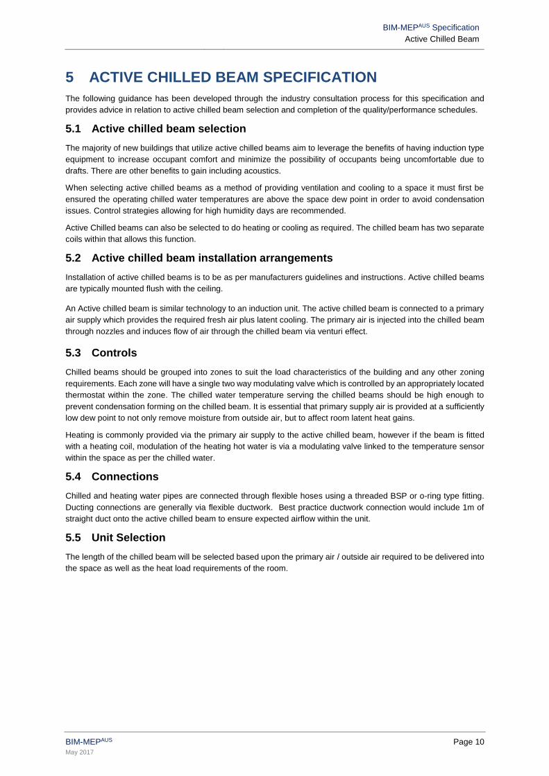
5 ACTIVE CHILLED BEAM SPECIFICATION
The following guidance has been developed through the industry consultation process for this specification and
provides advice in relation to active chilled beam selection and completion of the quality/performance schedules.
5.1 Active chilled beam selection
The majority of new buildings that utilize active chilled beams aim to leverage the benefits of having induction type
equipment to increase occupant comfort and minimize the possibility of occupants being uncomfortable due to
drafts. There are other benefits to gain including acoustics.
When selecting active chilled beams as a method of providing ventilation and cooling to a space it must first be
ensured the operating chilled water temperatures are above the space dew point in order to avoid condensation
issues. Control strategies allowing for high humidity days are recommended.
Active Chilled beams can also be selected to do heating or cooling as required. The chilled beam has two separate
coils within that allows this function.
5.2 Active chilled beam installation arrangements
Installation of active chilled beams is to be as per manufacturers guidelines and instructions. Active chilled beams
are typically mounted flush with the ceiling.
An Active chilled beam is similar technology to an induction unit. The active chilled beam is connected to a primary
air supply which provides the required fresh air plus latent cooling. The primary air is injected into the chilled beam
through nozzles and induces flow of air through the chilled beam via venturi effect.
5.3 Controls
Chilled beams should be grouped into zones to suit the load characteristics of the building and any other zoning
requirements. Each zone will have a single two way modulating valve which is controlled by an appropriately located
thermostat within the zone. The chilled water temperature serving the chilled beams should be high enough to
prevent condensation forming on the chilled beam. It is essential that primary supply air is provided at a sufficiently
low dew point to not only remove moisture from outside air, but to affect room latent heat gains.
Heating is commonly provided via the primary air supply to the active chilled beam, however if the beam is fitted
with a heating coil, modulation of the heating hot water is via a modulating valve linked to the temperature sensor
within the space as per the chilled water.
5.4 Connections
Chilled and heating water pipes are connected through flexible hoses using a threaded BSP or o-ring type fitting.
Ducting connections are generally via flexible ductwork. Best practice ductwork connection would include 1m of
straight duct onto the active chilled beam to ensure expected airflow within the unit.
5.5 Unit Selection
The length of the chilled beam will be selected based upon the primary air / outside air required to be delivered into
the space as well as the heat load requirements of the room.

BIM-MEPAUS Specification
Active Chilled Beam
BIM-MEPAUS Page 11
May 2017
6 REVIT FUNCTIONALITY
6.1 Category classification
All active chilled beam families are designated in Revit MEP as mechanical equipment.
6.2 Functional type and sub-type
The design and manufacture models functional type and sub-type are:
• Functional Type : Mechanical Equipment
• Sub Type : Active Chilled Beam
6.3 Family naming syntax
The Active Chilled Beam family naming convention is as follows
Format:
Generic Design : <Functional Type>_< Sub-Functional Type>_<Generic>_<BMA>
MCM : <Functional Type>_<Sub-Functional Type>_<ManufacturerName>_<Type Descriptor>
Example family names:
Generic Design Model
MechanicalEquipment_ActiveChilledBeam_Generic_BMA
Manufacturer Certified Model
MechanicalEquipment_ActiveChilledBeam_ManufacturerName_ActiveChilledBeam01
6.4 Family/type version control
Family Identification parameters are used for source and version control and are embedded in the Family
Parameters. They do not appear in the BIM-MEPAUS shared parameter schedules for the family as they are not
intended to be modified by designers or constructors.
Design Family – Mutliple Type
Family Identification Unit /Type Sample Value
FamilyName Text Mechanical Equipment_ActiveChilledBeam_ Generic_BMA
Version Text 2016
CreatedOn Text 201607
CreatedBy Text BMA
Manufacturer’s Certified Model – single type
Family Identification Unit /Type Sample Value
FamilyName Text MechanicalEquipment_ActiveChilledBeam_ Manufacturer Name_ ActiveChilledBeam01
TypeName Text QPBA 320
Version Text 2016-01
BIM-MEPAUS Specification
Active Chilled Beam
BIM-MEPAUS Page 12
May 2017
CreatedOn Text 20160831
CreatedBy Text Modelling Company Name
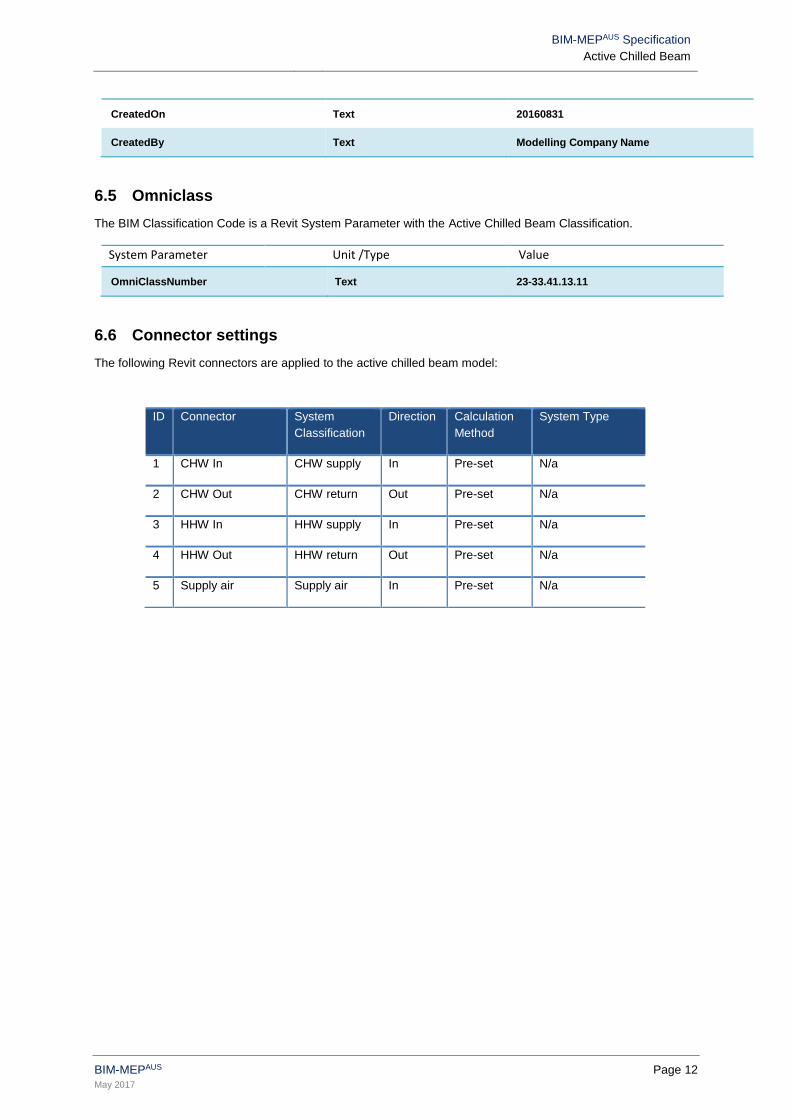
6.5 Omniclass
The BIM Classification Code is a Revit System Parameter with the Active Chilled Beam Classification.
System Parameter Unit /Type Value
OmniClassNumber Text 23-33.41.13.11
6.6 Connector settings
The following Revit connectors are applied to the active chilled beam model:
ID Connector System
Classification
Direction Calculation
Method
System Type
1 CHW In CHW supply In Pre-set N/a
2 CHW Out CHW return Out Pre-set N/a
3 HHW In HHW supply In Pre-set N/a
4 HHW Out HHW return Out Pre-set N/a
5 Supply air Supply air In Pre-set N/a

BIM-MEPAUS Specification
Active Chilled Beam
BIM-MEPAUS Page 13
May 2017
6.7 Family geometry
Family geometry is controlled by type based parameters with the intention that the modeller should not need to
modify the geometry of generic design models or Manufacturer’s Certified Models.
It is noted that the Family Dimension Parameters are used to schedule those parameters that define the type (size
or capacity), with all detailed geometry dimensions listed separately under the Geometry Grouping.
Critical dimensions in relation to the model geometry are:
• Chilled beam length
• Chilled beam width
• Chilled beam depth
• Duct connection
• Pipe Connections
6.8 Clearance and access zones
Clearance zones for maintenance and access are provided for plant and equipment. Manufacturers recommend
300 -1000mm in front of the beam to provide duct and pipe connections.
These requirements can be turned on or off for the purpose of clash coordination exercises.
Fine Level of Detail Plan with clearance and access
zones
Fine Level Detail / Shaded 3D with clearance and access
zones

BIM-MEPAUS Specification
Active Chilled Beam
BIM-MEPAUS Page 14
May 2017
7 PARAMETER SCHEDULES
The schedule structure and parameters have been developed to meet the needs of the BIM-MEPAUS integrated
project delivery workflows as well as support future asset life cycle management requirements. The Product Data
Templates form a subset of the overall shared parameter scheme.
Refer to Section 4 - Shared Parameter Scheduling for a detailed overview of the intended use and application of
the schedules.
Parameter fields indicated in black bold text are included in the Product Data Template with the Design Model
Schedule being provided with a sub-set of these parameters detailed in Section 7.9 Generic Design Model
Schedule.
7.1 Identity schedule
Figure 7.1 Identity schedule
Design parameters Unit / Type Sample Value
ComponentName Text M-ACB-32-2
SystemServed Text M-AHU-40-2
ZoneServed Text West perimeter
Location Text Level 32
ComponentStatus Text CAB
MCM parameters Unit /Type Sample Value
Manufacturer Text Manufacturer Name
Model Text Model Name
ProductCode Text Product Code
SerialNumber Text Serial Number
ManufacturerURL Text Link to product page
AM/FM parameters Unit /Type Sample Value
AssetIdentifier Text M-ACB-32-12
Barcode Text Barcode Number
RFID Text RFID Tag Number

BIM-MEPAUS Specification
Active Chilled Beam
BIM-MEPAUS Page 15
May 2017
7.2 BIM classification schedule
The BIM classification codes are based on the OmniClass Construction Classification System (known as
OmniClass™ or OCCS) for the construction industry and Natspec.
Fig 7.2.1 BIM classification schedule
Parameters Unit /Type Sample Value
OmniClassElementNumber Text 23-33 41 13 11
OmniClassElementName Text Constant Volume Air Induction Terminal Air Units
NATspecWorkSection Text 0748
Detailed definition of Elements can be found at http://www.omniclass.org/tables.asp with the following relevant
codes noted:
NATspec’s Work Section classification system can be found at
www.natspec.com.au/Products_Services/listallworksection.asp .
7.3 System analysis schedule
Figure 7.3.1 System analysis Schedule
Parameter Unit/Type Sample Value
ACBAirFlowCalc L/s 100
DuctSysStaticPressCalc Pa 50
The two calculated figures in the family are returned by the active chilled beam family when placed into the system
– refer to Autodesk documentation for details of the calculation algorithm.
7.4 Green building properties schedule
No green building property parameters are currently defined for active chilled beams.

BIM-MEPAUS Specification
Active Chilled Beam
BIM-MEPAUS Page 16
May 2017
7.5 Performance/Quality schedule
The performance and quality schedule details the performance and quality requirements for the active chilled beam.
The schedule brings together a number of typical specification requirements including those related to active chilled
beam design and performance, mechanical-electrical system integration and vibration and noise isolation.
The Manufacturer’s certified model may overwrite some sections of this schedule replacing the design performance
requirements with submitted performance data.
Figure 7.5.1 Performance / Quality Schedule
Active Chilled Beam Details
Parameter Unit/Type Sample Value
CHB_Type Text ActiveChilledBeam
CHB_Length mm 1200
CHB_Width mm 600
CHB_Depth mm 200
CHB_SupplyAir L/s 100
CHB_PrimaryAir L/s 40
CHB_StaticDutyPress Pa 80
CHB_Model Text ACB46
DuctSizeConnection mm 50
Coil Details
Parameter Unit/Type Sample Value
CoolingCapacitySensible kW 2.1
HeatingCapacity kW 2.1
CHW_TemperatureIn °C 15
CHW_TemperatureOut °C 18
CHW_Flow L/s 0.1
CHW_FlowConnectionSize mm 15
CHW_ReturnConnectionSize mm 15
HHW_TemperatureIn °C 80
HHW_TemperatureOut °C 60
HHW_Flow L/s 0.1
HHW_FlowConnectionSize mm 15
HHW_ReturnConnectionSize mm 15

BIM-MEPAUS Specification
Active Chilled Beam
BIM-MEPAUS Page 17
May 2017
Noise Details
Parameter Unit/Type Sample Value
OutletPWL63Hz dBW 96
OutletPWL125Hz dBW 92
OutletPWL250Hz dBW 94
OutletPWL500Hz dBW 92
OutletPWL1000Hz dBW 90
OutletPWL2000Hz dBW 88
OutletPWL4000Hz dBW 85
OutletPWL8000Hz dBW 81
Basis of Design
Parameter Unit/Type Sample Value
BasisofDesign Text Nominated Manufacturer

BIM-MEPAUS Specification
Active Chilled Beam
BIM-MEPAUS Page 18
May 2017
7.6 Manufacturer schedule
Manufacturer schedules are completed by suppliers to confirm the detailed performance, quality and configuration
selections.
Figure 7.6.1 Manufacturer’s Schedule
Active Chilled Beam Details
Parameter Unit/Type Sample Value
CHB_Model Text ModelName
CHB_SupplyAir L/s 100
CHB_StaticDutyPress Pa 80
CHB_Length mm 1200
CHB_Width mm 600
CHB_Depth mm 200
CoolingCapacitySensible kW 2.1
HeatingCapacity kW 2.1
DuctSizeConnection mm 50
CHW_FlowConnectionSize mm 15
CHW_ReturnConnectionSize mm 15
HHW_FlowConnectionSize mm 15
HHW_ReturnConnectionSize mm 15
Assembly Details
Parameter Unit/Type Sample Value
TotalMass kg 40
PreCommissioningITP URL Link to Manufacturer’s ITP
7.7 Commissioning schedule
Commissioning schedules are based on NEBB and relevant Australian Standards and are to be completed by the
installers commissioning team and/or manufacturer’s representative.
Figure 7.7.1 Commissioning Schedule
Parameter Unit/Type Sample Value
CHB_Model Text ModelName
CHB_SupplyAirActual L/s 100
CHB_PrimaryAirActual L/s 40
CHW_FlowActual L/s 0.1
HHW_FlowActual L/s 0.1
CHB_StaticPress Pa 80
BIM-MEPAUS Specification
Active Chilled Beam
BIM-MEPAUS Page 19
May 2017
CommissioningDate Text 2015-09-16
CommissioningTechName Text Commissioning Tech Name
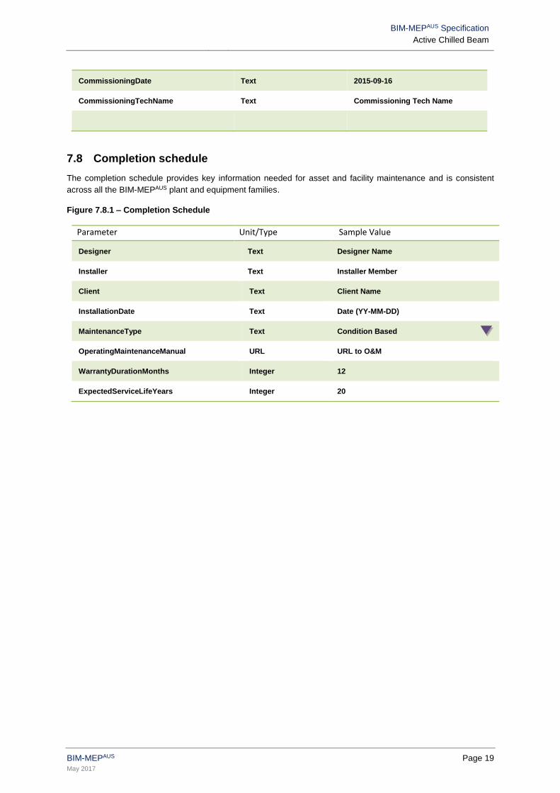
7.8 Completion schedule
The completion schedule provides key information needed for asset and facility maintenance and is consistent
across all the BIM-MEPAUS plant and equipment families.
Figure 7.8.1 – Completion Schedule
Parameter Unit/Type Sample Value
Designer Text Designer Name
Installer Text Installer Member
Client Text Client Name
InstallationDate Text Date (YY-MM-DD)
MaintenanceType Text Condition Based
OperatingMaintenanceManual URL URL to O&M
WarrantyDurationMonths Integer 12
ExpectedServiceLifeYears Integer 20
BIM-MEPAUS Specification
Active Chilled Beam
BIM-MEPAUS Page 20
May 2017
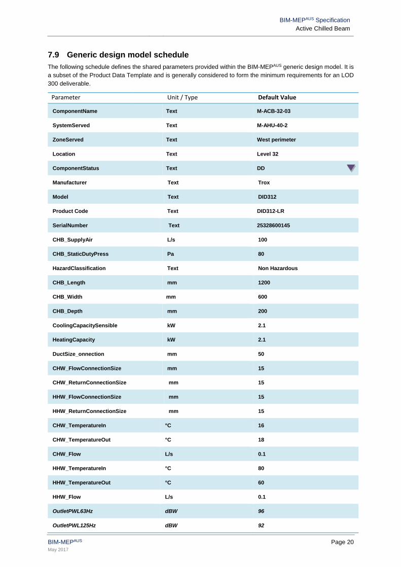
7.9 Generic design model schedule
The following schedule defines the shared parameters provided within the BIM-MEPAUS generic design model. It is
a subset of the Product Data Template and is generally considered to form the minimum requirements for an LOD
300 deliverable.
Parameter Unit / Type Default Value
ComponentName Text M-ACB-32-03
SystemServed Text M-AHU-40-2
ZoneServed Text West perimeter
Location Text Level 32
ComponentStatus Text DD
Manufacturer Text Trox
Model Text DID312
Product Code Text DID312-LR
SerialNumber Text 25328600145
CHB_SupplyAir L/s 100
CHB_StaticDutyPress Pa 80
HazardClassification Text Non Hazardous
CHB_Length mm 1200
CHB_Width mm 600
CHB_Depth mm 200
CoolingCapacitySensible kW 2.1
HeatingCapacity kW 2.1
DuctSize_onnection mm 50
CHW_FlowConnectionSize mm 15
CHW_ReturnConnectionSize mm 15
HHW_FlowConnectionSize mm 15
HHW_ReturnConnectionSize mm 15
CHW_TemperatureIn °C 16
CHW_TemperatureOut °C 18
CHW_Flow L/s 0.1
HHW_TemperatureIn °C 80
HHW_TemperatureOut °C 60
HHW_Flow L/s 0.1
OutletPWL63Hz dBW 96
OutletPWL125Hz dBW 92

BIM-MEPAUS Specification
Active Chilled Beam
BIM-MEPAUS Page 21
May 2017
OutletPWL250Hz dBW 94
OutletPWL500Hz dBW 92
OutletPWL1000Hz dBW 90
OutletPWL2000Hz dBW 88
OutletPWL4000Hz dBW 85
OutletPWL8000Hz dBW 81
SoundPressure@3m dBW 0
BasisofDesign Text Manufacturer Name / Model
Designer Text Designer Name
Client Text Client Name
BIM-MEPAUS Specification
Active Chilled Beam
BIM-MEPAUS Page 22
May 2017
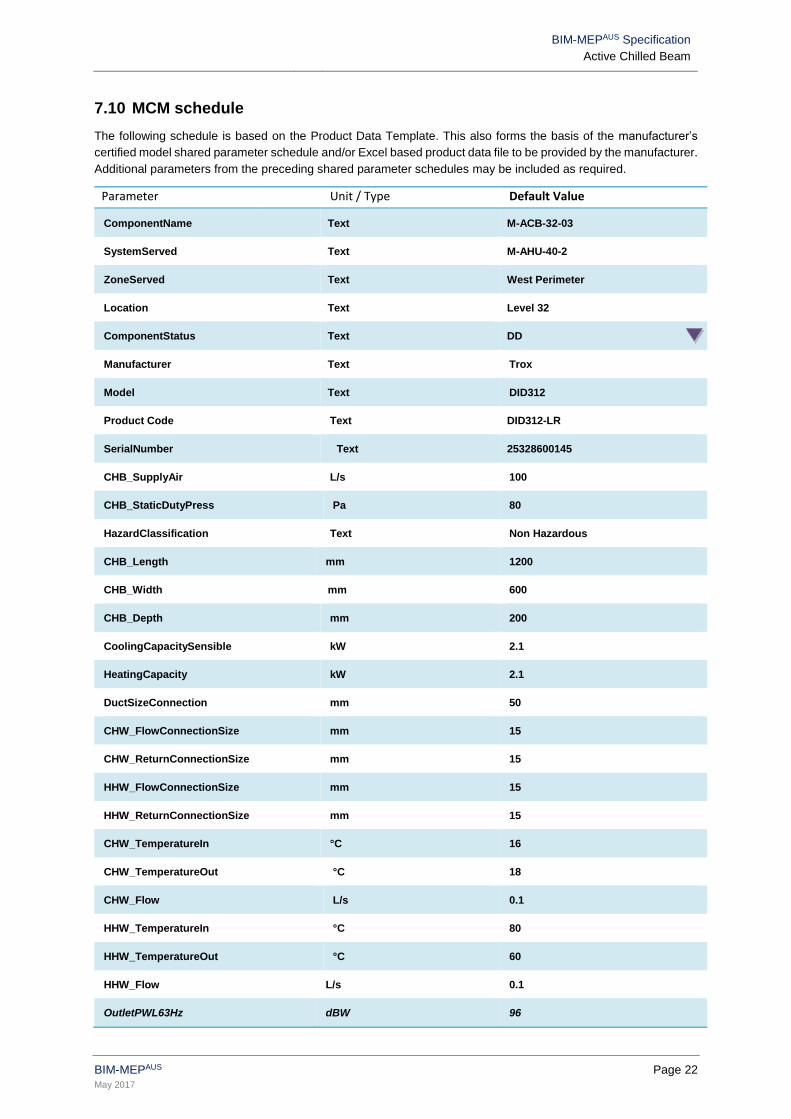
7.10 MCM schedule
The following schedule is based on the Product Data Template. This also forms the basis of the manufacturer’s
certified model shared parameter schedule and/or Excel based product data file to be provided by the manufacturer.
Additional parameters from the preceding shared parameter schedules may be included as required.
Parameter Unit / Type Default Value
ComponentName Text M-ACB-32-03
SystemServed Text M-AHU-40-2
ZoneServed Text West Perimeter
Location Text Level 32
ComponentStatus Text DD
Manufacturer Text Trox
Model Text DID312
Product Code Text DID312-LR
SerialNumber Text 25328600145
CHB_SupplyAir L/s 100
CHB_StaticDutyPress Pa 80
HazardClassification Text Non Hazardous
CHB_Length mm 1200
CHB_Width mm 600
CHB_Depth mm 200
CoolingCapacitySensible kW 2.1
HeatingCapacity kW 2.1
DuctSizeConnection mm 50
CHW_FlowConnectionSize mm 15
CHW_ReturnConnectionSize mm 15
HHW_FlowConnectionSize mm 15
HHW_ReturnConnectionSize mm 15
CHW_TemperatureIn °C 16
CHW_TemperatureOut °C 18
CHW_Flow L/s 0.1
HHW_TemperatureIn °C 80
HHW_TemperatureOut °C 60
HHW_Flow L/s 0.1
OutletPWL63Hz dBW 96

BIM-MEPAUS Specification
Active Chilled Beam
BIM-MEPAUS Page 23
May 2017
OutletPWL125Hz dBW 92
OutletPWL250Hz dBW 94
OutletPWL500Hz dBW 92
OutletPWL1000Hz dBW 90
OutletPWL2000Hz dBW 88
OutletPWL4000Hz dBW 85
OutletPWL8000Hz dBW 81
SoundPressure@3m dBW 0
BasisofDesign Text Manufacturer Name / Model
TotalMass kg 40
CHB_SupplyAirActual L/s 100
CHB_PrimaryAirActual L/s 40
CHW_FlowActual L/s 0.1
HHW_FlowActual L/s 0.1
CHB_StaticPress Pa 80
CommissioningDate Text 2015-09-16
CommissioningTechName Text Commissioning Tech Name
Designer Text Designer Name
Installer Text Installer Member
Client Text Client Name
InstallationDate Text Date (YY-MM-DD)
MaintenanceType Text Condition Based
OperatingMaintenanceManual URL URL to O&M
WarrantyDurationMonths Integer 12
ExpectedServiceLifeYears Integer 20
END