Tema 1: Tecnologías de red. - grc.upv.es · Tema 1: Tecnologías de red. Estructura de Internet...
96
Transmisión de Datos Multimedia – http://www.grc.upv.es/docencia/tdm – Master IC 2007/2008 Tema 1: Tecnologías de red. Tema 1: Tecnologías de red. Estructura de Internet Redes “core” SONET DWDM Redes de acceso Redes cableadas: Ethernet et al. Redes inalámbricas: IEEE 802.11, UMTS et al.
Transcript of Tema 1: Tecnologías de red. - grc.upv.es · Tema 1: Tecnologías de red. Estructura de Internet...

Transmisión de Datos Multimedia – http://www.grc.upv.es/docencia/tdm – Master IC 2007/2008
Tema 1: Tecnologías de red.Tema 1: Tecnologías de red.
�Estructura de Internet
�Redes “core”� SONET
� DWDM
�Redes de acceso� Redes cableadas: Ethernet et al.
� Redes inalámbricas: IEEE 802.11, UMTS et al.

Tra
nsm
isió
n d
e D
ato
s M
ultim
edia
-M
ast
er
IC 2
007/2
008
2
What’s the Internet: “nuts and bolts” view
� End systems
� Host computer
� Network applications
� Access networks
� Local area networks
� communication links
� Network core:
� routers
� network of networks
local ISP
companynetwork
regional ISP
router workstation
servermobile
Tra
nsm
isió
n d
e D
ato
s M
ultim
edia
-M
ast
er
IC 2
007/2
008
3
Internet structure: network of networks
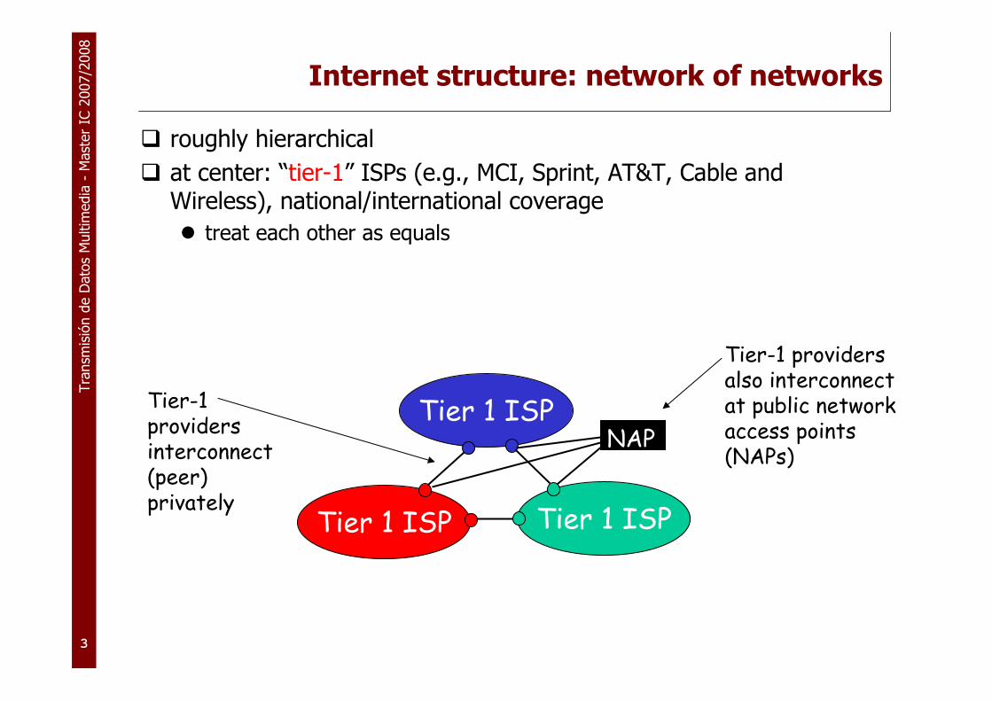
� roughly hierarchical
� at center: “tier-1” ISPs (e.g., MCI, Sprint, AT&T, Cable and Wireless), national/international coverage
� treat each other as equals
Tier 1 ISP
Tier 1 ISP
Tier 1 ISP
Tier-1 providers interconnect (peer) privately
NAP
Tier-1 providers also interconnect at public network access points (NAPs)

Tra
nsm
isió
n d
e D
ato
s M
ultim
edia
-M
ast
er
IC 2
007/2
008
4
Tier-1 ISP: e.g., Sprint
Sprint US backbone network
Seattle
Atlanta
Chicago
Roachdale
Stockton
San Jose
Anaheim
Fort Worth
Orlando
Kansas City
CheyenneNew York
PennsaukenRelayWash. DC
Tacoma
DS3 (45 Mbps)
OC3 (155 Mbps)
OC12 (622 Mbps)
OC48 (2.4 Gbps)

Tra
nsm
isió
n d
e D
ato
s M
ultim
edia
-M
ast
er
IC 2
007/2
008
5
Internet structure: network of networks
� “Tier-2” ISPs: smaller (often regional) ISPs
� Connect to one or more tier-1 ISPs, possibly other tier-2 ISPs
Tier 1 ISP
Tier 1 ISP
Tier 1 ISP
NAP
Tier-2 ISPTier-2 ISP
Tier-2 ISP Tier-2 ISP
Tier-2 ISP
Tier-2 ISP pays tier-1 ISP for connectivity to rest of Internet� tier-2 ISP is customer oftier-1 provider
Tier-2 ISPs also peer privately with each other, interconnect at NAP

Tra
nsm
isió
n d
e D
ato
s M
ultim
edia
-M
ast
er
IC 2
007/2
008
6
Internet structure: network of networks
� “Tier-3” ISPs and local ISPs
� last hop (“access”) network (closest to end systems)
Tier 1 ISP
Tier 1 ISP
Tier 1 ISP
NAP
Tier-2 ISPTier-2 ISP
Tier-2 ISP Tier-2 ISP
Tier-2 ISP
localISPlocal
ISPlocalISP
localISP
localISP Tier 3
ISP
localISP
localISP
localISP
Local and tier-3 ISPs are customers ofhigher tier ISPsconnecting them to rest of Internet

Tra
nsm
isió
n d
e D
ato
s M
ultim
edia
-M
ast
er
IC 2
007/2
008
7
Internet structure: network of networks
� a packet passes through many networks!
Tier 1 ISP
Tier 1 ISP
Tier 1 ISP
NAP
Tier-2 ISPTier-2 ISP
Tier-2 ISP Tier-2 ISP
Tier-2 ISP
localISPlocal
ISPlocalISP
localISP
localISP Tier 3
ISP
localISP
localISP
localISP

Tra
nsm
isió
n d
e D
ato
s M
ultim
edia
-M
ast
er
IC 2
007/2
008
8
Network Access Points (NAPs)
Source: Boardwatch.com
Note: Peers in this context are commercial backbones..droh

Tra
nsm
isió
n d
e D
ato
s M
ultim
edia
-M
ast
er
IC 2
007/2
008
9Source: www.lightreading.com
MCI/WorldCom/UUNET Global Backbone

Tra
nsm
isió
n d
e D
ato
s M
ultim
edia
-M
ast
er
IC 2
007/2
008
1
0
The situation in Europe
See: http://www.geant2.net/server/show/nav.1368

Tra
nsm
isió
n d
e D
ato
s M
ultim
edia
-M
ast
er
IC 2
007/2
008
1
1
Standards
� Mandatory vs. voluntary
� Allowed to use vs. likely to sell
� Example: health & safety standards �UL listing for electrical appliances, fire codes
� Telecommunications and networking always focus of standardization
� 1865: International Telegraph Union (ITU)
� 1956: International Telephone and Telegraph Consultative Committee (CCITT)
� Five major organizations:
� ITU for lower layers, multimedia collaboration
� IEEE for LAN standards (802.x)
� IETF for network, transport & some applications
� W3C for web-related technology (XML, SOAP)
� ISO for media content (MPEG)

Tra
nsm
isió
n d
e D
ato
s M
ultim
edia
-M
ast
er
IC 2
007/2
008
1
2
Who makes the rules? - ITU
� ITU = ITU-T (telecom standardization) + ITU-R (radio) + development
� http://www.itu.int
� 14 study groups
� produce Recommendations:
� E: overall network operation, telephone service (E.164)
� G: transmission system and media, digital systems and networks (G.711)
� H: audiovisual and multimedia systems (H.323)
� I: integrated services digital network (I.210); includes ATM
� V: data communications over the telephone network (V.24)
� X: Data networks and open system communications
� Y: Global information infrastructure and internet protocol aspects

Tra
nsm
isió
n d
e D
ato
s M
ultim
edia
-M
ast
er
IC 2
007/2
008
1
3
ITU
� Initially, national delegations
� Members: state, sector, associate
� Membership fees (> 10,500 SFr)
� Now, mostly industry groups doing work
� Initially, mostly (international) telephone services
� Now, transition from circuit-switched to packet-switched universe & lower network layers (optical)
� Documents cost SFr, but can get three freebies for each email address

Tra
nsm
isió
n d
e D
ato
s M
ultim
edia
-M
ast
er
IC 2
007/2
008
1
4
IETF
� IETF (Internet Engineering Task Force)
� see RFC 3233 (“Defining the IETF”)
� Formed 1986, but earlier predecessor organizations (1979-)
� RFCs date back to 1969
� Initially, largely research organizations and universities, now mostly R&D labs of equipment vendors and ISPs
� International, but 2/3 United States
� meetings every four months
� about 300 companies participating in meetings
� but Cisco, Ericsson, Lucent, Nokia, etc. send large delegations

Tra
nsm
isió
n d
e D
ato
s M
ultim
edia
-M
ast
er
IC 2
007/2
008
1
5
IETF
� Supposed to be engineering, i.e., translation of well-understood technology � standards
� make choices, ensure interoperability
� reality: often not so well defined
� Most development work gets done in working groups (WGs)
� specific task, then dissolved (but may last 10 years…)
� typically, small clusters of authors, with large peanut gallery
� open mailing list discussion for specific problems
� interim meetings (1-2 days) and IETF meetings (few hours)
� published as Internet Drafts (I-Ds)
� anybody can publish draft-somebody-my-new-protocol
� also official working group documents (draft-ietf-wg-*)
� versioned (e.g., draft-ietf-avt-rtp-10.txt)
� automatically disappear (expire) after 6 months

Tra
nsm
isió
n d
e D
ato
s M
ultim
edia
-M
ast
er
IC 2
007/2
008
1
6
IETF process
� WG develops � WG last call � IETF last call � approval (or not) by IESG � publication as RFC
� IESG (Internet Engineering Steering Group) consists of area directors – they vote on proposals
� areas = applications, general, Internet, operations and management, routing, security, sub-IP, transport
� Also, Internet Architecture Board (IAB)
� provides architectural guidance
� approves new working groups
� process appeals

Tra
nsm
isió
n d
e D
ato
s M
ultim
edia
-M
ast
er
IC 2
007/2
008
1
7
IETF activities
� general (3): ipr, nomcom, problem� applications (25): crisp, geopriv, impp, ldapbis, lemonade, opes,
provreg, simple, tn3270e, usefor, vpim, webdav, xmpp� internet (18) = IPv4, IPv6, DNS, DHCP: dhc, dnsext, ipoib, itrace,
mip4, nemo, pana, zeroconf� oam (22) = SNMP, RADIUS, DIAMETER: aaa, v6ops, netconf, …� routing (13): forces, ospf, ssm, udlr, …� security (18): idwg, ipsec, openpgp, sasl, smime, syslog, tls,
xmldsig, …� subip (5) = “layer 2.5”: ccamp, ipo, mpls, tewg� transport (26): avt (RTP), dccp, enum, ieprep, iptel, megaco,
mmusic (RTSP), nsis, rohc, sip, sipping (SIP), spirits, tsvwg

Tra
nsm
isió
n d
e D
ato
s M
ultim
edia
-M
ast
er
IC 2
007/2
008
1
8
RFCs
� Originally, “Request for Comment”
� now, mostly standards documents that are well settled
� published RFCs never change
� always ASCII (plain text), sometimes PostScript
� anybody can submit RFC, but may be delayed by review (“end run avoidance”)
� see April 1 RFCs (RFC 1149, 3251, 3252)
� accessible at http://www.ietf.org/rfc/ and http://www.rfc-editor.org/
Tra
nsm
isió
n d
e D
ato
s M
ultim
edia
-M
ast
er
IC 2
007/2
008
1
9
IETF process issues
� Can take several years to publish a standard
� see draft-ietf-problem-issue-statement
� Relies on authors and editors to keep moving
� often, busy people with “day jobs” � spurts three times a year
� Lots of opportunities for small groups to delay things
� Original idea of RFC standards-track progression:
� Proposed Standard (PS) = kind of works
� Draft Standard (DS) = solid, interoperability tested (2 interoperable implementations for each feature), but not necessarily widely used
� Standard (S) = well tested, widely deployed

Tra
nsm
isió
n d
e D
ato
s M
ultim
edia
-M
ast
er
IC 2
007/2
008
2
0
IETF process issues
� Reality: very few protocols progress beyond PS
� and some widely-used protocols are only I-Ds
� In addition: Informational, Best Current Practice (BCP), Experimental, Historic
� Early IETF: simple protocols, stand-alone
� TCP, HTTP, DNS, BGP, …
� Now: systems of protocols, with security, management, configuration and scaling
� lots of dependencies � wait for others to do their job

Tra
nsm
isió
n d
e D
ato
s M
ultim
edia
-M
ast
er
IC 2
007/2
008
2
1
Other Internet standards organizations
� ISOC (Internet Society)
� legal umbrella for IETF, development work
� IANA (Internet Assigned Numbers Authority)
� assigns protocol constants
� NANOG (North American Network Operators Group) (http://www.nanog.org)
� operational issues
� holds nice workshop with measurement and “real world” papers
� RIPE, ARIN, APNIC
� regional IP address registries � dole out chunks of address space to ISPs
� routing table management
Tra
nsm
isió
n d
e D
ato
s M
ultim
edia
-M
ast
er
IC 2
007/2
008
2
2
ICANN
� Internet Corporation for Assigned Names and Numbers
� manages IP address space (at top level)
� DNS top-level domains (TLD)
� ccTLD: country codes (.us, .uk, …)
� gTLDs (.com, .edu, .gov, .int, .mil, .net, and .org)
� uTLD (unsponsored): .biz, .info, .name, and .pro
� sTLD (sponsored): .aero, .coop, and .museum
� actual domains handled by registrars

Transmisión de Datos Multimedia – http://www.grc.upv.es/docencia/tdm – Master IC 2007/2008
Tema 1: Tecnologías de red.Tema 1: Tecnologías de red.
�Estructura de Internet
�Redes “core”� SONET
� DWDM
�Redes de acceso� Redes cableadas: Ethernet et al.
� Redes inalámbricas: IEEE 802.11, UMTS et al.

Tra
nsm
isió
n d
e D
ato
s M
ultim
edia
-M
ast
er
IC 2
007/2
008
2
4
IP and Traditional Transport
� In the 80’s, software based routers were interconnected via relatively slow links
� 56K (early 80’s),
� to fractional T1, to full T1,
� to T3
� This was layered over core TDM infrastructure
� Which was intended for voice and circuits
� Generally, data folks ignored TDM folks, and vice versa
Tra
nsm
isió
n d
e D
ato
s M
ultim
edia
-M
ast
er
IC 2
007/2
008
2
5
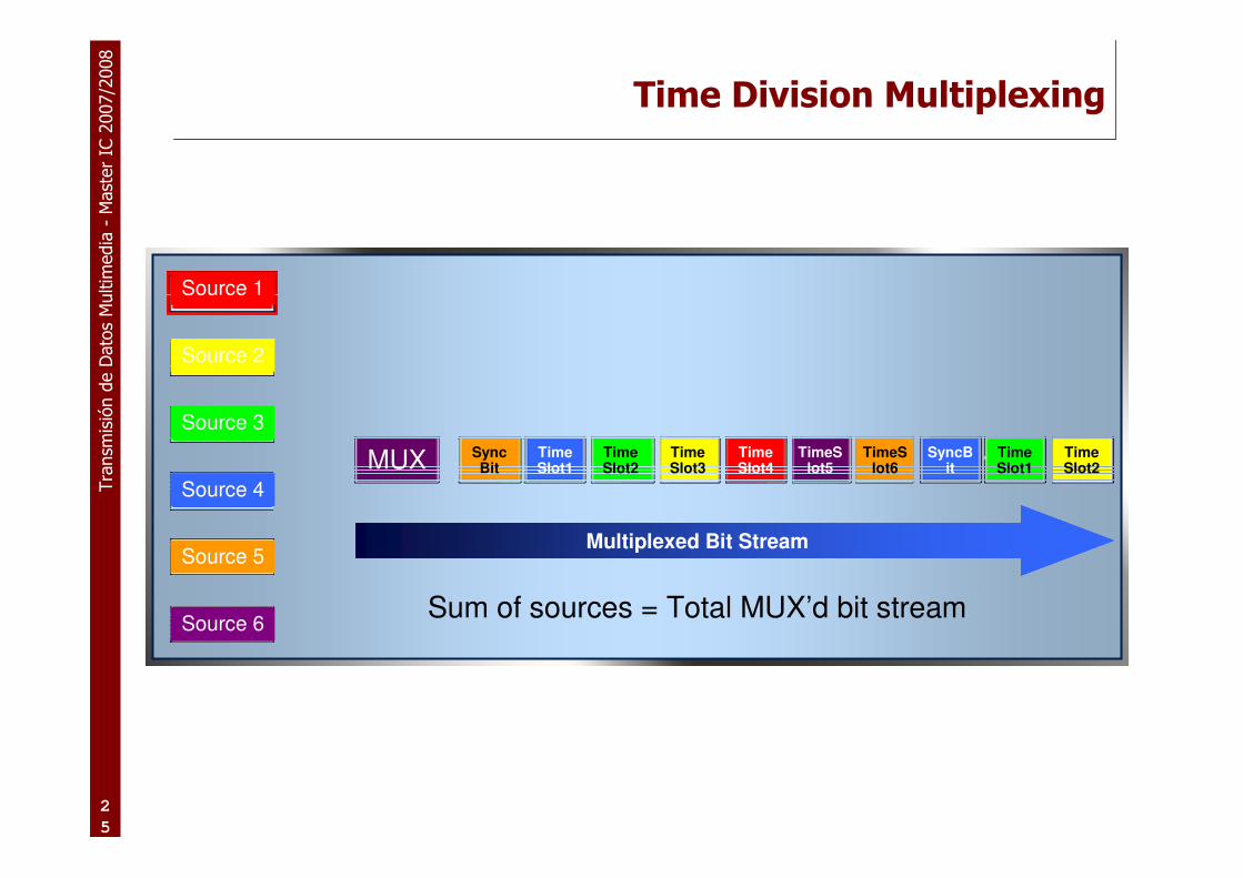
Time Division Multiplexing
Multiplexed Bit Stream
Sum of sources = Total MUX’d bit stream
MUX TimeSlot1
TimeSlot2
TimeSlot4
TimeSlot3
TimeSlot6
TimeSlot1
TimeSlot5
TimeSlot2
SyncBit
SyncBit
Source 1
Source 2
Source 3
Source 4
Source 5
Source 6

Tra
nsm
isió
n d
e D
ato
s M
ultim
edia
-M
ast
er
IC 2
007/2
008
2
6
SONET & SDH
� SONET - Synchronous Optical NETwork
� ANSI/Bellcore standard
� SDH - Synchronous Digital Hierarchy
� ITU (European) standard
� Both standards are practically identical
� Standards for a synchronous digital transmission system of TDM traffic over fiber networks.
� Standards based system for data rates above a T3.

Tra
nsm
isió
n d
e D
ato
s M
ultim
edia
-M
ast
er
IC 2
007/2
008
2
7
SONET/SDH Hierarchy
� STS - Synchronous Transport Signals
� 51.84Mbps - base level of SONET hierarchy
� STM - Synchronous Transport Module
� 155.52Mbps - base level of SDH hierarchy
� Exactly equal to STS-3
STS OC STM
Bit Rate
(Mbps)STS-1 OC-1 51.84
STS-3 OC-3 STM-1 155.52
STS-12 OC-12 STM-4 622.08
STS-48 OC-48 STM-16 2488.32
STS-192 OC-192 STM-64 9953.28
STS-768 OC-768 STM-256 39813.12

Tra
nsm
isió
n d
e D
ato
s M
ultim
edia
-M
ast
er
IC 2
007/2
008
2
8
STS/OC/STM
� STS-n and OC-n are identical -
� OC-n names are used for optical interconnects
� STS-n names are used for electrical interconnects
� OC-n is exactly n times the rate of an OC-1 signal.
� STM-1 signal is exactly 3 times the rate of an STS-1 signal
� STM-n is exactly n times the rate of an STM-1 signal
Tra
nsm
isió
n d
e D
ato
s M
ultim
edia
-M
ast
er
IC 2
007/2
008
2
9
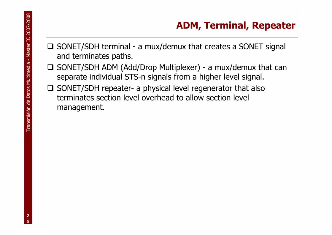
ADM, Terminal, Repeater
� SONET/SDH terminal - a mux/demux that creates a SONET signal and terminates paths.
� SONET/SDH ADM (Add/Drop Multiplexer) - a mux/demux that can separate individual STS-n signals from a higher level signal.
� SONET/SDH repeater- a physical level regenerator that also terminates section level overhead to allow section level management.
Tra
nsm
isió
n d
e D
ato
s M
ultim
edia
-M
ast
er
IC 2
007/2
008
3
0
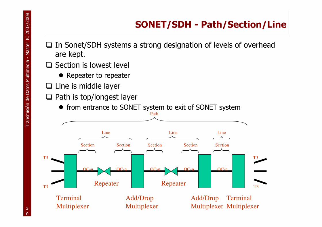
SONET/SDH - Path/Section/Line
� In Sonet/SDH systems a strong designation of levels of overhead are kept.
� Section is lowest level
� Repeater to repeater
� Line is middle layer
� Path is top/longest layer
� from entrance to SONET system to exit of SONET system
Repeater
Add/Drop
Multiplexer
Add/Drop
Multiplexer
Terminal
Multiplexer
Terminal
Multiplexer
Repeater
Section Section Section Section Section
Line Line Line
Path
T3
T3
T3
T3
OC-n OC-n OC-n OC-n OC-n

Tra
nsm
isió
n d
e D
ato
s M
ultim
edia
-M
ast
er
IC 2
007/2
008
3
1
SONET/SDH - Section & Line Overhead
� The section overhead is the first 3 rows of the first 3 columns (9 bytes) per frame.
� The line overhead is the lower 6 rows of the first 3 columns (18bytes) per frame.
� An STS-1 frame consists of 810 bytes (octets) sent in 125µs.
� 810 * 8 * 8000 = 51.84Mbps
� The 810 bytes are arranged as 90 columns x 9 rows
� 3 columns are overhead
� 87 columns are actual data
STS-1 Payload
87 columnsA1 A2 C1
B1 E1 F1
D1 D2 D3
H1 H2 H3
B2 K1 K2
D4 D5 D6
D7 D8 D9
D10 D11 D12
Z1 Z2 Z3
Section
Overhead
Line
Overhead
Tra
nsm
isió
n d
e D
ato
s M
ultim
edia
-M
ast
er
IC 2
007/2
008
3
2
STS concatenated signals
� Multiple STS-1s can be grouped together into a single higher bit rate facility.
� Extra overhead bytes are ignored.
� Technically, any number of STS-1s can be grouped, but the only groupings normally supported are:
� STS-3C, STS-12C, STS-48C
� Generally a grouping must fall on a boundary of the same size inside of the OC-n carrier
� A STS-3C must fall on a boundary of 3
� STS-12C must fall on a boundary of 12
� Typically used for situations where ATM or Packets are sent over a SONET network.

Tra
nsm
isió
n d
e D
ato
s M
ultim
edia
-M
ast
er
IC 2
007/2
008
3
3
Traditional View of Routers and Links

Tra
nsm
isió
n d
e D
ato
s M
ultim
edia
-M
ast
er
IC 2
007/2
008
3
4
Terminal Multiplexer
SONET/SDHADM
SONET/SDHADM
SONET/SDHADM
SONET/SDHADM
SONET/SDHDCS
SONET/SDHDCS
SONET/SDHDCS
Terminal Multiplexer
Terminal Multiplexer
Terminal Multiplexer
Terminal Multiplexer Terminal
Multiplexer
SONET/SDHADM
SONET/SDHADM
Reality has always been more complex

Tra
nsm
isió
n d
e D
ato
s M
ultim
edia
-M
ast
er
IC 2
007/2
008
3
5
Optical Fiber Evolution
� Fiber is better than copper wire
� Purity – low attenuation and distortion
� Longer distances, lower bit error rates
� Higher frequency signals – massive bandwidth
� Different wavelengths – massive bandwidth
� Immunity to noise
� Security – difficult to tap
� Small size and weight
� Easier installation
� Bundles of fibers in same space as copper wire
� Multimode fiber� Low cost – LEDs, not lasers
� Many wavelengths (modes)
� Dispersion – limits bandwidth and distance� Light pulses spread out
� Intramodal – different delay per mode
� Typically 2 km maximum distance
� Large diameter cores – for multiple modes� Initially flat profile
� Stepped end improves performance
� Single-mode fiber� One wavelength – small core
� Less interference and loss� Greater distance (up to 100 km)
� More expensive components – lasers
� Minimized dispersion point at 1310 nm� Not suitable for EDFA (Erbium Doped Fiber-optic
Amplifier)
� Non-zero dispersion shifted fiber� Optimized for longer distances
� Optimized for higher bandwidth
� Minimized dispersion point shifted to 1550 nm� Suitable for Erbium-based optical amplifiers
� Silica-based fibers have lowest attenuation at 1550 nm, not 1310

Tra
nsm
isió
n d
e D
ato
s M
ultim
edia
-M
ast
er
IC 2
007/2
008
3
6
SONET/SDH ADM SONET/SDH ADM
WDM Node WDM Node
From One Wavelength Per
Fiber to Many
ADM
Single Fiber
SONET/SDH ADM
Single Fiber
Wave Division Multiplexing
OT = Optical Transponder
OT
ADM
ADM
ADM
ADM
ADM
ADM
ADM
OT

Tra
nsm
isió
n d
e D
ato
s M
ultim
edia
-M
ast
er
IC 2
007/2
008
3
7
WDM System Elements
SONET/SDH ADM
SONET/SDH ADM
SONET/SDH ADM
SONET/SDH ADM
SONET/SDH ADM
SONET/SDH ADM
= Regenerators

Tra
nsm
isió
n d
e D
ato
s M
ultim
edia
-M
ast
er
IC 2
007/2
008
3
8
TDM and WDM Relationship
λλλλ1 … λλλλn
TDM generates output from sum of inputs into a single
bit stream
Laser Output
λλλλλλλλnn
λλλλ1
WDM changes TDM bit stream into wavelengths between 1532 nm and
1560 nm
OT

Tra
nsm
isió
n d
e D
ato
s M
ultim
edia
-M
ast
er
IC 2
007/2
008
3
9
EDFA = Erbium Doped Fiber-optic Amplifier
Dense and Ultra Dense WDM
λλλλ8
WDM 8 Lambdas
2.5 Gbps per lambda
λλλλ1 λλλλ1
λλλλ8
EDFA = Erbium Doped Fiber-optic Amplifier
λλλλ2 λλλλ2

Tra
nsm
isió
n d
e D
ato
s M
ultim
edia
-M
ast
er
IC 2
007/2
008
4
0
Dense and Ultra Dense WDM
λλλλ1
λλλλ39
λλλλ1
DWDM 40 Lambdas
λλλλ40
10 Gbps per lambda
λλλλ2 λλλλ2
λλλλ39
λλλλ40EDFA = Erbium Doped Fiber-optic Amplifier
Tra
nsm
isió
n d
e D
ato
s M
ultim
edia
-M
ast
er
IC 2
007/2
008
4
1
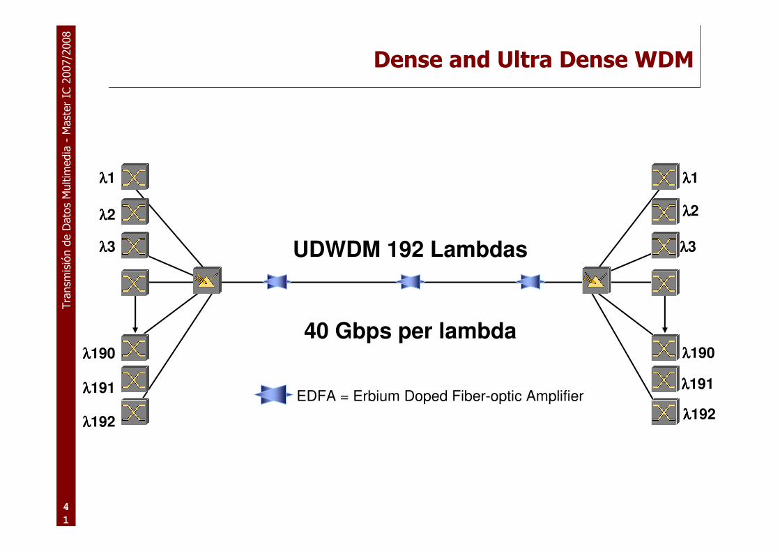
λλλλ190
UDWDM 192 Lambdas
λλλλ191
40 Gbps per lambda
λλλλ3
λλλλ192
λλλλ3
λλλλ190
λλλλ191
λλλλ192
Dense and Ultra Dense WDM
EDFA = Erbium Doped Fiber-optic Amplifier
λλλλ1 λλλλ1
λλλλ2 λλλλ2

Transmisión de Datos Multimedia – http://www.grc.upv.es/docencia/tdm – Master IC 2007/2008
Tema 1: Tecnologías de red.Tema 1: Tecnologías de red.
�Estructura de Internet
�Redes “core”� SONET
� DWDM
�Redes de acceso� Redes cableadas: Ethernet et al.
� Redes inalámbricas: IEEE 802.11, UMTS et al.

Tra
nsm
isió
n d
e D
ato
s M
ultim
edia
-M
ast
er
IC 2
007/2
008
4
3
Los estándares 802.3 de IEEE
Múltiples spanning trees 802.1s
Cambios y mejoras en el spanning tree 802.1w
Bridging en 802.1D
10 Gbase-T (en draft)802.3an
Ethernet in First Mile 2004802.3ah
PoE (Power over Ethernet). Hasta 15W2003802.3af
10 GE 2002802.3ae
link aggregation 2000802.3ad
Extensiones de trama (hasta 1522 bytes) para VLANs1998802.3ac
1000Base-T (GE sobre par trenzado)1999802.3ab
1000Base-X (Gigabit Ethernet)1998802.3z
operación full duplex 1997802.3x e 802.3y
100Mbps Ethernet 1995802.3u
10Base-F Ethernet sobre fibra1993802.3j
10Base-T Ethernet sobre par trenzado de cobre1990802.3i
FOIRL (enlace de fibra)1987802.3d
Especificaciones de repetidores1986802.3c
Original 802.3: 10BASE-5 10BASE-2 10BROAD-361985802.3a
descripciónañosuplemento

Tra
nsm
isió
n d
e D
ato
s M
ultim
edia
-M
ast
er
IC 2
007/2
008
4
4
IEEE 802 standard

Tra
nsm
isió
n d
e D
ato
s M
ultim
edia
-M
ast
er
IC 2
007/2
008
4
5
Estándares de ethernet sobre optico
� ITU-T G.7041 Generic Framing Procedure (GFP)
� ITU-T X.86 Link Access Protocol (LAPS)
� ITU-T H.707 Virtual Concatenation (VCAT)
� ITU-T G.7042 Link Capacity Adjustment Scheme (LCAS)
� Otros:
� IEEE 802.1X Port Based Network Access Control
� IEEE 802.1D Ethernet switching
� IEEE 802.1Q Virtual LAN (VLAN)
� IEEE 802.1P Priorización de tráfico a nivel 2
� IETF: MPLS Multi-Protocol Label Switching
� IEEE 802.17 Resilient Packet Ring (RPR)
� Ver:� http://grouper.ieee.org/groups/802/3/
� http://grouper.ieee.org/groups/802/1/

Tra
nsm
isió
n d
e D
ato
s M
ultim
edia
-M
ast
er
IC 2
007/2
008
4
6
Trama ethernet
� Los datos trasmitidos se encapsulan en un contenedor, que se llama trama
� Este formato de trama DEFINE Ethernet
� Históricamente, existen dos tipos de tramas:
� »802.3 Framing usa en campo de longitud de trama (Length) despues del campo de Source Address
� »Ethernet II (DIX) Framing usa(ba) el campo de tipo de trama (type) despues del campo Source Address
� Ambos tipos de tramas están definidos y soportados dentro de IEEE 802.3

Tra
nsm
isió
n d
e D
ato
s M
ultim
edia
-M
ast
er
IC 2
007/2
008
4
7
Trama ethernet
� El tamaño de trama varía desde 64 a 1518 Bytes, excepto cuando se usa el identificador (tag) de VLAN

Tra
nsm
isió
n d
e D
ato
s M
ultim
edia
-M
ast
er
IC 2
007/2
008
4
8
802.1Q/P
� User Priority- Defines user priority, giving eight (2^3) priority levels. IEEE 802.1P defines theoperation for these 3 user priority bits.
� CFI- Canonical Format Indicator is always set to zero for Ethernet switches. CFI is used forcompatibility reason between Ethernet type network and Token Ring type network. If a framereceived at an Ethernet port has a CFI set to 1, then that frame should not be forwarded as it isto an untagged port.
� VID- VLAN ID is the identification of the VLAN, which is basically used by the standard 802.1Q. It has 12 bits and allow the identification of 4096 (2^12) VLANs. Of the 4096 possible VIDs, a VID of 0 is used to identify priority frames and value 4095 (FFF) is reserved, so the maximumpossible VLAN configurations are 4,094.
� Length/Type- 2 bytes. This field indicates either the number of MAC-client data bytes that are contained in the data field of the frame, or the frame type ID if the frame is assembled using anoptional format.
� Data- Is a sequence of nbytes (48=< n =<1500) of any value. The total frame minimum is64bytes.
� Frame check sequence (FCS)- 4 bytes. This sequence contains a 32-bit cyclic redundancycheck (CRC) value, which is created by the sending MAC and is recalculated by the receiving MAC to check for damaged frames.
User Priority CFI Bits of VLAN ID (VIDI) to identify possible VLANs
3 1 12

Tra
nsm
isió
n d
e D
ato
s M
ultim
edia
-M
ast
er
IC 2
007/2
008
4
9
Servicios Metropolitanos
� Algunos servicios son:
� Conectividad Internet
� Transparent LAN service (punto a punto LAN to LAN)
� L2VPN (punto a punto o multipunto a multipunto LAN to LAN)
� Extranet
� LAN a Frame Relay/ATM VPN
� Conectividad a centro de backup
� Storage area networks (SANs)
� Metro transport (backhaul)
� VoIP
� Algunos se están ofreciendo desde hace años. La diferencia está en que ahora se ofrecen usando conectividad Ethernet !!

Tra
nsm
isió
n d
e D
ato
s M
ultim
edia
-M
ast
er
IC 2
007/2
008
5
0
Evolución de Ethernet
Optical EthernetEoMPLS
VPLSEoRPR
NG-SONET(EoS)Metro DWDM
Optical EthernetEoMPLS
VPLSRPR
NG-SONET(EoS)Metro DWDM
IP ADSLIP VDSLEPONEFM
Optical EthernetEoRPR
NG-SONET(EoS)
Acceso Distribución Metro Metro Core
GlobalInternet
ATMSONET/SDH
ATMSONET/SDH
ATM ADSLT1/E1
FRATM
GlobalInternet
Casa
MDU
STU
MTU
Resid
en
cia
lE
mp
resa
Tra
nsm
isió
n d
e D
ato
s M
ultim
edia
-M
ast
er
IC 2
007/2
008
5
1
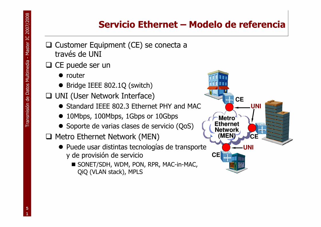
Servicio Ethernet – Modelo de referencia
� Customer Equipment (CE) se conecta a través de UNI
� CE puede ser un
� router
� Bridge IEEE 802.1Q (switch)
� UNI (User Network Interface)
� Standard IEEE 802.3 Ethernet PHY and MAC
� 10Mbps, 100Mbps, 1Gbps or 10Gbps
� Soporte de varias clases de servicio (QoS)
� Metro Ethernet Network (MEN)
� Puede usar distintas tecnologías de transportey de provisión de servicio
� SONET/SDH, WDM, PON, RPR, MAC-in-MAC, QiQ (VLAN stack), MPLS
CE
CE
CE
UNI
Metro Metro Ethernet Ethernet Network Network (MEN)(MEN)
UNI

Tra
nsm
isió
n d
e D
ato
s M
ultim
edia
-M
ast
er
IC 2
007/2
008
5
2
Servicio Ethernet – Modelo (2)
� Sobre el anterior modelo, se añade un cuarto ingrediente: una Ethernet Virtual Connection (EVC)
� EVC: es una asociación entre dos o más UNI
� Es creada por el proveedor del servicio para un cliente
� Una trama enviada en un EVC puede ser enviada a uno o más UNIs del EVC:
� Nunca será enviada de vuelta al UNI de entrada.
� Nunca será enviada a un UNI que no pertenezca al EVC.
� Las EVC´s pueden ser:
� Punto a punto (E-Line)
� Multipunto a multipunto (E-LAN)
� Cada tipo de servicio ethernet tiene un conjunto de atributos de servicio y sus correspondientes parámetros que definen las capacidades del servicio.

Tra
nsm
isió
n d
e D
ato
s M
ultim
edia
-M
ast
er
IC 2
007/2
008
5
3
Atributos de un servicio en particular Ethernet
� Multiplexación de servicios
� Asocia una UNI con varias EVC. Puede ser:
� Hay varios clientes en una sóla puerta (ej. En un POP UNI)
� Hay varias conexiones de servicios distintos para un solo cliente
� Transparencia de VLAN
� Significa que proveedor del servico no cambia el identificador de la VLAN ( el MEN aparece como un gran switch)
� En el servicio de acceso a Internet tiene poco importancia
� “Bundling”
� Más de una VLAN de cliente está asociada al EVC en una UNI
� Etc.
Tra
nsm
isió
n d
e D
ato
s M
ultim
edia
-M
ast
er
IC 2
007/2
008
5
4
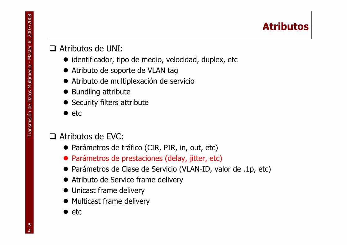
Atributos
� Atributos de UNI:
� identificador, tipo de medio, velocidad, duplex, etc
� Atributo de soporte de VLAN tag
� Atributo de multiplexación de servicio
� Bundling attribute
� Security filters attribute
� etc
� Atributos de EVC:
� Parámetros de tráfico (CIR, PIR, in, out, etc)
� Parámetros de prestaciones (delay, jitter, etc)
� Parámetros de Clase de Servicio (VLAN-ID, valor de .1p, etc)
� Atributo de Service frame delivery
� Unicast frame delivery
� Multicast frame delivery
� etc

Tra
nsm
isió
n d
e D
ato
s M
ultim
edia
-M
ast
er
IC 2
007/2
008
5
5
Servicio Ethernet Line (E-Line)
Data
UNI
CE
CE
CE
Point-to-Point Ethernet Virtual Circuits
(EVC)
Metro Ethernet Network
1 or more UNIs
UNI
Video
IP PBX
Servers
Data
IP Voice
IP Voice

Tra
nsm
isió
n d
e D
ato
s M
ultim
edia
-M
ast
er
IC 2
007/2
008
5
6
Servicio Ethernet Line (E-Line)
� Una E-Line puede operar con ancho de banda dedicado ó con un ancho de banda compartido.
� EPL: Ethernet Private Line� Es un servicio EVC punto a punto con un ancho de banda dedicado
� El cliente siempre dispone del CIR
� Normalmente en canales SDH (en NGN) ó en redes MPLS
� Es como una línea en TDM, pero con una interfaz ethernet
� EVPL:Ethernet Virtual Private Line� En este caso hay un CIR y un EIR y una métrica para el soporte de
SLA´s
� Es similar al FR
� Se suele implementar con canales TDM compartidos ó con redes de conmutación de paquetes usando SW´s y/o routers

Tra
nsm
isió
n d
e D
ato
s M
ultim
edia
-M
ast
er
IC 2
007/2
008
5
7
Servicio Ethernet LAN (E-LAN)
CE
CE
CE
Metro Ethernet Network
CE
Multipoint-to-Multipoint Ethernet Virtual Circuit
(EVC)
UNI
UNI
UNI
UNI
IP PBX
Servers
Data
Data
Data
IP Voice
IP Voice
IP Voice

Tra
nsm
isió
n d
e D
ato
s M
ultim
edia
-M
ast
er
IC 2
007/2
008
5
8
Servicio Ethernet LAN (E-LAN)
� Una E-LAN puede operar con ancho de banda dedicado ó con un ancho de banda compartido.
� EPLan: Ethernet Private LAN
� Suministra una conectividad multipunto entre dos o más UNI´s, con un ancho de banda dedicado.
� EVPLan: Ethernet Virtual Private LAN
� Otros nombres:
� VPLS: Virtual Private Lan Service
� TLS: Transparent Lan Service
� VPSN: Virtual Private Switched Network
� La separación de clientes vía encapsulación: las etiquetas de VLAN´sdel proveedor no son suficientes (4096)
� Es el servicio más rentable desde el punto de vista del proveedor.

Tra
nsm
isió
n d
e D
ato
s M
ultim
edia
-M
ast
er
IC 2
007/2
008
5
9
Metro tecnologías...
� Los servicios Metro Ethernet services no necesitan que toda la red de nivel 2 sea ethernet; tambien puede ser:
� Ethernet over SONET/SDH (EOS)
� Resilient Packet Ring (RPR)
� Ethernet Transport
� Ethernet sobre MPLS

Tra
nsm
isió
n d
e D
ato
s M
ultim
edia
-M
ast
er
IC 2
007/2
008
6
0
Implementaciones de los EVC (Ethernet Virtual Conn.)
� Virtual Private LAN Services(VPLS)
� Es un tipo de VPN de nivel 2
� La red del proveedor emula la función de un conmutador de LAN ó bridge, para conectar todos los UNI del cliente, para formar una única VLAN
� Los requerimientos en el CE son distintos a los de antes
� Cada PE debe actuar como un bridge de ethernet
� Se puede implementar poniendo ethernet en MPLS óbien, haciendo stack de VLAN usando Q-in-Q
� Ver http://vpls.org

Transmisión de Datos Multimedia – http://www.grc.upv.es/docencia/tdm – Master IC 2007/2008
Tema 1: Tecnologías de red.Tema 1: Tecnologías de red.
�Estructura de Internet
�Redes “core”� SONET
� DWDM
�Redes de acceso� Redes cableadas: Ethernet et al.
� Redes inalámbricas: IEEE 802.11, UMTS et al.

Tra
nsm
isió
n d
e D
ato
s M
ultim
edia
-M
ast
er
IC 2
007/2
008
6
2
Taxonomy
WirelessNetworking
Multi-hop
Infrastructure-less(ad-hoc)
Infrastructure-based(Hybrid)
Infrastructure-less(MANET)
SingleHop
CellularNetworks Wireless Sensor
NetworksWireless Mesh
Networks
Car-to-car Networks(VANETs)
Infrastructure-based(hub&spoke)
802.11 802.16 Bluetooth802.11
Tra
nsm
isió
n d
e D
ato
s M
ultim
edia
-M
ast
er
IC 2
007/2
008
6
3
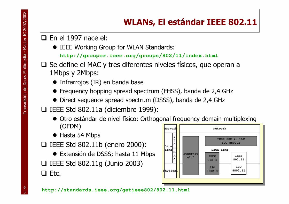
WLANs, El estándar IEEE 802.11
� En el 1997 nace el:
� IEEE Working Group for WLAN Standards:http://grouper.ieee.org/groups/802/11/index.html
� Se define el MAC y tres diferentes niveles físicos, que operan a 1Mbps y 2Mbps:
� Infrarrojos (IR) en banda base
� Frequency hopping spread spectrum (FHSS), banda de 2,4 GHz
� Direct sequence spread spectrum (DSSS), banda de 2,4 GHz
� IEEE Std 802.11a (diciembre 1999):
� Otro estándar de nivel físico: Orthogonal frequency domain multiplexing(OFDM)
� Hasta 54 Mbps
� IEEE Std 802.11b (enero 2000):
� Extensión de DSSS; hasta 11 Mbps
� IEEE Std 802.11g (Junio 2003)
� Etc.
Data Link
Network
IEEE 802.2. LLC
ISO 8802.2
IEEE
802.3
ISO
8802.3
Network
Data
Link
Physical
L
L
C
M
A
C
Ethernet
v2.0IEEE
802.11
ISO
8802.11
http://standards.ieee.org/getieee802/802.11.html

Tra
nsm
isió
n d
e D
ato
s M
ultim
edia
-M
ast
er
IC 2
007/2
008
6
4
Arquitectura 802.11
infrastructure Basic Service Set (BSS)Componentes:
�Estación (STA)
�Access Point (AP)
�Basic Service Set (BSS)
�Extended Service Set (ESS)
Independent Basic Service Set (IBSS)�Estructura descentralizada
�Flexible:
�Redes pequeñas y grandes,
�Redes transitorias y permanentes
�Control del consumo de potencia

Tra
nsm
isió
n d
e D
ato
s M
ultim
edia
-M
ast
er
IC 2
007/2
008
6
5
El MAC: entrega de datos fiable
� CSMA/CA con binaryexponential backoff
� El protocolo mínimo consiste de dos tramas: DATOS+ACK
� El standard propone RTS-CTS-DATOS-ACK
PointCoordinationFunction (PCF)
Distributed CoordinationFunction (DCF)
MAC
Servicios sin contienda Servicios con contienda
DIFS DIFS
PIFS
SIFS
ventana de contienda
defer access
busy medium
slo
t
Los 5 valores de timing:• Slot time• SIFS: short interframe space• PIFS: PCF interframe space (=SIFS+1slot)• DIFS: DCF interframe space (=SIFS+2slots)• EIFS: extended interframe space
Los 5 valores de timing:• Slot time• SIFS: short interframe space• PIFS: PCF interframe space (=SIFS+1slot)• DIFS: DCF interframe space (=SIFS+2slots)• EIFS: extended interframe space

Tra
nsm
isió
n d
e D
ato
s M
ultim
edia
-M
ast
er
IC 2
007/2
008
6
6
Mecanismo de detección de portadora
� Se basa en el network allocation vector (NAV)
RTS
DIFS
CTS
SIFS
data
ACK
SIFS SIFS
DIFS
NAV (RTS)
NAV (CTS)
fuente
destino
otro STA
defer access
ventana de contienda

Tra
nsm
isió
n d
e D
ato
s M
ultim
edia
-M
ast
er
IC 2
007/2
008
6
7
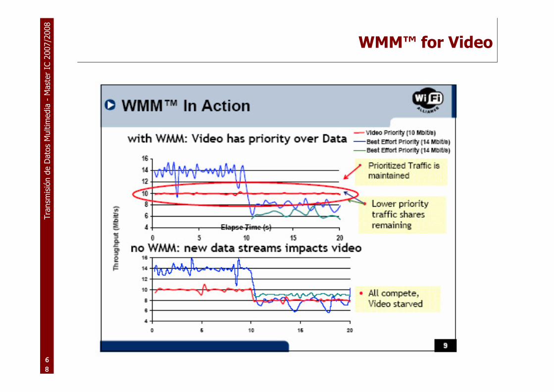
QoS: 802.11e and WMM™
� QoS needed for audio, voice, video
� Original Wi-Fi® didn’t have QoS
� IEEE 802.11e is new QoS standard
� Still in process after more than 4 years
� Both “prioritized” and “guaranteed” QoS
� WMM (Wi-Fi Multimedia)
� Prioritized QoS subset of 802.11e draft
� Widely accepted by 802.11e members
� Added to Wi-Fi certification in September 2004
� Already included in some products
Tra
nsm
isió
n d
e D
ato
s M
ultim
edia
-M
ast
er
IC 2
007/2
008
6
8
WMM™ for Video
Source: Wi-Fi Alliance

Tra
nsm
isió
n d
e D
ato
s M
ultim
edia
-M
ast
er
IC 2
007/2
008
6
9
Bluetooth Specifications
� Bluetooth is a system solution comprising hardware, software andinteroperability requirements. The Bluetooth specifications specify the complete system.
� De facto standard - open specifications.� Two part document - Volume 1:Core and Volume 2:Profiles.� Bluetooth specs developed by Bluetooth SIG.
� February 1998: The Bluetooth SIG is formed� promoter company group: Ericsson, IBM, Intel, Nokia, Toshiba
� May 1998: The Bluetooth SIG goes “public”� July 1999: 1.0A spec (>1,500 pages) is published� December 1999: ver. 1.0B is released� December 1999: The promoter group increases to 9
�3Com, Lucent, Microsoft, Motorola
� February 2000: There are 1,500+ adopters
� 0.7 ---> 0.9 ---> 1.0A ---> 1.0B ---> 1.1 --> � November 2003: release 1.2� Currently (November 2004), release 2.0
� (aka EDR or Extended Data Rate) triples the data rate up to about 2 Mb/s

Tra
nsm
isió
n d
e D
ato
s M
ultim
edia
-M
ast
er
IC 2
007/2
008
7
0
release 2.0: the new partitioning

Tra
nsm
isió
n d
e D
ato
s M
ultim
edia
-M
ast
er
IC 2
007/2
008
7
1
Bluetooth usage
� Low-cost, low-power, short range radio � a cable replacement technology� Common (File transfer, synchronisation, internet bridge, conference
table)
� Hidden computing (background synchronisation, audio/video player)
� Future (PC login, remote control)
� Why not use Wireless LANs?� power
� cost

Tra
nsm
isió
n d
e D
ato
s M
ultim
edia
-M
ast
er
IC 2
007/2
008
7
2
Bluetooth RF
� 1 Mb/s symbol rate� Normal range 10m (0dBm)� Optional range 100m (+20dBm)� Normal transmission power 0dBm (1mW)� Optional transmission power -30 to +20dBm (100mW)� Receiver sensitivity -70dBm� Frequency band 2.4Ghz ISM band� Gross data rate 1Mbit/s� Max data transfer 721+56kbps/3 voice channels� Power consumption 30uA(max), 300uA(standby), ~50uA(hold/park)� Packet switching protocol based on frequency hop scheme with
1600 hops/s

Tra
nsm
isió
n d
e D
ato
s M
ultim
edia
-M
ast
er
IC 2
007/2
008
7
3
Bluetooth Power Class Table
30m10m0dBm1mWClass 3
50m16m4dBm2.5mWClass 2
300m42m20dBm100mWClass 1
Range inFree Space
Expected RangeMax Output PowerMax Output PowerPower Class
Tra
nsm
isió
n d
e D
ato
s M
ultim
edia
-M
ast
er
IC 2
007/2
008
7
4
Bluetooth Network Topology
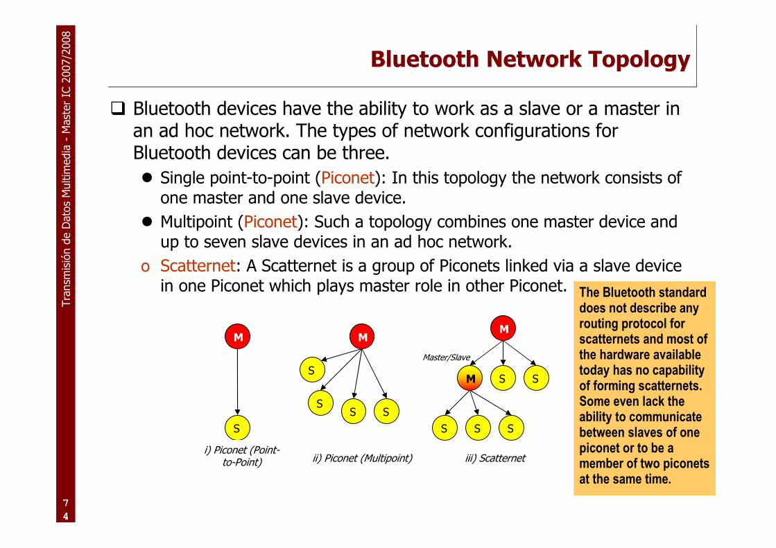
� Bluetooth devices have the ability to work as a slave or a master in an ad hoc network. The types of network configurations for Bluetooth devices can be three.
� Single point-to-point (Piconet): In this topology the network consists of one master and one slave device.
� Multipoint (Piconet): Such a topology combines one master device and up to seven slave devices in an ad hoc network.
o Scatternet: A Scatternet is a group of Piconets linked via a slave device in one Piconet which plays master role in other Piconet.
M
S
i) Piconet (Point-to-Point)
M
SS
S
S
ii) Piconet (Multipoint)
M
S S S
M
S S
Master/Slave
iii) Scatternet
The Bluetooth standard does not describe any routing protocol for scatternets and most of the hardware available today has no capability of forming scatternets. Some even lack the ability to communicate between slaves of one piconet or to be a member of two piconets at the same time.

Tra
nsm
isió
n d
e D
ato
s M
ultim
edia
-M
ast
er
IC 2
007/2
008
7
5
Bluetooth stack: short version
RF
Baseband
Link Manager
L2CAP
SDPRFCOMM
Applications
HCI

Tra
nsm
isió
n d
e D
ato
s M
ultim
edia
-M
ast
er
IC 2
007/2
008
7
6
Transport Protocol Group (contd.)
� Radio Frequency (RF)
� Sending and receiving modulated bit streams
� Baseband
� Defines the timing, framing
� Flow control on the link.� Link Manager
� Managing the connection states.
� Enforcing Fairness among slaves.
� Power Management � Logical Link Control & Adaptation Protocol
� Handles multiplexing of higher level protocols
� Segmentation & reassembly of large packets
� Device discovery & QoS
� The Radio, Baseband and Link Manager are on firmware.
� The higher layers could be in software.
� The interface is then through the Host Controller (firmware and driver).
� The HCI interfaces defined for Bluetooth are UART, RS232 and USB.
Source: Farinaz Edalat, Ganesh Gopal, Saswat Misra, Deepti Rao
BLUETOOTH SPECIFICATION, Core Version 1.1 page 543

Tra
nsm
isió
n d
e D
ato
s M
ultim
edia
-M
ast
er
IC 2
007/2
008
7
7
Physical Link Definition
� Synchronous Connection-Oriented (SCO) Link� circuit switching
� symmetric, synchronous services
� slot reservation at fixed intervals
� Asynchronous Connection-Less (ACL) Link� packet switching
� (a)symmetric,
� asynchronous services
� polling access scheme

Tra
nsm
isió
n d
e D
ato
s M
ultim
edia
-M
ast
er
IC 2
007/2
008
7
8
Packet type Name Symmetric (kbps)
Asymmetric (kbps)
1 slot + FEC DM1 108.8 108.8 108.8
1 slot DH1 172.8 172.8 172.8
3 slot + FEC DM3 256.0 384.0 54.4
3 slot DH3 384.0 576.0 86.4
5 slot + FEC DM5 286.7 477.8 36.3
5 slot DH5 432.6 721.0 57.6
ACL data rates

Tra
nsm
isió
n d
e D
ato
s M
ultim
edia
-M
ast
er
IC 2
007/2
008
7
9
Single slot
Three slot
Five slot
fn fn+1 fn+2 fn+3 fn+4 fn+5
Multi-slot packets

Tra
nsm
isió
n d
e D
ato
s M
ultim
edia
-M
ast
er
IC 2
007/2
008
8
0
fn fn+1 fn+2 fn+3 fn+4 fn+5 fn+6 fn+7 fn+8 fn+9 fn+10 fn+11 fn+12
Master
Slave
Symmetric single slot

Tra
nsm
isió
n d
e D
ato
s M
ultim
edia
-M
ast
er
IC 2
007/2
008
8
1
MASTER
SLAVE 1
SLAVE 2
SLAVE 3
ACL ACLSCO SCO SCO SCO ACLACL
Mixed Link Example

Tra
nsm
isió
n d
e D
ato
s M
ultim
edia
-M
ast
er
IC 2
007/2
008
8
2
Bluetooth Connection States
� There are four Connection states on Bluetooth Radio:
� Active: Both master and slave participate actively on the channel by transmitting or receiving the packets (A,B,E,F,H)
� Sniff: In this mode slave rather than listening on every slot for master's message for that slave, sniffs on specified time slots for its messages. Hence the slave can go to sleep in the free slots thus saving power (C)
� Hold: In this mode, a device can temporarily not support ACL packets and go to low power sleep mode to make the channel available for things like paging, scanning etc (G)
� Park: Slave stays synchronized but not participating in the Piconet, then the device is given a Parking Member Address (PMA) and it loses its Active Member Address (AMA) (D,I)
E
A
G
H
C
D
I
H
C
B
F
Master
Bluetooth Connection States

Tra
nsm
isió
n d
e D
ato
s M
ultim
edia
-M
ast
er
IC 2
007/2
008
8
3
Bluetooth Forming a Piconet
� Inquiry: Inquiry is used to find the identity of the Bluetooth devices in the close range.
� Inquiry Scan: In this state, devices are listening for inquiries from other devices.
� Inquiry Response: The slave responds with a packet that contains the slave's device access code, native clock and some other slave information.
� Page: Master sends page messages by transmitting slave's device access code (DAC) in different hop channels.
� Page Scan: The slave listens at a single hop frequency (derived from its page hopping sequence) in this scan window.
� Slave Response: Slave responds to master's page message
� Master Response: Master reaches this substate after it receives slave's response to its page message for it.
Master
Inquiry
Inquiry Scan
Inquiry Response
Page
Page Scan
Slave Response
Master Response
Connection
Connection
Slave
3
2
4
1
5
7
6
Forming a Piconet Procedures
Transmisión de Datos Multimedia – http://www.grc.upv.es/docencia/tdm – Master IC 2007/2008
Tema 1: Tecnologías de red.Tema 1: Tecnologías de red.
�Estructura de Internet
�Redes “core”� SONET
� DWDM
�Redes de acceso� Redes cableadas: Ethernet et al.
� Redes inalámbricas: IEEE 802.11, UMTS et al.

Tra
nsm
isió
n d
e D
ato
s M
ultim
edia
-M
ast
er
IC 2
007/2
008
8
5
2G: Technology Summary
� TDMA: Time Division Multiple Access
� Standardized in 1990 as IS-54
� Provides 3-6 times capacity increase over AMPS (1G)
� Peak data rate of 14.4kpbs (can bundle up to 8 channels)
� Introduced authentication and encryption for security
� GSM: Global System of Mobile communications
� Standardized in 1992, based on TMDA technology
� Improved battery life over TDMA
� GPRS peak data rates of 140 kbps; EDGE data rates of 180kbps
� CDMA: Code Division Multiple Access
� Standardized in 1993 as IS-95
� Provides 1.5-2 times capacity increase over TDMA
� Peak data rate of 14.4kpbs (can bundle up to 8 channels)

Tra
nsm
isió
n d
e D
ato
s M
ultim
edia
-M
ast
er
IC 2
007/2
008
8
6
2G: Winners & Losers
� TDMA
� Marginally better capacity than GSM, marginally worse battery life
� No evolution path beyond 2G – DEAD END !!
� CDMA
� Lots of hype on capacity, delivered on upwards of 2x capacity improvement over TDMA/GSM
� Clear evolution to 3G
� GSM
� International Roaming and Compatibility
� Clear evolution to 3G
� Defacto Global Standard

Tra
nsm
isió
n d
e D
ato
s M
ultim
edia
-M
ast
er
IC 2
007/2
008
8
7
Evolution to 3GDrivers: Capacity, Data Speed, Cost
cdmaOnecdmaOne
GSMGSM
TDMA TDMA
2G
PDC PDC
CDMA2000
1x
CDMA2000
1x
First Step into 3G
GPRSGPRS 90%
10%
EDGEEDGE
WCDMAWCDMA
3G phase 1 Evolved 3G
3GPP
Core
Network
CDMA2000
1x EV/DO
CDMA2000
1x EV/DO
HSDPA/HSUPAHSDPA/HSUPA
Expected market share
EDGE
Evolution
EDGE
Evolution
CDMA2000
EV/DO Rev A
CDMA2000
EV/DO Rev A

Tra
nsm
isió
n d
e D
ato
s M
ultim
edia
-M
ast
er
IC 2
007/2
008
8
8
Mobile Networks Evolution
GPRS
EDGE
UMTS
HSDPA
2G2G
3G3G
19951995 20152015
4G4G
20052005
Download
Speed
1-10 Mbps
250-384 kbps
90-180 kbps
40 kbps

Tra
nsm
isió
n d
e D
ato
s M
ultim
edia
-M
ast
er
IC 2
007/2
008
8
9
GSM
HLR
GSM/GPRS
Radio network
BSC
2G MSC
External
voice
network
GMSC
Packet switched
Core network
External IP
network
GGSN
PCU
2G SGSN
GPRS
3G = new network
UMTS/HSDPA
Radio network
RNC
UMTS/
HSDPA
3G MSC
3G SGSN
Circuit switched
Core network

Tra
nsm
isió
n d
e D
ato
s M
ultim
edia
-M
ast
er
IC 2
007/2
008
9
0
3G Network = The Future
� New network
� No voice overload
� Increased capacity by Spectrum efficiency
� Better performances
� Higher throughput Faster download (Max 384kbps)
� Lower latency Faster browsing
� Better Services
� Seamless hand-over to GPRS (service continuity)
� New way to design applications
� Video
� Future proof technology : HSDPA

Tra
nsm
isió
n d
e D
ato
s M
ultim
edia
-M
ast
er
IC 2
007/2
008
9
1
3G/HSDPA for business innovation
Text messaging
Voice
Push email
Photo & Picture
Messaging
Customized
infotainment
High speed internet access
High speed LAN access
3G / HSDPA
Video Telephony
Mobile TV
Full track music
Enhanced email
2G/EDGE
SPEED
text picture video
Tra
nsm
isió
n d
e D
ato
s M
ultim
edia
-M
ast
er
IC 2
007/2
008
9
2
…and Beyond
� Technology Convergence on OFDM (Orthogonal Frequency Division Multiple Access)
� WIMAX
� Standardized by IEEE 802.16, evolution of 802.11 (Wi-Fi)
� Improved bandwidth, encryption and coverage over WiFi
� Theoretical peak data rates of 70Mbps (practical peak ~2Mbps)
� Improved QoS better enables applications such as VoIP or IPTV
� Ideal application is for “last mile” connectivity to the home or business
� Intel plans to embed WiMAX chips as part of ‘Intel Inside’
� L3GTE/HSOPA
� Early standardization work starts in 3GPP R8
� Improved bandwidth, latency over UMTS/HSxPA
� Radio technology based on MIMO-OFDM, peak data rates of up to 70Mbps
� Network simplification

Tra
nsm
isió
n d
e D
ato
s M
ultim
edia
-M
ast
er
IC 2
007/2
008
9
3
Market Segments
Cordless
WiMAX 16eHSDPA to OFDMEV-DO to OFDM
WiFi
Local
Fixed
Voice Broadband
Cellular
WiMAX 16dDSL / CablePOTS
802.11a/b/g802.11n MIMO
Mesh
Dialup
2.5G
Mobile

Tra
nsm
isió
n d
e D
ato
s M
ultim
edia
-M
ast
er
IC 2
007/2
008
9
4
Service Control
Presence / GLMS
Applications
R4CDMAPSTN
Media Resources
TDM & Packet Interworking
HSS/AAA
Peer IPNetwork
Access Network
IP/MPLS Core
MultimediaServices
MessagingServices
Web / WAPServices
StreamingServices
MG15000
MGCF(CS2000)
CallSession
Controller
MRF
Audio/Video
PDG
WLAN
ASN
CSN
ASNWiMAX
GGSN
GPRSUMTS
EASGWEASGWEASGWEASGW
ASGHSOPAOFDM/MIMO
BRAS
PDG
GGSN
ASN
CSN
ASGWASGWASGWASGW
Network Convergence - IMS
Unlicensed Mobile Access (UMA) and the IP Multimedia Subsystem (IMS) -- two standard architectures under the 3GPP
umbrella -- both support fixed-mobile convergence (FMC). But their approaches to FMC have little in common. UMA is a
highly constrained approach to a single service -- dual-mode access to GSM networks -- while IMS is an open platform for
all types of services and all types of networks. UMA offers mobile network operators (MNOs) a quick fix, but IMS promises
profitable new services and sustainable growth for all service providers.

Tra
nsm
isió
n d
e D
ato
s M
ultim
edia
-M
ast
er
IC 2
007/2
008
9
5
Market Trends
� Media Convergence – Multiple Play
� Dual Play: High-Speed Internet & Fixed Line
� Triple Play: Dual Play + TV
� Quadruple Play: Triple Play + Wireless
� Challenge: Consolidated Invoice and Price Points
� Fixed Mobile Convergence
� Dual Mode connectivity
� Cellular / Cordless (DECT, ADSL/Bluetooth)
� WLAN / WWAN
� Challenge: Technology standardization
� MVNO – Mobile Virtual Network Operator
� Wireless Service Reseller, wholesales access from wireless operators
� Discount & Lifestyle MVNO’s
� Segment, Product, Utilization Driven
� Challenge: Market Saturation & Service Differentiation

Tra
nsm
isió
n d
e D
ato
s M
ultim
edia
-M
ast
er
IC 2
007/2
008
9
6
Market Trends (continued)
� Multimedia – use of several media types to convey information
� Effective information delivery across many disciplines: art, education, telecommunications, medicine
� IMS enables multimedia services for mobile users
� VoIP
� Challenge: User Interface, Form Factor, lack of “killer app”
� Presence – Always on, always connected
� Combine Mobility & Reachability
� Effectively bring Popularity of IM to mobile phones (AOL, Yahoo!, MSN, Skype)
� Opportunity for standardization & interworking based on SIP/SIMPLE
� Challenge: Standardization & always on connectivity