TELECONTROLLED OVERHEAD MEDIUM VOLTAGE LOAD … 5-11-2014/1 Technical... · - IEC 60071-1 &...
50
Technical Description ND-370/20.10 2014 TELECONTROLLED OVERHEAD MEDIUM VOLTAGE LOAD BREAKERS OF SF6 or VACUUM TYPE
Transcript of TELECONTROLLED OVERHEAD MEDIUM VOLTAGE LOAD … 5-11-2014/1 Technical... · - IEC 60071-1 &...

Technical Description ND-370/20.10 2014
TELECONTROLLED OVERHEAD MEDIUM VOLTAGE LOAD BREAKERS OF SF6 or VACUUM TYPE

2
CONTENTS
1. SCOPE ................................................................................................................................................................. 4
2. STANDARDS .................................................................................................................................................... 4
3. OPERATING CONDITIONS ......................................................................................................................... 6
3.1 ENVIRONMENTAL CONDITIONS ............................................................................................................................................. 6 3.2 DISTRIBUTION SYSTEM CHARACTERISTICS ........................................................................................................................ 6
4. GENERAL ............................................................................................................................................................... 6
5. MINIMUM TECHNICAL REQUIREMENTS ............................................................................................. 6
6. LBS FEATURES ................................................................................................................................................... 7
6.1. DESIGN ................................................................................................................................................................................... 7 6.2. OPERATING MECHANISM ..................................................................................................................................................... 7 6.3. PROVISION FOR REMOTE CONTROL ................................................................................................................................... 8 6.4. CONNECTION ......................................................................................................................................................................... 9 6.5. DEGREE OF PROTECTION ..................................................................................................................................................... 9 6.6. EARTHING ............................................................................................................................................................................... 9 6.7. BREAKING AND DISCONNECTING ....................................................................................................................................... 9 6.8. INSULATORS AND BUSHINGS ............................................................................................................................................ 10 6.9. PROTECTION AGAINST CORROSION .................................................................................................................................. 10 6.10. MV SURGE ARRESTER BRACKETS ................................................................................................................................. 11
7. CONTROL PANEL OF THE LBS ................................................................................................................. 11
7.1. CONTROL PANEL - RTU ..................................................................................................................................................... 11 7.2. FUNCTIONS AND CAPABILITIES OF THE RTU – CONTROL CABINET ............................................................................ 13 7.3. DEGREE OF PROTECTION ................................................................................................................................................... 14 7.4. PROTECTION AND SAFETY ................................................................................................................................................... 15
8. RTU’S SETTINGS .............................................................................................................................................. 15
8.1. DIRECTIONAL FUNCTION .................................................................................................................................................... 15 8.2. COLD LOAD PICK UP FUNCTION ....................................................................................................................................... 16 8.3. OPEN LINE DETECTION FUNCTION (LOSS OF PHASES) ................................................................................................ 16 8.4. INRUSH RESTRAINT FUNCTION .......................................................................................................................................... 16 8.5 FAULT DETECTION FUNCTION ............................................................................................................................................ 16 8.6. BROKEN CONDUCTOR FUNCTION ..................................................................................................................................... 17 8.7. SYNCHRONIZATION CHECK FUNCTION ........................................................................................................................... 17 8.8. SECTIONALIZER FUNCTION ................................................................................................................................................ 17 8.9. GROUP SETTINGS ................................................................................................................................................................ 18
9. THREE CURRENT TRANSFORMERS (3 SINGLE PHASE) ......................................................... 18
10. ONE VOLTAGE TRANSFORMER (DOUBLE PHASE) FOR POWER SUPPLY ................... 18
11. SIX ELECTRONIC VOLTAGE SENSORS (CAPACITIVE) ......................................................... 18
12. COMMUNICATION CAPABILITIES.................................................................................................... 19
12.1. MEANS OF COMMUNICATION .......................................................................................................................................... 19 12.2 COMMUNICATION WITH EXISTING CENTRAL CONTROL SYSTEMS ................................................................................ 19
13. PROTOCOL CONVERTER (GATEWAY) .............................................................................................. 19
14. GSM/GPRS ROUTERS............................................................................................................................... 20

3
14.1. GENERAL FEATURES ......................................................................................................................................................... 20 14.2 STANDARDS–SPECIFICATIONS–INSTRUCTIONS .......................................................................................................... 21 14.3. ANTENNA ........................................................................................................................................................................... 21 14.4. INSTALLATION ................................................................................................................................................................... 21 14.5. SPECIAL TERMS ................................................................................................................................................................ 21
15. TESTS .................................................................................................................................................................. 21
15.1 TYPE TESTS ......................................................................................................................................................................... 21 The costs for the samples as well as their transport to the test laboratory will be charged to the
Contractor in both cases of results (failure or success of the tests). ....................................................... 22 15.1.1. Type tests for LBS and its auxiliary and control circuits ............................................................. 22 15.1.2. Type tests for the supply voltage transformer ............................................................................... 23 15.1.3. Additional type tests for auxiliary and control circuits ................................................................. 23
15.2 ROUTINE TESTS .................................................................................................................................................................. 23 15.3 SAMPLE TESTS (FACTORY ACCEPTANCE TESTS - FAT) ............................................................................................ 24
16. LBS SIMULATOR EQUIPMENT .............................................................................................................. 24
17. SPARE PARTS................................................................................................................................................. 24
18. SPECIAL INFORMATION THAT MUST BE GIVEN WITH THE BID - REFERENCES ... 25
19. DOCUMENTATION...................................................................................................................................... 27
20. TRAINING ....................................................................................................................................................... 27
21. GUARANTEE................................................................................................................................................... 28
22. NAMEPLATES AND MARKING ............................................................................................................. 29
23. PACKING ......................................................................................................................................................... 30

4
Technical Description ND-370/20.10 2014
TELECONTROLLED OVERHEAD MEDIUM VOLTAGE LOAD BREAKERS OF SF6 or VACUUM TYPE
1. SCOPE This technical description (TD) covers the general requirements of design,
manufacturing, testing, supply, delivery and performance of three phase, SF6 gas insulated or vacuum type Load Break Switches (LBS) for medium voltage (20 and 15 kV) overhead power distribution systems, with a Remote Terminal Unit (RTU).
2. STANDARDS
This TD is based on the following standards:
IEC International Electrotechnical Commission - IEC 62271-103: High-voltage switchgear and controlgear - Part 103: Switches for rated
voltages above 1 kV up to and including 52 kV - IEC 62271-1:High-voltage switchgear and controlgear - Part 1: Common specifications - IEC 62271-100: High-voltage switchgear and controlgear - Part 100: Alternating
current circuit-breakers - ΕΝ 62271-102: High-voltage switchgear and controlgear - Part 102: Alternating current
disconnectors and earthing switches - IEC 60265-1: High-voltage switches - Part 1: Switches for rated voltages above 1 kV
and less than 52 kV - IEC 60068-2-17: Basic environmental testing procedures. Part 2: Tests – Test Q:
Sealing
- IEC 60059: IEC standard current ratings - IEC 60-870-2-1 Telecontrol systems – operating conditions
- IEC 60071-1 & 60071-2: Insulation Coordination - IEC 60129: Alternating Current Disconnections (Isolators) and earthing switches - IEC 60376: Specification of technical grade SF6 for use in electrical equipment
- IEC 60273: Characteristics of Indoor & Outdoor Post Insulators for Systems with Nominal voltage greater than 1000 V
- IEC 62217: Polymeric insulators for indoor and outdoor use with a nominal voltage >1000V – General definitions, test methods and acceptance criteria
- IEC 61952: Insulators for overhead lines – Composite line post insulators for A.C.
systems with a normal voltage greater than 1000V. - Definitions, test methods and acceptance criteria
- IEC 60383-1: Insulators for overhead lines with a nominal voltage above 1000V – Part 1 Ceramic or glass insulator units for a.c. systems. Definitions, test methods and acceptance criteria
- IEC 60437: Radio Interference test on high-voltage insulators

5
- IEC 60507: Artificial pollution tests on high-voltage insulators to be used in alternating current systems
- IEC 60529: Degrees of protection provided by enclosures (IP code)
- IEC 60060-2: High voltage test techniques - IEC 60815: Guide for the selection of insulators in respect of polluted conditions
- IEC 60044-1 and its amendments 1 & 2: Instrument transformers, Current transformers
- IEC 600044-2: Inductive voltage Transformers - IEC 61869-2: Instrument transformers, Additional requirements for current
transformers
- IEC 61869-3: Instrument transformers , Additional requirements for inductive voltage transformers
- IEC 60044-7: Instrument transformers, Electronic voltage transformers - IEC 60896-21: Stationary lead-acid batteries – Part 21: Valve regulated types –
Methods of test
- IEC 60896-21: Stationary lead-acid batteries – Part 22: Valve regulated types – Requirements
ISO International Organization for Standardization - ISO 1460: Hot dip galvanized coatings on iron and steel
- ISO 1459: Metallic Coatings -Protection against Corrosion by Hot Dip Galvanizing –Guiding Principles
- ISO 1461: Hot dip galvanized coatings on fabricated iron and steel articles - Specifications and test methods
- ISO 9000: Quality management and quality assurance standards -Guidelines for
selection and use.
Harmonized European or Public Power Corporation (PPC) or Other - EN 10882-2: Stainless steel flat products for general purpose. - PPC/ΧΚ 11.02/11.03.2008: Hot dip galvanizing in iron and steel hardware
- PPC/ΧΚ 11.04/ 11.03.2008: Electrolytic tin plating - HEDNO TD ND-177/28.01.2012 and its amendment of 14.06.2013: Metal oxide
surge arresters 5 kA without gaps, with composite housing, for 20 kV distribution networks
- HEDNO TD ND-347/28.01.2012 and its amendment of 14.06.2013: Metal oxide
surge arresters 10 kA without gaps, with composite housing, for 20 kV distribution networks
- ANSI/IEEE C37.63 Requirements for Overhead, Pad-Mounted, Dry Vault, and Submersible Automatic Lines Sectionalizers for Alternating Current Systems
Where any provision of this technical description differs from those of the standards listed above, the provision of this technical description shall apply. In case of conflict,
the order of precedence shall be: This technical description
EN standards, IEC standards, Other standards (ANSI, ISO, PPC etc.)

6
3. OPERATING CONDITIONS
3.1 Environmental conditions
The product shall be suitable for operation outdoors, under the following environmental conditions:
Ambient air temperature: -25°C to +40° C 1 in the presence of ice or snow. Maximum average temperature of the ambient air
measured over a period of 24h: +35 ° Altitude: Up to 1000 meters above sea level. Isokeraunic level: Mean value 25, max 100
Exposure to solar radiation: More than 2800 hours annually peaking at 1.100W/m2 for horizontal surfaces
Relative humidity: 15% to 95% Areas of coastal salt spray and / or industrial pollution with equivalent salt
deposit densities in the range 2 to 3 g/m3 1 The maximum ambient air temperature for the control panel/RTU is + 50°C
3.2 Distribution system characteristics The LBS is intended to be used in a three phase three wire distribution network,
grounded at the sending end (MV node of HV/MV substation), through a resistance limiting the single phase earth fault current to 1000A. The MV network shall have the following characteristics:
Nominal system voltage: 15 kV and 20 kV. Maximum system voltage: 24 kV.
Rated frequency: 50 Hz. Short circuit level: 250 MVA.
4. GENERAL
The three phase LBS, SF6 gas insulated or vacuum type, will be used in 20kV or 15kV overhead power distribution lines to isolate sections of the main distribution lines/
branches (spurs) of the distribution networks. The LBS shall be 20kV, 3 phase, pole mounted type suitable for outdoor use in service
conditions specified in paragraph 3 (above) of this technical description.
5. MINIMUM TECHNICAL REQUIREMENTS The minimum technical requirements shall be as follows:
Operating Voltage: 20kV
Max. Voltage: 24kV Number of phases: 3 Rated frequency: 50Hz

7
Rated continuous current: 630A Rated breaking capacity: 630A Rated short time current (RMS): 12,5kA/1s
Rated fault making capacity (peak): 31,25kA Power frequency withstand voltage:
a) Phase to earth: 50 kV rms b) Across the terminals of open switch (of same phase): 60 kV rms
Lightning Impulse withstand voltage (1.2/50µs) wet & dry a) Phase to earth: 125kVp b) Across the terminals of open switch (of same phase): 145kVp
“class E3 general purpose switch” (having the capability of frequent switching of higher currents and a higher frequency of making on short-circuits) according to IEC 62271-
103. “class M2” (for special service applications and for frequent operation having an
extended mechanical endurance of 5000 operations) according to IEC 62271-103.
Surge arresters aren’t in the scope of the supply.
6. LBS FEATURES 6.1. Design The LBS shall be a compact, lightweight, maintenance free type that can be easily installed on a frame/platform on a vertical wooden or reinforced concrete pole of
approximately 260 to 330mm diameter section supporting 20kV or 15 kV lines. The frame/platform shall be suitable for single pole mounting and steel gantry structure
mounting. The LBS shall be complete with operating mechanism and other components necessary for operation, including mounting hardware for the LBS main body and the control panel (mounting frame/platform, adjustable support brackets,
clamp type terminal plates, cross arms, bolts, nuts and washers), cables with suitable plugs connecting the main body of the LBS to the control panel as well as the supply
power transformer to the control panel. The following drawings are attached herewith: • Drawings Nr F-5, FCP-4 & FCP-5 with the dimensions of the wooden poles and
reinforced concrete poles used in distribution overhead networks. In the drawing
Nr FCP-5 the centers of holes of the pole shall have a distance of 300 mm between each other and the holes shall have a diameter of 22 mm to cope with
the bolt of 20 mm in diameter. An indicative construction drawing of an overhead telecontrolled Load Break Switch The mechanical design and strength of the unit and all components shall be able to
bear the mechanical forces on the switch terminals when installed and during operation. They shall withstand the electro-dynamic forces without any reduction in
reliability and/or current carrying capacity of the switches. All non-metallic parts including insulating materials of cables shall be able to withstand
the effects of ultra violet radiation.
6.2. Operating Mechanism
The LBS shall operate either locally via an insulating hook-stick or its control panel or remotely by a remote Central Control System.

8
The switch operating mechanism shall be a rapid open and close operation, with a contact movement speed, independent of the operators way of handling. Any manual, hook-stick operation will declutch the motor within the mechanism compartment for
unhindered operation. The motor drive shall be connected to the LBS with a rigid mechanical transmission rod.
The minimum distance between the live parts of the LBS and the ground will be 5m
and the maximum distance will be 9 m. HEDNO will specify upon drawing approval the exact lengths of the required cables (mainly 8m from control panel-RTU to the LBS and 11m from control panel-RTU to supply power transformer).
LBS shall be able to be handled as follows:
a) The operation (ON/OFF) shall be carried out manually by means of an insulating hook-stick. This stick is a portable tool used by HEDNO’s linemen and isn’t in the scope of supply.
b) All three poles of the LBS shall be operated simultaneously by the operating mechanism. Sufficient insulation between the live parts and the operating
handle shall be provided for the safety of the operator. c) Before the switch is operated via the hook-stick, a lock handle shall be operated
(again via the hook-stick) to FREE the hook-stick mechanism. Typically, the
lock handle is operated to LOCK off the switch as a Point of Isolation when in the OFF state. Conversely, the switch is closed (ON) by FREEING the lock
handle and operating the hook-stick mechanism. Manual operations therefore require a two stage procedure to reduce operator error. When the lock handle is operated to the LOCK off position, then this action inhibits both local and
remote operations of the built-in motor. The status of the lock handle shall also be available as a volt free contact for SCADA monitoring.
An operations counter shall be provided to positively indicate the number of operations of the LBS. The operations counter shall be clearly visible from the ground
even under bad weather conditions.
The source side and the load side of the LBS shall be interchangeable.
6.3. Provision for Remote Control
The SF6 or vacuum LBS shall be equipped with the following features to facilitate remote control and monitoring:
a) A motor to perform OPEN and CLOSE operations and rated for a 24V actuator supply.
b) Contacts that indicate the positional status of the switch directly fitted to the operating mechanism.
c) For the SF6 switch, low gas pressure contacts
d) Lock handle contacts e) Three phase set of current transformers built into the switching tank or ring
type CT installed on the bushing for current monitoring and phase/earth over-current fault detection.
f) Voltage sensors built into the switching tank to monitor line voltage on all six LBS HV terminals to allow remote monitoring of supply availability from either direction.

9
The LBS shall comprise a Remote Terminal Unit (RTU) for Remote/Local switching facilities to select the required operating mode. The RTU shall be compatible with
HEDNO’s SCADA control and monitoring system.
6.4. Connection
LBS terminals shall be made of tin plated electrolytic copper or brass with a minimum tin coating thickness of 15 μm. They shall have 2 holes 12 mm in diameter
longitudinally placed, and shall be suitable to be connected with plaque or coss type terminals (these terminals aren’t in the scope of the supply). The terminals are
connected with 50 to 240 mm² Cu and Al conductors.
6.5. Degree of Protection
The LBS tank must have a minimum degree of protection IP67.
6.6. Earthing
One of the earthing terminals which are foreseen in paragraph 6.10 shall be used for connecting the LBS metal work and mounting frame to the local earthing electrodes / mounting structure.
6.7. Breaking and Disconnecting The breaking chamber of the switch shall be a SF6 gas-filled type or vacuum.
The SF6 breaking chamber shall be a “hermetically sealed pressure system” suitable for
lifetime operation with a service life at least 30 years. The Bidder shall provide reference to prove this. Extrapolation for a 30 year period of the leakage rate measured during type testing as per IEC 62271-103 at maximum, minimum and rated pressure, so that worst
case conditions be taken into account, may be accepted to ascertain this characteristic. The pressure inside the tank shall be according to the requirements specified in the
relevant standards. No refilling of the gas shall be required over the service life. The SF6 used shall be new in accordance with the requirements of IEC 60376. A gas pressure gauge will be fitted indicating a GREEN zone for safe operation and a
RED zone to avoid further operations. This indicator shall be clearly visible from the ground even under bad weather conditions.
In addition, a low pressure locking device shall operate to inhibit further operations that is the SF6 LBS is locked in its current state (closed or open). There will be moisture absorbing material for the retention of moisture and SF6
byproducts which shall be guaranteed for the whole lifetime of the LBS, since its monitoring or replacement is not foreseen. The vacuum breaking chamber shall be a “hermetically sealed system” suitable for lifetime operation. The service life shall be at least 30 years. The Bidder shall provide
reference to prove this. Extrapolation for a 30 year period of the vacuum pressure variation measured during type testing as per IEC 62271-103 may be accepted to
ascertain this characteristic. Furthermore the Bidder shall declare in the offer if the vacuum breaker is equipped or not with a blocking operation as for SF6 above in a

10
case of loss of the insulating media to the lowest allowable level, or an arrangement indicative of loss of breaking capability of the LBS. This statement shall be only informative and not be subjected to any evaluation.
Bidders shall state the consequences of loss of vacuum on: • The voltage withstand capability of an open circuit switch
• The ability of the LBS to switch load current • The ability of the LBS to switch fault current (fault making).
For all the offered types of breakers comprehensive instructions shall be provided for the actions to be taken in case of unpredictable loss of the insulation properties of the
insulating media. The disconnecting function shall be carried out when the separation of the main
contacts is certain. It will be certain when a position indicator, driven by a reliable arrangement directly connected to the movable contacts, indicates the breaking and isolation position of the LBS. This arrangement shall ensure absolute kinematic
correspondence of the position indication to the movement of the break and isolation of the LBS and shall be in full conformance with the paragraph 6.102.6 of IEC 62271-
103. Evaluation of the operation and reliability of the arrangement shall be carried out during type tests of the present TD. The indicator shall be such that the position of the switch shall be clearly visible to an observer up to nine meters below even under bad
weather conditions. This mechanical position indicator shall indicate ON/OFF position of the LBS.
Tenderers shall describe any techniques employed for handling enclosure overpressure that could arise from internal arcs. The switchgear shall incorporate a pressure relief/rupture mechanism, which is of a non fragmenting design, and
designed to vent the pressure in the event of an internal arc fault.
6.8. Insulators and Bushings
The insulators shall be constructed of the following alternative materials:
Silicon rubber according IEC 61952 with a minimum creepage distance of 610 mm.
Solid cycloaliphatic resin, highly resistant to the environmental conditions according to IEC 62217 with a minimum creepage distance of 610 mm
Wet glazed porcelain in accordance with IEC 60383-1 with a minimum creepage
distance of 670mm
Silicon rubber insulators are preferred. Coated insulators and EPDM insulators are not acceptable. Note: A specific quantity of LBS, which will be defined in each Tender issued, shall
have exclusively silicon rubber or solid cycloaliphatic resin insulators.
Minimum clearance between the most adjacent points of MV terminals shall be not
less than 220mm irrespectively whether a successful dielectric test has been performed.
6.9. Protection against corrosion The unit shall be weatherproof in the climate conditions defined in the paragraph 3 of this description. The tank of the LBS and the bolts shall be made of stainless steel
according to EN 10882-2 to withstand dynamic short circuit forces and the vibration of the switch.

11
Except where specified to the contrary, all iron and steel parts shall be hot dip galvanized after the various processes such as sawing, shearing, drilling, punching, filing, bending, machining etc. according ISO 1461 or HEDNO specification ΧΚ11.02
and the specific coating thickness mentioned therein.
6.10. MV Surge Arrester Brackets
Six (6) brackets shall be welded to the LBS, one adjacent to each MV bushing to enable mounting of arresters. Each bracket shall be made of stainless steel plate,
accompanied with one M12x40 bolt, one A13 washer, one B12 lock washer and one M12 nut, as shown in the attached figure No 2 (Item 1).
Arresters are not in the scope of the supply. HEDNO purchases metal oxide surge arresters, without gaps, with composite housing together with insulating mounting brackets as a set (items 2 and 3 of figure 2). Each arrester’s insulating mounting
bracket shall be placed between the main body of the arrester and the bracket offered, as shown in figure No 2. The arresters shall be mounted parallel to the
associated phase insulator. A minimum of 300mm clearance shall be provided between phase to phase, while the minimum clearance between points under voltage from any earthed metallic parts
shall be not less than 220mm. A drawing of the LBS mounting arrangements with the six brackets and the arresters
fitted shall be provided with the Bid. The minimum phase to phase and phase-to-earth clearances (including clearances to the structure) shall be indicated on the drawing. To ensure the electrical connection of arresters earthing conductor to the common
grounding system of the structure, the LBS tank shall be equipped with two (2) earthing studs (M12), each accompanied with two (2) washers, one (1) lock washer
and one (1) M12 nut. These studs shall be installed on the two opposite external surfaces of the tank wall, one adjacent to the middle arrester bracket of each side of the LBS. The studs shall be stainless steel made and of a length suitable for the
connection of four (4) coss type terminals (three for the connection of the three arresters earthing conductors and one for the connection of the LBS metalwork to the
common grounding system of the structure).
7. CONTROL PANEL OF THE LBS
7.1. Control panel - RTU
The cabinet shall be designed for the service conditions specified, adequately ventilated
and fitted with substantial door securing devices capable of being padlocked by a padlock with a shank of 8mm with the door in the closed position.
It shall be possible to disconnect the cable at the tank while the LBS is connected to the power network, ensuring safety and without causing damage or mal-operation. The CTs
shall be protected against open circuit. This protection shall be embedded on the LBS itself and shall become active when no RTU or connection cable is present. A robust, multi-pin weatherproof connector shall be supplied. There shall be connectors at both the tank and
the control cabinet. The supplier shall ensure that the equipment housed in the control cabinet can withstand
the heating effect of direct solar radiation of paragraph 3.1 without causing failure and/or mal-operation. Details shall be provided in the tender documentation.

12
The control cabinet shall be mounted below the switchgear tank and shall be connected to the switchgear by a minimum eight meter long multi-core control cable. The multi-core cable shall be ultra violet stabilised and adequately screened against electrostatic and
electromagnetic interference, which can cause malfunctioning of the protection or control equipment. This cable shall connect to the LBS and the control cabinet by means of plug
and socket arrangements. Entry of the control cable into the control cubicle shall be from the bottom.
The control panel of the LBS can be integrated to into the RTU.
The control panel will be equipped with LCD display, appropriate control buttons and indicators (LEDs) for the operation of the unit and monitoring of the LBS status.
The control panel will be equipped with: A switch for LOCAL / REMOTE operation of the RTU. In LOCAL position the Central
Control System (CCS) will not have the capability to execute commands.
LEDs to indicate the state of the MV switchgear (red for closed, green for open) Push-buttons for "open/close" local operation of the switchgear.
LEDs to indicate the position of the LBS (LOCAL, REMOTE), the status of the RTU internal alarms, the function status (A, B, C phase fault, ground fault, SEF, sync. fail between load-side and source-side voltages etc), the presence of the supply
voltages, the communication channel status etc., in order to assist the maintenance personnel.
Button (or other means) for "resetting" the RTU (if necessary). All the subsystems (including the router) shall be powered off by the user.
Button (or other means) to manual test the batteries. This button will perform the
full battery life test as it is described below.
Also the control panel shall accommodate standard electrical isolated ports for the communication with a portable PC. The required software will run under Windows of the latest version. The portable PC isn’t in the scope of the supply. The purpose of the
portable PC is tο serve the programming of the RTU as well as uploading and downloading information at the installation site.
The control panel shall provide storage of at least 10.000 time-tagged events. These events will be all the alarms (internal and external), the switchgear operations and
changes to operating parameters and settings. The user may have access to them through a portable PC. All events are written to the event Log in chronological order.
The control panel must have the mechanism to test the functions of the motor, the battery and the means for the charging of the batteries. The motor must be operated:
Locally, manually by a push-button. Remotely by closing a contact.
As it is mentioned above, a suitable switch (key or other latching mechanism) must exist
for the «LOCAL/REMOTE» operation. In the LOCAL operation REMOTE operation must not be allowed. For the open/close local command two buttons must be used.
In case of network power failure there is a battery supply, inside the cabinet, for its continuous supply. Means for the recharging of the batteries shall be included in the control
panel. These shall have all the necessary provisions to keep the batteries charged with no loss of their life. The bidder shall state with detail the charging technique used and how this

13
assures the life of the battery according to relevant battery’s specifications. The batteries will provide energy for the operation of all units (LBS, control panel, RTU and communication system). The batteries must be hermetically sealed and must be
maintenance free. They must have a design life expectancy of at least 5 years at 20°C operating temperature. The batteries must comply with IEC 60896 Part 21 & 22 and have
adequate capacity: to supply the operation of the RTU for at least 48 hours without charging (i.e. with
AC supply OFF). to perform at least 12 cycles of operations (open/close) on the LBS during the
above time interval, even in case all 6 operations happen after 12 hours of standby
operation and at 0°C ambient temperature. The supplier shall provide documentation of the discharge charts and available capacity per temperature range, of the
batteries used. The bidder will include in the offer the proof of its compliance with these requirements
(according to the battery manufacturer specifications), giving with enough detail how the necessary capacity of the battery was chosen. Tables showing both the nominal and the
maximum consumption of the RTU, LBS, router etc. shall be provided. The charging status of the batteries will be monitored and tested automatically. Automatic battery cut-off circuit will be provided in the RTU. It will operate when the DC voltage drops below the safety limit (deep discharge), which may damage the batteries.
Appropriate alarm must be generated and transmitted (several seconds before the cut-off) to the SCADA CCS.
The battery system shall incorporate a battery test facility. An inbuilt instrument / instruments, which can by remotely or locally commanded, shall indicate and broadcast to
the SCADA system the health of the batteries. A 2A HRC fuse or a circuit breaker shall be provided in the secondary terminal box of the supply voltage transformer (VT) to facilitate the isolation of the secondary wiring in
the event of a fault.
The battery types provided shall have such external dimensions and electrical characteristics, as of batteries also available in the Greek market and not be of a proprietary design.
7.2. Functions and capabilities of the RTU – control cabinet The RTU will transmit to the CCS the following data:
a. The change of the state of the LBS (open-close)
b. The status of the RTU control (Local/Remote)
c. The status of Lock Handle (on/off)
d. Signals of paragraph 8.
e. The following alarms 1. 100 V AC loss of supply
2. Internal alarms of the RTU (watchdog) 3. Six (6) spare alarms (for example door open), activated by closing
dry contacts 4. Low level of battery voltage 5. Low gas pressure (for SF6 LBS)
14
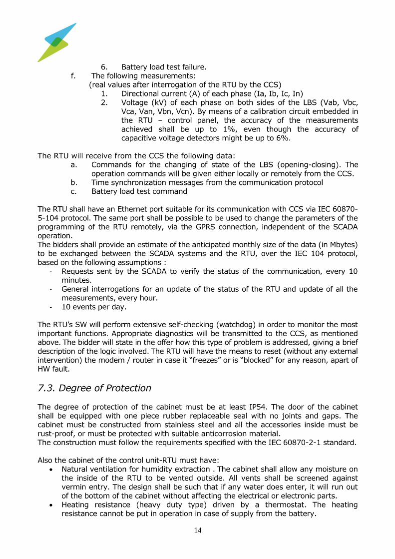
6. Battery load test failure. f. The following measurements:
(real values after interrogation of the RTU by the CCS)
1. Directional current (Α) of each phase (Ia, Ib, Ic, In) 2. Voltage (kV) of each phase on both sides of the LBS (Vab, Vbc,
Vca, Van, Vbn, Vcn). By means of a calibration circuit embedded in the RTU – control panel, the accuracy of the measurements
achieved shall be up to 1%, even though the accuracy of capacitive voltage detectors might be up to 6%.
The RTU will receive from the CCS the following data: a. Commands for the changing of state of the LBS (opening-closing). The
operation commands will be given either locally or remotely from the CCS. b. Time synchronization messages from the communication protocol c. Battery load test command
The RTU shall have an Ethernet port suitable for its communication with CCS via IEC 60870-
5-104 protocol. The same port shall be possible to be used to change the parameters of the programming of the RTU remotely, via the GPRS connection, independent of the SCADA operation.
The bidders shall provide an estimate of the anticipated monthly size of the data (in Mbytes) to be exchanged between the SCADA systems and the RTU, over the IEC 104 protocol,
based on the following assumptions : - Requests sent by the SCADA to verify the status of the communication, every 10
minutes.
- General interrogations for an update of the status of the RTU and update of all the measurements, every hour.
- 10 events per day. The RTU’s SW will perform extensive self-checking (watchdog) in order to monitor the most
important functions. Appropriate diagnostics will be transmitted to the CCS, as mentioned above. The bidder will state in the offer how this type of problem is addressed, giving a brief
description of the logic involved. The RTU will have the means to reset (without any external intervention) the modem / router in case it “freezes” or is “blocked” for any reason, apart of HW fault.
7.3. Degree of Protection The degree of protection of the cabinet must be at least IP54. The door of the cabinet
shall be equipped with one piece rubber replaceable seal with no joints and gaps. The cabinet must be constructed from stainless steel and all the accessories inside must be
rust-proof, or must be protected with suitable anticorrosion material. The construction must follow the requirements specified with the IEC 60870-2-1 standard.
Also the cabinet of the control unit-RTU must have: Natural ventilation for humidity extraction . The cabinet shall allow any moisture on
the inside of the RTU to be vented outside. All vents shall be screened against vermin entry. The design shall be such that if any water does enter, it will run out
of the bottom of the cabinet without affecting the electrical or electronic parts. Heating resistance (heavy duty type) driven by a thermostat. The heating
resistance cannot be put in operation in case of supply from the battery.

15
Additional protection on the inside, in order to allow operation of the LBS under all weather conditions, even when its front door is open for a short period of time during a manual operation.
7.4. Protection and safety The control cabinet shall have proper terminal for grounding all metal parts. It shall be fitted
with an external M12 earthing stud, with a nut, lock nut, and a serrated washer. Provision shall be made to ensure the electrical continuity of all exposed metal. Earthing
terminals shall be fitted to all such equipment. An earthing strap shall be provided between the lid and the tank of the cabinet.
The control cable shall be adequately earthed to shield the control equipment against electrical interference. The cabinet shall be suitably shielded so that the mounted GSM / GPRS antenna shall not
interfere with the normal operation of the equipment. Where minimum distance requirements for the mounting of an antenna apply, these shall be stated.
The control panel must comprise an adequate number of digital and analog inputs/outputs. Α galvanic isolation of the input/output cards must exist. The voltage isolation will be 2,5kV (rms).
Current monitoring circuitry in the most important parts of the RTU will be employed, in order to cut-off the supply in case the current exceeds the safety limits (i.e. presence of a short-
circuit). Also the control outputs will be protected against short-circuit, using proper fuses. Detailed information about these features will be included in the offer and in the RTU's documentation.
The Electronic circuits of the control panel (power supply, measurements ports etc.) shall have protection against overvoltage, spikes and transients.
8. RTU’s settings
The selection of the parameters of the below mentioned functions shall be done with two ways: (1) Through the control panel parameter configuration procedure and (2) by
downloading them to the RTU via the normal configuration procedure through a portable computer.
8.1. Directional function All overcurrent elements (phase, earth, SEF) shall be configured to be directional. Each overcurrent element shall have two independed groups of settings, the first for forward
direction faults and the second for reverse direction faults. Furthermore the RTU shall include directional blocking function to restrict the fault detection function (see § 8.5) and
the activation of sectionalizer function (see § 8.8) to a designated side of the LBS (source side or load side). The parameters of these functions (pickup settings, detection time,
characteristic angle, direction of activation i.e. forward or reverse etc.) shall be adjustable separately for phase, earth and SEF faults. The function shall be set ON or OFF. If it is set ON overcurrent elements shall operate only for the user selected direction (forward or
reverse) while by set it OFF overcurrent elements shall operate regardless of the fault current direction. Features shall be included to cope with insufficient voltage cases. The
manufacturer shall provide details to prove this.

16
8.2. Cold load pick up function
The RTU shall be equipped with Cold load pick-up function. Settings will be:
Multiplier adjustable from 1 to 5, with step 0,1
Time adjustable from 1 to 60 min, with step 1 min The function shall be set ON or OFF.
8.3. Open Line detection function (loss of phases) The RTU shall be equipped with Open Line detection function. Settings will be:
Volt ON from 50% to 90% of nominal voltage, with step 5%
Volt OFF from 35% to 75% of nominal voltage, with step 5% Delay time from 0,1 to 30 sec, with step 0,1 sec
The function shall be set ON or OFF.
8.4. Inrush restraint function The RTU shall be equipped with Inrush restraint function. Settings will be:
Percentage of 2nd harmonic from 5% to 50% of the fundamental frequency, with step 1%
Detect time 0,02 to 1 sec, with step 0,01 sec.
The function shall be set ON or OFF.
8.5 Fault detection function
Fault detection function is required for the RTU, regarding phase fault, earth-fault and Sensitive Earth Fault (SEF). This function shall be regulated ON or OFF independently for
phase fault, earth-fault and SEF.
The settings for this function will be: Adjustable, from 10 Α up to 1000 Α, with step of 1 Α for the phase fault. Adjustable, from 10 Α up to 1000 Α, with step of 1 Α for the earth fault.
Adjustable from 1 to 20 A, with step of 1 A, for the SEF. There shall be two independent stages for the SEF function. The first one (In>, t>) for sending an
alarm to the SCADA CCS and the second (In>>, t>>) for tripping of the LBS.
The time interval, for which the phase or earth or SEF fault must be sustained in order to be registered by the fault detecting circuitry. The time interval shall be
adjustable from 0,05 to 100 sec, with step of 0,01 sec for phase or earth fault and from 1 to 100 sec, with step 0,1 sec for SEF.
The RTU indicates phase or earth ”fault” when the line voltage is dropped below the voltage OFF-level of the Open Line Detection function after:
a. the measured phase current or earth current is higher than the pickup set value and maintains longer than the corresponding detection time and
b. certified that the measured phase or earth overcurrent isn’t an inrush or a cold load type overcurrent.
17
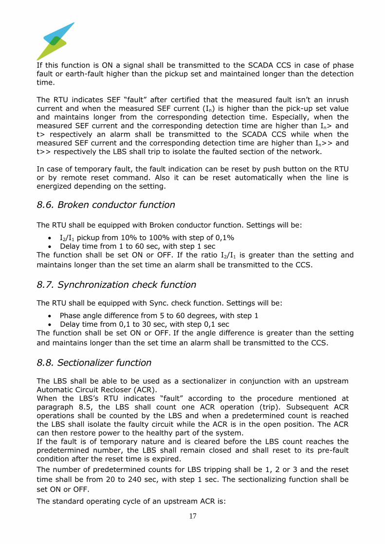
If this function is ON a signal shall be transmitted to the SCADA CCS in case of phase fault or earth-fault higher than the pickup set and maintained longer than the detection time.
The RTU indicates SEF “fault” after certified that the measured fault isn’t an inrush
current and when the measured SEF current (In) is higher than the pick-up set value and maintains longer from the corresponding detection time. Especially, when the
measured SEF current and the corresponding detection time are higher than In> and t> respectively an alarm shall be transmitted to the SCADA CCS while when the measured SEF current and the corresponding detection time are higher than In>> and
t>> respectively the LBS shall trip to isolate the faulted section of the network.
In case of temporary fault, the fault indication can be reset by push button on the RTU or by remote reset command. Also it can be reset automatically when the line is energized depending on the setting.
8.6. Broken conductor function The RTU shall be equipped with Broken conductor function. Settings will be:
I2/I1 pickup from 10% to 100% with step of 0,1% Delay time from 1 to 60 sec, with step 1 sec
The function shall be set ON or OFF. If the ratio I2/I1 is greater than the setting and
maintains longer than the set time an alarm shall be transmitted to the CCS.
8.7. Synchronization check function The RTU shall be equipped with Sync. check function. Settings will be:
Phase angle difference from 5 to 60 degrees, with step 1 Delay time from 0,1 to 30 sec, with step 0,1 sec
The function shall be set ON or OFF. If the angle difference is greater than the setting
and maintains longer than the set time an alarm shall be transmitted to the CCS.
8.8. Sectionalizer function The LBS shall be able to be used as a sectionalizer in conjunction with an upstream
Automatic Circuit Recloser (ACR). When the LBS’s RTU indicates “fault” according to the procedure mentioned at
paragraph 8.5, the LBS shall count one ACR operation (trip). Subsequent ACR operations shall be counted by the LBS and when a predetermined count is reached the LBS shall isolate the faulty circuit while the ACR is in the open position. The ACR
can then restore power to the healthy part of the system. If the fault is of temporary nature and is cleared before the LBS count reaches the
predetermined number, the LBS shall remain closed and shall reset to its pre-fault condition after the reset time is expired.
The number of predetermined counts for LBS tripping shall be 1, 2 or 3 and the reset
time shall be from 20 to 240 sec, with step 1 sec. The sectionalizing function shall be
set ON or OFF.
The standard operating cycle of an upstream ACR is:
18
- Instantaneous opening, Instantaneous reclosing. - Time delayed opening, 5 second reclosing - Time delayed opening, 5 or 10 second reclosing.
- Time delayed opening. The time delay of the delayed opening may reach up to 7 seconds.
8.9. Group settings There shall be at least four (4) different setting groups regarding the above mentioned
functions of paragraphs 8.1 to 8.8 and their different setting values can be stored individually. The user may select one of these 4 setting groups as active group, whose
setting values will be applied.
9. THREE CURRENT TRANSFORMERS (3 SINGLE PHASE)
The current transformers of paragraph 6.3.e. shall be in accordance with IEC standard
61869-2 and suitable to provide the functions as required by this TD. They shall be of 24 kV rated voltage and of a class and ratio adequate to ensure they do not saturate under fault conditions up to the full rated short time current. Current transformers
shall be thermally rated to LBS rated continuous current regardless of the ratio selected.
10. ONE VOLTAGE TRANSFORMER (DOUBLE PHASE) FOR
POWER SUPPLY
The voltage transformer must have the following characteristics:
Suitable for the operation conditions of paragraph 3 of the present TD Rated primary voltage: 24kV
Dry type cast resin are acceptable with resin insulation IEC standard 61869 -3 Two types of transformers shall be delivered:
- Single ratio 20/0,1 kV ac - Double ratio 20-15/0,1 kV ac.
The exact quantity of each type of transformer shall be mentioned in the Call of the Tender.
Rated output: enough for all the units operation
Accuracy: 5% Applied voltage 50 kV rms/1 min
Impulse voltage: 1,2/50 μs, 125kV, peak value
11. SIX ELECTRONIC VOLTAGE SENSORS (CAPACITIVE)
Line voltage shall be monitored on all six LBS bushings to allow remote monitoring of
voltage presence from either direction. The electronic voltage sensors of paragraph 6.3.f. shall have the following characteristics:

19
IEC 60044-7 standard 20kV or 15 kV nominal voltage
Integrated voltage sensors to provide voltage measurement Accuracy 6P over the operating temperature range.
Protection against electromagnetic noise Factory pre-calibrated
12. COMMUNICATION CAPABILITIES
12.1. Means of Communication The equipment (Control Panel / RTU) will communicate with the Central Control System (CCS) of a SCADA via GPRS using the IEC 60870-5-104 protocol. HEDNO will provide the
required SIM cards with a private APN network range and static IP addresses.
12.2 Communication with existing central control systems
HEDNO has in operation two types of CCSs. The Telegyr TG8000, that uses the IEC 60870-5-101 protocol and the EFACEC SCATEX+, that uses the IEC 60870-5-104
protocol. By the time of the installation of the first LBS, some of the Telegyr TG8000 systems will be replaced with a SIEMENS ST CCS, that will use the IEC 60870-5-104 protocol for communication with the LBS.
The contractor will have to implement the communication to the 3 SCADA systems,
mentioned above, based on the interoperability and address tables attached in the Call of Tender.
The communication between the Control panel-RTU and the SCADA of EFACEC and SIEMENS shall be direct and use IEC 60870-5-104 via GPRS. The communication between
the Control panel-RTU and the SCADA of Telegyr shall be performed via Protocol Converter (Gateway) as described in paragraph 13, for conversion of the protocol of the offered RTU to the IEC 101 of Telegyr. In this latter case, IEC 60870-5-104 via GPRS will
be used to communicate between Gateway and the Control panel-RTUs and a serial link with IEC 60870-5-101 between the Gateway and the Telegyr SCADA. (see attached figure
1). The SCADA system will interrogate each one of the LBS in a predefined time interval and
acquire the information described in par. 7.2. This time interval is user selectable per LBS from the SCADA system. The LBS will have to respond to these requests, but also
transmit events or alarms as they are generated.
13. PROTOCOL CONVERTER (Gateway)
The protocol converter (Gateway) must respect the following requirements:
1. Conversion of the IEC 60870-5-104 RTU protocol to IEC 60870-5-101 2. Each protocol converter (Gateway) shall be able to communicate with and
manage the data from at least 40 RTUs

20
3. The Gateway shall have at least 2 LAN ports available to communicate with the RTUs using a GPRS Router or an ADSL internet VPN connection.
4. The protocol converter (Gateway) shall be configurable with PC based
software. The software package will be provided by the supplier. The configuration will be saved in the PC as a portable file and can be downloaded
and uploaded from Gateway by the user. 5. The protocol converter (Gateway) must support at least the following
functions. a. Communication frame monitoring for master and slave protocol. b. Modem operation status monitoring.
c. Internal database monitoring. d. Internal database event display.
e. Internal database setting.
14. GSM/GPRS Routers The LBS will be equipped with a GSM/GPRS router, in order to communicate with
a CCS. During the tests (to verify the compatibility of the solution to the existing SCADA systems) and the final system configuration, the cellular network provider might not provide direct ADSL network connections to each one of the SCADA system
locations. The bidders must include in their offer at least 10 GSM/GPRS routers to be installed in the SCADA locations.
14.1. General Features
The routers shall be equipped as a minimum with the following characteristics:
- Bands: at least GSM/GPRS: 900/1800 MHz - Minimum output power: Class 4 (2W) for 900MHz, Class 1 (1W) for 1800MHz - GPRS class 12: DL: max. 85.6 kbps, UL: max. 85.6 kbps
- CSD data transmission 14.4 kbps, V.110 - Profile-managed packet data connections
- Support of Roaming for flawless network connection to any provider. This means that in case of GPRS communication fault from one carrier, the modems shall support automatic roaming functions between any other available carriers.
- NAT disable for framed route configuration - Transparent bridge mode using PPPoE to allow the router to transparently forward
public WAN IP address to a downstream device - SIM security management (PIN configuration, enable and disable)
- Static routing, port forwarding - VRRP functionalities for redundant router failover - VPN functions that will include :
o PPTP client for VPN connectivity to remote PPTP VPN server o IPSec tunnel termination (for up to 5 tunnels)
o GRE tunnelling o Open VPN (client, server and P2P)
- Power supply: From 12V DC up to 24V DC, with protection from overvoltage and
reverse polarity. - LED operation indications for visual inspection, of power status, of the connection
status, and the connected network type (GSM/GPRS/EDGE/3G).

21
- Web-based user interface (HTTP/HTTPS) for full device status and configuration - SMS client (for reset function using SMS) - Ping monitor watchdog (reset connection or modem on repeated ping failure)
- NTP server support for device system clock network time sync - Support for up to regular SIM size
- Reset button - 1x SMA connector for optional external main antenna
- Operating conditions: o Temperature: -20o C - +65o C o Humidity: up to 92% RH
14.2 Standards–Specifications–Instructions According to the ETS 300-342-1
According to Directive 89/336/EEC, on electromagnetic compatibility According to Directive 98/13/EEC, on telecommunication terminal equipment
14.3. Antenna Omni-directional
SMA plug Gain >4dBi Dual Band (900/1800 MHz)
Available with at least 3m cable, in case placed outside the RTU casing. Equiped with a mounting bracket
14.4. Installation
In the offer shall be included the necessary connectors, cables, etc. for the mounting of
the device in the RTU cabinet and the corresponding antenna too.
14.5. Special Terms
The supplier must provide the technical manuals of the devices and antennas and the installation and user’s instructions. Operation and troubleshooting manuals shall be provided in Greek language. All other manuals (Engineering, User, Programming etc.)
may be only in English. The technical solution will include the telecommunication equipment (modem/router).
15. TESTS
15.1 Type tests The following type tests shall be carried out at the beginning of the execution of the contract, prior to the delivery of the first lot (and prior to lot acceptance tests). During
the period of the validity of the contract, no modification to the study, planning and construction of the equipment is permitted without prior approval by HEDNO. In case of

22
any modifications detected, new type tests shall be repeated at the absolute discretion of HEDNO. In case that the type tests reports or the detailed type test certificate (that have been
already submitted as per paragraph’s 17 requirements of the present TD) correspond to the identical equipment type offered, the execution of the below mentioned type tests
shall not burden the Contractor. This is in the case that the tests are successful, according to the relevant paragraph of the special terms of the Tender.
The type tests shall be carried out in nationally or internationally recognized laboratories, EN 17025 accredited. The test laboratory, the tests time schedule as well as the number of samples shall be proposed from the Contractor to be approved by
HEDNO’s Inspection Service within fifteen (15) days from the effective date of the Contract. Regardless of the tests time schedule, the Contractor shall have available
samples of the equipment (LBS, RTU, supply voltage transformer etc.) ready to be shipped to the test laboratory within two (2) months from the effective date of the Contract.
HEDNO will request the execution of the below mentioned type tests to the test laboratory which will then send the results of the type tests directly to HEDNO.
In case of failure of the type tests, HEDNO will denounce the Contract due to culpability of the Contractor.
The contractual time of equipment delivery will begin on the issuing date of the results
of successful type tests by the test Laboratory. It is clarified that the time required for type testing, issue of the relevant test reports and tests evaluation will extracted from
the delivery schedule, i.e. the delivery time will be extended equally to the time required for the testing.
The costs for the samples as well as their transport to the test laboratory will be charged
to the Contractor in both cases of results (failure or success of the tests).
15.1.1. Type tests for LBS and its auxiliary and control circuits
1. Dielectric tests in accordance with the paragraph 6.2 of IEC 62271-103.
2. Measurement of the resistance of circuits in accordance with the paragraph 6.4 of IEC 62271-103.
3. Temperature rise test in accordance with the paragraph 6.5 of IEC 62271-103.
4. Short time withstand current 12,5 kA, 1s and peak withstand current 31,25 kA tests in accordance with the paragraph 6.6 of IEC 62271-103.
5. Verification of the protection in accordance with the paragraph 6.7 of IEC 62271-103.
6. Mechanical operation test at ambient air temperature, mechanical endurance tests for M2 class switches, in accordance with the paragraph 6.102.2 of IEC 62271-103.
7. Making and breaking tests in accordance with the paragraph 6.101 of IEC 62271-103. All breaking tests shall be carried out on a single breaker and all making tests
on another piece. 8. Tightness test for SF6, insulated LBS after the mechanical operation test above, in
accordance with the paragraph 6.8 of IEC 62271-103.
9. Electromagnetic compatibility (EMC) tests in accordance with the paragraph 6.9 of IEC of 62271-103.
10. Additional tests on auxiliary and control circuits in accordance with the paragraph 6.10 of IEC 62271-103.

23
11.Low and high temperature tests in accordance with the paragraph 6.102.3 of IEC 62271-103.
12.Operation test for position indicator of the LBS in accordance with the paragraph
6.102.6 of IEC 62271-103. 13.X-radiation test for vacuum LBS in accordance with the paragraph 6.11 of IEC
62271-103.
15.1.2. Type tests for the supply voltage transformer
Type tests for the supply voltage transformer in accordance with IEC 61869-3.
15.1.3. Additional type tests for auxiliary and control circuits
1. Insulation breakdown voltage test on auxiliary and control circuits in accordance with IEC 60255-5 (a) Supply voltage
Class VW3, IEC 60870-2.1 (2.5 kV rms/50Hz/1 min). (b) Digital inputs
Class 3, IEC 60870-3, table 6 (2,5 kV rms/50 Hz/1 min) (c) Analogue inputs Class 2, IEC 60870-3, table 7 (0,5 kV/DC/1 min)
2. DC impulse voltage withstand test on auxiliary and control circuits in accordance with IEC60255-5
(a) Supply voltage Class VW3, IEC 60870-2-1 (5 kV/1,2/50 μs) and Class III, IEC 255-4 (5 kV single
HV impulse) (b) Digital inputs Class 3, IEC 60870-3, (table 6) and Class III, IEC 255-4 (5 kV single HV impulse)
(c) Analogue inputs Class 2, IEC 60870-3, (table 7) and Class II, IEC 255-4 (2 kV single HV impulse)
15.2 Routine tests Routine tests shall be carried out at manufacturer’s premises and the relevant test
protocols shall be provided to the assigned inspector. The routine tests are the following:
1. Dry, short duration power-frequency withstand voltage applied on the main circuit. Test voltage 50 kV rms, 1 min between the phases and the earth and
60 kV rms, 1 min across the isolating distance, in accordance with the paragraph 7.1 of IEC 62271-1.
2. Tests on auxiliary and control circuits, in accordance with the paragraph 7.2 of
IEC 62271-1. 3. Measurement of the resistance of the main circuit in accordance with the
paragraph 7.3 of IEC 62271-1. The value of the resistance measured shall not exceed 120% of the relevant value measured during the type tests.
4. Tightness test for SF6 insulated LBS in accordance with the paragraph 7.4 of
IEC 62271-1. 5. Design and visual checks in accordance with the requirements of the present
TD.

24
6. Mechanical operation tests in accordance with the paragraph 7.101 of IEC 62271-103.
7. Routine tests for the supply voltage transformer in accordance with IEC 61869-3
at the premises of the transformer manufacturer.
15.3 Sample tests (Factory Acceptance Tests - FAT)
These tests shall be performed in presence of HEDNO’s personnel at the manufacturer’s premises, prior to delivery, after successful routine testing performed
on each specimen of the batch done by the supplier. The assigned HEDNO’s inspector shall select a random sample from any lot under
delivery based on IEC 410 plans, simple or double sampling, normal inspection, inspection level II, AQL=2,5%, on which all the tests described in the paragraph 15.2 above shall be successfully carried out.
Also a full operation check must be carried out to ensure that the system (LBS, Control cabinet, RTY etc.) operates according to the present TD. Operational checking
must be done using simulation techniques at the premises of the supplier. The supplier has to propose the procedure and duration of such tests. HEDNO has the
right to modify these procedures, up to 30 days prior to the inspection period.
16. LBS SIMULATOR EQUIPMENT LBS simulator equipment shall be provided, for the purpose of testing the configuration, of the SCADA software and the controller of the LBS. The simulator
shall provide to the controller all the digital indications of the status of the LBS, the analog measurements, as well as to simulate all fault conditions of the
network, that are predicted by this tender. It will also execute all commands available for the LBS and shall provide feedback to the controller of the status of the LBS. This simulator equipment will allow HEDNO personnel to perform all tests required, to
ensure that the SCADA system and the LBS controller are properly configured, prior to the LBS installation.
17. SPARE PARTS
The bidders must attach a complete list of spare parts. The spare parts list must include all the items of the LBS and the RTU (cards of RTU, modules, interconnecting flat cables
etc.) with their unit prices. The bidder will provide the spare parts mentioned at the Call of each Tender.
The price of the spare parts must be included only in the economical evaluation. In the bid there must be a three year guarantee for all spare parts from the dispatch time. There will be at least 10 years availability period of all spare parts.
All acquired spare parts will be tested during the Guarantee period. The test will be done
by installing them in the commissioned units, replacing those which are already functioning. Any spare part found faulty at the first test will have to be replaced by the
supplier free of charge.

25
18. SPECIAL INFORMATION THAT MUST BE GIVEN WITH THE
BID - REFERENCES
Every bid must be followed with the underneath information–in other case the offer will
be rejected:
Typical drawings, leaflets, etc. that show characteristics of the offered units,
their dimensions and proposed installation layouts with instructions. Maintenance instructions.
Certificates to ensure that the units comply with the IEC standards mentioned in this technical description.
A declaration of conformity of the material offered with the requirements of
the present TD. Any discrepancies shall be clearly and thoroughly reported. • Type tests reports for the LBS and its control panel/RTU as well as for the
supply voltage transformer, issued by nationally or internationally recognized laboratories EN 17025 accredited. The type tests for the LBS and the control panel/RTU shall concern at least the tests of paragraph 15.1.1 of
the present TD. The type tests reports for the tests No 1, 2, 3, 4, 5, 6, 7, 8, 9 and 12 of paragraph 15.1.1 shall be strictly in accordance either to IEC
62271-103 or IEC 60265-1, while the type tests reports for the tests No 10, 11 and 13 (if applicable) of paragraph 15.1.1 shall be strictly in accordance with IEC 62271-103. The type tests reports for the supply voltage
transformer shall be strictly in accordance with IEC 61869-3 and shall concern the totality of IEC 61869-3 type tests.
It is understood that detailed type test certificate issued by nationally or internationally recognized laboratories, EN 17025 accredited, strictly in accordance with IEC 62271-103 for the LBS and its control panel/RTU and
with IEC 61869-3 for the supply voltage transformer, is also acceptable. The Bidder shall certify the type tests reports or the detailed type test
certificates as true copies of the original. It is explicitly stated that after the signing of the contract any tests of
paragraph 15 of the present TD are performed (type tests, routine tests and sample tests) of the LBS and the supply voltage transformer shall be carried out in accordance with the IEC 62271-103 and the IEC 61869-3
respectively, as it is clearly mentioned in this paragraph. A statement that upon receipt the labels of the control panel (buttons,
switches, LEDs etc.) shall be written in Greek language. A statement that the design of the LBS and the RTU shall allow the
replacement of either part, without the need of calibrating any of the units.
Any adjustments required to ensure the accurate measurements of voltages and currents might include only the use of portable electronic device or
laptop and no measurement instruments. The Bidder shall provide enough reference to prove the above.
Each bidder must submit with his offer, with rejection of the offer under failure of
submission, the following:
a. The bidder must complete a detailed compliance table with the technical description per paragraph.

26
b. Must have ISO 9001 for the design, manufacturing, testing and servicing of LBS and their related control equipment.
c. The manufacturer must have references from Utilities (name of the Utility,
address, phone number, fax number, e-mail etc), for the same or similar LBS (voltage, rated current, short circuit current equal or higher than 20kV,
630A, 12,5kA respectively). In the reference letters, the buyer, the type of LBS, the quantity, the date of delivery and the country of installation shall be
mentioned, as well as, whatever information is deemed to be useful for proving the long term successful operation of the material. The units must be installed in the last 3 years and operate satisfactory. The number of the
units must be at least equal to the half of the number of the tender. As proof original or true copies of Appreciation letters are preferred but copies of
sales contract are also accepted. In case of orders awarded by Utilities to Third Parties, such as in the case of indirect order to the LBS manufacturer, as proof of experience will be submitted true copies of the contract between
the Utility and the Third Parties as well as that between the Third Parties and the manufacturer.
d. Must provide a detailed description on methodology to implement communication between the offered RTU on the field with two concurrent SCADA systems (Efacec and Siemens).
e. Declaration of the factory where the product is manufactured, with analytical information (Full address, number of employees, a brief description of the
installations, testing capabilities). The factory shall possess the following certifications and capabilities and provide the relevant certificates:
o ISO 9001 certification of the manufacturer, with a certification scope
including the LBS’s. The certificate shall be guaranteed by the manufacturer, which shall also provide communication data for the
Certification Body together with its accreditation certificate, or any other data requested during the technical evaluation of the offer, facilitating the examination of the soundness of the certificate.
o Adequacy of the testing equipment for routine and lot acceptance testing.
o A declaration of the manufacturer of the insulators offered and the relevant data regarding quality certification, if requested.
HEDNO reserves the right to examine on site the production and the rest
capabilities of the manufacturer of the LBS. f. For the type of insulators offered References (sales list, reference letters
homologations) from Utilities (name, address, phone number, fax number, e-mail, etc.), proving that the manufacturer is in uninterrupted operation and produced at least 6.000 pieces of the identical type as that offered, and
that these insulators are operating successfully in the network, during the last 3 years, as minimum. Separate proof of references of the insulator
experience is not required provided manufacturer states that the insulators offered are the same included in the references provided against position
17.c above. g. The manufacturer of the supply voltage transformer must have references
from Utilities (name of the Utility, address, phone number, fax number, e-
mail etc), for the same or similar supply voltage transformers (with equal or higher rated voltage and rated output). In the reference letters, the buyer,
the type of transformer, the quantity, the date of delivery and the country of installation shall be mentioned, as well as, whatever information is deemed to

27
be useful for proving the long term successful operation of the material. The units must be installed in the last 3 years and operate satisfactory. The number of the units must be at least equal to the half of the number of the
tender. As proof original or true copies of Appreciation letters are preferred but copies of sales contract are also accepted. In case of orders awarded by
Utilities to Third Parties, such as in the case of indirect order to the transformer’s manufacturer, as proof of experience will be submitted true
copies of the contract between the Utility and the Third Parties as well as that between the Third Parties and the manufacturer.
19. DOCUMENTATION
The supplier must provide, for approval by HEDNO within 30 days from the effective date of the contract, three complete sets of the documentation for all units, in hardcopy and in
electronic form. The documentation must include:
Description of all offered units
Description of the operation of all units The drawing of the electronic parts of the units which will describe in every
detail the internal wiring of the RTU cabinet with its terminal blocks and connectors
Block diagrams of the various HW modules of the RTU showing the way
they are interconnected and the connections between RTU – LBS Maintenance instructions
20. TRAINING The supplier will provide for HEDNO four (4) courses of training, each one lasting five (5) days, at different geographical sites in Greece (i.e. Athens, Thessalonica, Patras,
Lamia) and at different time intervals, and additionally, six (6) months after the end of the 4th training course, one more training course, lasting three (3) days, in order to
resolve any outstanding issues and problems encountered. HEDNO and the supplier will agree on the most convenient time for the courses, but that period must be within two (2) months from the delivery time of the first partial delivery.
One RTU and all the necessary equipment (protocol converter (Gateway), modems etc.) and documentation will be used for this training.
The training shall include, at least, the following:
The RTU HW components piece by piece
The RTU's SW main functions The function of the RTU as a unit
Description of the communication software Maintenance of the unit Operation of the LBS
The function and maintenance of the protocol converter Programming and use of the Breaker simulator.

28
21. GUARANTEE
The guarantee period will be three (3) years at maximum for all units supplied. The
guarantee period will start from the date of installation and shall not exceed five (5) years from the date of delivery. HEDNO will provide upon request of the Supplier proof of the date of installation of the LBSs.
The supplier must be fully responsible for the proper operation of all the units for the
guaranteed period. During the guarantee time period the supplier, free of charge will: • Intervene to correct any RTU SW fault which will be found. The same is also
valid for the protocol converter SW.
• Correct any communication problems that may arise (due to the equipment supplied).
• Correct any error or omission which will be found in the documentation. • Respond to any information required by HEDNO. • Make any modification requested, which will improve the RTU's compliance
to the specifications.
All costs resulting to HEDNO from replacing any faulty equipment (LBS and RTU) both of removing and reinstalling within the guarantee period will be held from the letter of Guarantee. The Supplier will have to replace within 2 months the parts used, from the
HEDNO’s Lot of Spare Parts, with the repaired or new part. For every month of delay to replace in time, the part used from HEDNO’s Lot, the price of the item will be held
from the letter of guarantee. In case a spare part is not available in HEDNOs warehouses the supplier has to provide it to HEDNO within 15 working days.
Regarding the interventions to correct any RTU and protocol converter SW fault the following will apply:
• Maximum time for answering to HEDNO (notice of a problem) to the telephone, FAX or e-mail : 2 h, from 8 a.m. to 3 p.m. from Monday to Friday,
except official holidays, as they apply to Greece.
• Maximum time between acknowledging the problem reported above by HEDNO until the arrival to HEDNO’s Local Unit in order to visit the site escort
by HEDNO’s personnel : 15 working days (in case the intervention has to be supplied to all locations shall be concluded within 3 months).
• Maximum time between on-site intervention and resolution of the problem (return to repair conditions): 2 working days.
Failure to provide support within the above mentioned times, will incur a fine of 250,00€ per day of delay. For intermediate delays (e.g. hour, day section) the fine will
be determined by linear interpolation. In case of simultaneous events the Supplier shall proceed to interventions and
corrective actions in a sequentially manner. The Supplier won't be responsible for any delays regarding compliance with the maximum times mentioned above, if those delays result from force majeure cases.
The Supplier shall notify HEDNO, by registered letter, in the advent of any situations mentioned in the previous clause immediately or in any case within 15 days from the
occurrence date, if all other means were tried to avoid or minimize the delay in the promised obligations. The Supplier has the sole responsibility of employing its personnel according to all
the legal requirements and providing all personal and health insurance for him.
29
HEDNO could not be held liable for any injuries or compensation to the personnel of the Supplier. At the end of the guarantee period, HEDNO and the supplier will sign a protocol on the
equipment's behavior for the release of the Letter of Guarantee.
22. NAMEPLATES AND MARKING
The LBS, the control panel and the auxiliary power supply VT shall carry a nameplate, suitable to withstand the environmental conditions, at a position visible at normal
operation position, with engraved letters. The LBS nameplate shall include at least the following data:
Name or trademark and address and phone of the manufacturer Date of manufacture, product type and serial number
Contract number Class of the LBS according ΕΝ 62271-103 (E3, M2) Rated voltage (kV)
Rated continuous current (A) Rated frequency (Hz)
Rated short time withstand current and duration (kA rms, sec) Rated short circuit making current (kAp) Rated impulse withstand voltage 1,2/50 μs (BIL):
Between phases and the earth (kVp) across the isolating distance (across the terminals of open switch, of same
phase) (kVp) Weight (kg)
The control panel nameplate shall include at least the following data: Name or trademark and address and phone of the manufacturer
Date of manufacture, product type and serial number Contract number CE marking
Weight (kg)
The auxiliary power supply VT name plate shall include at least the following data: Name or trademark and address and phone of the manufacturer
Date of manufacture, product type and serial number Contract number Primary and secondary rated voltages (kV)
Rated power (VA) Rated frequency (Hz)
Accuracy Class
Rated impulse withstand level (kVp) Weight (kg)

30
23. PACKING The equipment shall be packed in durable wooden cases of suitable dimensions, with
all sides totally closed. The cases shall withstand external environmental conditions, like rain, humidity, ambient temperatures etc. The packing shall ensure that the equipment shall be protected against damages
during transportation, loading and unloading. The wooden cases shall be packed together on EU type pallets and the total weight of pallet one shall not exceed 550 Kg.
On two opposite sides of each case the following data shall be marked in a clear and indelible way:
Manufacturer / Year of manufacture / Contract Number Description, type and serial number of contents
HEDNO material code number Gross weight in kg
Attached:
- Figure No 1:Communication between the Control panel-RTU and the HEDNO’s
SCADA CENTRAL Control Systems - Figure No 2: MV lightning arrester bracket - Drawings Nr F-5, FCP-4 & FCP-5 - Indicative construction drawing of a telecontrolled load break switch - PPC/ΧΚ 11.02/11.03.2008: Hot dip galvanizing in iron and steel hardware

31
Figure 1 Communication between the Control panel-RTU
and the HEDNO’s SCADA Central Control Systems
GATEWAY
CCS SIEMENS
ST
LBS #1
LBS #3000
CCS TELEGYR TG8000
CCS EFACEC
SCATEX +
IEC 104
IEC 104
IEC 104
IEC 101
After SCADA
Transition


55 1
Medium & Heavy Wooden Poles of 12 ÷ 15 m length are used for L/B
mounting
Pole’s min diameter (cm)
MV Wooden
Pole
Pole Category
Heavy Medium Light
Distance from the
upper end

55 2
Max diameter of pole’s upper end Diameter’s increment
Categories of concrete poles for L/B mounting
Pole’s length (m) increment
Max diameter of pole’s upper end Diameter’s increment

55 3
Diameter of holes : 22 mm
Distance
between holes is 300 mm
MV concrete poles

55 4
ΕΝΔΕΙΚΤΙΚΟ ΣΧΕΔΙΟ ΚΑΤΑΣΚΕΥΗΣ ΕΝΟΣ ΤΗΛΕΧΕΙΡΙΖΟΜΕΝΟΥ ΔΙΑΚΟΠΤΗ ΦΟΡΤΙΟΥ INDICATIVE CONSTRUCTION DRAWING OF A TELECONTROLLED LOAD BREAK SWITCH