
NORME CE1 IEC INTERNATIONAL 71 STANDARD...
51
IEC 71 PT81 93 Ez1 4844833 0544786 565 E! NORME INTERNATIONALE INTERNATIONAL STANDARD CE1 IEC 71 -I Septieme Bdition Seventh edition 1993-1 2 Coordination de l’isolement Partie 1 : Définitions, principes et règles Insulation co-ordination Part 1: Definitions, principles and rules Numéro de reference Reference number CElllEC 71 -1: 1993 COPYRIGHT International Electrotechnical Commission Licensed by Information Handling Services COPYRIGHT International Electrotechnical Commission Licensed by Information Handling Services
Transcript of NORME CE1 IEC INTERNATIONAL 71 STANDARD...

IEC 71 P T 8 1 93 Ez1 4 8 4 4 8 3 3 0544786 5 6 5 E!
NORME INTERNATIONALE INTERNATIONAL STANDARD
CE1 IEC 71 -I
Septieme Bdition Seventh edition
1993-1 2
Coordination de l’isolement
Partie 1 : Définitions, principes et règles
Insulation co-ordination
Part 1: Definitions, principles and rules
Numéro de reference Reference number
CElllEC 71 -1: 1993
COPYRIGHT International Electrotechnical CommissionLicensed by Information Handling ServicesCOPYRIGHT International Electrotechnical CommissionLicensed by Information Handling Services
IEC 71 P T * l 9 3 E 3 4 8 4 4 8 9 3 0 5 4 4 7 8 7 4TL m
Révision de la présente publication
Le contenu technique des publications de la C E I est cons- tamment revu par la Commission afin d’assurer qu’il reflète bien I’ktat actuel de la technique.
Les renseignements relatifs h ce travail de revision, à I’Ctablissement des editions révis6es et aux mises àjour peuvent être obtenus auprès des Comites nationaux de la C E I et en consultant les documents ci-dessous:
Bulletin de la C E I
Annuaire de la C E I
Catalogue des publications de la C E I Publik annuellement
Terminologie
En ce qui cancerne la terminologie gknkale. le lecteur se reportera A la Publication 50 de la C E I : Vocabulaire Electrotechnique International (VEI), qui est etablie sous f o m e de chapitres dpar6.s traitant chacun d’un sujet defini, l’Index gC- n6ral ktant publié &parCrnent Des details complets sur le VE1 peuvent ême obtenus sur demande.
Les termes et definitions figurant dans la prksente publication ont CtC soit repris du VEI, soit #cifiquement approuvés aux fins de cette publication.
Symboles graphiques et littéraux
Pour les symboles graphiques, symboles 1ittCraux et signes d’usage général approuvés par la C E I , le lecteur consultera:
- Ia Publication 27 de la C E I : Symboles linCraux à utiliser en électrotechnique;
- la Publication 617 de la C E I: Symboles graphiques pour schémas.
Les symboles et signes contenus dans la présente publication ont kté soit repris des Publications 27 ou 617 de la C EI, soit spkifiquement approuves aux fins de cette publication.
Publications de la C E I établies par le même Comité d’Etudes
L’attention du lecteur est attirke sur le deuxième feuiller de la couverture. qui Cnumère les publications de la C E I préparées par le Comite d’Etudes qui a établi la prksente publication.
Revision of this publication
The technical content of I E C publications is kept under con- stant review by the I E C, thus ensuring that the content reflects current technology.
Information on the work of revision, the issue of revised edi- tions and amendment sheets may be obtained from I E C National Committees and from the following I E C sources:
I E C Bulletin
I E C Yearbook
Catalogue of I E C Publications Published yearly
Terminology
For general terminology, readers are referred to I E C Publi- cation 50: Intemational Electrotechnical Vocabulary @V), which is issued in the form of separate chapters each dealing with a specific field, the General Index being published as a se- parate booklet. Full details of the IEV will be supplied on request.
The terms and definitions contained in the present publication have either been taken from the IEV or have been specifically approved for the purpose of this publication.
Graphical and letter symbols
For graphical symbols, and letter symbols and signs approved by the I E C for general use, readers are referred to:
- I E C Publication 27: Letter symbols to be used in electrical technology;
- I E C Publication 617: Graphical symbols for diagrams.
The symbols and signs contained in the present publication have either been taken from I E C Publications 27 or 617, or have been specifically approved for the purpose of this publication.
I E C publications prepared by the same Technical Committee
The attention of readers is drawn to the back cover, which lists I E C publications issued by the Technical Committee which has prepared the present publication.
COPYRIGHT International Electrotechnical CommissionLicensed by Information Handling ServicesCOPYRIGHT International Electrotechnical CommissionLicensed by Information Handling Services
NORME INTERNATIONALE INTERNATIONAL STANDARD
CE1 IEC 71 -1
Septieme bdition Seventh edition
1993-1 2
Coordination de l'isolement
Partie 1 : Définitions, principes et règles
Insulation co-ordination
Part 1: Definitions, principles and rules
@ CE1 1993 Droits de reproduction réservés - Copyright - all rights reserved
Aucune partm de œ(fe prblicalbn ne peut êIre reprodule nl No part of thus pubIlcation may be reproduced or Ulilued in u l 1 1 1 s é e sous quelque forme que ca soit d p a r aucun pro- any form or by any means, electronic or mrchanlcal. d.. électronque ou mécanique. y mnpns h phdocopie e( ncludng photocopying and Mcrolih, without pamission les mrofilms. sans l'accord h i i l de I'édditeur. YI writmg from the prbl'her
Bureau Central de la Commission Electrdedrnique Internationale 3. rue de Varembe Genève. Suisse
Commission Electrotechnique Internationale CODE P R I X International Electrotechnical Commission P R I C E CODE T MemnvHaponHaFI 3ne~rporex~~.tecna~ HOMMCWR
Pour prm. voir caralcgue en vigueur For prrce. see currenr caralogue
COPYRIGHT International Electrotechnical CommissionLicensed by Information Handling ServicesCOPYRIGHT International Electrotechnical CommissionLicensed by Information Handling Services
IEC 71 PT*3 73 E! 4 8 4 4 8 9 3 0544789 2 7 4 E'!
- 2 -
SOMMAIRE
71 -1 0 CEI:1993
Pages
AVANT-PROPOS ...................................................................................................................... 6 Artides
1 Domaine d'application ...................................................................................................... 8
2 References normatives .................................................................................................... 8
3 DQfinitions .......................................................................................................................... 10
3.1 Coordination de l'isolement ...................................................................................... 3.2 Isolation externe ....................................................................................................... 3.3 Isolation interne ........................................................................................................ 3.4 Isolation autor4gbneratrice ....................................................................................... 3.5 Isolation non autoreghneratrice ................................................................................ 3.6 Borne de la configuration de l'isolation ..................................................................... 3.7 Configuration de l'isolation ....................................................................................... 3.8 Tension nominale d'un reseau ................................................................................. 3.9 Tension la plus 6lev6e d'un reseau .......................................................................... 3.1 O Tension la plus hlevée pour le materiel (U, ) ............................................................ 3.1 1 Reseau a neutre isole ...............................................................................................
3.13 RBseau compense non directement A la terre .......................................................... 3.1 4 Réseau compense par bobine d'extinction ...............................................................
3.1 2 Reseau A neutre directement A la terre ....................................................................
3.15 Facteur de defaut A la terre ...................................................................................... 3.1 6 Surtension ................................................................................................................ 3.17 Classification des tensions et des surtensions ......................................................... 3.1 8 Formes de tension normalisées ............................................................................... 3.1 9 Sufiensions représentatives (U ) ............................................................................ 3.20 Disposfiif de limitation des surtensions ..................................................................... 3.21 Niveau de protection aux chocs de foudre (ou de InanOeuvre) ................................ 3.22 Critère de performance ............................................................................................. 3-23 Tension de tenue ...................................................................................................... 3.24 Tension de tenue de coordination (ucw) ................................................................... 3.25 Facteur de coordination (Kc) .................................................................................... 3.26 Conditions atmosphériques normalisées de reference ............................................ 3.27 Tension de tenue specifiee (u, ) ............................................................................. 3.28 Facteur de correction atmosphérique (Ka) ............................................................... 3-29 Facteur de securaé (&) ........................................................................................... 3-30 Tension de tenue normalisée (u ) ........................................................................... 3-31 Facteur de conversion d'essai (K,) ........................................................................... 3.32 Niveau d'isolement assigne ...................................................................................... 3.33 Niveau d'isolement normalisé ................................................................................... 3.34 Essais de tension de tenue normalisés ....................................................................
rP
W
10 10 10 10 10 10 10 12 12 12 12 12 12 12 12 12 14 14 16 16 16 16 16 16 18 18 18 18 18 18 18 18 18 18
COPYRIGHT International Electrotechnical CommissionLicensed by Information Handling ServicesCOPYRIGHT International Electrotechnical CommissionLicensed by Information Handling Services

I E C 7L P T * L 9 3 H 4844833 0544790 T96
71-1 O IEC:1993 - 3 -
CONTENTS
Page
FOREWORD .............................................................................................................................. 7 Clause
1 Scope ................................................................................................................................. 9
2 Normative references ....................................................................................................... 9
3 Definitions .......................................................................................................................... 11
3.1 Insulation co-ordination ............................................................................................ 11 3.2 External insulation .................................................................................................... 11 3.3 Internal insulation ..................................................................................................... 11 3.4 Self-restoring insulation ............................................................................................ 11 3.5 Non-self-restoring insulation ..................................................................................... 11 3.6 Insulation configuration terminal ............................................................................... 11 3.7 Insulation configuration ............................................................................................. 11
3.9 Highest voltage of a system ..................................................................................... 13 3.10 Highest voltage for equipment (U ) ......................................................................... 13 m 3.1 1 Isolated neutral system ............................................................................................. 13
3.13 Impedance earthed (neutral) system ........................................................................ 13 3.14 Resonant earthed (neutral) system .......................................................................... 13
3.16 Overvottage .............................................................................. : ............................... 13
3.1 8 Standard voltage shapes .......................................................................................... 15
3.19 Representative overvoltages ( U ) ........................................................................... 17
3.21 Lightning (or switching) impulse protective level ...................................................... 17 3.22 Performance criterion ............................................................................................... 17 3.23 Withstand voltage ..................................................................................................... 17
3.25 Co-ordination factor (Kc) ........................................................................................... 19 3.26 Standard reference atmospheric conditions ............................................................. 19 3.27 Required withstand voltage ( U ) ............................................................................. 19 3.28 Atmospheric correction factor (Ka) .......................................................................... 19 3.29 Safety factor (K, ) ...................................................................................................... 19 3.30 Standard withstand voltage (U,,, ) .............................................................................. 19
3.32 Rated insulation level ............................................................................................... 19 3.33 Standard insulation level .......................................................................................... 19
3.8 Nominal voltage of a system .................................................................................... 13
3.1 2 Solidly earthed neutral system ................................................................................. 13
3.15 Earth fault factor ....................................................................................................... 13
3.1 7 Classification of voltages and overvoltages .............................................................. 15
rp 3.20 Overvoltage limiting device ....................................................................................... 17
3.24 Co-ordination withstand voltage (U, ) ...................................................................... 17
rw
3.31 Test conversion factor (y) ........................................................................................ 19
3.34 Standard withstand voltage tests .............................................................................. 19
COPYRIGHT International Electrotechnical CommissionLicensed by Information Handling ServicesCOPYRIGHT International Electrotechnical CommissionLicensed by Information Handling Services
- 4 - 71-1 O CEIl1993
Articles Pages
4 Procedure pour la coordination de l'isolement ............................................................. 20
4.1
4.2 4.3 4.4 4.5 4.6
4.7 4.8 4.9
GBneralites sur la procedure ............................................................................... Determination des surtensions representatives (Urp) ...................................... Determination des tensions de tenue de coordination (U,, ) .......................... Determination des tensions de tenue spbcifiees (U,,,, ) .................................... Choix du niveau d'isolement assign6 ................................................................. Liste des tensions de tenue normalisees de courte duree a frequence industrielle ............................................................................................................. Liste des tensions de tenue aux chocs normalisees ........................................ Gammes de tension la plus Blevee pour le materiel ........................................ Choix des niveaux d'isolement normalises ........................................................
20 20 22 22 24
24
26 26 26
5 Prescriptions pour les essais de tension de tenue normalises ................................... 28
5.1 5.2
5.3 5.4 5.5
5.6
G6neralitBs ............................................................................................................ 28 Essais normalis& de tension de tenue de courte durke 8 frequence industrielle ........................................................................................... 30
Essais normalises de tension de tenue aux chocs ........................................... 30 Situation d'essai differente .................................................................................. 32 Essais normalises de tension de tenue de l'isolation entre phases et de l'isolation longitudinale pour le materiel de la gamme I .................................. 32
Essais normalis6s de tension de tenue de l'isolation entre phases et de l'isolation longitudinale pour le materiel de la gamme I I ................................. 34
Figure ........................................................................................................................................ 38
Tableaux .................................................................................................................................... 40
Annexe A ................................................................................................................................... 46
COPYRIGHT International Electrotechnical CommissionLicensed by Information Handling ServicesCOPYRIGHT International Electrotechnical CommissionLicensed by Information Handling Services
71-1 0 IEC:1993
Clause Page
4 Procedure for insulation co-ordination ........................................................................... 21
4.1 General outline of the procedure ........................................................................ 21
4.3 Determination of the co-ordination withstand voltages (U., ) .......................... 23 4.2 Determination of the representative overvoltages (Ur, ) .................................. 21
4.4 Determination of the required withstand voltages (U, ) .................................. 23 4.5 Selection of the rated insulation level ................................................................ 25 4.6 List of standard short-duration power frequency withstand voltages ............. 25
4.7 List of standard impulse withstand voltages ...................................................... 27
4.9 Selection of the standard insulation levels ........................................................ 27 4.8 Ranges for highest voltage for equipment ......................................................... 27
5 Requirements for standard withstand voltage tests ..................................................... 29
5.1 General requirements ........................................................................................... 29 5.2 Standard short-duration power-frequency withstand voltage tests ................ 31
5.3 Standard impulse withstand voltage tests ......................................................... 31 5.4 Alternative test situation ...................................................................................... 33 5.5 Phase-to-phase and longitudinal insulation standard withstand voltage
tests for equipment in range I ............................................................................. 33
5.6 Phase-to-phase and longitudinal insulation standard withstand voltage tests for equipment in range I I ............................................................................ 35
Figure ........................................................................................................................................ 39
Tables ........................................................................................................................................ 41
Annex A ...................................................................................................................................... 47
COPYRIGHT International Electrotechnical CommissionLicensed by Information Handling ServicesCOPYRIGHT International Electrotechnical CommissionLicensed by Information Handling Services
-6- 71 -1 O CEI: 1993
COMMISSION ÉLECTROTECHNIQUE INTERNATIONALE
COORDINATION DE L'ISOLEMENT
Partie 1: Définitions, principes et règles
AVANT-PROPOS
1) La CE1 (Commission Electrotechnique Internationale) est une organisation mondiale de normalisation composee de l'ensemble des comites Blectrotechniques nationaux (Comites nationaux de la CEI). La CE1 a pour objet de favoriser la cooperation internationale pour toutes les questions de normalisation dans les domaines de 1'6lectricit6 et de I'6lectronique. A cet effet, la CEI, entre autres activitbs. publie des Normes internationales. Leur elaboration est confiee A des comites d'etudes, aux travaux desquels tout Comite national interesse par le sujet traite peut participer. Les organisations internationales, gouvernementales et non gouvernementales, en liaison avec la CEI. participent Ogalement aux travaux. La CE1 collabore etroitement avec l'Organisation Intarnationale de Normalisation (ISO). selon des conditions fixees par accord entre les deux organisations.
2) Les dbcisions ou accords officiels de la CE1 en ce qui concerne les questions techniques, prepares par les comites d'btudes où sont representes tous les Comites nationaux s'interessant B ces questions, expriment dans la plus grande mesure possible un accord international sur les sujets examines.
3) Ces decisions constituent des recommandations internationales publiees sous forme de normes, de rapports techniques ou de guides et agrebes comme telles par les Comites nationaux.
4) Dans le but d'encourager l'unification internationale, les Comites nationaux de la CE1 s'engagent A appliquer de façon transparente, dans toute la mesure possible, les Normes internationales de la CE1 dans leurs normes nationales et regionales. Toute divergence entre la norme de la CE1 et la norme nationale ou regionale correspondante doit être indiqube en termes clairs dans cette dernibre.
La Norme internationale CE1 71-1 a BtB btablie par le cornite d'btudes 28 de la CEI: Coor- dination de l'isolement.
Cette septième bdition annule et remplace la sixieme bdition parue en 1976 qui ne traitait que de la coordination de l'isolement entre phase et terre, et la premiere partie de la première edition - parue en 1982 - de la Publication 71-3 de la CE1 qui traitait de la coordination de l'isolement entre phases.
Cette presente norme en est une révision technique et forme la première partie de la Publication 71 de la CEI.
La publication 71-2 (en preparation) constituera le Guide d'Application pour la coordination de l'isolement des materiels Blectriques.
Le texte de cette norme est issu des documents suivants:
Le rapport de vote indiqué dans le tableau ci-dessus donne toute information sur le vote ayant abouti A l'approbation de cette norme.
L'annexe A est donnée uniquement à titre d'information.
COPYRIGHT International Electrotechnical CommissionLicensed by Information Handling ServicesCOPYRIGHT International Electrotechnical CommissionLicensed by Information Handling Services

IEC 71 PT*3 93 U 4 8 4 4 8 9 3 0 5 4 4 7 7 4 631 m
71-1 0 IEC:1993 - 7 -
INTERNATIONAL ELECTROTECHNICAL COMMISSION
INSULATION CO-ORDINATION
Part 1: Definitions, principles and rules
FOREWORD
1) The IEC (International Electrotechnical Commission) is a worldwide organization íor standardization comprising all national electrotechnical committees (IEC National Committees). The object of the IEC is to promote international cooperation on all questions concerning standardization in the electrical and electronic fields. To this end and in addition to other activities. the IEC publishes International Standards. Their preparation is entrusted to technical committees; any IEC National Committee interested in the subject dealt with may participate in this preparatory work. International, governmental and non-governmental organizations liaising with the IEC also participate in this preparation. The IEC collaborates closely with the International Organization for Standardization (ISO) in accordance with conditions determined by agreement between the two organizations.
2) The formal decisions or agreements of the IEC on technical matters, prepared by technical committees on which all the National Committees having a special interest therein are represented, express, as nearly as possible, an international consensus of opinion on the subjects dealt with.
3) They have the form oí recommendations for international use published in the form of standards, technical reports or guides and they are accepted by the National Committees in that sense.
4) In order to promote international unification, IEC National Committees undertake to apply IEC International Standards transparently to the maximum extent possible in their national and regional standards. Any divergence between the IEC Standard and the corresponding national or regional standard shall be clearly indicated in the latter.
International Standard IEC 71-1 has been prepared by IEC technical committee 28: Insulation Co-ordination.
This seventh edition cancels and replaces the sixth edition published in 1976 which dealt only with insulation co-ordination between phase and earth, and the first part of the first edition - published in 1982 - of IEC Publication 71-3 which dealt with insulation Co-ordination between phases.
This standard constitutes a technical revision and forms Part 1 of IEC Publication 71.
IEC Publication 71-2 (in preparation) will constitute the Application Guide for the insulation Co-ordination of electrical equipment.
The text of this standard is based on the following documents:
I DIS I Report on voting r 28(C0)58 1 28(C0)60 I
Full information on the voting for the approval of this standard can be found in the report on voting indicated in the above table.
Annex A is for information only.
COPYRIGHT International Electrotechnical CommissionLicensed by Information Handling ServicesCOPYRIGHT International Electrotechnical CommissionLicensed by Information Handling Services
I E C 71 P T * 1 9 3 m 4 8 4 4 8 9 3 0 5 4 4 7 9 5 5 7 8
- 8 - 71-1 O CEI:1993
COORDINATION DE L’ISOLEMENT
Partie 1: Définitions, principes et règles
1 Domaine d’application
La presente partie de la Norme internationale CE1 71 s’applique aux reseaux A tension alternative triphasee dont la tension la plus Blevee pour le materiel est superieure ZI 1 kv. Elle specifie la procedure pour le choix des tensions de tenue normalisees pour l’isolation phase-terre, l’isolation entre phases et l’isolation longitudinale du materiel et des installations de ces reseaux. Elle donne Bgalement les listes des valeurs normalisees parmi lesquelles doivent être choisies les tensions de tenue normaliskes.
La presente partie recommande que les tensions de tenue choisies soient associees aux tensions les plus elevees pour le materiel. Cette association est destinee aux seules fins de la coordination de l’isolement. Les prescriptions concernant les regles pour la securite des personnes ne sont pas couvertes par la presente norme.
Bien que les principes de la presente partie s‘appliquent Bgalement A l’isolation des lignes de transport d’bnergie, les valeurs des tensions de tenue peuvent être differentes des tensions de tenue normalisees.
II appartient aux comites charges des materiels de specifier les tensions de tenue et les procedures d’essai appropriees aux materiels correspondants, en prenant en consideration les recommandations de la presente norme.
NOTE - Toutes les rbgles pour la coordination de l’isolement donnees dans la presente norme sont justifiees en detail dans le Guide d’application CE1 71-2 (en revision). en particulier en ce qui concerne l’association des tensions de tenue normalisbes avec les tensions les plus elevees pour le materiel. Lorsque plusieurs series de tensions de tenue normalisees sont associ4es B la mOme valeur de la tension la plus Blevee pour le matériel, un guide est donne pour le choix de la serie la plus appropribe.
2 References normatives
Les dlocuments normatifs suivants contiennent des dispositions qui, par suite de la reference qui y est faite, constituent des dispositions valables pour la presente partie de la CE1 71-1. Au moment de la publication, les Bditions indiquees etaient en vigueur. Tout document normatif est sujet à revision et les parties prenantes des accords fondes sur la presente partie de la CE1 71-1 sont invitées à rechercher la possibilité d’appliquer les editions les plus recentes des documents normatifs indiques ci-après. Les membres de la CE1 et de l ’ lS0 possèdent le registre des Normes internationales en vigueur.
CE1 38: 1983, Tensions normales de la CE1
CE1 60-1 : 1989, Techniques des essais à haute tension - Première partie: DBfinitions et prescriptions générales relatives aux essais
COPYRIGHT International Electrotechnical CommissionLicensed by Information Handling ServicesCOPYRIGHT International Electrotechnical CommissionLicensed by Information Handling Services
71-1 O IEC:1993 - 9 -
INSULATION CO-ORDINATION
Part 1: Definitions, principles and rules
1 Scope
This part of International Standard IEC 71 applies to three-phase a.c. systems having a highest voltage for equipment above 1 kv. It specifies the procedure for the selection of the standard withstand voltages for the phase-to-earth, phase-to-phase and longitudinal insulation of the equipment and the installations of these systems. It also gives the lists of the standardized values from which the standard withstand voltages shall be selected.
This part recommends that the selected withstand voltages should be associated with the highest voltage for equipment. This association is for insulation co-ordination purposes only. The requirements for human safety are not covered by this Standard.
Although the principles of this part also apply to transmission line insulation, the values of the withstand voltages may be different from the standard withstand voltages.
The apparatus committees are responsible for specifying the withstand voltages and the test procedures suitable for the relevant equipment taking into consideration the recommendations of this Standard.
NOTE - In IEC 71 -2 Application Guide, (under revision), all rules for insulation co-ordination given in this Standard are justified in detail, in particular the association of the standard withstand voltages with the highest voltage for equipment. When more than one set of standard withstand voltages is associated with the same highest voltage for equipment, guidance is provided for the selection of the most suitable set.
2 Normative references
The following normative documents contain provisions which, through reference in this text, constitute provisions of this part of IEC 71-1. At the time of publication, the editions indicated were valid. All normative documents are subject to revision, and parties to agreements based on this part of IEC 71-1 are encouraged to investigate the possibility of applying the most recent editions of the normative documents indicated below. Members of IEC and IS0 maintain registers of currently valid International Standards.
IEC 38: 1983, /€C standard voltages
IEC 60-1: 1989, High-voltage fest techniques - Part 1: General definitions and test requirements
COPYRIGHT International Electrotechnical CommissionLicensed by Information Handling ServicesCOPYRIGHT International Electrotechnical CommissionLicensed by Information Handling Services
I E C 71 PT*& 9 3 4844893 0544797 340 m
- 10 - 71-1 OCEI:1993
3 D4,finitions
Pour les besoins de la presente Norme internationale, les definitions suivantes s’appliquent.
3.1 coordination de l’isolement: Selection de la tenue dielectrique des materiels, en fonction des tensions qui peuvent apparaître dans le reseau auquel ces materiels sont destines et compte tenu de l’environnement en service et des caracteristiques des dispositifs de protection disponibles. [VEI 604-03-08, modifie]
NOTE - La œtenue diblectriquea des matbriels est prise ici au sens de niveau d’isolement assigne ou de niveau d’isolement normalise tels que definis respectivement en 3.32 et 3.33.
3.2 isolation externe: Distances dans l’air atmospherique et sur les surfaces des isolations solides d’un materiel en contact avec l’air atmospherique, qui sont soumises aux contraintes dielectriques et A l’influence des conditions atmospheriques ou d’autres agents externes tels que la pollution, I’hurnidite, les animaux, etc. [VEI 604-03-02, modifi61
NOTE - L’isolation externe est soit protbg8e. soit expode. selon qu’elle est conçue pour être utilisk5e I I’intdrieur ou I I’ext4rieur d‘abris fermes.
3.3 isolation interne: Elements internes solides, liquides ou gazeux de l’isolation d’un materiel qui sont A l’abri de l’influence des conditions atmosphbriques ou d’autres agents externes. [VEI 604-03-031
3.4 isolation autor6gen6ratrIce: Isolation qui retrouve integralement ses proprietes isolantes apr& une decharge disruptive. [VEI 604-03-041
3.5 Isolation non autoregen8ratrice: Isolation qui perd ses propriet6s isolantes, ou ne les retrouve pas integralement, apres une decharge disruptive. [VEI 604-03-051
NOTE - Les definitions 3.4 et 3.5 s’appliquent uniquement quand la decharge est provoquee par l’application d’une tension d’essai lors d’un essai di6lectrique. Cependant, des decharges apparaissant en service peuvent conduire une isolation autorégbneratrice I perdre partiellement ou completement ses propriéth isolantes d’origine.
3.6 borne de la configuration de l’isolation: L’une ou l’autre des deux 6lectrodes entre lesquelles peut être appliquee une tension qui contraint l’isolation. Les types de borne sont:
a) borne de phase, entre laquelle et le neutre est appliquée en service la tension phase-neutre du reseau;
b) borne de neutre, représentant le point neutre du réseau, ou y &ant connectee (borne de neutre de transformateur, etc.);
c) borne de terre, toujours mise directement A la terre en service (cuve de transformateur, socle de sectionneur, structure de pylône, plaque de mise à la terre, etc.).
. 3.7 configuration de l’isolation: Configuration gbometrique complète de l’isolation en service comprenant l’isolation et toutes ses bornes. Elle inclut tous les elements (isolants et conducteurs) qui influencent son comportement dibledrique. On distingue les configurations de l’isolation suivantes:
- triphasee: ayant trois bornes de phase, une borne de neutre et une borne de terre.
- phase-terre: configuration d’isolation triphasee dans laquelle on ne tient pas compte des bornes de deux phases et, sauf cas particuliers, dans laquelle la borne de neutre est mise à la terre.
COPYRIGHT International Electrotechnical CommissionLicensed by Information Handling ServicesCOPYRIGHT International Electrotechnical CommissionLicensed by Information Handling Services
71-1 0 IEC:1993 - 11 -
3 Definitions
For the purposes of this International Standard, the following definitions apply.
3.1 insulation co-ordination: The selection of the dielectric strength of equipment in relation to the voltages which can appear on the system for which the equipment is intended and taking into account the service environment and the characteristics of the available protective devices. [IEV 604-03-08, modified]
NOTE - By 'dielectric strength' of the equipment, is meant here its rated or its standard insulation level as defined in 3.32 and 3.33 respectively.
3.2 external insulation: The distances in atmospheric air, and the surfaces in contact with atmospheric air of solid insulation of the equipment which are subject to dielectric stresses and to the effects of atmospheric and other external conditions, such as pollution, humidity, vermin, etc. [IEV 604-03-02, modified]
NOTE - External insulation is either weather-profecfed or non-weather-protected. designed to operate inside or outside closed shelters respectively.
3.3 internal insulation: The internal solid, liquid, or gaseous parts of the insulation of equipment which are protected from the effects of atmospheric and other external conditions. [IEV 604-03-031
3.4 self-restoring insulation: Insulation which completely recovers its insulating properties after a disruptive discharge. [IEV 604-03-041
3.5 non-self-restoring insulation: Insulation which loses its insulating properties, or does not recover them completely, after a disruptive discharge. [IEV 604-03-051
NOTE - The definitions of 3.4 and 3.5 apply only when the discharge is caused by the application of a test voltage during a dielectric test. However, discharges occurring in service may cause a self-restoring insulation to lose partially or completely its original insulating properties.
3.6 insulation configuration terminal: Any of the electrodes between any two of which a voltage that stresses the insulation can be applied. The types of terminal are:
a) phase terminal, between which and the neutral is applied in service the phase-to- neutral voltage of the system;
b) neutral terminal, representing, or connected to, the neutral point of the system (neutral terminal of transformers, etc.);
c) earth terminal, always solidly connected to earth in service (tank of transformers, base of disconnectors, structures of towers, ground plane, etc.).
3.7 insulation configuration: The complete geometric configuration of the insulation in service, consisting of the insulation and of all terminals. It includes all elements (insulating and conducting) which influence its dielectric behaviour. The following insulation configurations are identified:
- three-phase: having three phase terminals, one neutral terminal and one earth terminal.
- phase-to-earth: a three-phase insulation configuration where two phase terminals are disregarded and, except in particular cases, the neutral terminal is earthed.
COPYRIGHT International Electrotechnical CommissionLicensed by Information Handling ServicesCOPYRIGHT International Electrotechnical CommissionLicensed by Information Handling Services
IEC 73 P T * l 9 3 m 4844893 0 5 4 4 7 9 9 L33 m
- 12 - 71-1 OCEI:1993
- entre phases: configuration d’isolation triphasee dans laquelle on ne tient pas compte d’une borne de phase. Dans des cas particuliers, les bornes de neutre et de terre ne sont egalement pas prises en compte.
- longitudinale: ayant deux bornes de phase et une borne de terre. Les bornes de phase appartiennent A la même phase d’un reseau triphase, separee temporairement en deux parties independantes sous tension (appareils de connexion ouverts). Les quatre bornes appartenant aux deux autres phases ne sont pas prises en compte ou sont mises A la terre. Dans des cas particuliers, l’une des deux bornes de phase considerees est mise a la terre.
3.8 tension nominale d’un reseau: Valeur arrondie appropribe de la tension utiliske pour denommer ou identifier un reseau. [VEI 801-01-211
3.9 tension la plus elevee d’un reseau: Valeur la plus Blevee de la tension qui se presente A un instant et en un point quelconque du reseau dans des conditions d’exploitation normales. [VEI 601 -01-231
3.10 tension la plus elevee pour le materiel (U,,,): Valeur efficace la plus BlevBe de la tension entre phases pour laquelle le materiel est sp6cifiB en ce qui concerne son isolement ainsi que certaines autres caracteristiques qui sont eventuellement rattachees a cette tension dans les normes proposees pour chaque materiel. [VEI 604-03-011
3.1 1 reseau B neutre isol6: RBseau dont aucun point neutre n’a de connexion intentionnelle avec la terre, a l’exception des liaisons A haute impedance destinees des dispositifs de protection ou de mesure. [VE1 601-02-241
3.12 reseau B neutre directement a la terre: Reseau dont le ou les points neutres sont relies directement A la terre. [VEI 601-02-251
3.13 reseau A neutre non directement a la terre: Reseau dont le ou les points neutres sont relies B la terre par I’interm6diaire d’impedances destinees A limiter les courants de defaut A la terre. [VE1 601-02-261
3.14 reseau compense par bobine d’extinction: RBseau dont un ou plusieurs points neutres sont relies à la terre par des réactances compensant approximativement la composante capacitive du courant de defaut monophase à la terre. [VEI 601-02-271
NOTE - Pour un réseau compensé par bobine d‘extinction, le courant residue1 dans le defaut est limit6 I !el point qu’un arc de défaut dans l’air est généralement auto-extinguible.
3.15 facteur de defaut 3 la terre: En un emplacement donne d’un reseau triphase, et pour un schéma d’exploitation donne de ce reseau, rapport entre d’une part la tension efficace la plus élevée, à la fréquence du réseau, entre une phase saine et la terre pendant un défaut à la terre affectant une phase quelconque ou plusieurs phases en un point quelconque du réseau, et d’autre part la valeur efficace de la tension entre phase et terre à la fréquence du réseau qui serait obtenue à l’emplacement consideré en l’absence du dBfaut. [VEI 604-03-061
3.16 surtension: Toute tension entre un conducteur de phase et la terre, ou entre conducteurs de phase, dont la valeur de crête depasse la valeur de crête correspondant A la tension la plus Blevée pour le matériel. [VEI 604-03-09, modifié]
COPYRIGHT International Electrotechnical CommissionLicensed by Information Handling ServicesCOPYRIGHT International Electrotechnical CommissionLicensed by Information Handling Services
I E C 71 P T * 1 9 3 C3 484487L 0544800 765 E d
71-1 O IEC:1993 - 13 -
- phase-to-phase: a three-phase insulation configuration where one phase terminal is disregarded. In particular cases, the neutral and the earth terminals are also disregarded.
- longitudinal, having two phase terminals and one earth terminal. The phase terminals belong to the same phase of a three-phase system temporarily separated into two independently energized parts (open switching devices). The four terminals belonging to the other two phases are disregarded or earthed. In particular cases one of the two phase terminals considered is earthed.
3.8 nominal voltage of a system: A suitable approximate value of voltage used to designate or identify a system. [IEV 601-01-211
3.9 highest voltage of a system: The highest value of operating voltage which occurs under normal operating conditions at any time and at any point in the system. [IEV 601-01-231
3.10 highest voltage for equipment (U,,,): The highest r.m.s. value of phase-to-phase voltage for which the equipment is designed in respect of its insulation as well as other characteristics which relate to this voltage in the relevant equipment Standards. [IEV 604-03-011
3.11 Isolated neutral system: A system where the neutral point is not intentionally connected to earth, except for high impedance connections for protection or measurement purposes. [IEV 601-02-241
3.12 solidly earthed neutral system: A system whose neutral point(s) is(are) earthed directly. [IEV 601 -02-251
3.13 Impedance earthed (neutral) system: A system whose neutral point(s) is(are) earthed through impedances to limit earth fault currents. [IEV 601 -02-261
3.14 resonant earthed (neutral) system: A system in which one or more neutral points are connected to earth through reactances which approximately compensate the capacitive component of a single-phase-to-earth fault current. [IEV 601 -02-27)
NOTE - With resonant earthing of a system, the residual current in the fault is limited to such an extent that an arcing fault in air is usually self-extinguishing.
3.15 earth fault factor: At a given location of a three-phase system, and for a given system configuration, the ratio of the highest r.m.s. phase-to-earth power frequency voltage on a healthy phase during a fault to earth affecting one or more phases at any point on the system to the r.m.s. phase-to-earth power frequency voltage which would be obtained at the given location in the absence of any such fault. [IEV 604-03-06]
3.16 overvoltage: Any voltage between one phase conductor and earth or between phase conductors having a peak value exceeding the corresponding peak of the highest voltage for equipment. [IEV 604-03-09, modified]
COPYRIGHT International Electrotechnical CommissionLicensed by Information Handling ServicesCOPYRIGHT International Electrotechnical CommissionLicensed by Information Handling Services
IEC 71 PT*3 93 m 4844893 0 5 4 4 8 0 1 bTL m
- 14 - 71-1 OCEI:1993
NOTES
1 Sauf indication contraire (telle que pour les parafoudres), les valeurs de surtensions exprimees en p.u. ont pour tension de reference Um X a/& 2 Pour toute configuration d‘isolement, une surtension est toute tension, entre ses bornes, supbrieure A la valeur de crête de la tension A frbquence industrielle existant entre ces bornes lorsque toutes les bornes de phase du materiel sont portees A la tension la plus Blevbe pour le matériel.
3.1 7 Classification des tensions et des surtensions
Les tensions et les surtensions sont reparties selon les categories suivantes d ’aprh leur forme et leur duree (voir aussi le tableau 1):
a) tension permanente (B frequence industrielle): Tension a la frequence du reseau, consideree comme ayant une valeur efficace constante, appliquee en permanence h toute paire de bornes d’une configuration d’isolation.
b) surtension temporaire: Surtension h frequence industrielle de duree relativement longue. [VEI 604-03-1 2, modifi6] NOTE - La surtension peut Btrs non amortie ou faiblement amortie. Dans certains cas. sa frbquence peut Btre infbrieure ou supbrieure A la frequence industrielle dans un rapport de plusieurs unitbs.
c) surtension transitoire: Surtension de courte duree, ne depassant pas quelques millisecondes, oscillatoire ou non, genbralement fortement amortie. [VEI 604-03-131 NOTE - Les surtensions transitoires peuvent &re suivies immediatement par des surtensions temporaires. S’il en est ainsi, les deux types de surtensions sont consideres comme des Øvbnements sBparØs.
Les surtensions transitoires sont divisees en:
- Surtension íl front lent: Surtension transitoire, generalement unidirectionnelle, de duree Tp jusqu’g la valeur de Crete telle que 20 ps < Tp I 5 O00 ps et de durde de queue T2 2 20 ms.
- Surtension tr front rapide: Surtension transitoire, generalement unidirectionnelle, de duree T, jusqu’h la valeur de crête telle que 0,l ps < T, I 20 ps et de duree de queue T2 < 300 ps. - surtension tr front tres rapide: Surtension transitoire, generalement unidirection- nelle, de duree jusqu’a la valeur de crête Tf 5 0, l PS, de duree totale < 3 ms et avec des oscillations superposees de frequence 30 kHz f < 100 MHz.
d) surtension combinbe (temporaire, B front lent, A front rapide, i3 front tres rapide), consistant en deux composantes de tension appliquees simultan6ment entre chacune des deux bornes de phase d’une isolation entre phases (ou longitudinale) et la terre. Une telle surtension est classée comme sa composante de valeur de crête la plus 6lev6e.
3.18 Formes de tension normalisdes
Les formes de tension suivantes sont normalisées:
a) La tension normalisbe de courte durbe A frequence industrielle: une tension sinusoTdale de fréquence comprise entre 48 Hz et 62 Hz et de duree Bgale A 60 s.
b) La tension normalisbe de choc de manoeuvre: une tension de choc ayant une duree jusqu’h la crête de 250 ps et une duree jusqu’à la mi-valeur de 2 500 ps. c) La tension normalisbe de choc de foudre: une tension de choc ayant une duree de front de 1,2 ps et une durBe jusqu’g la mi-valeur de 50 ps. NOTE - Des définitions plus détaillées des formes de tension normaliskes sont données dans la CE1 60-1 (voir aussi le tableau 1).
COPYRIGHT International Electrotechnical CommissionLicensed by Information Handling ServicesCOPYRIGHT International Electrotechnical CommissionLicensed by Information Handling Services
71-1 O IEC:1993
IEC 71 P T * 1 9 3 lsl 4 8 4 4 8 9 1 O 5 4 4 8 0 2 538
- 15 -
NOTES
1 Unless otherwise clearly indicated, such as for surge arresters, overvoltage values expressed in P.U. shall be referred to Um x d F / d y .
2 For any insulation configuration, an overvoltage is any voltage across its terminals higher than the peak of the power-frequency voltage existing between them when all phase terminals of the equipment are energized with the highest voltage for equipment.
3.17 Classification of voltages and overvoltages
According to their shape and duration, voltages and overvoltages are divided in the following classes (see also table 1):
a) continuous (power frequency) voltage: Power-frequency voltage, considered having constant r.m.s. value, continuously applied to any pair of terminals of an insulation configuration.
b) temporary overvoltage: Power frequency overvoltage of relatively long duration. [IEV 604-03-12, modified] NOTE - The overvoltage may be undamped or weakly damped. In some cases its frequency may be several times smaller or higher than power frequency.
c) transient overvoltage: Short-duration overvoltage of few milliseconds or less, oscillatory or non-oscillatory, usually highly damped. [IEV 604-03-131 NOTE - Transient overvoltages may be immediately followed by temporary overvoltages. In such cases the two overvoltages are considered as separate events.
Transient overvoltages are divided into:
- slow-front overvoltage: Transient overvoltage, usually unidirectional, with time to peak 20 ps c Tp I 5 O00 ps, and tail duration T2 I20 ms.
- fast-front overvoltage: Transient overvoltage, usually unidirectional, with time to peak 0,l ps C Tl I 20 ps, and tail duration T2 c 300 ps.
- very-fast-front overvoltage: Transient overvoltage, usually unidirectional with time to peak T, I 0,l ps, total duration C 3 ms, and with superimposed oscillations at frequency 30 kHz < f < 100 MHz.
d) combined (temporary, slow-front, fast-front, very-fast-front) overvoltage, consisting of two voltage components simultaneously applied between each of the two phase terminals of a phase-to-phase (or longitudinal) insulation and earth. It is classified by the component of higher peak value.
3.1 8 Standard voltage shapes
The following voltage shapes are standardized:
a) The standard short-duration power-frequency voltage: a sinusoidal voltage with frequency between 48 Hz and 62 Hz, and duration of 60 s.
b) The standard switching impulse: an impulse voltage having a time to peak of 250 ps and a time to half-value of 2 500 p . c) The standard llghtning impulse: an impulse voltage having a front time of 1,2 ps and a time to half-value of 50 ps.
NOTE - More detailed definitions of these standard voltage shapes are given in IEC 60-1 (see also table 1 ) .
COPYRIGHT International Electrotechnical CommissionLicensed by Information Handling ServicesCOPYRIGHT International Electrotechnical CommissionLicensed by Information Handling Services
- 16 - 71-1 OCEI:1993
d) La tension normalisbe de choc de manoeuvre combinee: Une tension de choc combinee ayant deux composantes de valeurs de crête egales et de polarites OppOS8eS. La composante positive est une tension de choc de manoeuvre normalisee et la composante negative est une tension de choc de manoeuvre dont les durees jusqu’g la crête et jusqu’g la mi-valeur ne sont pas inférieures A celles de la composante positive. II convient que les deux tensions de choc atteignent leur valeur de crête au même instant. Par consequent, la valeur de crête de la tension combinee
. est la somme des valeurs de crête de leurs composantes.
3.19 surtensions representatives (Urp): Surtensions supposees produire le même effet dielectrique sur l’isolation que les surtensions d’une categorie donnee apparaissant en service et de diverses origines. Elles sont constituees de tensions ayant la forme normalisee de la categorie en question et peuvent être definies par une valeur, un ensemble de valeurs ou une distribution statistique des valeurs qui caractérisent les conditions de service.
NOTE - Cette definition s’applique Bgalement à la tension permanente 1 frequente industrielle qui represente l’effet de la tension de service sur l’isolation.
3.20 dispositif de limitation des surtensions: Dispositif qui limite les valeurs de crête des surtensions, ou leurs durees ou les deux. Ces dispositifs sont classes en dispositifs de prevention (tel que resistance de preinsertion) ou en dispositifs de protectlon (tel que parafoudre).
3.21 niveau de protectlon aux chocs de foudre (ou de manoeuvre): Valeur de Crete maximale de la tension admissible aux bornes d’un dispositif de protection soumis, dans des conditions specifiees, a des chocs de foudre (ou de manoeuvre). [VEI 604-03-56 et 604-0347]
3.22 cri the de performance: Base sur laquelle est choisie l’isolation de façon areduire un niveau acceptable, du point de vue de 1‘6conomie et de celui de l’exploitation, la
probabilite que les contraintes dielectriques rbsultantes imposees aux materiels causent des dommages aux isolations des materiels ou affectent la continuit4 du service. Ce critbre est habituellement exprimé en termes d’un taux de defaillance acceptable (nombre de défaillances par annee, nombre d’annees entre d6faillances, risque de defaillance, etc.) de la configuration de l’isolation.
3.23 tension de tenue: Valeur de la tension d’essai à appliquer, dans des conditions specifiées, lors d’un essai de tenue pendant lequel un nombre specifié de décharges disruptives est tolér6. La tension de tenue est désignée par:
a) tension de tenue prbsumee conventionnelle, lorsque le nombre de decharges disruptives tolére est nul. Ceci est supposé correspondre à une probabilite de tenue
b) tension de tenue statistique, lorsque le nombre de decharges disruptives tolere est relatif à une probabilité de tenue spécifiée. Dans la présente norme, la probabilite specifiée est P,,, = 90 %.
Pw = 1 O0 %;
NOTE - Dans la présente norme. les tensions de tenue presumees conventionnelles sont specifibes pour l’isolation non autoregenératrice et les tensions de tenue statistiques le sont pour l’isolation autoregeneratrice.
3.24 tension de tenue de coordination (U,,): Pour chaque categorie de tension, valeur de la tension de tenue de la configuration de l’isolation, dans les conditions reelles de service, qui satisfait au critère de performance.
COPYRIGHT International Electrotechnical CommissionLicensed by Information Handling ServicesCOPYRIGHT International Electrotechnical CommissionLicensed by Information Handling Services
71-1 O IEC:1993 - 17 -
d) The standard combined Switching impulse: Combined impulse voltage having two components of equal peak value and opposite polarity. The positive component is a standard switching impulse and the negative one is a switching impulse whose times to peak and half value shoutd not be less than those of the positive impulse. Both impulses should reach their peak value at the same instant. The peak value of the combined voltage is, therefore, the sum of the peak values of the components.
3.19 representative overvoltages (Urp): Overvoltages assumed to produce the same dielectric effect on the insulation as overvoltages of a given class occurring in service due to various origins. They consist of voltages with the standard shape of the class, and may be defined by one value or a set of values or a frequency distribution of values that characterize the service conditions.
NOTE - This definition also applies to the continuous power frequency voltage representing the effect of the service voltage on the insulation.
3.20 overvoltage limiting device: Device which limits the peak values of the overvoltages or their durations or both. They are classified as preventing devices (e.g., a preinsertion resistor) or as protectlve devices (e.g., a surge arrester).
3.21 l ightning (or Switching) impulse protective level: The maximum permissible peak voltage value on the terminals of a protective device subjected to lightning (or switching) impulses under specific conditions. [IEV 604-03-56 and 604-03-571
3.22 performance criterion: The basis on which the insulation is selected so as to reduce to an economically and operationally acceptable level the probability that the resulting voltage stresses imposed on the equipment will cause damage to equipment insulation or affect continuity of service. This criterion is usually expressed in terms of an acceptable failure rate (number of failures per year, years between failures, risk of failure, etc.) of the insulation configuration.
3.23 withstand voltage: The value of the test voltage to be applied under specified conditions in a withstand test, during which a specified number of disruptive discharges is tolerated. The withstand voltage is designated as:
a) conventional assumed withstand voltage, when the number of disruptive discharges tolerated is zero. It is deemed to correspond to a withstand probability
b) statistical withstand voltage, when the number of disruptive discharges tolerated is related to a specified withstand probability. In this Standard the specified probability
P, = 1 O0 O ! ;
is P, = 90 O/O.
NOTE - In this Standard, for non-self-restoring insulation are specified conventional assumed withstand voltages, and for self-restoring insulation are specified statistical withstand voltages.
3.24 Co-ordination withstand voltage (Ucw): For each Class of voltage, the value Of the withstand voltage of the insulation configuration, in actual ServiCe conditions. that meets the performance criterion.
COPYRIGHT International Electrotechnical CommissionLicensed by Information Handling ServicesCOPYRIGHT International Electrotechnical CommissionLicensed by Information Handling Services
IEC 71 P T * 1 73 0 4844891 0544805 2L17 m
- 18 - 71-1 O CEI:1993
3.25 facteur de coordination ( K J : Facteur par lequel la valeur de la surtension representative doit être multipliee pour obtenir la valeur de la tension de tenue de coordination.
3.26 Conditions atmosphkriques normalisdes de rdfdrence
Les conditions atmospheriques normalisees de reference sont:
- temperature ‘O = 20 “C
- pression bo = 101,3 kPa (1 013 mbar)
- humidit6 absolue h,, = 11 g/m 3
3.27 tension de tenue sphclfihe (U,,): Tension d’essai que l’isolation doit tenir dans un essai de tenue normalise pour s’assurer que l’isolation satisfera au critere de performance lorsqu’elle sera soumise a une cat6gorie donnee de surtensions dans les conditions reelles de service et pendant toute la duree de service. La tension de tenue specifiee a la forme de la tension de tenue de coordination et elle est spdcifibe en se referant A toutes les conditions de l’essai de tenue normalise choisi pour verifier cette tenue.
3.28 facteur de correction atmospherique (Ka): Facteur 8 appliquer 8 la tension de tenue de coordination pour tenir compte de la difference entre les conditions atmospheriques moyennes en service et les conditions atmospheriques normalisees de reference. Ce facteur ne s’applique qu’A l’isolation externe.
3.29 facteur de s6curlte (KJ: Facteur global B appliquer A la tension de tenue de coordination, apres application du facteur de correction atmospherique (si necessaire), pour obtenir la tension de tenue specifiee en tenant compte de toutes les autres differences entre les conditions en service et celles de l’essai de tenue normalise.
3.30 tension de tenue normalisbe (U,): Valeur normalisbe de la tension d’essai appliquee dans un essai de tenue normalise. C’est une valeur assignee de l’isolation qui permet de verifier que l’isolation satisfait A une ou plusieurs des tensions de tenue specifi6es.
3.31 facteur de conversion d’essai ( K t ) : Facteur applique A la tension de tenue specifibe, dans le cas où la tension de tenue normalis6e est de forme differente, pour obtenir la valeur limite inferieure de la tension d’essai de tenue normalisee qui peut &re retenue pour verifier cette tenue.
3.32 niveau d’isolement assigne: Ensemble de tensions de tenue normalisees qui caracterisent la rigidit6 didlectrique d e l’isolation.
3.33 niveau d’isolement normalish: Niveau d’isolement assign6 dont les tensions de tenue normaliskes sont associees à Um comme i l est recommandé dans les tableaux 2 et 3.
3.34 essais de tension de tenue normalis&: Essai dielectrique effectue dans des conditions specifides pour demontrer que l’isolation satisfait A la tension de tenue normalisee. La presente norme couvre:
- les essais A la tension de courte duree il frequence industrielle;
- les essais aux chocs de manoeuvre;
- les essais aux chocs de foudre;
- les essais à la tension combinée.
COPYRIGHT International Electrotechnical CommissionLicensed by Information Handling ServicesCOPYRIGHT International Electrotechnical CommissionLicensed by Information Handling Services

I E C 71 PT*1 9 3 6 4844871 0544806 183 m
71-1 O IEC:1993 - 19 -
3.25 co-ordination factor (Kc): The factor by which the value of the representative overvoltage must be multiplied in order to obtain the value of the co-ordination withstand voltage.
3.26 Standard reference atmospheric conditions
The standard reference atmospheric conditions are:
- temperature t0 = 20 "C - pressure
- absolute humidity h,, = 11 g/m b0 = 101,3 kPa (1 013 mbar)
3
3.27 required withstand voltage (U,,): The test voltage that the insulation must withstand in a standard withstand test to ensure that the insulation will meet the performance criterion when subjected to a given class of overvoltages in actual service conditions and for the whole service duration. The required withstand voltage has the shape of the co-ordination withstand voltage, and is specified with reference to all the conditions of the standard withstand test selected to verify it.
3.28 atmospheric correction factor (Ka): The factor to be applied to the co-ordination withstand voltage to account for the difference between the average atmospheric conditions in service and the standard reference atmospheric conditions. It applies to external insulation only.
3.29 safety factor (KJ: The overall factor to be applied to the co-ordination withstand voltage, after the application of the atmospheric correction factor (if required), to obtain the required withstand voltage, accounting for all other differences between the conditions in service and those in the standard withstand test.
3.30 standard withstand voltage (U,): The standard value of the test voltage applied in a standard withstand test. It is a rated value of the insulation and proves that the insulation complies with one or more required withstand voltages.
3.31 test conversion factor (K,): The factor applied to the required withstand voltage, in the case where the standard withstand voltage is selected of different shape, so as to obtain the lower limit of the standard withstand test voltage that can be assumed to prove it.
3.32 rated insulation level: A set of standard withstand voltages which characterize the dielectric strength of the insulation.
3.33 standard insulation level: A rated insulation level, the standard withstand voltages of which are associated to Um as recommended in tables 2 and 3.
3.34 standard withstand voltage tests: A dielectric test performed in specified conditions to prove that the insulation complies with a standard withstand voltage. This standard covers:
- short-duration power-frequency tests;
- switching impulse tests;
- lightning impulse tests;
- combined voltage tests.
COPYRIGHT International Electrotechnical CommissionLicensed by Information Handling ServicesCOPYRIGHT International Electrotechnical CommissionLicensed by Information Handling Services
IEC 71 PT*L 73 4844891 0544807 OLT m
- 20 - 71-1 OCEI:1993
NOTES
1 Des informations detaillées complbmentaires sur les essais de tension de tenue normalisbs sont donnees dans la GEI 60-1 (voir également le tableau 1 pour les formes de la tension d’essai).
2 II convient que les essais normalises de tension de tenue aux chocs tres rapides soient specifies par les comités charges des matériels concern6s. si nbcessaire.
4 Procedure pour la coordination de l’isolement
4.1 GBnBralitBs sur la procedure
La procedure pour la coordination de l’isolement consiste B choisir un ensemble de tensions de tenue normalisees qui caracterise l’isolation du materiel entrant dans le domaine d’application de la presente norme. Cette procedure est indiquee sur la figure 1 et ses &apes sont decrites en 4.2 4.5. L’optimisation de la procedure peut necessiter la reprise de quelques donnees d’entree et la repetition d’une partie de cette procedure.
Les tensions de tenue normalisees doivent être choisies dans les listes de 4.6 et 4.7. L’ensemble des tensions normalisees choisies constitue un niveau d’isolement assignd. Si les tensions de tenue normalisees sont hgalement associees B la même valeur de Um conformement B 4.9, cet ensemble constitue un niveau d’isolement normalisd.
4.2 Determination des surtensions representatives (Urp)
Les tensions et les surtensions qui contraignent l’isolation doivent être determinees en amplitude, en forme et en durke, au moyen d’une analyse de reseau comprenant la selection et le choix de l’emplacement des dispositifs de limitation des surtensions.
Pour chaque categoric de surtension, cette analyse doit donc permettre de determiner une surtension representative prenant en compte les caracteristiques de l’isolation.
La surtension representative peut être caracterisee par:
- une valeur maximale prtssumee, ou
- un ensemble de valeurs de crête, ou
- une distribution statistique complète de valeurs de crête. NOTE 1 - Dans le dernier cas, des caractéristiques complémentaires concernant les formes de surtension peuvent devoir être prises en considération.
Lorsque l’adoption d’une valeur maximale presurnée est jugée adequate, la surtension représentative des différentes categories doit être:
- pour la tension permanente B frriquence industrielle: Une tension A frequente industrielle de valeur efficace égale à la tension la plus élevee du réseau et de dur& correspondant à la duree de vie du matériel.
- pour la surtension temporaire: Une tension normalisee de courte duree A fréquence industrielle de valeur efficace Bgale A la valeur maximale pr6SUmbe des surtensions temporaires, divisée par c. - pour la surtension 8 front lent: Une tension normalisbe de choc de manoeuvre de valeur de crête egale & la valeur de crête maximale presumee des surtensions h front lent.
- pour la surtension B front rapide: Une tension normalisée de choc de foudre de valeur de crête kgale a la valeur de crête maximale présumée des SUrtenSiOnS front rapide.
COPYRIGHT International Electrotechnical CommissionLicensed by Information Handling ServicesCOPYRIGHT International Electrotechnical CommissionLicensed by Information Handling Services
IEC 71 P T * J 9 3 4 8 4 4 8 9 1 0544808 T56 m
71-1 O IEC:1993 - 21 -
NOTES
1 More detailed information on the standard withstand voltage tests are given in IEC 60-1 (see also table 1 for the test voltage shapes).
2 The very-fast impulse standard withstand voltage tests should be specified by the relevant apparatus committees. if required.
4 Procedure for insulation co-ordlnation
4.1 General outline of the procedure
The procedure for insulation Co-ordination consists of the selection of a set of standard withstand voltages which characterize the insulation of the equipment within the scope of this standard. This procedure is outlined in figure 1 and its steps are described in 4.2 to 4.5. The optimization of the procedure may require reconsideration of some input data and repetition of part of the procedure.
The standard withstand voltages shall be selected from the lists of 4.6 and 4.7. The set of selected standard voltages constitutes a rated insulation level. If the standard withstand voltages are also associated with the same U, according to 4.9, this set constitutes a standard insulation level.
4.2 Determination of the representative overvoltages (Urp)
The voltages and the overvoltages that stress the insulation shall be determined in amplitude, shape and duration by means of a system analysis which includes the selection and location of the overvoltage limiting devices.
For each class of overvoltage, this analysis shall then determine a representative overvoltage, taking into account the characteristics of the insulation.
The representative overvoltage may be characterized either by:
- an assumed maximum, or
- a set of peak values, or
- a complete statistical distribution of peak values. NOTE 1 - In the last case additional characteristics of the overvoltage shapes may have to be considered
When the adoption of an assumed maximum is considered adequate, the representative overvoltage of the various classes shall be:
- for the continuous power-frequency voltage: a power-frequency voltage with r.m.s. value equal to the highest voltage of the system, and with duration corresponding to the lifetime of the equipment.
- for the temporary overvoltage: a standard power-frequency short-duration voltage with an r.m.s. value equal to the assumed maximum of the temporary overvoltages divided by
- for the slow-front overvoltage: a standard switching impulse with peak value equal to the peak value of the assumed maximum of the slow-front overvoltages.
- for the fast-front overvoltage: a standard lightning impulse with peak value equal to the peak value of the assumed maximum of the fast-front overvoltages.
COPYRIGHT International Electrotechnical CommissionLicensed by Information Handling ServicesCOPYRIGHT International Electrotechnical CommissionLicensed by Information Handling Services

I E C 71 P T * 1 73 4844871 0544809 972 m
- 22 - 71 -1 O CE1 :1993
- pour la surtension 8 front tres rapide: Les caracteristiques de cette catkgorie de surtension sont specifiees par les comites charges des materiels concernes.
- pour la surtension entre phases 8 front lent: Une tension normalisee de choc de manoeuvre combinbe de valeur de crête egale a la valeur de crëte maximale presumee des surtensions entre phases A front lent. NOTE 2 - Une caracteristique utile est le rapport reel a, en service, de la valeur de crête de la composante negative U-, B la valeur de créte U+ + U- de la surtension maximale prbsurnbe entre phases: a = U-/(& + U-). - pour la surtenslon longitudinale 8 front lent [ou front rapide]: Une tension combinee composee d’une tension normalis6e de choc de manoeuvre [ou de choc de foudre] et d’une tension à fr6quence industrielle, chacune de valeur de crête egale aux deux valeurs de Crete maximales presum4es correspondantes et dont l’instant correspondant à la Crete de la tension de choc coÏncide avec celui de la crête de la tension A frequence industrielle de polarit6 opposee.
4.3 DBtermination des tensions de tenue de coordination (U,,)
La determination des tensions de tenue de coordination consiste A fixer les valeurs minimales des tensions de tenue de l’isolation qui satisfont au critère de performance quand l‘isolation est soumise aux surtensions representatives dans les conditions de service.
Les tensions de tenue de coordination de l’isolation ont la forme des surtensions representatives de la categoric consideree et leurs valeurs sont obtenues en multipliant les valeurs des surtensions reprbsentatives par un facteur de coordination. La valeur du facteur de coordination depend de la precision de I’6valuation des surtensions representatives et d’une estimation empirique ou statistique de la distribution des surtensions et des caracteristiques de l’isolation.
Les tensions de tenue de coordination peuvent Qtre determinees soit comme des tensions de tenue presumees conventionnelles, soit comme des tensions de tenue statlstiques. Ceci influe sur la procedure de determination et sur les valeurs du facteur de coordination.
La simulation des phknomènes de surtension, combinbe A I’evaluation simultanee du risque de dbfaillance, en utilisant les caractkristiques adéquates de l’isolation, permet de determiner directement les tensions de tenue de coordination statistiques sans les &apes intermediaires de determination des surtensions representatives.
4.4 Dktermination des tensions de tenue spdcifiBes (U,.,.,)
La determination des tensions de tenue specifiees de l’isolation consiste A convertir les tensions de tenue de coordination en conditions d’essai normalisees approprikes. Ceci est realise en multipliant les tensions de tenue de coordination par des facteurs qui compensent les differences entre les conditions reelles de service de l’isolation et celles des essais de tenue normalis6s.
Les facteurs à appliquer doivent compenser:
- les differences dans le montage du matkriel;
- la dispersion dans la qualit6 de production;
- la qualit6 de l’installation;
- le vieillissement de l’isolation pendant la duree de vie attendue;
- d’autres influences inconnues.
COPYRIGHT International Electrotechnical CommissionLicensed by Information Handling ServicesCOPYRIGHT International Electrotechnical CommissionLicensed by Information Handling Services
71 -1 O IEC: 1993 - 23 -
- for the very-fast-front overvoltage: the characteristics for this class of overvoltage are specified by the relevant apparatus committees.
- for the slow-front phase-to-phase overvoltage: a standard combined switching impulse with peak value equal to the peak value of the assumed maximum of the slow-front phase-to-phase overvoltages. NOTE 2 - An useful characteristic is the actual ratio, a, in service of the peak value of the negative component, U-, to the peak value, U+ + U-, of the assumed maximum phase-to-phase overvoltage: a = U-/( U+ + U-).
- for the slow-front [or fast-front] longitudinal overvoltage: a combined voltage consisting of a standard switching [or lightning] impulse and of a power-frequency voltage, each with peak value equal to the two relevant assumed maximum peak values, and with the instant of impulse peak coinciding with the peak of the power-frequency of opposite polarity.
4.3 Determination of the co-ordination withstand voltages (Ucw)
The determination of the co-ordination withstand voltages consists of determining the lowest values of the withstand voltages of the insulation meeting the performance criterion when subjected to the representative overvoltages under service conditions.
The co-ordination withstand voltages of the insulation have the shape of the representative overvoltages of the relevant class and their values are obtained by multiplying the values of the representative overvoltages by a co-ordination factor. The value of the co-ordination factor depends on the accuracy of the evaluation of the representative overvoltages and on an empirical, or on a statistical, appraisal of the distribution of the overvoltages and of the insulation characteristics.
The co-ordination withstand voltages can be determined as either conventional assumed withstand voltages or statistical withstand voltages. This affects the determination procedure and the values of the co-ordination factor.
Simulations of overvoltage events combined with the simultaneous evaluation of the risk of failure, using the relevant insulation characteristics, permit the direct determination of the statistical co-ordination withstand voltages without the intermediate step of determining the representative overvoltages.
4.4 Determination of the required withstand voltages (U,)
The determination of the required withstand voltages of the insulation consists of converting the co-ordination withstand voltages to appropriate standard test conditions. This is accomplished by multiplying the coordination withstand voltages by factors which compensate for the differences between the actual in-service conditions of the insulation and those in the standard withstand tests.
The factors to be applied shall compensate for:
- the differences in the equipment assembly;
- the dispersion in the product quality;
- the quality of installation;
- the ageing of the insulation during the expected lifetime:
- other unknown influences.
COPYRIGHT International Electrotechnical CommissionLicensed by Information Handling ServicesCOPYRIGHT International Electrotechnical CommissionLicensed by Information Handling Services
- 24 - 71 -1 O CEI: 1993
Si, cependant, ces facteurs ne peuvent pas être evalues individuellement, un facteur de securite global, deduit de I'experience, doit être adopte.
Pour l'isolation externe uniquement, un facteur additionnel doit Btre applique pour tenir compte des differences entre les conditions atmospheriques normalisees de reference et celles attendues en service.
4.5 Choix du niveau d'isolement assigne
Le choix du niveau d'isolement assigne consiste h selectionner l'ensemble de tensions de tenue normalisees (U,) de l'isolation le plus economique, suffisant pour demontrer que toutes les tensions de tenue specifiées sont satisfaites.
La tension de tenue permanente de l'isolation, 21 frdquence industrielle, qui est sa tension la plus elevee pour le materiel, est alors choisie comme &ant la plus proche valeur normalisee de U egale ou superieure h la tension de tenue permanente 8 frequence industrielle spe8i6e.
La normalisation des essais, ainsi que le choix des tensions d'essai appropriees, pour demontrer la conformite a Um, sont effectues par les comites charges des materiels concernes (par exemple, essais de pollution ou essais de la tension d'apparition de decharges partielles).
Les tensions de tenue pour demontrer que sont satisfaites les tensions de tenue specifiees temporaires, a front lent et 8 front rapide, pour l'isolation phase-terre, l'isolation entre phases et l'isolation longitudinale, peuvent &re choisies de mQme forme que la tension de tenue specifiee, ou de forme differente en tenant compte, pour ce dernier choix, des caracteristiques intrinseques de l'isolation.
La valeur de la tension de tenue est alors choisie dans la liste des tensions de tenue normalisees figurant en 4.6 et 4.7, comme la valeur la plus proche egale ou superieure h:
- la tension de tenue specifiee, dans le cas où l'on choisit la m&me forme:
- la tension de tenue specifiée multipli6e par le facteur de conversion d'essai adequat, dans les cas où l'on choisit une forme differente. NOTE - Ceci peut permettre l'adoption d'une seule tension de tenue normalisbe pour démontrer la conformitd A plus d'une tension de tenue spbcifiée, donnant ainsi la possibilitb de rbduire le nombre des tensions de tenue normalisées qui conduisent à definir un niveau d'isolement assigné (voir 4.9. par exemple).
Le choix de la tension de tenue normalishe pour démontrer la conformite h la tension de tenue specifiee h front tres rapide doit être Btudie par les comites charges des materiels concernes.
4.6 Liste des tensions de tenue normaliskes de courte durde à frdquence industrielle
Les valeurs efficaces suivantes, exprimées en kv, sont normalis6es:
10 20 28 38 50 70 95 140
185 230 275 325 360 395 460 51 O 570 63 O 68 O
COPYRIGHT International Electrotechnical CommissionLicensed by Information Handling ServicesCOPYRIGHT International Electrotechnical CommissionLicensed by Information Handling Services
71-1 O lEC11993 - 25 -
If, however, these factors cannot be evaluated individually, an overall safety factor, derived from experience, shall be adopted.
For external insulation only, an additional factor shall be applied to account for the differences between the standard reference atmospheric conditions and those expected in service.
4.5 Selection of the rated insulation level
The selection of the rated insulation level consists of the selection of the most economical set of standard withstand voltages (U,) of the insulation sufficient to prove that all the required withstand voltages are met.
The continuous power-frequency withstand voltage of the insulation, that is its highest voltage for equipment, is then chosen as the next standard value of U,,, equal to or higher than the required continuous power-frequency withstand voltage.
Standardization of tests, as well as the selection of the relevant test voltages, to prove the compliance with U,,,, are performed by the relevant apparatus committees (e.g. pollution tests or partial discharge inception voltage tests).
The withstand voltages to prove that the required temporary, slow-front and fast-front withstand voltages are met, for phase-to-earth, phase-to-phase and longitudinal insulation, may be selected with the same shape as the required withstand voltage, or with a different shape, exploiting, for this last selection, the intrinsic characteristics of the insulation.
The value of the withstand voltage is then selected in the list of the standard withstand voltages reported in 4.6 and 4.7, as the next value equal to or higher than:
- the required withstand voltage in the case of the same shape;
- the required withstand voltage multiplied by the relevant test conversion factor in the case of a different shape. NOTE - This may allow the adoption of a single standard withstand voltage to prove compliance with more than one required withstand voltage, thus giving the possibility of reducing the number of standard withstand voltages that would define a rated insulation level (see 4.9, for example).
The selection of the standard withstand voltage to prove the compliance with the very-fast- front required withstand voltage shall be considered by the relevant apparatus committees.
4.6 List of standard short-duration power frequency withstand voltages
The following r.m.s. values, expressed in kv, are standardized:
10 20 28 38 50 70 95 140 185 230 2 75 325 360 395 460 51 O 570 630 68 O
COPYRIGHT International Electrotechnical CommissionLicensed by Information Handling ServicesCOPYRIGHT International Electrotechnical CommissionLicensed by Information Handling Services
I E C 73 P T * l 9 3 I 4844693 0544833 3 3 3 m
- 26 - 71-1 0 CEI:1993
4.7 Liste des tensions de tenue aux chocs normalisdes
Les valeurs de crête suivantes, exprimees en kv, sont normalisees:
20 40 60 75 95 125 145 170 250 325 450 550 650 750 a50 950
1 050 1 175 1 300 1 425 1 550 1 675 1 800 1 950 2 100 2 250 2 400
4.8 Gammes de la tension la plus Blevde pour le matbrie1
Les tensions normalisees les plus elevees pour le materiel sont divisees en deux gammes:
Gamme I: Au-dessus de 1 kV jusqu'8 245 kV inclus. Cette gamme couvre B la fois les reseaux de transport et les reseaux de distribution. Les differents aspects concernant l'exploitation doivent, par consequent, &re pris en consideration lors du choix du niveau d'isolement assigne du mat6riel.
Gamme II: Au-dessus de 245 kv. Cette gamme couvre principalement les reseaux de transport.
4.9 Choix des niveaux d'isolement norrnalisds
L'association des tensions de tenue normalisees la tension la plus Blevee pour le materiel a et6 normalisbe pour beneficier de I'expbrience acquise B partir de l'exploitation des reseaux conçus selon les normes de la CE1 et pour mettre en valeur la normalisation.
Les tensions de tenue normalisees sont associees il la tension la plus elevee pour le materiel selon le tableau 2 pour la gamme I et le tableau 3 pour la gamme II. Les associations obtenues en reliant les tensions de tenue normalisees de toutes les colonnes sans croiser les lignes horizontales marquees sont definies comme &ant les niveaux d'isolement normalises.
NOTES
1 Dans quelques pays, d'autres valeurs de U,,, et de tensions de tenue assignees sont encore en usage pour la gamme I . Le tableau A . l de l'annexe A indique ces valeurs. ainsi que les associations correspondantes, qui, cependant. ne constituent pas des niveaux d'isolement normalis6es.
2 Si, pour l'essai de la tension de tenue aux chocs de manoeuvre, les comitbs charges des matériels specifient une composante positive infbrieure à la composante nbgative, la tension de tenue spbcifibe de l'isolation externe n'est pas dérnontrbe à moins qu'un facteur de conversion d'essai adbquat ne soit introduit.
Par ailleurs, les associations suivantes sont normalisées pour l'isolation entre phases et l'isolation longitudinale:
- Pour l'isolation entre phases, gamme I , les tensions de tenue normalisees de coune dur&e à fréquence industrielle et aux chocs de foudre entre phases sont egales aux tensions de tenue phase-terre correspondantes (tableau 2). Cependant, les valeurs entre parenthèses peuvent être insuffisantes pour demontrer que les tensions de tenue sp6cifiees sont satisfaisantes et des essais compl6mentaires de tenue entre phases peuvent être nécessaires.
- Pour l'isolation entre phases, gamme I I , la tension de tenue normalisbe aux chocs de foudre entre phases est egale A la tension de tenue aux chocs de foudre phase-terre.
COPYRIGHT International Electrotechnical CommissionLicensed by Information Handling ServicesCOPYRIGHT International Electrotechnical CommissionLicensed by Information Handling Services
71-1 O IEC11993
I E C 73 P T * & 9 3 m 4844893 0544834 25T m
- 27 -
4.7 List of standard impulse withstand voltages
The following peak values, expressed in kv, are standardized:
20 40 60 75 95 125 145 170 250 325 450 550 650 750 850 950
1 050 1 175 1 300 1 425 1 550 1 675 1 800 1 950 2 100 2 250 2 400
4.8 Ranges for highest voltage for equipment
The standard highest voltages for equipment are divided in to two ranges:
Range I: Above 1 kV to 245 kV included. This range covers both transmission and distribution systems. The different operational aspects, therefore, shall be taken into account in the selection of the rated insulation level of the equipment.
Range II: Above 245 kv. This range covers mainly transmission systems.
4.9 Selection of rhe standard insulation levels
The association of standard withstand voltages with the highest voltage for equipment has been standardized to benefit from the experience gained from the operation of systems designed according to IEC standards and to enhance standardization.
The standard withstand voltages are associated with the highest voltage for equipment according to table 2 for range I and table 3 for range I I . The associations obtained by connecting standard withstand voltages of all columns without crossing horizontal marked lines are defined as standard insulation levels.
NOTES
1 In some countries other values of U, and of rated withstand voltages are still in use for range I. Table A . l of annex A reports these values as well as the relevant associations. which, however, do not constitute standard insulation levels.
2 I f . for the switching impulse withstand voltage test, the apparatus committees specify a positive component lower than the negative. the required withstand voltage of the external insulation is not proven unless a suitable test conversion factor is introduced.
Furthermore, the following associations are standardized for phase-to-phase and longitudinal insulation:
- For phase-to-phase insulation, range I, the standard short-duration power-frequency and lightning impulse phase-to-phase withstand voltages are equal to the relevant phase-to-earth withstand voltages (table 2). The values in brackets, however, may be insufficient to prove that the required withstand voltages are met and additional phase-to-phase withstand tests may be needed.
- For phase-to-phase insulation, range II, the standard lightning impulse withstand voltage phase-to-phase is equal to the lightning impulse phase-to-earth.
COPYRIGHT International Electrotechnical CommissionLicensed by Information Handling ServicesCOPYRIGHT International Electrotechnical CommissionLicensed by Information Handling Services
- 28 - 71 -1 O CE1 :1993
- Pour l’isolation longitudinale, gamme I, les tensions de tenue normalisees de courte durde B frdquence industrielle et aux chocs de foudre sont egales aux tensions de tenue phase-terre correspondantes (tableau 2).
- Pour l’isolation longitudinale, gamme II, la composante normalisee de choc de manoeuvre de la tension de tenue combinee est donnee dans le tableau 3, tandis que la valeur de crête de la composante A frequence industrielle de polarit6 opposee est egale A U, x mfi, et la composante normalisee de choc de foudre de la tension de tenue combinee est Bgale A la tension de tenue phase-terre correspondante (tableau 3), tandis que la valeur de crête de la composante 8 frequence industrielle de polarit6 opposee est egale 2 0,7 X U, X me.
Plus d’une association preferentielle est prevue pour la plupart des tensions les plus klev6es pour le materiel afin de permettre d’appliquer differents crithes de performance ou differentes valeurs de surtensions.
Pour les associations preferentielles, deux tensions de tenue normalisees seulement sont suffisantes pour definir le niveau d’isolement normalis6 du materiel:
- Pour les materiels de la gamme I:
a) tension de tenue norrnalisee aux chocs de foudre, et
b) tension de tenue normalisee de courte durke à frdquence industrielle.
- Pour les materiels de la gamme II:
a) tension de tenue normalisbe aux chocs de manoeuvre, et
b) tension de tenue normalisee aux chocs de foudre.
Si cela est justifie techniquement et Bconomiquement, d’autres associations peuvent btre adopt6es. Les recommandations de 4.2 A 4.8 doivent être suivies dans chaque cas. L’ensemble resultant des tensions de tenue normalisees doit btre designe, par consequent, comme &ant le niveau d’isolement assigne. Des exemples particuliers sont:
- Pour l’isolation externe, pour les valeurs de U,,, situees dans le haut de la gamme I, i l peut &re plus 6conomique de spécifier une tension de tenue normalisbe aux chocs de manoeuvre au lieu d’une tension de tenue normalisée de courte duree A frequence industrielle.
- Pour l’isolation interne dans la gamme li, les surtensions temporaires elevees peuvent necessiter la specification d’une tension de tenue normalisbe de courte duree A frequence industrielle.
5 Prescriptions pour les essais de tension de tenue normalis6s
5.1 Gdndralitds
,
Les essais de tension de tenue normalisds sont effectués pour demontrer, avec un degrb de confiance convenable, que la tension de tenue reelle de l’isolation n’est pas infdrieure B la tension de tenue spkcifike correspondante. Les tensions appliquees pour les essais de tension de tenue sont des tensions de tenue normalisBes, sauf Spécification contraire par le comite de produit concerne.
En gbnBrai, les essais de tension de tenue sont des essais A sec effectues dans une situation normalisee (dispositions d’essai spécifiees par le comite de produit concerne et conditions atmosphbriques normalisees de reférence). Cependant, pour l’isolation externe exposée, les essais normalisés de courte duree A frkquence industrielle et aux chocs de manoeuvre sont effectués sous pluie dans les conditions spécifiees par la CE1 60-1.
COPYRIGHT International Electrotechnical CommissionLicensed by Information Handling ServicesCOPYRIGHT International Electrotechnical CommissionLicensed by Information Handling Services

I E C 7L P T * I 9 3 ES 4844891 0544836 O22 M
71-1 O IEC:1993 - 29 -
- For longitudinal insulafion, range I, the standard short-duration power-frequency and lightning impulse withstand voltages are equal to the relevant phase-to-earth withstand voltages (table 2).
- For longitudinal insulafion, range Il, the standard switching impulse component of the combined withstand voltage is given in table 3, while the peak value of the power-frequency component of opposite polarity is U, x =/G, and the standard lightning impulse component of the combined withstand voltage is equal to the relevant phase-to-earth withstand voltage (table 3), while the peak value of the power-frequency component of opposite polarity is 0,7 X U, X -/F/*
More than one preferred association is foreseen for most of the highest voltages for equipment to allow for the application of different performance criteria or overvoltage patterns.
For the preferred associations, only two standard withstand voltages are sufficient to define the standard insulation level of the equipment:
- For equipment in range I:
a) the standard lightning impulse withstand voltage, and
b) the standard short-duration power-frequency withstand voltage.
- For equipment in range Il:
a) the standard switching impulse withstand voltage, and
b) the standard lightning impulse withstand voltage.
If technically and economically justified, other associations may be adopted. The recommendations of 4.2 to 4.8 shall be followed in every case. The resulting set of standard withstand voltages shall be termed, therefore, rated insulation level. Particular examples are:
- For external insulation, for the higher values of Un! in range I, it may be more economical to specify a standard switching impulse wlthstand voltage instead of a standard short-duration power-frequency withstand voltage.
- For internal insulation in range II, high temporary overvoltages may require the specification of a standard short-duration power-frequency withstand voltage.
5 Requirements for standard withstand voltage tests
5.1 General requirements
Standard withstand voltage tests are performed to demonstrate, with suitable confidence, that the actual withstand voltage of the insulation is not lower than the corresponding specified withstand voltage. The voltages applied in withstand voltage tests are standard withstand voltages unless otherwise specified by the relevant apparatus committees.
In general, withstand voltage tests consist of dry tests performed in a standard situation (test arrangement specified by the relevant apparatus committees and standard reference atmospheric conditions). However, for non-weather-protected external insulation, the standard short-duration power-frequency and switching impulse withstand tests consist of wet tests performed under the conditions specified in IEC 60-1.
COPYRIGHT International Electrotechnical CommissionLicensed by Information Handling ServicesCOPYRIGHT International Electrotechnical CommissionLicensed by Information Handling Services

- 30 - 71-1 OCEI:1993
Pendant les essais sous pluie, la pluie doit être appliquee simultanement sur toutes les isolations dans l'air et sur les surfaces isolantes mises sous tension.
Si les conditions atmospheriques dans le laboratoire d'essai diff&ent des conditions normalisees, les tensions d'essai doivent être corrigees conformement 8 la CE1 60-1.
Toutes les tensions de tenue aux chocs doivent être verifiees dans les deux polarites, 8 moins que le comite de produit concerne ne specifie qu'une polarite.
Lorsqu'il est demontre qu'une condition (3 sec ou sous pluie) ou une polarite, ou une combinaison des deux, donne la tension de tenue la plus basse, il suffit de verifier la tension de tenue dans cette situation particuli6re.
Les defaillances de l'isolation se produisant pendant l'essai sont la base de l'acceptation ou du refus de l'objet essaye. Les comites de produit concernes ou le comite d'etudes 42 de la CE1 doivent definir ce qui constitue une defaillance et les methodes pour la detecter.
Si la tension de tenue normalisee de l'isolation entre phases (ou longitudinale) est egale 8 celle de l'isolation phase-terre, il est recommande d'effectuer simultanement les essais de l'isolation entre phases (ou longitudinale) et de l'isolation phase-terre, en connectant l'une des deux bornes de phase 8 la terre.
5.2 Essais de tension de tenue normalis& de courte dude 9 frequence industrielle
Un essai normalise de tension de tenue de courte duree il frequence industrielle consiste en une seule application de la tension de tenue normalisbe appropriee, aux bornes de la configuration de l'isolation.
Sauf specification differente du comite de produit concerne, l'isolation est consider6e comme ayant r6ussi l'essai si aucune decharge disruptive ne se produit. Cependant, si une decharge disruptive se produit sur l'isolation autoregeneratrice pendant un essai sous pluie, l'essai peut &re repeté une fois et le materiel est consider6 comme ayant reussi l'essai si aucune autre decharge disruptive ne se produit.
Lorsque l'essai ne peut pas être effectue (par exemple pour les transformateurs il isolation non uniforme), le comité de produit concerne peut specifier des frbquences allant jusqu'à quelques centaines de hertz et des durees inférieures à une minute. Sauf justification contraire, les tensions d'essai doivent être les mêmes.
5.3 Essais normalisés de tension de tenue aux chocs
Un essai normalisé de tension de tenue aux chocs consiste en un nombre spkcifie d'applications de la tension de tenue normalisée appropriee, aux bornes de la configuration de l'isolation. Differentes procedures d'essai peuvent &re choisies pour demontrer que les tensions de tenue sont satisfaites avec un degr6 de confiance que I'experience acquise a montré comme &ant acceptable.
La procedure d'essai doit être choisie par le comité de produit parmi les procédures suivantes qui sont normalisées et complètement décrites dans la CE1 60-1:
- Essai de tenue à îrois chocs, dans lequel aucune décharge disruptive n'est tolbrbe.
- Essai de tenue à 15 chocs, dans lequel pas plus de deux decharges disruptives sur l'isolation autoregeneratrice ne sont tolerées.
COPYRIGHT International Electrotechnical CommissionLicensed by Information Handling ServicesCOPYRIGHT International Electrotechnical CommissionLicensed by Information Handling Services
71-1 O IEC:1993 - 31 -
During wet tests, the rain shall be applied simultaneously on all air and surface insulation under voltage.
If the atmospheric conditions in the test laboratory differ from standard conditions, the test voltages shall be corrected according to IEC 60-1.
All impulse withstand voltages shall be verified for both polarities, unless the relevant apparatus committees specify one polarity only.
When it has been demonstrated that one condition (dry or wet) or one polarity or a combination of these produces the lowest withstand voltage, then it is sufficient to verify the withstand voltage for this particular condition.
The insulation failures that occur during the test are the basis for the acceptance or rejection of the test specimen. The relevant apparatus committees or IEC technical committee 42 shall define the occurrence of a failure and the method to detect it.
When the standard withstand voltage of phase-to-phase (or longitudinal) insulation is equal to that of phase-to-earth insulation, it is recommended that phase-to-phase (or longitudinal) insulation tests and phase-to-earth tests be performed together by connecting one of the two phase terminals to earth.
5.2 Standard short-duration power-frequency withstand voltage tests
A standard short-duration power-frequency withstand voltage test consists of one application of the relevan! standard withstand voltage to the terminals of the insulation configuration.
Unless otherwise specified by the relevant apparatus committees, the insulation is considered to have passed the test if no disruptive discharge occurs. However, if one disruptive discharge occurs on the self-restoring insulation during a wet test, the test may be repeated once and the equipment is considered to have passed the test if no further disruptive discharge occurs.
When the test cannot be performed (such as for transformers with non-uniform insulation), the relevant apparatus committees may specify frequencies up to a few hundred hertz and durations shorter than one minute. Unless otherwise justified, the test voltages shall be the same.
5.3 Standard impulse withstand voltage tests
A standard impulse withstand voltage test consists of a specified number of applications of the relevant standard withstand voltage to the terminals of the insulation configuration. Different test procedures may be selected to demonstrate that the withstand voltages are met with a degree of confidence that experience has shown to be acceptable.
The test procedure shall be selected by the apparatus committees from the following test procedures which are standardized and fully described in IEC 60-1 :
- Three-impulse withstand test in which no disruptive discharge is tolerated.
- Fifteen-impulse withstand test in which up to two disruptive discharges on the self-restoring insulation are tolerated.
COPYRIGHT International Electrotechnical CommissionLicensed by Information Handling ServicesCOPYRIGHT International Electrotechnical CommissionLicensed by Information Handling Services
- 32 - 71 -1 O CE1 1 1 993
- Essai de tenue 8 trois chocs dans lequel une seule decharge disruptive sur l'isolation autoregeneratrice est tol6r6e. Si elle se produit, neuf autres chocs sont appliquks pour lesquels aucune decharge disruptive n'est toleree.
- Essai de tenue de montée et descente avec sept chocs par niveau, dans lequel des decharges disruptives sur l'isolation autoregeneratrice sont tolerees.
- Essai de montee et descente avec un choc par niveau qui n'est recommande que si 1'6cart type conventionnel, z, defini par la CE1 60-1, est connu. Les valeurs suggerbes ici, f = 6 % pour les chocs de manoeuvre et z = 3 Yo pour les chocs de foudre, doivent être utilisees si, et seulement si, on sait que respectivement z I 6 % et z I 3 %. Autrement, d'autres methodes doivent être utilisees.
Dans toutes les procedures d'essai decrites ci-dessus aucune decharge disruptive n'est toleree sur l'isolation non autorégén6ratrice.
On ne peut donner aucune signification statistique 9 l'essai de tenue B trois chocs dans lequel aucune decharge n'est toleree (P,,, est supposee être 100 %). Son utilisation est limitbe aux cas dans lesquels l'isolation non autorkg6nbratrice pourrait être endommagee par un grand nombre d'applications de tension.
Lorsque l'on choisit un essai pour un materiel dans lequel l'isolation non autorbgeneratrice est en parallele avec l'isolation autoregéneratrice, il convient de prendre en serieuse considkration le fait que, dans certaines procedures d'essai, des tensions superieures 9 la tension de tenue assignee peuvent être appliquees et que de nombreuses decharges disruptives peuvent se produire.
5.4 Situation d'essai diffhrente
Lorsqu'il est trop onereux ou trop difficile, voire meme impossible, d'effectuer les essais de tenue dans les conditions d'essai normalis6es, les comitbs de produit ou le comite d'btudes 42 de la CE1 doivent specifier la meilleure solution pour prouver les tensions de tenue assignees concernees. Une possibilite est d'effectuer l'essai dans une autre situation d'essai.
Une situation d'essai différente consiste en une ou plusieurs conditions d'essais differentes des conditions normalisées (disposition d'essai, valeur ou type de tensions d'essai, etc.). II est donc necessaire de démontrer que les conditions physiques pour le developpement d'une decharge disruptive, correspondant à la situation normalisée, ne Sont pas changees.
NOTE - Un exemple typique de variante est l'utilisation d'une seule source de tension en isolant le châssis au lieu d'un essai de tension combiné pour les essais de l'isolation longitudinale. Dans ce Cas, la démonstration citée ci-dessus concernant le développement d'une décharge disruptive est une condition très stricte de l'acceptation de la variante.
5.5 Essais normalis& de tension de tenue de l'isolation entre phases et de I'jsolation longitudinale pour le matériel de la gamme I
a) Essais à fréquence industrielle L'isolement entre phases (ou longitudinal) de quelques mat6rielS pour lesquels 123 kv I um I 245 kV peut necessiter une tension de tenue à fr6qUenCe industrielle superieure la tension de tenue à frequente industrielle phase-terre donnee par le tableau 2. Dans de tels cas, il est préférable d'effectuer l'essai avec deux SoUrCes de tension. Une borne doit être portée à la tension de tenue à fréquence industrielle phase-terre et l'autre A une tension egale 9 la difference entre les tensions de tenue 8 frequente industrielle entre phases (ou longitudinale) et phase-terre. La borne de terre doit être mise à la terre.
COPYRIGHT International Electrotechnical CommissionLicensed by Information Handling ServicesCOPYRIGHT International Electrotechnical CommissionLicensed by Information Handling Services
‘71-1 O IEC:1993 - 33 -
- Three-impulse withstand test in which one disruptive discharge on the self-restoring insulation is tolerated. If this occurs, nine additional impulses are applied during which no disruptive discharge is tolerated.
- The up-and-down withstand test with seven impulses per level in which disruptive discharges on self-restoring insulation are tolerated.
- The up-and-down test with one impulse per level, which is recommended only i f the conventional deviation, z, defined in IEC 60-1 is known. The values suggested there, z = 6 Yo for switching and z = 3 O h for lightning impulses, shall be used if, and only if, it is known that ZI 6 % and z 5 3 OX, respectively. Otherwise other methods shall be used.
In all the test procedures described above no disruptive discharge is tolerated on the non-self-restoring insulation.
No statistical meaning can be given to the three-impulse withstand test in which no disruptive discharge is tolerated (P , is assumed to be 100 O/.). Its use is limited to cases in which the non-self-restoring insulation may be damaged by a large number of voltage applications.
When selecting a test for equipment in which non-self-restoring insulation is in parallel with self-restoring insulation, serious consideration should be given to the fact that in some test procedures voltages higher than the rated withstand voltage may be applied and many disruptive discharges may occur.
5.4 Alternative test situation
When it is too expensive or too difficult or even impossible, to perform the withstand tests in standard test situations, the apparatus committees, or IEC technical committee 42, shall specify the best solution to prove the relevant standard withstand voltages. One possibility is to perform the test in an alternative test situation.
An alternative test situation consists of one or more different test conditions (test arrangements, values or types of test voltages, etc.). It is necessary, therefore, to demonstrate that the physical conditions for the disruptive discharge development, relevant to the standard situation, are not changed.
NOTE - A typical example is the use of a single voltage source for the tests of longitudinal insulation, while insulating the base, instead of a combined voltage test. In this case, the demonstration mentioned above concerning the disruptive discharge development is a very stringent condition for the acceptance of the alternative.
5.5 Phase-to-phase and longitudinal insulation standard withstand voltage tests for equipment in range I
a) Power-frequency tests For some equipment with 123 kV 5 U, 2 245 kv, the phase-to-phase (or longitudinal) insulation may require a power-frequency withstand voltage higher than the phase-to- earth power-frequency withstand voltage as shown in table 2. In such cases the test shall preferably be performed with two voltage sources. One terminal shall be energized with the phase-to-earth power-frequency withstand voltage and the other with the difference between the phase-to-phase (or longitudinal) and the phase-to-earth power-frequency withstand voltages. The earth terminal shall be earthed.
COPYRIGHT International Electrotechnical CommissionLicensed by Information Handling ServicesCOPYRIGHT International Electrotechnical CommissionLicensed by Information Handling Services
IEC 7L P T * & 73 m 4844871 0544821 4 q T
- 34 - 71 -1 O CEI: 1993
En variante, l’essai peut &re effectué:
- avec deux sources de tensions à fr6quence industrielle egales et en opposition, chacune appliquant A une borne de phase la moiti6 de la tension de tenue B frequence industrielle de l’isolation entre phases (ou longitudinale). La borne de terre doit être mise B la terre;
- avec une seule source de tension B frequence industrielle. II est permis de porter la borne de terre 8 une tension suffisante pour &iter une decharge disruptive à la terre ou 8 la borne de terre. NOTE - Si, pendant l’essai, la borne mise à la terre en service est portbe B une tension qui influence la contrainte Blectrique sur la borne de phase (comme cela se produit pour les isolations longitudinales dans un gaz cornprim6 qui correspondent à U,,, ;r 72,5 kv), des moyens doivent étre employes pour maintenir cette tension aussi proche que possible de la différence entre la tension d’essai de l’isolation entre phases (ou longitudinale) et celle de l’isolation phase-terre.
b) Essais aux chocs de foudre de l’isolation entre phases (ou longitudinale)
L’isolement entre phases (ou longitudinal) peut exiger une tension de tenue aux chocs de foudre superieure a la tension de tenue phase-terre normalisee du tableau 2. Dans de tels cas, les essais concernes doivent être effectues immediatement aprhs les essais de l’isolation phase-terre en augmentant la tension sans changer la disposition d’essai. Dans 1’6valuation de l’essai, on ne considere pas les chocs ayant engendre une decharge disruptive A la terre.
Lorsque le nombre des decharges 8 la terre empêche d’effectuer l’essai, un essai combine doit être utilise avec une composante de choc egale 3 la tension de tenue aux chocs de foudre entre phase et terre et une composante 8 frequence industrielle dont la crête est de polarit6 opposee et de valeur 6gale 8 la difference entre les tensions de tenue aux chocs de foudre entre phases (ou longitudinale) et phase-terre. En variante, le comite de produit concerne peut spécifier une augmentation de l’isolement externe phase-terre.
5.6 Essais normalis& de tension de tenue de l’isolation entre phases et de l’isolation longitudinale pour le materiel de la gamme II
L’essai de tension de tenue combinbe doit être effectue en tenant compte des prescriptions suivantes:
- la configuration d’essai doit reproduire convenablement la configuration en service, en particulier en ce qui concerne l’influence du plan de terre;
- chaque composante de la tension d’essai doit avoir la valeur specifi6e en 4.9;
- la borne de terre doit être reliee 3 la terre;
- pour les essais entre phases, la borne de la troisième phase doit être soit enlevee, soit mise A la terre; - pour les essais de l’isolation longitudinale, les bornes des deux autres phases doivent être soit enlevées, soit mises à la terre.
L’essai doit &re repete dans toutes les combinaisons possibles des bornes de phase, a moins que des considérations de symetrie électrique ne les rendent pas n6ceSsaires.
L’essai de tenue aux chocs de foudre de l’isolation longitudinale du materiel de la gamme II prouve bgalement la tenue aux chocs de foudre entre phase et terre en Position ouverte.
COPYRIGHT International Electrotechnical CommissionLicensed by Information Handling ServicesCOPYRIGHT International Electrotechnical CommissionLicensed by Information Handling Services
71-1 O IEC:1993
Alternatively the test may be performed:
- with two equal power-frequency voltage sources in phase opposition, each energizing one phase terminal with half of the phase-to-phase (or longitudinal) insulation power-frequency withstand voltage. The earth terminal shall be earthed.
- with one power-frequency voltage source. The earth terminal may be allowed to assume a voltage to earth sufficient to avoid disruptive discharges to earth or to the earth terminal. NOTE - If the voltage that the terminal, which is earthed in service. assumes to earth in the test influences the electrical stresses on the phase terminal (as occurs in compressed gas longitudinal insulation having U,,, 2 72.5 kv), means shall be adopted to maintain this voltage as close as possible to the difference between the test voltage of the phase-to-phase (or longitudinal) insulation and that of the phase-to-earth insulation.
b) Phase-to-phase (or longitudinal) insulation lightning impulse tests
The phase-to-phase (or longitudinal) insulation may require a lightning impulse withstand voltage higher than the standard phase-to-earth withstand voltage as shown in table 2. In such cases, the relevant tests shall be performed immediately after the phase-to-earth insulation tests increasing the voltage without changing the test arrangement. In evaluating the test results, the impulses leading to disruptive discharge to earth are considered as non-events.
When the number of discharges to earth does not allow the test to be performed, a combined test shall be adopted with an impulse component equal to the phase-to-earth lightning impulse withstand voltage and a power-frequency component with the peak value of opposite polarity equal to the difference between the phase-to-phase (or longitudinal) and the phase-to-earth lightning impulse withstand voltages. Alternatively, for external insulation, the relevant apparatus committees may specify that the phase-to- earth insulation be increased.
5.6 Phase-to-phase and longitudinal insulation standard withstand voltage tests for equipment in range I I
The combined voltage withstand test shall be performed meeting the following requirements:
- the test configuration shall suitably duplicate the service configuration, especially with reference to the influence of the earth plane;
- each component of the test voltage shall have the value specified in 4.9;
- the earth terminal shall be connected to earth;
- in phase-to-phase tests the terminal of the third phase shall be either removed or earthed;
- in longitudinal insulation tests the terminals of the other two phases shall be either removed or earthed.
The test shall be repeated for all possible combinations of the phase terminals, unless proved unnecessary by considerations of electrical symmetry.
The longitudinal insulation lightning impulse withstand test of equipment in range II also proves the phase-to-earth lightning impulse withstand in the open position.
COPYRIGHT International Electrotechnical CommissionLicensed by Information Handling ServicesCOPYRIGHT International Electrotechnical CommissionLicensed by Information Handling Services
- 36 - 71-1 OCEI:1993
Dans I'evaluation des resultats d'essai, toute decharge disruptive doit être prise en compte. Les comites de produit et la CE1 60-1 donnent des recommandations plus detaillees pour les essais.
Pour des applications speciales, les comites de produit concernes peuvent etendre 8 la gamme II les procedures d'essai de tenue aux chocs de foudre de l'isolation longitudinale applicables aux materiels de la gamme I .
COPYRIGHT International Electrotechnical CommissionLicensed by Information Handling ServicesCOPYRIGHT International Electrotechnical CommissionLicensed by Information Handling Services
IEC ?L PT*L 73 U 4844871 0544824 LT7 m
,ted. More de !tailed recommendations for the tests are given by apparatus committees and IEC 60-1
For special applications, the relevant apparatus committees may extend to longitudinal insulation lightning impulse withstand tests of range II the same test procedure applicable to equipment of range I .
COPYRIGHT International Electrotechnical CommissionLicensed by Information Handling ServicesCOPYRIGHT International Electrotechnical CommissionLicensed by Information Handling Services
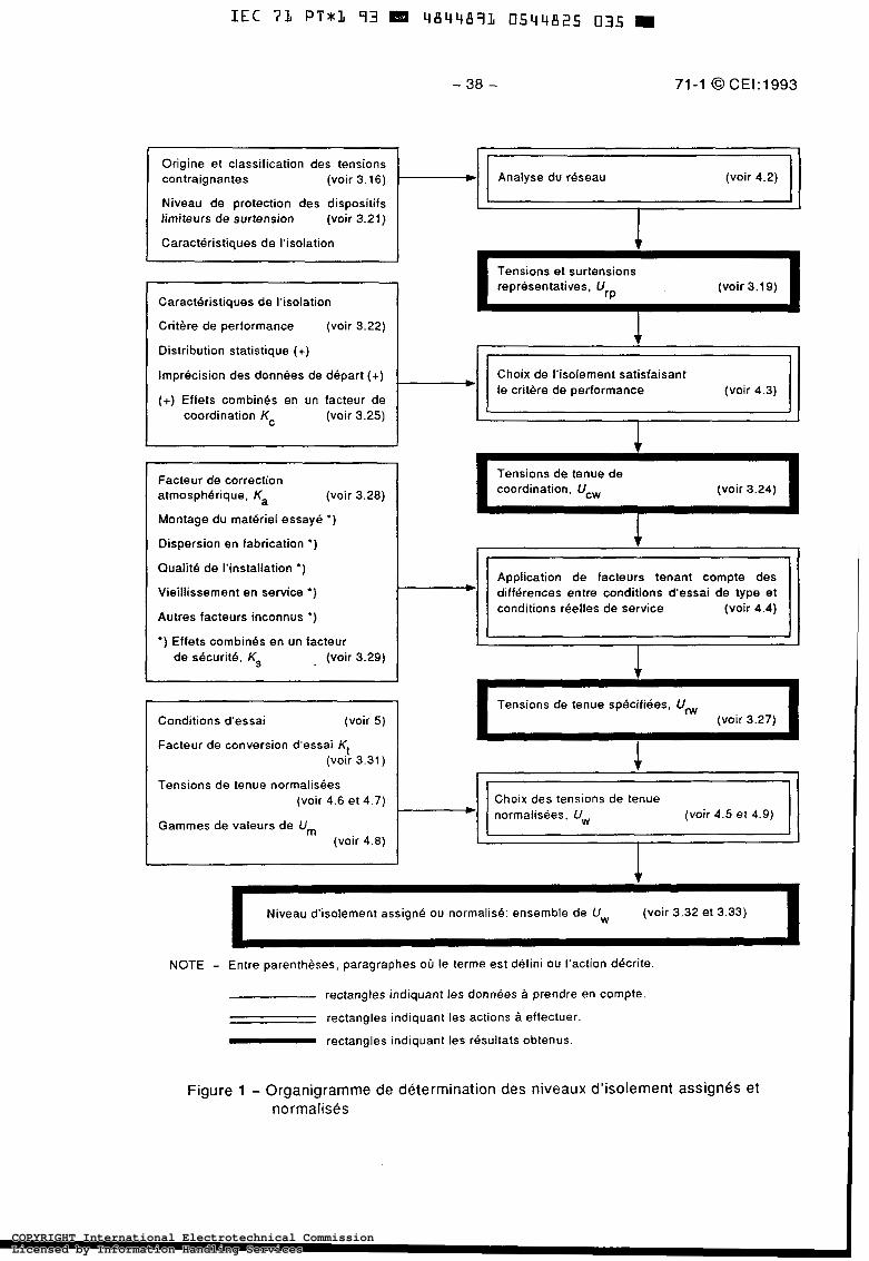
- 38 - 71-1 O CEI:1993
Origine et classification des tensions contraignantes (voir 3.16) Analyse du réseau (voir 4.2)
Niveau de protection des dispositifs limiteurs de surtension (voir 3.21)
Caracteristiques de l'isolation
Critère de performance (voir 3.22)
Distribution statistique (+)
Imprécision des données de départ (+) Choix de l'isolement satisfaisant
(+) Effets combines en un facteur de coordination Kc (voir 3.25)
le critbre de performance (voir 4.3)
I Facteur de correction atmosphérique, Ka (voir 3.28)
Montage du materiel essayé *)
Dispersion en fabrication * )
Oualite de l'installation *)
Vieillissement en service *)
Autres facteurs inconnus *)
*) Effets combines en un facteur de s6curité. Ks (voir 3.29)
Tensions de tenue de coordination, Ucw (voir 3.24)
Application de facteurs tenant compte des différences entre conditions d'essai de type et conditions reelles de service (voir 4.4)
I I I
Tensions de tenue sp6cifiées. Uw Conditions d'essai (voir 5 )
Facteur de conversion d'essai Kt
(voir 3.27)
(voir 3.31 ) 1 Tensions de tenue normalisées
(voir 4.6 et 4.7) Choix des tensions de tenue normalisées. U,,, (voir 4.5 et 4.9)
Gammes de valeurs de Um (voir 4.8)
Niveau d'isolement assigné OU normalisé: ensemble de U, (voir 3.32 et 3.33) I NOTE - Entre parenthèses, paragraphes où le terme est défini ou l'action decrite.
rectangles indiquant les données à prendre en compte
rectangles indiquant les actions à effectuer - rectangles indiquant les résultats obtenus.
Figure 1 - Organigramme de détermination des niveaux d'isolement assignes et normalisés
COPYRIGHT International Electrotechnical CommissionLicensed by Information Handling ServicesCOPYRIGHT International Electrotechnical CommissionLicensed by Information Handling Services
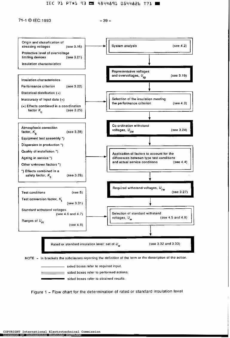
I E C 71 P T * 1 9 3 4 8 4 4 8 9 1 0544826 T 7 1
71-1 O IEC:1993
I I
- 39 -
I . 1
(see 4.2) I I Protective level of overvoltage limiting devices (see 3.21)
I Insulation characteristics I Insulation characteristics
Performance criterion (see 3.22)
Representative voltages and overvoltages, U (see 3.19)
I factor Kc (see 3.25) b b l Statistical distribution (+)
Inaccuracy of input data (+)
(+) Effects combined in a coordination
Selection of the insulation meeting the performance criterion
Atmospheric correction factor, Ka (see 3.28)
Equipment test assembly *)
Dispersion in production * )
Quality of installation *)
Ageing in service *)
Other unknown factors *)
*) Effects combined in a safety factor, Ks (see 3.29)
I Co-ordination withstand voltages, Ucw (see 3.24) I
1 I I I I
Application of factors to account for the differences between type test conditions and actual service conditions (see 4.4) I l -I I
I I I 1 J
Required withstand voltages, Ur, Test conditions (see 5 )
Test conversion factor, Kt (see 3.31)
Standard withstand voltages (see 4.6 and 4.7) Selection of standard withstand
(see 4.5 and 4.9) Ranges of Um
(see 4.8) I I 1
Rated or standard insulation level: set of Uw (see 3.32 and 3.33)
NOTE - In brackets the subclauses reporting the definition of the term or the description of the action
sided boxes refer to required input.
sided boxes refer to performed actions.
sided boxes refer to obtained results.
Figure 1 - Flow chart for the determination of rated or standard insulation level
COPYRIGHT International Electrotechnical CommissionLicensed by Information Handling ServicesCOPYRIGHT International Electrotechnical CommissionLicensed by Information Handling Services
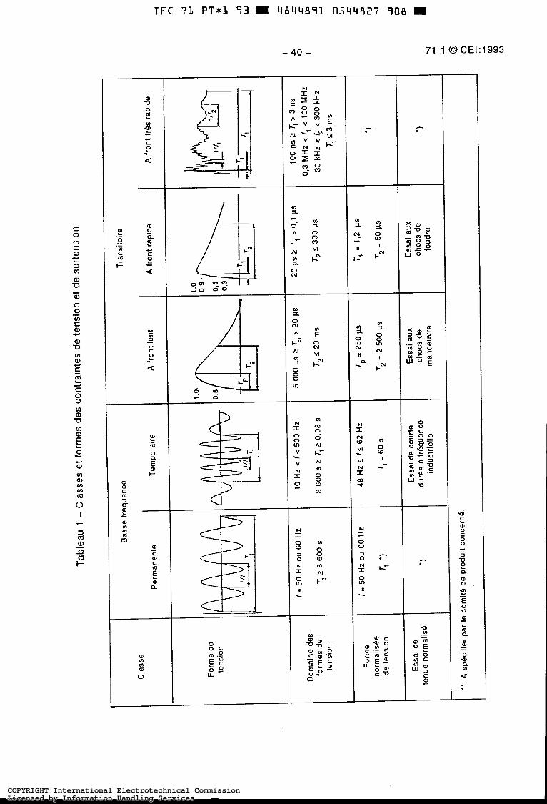
.- E! 2 O a E I-
al o c m 3 0- T - c
I al c m - c m E a al
- 40 -
S O o 3 - o .
N
2 c- O UJ
71-1 0 CEI:1993
COPYRIGHT International Electrotechnical CommissionLicensed by Information Handling ServicesCOPYRIGHT International Electrotechnical CommissionLicensed by Information Handling Services
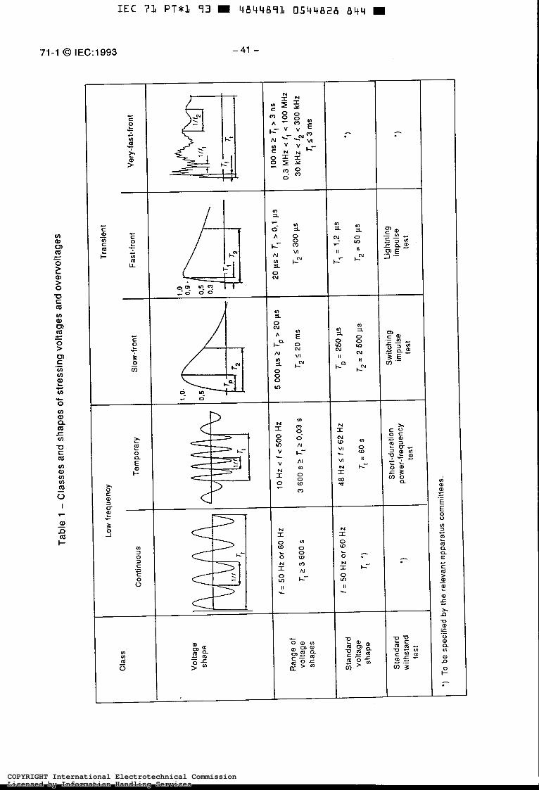
'71-1 O IEC:1993
1
-41 -
I
9 % . - o
O O O (D
COPYRIGHT International Electrotechnical CommissionLicensed by Information Handling ServicesCOPYRIGHT International Electrotechnical CommissionLicensed by Information Handling Services
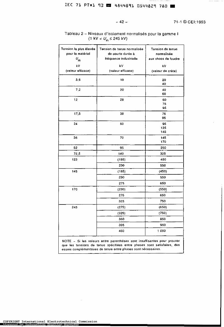
- 42 - 71-1 O CEI:1993
Tableau 2 - Niveaux d'isolement normalisks pour la gamme I (1 kV < U, 2 245 kv)
Tension la plus OlevOe pour le materiel
um kV
(valeur efficace)
3.6
7.2
12
17.5
24
36
52
72.5
123
145
170
245
Tension de tenue normalisée Tension de tenue de courte durée B normatisee
fréquence industrielle
(valeur de crête) (valeur efficace)
kV kV
aux chocs de foudre
10
40 20
40 20
60
28 60 75 95
38 75 95
50 95 125 145
70 145 170
95 250
140 325
(185) 450
230 550
( 185) (450) 230
650 275
550
(230) (550)
275
325
650
750
(275)
(750) (325)
(650)
360
7 050 460
950 395
850
NOTE - Si les valeurs entre parenthèses sont insuffisantes pour prouver que les tensions de tenue spécifiées entre phases sont satisfaites, des essais complémentaires de tenue entre phases sont nécessaires.
COPYRIGHT International Electrotechnical CommissionLicensed by Information Handling ServicesCOPYRIGHT International Electrotechnical CommissionLicensed by Information Handling Services

IEC 71 PT*L 93 m 4844873 0544830 4 T 2 m
71-1 O IEC:1993 - 43 -
Table 2 - Standard insulation levels for range I (1 kV < Um I 245 kv)
Highest voltage Standard short-duration Standard for equipment power-frequency lightning impulse
withstand voltage withstand voltage "m
kV I kV I kV (r.m.s. value) I (r.m.s. value) I (peak value)
3,6 10 20 40
40 60
7.2 20
12 28 60 75 95
173 38 75 95
24 50 95 125 145
36 70 145 1 70
52 95 250
72.5 140 325
123 (185) 450
230 550
145 (185) (450)
230 550
275 650
170 (230) (550)
275 650
325 750
245 (275) (650)
(325) (750) 360 850
395 950
4 60 1 050
NOTE - If values in brackets are considered insufficient to prove that the required phase-to-phase withstand voltages are met, additional phase-to- phase withstand tests are needed.
COPYRIGHT International Electrotechnical CommissionLicensed by Information Handling ServicesCOPYRIGHT International Electrotechnical CommissionLicensed by Information Handling Services
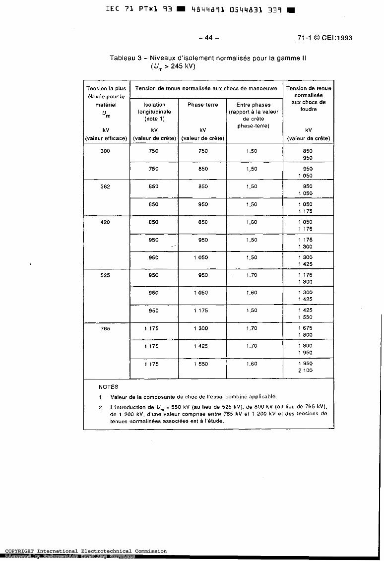
Tableau 3 - Niveaux d'isolement normalis& pour la gamme II (Um > 245 kv)
rension la plus élevbe pour le
matériel
'm
kV valeur efficace)
300
362
420
525
765
Tension de tenue normalisbe aux chocs de manoeuvre Tension de tenue normalis&
aux chocs de foudre
Isolation
de crête (note 1) (rapportà la valeur longitudinale
Entre phases Phase-terre
kV kV phase-terre)
kV
(valeur de crête) (valeur de crbte) (valeur de crête)
750 1 750 1 1.50 850 1 950
750
1 175 1 050 1,60 850 850
1 175 1 050 1.50 950 850
1 050 950 1.50 850 850
1 050 950 1 3 0 850
950
1 300 1 175 1,70 950 950
1 425 1 300 1 S O 1 050 950
1 300 1 175 1.50 950
~~ ~ ~
950
2 100 1 175 1 550 1.60 1 950
1 950 1 175 1 425 1.70 1 800
1 800 1 175 1 300 1.70 1 675
1 550 1 425 1.50 1 175 950
1 425 1 300 1.60 1 050
NOTES
1 Valeur de la composante de choc de l'essai combiné applicable
2 L'introduction de U,,, = 550 kV (au lieu de 525 kv), de 800 kV (au lieu de 765 kv). de 1 200 kv, d'une valeur comprise entre 765 kV et 1 200 kV et des tensions de tenues normalisées associées est à I'étude.
COPYRIGHT International Electrotechnical CommissionLicensed by Information Handling ServicesCOPYRIGHT International Electrotechnical CommissionLicensed by Information Handling Services
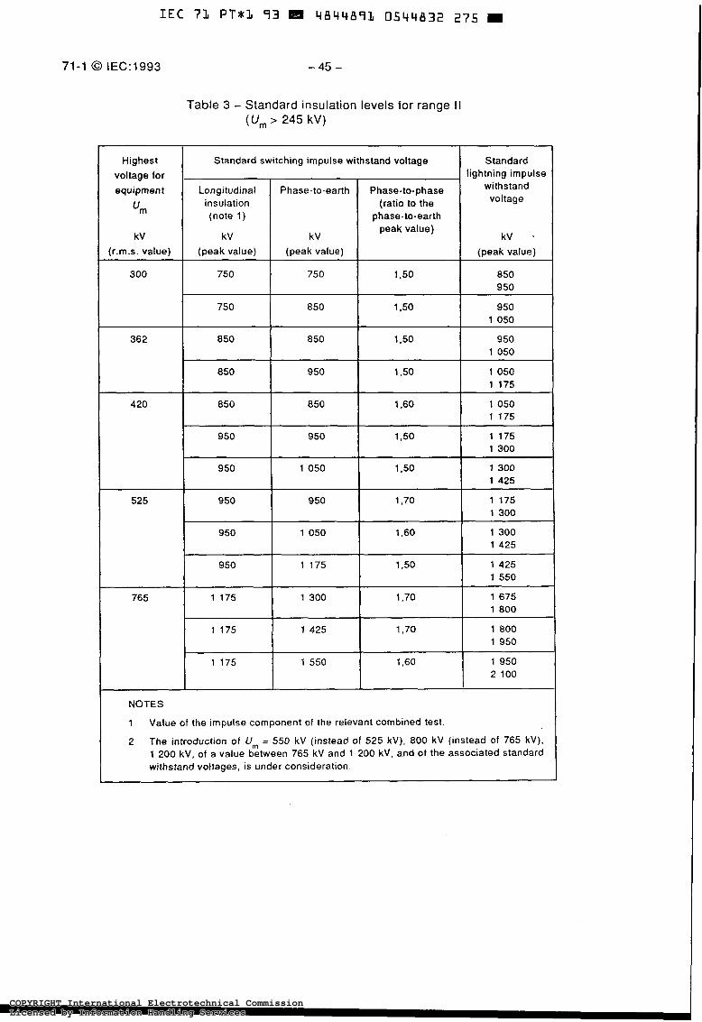
I E C 7 1 P T * % 73 m 4 8 4 4 8 9 3 0544832 275
71-1 O IEC:1993 -45 -
Table 3 - Standard insulation levels for range I I (U, 245 kv)
Highest I Standard switching impulse withstand voltage I Standard voltage for equipment
lightning impulse withstand
insulation (ratio to the (note 1) phase-to-earth
peak value)
'm
kV
voltage
kV *
(r.m.s. value)
300
420
(peak value)
750
750
850
(peak value)
750
850
850
(peak value) I
1.50 1 850 950
~~ ~~
1 3 0 1 O50
950
1.50 ~ ~ [ 950 1 050
I I I I 1 175
950
1.60 1 O50 1 1 175
950 I 1,50 1 175 I 1 300 1 950 I 1 O50 I 1,50 I 1 300 1 425
525 I 950 1 950 1 1.70 1 1 175 1 300
I 950 I 050 I 1,60 1 300 I 1 425
I I 175 I 1.50 1 425 1 1 550 ~ ~~ ~~
765 1 800 1 675 1,70 1 300 1 175
1 175 1 800 1.70 1 425
2 100 1 950 1.60 1 550 1 175
1 950
NOTES
1 Value of the impulse component of the relevant combined test.
2 The introduction of U, = 550 kV (instead of 525 kv), 800 kV (instead of 765 kv), 1 200 kv, of a value between 765 kV and 1 200 kv , and of the associated standard withstand voltages. is under consideration.
COPYRIGHT International Electrotechnical CommissionLicensed by Information Handling ServicesCOPYRIGHT International Electrotechnical CommissionLicensed by Information Handling Services

- 46 - 71 -1 O CE1 1 1 993
Annexe A (informative)
Tableau A . l - Valeurs de niveaux d'isolement assignes pour 1 kV U,,, I 245 kV pour des tensions les plus BlevBes pour le matBrie1 U,,, non normalisees par la CEI, basees sur la pratique existant dans certains pays
Tension la plus blevbe normalisbe de courte duree à pour le materiel
Tension de tenue Tension de tenue normalis6-e
"m frbquence industrielle aux chocs de foudre
kV
(valeur de crdte) (valeur efficace) (valeur efficace)
kV kV
2.75 30 15 45 60
5.5 45 19 60 75
8,25 27 60 75 95
15,5 35 75 85
I10
I I I I
COPYRIGHT International Electrotechnical CommissionLicensed by Information Handling ServicesCOPYRIGHT International Electrotechnical CommissionLicensed by Information Handling Services
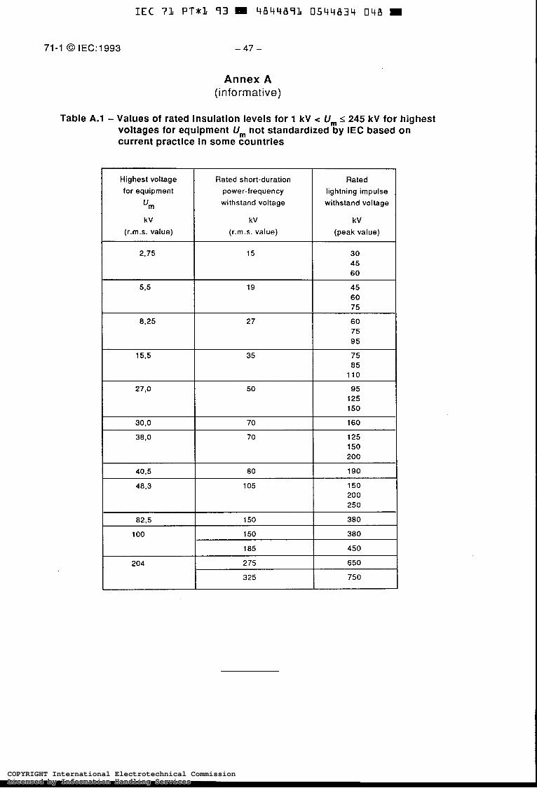
71-1 O IEC:1993
IEC 71 P T * & 73 4844873 0544834 048
-47-
Annex A (informative)
Table A.l - Values of rated insulation levels for 1 kV U,,, 5 245 kV for highest voltages for equipment U, not standardized by IEC based on current practice in some countries
Highest voltage for equipment
"m
kV (r.m.s. value)
Rated short-duration Rated
power-frequency
(peak value) (r.m.s. value)
kV kV
withstand voltage withstand voltage lightning impulse
30 45 60
45 60 75
27.0 50 95 125 150
~
30,O 160 70
38,O 70 150 125
200
40.5 80 190
48,3 105 150 200 250
~~ ~~~~~ ~
82.5
1 O0
380 150
650 2 75 204
450 185
380 150
325 750
COPYRIGHT International Electrotechnical CommissionLicensed by Information Handling ServicesCOPYRIGHT International Electrotechnical CommissionLicensed by Information Handling Services
IEC Ï’L PT*L 93 4844891 0544835 T84
Publications de la CE1 préparées par le Comité d’Etudes no 28
71: - Coordination de l’isolement. 71-1 (1993) Pattie 1: Défmitions, principes et règles. 71-2 (1976) Deuxième partie: Guide d’application. 72-3 (1982) Troisième partie: Coordination de l’isolement entre
p h a s e s . Principes, règles et guide d’application. 661: - Coordination de l’isolement des matériels dans les systèmes
(réseaux) à basse tension. 664-1 (1992) Partie 1: Principes, prescriptions et essais. 664-3 (1992) Partie 3: Utilisation de revêtements pour réaliser la
amdination de l’isolement des cartes imprimés équipks.
IEC publications prepared by Technical Committee No. 28
71: -Insulation oo-ordination. 71-1 (1993) Part 1: Definitions, principles and rules. 71-2 (1976) Part 2 Application guide. 71-3 (1982) Part 3: Phase-tephase insulation Co-ordination.
Principles. rules and application guide. 664: - Insulation coordination for equipment within low-voltage
systems. 664-1 (1992) Part 1: Principles, requirements and tests.
664-3 (1992) Part 3: Use of coatings to achieve insulation coordination of printed board assemblies.
Publication 7 1 - I
COPYRIGHT International Electrotechnical CommissionLicensed by Information Handling ServicesCOPYRIGHT International Electrotechnical CommissionLicensed by Information Handling Services
I E C 7 1 P T * 1 93 MW 4 8 4 4 8 9 1 0 5 4 4 8 3 6 910 m
T y p e s a and printsd by the IEC Central Office GENEVA. SWITZERLAND
COPYRIGHT International Electrotechnical CommissionLicensed by Information Handling ServicesCOPYRIGHT International Electrotechnical CommissionLicensed by Information Handling Services
![inDEx [ ] · PDF fileCEi En50347 iEC 60072-1 iEC 60072-2 The coupling dimensions are in compliance with the following standards: unEL 13113-71 for the B3 mounting and for other frame](https://static.fdocuments.us/doc/165x107/5a9f52a87f8b9a71178c9dee/index-en50347-iec-60072-1-iec-60072-2-the-coupling-dimensions-are-in-compliance.jpg)


![European Commission Seventh Framework …...(RAMS)”, CENELEC 1999 [2] COMITÉ EUROPÉEN DE NORMALISATION ÉLECTROTECHNIQUE: “CLC/TR 50126-2 Railway applications – The specification](https://static.fdocuments.us/doc/165x107/5fdea2f747097a1203410493/european-commission-seventh-framework-ramsa-cenelec-1999-2-comit-europen.jpg)


