Technical Specification for an Overhead Line Real …...purchase of the Overhead Line (OHL)...
24
Document Reference: CLNR-L149 Version: 1.0 Date of Issue: December 2014 1 Copyright Northern Powergrid (Northeast) Limited, Northern Powergrid (Yorkshire) Plc, 2014 Technical recommendation for the purchase of overhead line Real Time Thermal Rating systems 1 Purpose The purpose of this document is to set out and describe the technical requirements developed, that enabled the purchase of the Overhead Line (OHL) Real-time Thermal Rating (RTTR) System applied on the Northern Powergrid High and Extra High Voltage power distribution networks that were trialled on the Customer-Led Network Revolution project. 2 Scope This recommendation details the technical requirements for all equipment to be used in the calculation of OHL RTTR; including line-mounted sensors, remote weather stations and computing equipment (that may be located in primary or secondary sub-stations, remote servers or control rooms). The document applies to RTTR equipment at operating voltages: High Voltage (>1000V, < 22kV as specified in ENA ER 43-3); Extra High Voltage (≥ 22kV, < 132kV as specified in ENA ER 43-3); This recommendation includes the interfacing requirements with a remote server. A summary table of the supplier/product technical compliance is given in Appendix 1 & 2 for manufacturers to complete, detailing any variation. Manufacturers are encouraged to offer more than one option if they have a number of possible solutions. The technical requirements detailed in the main body of this document are generic. Additional site specific data will be discussed with the potential supplier.
Transcript of Technical Specification for an Overhead Line Real …...purchase of the Overhead Line (OHL)...
Document Reference: CLNR-L149
Version: 1.0 Date of Issue: December 2014 1
Copyright Northern Powergrid (Northeast) Limited, Northern Powergrid (Yorkshire) Plc, 2014
Technical recommendation for the purchase of overhead line Real Time Thermal Rating systems
1 Purpose The purpose of this document is to set out and describe the technical requirements developed, that enabled the
purchase of the Overhead Line (OHL) Real-time Thermal Rating (RTTR) System applied on the Northern
Powergrid High and Extra High Voltage power distribution networks that were trialled on the Customer-Led
Network Revolution project.
2 Scope This recommendation details the technical requirements for all equipment to be used in the calculation of OHL
RTTR; including line-mounted sensors, remote weather stations and computing equipment (that may be
located in primary or secondary sub-stations, remote servers or control rooms).
The document applies to RTTR equipment at operating voltages:
High Voltage (>1000V, < 22kV as specified in ENA ER 43-3);
Extra High Voltage (≥ 22kV, < 132kV as specified in ENA ER 43-3);
This recommendation includes the interfacing requirements with a remote server. A summary table of the
supplier/product technical compliance is given in Appendix 1 & 2 for manufacturers to complete, detailing any
variation.
Manufacturers are encouraged to offer more than one option if they have a number of possible solutions. The
technical requirements detailed in the main body of this document are generic. Additional site specific data will
be discussed with the potential supplier.

Document Reference: CLNR-L149
Version: 1.0 Date of Issue: December 2014 2
Copyright Northern Powergrid (Northeast) Limited, Northern Powergrid (Yorkshire) Plc, 2014
Contents
1 Purpose ................................................................................................................................................1
2 Scope ...................................................................................................................................................1
2.1 Contents.........................................................................................................................................2
3 Technical Requirements ....................................................................................................................3
3.1 General ..........................................................................................................................................3
3.2 Equipment Mounting ......................................................................................................................4
3.3 Equipment Specification ................................................................................................................4
3.4 RTTR Model...................................................................................................................................5
3.5 Weather Measurement Device Outputs ........................................................................................7
3.6 Communication between System Components.............................................................................7
3.7 Safety .............................................................................................................................................8
4 References ...........................................................................................................................................9
4.1 External Documentation ................................................................................................................9
5 Definitions ......................................................................................................................................... 10
Appendix 1 – Schedule of Suppliers Technical Data ............................................................................ 11
Appendix 2 – Self Certification Conformance Declaration................................................................... 15
Appendix 3 – Addendum to Supplier Requirements ............................................................................ 18
Appendix 4 - Pre-commission testing, Routine Inspection and Maintenance requirements ........... 19
Appendix 5 - Technical Information Check List .................................................................................... 20
Appendix 6 – Schedule of Components ................................................................................................. 21
Appendix 7 – Electromagnetic Compatibility ........................................................................................ 22

Document Reference: CLNR-L149
Version: 1.0 Date of Issue: December 2014 3
Copyright Northern Powergrid (Northeast) Limited, Northern Powergrid (Yorkshire) Plc, 2014
3 Technical Requirements
3.1 General
The constituent components of an OHL RTTR system are:
On-line measurement devices
Local controllers
Weather stations
Communications hubs
RTTR calculation engines
Single weather stations and RTTR calculation engines should be capable of being used to support multiple sites.
All equipment intended for outdoor installation shall be environmentally tested to IP55 and all internal equipment to IP52 in accordance with BSEN 60529. All equipment should be capable of operating under conditions of shock and vibration normally encountered in service on UK distribution networks. The dimensions of all equipment should be specified by the suppliers. All equipment with a real-time clock should be capable of synchronisation with an Internet Engineering Task Force (IETF) standard Network Time Protocol version 4 (NTPv4) server.
3.1.1 On-line Measurement Devices
It must be feasible to install line-mounted equipment using approved live-line procedures at voltage levels where live-line working is permitted by DNO safety rules. Higher voltage levels will require an outage to install, but installation should be such that ladder access from towers is sufficient and scaffolding is not required.
The device shall have a backup battery, rechargeable from scavenged or renewable sources, and capable of providing no less than 48 hours backup power. The time to fully charge the battery shall be no more than 24 hours. The power source(s) adopted shall be sufficient and suitable to ensure that the battery is kept charged at all times under weather and loading conditions expected in the UK.
The device shall have sufficient on-board non-volatile storage for at least 40 minutes of readings at the maximum operating rate.
3.1.2 Weather Measurement Devices
If anemometers are used to record weather data whilst attached to poles or towers they shall be the electronic type mounted from the side of the structure with prevailing wind so as to avoid wind shading. The preferred distance from the pole shall be 10 pole diameters (where practicable).
3.1.3 Local Controller
The local controller shall have a backup battery, rechargeable from local renewable sources, and capable of providing no less than 48 hours of backup power. The time to fully charge the battery shall be no more than 8 hours.

Document Reference: CLNR-L149
Version: 1.0 Date of Issue: December 2014 4
Copyright Northern Powergrid (Northeast) Limited, Northern Powergrid (Yorkshire) Plc, 2014
3.2 Equipment Mounting
3.2.1 Line-Mounted Equipment
Equipment should be designed for attachment directly onto the overhead line conductors. Devices should be suitable for application onto conductors with conductor cross-section area ranging between 16mm
2 and
500mm2 depending on the specific line being rated. Further information should be sought on the specific line
construction, although flexibility in this regard would be very desirable.
Suppliers should provide details confirming that no corrosion issues will be created due to large variances in the electro-chemical series of the conductor and any metallic components within the installed device that have direct contact with the conductor.
3.2.2 Pole, Tower or Remote – Mounted Equipment
The equipment should be designed for permanent attachment to an appropriate wood pole through the use of M12 or M16 galvanized coach screws or mounted on steel towers. Where fixture is required to towers, this should be achieved through the use of bolted brackets or clamps that fit around existing steel members. Under no circumstances should the fixing require drilling of any tower members.
3.2.3 Substation Equipment
Where appropriate, equipment may be located in a substation. A standard 19” rack shall be used for housing the equipment in this case.
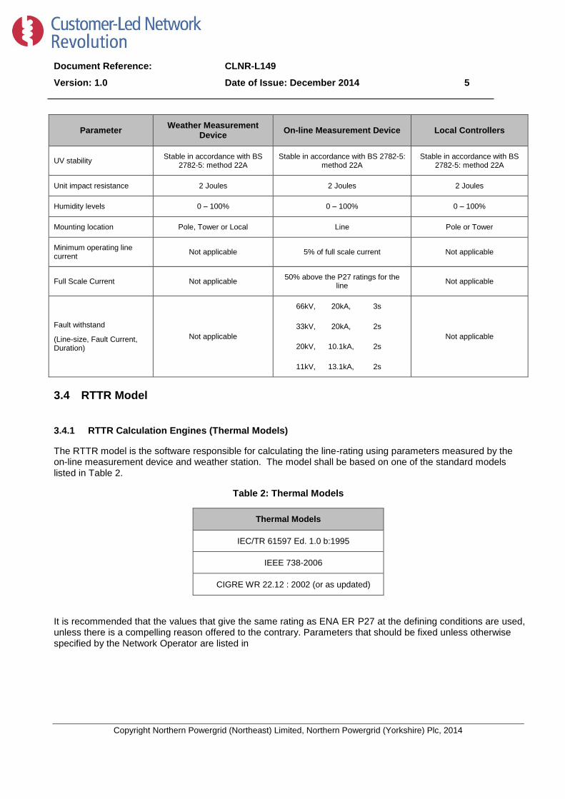
3.3 Equipment Specification
Table 1: Device technical specifications
Parameter Weather Measurement
Device On-line Measurement Device Local Controllers
Power supply From Local Controller Line current scavenge with battery
backup Solar Power with battery
backup
Backup battery endurance N/A 48 hours 48 hours
Backup battery re-charge time
N/A 24 hours 8 hours
Operating temperature -20°C to 40°C -20°C to 80°C -20°C to 40°C
Maintenance Annually > 3 years > 3 years
Lifetime >10 years >10 years >10 years
Maximum weight 25kg 8kg 25kg
Sampling rate 5 minute capability(user
configurable) 5 minute capability (user
configurable) 5 minute capability(user
configurable)
Operating voltage ≤50V AC
≤120V DC 0 to 220kV
≤50V AC
≤120V DC
Document Reference: CLNR-L149
Version: 1.0 Date of Issue: December 2014 5
Copyright Northern Powergrid (Northeast) Limited, Northern Powergrid (Yorkshire) Plc, 2014
Parameter Weather Measurement
Device On-line Measurement Device Local Controllers
UV stability Stable in accordance with BS
2782-5: method 22A Stable in accordance with BS 2782-5:
method 22A Stable in accordance with BS
2782-5: method 22A
Unit impact resistance 2 Joules 2 Joules 2 Joules
Humidity levels 0 – 100% 0 – 100% 0 – 100%
Mounting location Pole, Tower or Local Line Pole or Tower
Minimum operating line current
Not applicable 5% of full scale current Not applicable
Full Scale Current Not applicable 50% above the P27 ratings for the
line Not applicable
Fault withstand
(Line-size, Fault Current, Duration)
Not applicable
66kV, 20kA, 3s
33kV, 20kA, 2s
20kV, 10.1kA, 2s
11kV, 13.1kA, 2s
Not applicable
3.4 RTTR Model
3.4.1 RTTR Calculation Engines (Thermal Models)
The RTTR model is the software responsible for calculating the line-rating using parameters measured by the on-line measurement device and weather station. The model shall be based on one of the standard models listed in Table 2.
Table 2: Thermal Models
Thermal Models
IEC/TR 61597 Ed. 1.0 b:1995
IEEE 738-2006
CIGRE WR 22.12 : 2002 (or as updated)
It is recommended that the values that give the same rating as ENA ER P27 at the defining conditions are used, unless there is a compelling reason offered to the contrary. Parameters that should be fixed unless otherwise specified by the Network Operator are listed in

Document Reference: CLNR-L149
Version: 1.0 Date of Issue: December 2014 6
Copyright Northern Powergrid (Northeast) Limited, Northern Powergrid (Yorkshire) Plc, 2014
Table 3. It should be noted that absorptivity and emissivity will change with ageing assets for example; new Aluminium conductors have absorptivity of the order of 0.2 to 0.3. Old aluminium conductors have an absorptivity which approaches 0.9.

Document Reference: CLNR-L149
Version: 1.0 Date of Issue: December 2014 7
Copyright Northern Powergrid (Northeast) Limited, Northern Powergrid (Yorkshire) Plc, 2014
Table 3: Fixed Parameters
Fixed Parameters
Yaw Angle 12°
Corona heating 0
Evaporative cooling 0
Magnetic Heating 0
Solar gain 0
Absorptivity of conductor 0.9
Emissivity of conductor 0.8
Radial conductivity 4 W / m.K
Parameters used in the thermal models that depend upon the characteristics of the equipment from which measurements are taken will vary. These parameters are listed in Table 4 and shall be specified at each installation location. Other parameters for use within the model should be calculated or measured directly.
Table 4: Site Dependent Parameters
Parameters
Conductor Type and Size
Conductor Resistance @ 20°C per unit length
Temperature coefficient of resistance for conductor
Pole/Tower span and height above terrain
Minimum electrical clearance and conductor temperature at time of installation
Standard(s) that the line is designed to (e.g. design temperature, minimum clearance).
3.4.2 Weather Interpolation and Controlled Degradation
It is desirable that the calculation engine should be able to predict line temperature (and hence) ratings between weather measurement sites, both to reduce the number of weather measurement sites installed, and to enable the system to continue to operate (albeit with degraded accuracy) when one or more weather stations are not working. If offered, suppliers should provide practical trial evidence of their system’s efficacy and accuracy in performing such interpolation.

Document Reference: CLNR-L149
Version: 1.0 Date of Issue: December 2014 8
Copyright Northern Powergrid (Northeast) Limited, Northern Powergrid (Yorkshire) Plc, 2014
3.4.3 RTTR Model Outputs
A list of the outputs that the system should be able to send to a remote point is given in Table 5; these may be calculated or measured directly. All output parameters should be time-stamped with an accuracy of ±5 seconds and a precision of ±1 second. All time parameters are to be accepted and output in UTC. An option to convert to configurable local time zones for user interaction may be provided. Where additional outputs are available these should be specified by manufacturers. Health indicators should be provided. RTTR settings should be configurable, including:-
Changes in network configurations, for example a normally open-point is closed;
Changes in maximum and minimum ratings, types of component;
Change of settings – manufacturers should list the settings that are configurable.
Table 5: RTTR model outputs
Accuracy Precision Range Other
Ampacity Defined 1 A 0 → Max Rating Average over 5 min.
Conductor Current ±1% 1 A 0 → 150% of the P27 ratings for
the line Average over 5 min.
Conductor Temperature ±2 °C 1 °C -20 °C to 80 °C Average over 5 min.
Health Indicator NA NA NA Heartbeat/Handshake
3.5 Weather Measurement Device Outputs
The weather measurement device should provide the data listed in Table 6. The specification should be for an electronic anemometer which can cater for low wind speed and have device reliability. The device must be capable of measuring low wind speeds (between 0.05 and 0.5 m/s) accurately otherwise the ratings during low wind speeds will be unnecessarily pessimistic, restricting capacity and increasing call on load management systems. Where additional outputs are available these should be specified by manufacturers.
Table 6: Weather measurement device output
Accuracy Precision Range Other
Ambient temperature ±1°C 0.1°C -20°C to 50°C Average over 5 min.
Wind Speed ±0.1 m/s 0.1 m/s 0-60 m/s Average over 5 min.
Wind direction ±2° 1° 0 - 359° N Average over 5 min.
3.6 Communication between System Components
All systems should be suitable to communicate with industry standard SCADA protocols; this should be via direct communication or by using an intermediate device. The preferred protocols are likely to be DNP3 or IEC 61850. In all cases the communications equipment must be compliant with the EMC requirements given in Appendix 7. The manufacturer will be required to agree the communications protocol and format of data with the purchasing Network Operator. For applications considering 3G and GPRS communications, roaming SIM card compliance is required.
Document Reference: CLNR-L149
Version: 1.0 Date of Issue: December 2014 9
Copyright Northern Powergrid (Northeast) Limited, Northern Powergrid (Yorkshire) Plc, 2014
3.7 Safety
Live line working is permitted on UK Distribution Networks, typically up to 33kV although limits do vary. This is
subject to suitable working practices being developed and the appropriate health and safety policies. Potential
suppliers should comply with their statutory obligations under the Construction (Design and Management)
Regulations 2007, in particular to avoid foreseeable risks to those involved in the installation and further use of
the equipment. A list of appropriate BS, ENA standards and guidelines are given at the end of this document;
these should be adhered and conformed to. Manufacturers should provide example procedures, method
statements and risk assessments to the Network Operator to facilitate the assessment of safe installation
procedures, for both live and dead installations.
Document Reference: CLNR-L149
Version: 1.0 Date of Issue: December 2014 10
Copyright Northern Powergrid (Northeast) Limited, Northern Powergrid (Yorkshire) Plc, 2014
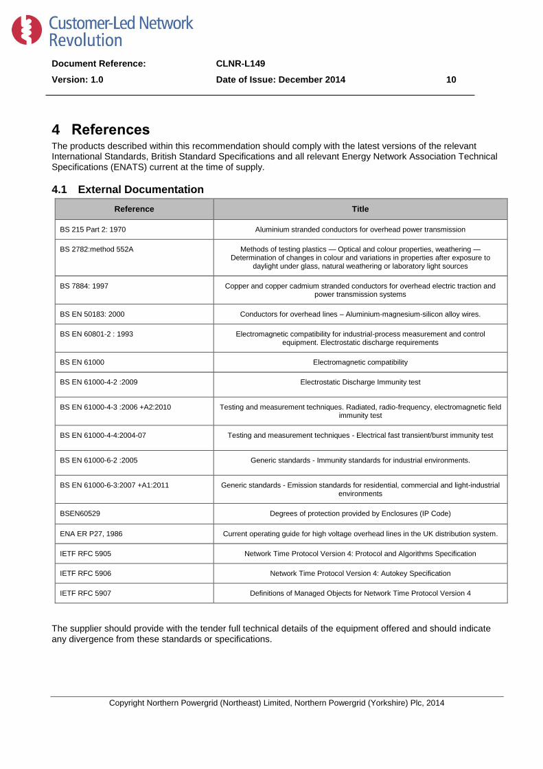
4 References The products described within this recommendation should comply with the latest versions of the relevant International Standards, British Standard Specifications and all relevant Energy Network Association Technical Specifications (ENATS) current at the time of supply.
4.1 External Documentation
Reference Title
BS 215 Part 2: 1970 Aluminium stranded conductors for overhead power transmission
BS 2782:method 552A Methods of testing plastics — Optical and colour properties, weathering — Determination of changes in colour and variations in properties after exposure to
daylight under glass, natural weathering or laboratory light sources
BS 7884: 1997 Copper and copper cadmium stranded conductors for overhead electric traction and power transmission systems
BS EN 50183: 2000 Conductors for overhead lines – Aluminium-magnesium-silicon alloy wires.
BS EN 60801-2 : 1993 Electromagnetic compatibility for industrial-process measurement and control equipment. Electrostatic discharge requirements
BS EN 61000 Electromagnetic compatibility
BS EN 61000-4-2 :2009 Electrostatic Discharge Immunity test
BS EN 61000-4-3 :2006 +A2:2010 Testing and measurement techniques. Radiated, radio-frequency, electromagnetic field immunity test
BS EN 61000-4-4:2004-07 Testing and measurement techniques - Electrical fast transient/burst immunity test
BS EN 61000-6-2 :2005 Generic standards - Immunity standards for industrial environments.
BS EN 61000-6-3:2007 +A1:2011 Generic standards - Emission standards for residential, commercial and light-industrial environments
BSEN60529 Degrees of protection provided by Enclosures (IP Code)
ENA ER P27, 1986 Current operating guide for high voltage overhead lines in the UK distribution system.
IETF RFC 5905 Network Time Protocol Version 4: Protocol and Algorithms Specification
IETF RFC 5906 Network Time Protocol Version 4: Autokey Specification
IETF RFC 5907 Definitions of Managed Objects for Network Time Protocol Version 4
The supplier should provide with the tender full technical details of the equipment offered and should indicate any divergence from these standards or specifications.
Document Reference: CLNR-L149
Version: 1.0 Date of Issue: December 2014 11
Copyright Northern Powergrid (Northeast) Limited, Northern Powergrid (Yorkshire) Plc, 2014
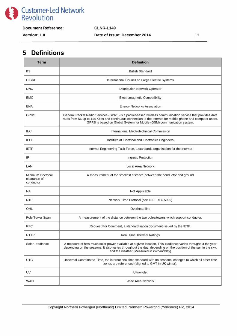
5 Definitions
Term Definition
BS British Standard
CIGRE International Council on Large Electric Systems
DNO Distribution Network Operator
EMC Electromagnetic Compatibility
ENA Energy Networks Association
GPRS General Packet Radio Services (GPRS) is a packet-based wireless communication service that provides data rates from 56 up to 114 Kbps and continuous connection to the Internet for mobile phone and computer users.
GPRS is based on Global System for Mobile (GSM) communication system.
IEC International Electrotechnical Commission
IEEE Institute of Electrical and Electronics Engineers
IETF Internet Engineering Task Force, a standards organisation for the Internet
IP Ingress Protection
LAN Local Area Network
Minimum electrical clearance of conductor
A measurement of the smallest distance between the conductor and ground
NA Not Applicable
NTP Network Time Protocol (see IETF RFC 5905)
OHL Overhead line
Pole/Tower Span A measurement of the distance between the two poles/towers which support conductor.
RFC Request For Comment, a standardisation document issued by the IETF.
RTTR Real Time Thermal Ratings
Solar Irradiance A measure of how much solar power available at a given location. This irradiance varies throughout the year depending on the seasons. It also varies throughout the day, depending on the position of the sun in the sky,
and the weather (Measured in kWh/m2/day)
UTC Universal Coordinated Time, the international time standard with no seasonal changes to which all other time zones are referenced (aligned to GMT in UK winter).
UV Ultraviolet
WAN Wide Area Network

Document Reference: CLNR-L149
Version: 1.0 Date of Issue: December 2014 12
Copyright Northern Powergrid (Northeast) Limited, Northern Powergrid (Yorkshire) Plc, 2014
Appendix 1 – Schedule of Suppliers Technical Data The following Technical schedules must be completed by suppliers
Thermal Models (Table 2)
Thermal Models Conformity with, (Yes / No)
IEC/TR 61597 Ed. 1.0 b:1995
IEEE 738-2006
CIGRE WR 22.12 : 2002
Fixed Parameters (Table 3)
Fixed Parameters Conformity with, Yes / No
If no, please detail value used.
Wind speed < 2m/s Yaw angle to line is set at 12°
Corona heating 0
Evaporative cooling 0
Magnetic Heating 0
Global Solar Radiation 0
Absorptivity of conductor 0.9
Emissivity of conductor 0.8
Radial conductivity 4 W / m.K
Site Dependent Parameters (Table 4)
Parameter Value
Conductor Type and Size
Conductor Resistance @ 20°C per unit length
Temperature coefficient of resistance for conductor
Pole/Tower span and height above terrain
Minimum electrical clearance and conductor temperature at time of installation

Document Reference: CLNR-L149
Version: 1.0 Date of Issue: December 2014 13
Copyright Northern Powergrid (Northeast) Limited, Northern Powergrid (Yorkshire) Plc, 2014
Parameter Value
Standard(s) that the line is designed to (e.g. design temperature, minimum clearance).
RTTR Model Outputs (Table 5)
Accuracy Precision Range Other
Ampacity
Conductor Current
Conductor Temperature
Health Indicator
Weather measurement device output (Table 6)
Accuracy Precision Range Other
Ambient temperature
Wind Speed
Wind direction
Ability to accept expected Inputs
Input Comments
Change of settings - manufacturer should list the settings that are configurable.
Document Reference: CLNR-L149
Version: 1.0 Date of Issue: December 2014 14
Copyright Northern Powergrid (Northeast) Limited, Northern Powergrid (Yorkshire) Plc, 2014
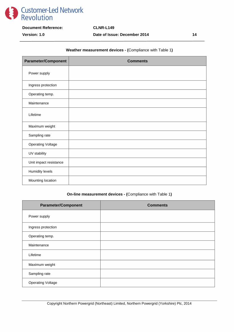
Weather measurement devices - (Compliance with Table 1)
Parameter/Component Comments
Power supply
Ingress protection
Operating temp.
Maintenance
Lifetime
Maximum weight
Sampling rate
Operating Voltage
UV stability
Unit impact resistance
Humidity levels
Mounting location
On-line measurement devices - (Compliance with Table 1)
Parameter/Component Comments
Power supply
Ingress protection
Operating temp.
Maintenance
Lifetime
Maximum weight
Sampling rate
Operating Voltage

Document Reference: CLNR-L149
Version: 1.0 Date of Issue: December 2014 15
Copyright Northern Powergrid (Northeast) Limited, Northern Powergrid (Yorkshire) Plc, 2014
Parameter/Component Comments
UV stability
Unit impact resistance
Humidity levels
Mounting location
Minimum operating current
Maximum operating conductor temperature
Fault withstand
(Fault Current, Duration)
Local controller (Compliance with Table 1)
Parameter/Component Comments
Power supply
Ingress protection
Operating temp.
Maintenance
Lifetime
Maximum weight
Sampling rate
Operating Voltage
UV stability
Unit impact resistance
Humidity levels
Mounting location
Document Reference: CLNR-L149
Version: 1.0 Date of Issue: December 2014 16
Copyright Northern Powergrid (Northeast) Limited, Northern Powergrid (Yorkshire) Plc, 2014
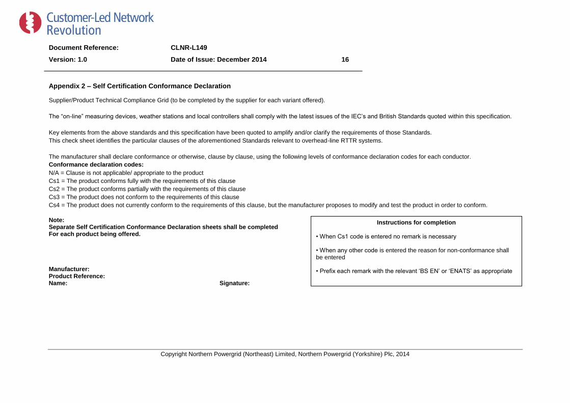
Appendix 2 – Self Certification Conformance Declaration
Supplier/Product Technical Compliance Grid (to be completed by the supplier for each variant offered).
The “on-line” measuring devices, weather stations and local controllers shall comply with the latest issues of the IEC’s and British Standards quoted within this specification.
Key elements from the above standards and this specification have been quoted to amplify and/or clarify the requirements of those Standards.
This check sheet identifies the particular clauses of the aforementioned Standards relevant to overhead-line RTTR systems.
The manufacturer shall declare conformance or otherwise, clause by clause, using the following levels of conformance declaration codes for each conductor.
Conformance declaration codes:
N/A = Clause is not applicable/ appropriate to the product
Cs1 = The product conforms fully with the requirements of this clause
Cs2 = The product conforms partially with the requirements of this clause
Cs3 = The product does not conform to the requirements of this clause
Cs4 = The product does not currently conform to the requirements of this clause, but the manufacturer proposes to modify and test the product in order to conform.
Note: Separate Self Certification Conformance Declaration sheets shall be completed For each product being offered. Manufacturer: Product Reference: Name: Signature: Date:
Instructions for completion
• When Cs1 code is entered no remark is necessary
• When any other code is entered the reason for non-conformance shall be entered
• Prefix each remark with the relevant ‘BS EN’ or ‘ENATS’ as appropriate

Document Reference: CLNR-L149
Version: 1.0 Date of Issue: December 2014 17
Copyright Northern Powergrid (Northeast) Limited, Northern Powergrid (Yorkshire) Plc, 2014
Specific requirements within this specification
Clause/Sub-clause Requirements Conformance Code Remarks
Table 1 Compliance with device technical specifications
Table 2 Compliance with one or more specified thermal model(s)
Table 3 Compliance with fixed parameters
Table 4 Compliance with site dependent parameters
Table 5 Compliance with RTTR model outputs
Table 6 Compliance with wind measurement device outputs
Document Reference: CLNR-L149
Version: 1.0 Date of Issue: December 2014 18
Copyright Northern Powergrid (Northeast) Limited, Northern Powergrid (Yorkshire) Plc, 2014
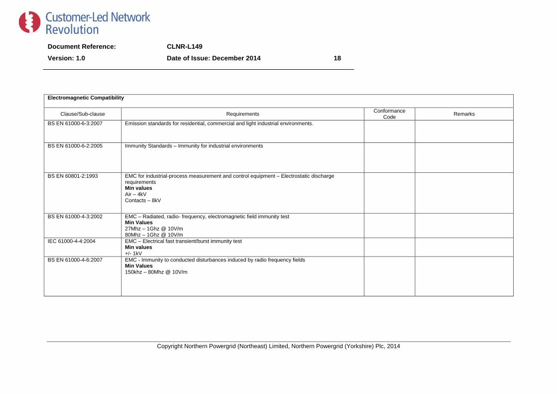
Electromagnetic Compatibility
Clause/Sub-clause Requirements Conformance
Code Remarks
BS EN 61000-6-3:2007
Emission standards for residential, commercial and light industrial environments.
BS EN 61000-6-2:2005 Immunity Standards – Immunity for industrial environments
BS EN 60801-2:1993 EMC for industrial-process measurement and control equipment – Electrostatic discharge requirements Min values Air – 4kV Contacts – 8kV
BS EN 61000-4-3:2002 EMC – Radiated, radio- frequency, electromagnetic field immunity test Min Values 27Mhz – 1Ghz @ 10V/m 80Mhz – 1Ghz @ 10V/m
IEC 61000-4-4:2004 EMC – Electrical fast transient/burst immunity test Min values +/- 1kV
BS EN 61000-4-6:2007 EMC - Immunity to conducted disturbances induced by radio frequency fields Min Values 150khz – 80Mhz @ 10V/m

Document Reference: CLNR-L149
Version: 1.0 Date of Issue: December 2014 19
Copyright Northern Powergrid (Northeast) Limited, Northern Powergrid (Yorkshire) Plc, 2014
Appendix 3 – Addendum to Supplier Requirements
Please indicate Packaging/delivery information
Details of how this product will be packaged and delivered shall be provided.
Please indicate dimensions of RTTR system components
Details of the individual RTTR system component dimensions shall be provided.
Please indicate options for location of the calculation engine
Details of how the calculation engine software can be hosted.
Project specific requirements
Any project specific requirements will be provided by the purchasing Network Operator for inclusion in this appendix.

Document Reference: CLNR-L149
Version: 1.0 Date of Issue: December 2014 20
Copyright Northern Powergrid (Northeast) Limited, Northern Powergrid (Yorkshire) Plc, 2014
Appendix 4 - Pre-commission testing, Routine Inspection and Maintenance requirements
Suppliers shall provide details of any recommended pre-commission testing or installation requirements.
Additionally suppliers shall also provide information regarding any periodic inspection or maintenance
requirements to be undertaken during the lifetime of their product.
Document Reference: CLNR-L149
Version: 1.0 Date of Issue: December 2014 21
Copyright Northern Powergrid (Northeast) Limited, Northern Powergrid (Yorkshire) Plc, 2014
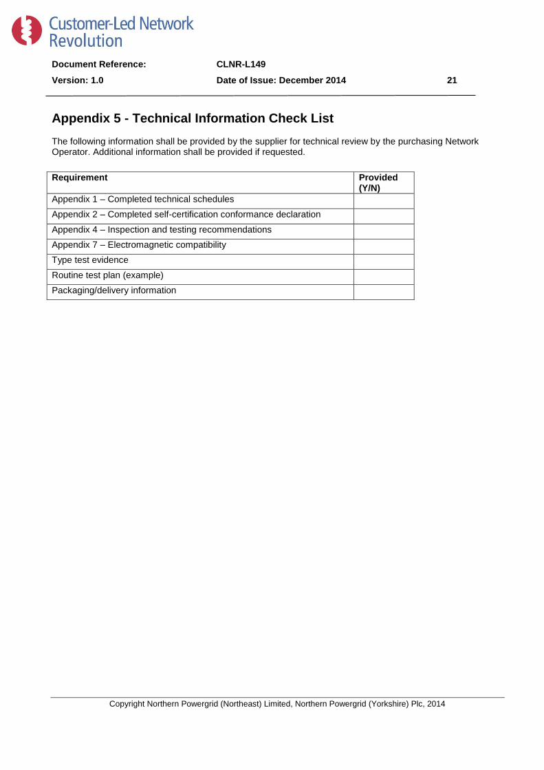
Appendix 5 - Technical Information Check List The following information shall be provided by the supplier for technical review by the purchasing Network Operator. Additional information shall be provided if requested.
Requirement Provided (Y/N)
Appendix 1 – Completed technical schedules Appendix 2 – Completed self-certification conformance declaration Appendix 4 – Inspection and testing recommendations Appendix 7 – Electromagnetic compatibility Type test evidence Routine test plan (example) Packaging/delivery information

Document Reference: CLNR-L149
Version: 1.0 Date of Issue: December 2014 22
Copyright Northern Powergrid (Northeast) Limited, Northern Powergrid (Yorkshire) Plc, 2014
Appendix 6 – Schedule of Components
Item Description Price
1 Weather Measurement Devices
2 On-line measurement devices.
3 Local controllers
4
5
6

Document Reference: CLNR-L149
Version: 1.0 Date of Issue: December 2014 23
Copyright Northern Powergrid (Northeast) Limited, Northern Powergrid (Yorkshire) Plc, 2014
Appendix 7 – Electromagnetic Compatibility
Electromagnetic Compatibility Tests for equipment
All equipment shall be compatible with the following generic EMC standards:
• BS EN 61000-6-3: 2007 - Generic Emissions standard • BS EN 61000-6-2: 2005 - Generic Immunity standard • BS EN 61000-4-2: 1995 - Electrostatic discharge immunity Test ((Requirement Air 8kV, Contact 4kV) • BS EN 61000-4-3: 2006 Radiated radio Frequency, Electromagnetic Field Immunity. (Requirement
80MHz-1GHz @ 10V/m) • BS EN 61000-4-6: 2007 Immunity to conducted disturbances induced by radio frequency fields (Requirement 150kHz - 80MHz @ 10V/m) • BS EN 61000-4-4: 2004 Electrical Fast Transient/Bursts Immunity (Requirements +/- 1kV).