Technical Report No. 2006 - 528 - Queen's...
35
Technical Report No. 2006 - 528 A SURVEY ON MULTI-HOP CELLULAR NETWORKS † Y. HUNG TAM School of Computing Queen’s University Kingston, Ontario, Canada K7L 3N6 [email protected] December 23, 2006 Abstract Wireless mobile communications technology has been evolving rapidly in the past decade. The number of mobile subscribers has reached 2 billions and is expected to reach 3 billions by the end of 2010. Most countries have already deployed or have started to deploy the third generation (3G) wireless cellular networks. In 3G, in addition to traditional voice service, users are provided with multi-media data services and a wide range of data rates up to 2 Mbps. Although high data rates are achieved, the inherent cell capacity and cell coverage limitations of these networks still exist. The capacity limitation raises the hot spot problem in a busy city centre or a large crowd situation such that many call requests are blocked. There is also the dead spot problem which occurs when signals between mobile users and base stations are blocked by obstructions. Recently, there have been proposals to apply the multi-hop relaying concept to existing cellular networks to enhance their capacity and coverage. We call these networks multi-hop cellular networks. As these networks consist of cellular and ad hoc components and, as a result, have their own issues and characteristics, designing a good multi-hop cellular network is a non-trivial task. In this survey, we first provide an overview of wireless networks including cellular networks and ad hoc networks. We then examine existing multi-hop cellular network proposals in terms of architectural design, medium access, routing, channel assignment and load balancing. Some open issues associated with these networks are also discussed. Keywords: 3G, Cellular Networks, TDD, W-CDMA, Relaying, Channel Assignment, Routing, Load Balancing, Ad hoc Networks, Multi-hop Cellular Networks. † This project was supported in part by the Natural Sciences and Engineering Research Council of Canada (NSERC) and Communications and Information Technology Ontario (CITO).
Transcript of Technical Report No. 2006 - 528 - Queen's...

Technical Report No. 2006 - 528
A SURVEY ON MULTI-HOP CELLULAR NETWORKS†
Y. HUNG TAM
School of Computing Queen’s University
Kingston, Ontario, Canada K7L 3N6 [email protected]
December 23, 2006
Abstract Wireless mobile communications technology has been evolving rapidly in the past decade. The number of mobile subscribers has reached 2 billions and is expected to reach 3 billions by the end of 2010. Most countries have already deployed or have started to deploy the third generation (3G) wireless cellular networks. In 3G, in addition to traditional voice service, users are provided with multi-media data services and a wide range of data rates up to 2 Mbps. Although high data rates are achieved, the inherent cell capacity and cell coverage limitations of these networks still exist. The capacity limitation raises the hot spot problem in a busy city centre or a large crowd situation such that many call requests are blocked. There is also the dead spot problem which occurs when signals between mobile users and base stations are blocked by obstructions. Recently, there have been proposals to apply the multi-hop relaying concept to existing cellular networks to enhance their capacity and coverage. We call these networks multi-hop cellular networks. As these networks consist of cellular and ad hoc components and, as a result, have their own issues and characteristics, designing a good multi-hop cellular network is a non-trivial task. In this survey, we first provide an overview of wireless networks including cellular networks and ad hoc networks. We then examine existing multi-hop cellular network proposals in terms of architectural design, medium access, routing, channel assignment and load balancing. Some open issues associated with these networks are also discussed. Keywords: 3G, Cellular Networks, TDD, W-CDMA, Relaying, Channel Assignment, Routing, Load Balancing, Ad hoc Networks, Multi-hop Cellular Networks.
† This project was supported in part by the Natural Sciences and Engineering Research Council of Canada (NSERC) and Communications and Information Technology Ontario (CITO).

i
Contents
Abstract List of Acronyms 1 INTRODUCTION 1 2 WIRELESS NETWORKS 2 2.1 Evolution of Wireless Communications 2 2.2 Cellular Networks 3 2.2.1 Medium Access 4 2.2.2 Channel Assignment 6 2.2.3 Hand-off 6 2.2.4 Load Balancing 6 2.2.5 Wireless Local Area Networks (WLANs) 7 2.2.6 Merits and Limitations of Cellular Networks 8 2.3 Ad hoc Networks 9 2.3.1 The Ad hoc Network Concept 9 2.3.2 Routing 9 2.3.3 Load Balancing 10 2.3.4 Merits and Limitations of Ad Hoc Networks 10 2.4 Cellular Networks Vs. Ad hoc Networks 10 3 MULTI-HOP CELLULAR NETWORKS 11 3.1 The Multi-hop Cellular Concept 11 3.2 Multi-hop Cellular Proposals 12 3.2.1 Summary of Multi-hop Cellular Proposals 20 3.3 Design Issues in Multi-hop Cellular Networks 22 3.3.1 Architectural Design 22 3.3.2 Medium Access 24 3.3.3 Channel Assignment 25 3.3.4 Routing 26 3.3.5 Load Balancing 27 3.4 Summary of Open Problems 27 4 CONCLUSIONS 29
Reference

ii
List of Acronyms 1G 1st Generation Wireless Communication Systems 2G 2nd Generation Wireless Communication Systems 3G 3rd Generation Wireless Communication Systems 3GPP 3rd-Generation Partnership Project 4G 4th Generation Wireless Communication Systems A-Cell Ad hoc-Cellular network A-GSM Ad Hoc Global System Mobile ACK ACKnowledgement AODV Ad-Hoc On-Demand Distance Vector AP Access point ALBAR A-Cell Load BAlancing Relaying ALBA A-Cell Load BAlancing ACAR A-Cell Adaptive Routing ARS Ad hoc Relaying Station BCR Base-Centric Routing BS Base Station CBM Cellular Based Multi-hop CDMA Code Division Multiple Access DSDV Destination-Sequence Distance Vector DSR Dynamic Source Routing DSSA Delay-Sensitive Slot Assignment E-DSSA Extended Delay-Sensitive Slot Assignment FDD Frequency Division Duplex FDMA Frequency Division Multiple Access GPS Global Positioning System GSM Global System for Mobile communications HMCN Hierarchical Multi-hop Cellular Network HWN Hybrid Wireless Network iCAR integrated Cellular and Ad hoc Relay IS-95 Interim Standard 95 ISM Industrial Scientific and Medical LDPR Location Dependent Packet Relay. MAC Medium Access Control MANET Mobile Ad Hoc NETwork MCN Multi-hop Cellular Network MRAC Multi-hop Radio Access Cellular MT Mobile Terminal ODMA Opportunity-Driven Multiple Access PSTN Public Switching Telephone Networks QoS Quality of Service PARCelS Pervasive Ad hoc Relaying for Cellular System RNC Radio Network Controller TDD Time Division Duplex TDMA Time Division Multiple Access UMTS Universal Mobile Telecommunication System W-CDMA Wideband Code Division Multiple Access WiMAX Worldwide Interoperability for Microwave Access WMN Wireless Mesh Network

1
1. INTRODUCTION Mobile communications have become affordable and popular over the past decade. The number of subscribers continues to grow and is expected to reach three billions in 2010 [Wray05]. These communications are facilitated by infrastructure-based wireless networks that are commonly or conventionally called cellular networks. For infrastructure-less wireless networks, there are ad hoc networks [Toh01]. Cellular networks are designed based on the Cellular concept that was introduced by Bell Laboratories in the 1960s. These networks are mainly designed and used for wireless voice communications. Recently though the influence of Internet applications such as instant messaging, e-mail, media file downloading and streaming made data communications become an important function of cellular networks. In fact, the cellular concept has widely been applied in wireless data communications networks such as wireless local area networks (WLANs) [Stal00]. Conventional cellular networks are grouped into generations. A new generation is distinguished from a previous one mainly in terms of technology and data-rates. Currently, many countries have implemented or started implementing third generation (3G) cellular networks. In 3G, in addition to traditional voice service, users are provided with a wide range of data and multi-media services with data rates up to 2 Mbps. Although these achievements represent a great success in mobile communications, inherent capacity and coverage limitations of cellular networks still exist. Limited cell capacity raises the hot spot problem such that call requests are frequently blocked in a busy city center or sport event where a big crowd is present. There is also the dead spot problem which occurs when communication links between mobiles and base stations (BSs) are blocked because of obstructions. Recently, the multi-hop relaying concept was proposed to address these limitations and problems, giving rise of multi-hop cellular networks. With multi-hop relaying, signals from a source node can be relayed to a BS through intermediate relaying devices. In this case, a high power long-range transmission can be divided into several low power short-range transmissions. This reduces the transmission power of the source node and the BS, and, thus, the interference of a cell. As 3G employs the wideband code division multiple access (W-CDMA) technology which is interference-limited, the reduction in interference increases the capacity of a cell [Radw06]. With multi-hop relaying, the hot spot problem can be alleviated by relaying the traffic from a hot (congested) cell to its neighboring cool (non-congested) cells [De02]. The connectivity for dead spots can also be improved by relaying the signals around obstructions. The idea of multi-hop relaying can be implemented by using carrier-owned (dedicated) or user-owned relaying devices. In the former case, high equipment and administrative cost may be incurred. Also, a carrier-owned relaying device usually has limited mobility, which reduces the flexibility of the network to handle the highly dynamic traffic situation in 3G systems. On the other hand, using user-owned relaying devices induces no extra infrastructure cost. If these devices are mobile terminals, the flexibility of the networks increases and, thus, the networks may be able to handle the dynamic load situation of the networks. Using mobile terminals as relaying devices is not a new idea. This is basically the idea of ad hoc networks [Toh01] that has been studied for more than a decade. While ad hoc networks have no central controllers or BSs, a multi-hop cellular network does have BSs or access points (APs). Although the idea of using mobile terminals for relaying seems a viable solution, it inherits the problems and issues of ad hoc networks such as relatively low reliability and high overhead

2
involved in routing and medium access. Existing ad hoc networks algorithms and protocols may not be suitable or effective for multi-hop cellular networks. As multi-hop cellular networks increases the cell capacity [Radw06], extends the cell coverage, and alleviates the hot spot and the dead spot problems, these networks could be a good solution for future generation or 4G [Esma03] wireless networks. There are some existing proposals for these networks. However, there is a lack of agreement as to which one is the best. In fact, there are other issues, such as, to name a few, quality of service (QoS), handoff, admission control, and user mobility, that have not been addressed. Also, current cellular networks have their own issues and characteristics. Thus, to design a good multi-hop cellular network, a detailed examination of existing multi-hop cellular networks proposals as well as the issues and characteristics of both cellular networks and ad hoc networks are required. Open problems of multi-hop cellular networks should also be identified. This is the objective of this survey. In the next section, we provide an overview of wireless networks specifically on cellular networks and ad hoc networks. In Section 3, a detailed examination of each existing multi-hop cellular networks proposal in terms of architecture, medium access, channel allocation, routing, and load balancing is provided. Open issues are also discussed. Section 4 concludes this survey. 2. WIRELESS NETWORKS Wireless communications are facilitated by wireless networks which basically consist of two types: infrastructure-based and infrastructure-less. In the infrastructure-based wireless networks category, we have networks that are mainly for voice communications and networks that are mainly for data communications. The former is conventionally called cellular networks whereas the latter is commonly called wireless local area networks (WLANs) [Stal01]. Technically, WLANs can be considered as cellular networks. For infrastructure-less wireless networks, there are ad hoc networks [Toh01], also called mobile ad hoc networks (MANETs) [Ko98]. In this section, we provide an overview of these wireless networking platforms. 2.1 Evolution of Wireless Communications In 1897, Guglielmo Marconi who invented radio communications first demonstrated the continuous radio contacts with the ships in the English Channel [Rapp02]. Since then, mobile wireless communications technologies have evolved. However, the growth of mobile communications was very slow until the introduction of the cellular concept by Bell Laboratories in the 1960s, the advancement in the fabrication of digital and radio frequency (RF) circuit, and the portability of wireless device. Since then, the wireless communications era has begun. The cellular concept is to divide a large coverage area into many small coverage areas which are called cells. The channels (frequency bands) used in one cell are reused in another cell if there is sufficient distance between these two cells to avoid signal collisions. In this way, the number of users that can be served increases while the frequency spectrum remains the same. This greatly improved the bandwidth utilization. Figure 1 illustrates the idea of frequency reuse. Frequency A is reused in every cell which is approximately 1.5 times the cell size apart.

3
2.2 Cellular Networks Wireless networks are traditionally and mainly designed for voice communications. These networks are infrastructure-based and are commonly called cellular networks.
Cellular networks have gone through three generations. In the first generation (1G), analog frequency modulation (FM) technique with Frequency Division Multiple Access (FDMA) and Frequency Division Duplex (FDD) were used. In the second generation (2G), digital modulation technique with Time Division Multiple Access (TDMA) or narrowband Code Division Multiple Access (CDMA) and FDD were used [Rapp02]. In 2G, in addition to traditional voice communications, limited data communications services such as Internet access and Short Messaging Service (SMS) are also provided. Two popular 2G standards are Global System Mobile (GSM), and Interim Standard 95 (IS-95 or cdmaOne). The former is based on TDMA whereas the latter is based on CDMA. In the third generation (3G), wideband CDMA air interface technology is used. This technology is basically a CDMA technology spread over a wider frequency band than 2G standards. The wide frequency band allows a higher user data rate up to 2Mbps. Users can then be provided with a wide range of services with different data-rates
a) Conventional cellular systems
Figure 2 Cellular systems: a) conventional (1G, 2G, 2.5G), and b) 3G
b) 3G cellular systems
MSC PSTN
PSTN
RNC
Core Network
The Internet
Mobile terminal
BS
BS
BS
BS
BS
BS
B C
A
A
C
B C
B
A
B
C
A
C A
B
A
A C B A
Figure 1 Frequency reuse in cellular systems
Cell size (1 unit in diameter)
1.5 units apart

4
depending on their needs. Examples of such applications are video conferencing, and video streaming. Examples of 3G standards are Universal Mobile Telecommunication Systems (UMTS) or WCDMA, and cdma2000 [Rapp02]. A cellular network basically consists of mobile terminals (MTs), base stations (BSs), and a mobile switching center (MSC). The MSC connects the MTs through the BSs to the public switched telephone networks (PSTN). Figure 2a shows the components of a traditionally cellular system such as 1G and 2G systems. In 3G, a radio network controller (RNC) [Holm04] is used instead of a MSC. The RNC connects with a core network which is the gateway to the Internet and the PSTN (see Figure 2b). The RNC coordinates the BSs and is responsible for radio resource management. 2.2.1 Medium Access Medium access techniques can be grouped into two types: contention-free and contention-based. The former is used in conventional cellular networks while the latter is typically used in WLANs. Contention-Free Medium Access A contention-free medium access technique provides a mobile terminal or a connection a dedicated channel in form of a frequency, a spreading code, a time-slot-frequency pair, or a time-slot-code pair. This technique provides a relatively more reliable wireless access service and induces low medium access overhead. However, it requires a more intelligent central controller such as a base station (BS). Examples of contention-free medium access techniques are Frequency Division Multiple Access (FDMA), Orthogonal Frequency Division Multiple Access (OFDMA), Time Division Multiple Access (TDMA), Code Division Multiple Access (CDMA) and Time Division Duplex CDMA (TDD-CDMA) [Rapp02]. These techniques can also be grouped into two types: bandwidth-limited, and interference-limited. FDMA, OFDMA and TDMA are bandwidth limited whereas CDMA and TDD-CDMA are interference limited.
In FDMA, each frequency represents a channel. The capacity of a cell is equal to the total number of channels. Figure 3a shows an example of FDMA having three channels. A similar version of FDMA is the Orthogonal Frequency Division Multiple Access (OFDMA) or Orthogonal Frequency Division Multiplexing (OFDM). The idea is to split the signals into multiple sub-signals and send them simultaneously at different frequencies to the receiver. OFDM helps to reduce the signal interference.
c1
c1
c2
c3
c2
c3
c4
Frequency
Time
Frequency
Time
a) FDMA b) TDMA
c5
c6
c7
c8
c9
c10
c11
c12
Frequency
Time
Codec) CDMA
c1
c2
c3
Figure 3 Multiple (medium) access techniques: a) FDMA, b) TDMA, and c) CDMA

5
TDMA is an overlaying technology on FDMA such that each frequency band is divided into a number of time slots. Each user can be assigned one or more time-slots. In this way, more users can be served or higher user data rates can be achieved. Figure 3b shows one frequency band is divided into 4 time-slots such that there are total 12 frequency-time-slot pairs (channels). If each time-slot is assigned to one user, 12 users can be accommodated simultaneously. Obviously, the capacity of a cell is dependent on the number of frequency bands that are available. Thus, both FDMA and TDMA are categorized as bandwidth-limited [Rapp02] technologies. CDMA is based on code division. Each user or connection is assigned a different spreading code (sequence) [Rapp02]. All users can simultaneously send their signals to the same destination on the same frequency if each user uses a different code. Thus, one frequency can be reused for all cells in the system. Figure 3c illustrates the concept of CDMA. Although the frequency spectrum in a CDMA system is fully utilized, interference becomes a major issue affecting the quality of transmission and reception. When the transmission power of a mobile terminal or a BS increases, interference increases and, thus, the transmission quality decreases. If the quality of a call, usually in terms of bit error rate, is below a predefined threshold, the call is dropped. This issue limits the number of users that can be served or the total data rate of a cell. Thus, CDMA is categorized as an interference-limited technology. CDMA is characterized by cell breathing and the near-far problem. The cell breathing effect is as follows: when the coverage of a cell increases, the capacity of the cell decreases and vice versa; and results from interference. The near-far problem occurs when two mobile terminals, one is far from the BS and the other one is near the BS, are simultaneously sending signals to the BS using the same power levels. As signals attenuate when they travel, signals from the closer terminal arrive at the BS stronger than that of the terminal farther away. This makes the BS unaware of or unable to recognize the signal of the farther terminal. Power control schemes exist for handling this problem [Holm04].
To allow a user to talk and listen at the same time, full duplex communications is required. There are two types of full duplex techniques: Frequency Division Duplex (FDD) and Time Division Duplex (TDD) [Holm04]. FDD requires two frequencies: one for uplink and one for downlink whereas TDD requires just one frequency, but at least two time slots: one for uplink and one for downlink. Figure 4 illustrates examples of FDD and TDD techniques. FDD is suitable for symmetric traffic whereas TDD is suitable for asymmetric traffic in terms of channel utilization.
3 time-slots for downlink
Frequency A (uplink)
Frequency B (downlink)
a) FDD a) TDD
Figure 4 Operation of FDD and TDD techniques
Frequency B (uplink and downlink)
1 timeslot for (uplink)
BS BS

6
2.2.2 Channel Assignment Channel or frequency reuse in cellular networks is an important factor for capacity improvement. A channel assignment strategy could affect the channel reusability and is important as well. Channel assignment strategies can be categorized into two types: fixed and dynamic. Fixed channel assignment (FCA) is to assign channels to the cells permanently. The advantage of FCA is that it is simple to implement. However, FCA may not fully utilize the cell capacity. For example, if a call request arrives in a congested cell in which channels are used up, the call will be blocked even though there are available channels in the neighboring cells. Dynamic channel assignment (DCA) is to assign channels dynamically among cells depending on real-time information such as interference situation, and the cost of channel reallocation. This way, the channels can be assigned in a cost-effective way and the radio resource is better utilized. 2.2.3 Handoff When a mobile user is in an on-going session and moves from one cell to another cell, the MSC transfers the call from the channel of the previous cell to a channel of the new cell. This process is called handoff. There are three types of handoff: hard, soft, and softer. Hard handoff refers to assigning different radio channels (frequencies) during a handoff. Thus, the user may experience the discontinuity of the call during the handoff process. Soft handoff allows the call of a user to be handed over without disruption. This is achieved by connecting the user to the old cell and the new cell simultaneously. The MSC chooses the connection that has the best quality. Softer handoff is similar to soft handoff except that it takes place between the sectors within a cell instead of between cells. 2.2.4 Load Balancing Load balancing in a network is the act of distributing the network load (traffic) evenly across the network such that the performance of the system is enhanced. In cellular networks, load balancing is about the distribution of the network traffic evenly among cells to enhance throughput and to reduce call blocking and call dropping probability. This can be done through either relaying or non-relaying techniques. For the former case, we categorize them as multi-hop cellular networks that is described and discussed in Section 3. For the latter case, some existing proposals such as channel borrowing [Das97], bandwidth migration and call preemption [Kim03], cooperative negotiation [Din03], and redirecting flexible users [Vanl02], are described below. The idea of channel borrowing [Das97] is that a hot cell borrows enough channels (frequency or bandwidth) for itself and its adjacent hot cells from its neighboring cooler cells. Although this idea works in conventional cellular networks, it is not applicable in 3G systems because there are no extra channels (frequencies) that can be borrowed. In 3G, one frequency can be reused in the whole network. Bandwidth migration and call preemption [Kim03] are based on on-line bandwidth migration and reservation. Network conditions are measured on-line (or in real-time) and preemption decisions of existing calls is made. Cells are classified as Peak cell (P-cell), Potential Peak cell (PP-cell), and Safe cell (S-cell). A P-cell is a hot cell that needs to borrow bandwidth from other cells. A PP-cell has reserved bandwidth such that it will not lend or borrow bandwidth from other cells. An S-cell is a cool cell that can lend bandwidth to P-cells. Network load that will be migrated is unified to reduce migration overhead. The idea of call preemption is to preempt low value calls for high value calls. The value of a call depends on the bandwidth requirements and the priority

7
of the call. Although performance results show that throughput increases and that call dropping and blocking probabilities decrease, this scheme is not suitable for CDMA systems because no additional bandwidth (frequency) can be migrated or borrowed in CDMA systems. In [Din03], a cooperative (coverage) negotiation approach was presented. The idea is to change the cell size (coverage) based on the loading situation of cells by varying the antenna pattern. The antenna pattern in a hot cell contracts to reduce the size of the serving area while the antenna patterns of the neighboring cool cells of the hot cell expands to cover the area that was originally covered by the hot cell. As the serving area in the hot cell reduces, the number of users needed to be served is also reduced. Thus, congestion is reduced and the call blocking probability is lowered. Expanded neighboring cool cells serve the users which are originally served by the hot cell. In other words, traffic of hot cells is shifted to these cooler cells. Load balancing among cells is achieved. The decision of cell size is based on the cooperative negotiation between congested cell and its neighboring cells. This approach assumes constant cell capacity over cell size. However, this is not the case in CDMA systems in which capacity of a cell decreases as coverage increases. This approach also requires complex antenna technology. In [Vanl02], directing or redirecting flexible users in the overlapping regions of cells was proposed. These users have the flexibility to communicate with any of the cells which covers this region. When one cell is hot, new calls or current calls in the overlapping region of the cell can be directed to one of its adjacent cooler cells. Obviously, this scheme has limited usage because it depends on the existence and the size of the overlapping region, and the number of active users (or mobiles) in the overlapping region. 2.2.5 Wireless Local Area Networks (WLANs) A wireless local area network (WLAN), also known as Wireless Fidelity (WiFi), is basically a wireless version of Ethernet where the user terminals are mobile. A WLAN has two modes of operation: infrastructure and ad hoc. For infrastructure mode, an access point (AP) is needed. A mobile terminal communicates with other mobile nodes or the Internet through the access point. So, technically, a WLAN in this mode can be considered as a cellular network. For ad hoc mode, mobile terminals communicate with each other directly in a peer-to-peer fashion.
Figure 5 Two modes of Wireless LANs:
Like Ethernet, WLANs mainly provide data communications services. They do not consist of the hardware specially designed for voice communications. Thus, the structure of an access point is much simpler than the BS of a cellular network. As voice over Internet Protocol (VoIP) technology has become popular, WLANs could also provide voice communication. However, the
a) Infrastructure mode a) Ad hoc mode
AP

8
voice quality of WLANs may not be as good as that of conventional cellular networks because the voice packet goes through the Internet instead of a dedicated switching circuit. The medium access technique of WLANs is based on the IEEE 802.11 medium access control (MAC) standard and is mainly a contention-based protocol. Thus, no channel assignment and admission control mechanisms are required. The IEEE 802.11 MAC protocol [Leon00, Stal00] has two modes of operation: Distributed Coordinate Function (DCF) and Point Coordinated function (PCF). DCF is based on Carrier Sense Multiple Access with Collision Avoidance (CSMA/CA). It uses physical channel sensing or virtual sensing. When physical channel sensing is used, a mobile node actually senses the medium. If the medium is idle, it sends packets; otherwise, the node defers transmission until the medium is idle. If a signal collision occurs, the node backs off for a period of time and tries again later. In virtual sensing, Request-To-Send (RTS), Clear-To-Send (CTS), and Acknowledge (ACK) signals, in addition to an ACK timer, are all used for coordinating the data transmissions. PCF is built on top of DCF with a coordinator added. The coordinator polls the mobiles to see if they have data to send. PCF provides a contention-free period for the mobiles to assure their access. The advantage of contention-based techniques is that they require no central administration. They are suitable for distributed networks such as ad hoc networks. However, this involves high overhead for signal collision resolution. Recently, WLANs have become popular because they are cheap and easy to manage and deploy. They are cheap because the free Industrial Scientific and Medical (ISM) bands are used and the access point (or wireless router) is a simple and low cost device. Although WLANs have these merits, their power level is restricted. Thus, their coverage is quite small (varying from 30m to 164m depending on the number and types of obstacles encountered by the signals). This makes them only suitable for providing services in a relatively small area, such as cafés, train stations, airports, and hotels. Also, several WLANs may exist in the same area. This increases the chance of co-channel interference that degrades the overall performance of the networks. Recently, various siblings of WLANs are in the market. For examples, there are Bluetooth and Worldwide Interoperability for Microwave Access (WiMAX). Bluetooth [Tane02] is used for even a smaller area which suits personal work place. The IEEE 802.15 wireless Personal Area Network (WirelessPAN) is a wireless standard similar to Bluetooth. WiMAX, which is associated with IEEE 802.16 Wireless Metropolitan Area Network (WirelessMAN) standard [Tane02], provides larger coverage than WiFi. The medium access technology of Bluetooth is based on centralized TDMA whereas medium access in WiMAX is based on OFDMA (see Section 2.2.1). 2.2.6 Merits and limitations of Cellular Networks As conventional cellular networks consist of intelligent BSs and RNCs for channel assignment and resource management, relatively more reliable services can be provided. In addition, contention-free medium access techniques can be used such that high medium access overhead can be avoided. A cellular network has no energy consumption issue of the BSs or access points because they are wired. The limitations of cellular networks are cell capacity and cell coverage. The limited cell capacity raises the hot spot (congested area) problem which usually occurs in a busy city centre or sport event where there are many users. Another problem of cellular networks is the dead spot problem in which signals are blocked by obstructions even when users are within the transmission range of a BS.

9
2.3 Ad hoc Networks Ad hoc networks [Toh01], also called packet radio networks [Murt95] or mobile ad hoc networks (MANETs) [Ko98], have been studied since late 1970’s. These networks are self-organized and self-configured networks. They are flexible and suitable to be deployed in battle fields, military actions, and emergency rescue operations where no network infrastructure is available. Although these networks have existed for a long time, they have not been implemented commercially because of their inherited unreliable characteristics: frequent disconnections due to users’ mobility and mobiles’ limited battery life. Recently, there is increasing interest in applying this concept to fixed wireless infrastructure to provide a low cost and flexible extension to the existing infrastructure-based wireless networks. For example, these networks can facilitate signal relaying in cellular networks. 2.3.1 The Ad hoc Network Concept Ad hoc networks consist of a number of mobile nodes which communicate with each other over the wireless medium in a peer-to-peer fashion. Communications between source and destination node is made through multi-hopping through other intermediate nodes. No existing network infrastructure or central administration is available or required. Figure 6 illustrates the idea of ad hoc networks. In the figure, although node D is outside the transmission range of node A, node A can still communicate with node D through the intermediate nodes B and C. Naturally, routing is a major issue in such networks. Another main issue is medium access. Ad hoc networks are usually designed based on contention-based medium access protocols, such as the IEEE 802.11 MAC protocol which incurs high overhead. There are proposals of using contention-free medium access, such as TDMA, for these networks. However, extra overhead for channel synchronization among mobile terminals is required.
2.3.2 Routing Routing protocols significantly affect the throughput and packet delay in ad hoc networks. These protocols can be categorized into two types: table-driven and demand-driven [Toh01]. In table-driven routing, each mobile node maintains one or more routing tables to store the routing information. The routing information is periodically updated throughout the network. Thus, each mobile node has consistent and up-to-date routing information of all nodes. However, periodical updating consumes network resources. An example of table-driven routing protocols is
Figure 6 Ad hoc networks
A
B
Transmission Range
CD

10
Destination Sequenced Distance Vector (DSDV) [Peki94] routing, which is an extension of the distributed Bellman-Ford routing algorithm [Stal00]. In demand-driven or on-demand routing, no route discovery is initiated unless there is a need. Periodic updates and event-triggered updates are partly or fully eliminated. Therefore, routing overhead is greatly reduced. This is the reason why these protocols are preferred for ad hoc networks. The most prominent on-demand routing protocols are Dynamic Source Routing (DSR) [John96] and Ad hoc On-Demand Distance Vector (AODV) [Peri94]. 2.3.3 Load Balancing Unlike cellular networks, ad hoc networks have no central controller or BSs. Thus, load balancing of these networks is amongst mobile terminals to reduce nodal congestion as opposed cell congestion. Fairness among nodes and quality of service (QoS) instead of call blocking probability are the issues to consider. The load balancing scheme in ad hoc networks is usually incorporated with a routing protocol. With this idea, traffic can be evenly distributed among mobile nodes such that the load in the network can be balanced and a higher throughput can be achieved. Examples of this idea are load-aware routing, multi-path routing of packets, and route de-coupling routing. The Load-Balanced Ad hoc Routing (LBAR) [Hass01] is a load-aware routing protocol. LBAR adds load awareness to existing ad hoc network routing protocols. In LBAR, the load of a MT is defined as a function of its activities and the activities of its neighboring nodes. The load information of each node along all possible paths from a source to its destination is sent to the destination during the route discovery process. The destination selects the best cost path based on the information and sends the decision back to the source. In [Pham02], a multi-path load balancing concept is proposed. Conventional ad hoc network routing protocols, such as DSR or AODV, send packets through a single path. By using multi-path routing, packets can be sent from a source to a destination through several paths such that traffic can be distributed among nodes. This helps avoiding traffic concentration on a single route. In [Roy03], the zone-disjoint routing was introduced to address the route-coupling problem (interference among paths) by selecting a route that has minimum overlapping area with the zones of other routes to minimize the route coupling. In this protocol, each node maintains the status information (active or inactive) of its neighboring nodes and computes the best next hop node based on the topology and activities information. 2.3.4 Merits and Limitations of Ad hoc Networks Ad hoc networks have high flexibility, which means that they can deployed at anytime anywhere without worrying about the network infrastructure. However, they suffer from frequent disconnections due to user mobility and limited battery life of mobiles. This makes the network relatively less reliable. Multi-hopping also introduces longer packet delay. The connectivity of these networks also depends on the network topology. 2.4 Cellular Networks Vs. Ad hoc Networks Cellular networks and ad hoc networks are two different wireless paradigms. Cellular networks are centralized and infrastructure-based systems while ad hoc networks are distributed and infrastructure-less systems. The medium access technique for cellular networks can be contention-free or contention-based whereas ad hoc networks usually assume contention-based medium access technique. Table 1 summarizes the characteristics of cellular network and ad hoc

11
networks in terms of structure, systems, flexibility, infrastructure cost, transmission power, medium access, overhead, channel reuse, routing, reliability, quality of service (QoS), load balancing, limitations, and problems. Table 1 Characteristics of cellular networks and ad hoc networks 3. MULTIHOP CELLULAR NETWORKS The idea of multi-hop cellular networks helps to alleviate the hot spot and dead spot problems of cellular networks. Multi-hop communication can increase the cell capacity and cell coverage. In this section, we describe the multi-hop cellular concept and examine existing proposals of these networks. 3.1 The Multi-hop Cellular Concept When the concept of multi-hop relaying [Harr00] is applied to a cellular network, a multi-hop cellular network is formed. In such network, a mobile device communicates with the base station (BS) directly or through other relaying devices. If mobile terminals (MTs) are themselves used as relaying devices, the ad hoc networks concept applies. As multi-hop relaying is used, the coverage of a cell is extended. Such networks exploit a smaller number of BSs or lower transmission power. Thus, infrastructure cost can be reduced and more frequencies can be reused. Multi-hop relaying allows a shorter transmission distance that reduces the overall interference in a cell. This helps to increase the capacity of a cell in 3G or CDMA systems [Radw06]. Multi-hopping facilitates traffic relaying which alleviates the hot spot and dead spot problems, and helps to reduce call blocking and to balance the load among cells. Thus, the system throughput and resource utilization increases. In addition, relaying facilitates peer-to-peer communications, which further reduces the load of a cell. Thus, the overall system throughput and resource utilization are further increased. The tradeoff is that the network is more complex and the limitations of ad hoc networks exist.
Cellular Networks Conventional WLAN
Ad hoc Networks
Structure Infrastructure-based Infrastructure-less Systems Centralized Distributed Flexibility Low High Infrastructure Cost High Low Low Transmission Power High to Low Low Low Medium access Contention-free Contention-based Contention-based/ contention-free Overhead Handoff Medium contention Routing, Medium contention Channel reuse Low High High Routing No need Required Reliability Relatively high Relatively low Quality of Service Easy to assure Difficult to assure Load balancing Release BS congestion Release MT congestion Limitations Cell capacity, cell coverage Limited battery life, topology Problems Hot spot, dead spot Frequent disconnections,
signal collisions

12
3.2 Multi-hop Cellular Proposals In this section, we examine 13 existing multi-hop cellular proposals. Their features are summarized in Table 2 at the end of this section. ODMA Opportunity-Driven Multiple Access (ODMA) [Anti99] can be considered as the earliest multi-hop ad hoc relaying proposal for 3G cellular systems. The idea is to break a single-hop long-range transmission into multi-hop short-range transmissions. As the transmission distance is reduced, the transmission power and interference, as well, are reduced. This allows a higher cell capacity in 3G or CDMA systems because the systems are interference-limited. Multi-hop relaying also extends the coverage of a cell. The multi-hop path of ODMA is computed based on minimum total path loss. Path loss represents the attenuation of a signal when the signal travels over a path between a transmitter and a receiver. Figure 7 shows the operation of ODMA. Mobile nodes in a low data rate region, i.e. the region that is far away from the BS, can transmit at high data rates by using ODMA multi-hop relaying. For routing, a relaying node uses a probing mechanism to build a neighbor list. There are three probing modes: Full probing, Normal probing, and Non-probing. A relaying node chooses one of these modes based on the number of neighbors, the gradient to the BS of the neighbors, its own terminal speed, and battery power level. The gradient to the BS is a cost function over a particular path in terms of a propagation condition, the number of hops, and other system parameters. Although the idea of ODMA is good, it was considered as too complex for implementation at that time and has been dropped. In addition, the details and the performance evaluation of the routing scheme were not provided. The issue of channel assignment has not been addressed.
MADF In [Wu00], a load balancing multi-hop relaying scheme called mobile-assisted data forwarding (MADF) was proposed. The idea is to forward the packets of the source nodes of a congested cell to less congested cells through some forwarding agents. A forwarding agent can be a dedicated repeater or a user mobile terminal (MT). Channels are grouped into two types: fixed channel and forwarding channel. The former one is used for normal cellular usage while the latter one is used for traffic relaying. The set of forwarding channels is actually a small subset of the original set of channels. These channels are set aside for the packet forwarding (relaying) purpose and are managed by the forwarding agents. A forwarding agent decides whether it is available for forwarding packets. If a forwarding agent free channels for relaying packets, it broadcasts a “free” message to its neighbors. A user MT chooses a forwarding agent based on the quality of the signal of the agent. A forwarding agent may serve more than one source node (see Figure 8). Dedicated forwarding agents are assumed to be placed near the boundaries of cells. No routing protocol was proposed for this architecture. But the authors suggested that routing protocols for
Multi-hop short transmission distance (High bit rate) (ODMA) - Mobile node
Long transmission distance (Low bit rate)
Figure 7 Operation of ODMA
BS

13
this architecture could be similar to existing ad hoc routing protocols. Simulation results show that MADF improves system throughput in both ALOHA [Tane03] and TDMA systems.
MCN Multi-hop Cellular Networks (MCN) were proposed in [Lin00]. MCN is basically a combination of cellular networks and ad hoc networks. A source mobile terminal (MT) communicates with its destination directly or through other intermediate nodes, i.e., in a peer-to-peer communication mode, without going through the BS if the source node and destination node are in the same cell. The idea of MCN is to reduce the transmission range (cell size) of BSs or the number of BSs. The former is called MCN-p, while the latter is called MCN-b (see Figure 9). MCN assumes the IEEE 802.11 MAC protocol for simplicity. Neighboring cells are assumed to use different channels to avoid co-channel interference and synchronization. However, since the idea of MCN is to either reduce cell size or eliminate adjacent cells, co-channel interference among cells may be very little such that assigning different channels to neighboring cells may not be necessary. A further study on this issue may be required. If neighboring cells need to be assigned different channels, inter-cell channel assignment scheme needs to be designed. Simulation results show that the system throughput of MCN is better than a single-hop cellular network.
Figure 9 The two MCN architectures: a) MCN-p, and b) MCN-b
A routing scheme called Base-Centric Routing (BCR) [Hsu02] was developed for MCN. BCR is a hybrid protocol which consists of table-driven and demand-driven components. The BS keeps track of the network topology of its own cell by using a table-driven protocol. Each MT sends a table (list) of its neighboring nodes to the BS. A path is computed based on the topology
- BS
- Forwarding agent
Figure 8 Relaying through forwarding agents in MADF
A
B
- Mobile node / Forwarding agent
BSBS
BS
b) MCN-b has fewer base stations
a) MCN-p has reduced cell size Original cell size
Original cellular networks
- BS
∆
Reduced cell size BS
BS BS
BS
BS
BS
BS
BS
BSBS
BS
BS
BSBS
BS
BS
BS
BS

14
information at the BS. If a MT needs a route, it sends route request to the BS. If a MT is out of the transmission range of a cell or cannot get a route from the BS, the mobile terminal discovers the route using AODV. Simulation results show that BCR has better performance than traditional ad hoc network routing protocols when these protocols are applied to MCN. A-GSM Ad hoc Global System Mobile (A-GSM) [Agge01] is designed for GSM networks. Each mobile terminal (MT) has two interfaces: cellular and ad hoc. The cellular interface is used for communicating with the BSs of GSM networks. The ad hoc interface is used for peer-to-peer communications (see Figure 10). A contention-based medium access protocol, such as 802.11 MAC protocol, is assumed. Each interface corresponds to a different medium access system. While a source MT uses one interface to communicate in one system, it uses the other interface to monitor the situation of the other system. The choice of the interface of a source MT is dependent on the signal strength it receives from the BS and its neighboring nodes. A relaying MT offers to relay packets by broadcasting a beacon message which contains the BS reachability and route information. MT may or may not reach the BS. If a relaying MT can reach the BS, the number of hops required to reach the BS is also included in the information. The source MT chooses the best way to communicate with the BS. For call handover (handoff) process, three successive phases are involved: Radio measurement, Initiation and trigger, and Handover control. A MT measures the signal strength of the radio link to the BS and the radio links to its neighboring nodes. A handover may be initiated and triggered if the serving BS has failed, the signal quality (bit error rate or carrier to interference ratio(C/I)) of current link is degraded, or some conditions were changed due to user mobility. Simulation results show on average 8~17 percent improvement in system throughout for different MT and dead spot populations.
HMCN A Hierarchical Multi-hop Cellular Network (HMCN) [Li02] is a cellular infrastructure consisting of sub-cells within a cell. The sub-cell is also called multi-hop cell, which is managed by an access point (AP) or a multi-hop capable node (MHN) (see Figure 11). A MHN can be a fixed station or a MT which is capable to perform packet scheduling, re-route a packet, and perform handover process. Each MT has two interfaces: one is for the communications with the BS and the other is for the communications with the AP or the MHNs. These two interfaces were suggested to be cellular and WLAN technologies, respectively. The MHNs are suggested to be placed on traffic lights such that power supply is not an issue. A routing scheme, called Cellular Based Routing (CBR), is proposed for this architecture which consists of centralized and distributed components. Mobile nodes collect and send neighborhood information to the BS periodically. When a mobile node needs to send packets to a destination node, it checks its routing table to see if there is a route to the destination. If a route is available, the mobile node
Figure 10 Two modes of communications: cellular (GSM) and ad hoc
BS
GSM-2G

15
uses the route; otherwise, it sends a route request to the BS. This reduces routing overhead and eases control.
Synchronous LDPR LDPR [Kwon02] stands for Location Dependent Packet Relay protocol. Synchronous LDPR is designed for TDD CDMA networks. Like ODMA, Synchronous LDPR uses multi-hop short-range transmissions to reduce the transmission power. The decision whether a mobile node should communicate with the BS or through other intermediate mobile nodes is based on data delay sensitivity and the signal strength the mobile receives from the BS. If the data is delay-sensitive, the source node sends the data packets directly to the BS. If the data is delay-insensitive, the source node may send the data packets through other relaying nodes depending on the signal strength of the BS. If the signal strength of the BS is greater than a predefined threshold, the mobile node communicates directly to the BS; otherwise, the mobile broadcasts a relaying request message to its neighbors. If its neighbors have better quality links to the BS, they reply to the mobile node. Then, the mobile node selects the neighbor with the best quality link for the connection. The link between the neighbor and the BS may also involve multi-hopping. The selection of the next hop node of the neighbors is also based on the signal strength. If no relaying node is suitable or available for packet relaying, the source node sends the data packet directly to the BS. In this protocol, no routing mechanism is required. Packets are forwarded based on hop by hop strategy, i.e., each relay node chooses the next hop node for packet forwarding. Although this idea can assure the quality of connections, the threshold may not be easy to decide. If the value of the threshold is too high, there is a higher chance for a source node to request multi-hop relaying. If the threshold is too low, most source nodes may communicate with the BS directly and the capacity and interference reduction gain may not be significant. iCAR Integrated Cellular and Ad Hoc Relay (iCAR) [De02, Wu03] was introduced to balance the load among cells by using low cost limited mobility ad hoc relay stations (ARSs). These ARSs are controlled by a mobile switching center (MSC) and are placed in hotspot (congested) areas to relay excessive traffic from hot (congested) cells to their neighboring medium hot cells. Traffic is further relayed to outer cooler cells so that congestion of the hot cells is reduced, call blocking probability of these cells is reduced, and load is balanced among cells. An ARS has two air interfaces: cellular and relaying. The cellular interface is used for ARS-to-mobile or ARS-to-BS communications. The interface uses a licensed frequency band. The relaying interface is used for mobile-to-ARS and ARS-to-ARS communications. This interface uses the Industrial, Scientific, and Medical (ISM) bands [Rapp02] which are free. As licensed bands and ISM bands are different frequency bands, there is no interference between them. Routing in iCAR is based on
Figure 11 Relaying through user terminal, AP, or dedicated repeater
BS
Traffic light post for power supply
AP

16
both hierarchical and flat routing [Tane03]. In the Hierarchical routing, routers are divided into regions. Each router knows how to route a packet to the destination within its own region, but does not know the routing structure of the other regions. Figure 12 illustrates the concept of iCAR. Traffic of mobile A is relayed to adjacent BS through ARSs. In iCAR, there are three types of relaying strategies: primary, secondary, and cascade (see Figure 12). Primary relaying is simply to relay the signal of a mobile node to a neighboring cell. Secondary relaying is to free-up a channel of an on-going connection of a neighboring cell such that there is a channel available for the primary relaying. Cascade relaying is to apply the secondary relaying twice such that the effect of secondary relaying is passing along the neighbors of the neighboring cells.
PARCelS Pervasive Ad hoc Relaying for Cellular System (PARCelS) [Zhou02] is similar to iCAR except that it uses mobile nodes instead of ARSs for relaying. This avoids extra equipment cost, maintenance, and handling for the ARSs. It is also more flexible. However, it inherits the limitations of ad hoc networks because of using mobile nodes for relaying. Routing in PARCelS is as follows: A BS sends out a congestion status signal periodically. When a BS indicates that it is congested, the mobile nodes in that cell search for routes to other cells which have more free channels. Each mobile node computes the best relay route based on battery life, mobile node speed and route length, and sends the route information to its BS, which selects the best routes based on the location and the status of the other potential destination BSs for load balancing purpose. The route searching (discovery) may involve high overhead. MRAC In the Multi-hop Radio Access Cellular (MRAC) [Yama02] architecture, relay stations are used to facilitate multi-hop packet relaying. These stations can be dedicated stations, such as fixed stations and wireless routers, or user mobile terminals. A source node chooses to communicate with BS directly or through these relaying stations based on the value of path loss. The number of hops for relaying is either one or two. The idea is to make use of the path diversity to reduce transmission power, and thus the interference. As interference is reduced, the capacity increases.
Cascade relaying (Free-up D’s link for E’s link)
- BS
- ARS
Three-tier cell system
C C
M C
M H
M C C
C
C C
C M M
C
C C M
Figure 12 Relaying through ARSs in a three-tier cell system
Secondary relaying (Free-up B’s link for C’s link)
A
B
Primary relaying Original link
C
D EBS
BS
BS
BS
BS

17
This is especially important when source nodes are near to the edge of a cell. These nodes need to use high transmission power for their signals to reach the BS. Figure 13 illustrates a scenario of this architecture. Based on this scenario, the authors show that MRAC helps to reduce transmission power and, thus the interference, whereas the coverage is enhanced.
HWN Hybrid Wireless Networks (HWN) [Hsei01] are a hybrid of cellular networks and ad hoc networks. A cell uses either a cellular mode or an ad hoc mode for communications. The choice of mode of a cell is determined by the BS of the cell. The mode that contributes a higher throughput would be chosen. The BS informs the MTs which mode they should use. When a cell is in the cellular mode, the MTs in the cell communicate through the BS. When a cell is in the ad hoc mode, the MTs communicate with each other without going through the BS. In this proposal, the authors also proposed a similar approach as HWN except that a MT can communicate with other MTs without the involvement of the BS if the number of hops between the source and the destination is within two hops. In this architecture, MTs are assumed to be equipped with GPS. In [Kuma02], the authors extended the HWN architecture and compared the performance of MCN-p and HWN. Simulation results show that MCN-p has a higher throughput that HWN. The reason is that the route maintenance process of MCN is assisted by the BS whereas HWN uses flooding. Thus, MCN has less routing overhead. Also, MCN-p always uses small cell size whereas HWN toggles between large cell size and small cell size based on estimated throughput. Therefore, MCN-p always has high spatial reuse and, thus, high throughput. HWN do have merit over MCN-p in terms of network partitioning (connectivity). In [Chan03], a hybrid wireless network protocol is proposed. This work is similar to HWN except that this protocol only allows either one-hop or two-hop communications for ad hoc communications. If no route exists, the source node communicates with the BS. This avoids long multi-hop route which is less reliable. The authors provide a detailed description on the information exchange process between a source node, a BS, a destination node, and intermediate nodes. Simulation results show that the two-hop communication mode has lower call blocking and call dropping probabilities. CBM A Cellular Based Multihop (CBM) network [Li03] basically consists of two networks: a cellular network and an ad hoc network. The ad hoc network is inside the cellular network and allows
Figure 13. Relaying through dedicated repeater or user terminals based on path loss
Medium propagation loss with high antenna gain
Medium propagation loss
High propagation loss
Dedicated repeater
Source mobile
Relay mobile
Low propagation loss
BS

18
peer-to-peer communications. A MT has two interfaces: cellular and WLAN. The cellular interface is assumed suitable for UMTS systems. For control signals and delay-sensitive data, the cellular interface is used while, for delay-insensitive data, the WLAN interface is used. A routing scheme called Cellular Based Source Routing (CBSR) was developed to facilitate routing for the ad hoc network component. Each mobile node sends out hello messages to its neighbors periodically. Each MT maintains a neighbor list and sends the list to the BS periodically. In this way, the BS can construct the topology of the network. When a MT has packets to send, it checks its route cache to see if there are routes to choose. If there are routes, it chooses the best route among them. If there is no route, it sends a route request to the BS. The BS computes a route based on the topology information. If a route is found, the route is sent to the MT; otherwise, an error message is sent to the MT. This shows that a BS plays an important role in the routing processing in this architecture. Simulation results show CBSR outperforms DSR in terms of packet delivery ratio, average delay and routing overhead. A-Cell The Ad hoc-Cellular (A-Cell) architecture [Safw03, Safw05] is designed for TDD W-CDMA cellular networks. A-Cell is similar to ODMA except that it uses directive antennas [Ohir00a, Ohir00b] to increase spatial (channel) reuse and the Global Positioning System (GPS) to facilitate routing. Like ODMA, A-Cell assumes transmission over short distance to reduce interference, thus, to achieve a higher data-rate. A-Cell also assumes high mobile node density to reduce power consumption, and enhance cellular coverage and system throughput. Figure 14 shows the A-Cell relay architecture.
Figure 14 A-Cell relay networks architecture
Based on this architecture, the author formulated a channel assignment model called A-Cell channel assignment (ACA) [Safw04a] which is designed based on optimal edge coloring strategy. ACA utilizes a limited number of channels to enhance the channel reuse. Based on A-Cell and ACA, a channel assignment scheme called Delay-Sensitive Slot Assignment (DSSA) [Alri05] was developed based on the ACA model with an additional delay-sensitive feature. The idea of DSSA is to assign channels with the goal of maximizing channel reuse and minimizing packet delay. When proposing a channel to a mobile node, DSSA first uses neighborhood information of mobile nodes for channel information checking and elimination. Then, the channel that contributed the lowest time-slot waiting time (delay) will be chosen. DSSA ensures that no neighbors of the next hop node of the mobile node are transmitting on these channels and no neighbors of that node are receiving on these channels. For example, in Figure 15a, for the route A-B-G, node B is already assigned a channel (slot 4, code 2). Then, node A can be assigned any channel except (slot 3, code 1) because node C and E are respectively receiving and transmitting on this channel.
BS

19
Obviously, DSSA is suitable only for omni-directional antenna environments. When directional antennas are used, the neighborhood information checking technique of DSSA is no longer adequate (see Figure 15b). To handle this situation, the Extended Delay-Sensitive Slot Assignment (E-DSSA) [Tam06] scheme was developed. E-DSSA employs a transmission zone testing technique for channel information checking and elimination. This technique is more accurate than DSSA and eliminates unnecessary neighboring nodes for information checking and channel assignment. E-DSSA also avoids co-channel conflicts that occurs when a mobile terminal can send and receive signals simultaneously and the co-time-slot conflict that happens when a mobile terminal can either send or receive signals at one time simultaneously. In addition, E-DSSA adapts to different cell sizes (ranges) for a better use of radio resource.
In 3G or CDMA multi-hop environment, TDD CDMA [Esma03] instead of FDD CDMA is commonly used to avoid complex frequency switching for uplink and downlink signal transmissions in multi-hop cellular environment. Also, TDD is suitable for asymmetric traffic that would be the usual case in 3G environments. In WCDMA (or UMTS) standard, there are 15 slots per one transmission frame and each slot can have up to 16 codes [Holm04]. Thus, the maximum number of time-slot-code pairs (channels) in a transmission frame is 240 (see Figure 16).
In [Tam05], a load balancing and relaying framework, called A-Cell Load Balancing Relaying Framework (ALBAR) was proposed which is applicable to A-Cell. This framework includes a load balancing scheme called A-Cell Load Balancing (ALBA), a routing scheme called A-Cell
Figure 16. Channel in a UMTS TDD-CDMA transmission frame
Time
Code
16 codes
Frequency
15 slots
Figure 15 Channel assignment with omni-directional and directional antennas
B
a) Omni-directional antenna b) Directional antenna with flexible transmission range
A B
E D
A
E D
C
F
(slot 4, code 2)
(slot 3, code 1) (slot 3, code 1)
H - Mobile node
C
G G
F

20
Adaptive Routing (ACAR), and the E-DSSA, This framework integrates load balancing, routing and channel assignment functionalities to provide an integrated multi-hop relaying solution for the 3G environments. When the load difference among cells is greater than the threshold, load migration starts. ALBA chooses the source node for load migration based on the migration priority of the node which is calculated based on its distance from the target BS and the amount of traffic load it has. Once the source node for load migration is chosen, ACAR finds a reliable route for the source node to relay its traffic to the target cell. A reliable route consists of reliable relaying nodes that are chosen based on their current traffic and battery status. ACAR also considers the cell breathing characteristic of 3G or CDMA systems. Route discovery can be performed in a single hop for all nodes that are within the maximum transmission range of the BS simultaneously. Routing overhead could be reduced and call requests within the maximum coverage of a cell may still be served. ACAR employs an on-demand strategy. Therefore, the routing overhead is further reduced. Simulation results show that ALBAR balances the load among cells, reduces the call blocking ratio of a hot cell significantly and increases the system throughput. 3.2.1 Summary of Multi-hop Cellular Proposals The above multi-hop cellular proposals have similarities and differences. Table 2 summarizes these proposals in terms of several categories: architecture, medium access, routing scheme and load balancing scheme. In each category, there are sub-categories, for example, “Relaying device” is a sub-category of the category “Architecture”. Attributes of a proposal are identified by using an empty cell or one of the five symbols: “■”, “□”, “○”, “▲”, and “∆”. An empty cell (or a blank space) means that the proposed architecture or scheme does not have this feature or does not fall into this category. “■” represents the features or platforms or strategies suggested by the authors of the proposed architectures or schemes. “□” represents the features or platforms or strategies suggested by the authors without detailed explanations. For example, adaptive antennas were suggested to be used in HMCN, but there is no further description on the antennas or the use of the antennas. “○” is the assumptions made by the authors of the proposed architectures or schemes. “▲” represents the features of the schemes whereas the schemes are designed or proposed based on the proposed architectures. For example, there could be more than one channel assignment scheme or load balancing scheme for a proposed architecture. “∆” represents the features which are implied based on our understanding of the proposed architectures or schemes. For example, the use of IEEE 802.11 MAC protocol implies that the ISM bands are used. For ease of understanding and comparison, we provide a figure depicting the components of the proposed architectures (see Figure 17). In this figure, the architectures are grouped based on three major technologies: WLAN, 1G & 2G, and 3G. Note that the architectural design may span different technologies. This is because the wireless technologies have been evolving rapidly in the past decade. In Figure 17, HMCN and MRAC are similar in terms of the choice of relaying devices. In A-GSM and HWH, mobile nodes communicate by using either cellular mode or ad hoc mode. iCAR, PARCelS and MADF are basically based on 1G or 2G technology except that they have different choice of relaying device: iCAR uses ARSs, PARCelS uses mobile terminals whereas MADF uses both types of device. In MCN-p, a small cell size with WLAN technology is assumed. ODMA, LDPF, CBM, and A-Cell are developed for 3G or W-CDMA systems.

21
Table 2. Summary of different multi-hop cellular networks proposals
Architecture
Medium Access
Cha
nnel
A
ssig
nmen
t
Routing
Load
B
alan
cing
Proposal name & year Re
layi
ng D
evic
e
Gat
eway
Dev
ice
Inte
rfac
e
Freq
uenc
y Ba
nd
Cel
l Siz
e
Net
wor
k D
ensi
ty
Addi
tiona
l Mod
e
Supp
ortin
g Te
chno
logi
es
Con
tent
ion-
base
d
Con
tent
ion-
free
Relay Strategies
Con
trol
Car
rier
-
Ow
ned
Use
r-
ow
ned
WLA
N
WLA
N
1G, 2
G
3G, 2
G
Rela
ying
In
itiat
ion
Pos
ition
ing
Syst
em
Stat
iona
ry (R
epea
ter,
AP)
Lim
ited
mob
ility
(ARS
)
Stat
iona
ry (A
P, D
eskt
op)
Mob
ile te
rmin
al
Base
stat
ion
Acce
ss p
oint
(AP)
Sing
le
Dua
l
ISM
ban
ds
Lice
nse
band
Smal
l
Larg
e
Den
se
Spar
se
Peer
-to-p
eer
Ante
nna
(dir
ectio
nal,
adap
tive)
GPS
802.
11 D
CF,
ALO
HA
802.
11 P
CF
TDM
A, F
DM
A,
CD
MA,
W-C
DM
A
Set a
side
cha
nnel
s for
pac
ket f
orw
ardi
ng (r
elay
ing)
Inte
r-ce
ll ch
anne
l ass
ignm
ent
Nod
al c
hann
el a
ssig
nmen
t
BS re
acha
bilit
y
Hop
cou
nt li
mits
Path
loss
Link
qua
lity
( pac
ket l
oss)
Sign
al st
reng
th
Bit e
rror
rate
, C/I
Del
ay
Thro
ughp
ut
Forw
ardi
ng A
gent
Sour
ce n
ode
Cen
tral
ized
Dis
trib
uted
Amon
g ce
lls
Amon
g M
Ts
ODMA ‘99 ■ ■ ■ ■ ■ ∆ ∆ ■ □ ■ □ ○ MADF ‘00 ■ ■ ■ ■ ■ ∆ ∆ ■ ∆ ■ ■ ■ □ ■ ○ ▲
-b ■ ■ ■ ∆ ○ ∆ □ ■ ∆ ■ ▲ ▲ MCN ‘00 -p ■ ■ ■ ∆ ○ ∆ □ ■ ∆ ■ ▲ ▲ A-GSM ‘01 ■ ■ ■ ∆ ■ ■ ■ ■ ■ ■ □ □ □ ■ ∆ HMCN ‘02 ■ ∆ ∆ ■ ■ ■ ■ ∆ ■ ■ ■ □ ■ ■ ■ ■ ▲ ▲ LDPR ‘02 ■ ■ ■ ■ ∆ ■ □ □ □ ■ iCAR ‘02 ■ ■ ■ ■ ■ ∆ ■ ▲ ▲ PARCelS ‘02 ■ ■ ■ ■ ■ ∆ ∆ ■ ▲ ▲ □ MRAC ‘02 ■ ∆ ■ ■ ■ ■ ■ ∆ □ □ ■ ■ ■ HWN ‘03 ■ ■ ■ ∆ ○ ○ ○ ■ ■ □ ▲ ▲ CBM ‘03 ■ ■ ■ ■ ∆ ■ ∆ ○ ■ ■ ■ □ □ ▲ ▲ A-Cell ‘03 ■ ■ ■ ■ ○ ○ ■ ○ ■ ▲ ○ ▲ ▲ ▲ ▲
■- Suggested features or platforms or strategies by the authors of the proposed architectures or schemes □ - Suggested features or platforms or strategies by the authors of the proposed architectures or schemes without detailed explanations ○ – Assumptions made by the authors of the proposed architectures or schemes ▲- Suggested features of channel assignment scheme or routing schemes or load balancing schemes which are designed based on the proposed architectures ∆ - Implied features based on our understanding of the proposed architectures or schemes Empty cell (blank space) – the proposed architecture or scheme does not have this feature or does not fall into this category

22
Figure 17 Illustration of components and layout of multi-hop cellular proposals
3.3 Design Issues in Multi-hop Cellular Networks As aforementioned, various techniques have been proposed for multi-hop cellular networks in terms of architecture, medium access, routing, and load balancing. In this section, a detailed examination of each of the design issues involved is provided. 3.3.1. Architectural Design Architectural design of a network involves deciding the structure, the network components, the technologies, and the relationship among them. This may include, but is not limited to, choosing the relaying device, medium access technology, antenna technology, and positioning technology. Relaying Device Relaying in wireless networks is about deciding the way to relay traffic from one node to another when they may not be within the range of each other. For cellular environments, a destination node within a cell is typically a BS or an access point (AP). For peer-to-peer communications, the destination node is a mobile node. A relaying device can be a carrier-owned or user-owned relaying device. A carrier-owned device can be a stationary device or a limited mobility ad hoc relay station (ARS). A stationary device can be a dedicated repeater, an access point, or a wireless router. A user-owned relaying device can be a stationary device or a mobile terminal. A user-owned stationary device can be an access point, a wireless router, or a wireless access enabled desktop. Using a carrier-owned device for relaying provides a more reliable and secure access, but induces considerable infrastructure, administration, and maintenance cost. The idea is also less flexible. By contrast, using a user-owned device for relaying provides more flexibility at no extra infrastructure cost, but it is relatively less reliable and less secure. If user mobile terminal is used, frequent disconnections due to the users’ mobility and mobiles’ limited battery life may occur.
ODMA
3G
A-Cell
1G & 2G
LDPF
BS
A-GSM, HWN
HMCN
BS
iCAR
PARCelS
MADF
CBMWLAN
WLAN
WLAN
BS
MRAC
MCN-p MCN-b
Mobile and/or forwarding agent ARS and/or forwarding agent
Dedicated repeater
Access point

23
These are the inherent problems of an ad hoc network. To decide which type of relaying device to use, the characteristic of current wireless technology should be considered. As 3G provides users a range of services with a wide range of data-rates, the traffic patterns could be highly dynamic. Traffic of a cell is no longer strictly proportional to the number of users, but also to the types of services that the users requested. Users may simultaneously have several connections such as video conferencing and music streaming. This requires a larger cell capacity. The time and location of users are difficult to be predicted. Hot spot (congested area) could happen in anytime anywhere. Thus, a carrier-owned stationary or limited mobility relaying device is inflexible to deal with this situation unless the traffic patterns are known ahead. But, still, extra infrastructure cost is induced. Thus, using user-owned devices such as mobile terminals is a better choice whereas carrier-owned dedicated devices may be used as auxiliary devices. In fact, most multi-hop cellular proposals assume mobile terminals as relaying devices (see Table 2). As mobile terminals are used, the ad hoc networks concept applies. This raises the routing issue. Gateway Device In Table 2, a gateway device can be a BS or an AP. In fact, a BS can be considered as an access point but with high power (large coverage) and the ability for radio resource management, channel assignment, signal modulation and demodulation, handoff and power control. A BS is more expensive than an AP and is normally used in conventional cellular networks. An AP is usually referred to as the gateway of a WLAN, and is a much simpler and cheaper device. Note that a wireless router in the market also provides the functions of an AP. As both BSs and APs are popular devices and widely deployed, they should be considered when designing the architecture for future generation wireless networks. From an economical point of view, the architecture using access points as accessing devices is very attractive. However, the coordination among access points becomes issues. For voice or real-time multi-media communications, a conventional BS is certainly a better choice in terms of quality assurance. Interface and Frequency Band A mobile terminal with dual interface, one for cellular network access and the other for ad hoc network access, is more flexible and may gain capacity advantage. This design simplifies the architecture and avoids interference between the two systems: cellular and relaying. This also allows the user to access two systems simultaneously. For example, one interface can be used for accessing the cellular network in which licensed frequency bands are used and the other one may be used for accessing the network, such as a WLAN or an ad hoc network, in which the ISM bands are used. The tradeoff is that the quality of a connection using ISM bands may not be assured because there are other users who compete for the medium (frequency bands). The number of users may also be unpredictable. In addition, a terminal with dual interface is more expensive because of the additional circuitry and hardware components. Cell Size and Network Density Some multi-hop cellular proposals, such as MCN-p and A-Cell, are based on the assumption of a small cell size and a dense network. A small cell size allows higher cell capacity gain, higher frequency reuse, and lower power consumption. Dense network increases the network connectivity and network reachability. Unfortunately, these assumptions also pose limitations. With a small cell size and a sparse network, many nodes may be not able to reach the BS. The resource may not be fully utilized. Thus, the cell size and network density issues require further investigations. Figure 18 illustrates this situation. Nodes A, B, and D become unreachable after a conventional cellular network is changed to a MCN-p (utilizing small cell size).

24
Figure 18: Communications in a) conventional cellular networks, and b) MCN-p
Additional (Communications) Mode Some multi-hop cellular network architectures have peer-to-peer communications mode in addition to the basic cellular communications mode. This reduces the load of a cell. However, the distance between a source node and a destination node is limited by the maximum number of hops imposed by the relaying strategy. In other words, a source node and its destination node should be in the regions that are close to each other. Supporting Technologies The use of directive antennas helps decoupling multi-path routes and reducing interference. This concept is applicable in 3G or CDMA systems. When interference is reduced, cell capacity increases. In addition, the use of directional antennas increase spatial (channel) reuse, and reduce power consumption and interference. Although directive antennas for mobile node are useful, this technology is still in developing stage. A positioning system for mobile node is useful for facilitating routing [Ko98] in multi-hop networks. Recently, the Global Positioning System (GPS) has become popular. As the price of GPS has become more affordable, most mobile terminals may be equipped with GPS in future. Thus, when designing the architecture of multi-hop cellular networks, GPS may need to be considered. While a GPS receiver needs to be on the satellite’s line of sight, the performance of GPS could be degraded because of bad weather or indoor usage. Other positioning technologies may also need to be considered. 3.3.2 Medium Access In multi-hop cellular environments, contention-based or contention-free medium access techniques can be used (see Table 1). As contention-based medium access requires no infrastructure or central controller, it is suitable for the ad hoc component of a multi-hop cellular network. It can also be applied to a BS or an access point. It is also simple and low cost to implement. The trade-off is that they may have higher medium access overhead because of signal
D
B
Normal cell sizeReduced cell size
•
BS BS
a) Single-hop communications in conventional cellular networks
b) Multi-hop communications in MCN-p
C
D
A
B
AC
- Source node

25
collisions. They also suffer from hidden and exposed terminal problems. For commercial implementation, ISM bands, which involve no licensing cost, can be used. Thus, bandwidth utilization is not a major concern of the service provider. In addition, these bands do not cause interference to cellular licensing frequency bands or consume the cellular capacity. The trade-off is that this introduces medium competition with other non-cellular users. The transmission power is also restricted, thus, the transmission range is relatively small. QoS may not be assured. Two examples of contention-based medium access protocols are IEEE 802.11 DCF mode and the ALOHA protocol [Tane03] (see Table 2). In a contention-free medium access scheme, there is no signal collision, co-channel interference, hidden terminal or exposed terminal problems. Thus, bandwidth is better utilized. It also provides more reliable and secure service. Although these techniques require a central controller, the present of the controller has an advantage in administrating the ad hoc network component of the networks to improve the overall network performance. As different types of contention-free medium access scheme have different characteristics. This factor should be considered when designing the architecture. Examples of contention-free medium access scheme are IEEE 802.11 PCF mode, FDMA, TDMA, and CDMA (see Table 2). Proposals of hybrid medium access techniques are also available. In this case, a MT is equipped with two interfaces: cellular and ad hoc. The cellular interface uses licensed band with contention-free access scheme whereas the ad hoc interference uses free ISM bands with contention-based access scheme. As both access techniques are well-developed and widely used, it should be easily to combine these two techniques (technologies) in one mobile device. The ad hoc interface also allows the communications with other wireless systems, such as WiFi and Bluetooth. Although contention-free medium access techniques seem to be a better choice in terms of overhead and QoS, they require an effective channel assignment scheme. As well, a more sophisticated (hence more expensive) BS may be required. From an engineering point of view, a contention-free access technique is a better choice. From a commercial implementation perspective, a cost-benefit analysis should be conducted. 3.3.3 Channel Assignment In cellular networks, the channel assignment (allocation) problem usually deals with channel distribution among cells [Fu06]. Each BS is placed at a specific distance from each other to avoid interference. The main goal is to maximize the channel reuse. Each cell is assigned a number of channels that will not be used in its neighboring cells. Each cell is a discrete entity that does not communicate with its neighboring cells. In multi-hop cellular networks, the situation is more complex. In addition to the communications with the BS, each node may act as a tiny sub-cell and may communicate with its neighboring nodes. Thus, a channel allocation problem may involve channel assignment among cells (inter-cell channel assignment) or among nodes (nodal channel assignment). For example, MCN-p and MCN-b involve inter-cell channel assignment. When contention-free medium access techniques such as FDMA, OFDMA, TDMA, CDMA, are used within cells and among nodes, nodal channel assignment is also needed. This makes the channel assignment strategy more complex. Improper channel assignment strategies would greatly affect the performance of the networks. Although some proposed architectures are designed for contention-free multi-hop cellular environments, no nodal channel assignment schemes are proposed for them except A-Cell (see Table 1). There are two channel assignment schemes developed for A-Cell: DSSA and E-DSSA

26
(see Section 3.2). Both are heuristic solutions though. Optimal channel allocation is desirable from a performance point of view. Some multi-hop cellular proposals have the feature of setting aside some channels for packet forwarding. However, channel assignment schemes for selecting the channels are not available. 3.3.4 Routing Multi-hop relaying has many advantages. However, its effectiveness could be degraded by an ineffective routing protocol. Routing affects the throughput and delay of the systems. In multi-hop cellular environment, if relaying is done through dedicated relay stations such as ARSs, a hierarchical routing and flat routing scheme should be sufficient. If mobile terminals are involved in relaying, a more dynamic routing protocol might be needed. It is easy and convenient to assume ad hoc networks routing protocols (see Section 2.3.2). However, these protocols may not utilize the intelligence of the BS. Existing routing protocols for multi-hop cellular networks are BCR, CBR, CBSR, and ACAR that are designed for MCN, HMCN, CBM and A-Cell, respectively. BCR is better than common ad hoc networks routing protocols. However, it is still designed based on the assumption of a dense network. Its performance is degraded when the network is sparse. In addition, BCR chooses paths based on a small number of hop counts. This raises the fairness and energy efficiency issues. Nodes on the route which has a smaller hop count may always be chosen for relaying that could shorten the battery life of the nodes. Furthermore, BCR does not address the cell breathing characteristic of 3G cellular systems. ACAR is designed with the consideration of the cell breathing characteristic of 3G systems, load balancing, fairness, and energy consumption of relaying nodes. In addition, It is suitable for both densely and sparsely connected networks. However, there is a lack of performance evaluation of ACAR. The trade-off between the cell capacity and the cell size that affects the performance of ACAR should also be studied. In CBR and CBSR, mobile nodes collect neighborhood information and send to the BS for route computation. This helps to reduce the route computation overhead in mobile nodes. Some proposed architectures provide relaying strategies instead of detailed routing protocols. A relaying Strategy for multi-hop cellular architecture can be based on one or more of the criteria: BS reachability, hop count, path-loss, link-quality, signal strength, bit error rate, carrier-to-interference ratio (C/I), delay-sensitivity, and throughout. With BS reachability information provided by relaying nodes, mobile nodes can select the best next hop relaying node to reach the BS. The hop count affects the network reachability and may increase the chance of route disconnection or signal interference. When a route is broken or the quality of a route degrades, packets may be lost or corrupted. This may require the retransmission of the packets. This increases packet delay and decreases system throughput. The criteria, path loss, link-quality, signal strength, bit error rate, and C/I, are inter-related. Both signal strength and path-loss affect link quality. Bit error rate could be a link quality measure. A high quality link allows higher throughput as the chance of re-transmission due to packet corruption or loss is less. Not only a source node can initiate the relaying need, a relaying node or a forwarding agent could also take the lead by advertising their free channels or capacity for relaying (See Table 1). In other words, the overhead involved in relaying can be shared among source nodes and relaying nodes.

27
3.3.5 Load balancing Load balancing in multi-hop cellular networks should have two objectives: balancing the load among cells and balancing the load among MTs. The former one helps to reduce the call blocking probability or congestion at the BS and AP. Examples of this idea are iCAR, and PARCelS. The later one helps avoiding traffic congestion in the relaying routes and can be achieved by using a load-aware routing scheme. Although these two objectives seem to be separate issues, the coordination between them is important to obtain a good overall performance. For example, when a cellular load balancing component is activated, which source MT should be chosen for re-routing the traffic? ALBA addresses this issue. However, it is still a heuristic scheme. An optimal load balancing scheme for multi-hop cellular networks could be an interesting subject to study. 3.4 Summary of Open Problems For architectural design, using user mobile terminals for relaying seems to be a common choice in terms of flexibility and infrastructure cost. This is especially important in 3G environments in which the traffic load is highly dynamic. However, using mobile terminals as relaying nodes raises network security and reliability issues. As a compromise, proprietary (carrier-owned) dedicated relay stations and user mobile terminals may co-exist. In addition, user-owned fixed or temporary fixed devices are good choices for relaying because they are relatively reliable in terms of power supply and mobility. Fixed devices can be wireless access enabled desktop PCs or wireless routers. Temporary fixed devices can be mobile phones and laptops that are in charging or stationary state. The choice of relaying device can also be based on quality of service (QoS) requirements, cost-effectiveness, and backward compatibility and inter-operability with existing networks technologies. An AP is a simple, cheap, and popular device for wireless access to the data networks. However, its coverage is small. On the other hand, a conventional cellular network BS provides large coverage, but is more expensive. Recently, there is a proposal of wireless mesh networks (WMN) [Akyi05]. The idea is to interconnect a number of wireless mesh routers (APs) together to form a backbone of the networks. The backbone provides large coverage. These routers are dynamically self-configured and self-organized. Mobile terminals or other access points can access the Internet through the mesh router of this backbone. Although this idea seems promising, but if the ISM bands are used, signal collisions and medium contention from other users can be troublesome. If licensed bands are used, the cost becomes an issue. A cost-effective solution of using gateway devices should be an interesting subject for further study. Using dual interfaces for mobile terminals avoids co-channel interference between the cellular and the relaying systems. This design also simplifies the network architecture. The capacity of the system can also be increased by taking the advantage of using the ISM bands for one interface. However, as the ISM bands are free, the number of competitive users within the same area may be unpredictable. This raises QoS concerns, such as delay, data-rates, and packet loss. Dual interface terminals also have higher equipment cost. If service providers would like to utilize the ISM bands with “acceptable” quality, a QoS scheme will have to be developed. There is an idea of using ISM bands for best effort data service, while licensed bands are used for quality assured services. The cell size and the network node density affect the network (BS) reachability, which in turn affects the number of servable users and, thus, the system throughput. In Table 2, some of the proposals are designed based on the assumption of small cell size and a dense network. Small cell

28
size requires less transmission power. Thus, interference is reduced and cell capacity or frequency reusability increases. However, high network density is required to maintain the network connectivity or the BS reachability for extended cell coverage. However, these assumptions might not be suitable for the dynamic load and topology environment of 3G systems. Thus, the application of these architectures may be limited. Finding the optimal cell size of a multi-hop cellular network should be an interesting problem. Peer-to-peer communications mode of a multi-hop cellular network helps reduce the load of a cell. However, the distance between a source node and a destination node is limited by the maximum number of hops imposed by the relaying strategy. Finding an optimal number of hops for this network structure could be an interesting subject for study. Using directional antennas helps reduce interference and increase spatial reuse. Using GPS may help to reduce routing overhead. These technologies have high potential for future wireless communication systems. However, directional antennas for mobile device are still in early research and development stage. The applicability or performance of the directional antennas of mobile terminals requires further study. Equipping a directional antenna and/or GPS on a mobile terminal causes cost impact. This idea may not be cost-effective. A feasibility study of using them should be useful. If these technologies are not feasible or cost-effective, the architectural design and the related schemes might need to be designed based on traditional omni-directional antenna and/or without GPS. For medium access techniques, intuitively, contention-free medium access is better than contention-based medium access in terms of quality assurance and overhead. However, a more powerful and complex, thus expensive, BS may be required. In addition, a licensed frequency band is required; otherwise, signal collision-free condition could not be guaranteed. A cost-effective design should be interesting to explore. When contention-free medium access techniques are used, channel assignment strategies are required. Most existing proposals, which are designed for contention-free medium access environments, do not have channel assignment schemes. As well, existing channel assignment schemes are heuristic and centralized. In addition, these schemes are not fully dynamic, for example, in allocating uplink and downlink slots. As well, they focus on maximizing throughput and lowering the packet delay which are only some of the QoS requirements. Thus, an optimal, dynamic, and QoS-based channel assignment scheme is still an open problem. QoS classes and traffic burstiness also need to be considered. Different routing schemes are designed for different multi-hop cellular architectures. Thus, it is difficult to design a universal routing scheme for all these proposals. For 3G multi-hop cellular systems, ACAR seems to be a good routing solution. However, there is a lack of performance evaluation of ACAR. A further study on routing schemes for multi-hop cellular networks should be performed. Relaying strategy affects the system performance. The strategy can be based on BS reachability, hop count, path loss, link quality, signal strength of communication links, bit error rate, carrier-to-interference ratio (C/I), delay-sensitivity of data, and estimated system throughput. The workload (overhead) due to relaying or routing can be shared by relaying nodes, forwarding agents, and BS instead of concentrating on source nodes only. What an optimal or sub-optimal strategy should be is a good area to explore.
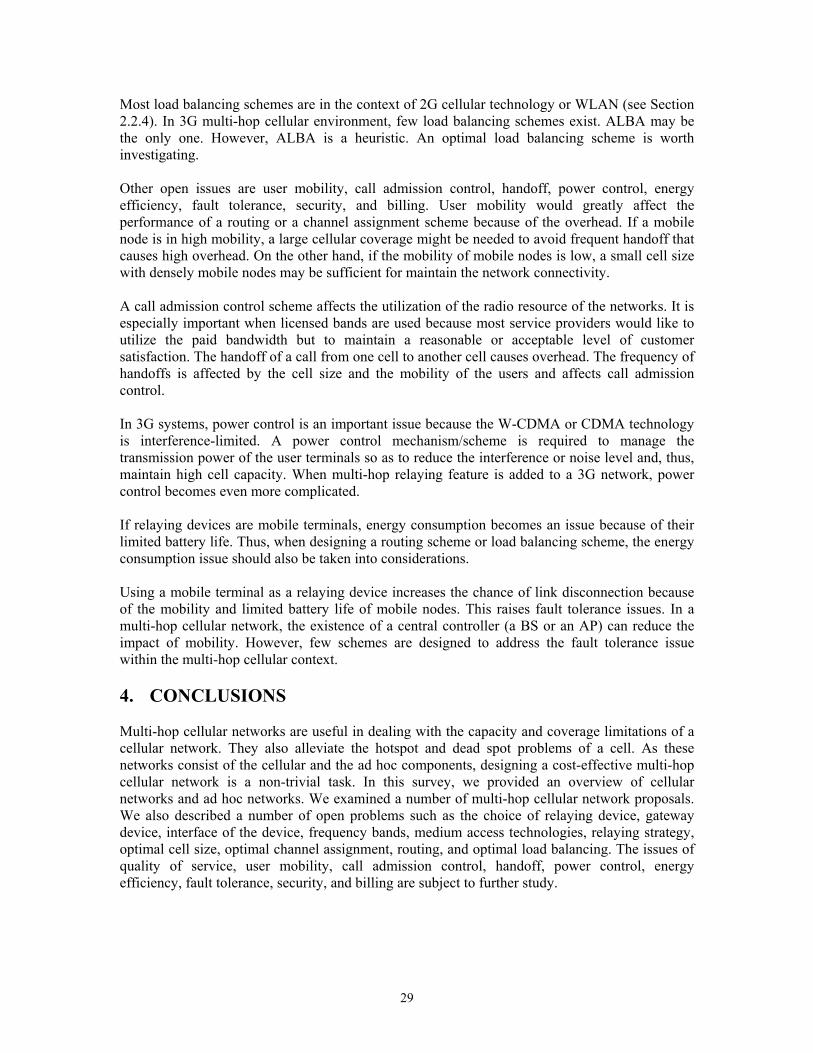
29
Most load balancing schemes are in the context of 2G cellular technology or WLAN (see Section 2.2.4). In 3G multi-hop cellular environment, few load balancing schemes exist. ALBA may be the only one. However, ALBA is a heuristic. An optimal load balancing scheme is worth investigating. Other open issues are user mobility, call admission control, handoff, power control, energy efficiency, fault tolerance, security, and billing. User mobility would greatly affect the performance of a routing or a channel assignment scheme because of the overhead. If a mobile node is in high mobility, a large cellular coverage might be needed to avoid frequent handoff that causes high overhead. On the other hand, if the mobility of mobile nodes is low, a small cell size with densely mobile nodes may be sufficient for maintain the network connectivity. A call admission control scheme affects the utilization of the radio resource of the networks. It is especially important when licensed bands are used because most service providers would like to utilize the paid bandwidth but to maintain a reasonable or acceptable level of customer satisfaction. The handoff of a call from one cell to another cell causes overhead. The frequency of handoffs is affected by the cell size and the mobility of the users and affects call admission control. In 3G systems, power control is an important issue because the W-CDMA or CDMA technology is interference-limited. A power control mechanism/scheme is required to manage the transmission power of the user terminals so as to reduce the interference or noise level and, thus, maintain high cell capacity. When multi-hop relaying feature is added to a 3G network, power control becomes even more complicated. If relaying devices are mobile terminals, energy consumption becomes an issue because of their limited battery life. Thus, when designing a routing scheme or load balancing scheme, the energy consumption issue should also be taken into considerations. Using a mobile terminal as a relaying device increases the chance of link disconnection because of the mobility and limited battery life of mobile nodes. This raises fault tolerance issues. In a multi-hop cellular network, the existence of a central controller (a BS or an AP) can reduce the impact of mobility. However, few schemes are designed to address the fault tolerance issue within the multi-hop cellular context. 4. CONCLUSIONS Multi-hop cellular networks are useful in dealing with the capacity and coverage limitations of a cellular network. They also alleviate the hotspot and dead spot problems of a cell. As these networks consist of the cellular and the ad hoc components, designing a cost-effective multi-hop cellular network is a non-trivial task. In this survey, we provided an overview of cellular networks and ad hoc networks. We examined a number of multi-hop cellular network proposals. We also described a number of open problems such as the choice of relaying device, gateway device, interface of the device, frequency bands, medium access technologies, relaying strategy, optimal cell size, optimal channel assignment, routing, and optimal load balancing. The issues of quality of service, user mobility, call admission control, handoff, power control, energy efficiency, fault tolerance, security, and billing are subject to further study.

30
Reference [Agge01] G. N. Aggelou, and R. Tafazolli, “On the Relaying Capability of Next-Generation
GSM Cellular Networks”, IEEE Personal Communications, vol. 8, no. 1, pp. 40-47, Feb. 2001.
[Akyi05] I. F. Akyildiz, and Xudong Wang, “A Survey on Wireless Mesh Networks,”IEEE Communications Magazine, Vol. 43, Issue: 9, pp.S23- S30, Sept. 2005.
[Alri05] M. Al-Riyami, A. M. Safwat and H. S. Hassanein, “Channel Assignment in Multi-hop TDD W-CDMA Cellular Networks,” IEEE International Conference on Communications (ICC), Vol. 3, pp. 1428 – 1432, May 2005.
[Anti99] 3rd Generation Partnership Project (3GPP); Technical Specification Group Radio Access Network; “Opportunity Driven Multiple Access,” Sophia Antipolis, Valbbonne, 1999. (3G TR 25.924 version 1.0.0)
[Chan03] R. Chang, W. Chen and Y. Wen, “Hybrid Wireless Network Protocols,” IEEE Trans. Vehicular Technology, vol. 52, no. 4, pp. 1099-1109, July 2003.
[Das97] S. K. Das, A.K. Sen and R. Jayaram, “A Structured Channel Borrowing Scheme for Dynamic Load Balancing in Cellular Networks,” IEEE ICDCS, 1997.
[De02] S. De, O. Tonguz, H. Wu and C. Qiao, “Integrated Cellular and Ad hoc Relay (iCAR) Systems: Pushing the Performance Limits of Conventional Wireless Networks,” 35th Annual Hawaii International Conference on System Sciences (HICSS), 2002.
[Din03] L. Din, J. Bigham, L. Cuthbert, P. Nahi and C. Parini, “Intelligent Cellular Network Load Balancing Using Cooperative Negotiation Approach,” IEEE WCNC, 2003.
[Esma03] R. Esmailzadeh, M. Nalagawa and A. Jones, “TDD-CDMA for the 4th Generation of Wireless Communications,” IEEE Wireless Communications, Aug. 2003.
[Fu06] X. Fu, A. G. Bourgeois, P. Fan, and Y. Pan, “Using a Genetic Algorithm Approach to Solve the Dynamic Channel-Assignment Problem,” International Journal of Mobile Communications, Vol. 4, No.3, pp. 333 – 353, 2006.
[Harr00] T. Harrold and A. Nix, “Intelligent Relaying for Future Personal Communication Systems,” IEEE Colloquium on Capacity and Range Enhancement Techniques for Third Generation Mobile Communications and Beyond, Digest No. 00/003, Feb. 2000.
[Hass01] H. Hassanein and A. Zhou, “Routing with Load Balancing in Wireless Ad hoc Networks,” In Proc. of the 4th ACM international workshop on Modeling, analysis and simulation of wireless and mobile systems (MSWIM), July 2001.
[Holm04] H. Holma and A. Toskala, “WCDMA for UMTS, Radio Access for Third Generation Mobile Communications,”3rd edition, John Wiley & Sons, 2004.
[Hsu02] Y.C. Hsu and Y.D. Lin, “Base-Centric Routing Protocol for Multi-hop Cellular Networks,” IEEE GLOBECOM, 2002.
[Hsei01] H.Y. Hseih, and R. Sivakumar, “Performance Comparison of Cellular and Multi-hop Wireless Networks: A Quantitative Study”, In Proc. of ACM SIMETRICS’01, Cambridge, pp. 113 – 122, June 2001.
[John96] D. B. Johnson and D. A. Maltz, “Dynamic Source Routing in Ad Hoc Wireless Networks,” Mobile Computing, Kluwer Academic Publishers, 1996.
[Kim03] S. Kim and P.K. Varshney, “Adaptive Load Balancing with Preemption for Multimedia Cellular Networks,” IEEE WCNC, pp. 1680-1684, 2003.
[Ko98] Y.-B. Ko and N. H. Vaidya, “Location-Aided Routing (LAR) in Mobile Ad hoc Networks,” ACM/IEEE International Conference on Mobile Computing and Networking (MobiCom), Oct. 1998.
[Kuma02] K. J. Kumar, B. S. Manoj, and C. S. R. Murthy, “On the Use of Multiple Hops in Next Generation Cellular Architectures”, In Proc. of IEEE Intl. Conf. on Networks ICON ’02, pp. 283 – 288, Aug. 2002.

31
[Kwon02] Y. H. Kwon, and D. C. Lee, “An Uplink Packet Relay Protocol for CDMA Cellular-like systems”, In Proc. of MILCOM 2002, Vol. 2, pp. 940 – 945, Oct. 2002.
[Leon00] A. Leon-Garcia and I. Widjaja, “Communication Networks,” McGrawHill, 2000. [Li02] H. Li, M. Lott, M. Weckerle, W. Zirwas, and E. Schulz, “Multihop Communications
in Future Mobile Radio Networks”, In Proc of the 13th IEEE Intl. Symposium on Personal, Indoor and Mobile Radio Communications, Vol. 1, pp. 54 – 58, Sept. 2002.
[Li03] H. Li, D. Yu, and H. Chen, “New Approach to Multihop – Cellular Based Multihop Network,” In Proc. of 14th IEEE on Personal, Indoor and Mobile Radio Communications, PIMRC 2003, Vol. 2, pp. 1629 – 1633, Sept. 2003.
[Lin00] Y. D. Lin and Y.C. Hsu, “Multihop Cellular: A New Architecture for Wireless Communications,” IEEE INFOCOM ’2000, 19th Annual Joint Conference of the IEEE Computer and Communications Societies. vol.3, pp.1273 – 1282, Mar. 2000.
[Murt95] S. Murthy, J. J. Garcia-Luna-Aceves, “A Routing Protocol for Packet Radio Networks,” In Proc. of the ACM/IEEE International Conference on Mobile Computing
and Networking (MOBICOM), pp. 86-95, 1995. [Norr04] L. Norr, and A. Anpalagan, “Dynamic Channel Allocation in TDD-CDMA systems,”
Telecommunications, IEEE Canadian Review, pp.9-13, summer 2004. [Ohir00a] T. Ohira and K. Gyoda, “Electronically Steerable Passive Array Radiator Antennas for
Low-cost Analog Adaptive Beamforming,” Phased Array Systems and Technology, 2000.
[Ohir00b] T. Ohira and K. Gyoda, “Design of Electronically Steerable Passive Array Radiator (ESPAR) Antennas,” Antennas and Propagation Society International Symposium, 2000.
[Peki94] C. E. Perkins and P. Bhagwat, “Highly Dynamic Destination-Sequenced Distance-Vector routing (DSDV) for Mobile Computers,” ACM Proc. SIGCOMM '94, pp. 234-244, Oct. 1994.
[Peki99] C. Perkins and E. Royer, “Ad-hoc On-demand Distance Vector Routing,” In Proc. of the 2nd IEEE Workshop on Mobile Computing Systems and Applications, pp. 90-100, Feb. 1999.
[Pham02] P. Pham and S. Perreau, “Multi-path Routing Protocol with Load Balancing Policy in Mobile Ad hoc Network,” Mobile and Wireless Communications Network, pp. 48-52, 2002.
[Radw06] A. Radwan and H. Hassanein, “Capacity Enhancement in CDMA Cellular Networks using Multi-hop Communication,” IEEE ISCC, June 2006.
[Rapp02] T. S. Rappaport, “Wireless Communications, Principles and Practice,” 2nd edition, Prentice Hall, 2002.
[Roy03] S. Roy, D. Saha, S. Bandyopadhyay, T. Ueda and S. Tanaka, “Directional Antenna: A Network-aware MAC and Routing Protocol for Effective Load Balancing in Ad hoc Wireless Networks with Directional Antenna,” In Proc. of the 4th ACM International Symposium on Mobile Ad hoc Networking and Computing(MobiHoc), June 2003.
[Safw03] A. Safwat, “A-Cell: A Novel Multi-hop Architecture for 4G and 4G+ Wireless Networks,” In Proc. of IEEE Vehicular Technology Conference (VTC), 2003.
[Safw04a] A. Safwat, “ACA: Channel Assignment in Ad hoc, 4G and Beyond Wireless Networks with Directional Antennas,” In Proc. of IEEE International Conference on Communications (ICC), Volume 6, pp.3143 – 3147, Jun 2004.
[Safw05] A. Safwat, “A Novel Multi-hop Architecture for Future Generations of Wireless Networks with Directional Antennas,” IEEE International Conference on Communications (ICC), Vol. 1, pp. 266 – 270, May 2005.
[Stal00] W. Stallings, “Data and Computer Communications,” 7th edition, Prentice Hall, 2000.

32
[Tam05] Y. H. Tam, A. M. Safwat, and H. S. Hassanein, “A Load Balancing and Relaying Framework for TDD W-CDMA Multi-hop Cellular Networks,” In Proc. of the 4th International IFIP-TC6 Networking Conference, pp. 1267-1280, May 2005.
[Tam06] Y. H. Tam, H. S. Hassanein, and S. G. Akl, “Effective Channel Assignment in Multi-hop W-CDMA Cellular Networks,” In Proc. of the International Wireless Communications and Mobile Computing Conference (IWCMC), July 2006.
[Tane03] A. S. Tanenbaum, “Computer Networks,” 4th edition, Prentice Hall, 2003. [Toh01] C. K. Toh, “Ad hoc Mobile Wireless Network, Protocols and Systems,” 1st edition,
Prentice Hall, 2001. [Vanl02] J.S.H. van Leeuwaarden, S. Aalto and J. Virtamo, “Load Balancing in Cellular
Networks using First Policy Iteration,” 5th Finnish teletraffic seminar, Feb. 2002. [Wray05] R. Wray, “Nokia Upbeat as It Predicts Mobile Users to Reach 3bn,” The Guardian
Unlimited Business, Feb 5 2005, http://business.guardian.co.uk/story/0,,1414725,00.html [Wu00] X. Wu, S. H. G. Chan, and B. Mukherjee, “MADF: A Novel Approach to Add an Ad-
Hoc Overlay on a Fixed Cellular Infrastructure”, In Proc. of Wireless Communications and Networking Conf. WCNC, Vol. 2, pp. 549-554, Sept. 2000.
[Wu03] H. Wu and C. Qiao, “Modeling iCAR via Multi-dimensional Markov Chains,” Mobile Networks and Applications, vol. 8, Jun. 2003.
[Yama02] Y. Yamao, T. Ostu, A. Fujiwara, and S. Yoshida, “Multi-hop Radio Access Cellular Concept for Fourth Generation Mobile Communications System”, In Proc. of 13th IEEE Int’l Symposium on Personal, Indoor and Mobile Radio Communications, Vol. 1, pp. 59 – 63, Sept. 2002.
[Zhou02] J. Zhou and Y. Yang, “PARCelS: Pervasive Ad-hoc Relaying for Cellular Systems,” In Proc. of Med-Hoc-Net, Sep. 2002.