REPORT No. 528
38
Transcript of REPORT No. 528
REPORT No. 528
REDUCTION OF HINGE MOMENTS OF AIRPLANE
CONTROL SURFACES BY TABS
By THOMAS A. HARRIS
Langley Memorial Aeronautical Laboratory
140293--35,------1 I
NATIONAL ADVISORY COMMITTEE FOR AERONAUTICS
HEADQUARTERS, NAVY BUILDING, WASHINGTON, D. C.
LABORATORIES, LANGLEY HELD, VA.
Created by act of Congress approved March 3, 1915, for the supervision and direction of the scientific study of
the problems of flight. Its membership was increased to 15 by act approved March 2, 1929. The members are
appointed by the President, and serve as such without compensation.
4b
JOSEPH S. AMES, Ph. D., Chairman,
President, Johns Hopkins University, Baltimore, Md.
DAVID W. TAYLOR, D. Eng., Vice Chairman.
Washington, D. C.
CHARLES Go ABBOT, Sc. D.,
Secretary, Smithsonian Institution.
LYMAN J. BRIGGS, Ph. D.,
Director, National Bureau of Standards.
BENJAMIN D. FOULOIS, Major General, United States Army,
Chief of Air Corps, War Department.
WILLIS RAt GREGG, B. A.,
Chief, United States Weather Bureau.
HARRY F. GUGOENHEIM, M. A.,
Port Washington, Long Island, N. Y.
ERNEST J. KING_ Rear Admiral, United States Navy,
Chief, Bureau of Aeronautics, Navy Department.
CHARLES A. LINDBERGH, LL.D.,
New York City.
WILLIA M. P. MAcCRACKEN, Jr., Ph. B.,
Washington, D. C.
AUGUSTINE W. ROBINS 9 Brig. Gen., United States Army,
Chief, MatGriel Division, Air Corps, Wright Field, Dayton_
Ohio.
EUGENe. L. VIDAL, C. E.,
Director of Air Commerce, Department of Commerce.
EDWARDP. WARNER, M. S.,Editor of Aviation, New York City.
R. D. WEYERBACHER, Commander, United States Navy,
Bureau of Aeronautics, Navy Department.
ORVILLE WRIGHT, Sc. D.,
Dayton, Ohio.
GEORGE W. LEWIS, Director of Aeronautical Research
JOHN F. VICTORY, Secretary
HENRY J. E. REID, Engineer in Charge, Langley Memorial Aeronautical Laboratory, Langley Field, Va.
JOHN J. IDE, Technical Assistant in Europe, Paris, France
TECHNICAL COMMITTEES
AERODYNAMICS AIRCRAFT ACCIDENTSPOWER PLANTS FOR AIRCRAFT INVENTIONS AND DESIGNSAIRCRAFT STRUCTURES AND MATERIALS
Coordination of Research Needs of Military and Civil Aviation
Preparation of Research Programs
Allocation of Problems
Prevention of Duplication
Consideration of Inventions
LANGLEY MEMORIAL AERONAUTICAL LABORATORY OFFICE OF AERONAUTICAL INTELLIGENCE
LANGLEY FIELD, VA. WASHINGTON, D. C.
Unified conduct, for all agencies, of Collection, classification, compilation,
scientific research on the fundamental and dissemination of scientific and tech-
problems of flight, nical information on aeronautics.
REPORT No. 528
REDUCTION OF HINGE MOMENTS OF AIRPLANE
CONTROL SURFACES BY TABS
By THOMAS A. HARRIS
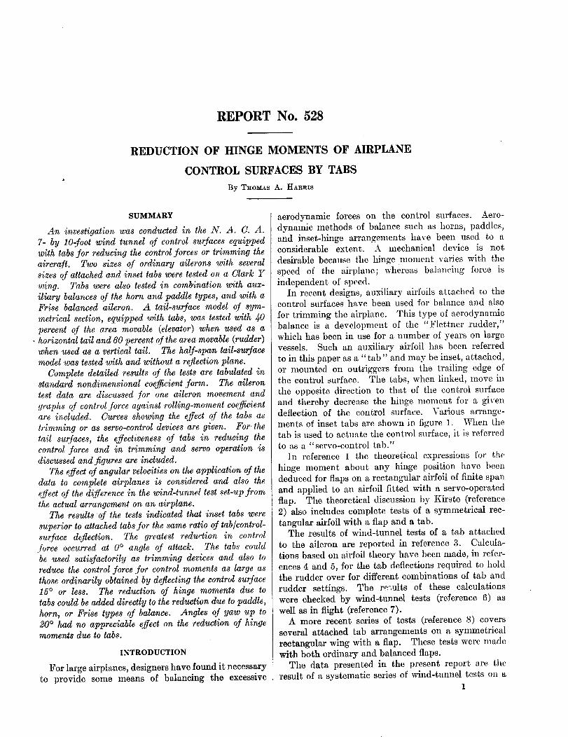
SUMMARY
An investigatio_ was conducted in the N. A. C. A.
7- by lO-.foot wind tunnel of control sur,faces equipped
with tabs for reducing the control,forces or trimming theaircraft. Two sizes of ordinary ailerons with several
sizes of attached and inset tabs were tested on a Clark Y
wing. Tabs were also tested in combination with aux-
iliary balances o,f the horn and paddle types, and with aFrise balanced aileron. A tail-surface model of sym-
metrical section, equipped with tabs, was tested with 40
percent of the area movable (elevator) when used as a• horizontal tail and 60 percent of the area movable (rudder)
when used as a vertical tail. The half-span tail-surfacemodel was tested with and without a reflection plane.
Complete detailed results of the tests are tabulated instandard nondimensional coe y_cient form. The aileron
test data are discussed for one aileron movement and
graphs of control,force against rolling-mome'nt coefficientare included. Curves showing the effect of the tabs as
trimming or as serve-control devices are given. For. the
tail surfaces, the effectiveness of tabs in reducing the
control -force and in trimming and serve operation isdiscussed and figures are included.
The effect o,f angular velocities on the application o,f the
data to complete airplanes is considered and also the
effect of the difference in the wind-tunnel test set-up,fromthe actual arrangement on an airplane.
The results of the tests indicated that inset tabs were
superior to attached tabs for the same ratio o,f tab�control-
surface deflection. The greatest reduction in controlforce occurred at 0 ° angle o,f attack. The tabs could
be used satis,factorily as trimming dew'ices and also toreduce the control -force .for control moments as large as
those ordinarily obtained by deflecting the control surface15 ° or less. The reduction of hinge moments due to
tabs could be added directly to the reduction due to paddle,
horn, or Frise types o,f balance. Angles o,f yaw up to20 ° had no appreciable effect on the reduction o,f hingemoments due to tabs.
INTRODUCTION
For large airplanes, designers have found it necessary
to provide some means of balancing the excessive
aerodynamic forces on the control surfaces. Aero-dynamic methods of balance such as horns, paddles,
and inset-hinge arrangements have been used to aconsiderable extent. A mechanical device is not
desirable because the hinge moment varies with the
speed of the airt)lane; whereas balancing force is
independent of speed.In recent designs, auxiliary airfoils attached to the
control surfaces have been used for balance and also
for trimming the airplane. This type of aerodynamicbalance is a development of the "Flettner rudder,"which has been in use for a number of years on large
vessels. Such an auxiliary airfoil has been referred
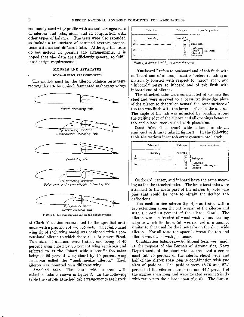
to in this paper as a "tab" and may be inset, attached,or mounted on outriggers from the trailing edge ofthe control surface. The tabs, when linked, move in
the opposite direction to that of the control surface
and thereby decrease the hinge moment for a givendeflection of the control surface. Various arrange-
ments of inset tabs are shown in figure 1. When thetab is used to actuate the control surface, it is referred
to as a "serve-control tab."
In reference 1 the theoretical expressions for the
hinge moment about any hinge position have beendeduced for flaps on a rectangular airfoil of finite span
and applied to an airfoil fitted with a serve-operated
flap. The theoretical discussion by Kirste (reference
2) also includes complete tests of a symmetrical rec-
tangular airfoil with a flap and a tab.The results of wind-tunnel tests of a tab attached
to the aileron are reported in reference 3. Calcula-tions based on airfoil theory have been made, in refer-
ences 4 and 5, for the tab deflections required to holdthe rudder over for different combinations of tab and
rudder settings. The results of these calculations
were checked by wind-tunnel tests (reference 6) as
well as in flight (reference 7).A more recent series of tests (reference 8) covers
several attached tab arrangements on a symmetrical
rectangular wing with a flap. These tests were madewith both ordinary and balanced flaps.
The data presented in the present report are the
result of a systematic series of wind-tunnel tests on a1
2 REPORT NATIONAL ADVISORY COMMITTEE FOR AERONAUTICS
commonly used wing profile with several arrangements
of ailerons and tabs, alone and in conjunction with
other types of balance. The tests were also extendedto include a tail surface of assumed average propor-
tions with several different tabs. Although the tests
do not include all possible tab arrangements, it is
hoped that the data are sufficiently general to fulfill
most design requirements.
MODELS AND APPARATUS
WING-AILERON ARRANGEMENTS
The models used for the aileron balance tests were
rectangular 10- by 60-inch laminated mahogany wings
Fixed tr/mming _ab
Controllable trknrning fclb
Balancing tab
"To trl'mm/ng control
Balancing ond control/ob/e frimmin 9 fob
'To control stick
Servo-contro/ lob
FIGURE 1.--Diagram showing various tab linkage systems.
of Clark Y section constructed to the specified ordi-
nates with a precision of d: 0.005 inch. The right-hand
wing tip of each wing model was equipped with a con-ventional aileron to which the various tabs were fitted.
Two sizes of ailerons were tested, one being of 40
percent wing chord by 30 percent wing semispan andreferred to as the "short wide aileron"; the other
being of 25 percent wing chord by 40 percent wing
semispan called the "medium-size aileron." Each
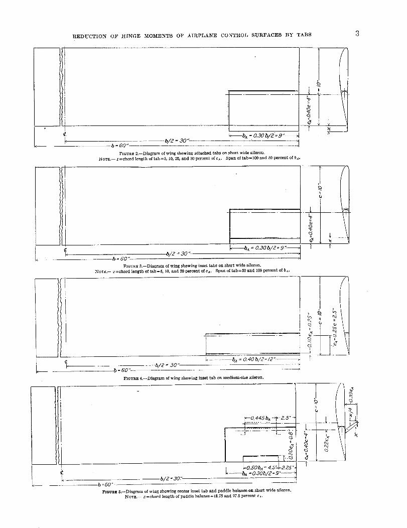
aileron was mounted on a different wing.Attached tabs.--The short wide aileron with
attached tabs is shown in figure 2. In the following
table the various attached tab arrangements are listed:
Tab chord Tab span
Percent c a Percent b a5 .................................. iO0
10 ................................. 100
10020............................... 50
5O5O
30 ................................. , 100I
Span designation
Full-span.
Outboard]Center }Half-span.Inboard ]Full-span.
Where c a is the chord and ba the span of the aileron.
"Outboard" refers to outboard end of tab flush with
outboard end of aileron, "center" refers to tab sym-
metrically located with respect to aileron span, and"inboard" refers to inboard end of tab flush with
inboard end of aileron.
The attached tabs were constructed of _%-inch flat
steel and were screwed to a brass trailing-edge pieceof the aileron so that when neutral the lower surface ofthe tab was flush with the lower surface of the aileron.
The angle of the tab was adjusted by bending aboutthe trailing edge of the aileron and all openings between
tab and aileron were sealed with plasticine.Inset tabs.--The short wide aileron is shown
equipped with inset tabs in figure 3. In the followingtable the various inset tab arrangements are listed:
Tab chord
Percent e A5 .................................
10.................................
'20 .................................
Tab span
Percent b a100100100
5O505O
Span designation
Full-span.
Outboard /Center }Half-span.Inboard ]
Outboard, center, and inboard have the same mean-
ing as for the attached tabs. The brass inset tabs wereattached to the main part of the aileron by soft wire
pins that could be bent to obtain the desired tabdeflections.
The medium-size aileron (fig. 4) was tested with a
tab extending along the entire span of the aileron and
with a chord 10 percent of the aileron chord. The,lileron was constructed of wood with a brass trailing
edge to which the brass tab was secured in a mannersimilar to that used for the inset tabs on the short wide
aileron. For all tests the space between tlle tab and
aileron was sealed with plasticine.Combination balanees.--Additional tests were made
at the request of the Bureau of Aeronautics, Navy
Department, of the short wide aileron and a ce#),er
inset tab 20 percent of the aileron chord wide and
half of the aileron span long in combination with two
sizes of paddles. The paddies were 18.75 and 27.5percent of the aileron chord wide and 44.5 percent of
the aileron span long and were located symmetricallywith respect to the aileron span (fig. 5). The duralu-
REDUCTION OF HINGE MOMENTS OF AIRPLANE CONTROL SURFACES BY TABS 3
b = GO"
L-_----b,_= o.3ob/2=S "-_
FIGURE 2.--Diagram of wing showing attached tabs on short wide aileron.
NowE.-- xfehord length of tab=5,10, 20, and3Opercentofca. Span of tab=100 and 50 percent of hA.
Ik
g[!l:
__.. v[
c_
II
b/2 = 30" "_.b = GO "
FIGURE 3.--Diagram of wing showing inset tabs on short wide aileron,
NOTE.-- z=chord length of tab=5, 10, and 20 percent of cA. Span of tab=50 and 100 percent of hA.
k----b A = 0.40b/2=12"- -_J
5/2 = ao"•b = 60 "
11
f
a
b : 60" --
FIGURE 4.--Diagram of wing showing inset tab on medium-size aileron.
_._-0. 445 bA -:'1"- 2. 5 ....
II g
| 2k--a,_ =0.30b/2= 9 "-
b/g = 30Y
FIGURE 5.--Diagram of wing showing center inset tab and paddle balance on short wide aileron.
NOTE.-- x=chord length of paddle balance=18.75 and 27.5 percent cA.
.
i
I
t
m_c_
k
4 :REPORT NATIONAL ADVISORY'COMMITTEE FOR AERONAUTICS
ii
L ¢L.
b =60"b/2 = 30".
^
_. .,._,_,!__ 1_,', 15oh i - L
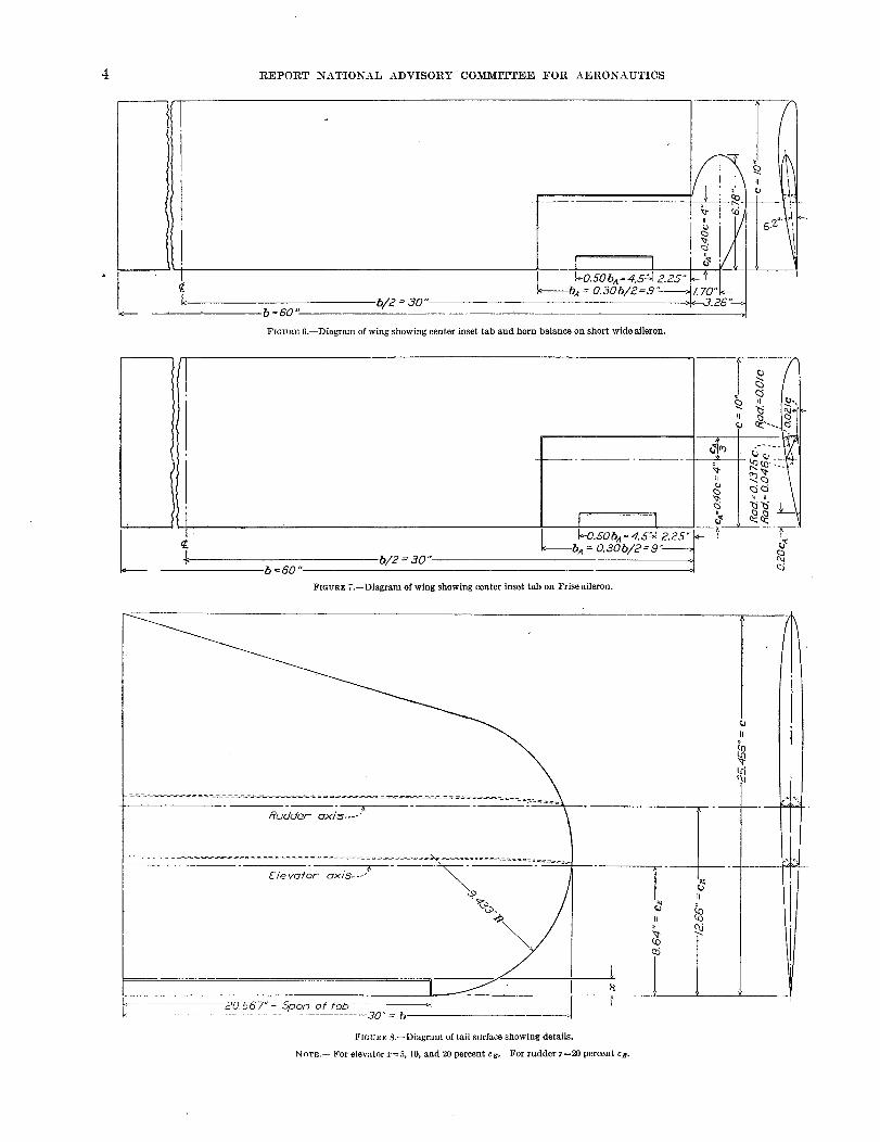
FIGURE 6.--Diagram of wing showing center inset tab and horn balance on short wide aileron.
!°/
- - :_ r_ _-__-0.SObA=4.5'c'J 225"_- _
_--bA = 0.306/2= 9'5"-- _ _•b = 60 "
b/2 = 30"
FIGURE7.--Diagram of wing showing center inset tab on Frise aileron.
20.567 "= Spore of fob................................ 30" = b
Fmua_: $.--Diagram of tail surface showing details.
NOT_.-- For elevator x=5, 10, and 20 percent cg. For rudder _'=20 percent c_.
II
REDUCTION OF HINGE MOMENTS OF AIRPLANE CONTROL SURFACES BY TABS.
min paddles had the N. A. C. A. 0012 profile and were
supported in the positions specified with _2-inchsheet steel end brackets.
On this same aileron a horn was attached for addi-
tional tests. The aileron was faired to a symmetrical
section in the horn, the principal dimensions of which
are shown in figure 6. The plan of the horn was made
to conform to the shape suggested by the Bureau of
Aeronautics, Navy Department, the leading-edge
portion being half of an ellipse. The horn was con-struct'ed of laminated mahogany and was fair to the
same precision as the remainder of the model.The short wide aileron was also tested with a
modified FHse type of balance and a tab (fig. 7).
The nose shape of the aileron was obtained from a
study of available Frise aileron data and was madesimilar to the Frise aileron of reference 9 with a raised
nose. This type of Frise balance gives slightly lessbalance for low deflections, where overbalance usually
occurs, but gives about the same balance as theordinary Frise aileron at the high deflections. The
mahogany nosepiece was attached to the leading
edge of the ordinary aileron by screws and a suitablecut-out was made in the wing to provide clearance.
(See fig. 7.)TAIL-SURFACE ARRANGEMENTS
The tail-surface model used in these tests is shown
in figure 8. The model of laminated mahogany hadan N. A. C. A. 0006 profile faired to about a ys-inch
radius at the tip and was constructed to a precision
of ±0.005 inch. The plan form of the model was
designed to be an average of either a half-span hori-zontal or a fifll-span vertical tail. The span of themodel was 30 inches and the average chord 20 inches,
giving an aspect ratio of 1.5. As a horizontal tail,
a portion of the model was hinged along the elevatoraxis shown in the figure. This arrangement gave an
elevator area 40 percent of the total tail area. Theinset tabs of different chord lengths were made with
a span equal to the span of the straight trailing-edge
portion of the elevator. The tab chords tested were5, 10, and 20 percent of the maximum elevator chord.The tabs were made from the trailing-edge portion of
the elevator and were secured to the main part of the
elevator by soft wire pins that could be bent to givethe desired tab deflections. As a vertical tail, 60
percent of the area of the model was hinged along the
rudder axis as shown in figure 8. Only one tab was
used; it had the same span as the elevator tab and a
chord 20 percent of the maximum rudder chord. Inall cases the gap between the tab and the tail surface
was sealed with plasticine.
WIND TUNNEL AND BALANCES
The N. A. C. A. 7-by 10-foot wind tunnel in
which these tests were made has an open jet and a
closed return passage. The tunnel and regular six-
component balance are described in detail in reference10. On this balance the six components of aerody-namic forces and moments are independently and
simultaneously measured with respect to the wind axesof the model.
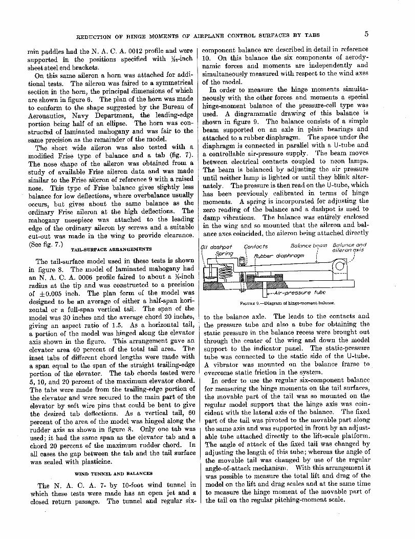
In order to measure the hinge moments simulta-
neously with the other forces and moments a special
hinge-moment balance of the pressure-cell type wasused. A diagrammatic drawing of this balance is
shown in figure 9. The balance consists of a simple
beam supported on an axle in plain bearings andattached to a rubber diaphragm. The space under t_m
diaphragm is connected in parallel with a U-tube and
a controllable air-pressure supply. The beam movesbetween electrical contacts coupled to neon lamps.
The beam is balanced by adjusting the air pressure
until neither lamp is lighted or until they blink alter-
nately. The pressure is then read on the U-tube, whichhas been previously calibrated in terms of hinge
moments. A spring is incorporated for adjusting the
zero reading of the balance and a dashpot is used to
damp vibrations. The balance was entirely enclosedin the wing and so mounted that the aileron and bal-ance axes coincided, the aileron being attached directly
7il do3hpof Confocfs Be/once beorn Bolonce ond
, . ] ,
I|IN ..........LJ_--A ir -pressure
oileron 9x/5w
fube
FIOURE 9.--Diagram of hinge-moment balance.
to the balance axle. The leads to tim contacts and
the pressure tube and also a tube for obtaining the
static pressure in the balance recess were brought outthrough the center of the wing and down the model
support to the indicator panel. The static-pressuretube was connected to the static side of the U-tube.A vibrator was mounted on the balance frame to
overcome static friction in the system.In order to use the regular six-component balance
for measuring the hinge moments on the tail surfaces,
the movable part of the tail was so mounted on the
regular model support that the hinge axis was coin-cident with the lateral axis of the balance. The fixed
part of the tail was pivoted to the movable part alongthe same axis and was supported in front by an adjust-able tube attached directly to the lift-scale platform.
The angle of attack of the fixed tail was changed by
adjusting the length of this tube; whereas the angle ofthe movable tail was changed by use of the regular
angle-of-attack mechanism. With this arrangement itwas possible to measure the total lift and drag of themodel on the lift and drag scales and at the same time
to measure the hinge moment of the movable part of
the tail on the regular pitching-moment scale.
6 REPORT NATIONAL ADVISORY COMMITTEE FOR AERONAUTICS
A reflection plane, which was used in conjunction
with part of the tail-surface tests, was constructed of_-inch plywood. It extended across the air stream
from top to bottom and from a point 7 inches upstream
from the leading edge of the model to 4 feet down-
stream from this point. The gap between the model
and the reflection plane was approximately _-inch.A telltale light was used to indicate any contact of
the reflection plane with the model.
TESTS
All tests were made at a dynamic pressure of 16.37
pounds per square foot, corresponding to an air velocityof 80 miles per hour at standard sea-level atmospheric
conditions. Thus, for the wing-aileron tests the aver-
age Reynolds Number was 609,000 and for the tail-
surface tests it was 1,218,000.
Wing-aileron arrangements.--Most of the tests ofthe wing-aileron arrangements were made at 0 °, 10 °,
15 °, and 20 ° angle of attack and at 0 ° yaw. For the
aileron deflections of 0 °, --15 °, and --30 °, the tab was
deflected 0°, 10 °, 20 °, 30 °, and 40 °, and for ailerondeflections of 0 °, 15 °, and 30 °, the tab was deflected 0°,
--10 °, --20 °, --30 °, and --40 °. In the aileron tests
with the paddles, horn, and Frise types of balance thetab deflections were limited to 0 °, =t=10°, ±20 °, and
=k30 ° because previous tests had shown that the 40 °
deflections gave less reduction in hinge moment thanthe 30 ° deflections. Tests were made on the model
with the Frise aileron at both 0 ° and 20 ° yaw to deter-
mine the effect of yaw on the balance of ailerons with
tabs. It is believed that the foregoing range of aileron
deflections covers the range used on present-dayairplanes. In every case a positive deflection means
that the trailing edge of the deflected surface moved
below its neutral position.
Tall-surface arrangements.--After installation of thereflection plane in the tunnel, dynamic-pressure sur-
veys were made before the tail-surface model was put
in place and the reference static pressure was recali-brated for the interference effects. The reflection
plane was used in all the tests with the horizontal tail
because this arrangement was thought to be more
nearly representative of the majority of present-daytail installations. In these tests the stabilizer angles
as used were --10 °, --5 °, 0 °, 5°, and 10% For each
stabilizer angle the elevator was deflected 0°, --10 °,--20 °, and --30 ° from the stabilizer. The 5- and
10-percent-chord tabs were deflected 0 °, 10°, ' 20 °, and
30 ° for each elevator setting and the 20-percent-chordtab was also deflected 40 ° because it was sometimes
more effective at the high deflections.The vertical tail was tested both with and without
the reflection plane in place. The tests were madewith the fin angles _ of --10 °, --5 °, 0 °, 5 °, and 10°.
For each fin setting the rudder was deflected 0 °, 10°,
20 ° , and 30 ° from the fin and for each rudder setting
the tab was deflected 0°, --10 °, --20 °, and --30 ° from
the rudder. A positive deflection is to the left as seenfrom the rear.
RESULTS
WING-AILERON ARRANGEMENTS
The results of the tests on the wing-aileron arrange-ments are given in terms of the following nondimen-sional coefficients:
Ca lift
CD drag
C{ rolling momentqbS , wind axis
C ' yawing momentn =" qbS , wind axis
Chl hinge moment,-_ qCA2ba aileron axis
where q is dynamic pressure.
S, area of wing (not including attached tabs, pad-dles, or horns).
b, span of wing (not including horn).cA, chord of aileron (not including attached tabs,
horns, or Frise balance area).ba, span of aileron (not including horn).
The values of CL, CD, Ct', and C_' are read directly on
the balances and are comparable for the different ar-
rangements. It should be noted that, with the hinge-moment coefficient based on the dimensions of the
aileron to which they apply, comparisons of differentvalues of C_, for different conditions of any given aile-ron are valid, but comparisons between hinge-momentcoefficients for different ailerons cannot be made sim-
ply by comparing values of Ch,. If such a comparisonis desired, it will be necessary to recalculate the hingemoments on the basis of some common dimension.
The complete data are presented in tabular form.
In table I, CL and CD for all the arrangements are
listed. The change in lift and drag caused by theattached tabs was within the experimental accuracy
of the tests. The data for the tests with the paddies,
horn, and Frise aileron have been corrected for onearrangement on each wing tip. The values of C{, C=',
and Ch, for the attached tabs on the short wide aileron
are tabulated as follows: The full-span tabs of different
chords in table II and the 20 percent ca half-span tabat the several locations along the aileron span in
table III. The corresponding data for the inset tab
on this aileron are given in tables IV and V. Thedata for the medium-size aileron with the 10 percent
ca full-span inset tab are given in table VI. In table
VII the corresponding data are given for the shortwide aileron with the 20 percent ca half-span center
inset tab in combination with the paddle, horn, and
REDUCTION" OF HII_GE MOMENTS OF AIRPLANE CONTROL SURFACES BY TABS
Frise types of balance. The data for the Frise aileron
when yawed 20 ° are also given in table VII. Itshould be noted that the rolling- and yawing-momentcoefficients with the ailerons and tabs undeflected are
those due to yaw alone; whereas for the tests in which
they were deflected the moment coefficients are dueto tab or aileron.
In order to obtain the results for two ailerons, one
on the right tip and one on the left, it is necessary tochange the signs of the data for the down aileron and
add.. (See reference 11.) By use of this convention
in summing up the results for two ailerons the signswill be plus when C_ t is in the desired direction and
when C, _ aids the roll. The value of Ca, _ll be plus
when it requires a force to move the stick to obtain
larger aileron deflections and minus when the aileronsare overbalanced.
TAIL-SURFACE ARRANGEMENTS
The results of the tests on the tail surfaces are given
in the form of the following vondimensional coeffi-cients:
G --n°rmal forceN-- _St
hinge moment
Cnl= q(c_.2 or cR°,2)(bE or b_)
where St, total area of tail surface.
cBo. or ca°., average chord of elevator or rudder.
bB or bR, maximum span of elevator or rudder.
The value of Gx was computed from the lift and drag
coefficients as measured and Chx was computed from
the pitching-moment scMe readings. The data astabulated are for negative fixed tail settings with
various plus and minus elevator or rudder settings
and the corresponding minus and plus tab settings.
The complete data for the various chord tabs on the
elevator are given in table VIII and for the 20 per-cent ca tab on the rudder both with and without the
reflection plane in table IX.
PRECISION
The coefficients C,., CD, and GN are correct to within
± 3 percent and coefficients CL and C_ t are, in general,
correct to within ±3 percent except at 20 ° angle of
attack. The value of Chl is correct to within ±3
percent for the ailerons, ±5 percent for the elevator,
and ± 2 percent for the rudder.
DISCUSSION
METHOD OF COMPARING TABS
In a comparison of the results of tests on tabs it isnot sufficient to compare merely the reductions in
hinge moments because tabs not only reduce thehinge moment but at the same time reduce the effec-tiveness of the control surface. A criterion for the
comparison of different arrangements of tabs and140293---35--2
7
control surfaces should therefore take into account
hinge moment, control deflection," the moment pro-
duced by the control surface, and the air speed. For
the comparisons made herein, the simple criterionsCzr or C_ were chosen for control effectiveness and
Ghx8 for control force. These criterions do not take
into account changes in air speed but are valid for
making comparisons at any given angle of attack.Other things being equal, however, the higher the air
speed the higher the control force, and vice versa.The control-force criterion also assumes that the stick
or rudder bar moves equal amounts for equal values
of Cz' or CN, respectively, the linkage between thestick and control surface being changed accordingly.
Therefore, even though Ch1 may be reduced consider-
ably, if it is necessary to move the control surfacethrough a very large angle, the product Chl_ may be
fx I
J J _
-_j . .J J _
-0 ° x " 6r 0 °
- I0 ° o ...... I0 °"-20 ° o-- --20 °
" -30 ° a .... 30 °--40 ° + ......... 40 °
--_;__. _-- _
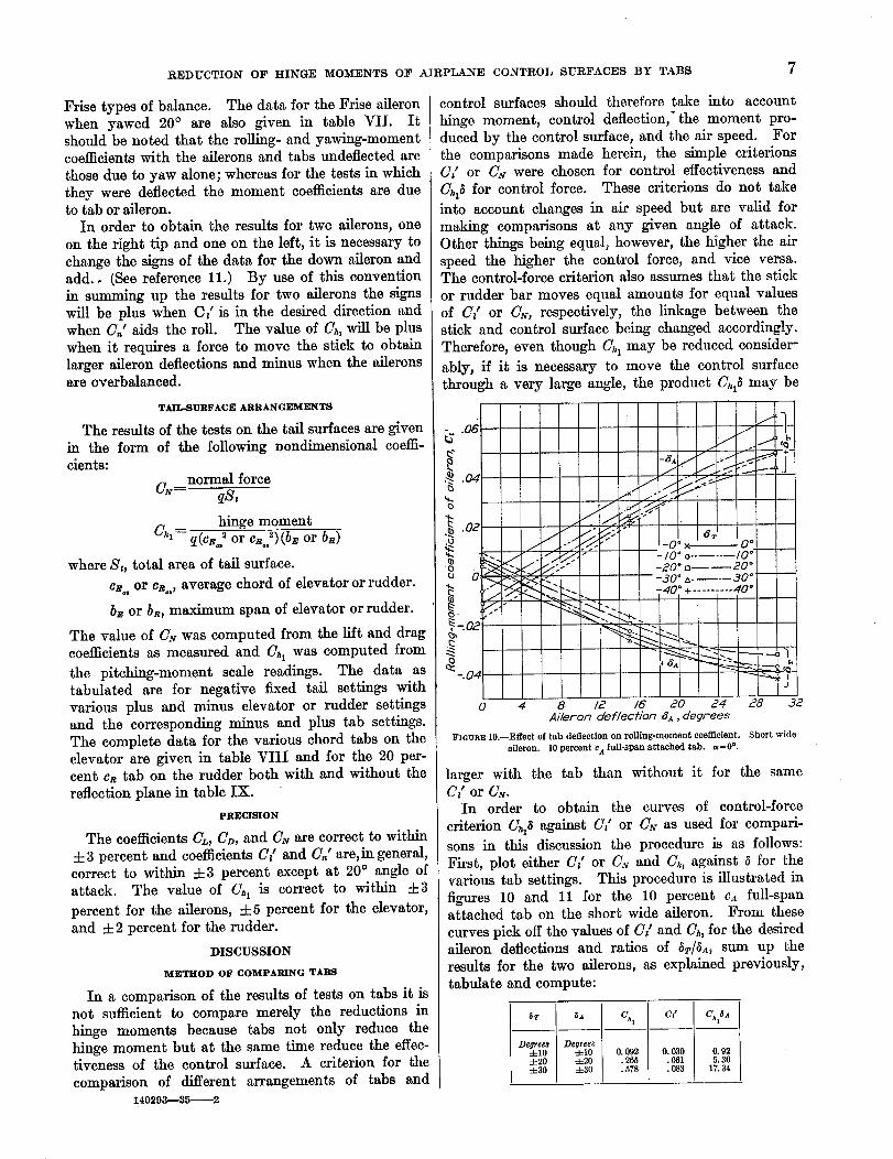
0 4 8 /2 16 20 24 28 d2AHeron deflection 8_, degrees
FIGURE 10.--Effect of tab deflection on rolling-moment coefficient. Short wide
aileron. 10 percent c_ full-span attached tab. a=0 °.
larger with the tab than without it for the same
CL or CN.In order to obtain the curves of control-force
criterion C_ against C_' or C_ as used for compari-sons in this discussion the procedure is as follows:
First, plot either CL or C.v and Ch, against 6 for thevarious tab settings. This procedure is illustrated in
figures 10 and 11 for the 10 percent ca full-spanattached tab on the short wide aileron. From these
curves pick off the values of C[ and C_, for the desiredaileron deflections and ratios of _r/_._, sum up theresults for the two ailerons, as explained previously,
tabulate and compute:
_r _ C,. x C_' c_,_
Degrees Degree._-4-10 4-10 0. 092 0. 030 0. 92
4-20 4-20 .265 .061 5.30
4-30 4-30 . 578 . 083 17. 34
8 REPORT NATIONAL ADVISORY COMMITTEE FOR AERONAUTICS
The example given is for an equal up-and-downaileron movement and for _r/_a--1.0. The best ratio
of 8r/_A for a given size of tab can be obtained by
maldng the computations as outlined for several
ratios of _r/SA and then plotting Ch, _A against C/andpicking the best ratio from this plot. In order to
find the optimum size of tab for a given ratio of
_r/_A, the same computations should be made forseveral sizes of tabs.
The effectiveness of a tab in trimming the aircraft
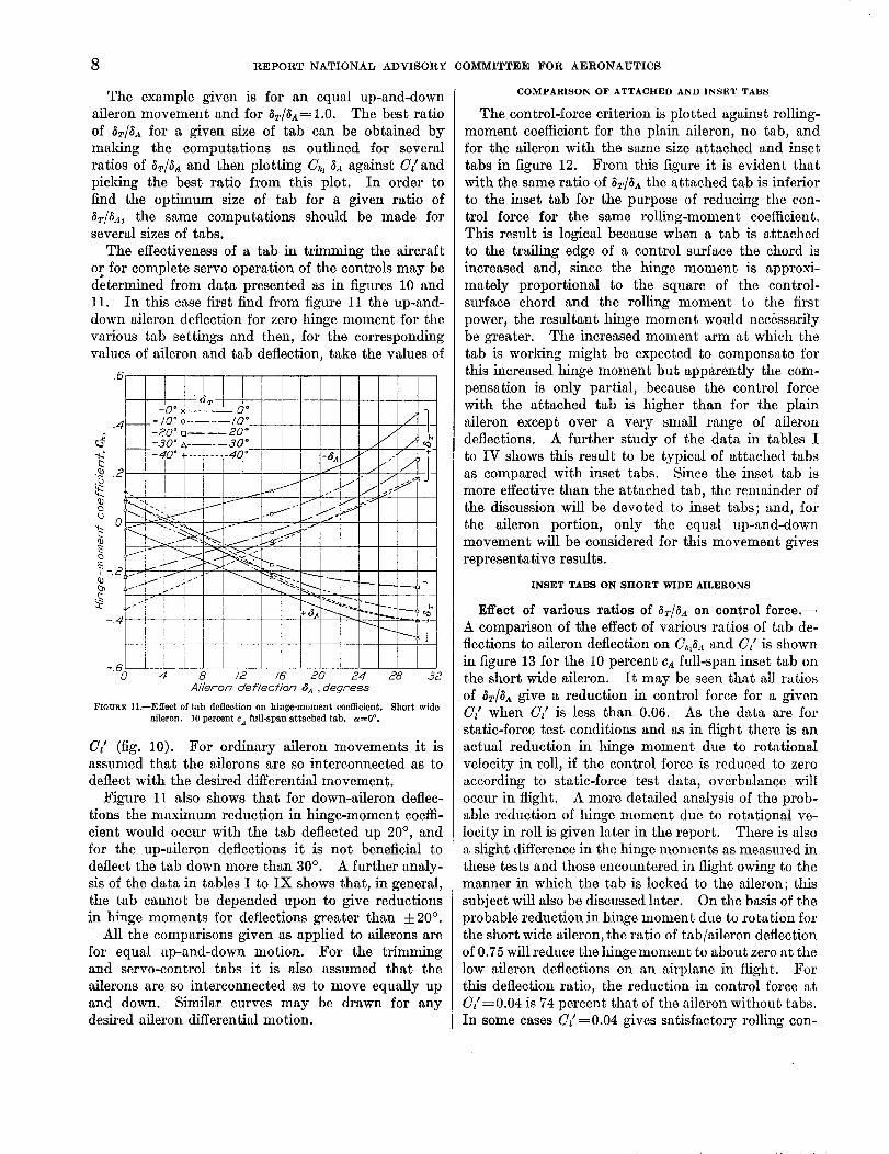
or for complete serve operation of the controls may bedetermined from data presented as in figures 10 and11. In this case first find from figure 11 the up-and-
down aileron deflection for zero lfinge moment for the
various tab settings and then, for the correspondingvalues of aileron and tab deflection, take the values of
.4 __L-/0 ° o ...... /O °_-20 ° _----20 °
_3 --_-30" z_.... 30 °_
-_ -40 ° _-........ 40"!
u 0 i _t
o /
-.4
0 4
I_2_
//
J_x _
/'
.-4
._1.__ _ :...-_ __
I
8 /2 /6" 20
Ai/eron def/ection _.4 , degrees
"/ 1-/
. i +-
J i'/jf _
y
24 28 ,32
FIGURE ll.--Effect of tab deflection on hinge-moment coefficient. Short wide
aileron. I0 percent ca full-span attached tab. a=0 °.
C/ (fig. 10). For ordinary aileron movements it isassumed that the ailerons are so interconnected as todeflect with the desired differential movement.
Figure 11 also shows that for down-aileron deflec-
tions the maximum reduction in hinge-moment coeffi-
cient would occur with the tab deflected up 20 ° , andfor the up-aileron deflections it is not beneficial to
deflect the tab down more than 30 °. A further analy-
sis of the data in tables I to IX shows that, in general,
the tab cannot be depended upon to give reductionsin hinge moments for deflections greater than ±20 °.
All the comparisons given as applied to ailerons are
for equal up-and-down motion. For the trimmingand serve-control tabs it is also assumed that the
ailerons are so interconnected as to move equally up
and down. Similar curves may be drawn for anydesired aileron differential motion.
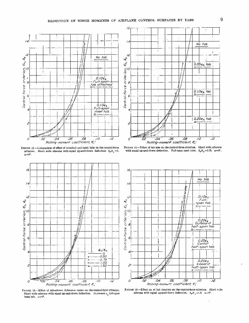
COMPARISON OF ATTACHED AND INSET TABS
The control-force criterion is plotted against rolling-
moment coefficient for the plain aileron, no tab, andfor the aileron with the same size attached and inset
tabs in figure 12. From tiffs figure it is evident thatwith the same ratio of 8r/SA the attached tab is inferior
to the inset tab for the purpose of reducing the con-
trol force for the same rolling-moment coefficient.This result is logical because when a tab is attached
to the trailing edge of a control surface the chord is
increased and, since the hinge moment is approxi-
mately proportional to the square of the control-surface chord and the rolling moment to the first
power, the resultant lfinge moment would necessarily
be greater. The increased moment arm at which thetab is worldng might be expected to compensate for
this increased hinge moment but apparently the com-
pensation is only partial, because the control force
with the attached tab is higher than for the plain
aileron except over a very small range of ailerondeflections. A further study of the data in tables I
to IV shows this result to be typical of attached tabs
as compared with inset tabs. Since the inset tab ismore effective than the attached tab, the remainder of
the discussion will be devoted to inset tabs; and, for
the aileron portion, only the equal up-and-down
movement will be considered for this movement givesrepresentative results.
INSET TABS ON SHORT WIDE AILERONS
Effect of various ratios of _r/_a on control force.--
A comparison of the effect of various ratios of tab de-
flections to aileron deflection on Ch,_._ and C/is shownin figure 13 for the 10 percent ca full-span inset tab on
the short wide aileron. It may be seen that all ratios
of 5r/_ give a reduction in control force for a givenC/ when C/ is less than 0.06. As the data are for
static-force test conditions and as in flight there is an
actual reduction in hinge moment due to rotational
velocity in roll, if the control force is reduced to zero
according to static-force test data, overbalance will
occur in flight. A more detailed analysis of the prob-able reduction of hinge moment due to rotational ve-
locity in roll is given later in the report. There is also,_ slight difference in the hinge montents as measured in
these tests and those encountered in flight owing to the
manner in which the tab is locked to the aileron; this
subject will also be discussed later. On the basis of theprobable reduction in hinge moment due to rotation for
the short wide aileron, the ratio of tab/aileron deflection
of 0.75 will reduce the hinge moment to about zero at the
low aileron deflections on an airplane in flight. Forthis deflection ratio, the reduction in control force at
C/=0.04 is 74 percent that of the aileron without tabs.
In some cases C/=0.04 gives satisfactory rolling con-
REDUCTION" OF HINGE MOMENTS OF AIRPLANE CONTROL SURFACES BY TABS 9
/4
/2
_Y_/0
_8
k.
.k 6Cl
(3
, /II I No tab
l O.IOCAFu //-spon -t--fob off'ached
_/n// Fu /l- s p on _ __
/,//; _nsef fob0
JIlii
0 .02 .04 .06 .08 ./0 ./2
Rolling-momenf coefficienf, Cz'
FIeURR t2.--Comparison of effect of attached and inset tabs on the control-foice
criterion. Short wide ailerons with equal up-and-down deflection 8rD.t =I,a=0 o.
/G
l No fob
_/ O.05cA fob
0
,f"_ O. I OeA rob
[]
Y
0.2OCA
fo6
, A ..... "---7-
0 .02 .04 .06 .08 .10 .12
Ro///ng-momenf coeff/c/en¢, C_'
FIGURE 14.--Effect of tab size on the control-force criterion. Short wide ailerons
with equal up-and-down deflection. Full-span inset tabs. 8r/$A=0.75. a=O °.
/6
.......
/4 ........
j" II-4
i
k. -- --
24 /' 8r/SA __-0
+ ..... 0.50
//,,,,--f/ -x.... 075o---- 1.00
.... ,,o....0 __.02_ .04 .06 .OB ./0 .12
Rolling-momenf coeff/v/_'n_ C_'
FIGURE 13.--Effect of tab-aileron deflection ratios on the control-force criterion.
Short wide ailerons with equal up-and-down deflection. 10 percent cA full-spaninset tab, a=O °.
O. lOG4 --
Full-
Soon rob __O------
0.20cAOufboord _ __
i holf-spoo fob
,_ o. t
0 20CA
Cenfer- __holf-3pon fob
.... , zx........ i ....
_ o._o_____ /nboor-d .__
y holf-spon fob
0 02 .04 .OG .08 .10 .12
Ro//,,n_-momenf coeff/c/'en:/;, Cz"
FIGURE 15.--Effect on of tab location on the control-force criterion. Short wide
ailerons with equal up-and-down deflection. 5r/SA=l.O. a=O °.
10 REPORT NATIONAL ADVISORY COMMITTEE FOR ¢_ERONAUTICS
trol. (See reference 12.) If a value of G/=0.075 is
necessary for satisfactory control, none of the tabs arebeneficial for the extreme control-surface movements.
For the high-speed condition of flight the tab is quite
satisfactory, however, as a means of balance. For the
ratio of _r/_A = 1.0 overbalance would probably occur in
flight owing to the reduction of hinge moment causedby the rolling velocity; for the ratio 1.5 overbalanceoccurs in the wind-tunnel tests.
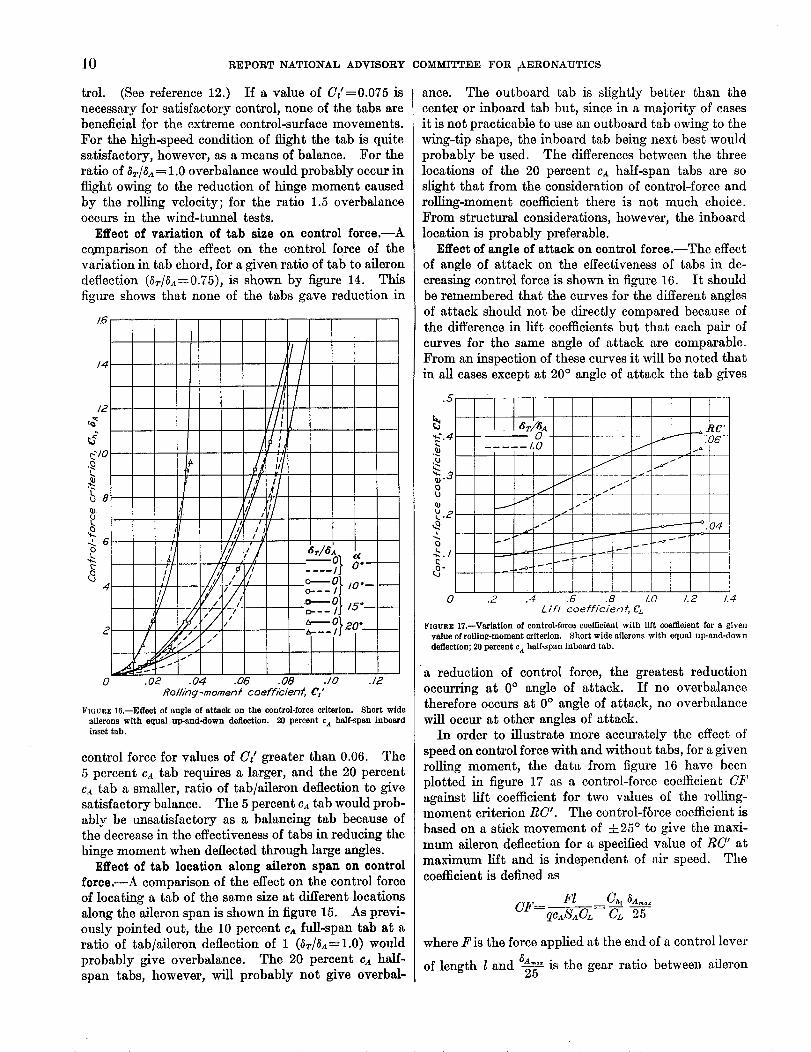
Effect of variation of tab size on control force.--A
comparison of the effect on the control force of thevariation in tab chord, for a given ratio of tab to aileron
deflection (_r/SA----0.75), is shown by figure 14. This
figure shows that none of the tabs gave reduction in
/6
I
4/z I
C/o
bo
_oe / ,'
ill /J'
. , 2,2/"
/ 2".£:".02 .04
__-___}o'---
,o.__,.___
7-__0,}.°.___
0 .06 .08 .10 .12
Roiling-moment coeffidenf, C'z"
FIGURE 16.--Effect of angle of attack on the control-force criterion. Short wide
ailerons with equal up-and-down deflection. 20 percent ca half-span inboardinset tab.
control force for values of C/greater than 0.06. The
5 percent ca tab requires a larger, and the 20 percentca tab a smaller, ratio of tab/aileron deflection to give
satisfactory balance. The 5 percent CA tab would prob-
ably be unsatisfactory as a balancing tab because ofthe decrease in the effectiveness of tabs in reducing the
hinge moment when deflected through large angles.
Effect of tab location along aileron span on controlforce.--A comparison of the effect on the control force
of locating a tab of the same size at different locations
along the aileron span is shown in figure 15. As previ-ously pointed out, the 10 percent Ca full-span tab at a
ratio of tab/aileron deflection of 1 (Sv/Sa= 1.0) would
probably give overbalance. The 20 percent ca half-
span tabs, however, will probably not give overbal-
ance. The outboard tab is slightly better than the
center or inboard tab but, since in a majority of casesit is not practicable to use an outboard tab owing to the
wing-tip shape, the inboard tab being next best would
probably be used. The differences between the three
locations of the 20 percent ca half-span tabs are soslight that from the consideration of control-force and
rolling-moment coefficient there is not much choice.
From structural considerations, however, the inboard
location is probably preferable.
Effect of angle of attack on control force.--The effectof angle of attack on the effectiveness of tabs in de-
creasing control force is shown in figure 16. It should
be remembered that the curves for the different angles
of attack should not be directly compared because ofthe difference in lift coefficients but that each pair of
curves for the same angle of attack are comparable.
From an inspection of these curves it will be noted that
in all cases except at 20 ° angle of attack the tab gives
.5
8
L, r
- J --
.2 .4
! 4'"o" ii II I
•G .8 1.0 1.2 1.4
Lift coefficient, Cz.
FIGUR_eit--Variation of control-force coefficient with lift coefficient for a givenvalueofrolling-moment criterion. Short wide ailerons with equal up-and-down
deflection; 20 percent eA half-span inboard tab.
a reduction of control force, the greatest reduction
occurring at 0° angle of attack. If no overbalancetherefore occurs at 0 ° angle of attack, no overbalance
will occur at other angles of attack.
In order to illustrate more accurately the effect of
speed on control force with and without tabs, for a givenrolling moment, the data from figure 16 have been
plotted in figure 17 as a control-force coefficient CF
against lift coefficient for two values of the rolling-moment criterion RC'. The control-fbrce coefficient is
based on a stick movement of ±25 ° to give the maxi-
mum aileron deflection for a specified value of RC' atmaximum lift and is independent of air speed. The
coefficient is defined as
Fl CA, 8a.o.CE:--qc[S_CL= -_L _
where F is the force applied at the end of a control lever
l and _ is the gear ratio between aileronof length
REDUCTION OF HINGE MOMENTS OF AIRPLANE CONTROL SURFACES BY TABS 11
and control lever. The rolling-moment criterion is
RC =C/ICL
which is proportional to the rolling moment in foot-pounds and is also independent of air speed.
Inspection of these curves shows that the controlforce is reduced by the use of tabs nearly the sameabsolute amount for any given RC', regardless of liftcoefficient, and that the greatest percentage reductionoccurs at the low values of RC' and at low lift coeffi-
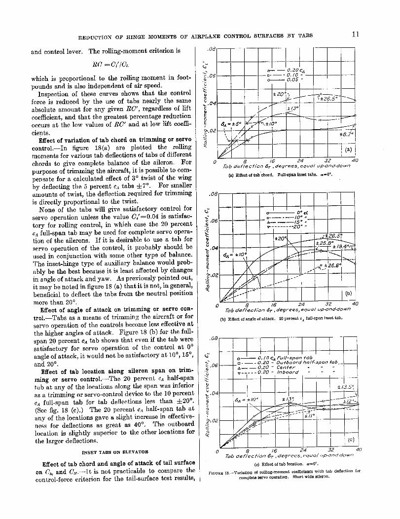
cients.Effect of variation of tab chord on trimming or servo
control.--In figure 18(a) are plotted the rollingmoments for various tab deflections of tabs of different
chords to give complete balance of the aileron. Forpurposes of trimming the aircraft, it is possible to com-pensate for a calculated effect of 3 ° twist of the wingby deflecting the 5 percent CA tabs 4-7 °. For smalleramounts of twist, the deflection required for trimmingis directly proportional to the twist.
None of the tabs will give satisfactory control for
servo operation unless the vahe C/=0.04 is satisfac-tory for rolling control, in which case the 20 percentc._ full-span tab may be used for complete servo opera-tion of the ailerons. If it is desirable to use a tab for
servo operation of the control, it probably should beused in conjunction with some other type of balance.The inset-hinge type of auxiliary balance would prob-ably be the best because it is least affected by changesin angle of attack and yaw. As previously pointed out,it may be noted in figure 18 (a) that it is not, in general,beneficial to deflect the tabs from the neutral positionmore than 20 °.
Effect of angle of attack on trimming or servo con-trol.--Tabs as a means of trimming the aircraft or for
servo operation of the controls become less effective atthe higher angles of attack. Figure 18 (b) for the frill-span 20 percent ca tab shows that even if the tab weresatisfactory for servo operation of the control at 0 °angle of attack, it would not be satisfactory at 10°, 15°,and 20° .
Effect of tab location along aileron span on trim-ruing or servo control.--The 20 percent cA half-spantt_b at any of the locations along the span was inferioras a trimming or servo-control device to the 10 percentca full-span tab for tab deflections less than 4-20 °.(See fig. 18 (c).) The 20 percent cx half-span tab atany of the locations gave a slight iDerease in effective-ness for deflections as great as 40 ° . The outboardlocation is slightly superior to the other locations for
the larger deflections.
INSET TABS ON ELEVATOR
Effect of tab chord and angle of attack of tail surfaceon Ch, and C_.--It is not practicable to compare thecontrol-force criterion for the tail-surface test results
.O8
C
.06
_ .04
0
__ -- o.2oc, tv- -o. 10 ,,o l-- o.05 "
±201-.
/ ±/3 °
6x =±5° =" '"elO°
8 16 247"oh deE/cob'on ¢5r , deqree._, equol up-ond-down
(a) Effect of tab'chord. Full-span inset tabs. ==O °.
f
/
_8.7'o
(a)
32 40
.04
OZ
o 0 ° d.m.... I0 ° "
----15 ° .v- ....... -20 ° "
I± o
• 20 _,
< "_f" 1 ""_ _:26"6°'-"/ .//. j�
... {b)
8 IG 24 32 40['o_ deflect�on _r , degrees, equo/ up-ond-down
(b) Effect of angle of attack. 20 percent ca full-span inset tab.
oa Ii
,OG --
.04
.02
/
IL Lql]o-- O. IO CA Full-span tab
- -- - 0.20 ,' OuCboorcl holE-_pon fob ___0
a-- -- 0.20 " Centerv ..... 0.20 " Inboard " "
I
6A = :_10_ ± 137
. _ £ II°
±/3.51!
.-----j2o
8 16 Z4 32Tob def/ec//On _r , deqreeS, equo/ up-onddown
(c) Effect of tab location, a=O °.
(c)
40
F_Gun_ 18.--Variation of rolling-moment coefficients with tab deflection forcomplete servo operation. Short wide aileron.
12 REPORT NATIONAL ADVISORY COMMITTEE FOR AERONAUTICS
(a)I
-LO -.8 -.6
-30 °
---:_--:: .... -
-]5° ,......
I=4 -=2 0
I
(c) as=--5 °. Postive deflection of elevator,
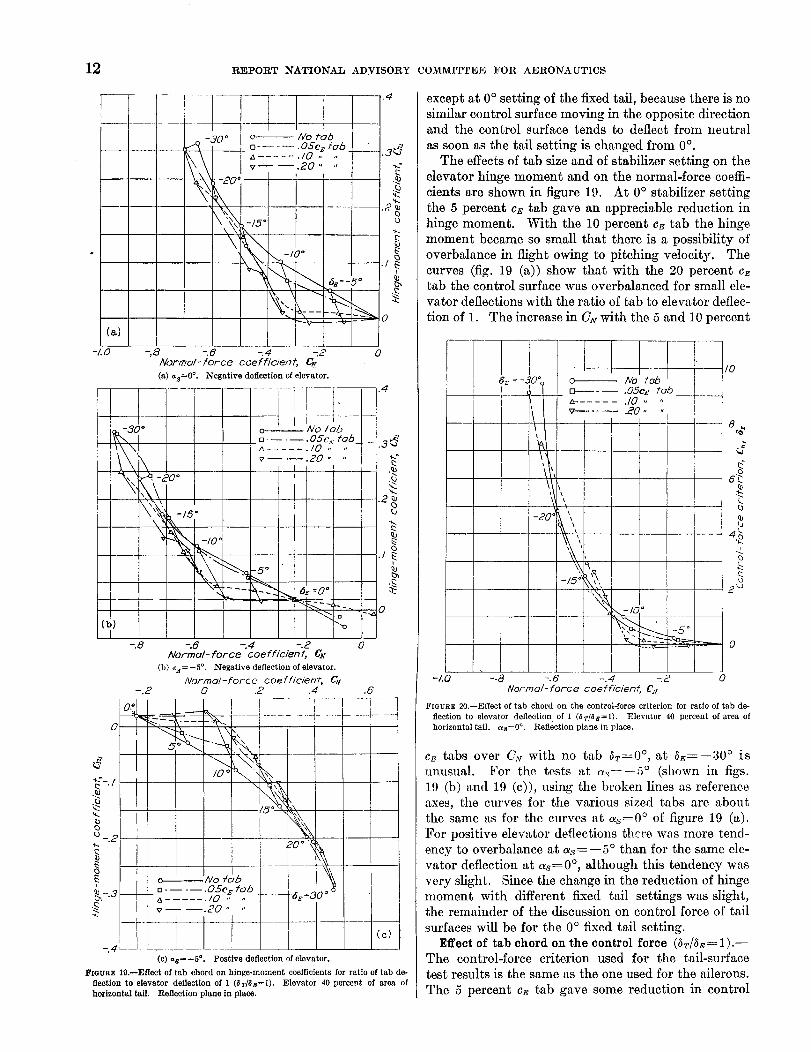
FIGURE 19.--Effect of tab chord on hinge-moment coefficients for ratio of tab de-flection to elevator deflection of 1 (aT/aE=l). Elevator 40 percent of area ofhorizontal taft. Reflection plane in place.
except at 0° setting of the fixed tail, because there is no
similar control surface moving in the opposite directionand the control surface tends to deflect from neutral
as soon as the tail setting is changed from 0%
The effects of tab size and of stabilizer setting on theelevator hinge moment and on the normM-force coeffi-
cients are shown in figure 19. At 0° stabilizer setting
the 5 percent cE tab gave an appreciable reduction inhinge moment. With the 10 percent cE tab the hinge
moment became so small that there is a possibility of
overbalance in flight owing to pitching velocity. The
curves (fig. 19 (a)) show that with the 20 percent cEtab the control surface was overbalanced for small ele-
vator deflections with the ratio of tab to elevator deflec-
tion of 1. The increase in C_ with the 5 and 10 percent
l-l-
I/
-z5"
o-------- No robu-----.05eE rob_- ..... ./0 ,,
-- -- 20 .... I
1
i
/0
8_
L
b
i
Q0
2 _
0
-/.0 -.8 -.6 -.4 -.2 O
Normo/-force coefficienf, #x
FmURB 20.--Effect of tab chord on the control-force criterion for ratio o£ tab de-
flection to elevator deflection of 1 (a_/a_=]). Elevator 40 percent of area ofhorizontal tail. as=0 °. Reflection plane in place.
c_ tabs over C,v with no tab at=0 °, at a_=--30 ° is
unusual. For the tests at a.,----5 ° (shown in figs.
19 (b) and 19 (c)), using the broken lines as reference
axes, the curves for the various sized tabs are aboutthe same as for the curves at as--0 ° of figure 19 (a).
For positive elev._tor deflections there was more tend-
ency to overbalance at as=--5 ° than for the same ele-vator deflection at as=0 °, although this tendency was
very slight. Since the change in the reduction of hinge
moment with different fixed tail settings was slight,the remainder of the discussion on control force of tail
surfaces will be for the 0 ° fixed tail setting.
Effect of tab chord on the control force (at/as= 1).-The control-force criterion used for the tail-surface
test results is the same as the one used for the ailerons.
The 5 percent c_ tab gave some reduction in control

REDUCTION OF HINGE MOMENTS OF AIRPLANE CONTROL SURFACES BY TABS13
force for all values of the normal-force coefficient.
(See fig. 20.) The 10 percent c_ tab gave reduction incontrol force only for normal-force coefficients less
than 0.44, although it will probably give overbalancefor small elevator deflections as pointed out previously.
The 20 percent cE tab gave overbalance in the static-force tests.
Effect of various ratios of _T/_ on control force.-
It may be seen (fig. 21) that the 20 percent c_ tabwith a deflection ratio of 2/3 gave approximately the
same'reduction as the 10 percent cE tab (fig. 20) witha deflection ratio of 1. None of the arrangements
gave satisfactory ballmce for normal-force coefficients
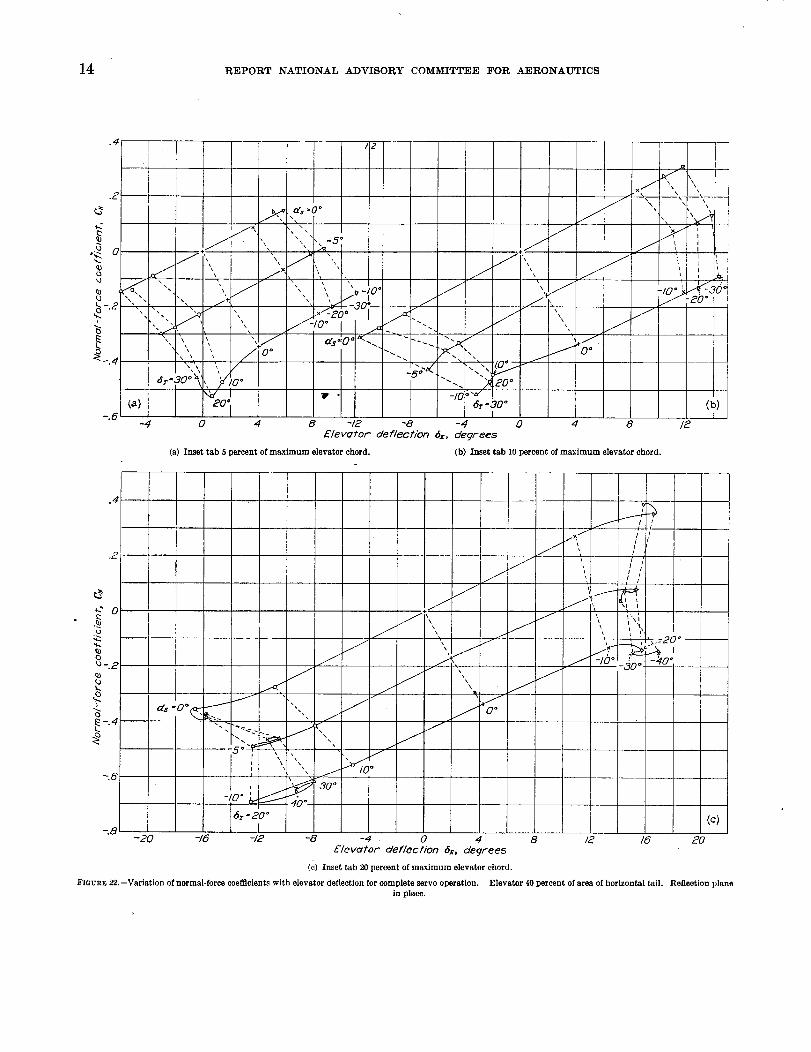
greater than about 0.40.Trimming or servo-control tab.--The results that
may be expected by using these tabs for trimming orservo operation of the elevator are shown in figure 22.
In this figure the normal-force coefficient and elevatordeflection are plotted for the condition of the elevator
completely balanced by the tab. These data may beused to determine the tab size and setting necessary
to balance the airplane if the angle of attack of thetail is known. It should be noted that no benefit
would be obtained by deflecting the tab to angles
greater than 20 ° to the elevator. As the maximum
change in C_ that could be obtained with the 0.20 eL.tab as a servo control is small, being equivalent to that
obtained with only a 10 ° deflection of the elevator
without tab, probably none of these tabs would be
satisfactory as a servo control unless used in conjunc-tion with some other type of auxiliary balance.
INSET TABS ON RUDDER
Tile rudder, as previously mentioned, w'ls tested
with only the 20 percent cR tab both with and withoutthe reflection plane. The vertical tail of most air-
planes is probably most nearly represented by the
arrangement without the reflection plane, althoughsome vertical tails would be approximated by the
conditions represented with the reflection plane. The
effect of the change in fixed tail setting on the results
having been discussed for the horizontal tail, the dis-cussion for the vertical tail will be limited to the 0 °
fin setting (¢F=0), except for trimming and servo-
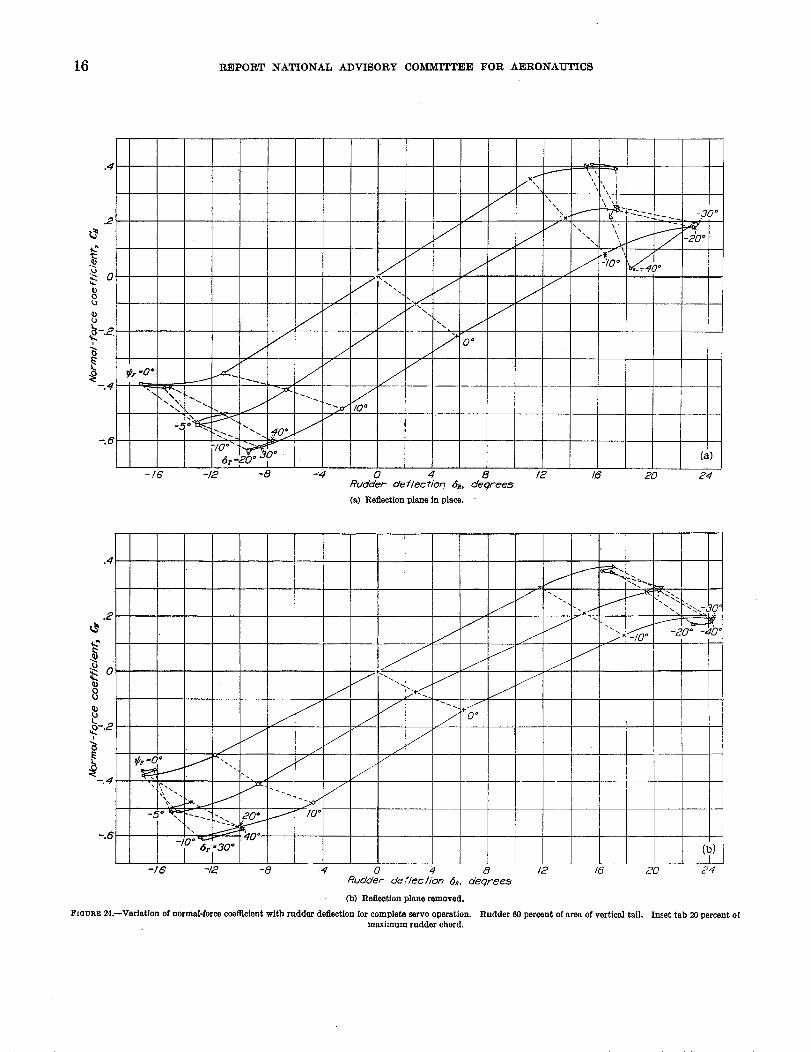
control tabs.Reduction of control force.--With the reflection
plane in place, the ratio of 8r/SR=2/3 gave verysatisfactory reduction in control force for small rudder
deflections, and some reduction for all values of C,vless than 0.63 (fig. 23 (a)). This tab/rudder deflection
ratio probably will not give any overbalance on anairplane due to yawing velocity in flight. For allvalues of C_ greater than 0.63 it would be better touse the control without the tab. For lfigher tab/rud-
der deflection ratios overbalance will occur at the low
deflections.
Without tile reflection plane (lig. 23 (b)) the control
force was higher for all values of the normal-force
coefficient than with the reflection plane. This in-creased control force was probably due to the smaller
effective aspect ratio of the model, which is accom-
panied by a lower slope of the lift curve, and also to
the large tip loads on the rectangular tip of the rudder.Insofar as balance is concerned, the tab/rudder deflec-
tion ratio of 2/3 is probably the largest that can beused without overbalance. The tab hi this case was
effective in reducing the control force only for valuesof normal-force coefficient less than 0.60, which is
approximately the same as for the model with the
reflection plane.Trimming or servo:control tab.--For trin_ming or
servo control the tab was about equally effective either
_- ..... dr/_ = 2/3 ----T-O--- " =1
1
/0
,Y
k0
ca
a_
(3
2
\20"
\
- / 5° '_,
II I ]
-ZO -.8 -.6 -.4 -.£ 0Nor'rno/- for'ce coefficienf, C_
FIGURE 21.--Effect of tab-elevator deflection ratios on the control-force criterion.Elevator 40 percent of area of horizontal tail. Inset tab 20 percent of maximumelevator chord, as=O °. Reflection plane in place.
with or without the reflection plane. (See fig. 24.)The maximum value of C_ was obtained with the tab
deflected only 20 ° and was 0.39 with the reflection
plane and 0.38 without it for the fin set at 0G,
(¢F---0°). This value of C_ corresponds to a rudder
displacement of about 10 ° without tab. The 20 ° tabdeflection is probably greater than necessary for trim-
ming but is not satisfactory for servo operation of thecontrol. For servo operation of the control, the tab
would have to be used in conjunction with some other
type of auxiliary balance.
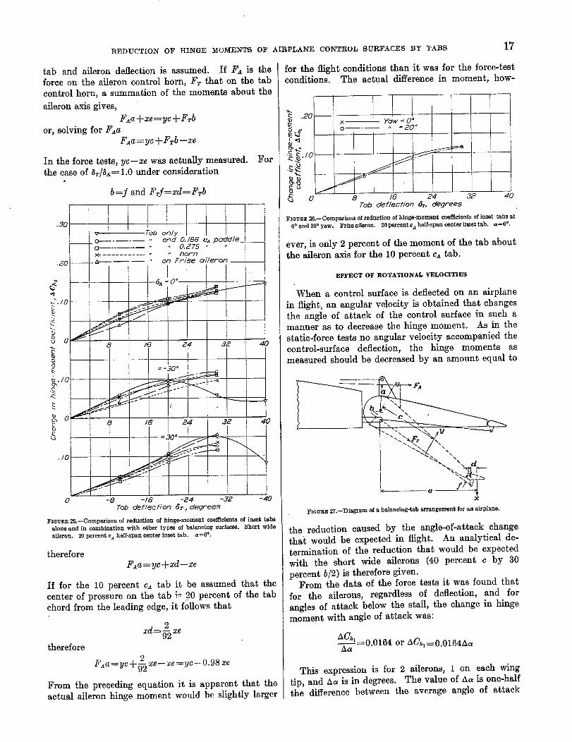
INSET TABS IN COMBINATION WITH OTHER TYPES OF BALANCE
A comparison of the actnal reduction in hingemoment for '_ tab on the aileron alone and on the ail-
eron with the auxiliary types of balance is shown in
figure 25. The curves are typical for 0° angle of
14 REPORT NATIONAL ADVISORY COMMITTEE FOR AERONAUTICS
.4
.2
02
k)
-.2
-.6
Ft :
-4
I
0 4
"x \
, !I IIIII I II I I I I.J_'\ I", I
l \1 I I I I I I/1', I I IN" ',t I ,-_
' -20 ° I
-/0 o
8 -/2 -8 - 4 0 4 8 /2
Elevator defle¢?/on 6z, degrees
(a) Inset tab 5 percent of maximum elevator chord. (b) Inset tab 10 percent of maximum elevator chord.
.4
.2
--.6
(j
_. ,,a'_=0° -I
-_.+o.___. (, /
" _]o2
-/o" _ _ 3o°
:8
f
/J
\
x\
/
i
f/
0 o
f //I_ / /
/ ' i/ \ ,,
II I
xI I i
..---" -/o-_jo+j-eo-/ 4
/
"6r-_ °
--20 -16 -12 -8 -4 • 0 4 . 8 /2 IG
Elevator deflecl/on 6_, deqrees
(c)Insettab 20percentofmaximum elevatorchord.
FI6UaE 22.--Variationof normal-force coefficients with elevator deflection for complete servo operation. Elevator 40 percent of area of horizontal tail. Reflection planein place.

REDUCTIONOFHINGEMOMENTS OF AIRPLANE CONTROL SURFACES BY TABS 15
attack; for the other angles of attack the change isabout the same. It is evident from these resultsthat the reduction in hinge moment due to the tab is
approximately independent of the auxiliary balanceor, in other words, if the lfinge moment is -known for acontrol surface with either a paddle, horn, or Frisebalance, the data reported herein may be used to cal-culate directly the further reduction in hinge momentthat may be expected by the addition of a tab.
Previous tests (reference 13) have shown that thehorn type of balance is ineffective at large angles ofattack and tends to overbalance when yawed. The
subject tests on the aileron with horn balance did notinclude the yawed condition but substantiated theconclusion that the horn balance is ineffective at large
angles of attack. (See table VII.)The tests with the Frise aileron yawed showed that
the reduction ofhinge moment due to a tab was thesame either yawed or unyawed (fig. 26). In thisfigure the change in hinge-moment coefficient causedby the deflection of the tab is plotted against tabangle. Since the change in hinge-moment coefficienton this type of aileron caused by a deflection of thetab is unaffected by yaw, it is reasonable to assumethat any other type of similarly balanced aileron andtab combination would be unaffected by yaw. Ifan aileron-tab combination is therefore not over-
balanced at zero yaw it will not be overbalanced bythe tab when yawed with the controls undeflected.It should be remembered, however, that all aileronstend to be overbalanced when the wing is sideslippedbecause of the unsymmetrical wing span load distri-bution under these conditions. This overbalance was
observed in the subject tests on the Frise aileron whenyawed and the amount of overbalance was consider-able at the high angles of attack. (See table VII.)When a balancing tab is attached to an aileron in aconventional manner so as to start moving at the sametime as the aileron and in the opposite direction, the
degree of overbalance when yawed will be greaterthan for the aileron without tab if the ailerons areallowed to deflect a small amount. It would be desir-
able to design the linkage of a balancing tab so thatthe aileron and tab would move together over the first4 ° or 5 ° deflection and then differentially to reducethe hinge moment. This arrangement would also bedesirable because of the fact that most aerodynamic
balancing devices tend to give overbalance at lowangles of c_ontrol-surface deflection.
FACTORS AFFECTING APPLICATION OF STATIC-FORCE
TEST RESULTS TO AIRPLANES IN FLIGHT
METHOD OF MEASURING THE HINGE MOMENTS
In the wind-tunnel l'orce tests where the tab was
part of the control surface, the measured hingemoment was the combined moment of the control
surface and the tab. On an actual airplane, how-ever, the arrangement would be more lilce that shown
]0
6_ O-- 6r = 0
a----- _ O_/eR= _..... . . =/
t
,30 °
I
..<o"
"" "_'_ :-_--_-_ 0
(a) 1-I.0. -.8 -.6 -.4 "-.2 0
Norrnol-fol-ce coeffl'c/en_, C_,
(a) Reflection plane in place.
l I /0
O_ dr 0
o....... , ,, = /I
(b)
-/.0
e
1
\,_a
_ !/0°
"- -o- .... cy-
8_
J
.(3S_.
cO
9L
4_
t.
z3
8_
JC
. C)
6c.Q)
Ltj
q)b
t.
2 _
0
=2 =6 -.4 -2 0Normal-force coeffl'cient, C_
(b) Reflection plane removed.
FIGURE23.--Effect of tab-rudder deflection ratios on the control-force criterion.Rudder 60 percent of area of vertical tail. Inset tab 20 percent of maximum
rudder chord, rF=0 °.
in figure 27. The following' discussion applies toany control surface, but an aileron will be treated forsimplicity. In the sketch the ratio of 1:1 between
14029:1--35-----3
16 REPORT NATIONAL ADVISORY COMMITTEE FOR AERONAUTICS
.4
.2
oQ_
Q_
i
-.4
-.6
-/g -/2 -8 -4 0 4 8 /2
Rudder def/ecHon 6_, degrees
(a) Reflectionplaneinplace.
16 20 24
.4
(b)I
-IG -8 -4 0 4 8 12 16 _0 24
Rudder def/ect/on 6_, degFee._
(b) Reflection plane removed.
FIGURE 24.--VariatJan of normal-force coemclent with rudder deflection for complete servo operation. Rudder 60 percent of area of vertical tail. Inset tab 20 percent ofmaximum rudder chard.
REDUCTIONOF HINGE MOMENTS OF AIRPLANE CONTROL SURFACES BY TABS17
tab and aileron deflection is assumed. If FA is the
force on the aileron control horn, Fr that on the tab
control horn, a summation of the moments about the
aileron axis gives,
FAa + xe=yc + Frb
or, solving for FanFaa=yc+Frb--xe
In the force tests, yc--xe was actually measured. Forthe case of (_T/_a = 1.0 under consideration
b=f and Frf=xd----Frb
1 I
.30
'_, TaD only__ o- ond O. 188 ca podd/e_ __
........ 0.275 "
x ............. horn.20___#_------- " on Fr/se oileron_
I
--- 6.:0 °I
.C. IO '
ou 0 8 16 24 32 4
' L= -30 °
_" _--×
_o 24 32 l 4
./o "_" '"_ _ \
0 -8 -IG -24 -32 -40Tob deflecfion 6r , degrees
FIGURE 2&--Comparison of reduction of hinge-moment coefficients of inset tabsalone and in combination with other types of balancing surfaces. Short wide
aileron, 20 percent e_ half-span center inset tab. a=0%
therefore
F,a=yc+xd--ze
If for the 10 percent ca tab it be assumed that the
center of pressure on the tab i_ 20 percent of the tabchord from the leading edge, it follows that
xd= 2 xe
therefore
2_FAn= yc 4- ,_ xe-- xe = yc -- 0.98 xe
From the preceding equation it is apparent that the
actual aileron hinge moment would be slightly larger
for the flight conditions than it was for the force-testconditions. The actual difference in moment, how-
.20
:_ _./o
"_.
oJ
16 24 32 40
Tob deflecf/on 6r, degrees
FZeURE 26.--Comparison of reduction of hinge-moment coefficients of inset tabs at0° and 20° yaw. Frise aileron. 2Npercent cAhalf-span center inset tab. a=0%
ever, is only 2 percent of the moment of the tab aboutthe aileron axis for the 10 percent ca tab.
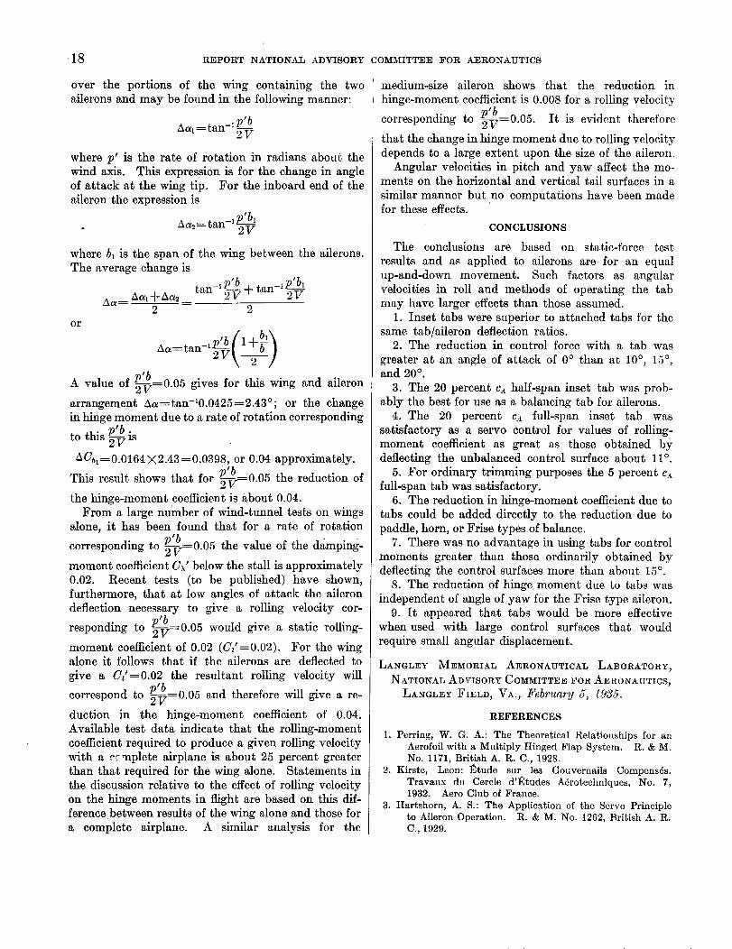
EFFECT OF ROTATIONAL VELOCITIES
When a control surface is deflected on an airplane
in flight, an angular velocity is obtained that changes
the angle of attack of the control surface in such amanner as to decrease the hinge moment. As in the
static-force tests no angular velocity accompanied thecontrol-surface deflection, the hinge moments as
measured should be decreased by an amount equal to
\ I
FIOURV-27.--Diagram of a balancing-tab arrangement for an airplane.
the reduction caused by the angle-of-attack changethai would be expected in flight. An analytical de-
termination of the reduction that would be expected
with the short wide ailerons (40 percent c by 30
percent b/2) is therefore given.From the data of the force tests it was found that
for the ailerons, regardless of deflection, and for
angles of attack below the stall, the change in hingemoment with angle of attack was:
AO_--0.0164 or AO_----0.0164AaAa
This expression is for 2 ailerons, 1 on each wing
tip, and ha is in degrees. The value of Aa is one-halfthe difference between the average angle of attack
18 REPORT NATIONAL ADVISORY COMMITTEE FOR AERONAUTICS
over the portions of the wing containing the two
ailerons and may be found in the following manner:
Aal_--tan-lP_
where p' is the rate of rotation in radians about thewind axis. This expression is for the change in angle
of attack at the wing tip. For the inboard end of the
aileron the expression is
_lp'blhas=tan
where bl is the span of the wing between the ailerons.
The average change is
__l;)'b t_._--Iptbl
Aa_Aal_kha___tan 2Vq-°_H 2V2 2
or
p'bA value of _-V----0.05 gives for this wing and aileron
arrangement A_----tan-10.0425--2.43°; or the changein hinge moment due to a rate of rotation corresponding
p'b •to this _-_ IS
hCh_=0.0164X2.43-_0.0398, or 0.04 approximately.p'b
This result shows that for _T,=0.05 the reduction of
the hinge-moment coefficient is about 0.04.From a large number of wind-tunnel tests on wings
alone, it has been found that for a rate of rotationp'b
corresponding to _-_=0.05 the value of the damping-
moment coefficient CA' below the stall is approximately
0.02. Recent tests (to be published) have shown,furthermore, that at low angles of attack the aileron
deflection necessary to give a rolling velocity cor-p'b
responding to _-_=0.05 would give a static rolling-
moment coefficient of 0.02 (C_'----0.02). For the wingalone it follows that if the ailerons are deflected to
give a C/-_0.02 the resultant rolling velocity willp'b
correspond to _-V=0.05 and therefore will give a re-
duction in the hinge-moment coefficient of 0.04.
Available test data indicate that the rolling-moment
coefficient required to produce a given rolling velocitywith a e_nplete airplane is about 25 percent greater
than that required for the wing alone. Statements in
the discussion relative to the effect of rolling velocity
on the hinge moments in flight are based on this dif-ference between results of the wing alone and those for
a complete airplane. A similar analysis for the
inedium-size aileron shows that the reduction in
hinge-moment coefficient is 0.008 for a rolling velocityp'b
corresponding to _----0.05. It is evident therefore
that the change in hinge moment due to rolling velocity
depends to a large extent upon the size of the aileron.
Angular velocities in pitch and yaw affect the mo-ments on the horizontal and vertical tail surfaces in a
similar manner but no computations have been madefor these effects.
CONCLUSIONS
The conclusions are based on static-force test
results and as applied to ailerons are for an equal
up-and-down movement. Such factors as angular
velocities in roll and methods of operating the tabmay have larger effects than those assumed.
1. Inset tabs were superior to attached tabs for thesame tab/aileron deflection ratios.
2. The reduction in control force with a tab was
greater at an angle of attack of 0 ° than at 10 °, 15 °,and 20 ° .
3. The 20 percent cAably the best for use as
4. The 20 percent
satisfactory as a servo
half-span inset tab was prob-a balancing tab for ailerons.
c_ full-span inset tab was
control for values of rolling-
moment coefficient as great as those obtained bydeflecting the unbalanced control surface about 11 °.
5. For ordinary trimming purposes the 5 percent c._
full-span tab was satisfactory.6. The reduction in hinge-moment coefficient due to
tabs could be added directly to the reduction due to
paddle, horn, or Frise types of balance.
7. There was no advantage in using tabs for control
moments greater than those ordinarily obtained bydeflecting the control surfaces more than about 15 ° .
8. The reduction of hinge nmment due to tabs was
independent of angle of yaw for the Frise type aileron.9. It appeared that tabs would be more effective
when used with large control surfaces that would
require small angular displacement.
LANGLEY MEMORIAL AERONAUTICAL LABORATORY,
NATIONAL ADVISORY COMMITTEE FOR AERONAUTICS,
LANGLEY FIELD, VA., February 5, 1935.
REFERENCES
1. Perring, W. G. A.: The Theoretical Relationships for an
Aerofoil with a Multiply Hinged Flap System. R. & M.
No. 1171, British A. R. C., 1928.
2. Kirste, Leon: l_tude sur les Gouvernails Compens_s.
Travaux du Cercle d']_tudes A5rotechniques, No. 7,1932. Aero Club of France.
3. Hartshorn, A. S.: The Application of the Servo Principle
to Aileron Operation. R. & M. No. 1262, British A. R.
C., 1929.
REDUCTION OF HINGE MOMENTS OF AIRPLANE CONTROL SURFACES BY TABS
4. Garner, H. M., and Lockyer, C. E. W.: The Aerodynamics
of a Simple Serve-Rudder System. R. & M. 1105,
British A. R. C., 1928.
5. Garner, H. M., and Wright, K. V.: On the Use of a Follow
Up Mechanism in Aerodynamic Serve Control Systems.
R. & M. No. 1187, British A. R. C., 1929.
6. Wright, K.V.: Wind Tunnel Tests of Various Serve Rudder
Systems. R. & M. No. 1186, British A. R° C., 1929.
7. Serby, J. E.: Full Scale Experi_ients with Serve Rudders.
R. & M. No. 1514, British A. R. C, 1933.
8. Reid, Elliott G.: Serve Control Flaps. Aero. Sci. Jour.,
vol. 1, no. 4, October 1934, pp. 155-167.
9. Hartshorn, A. S., and Bradfield, F. B.: Wind Tunnel
Tests on (1) Frise Aileron with Raised Nose. (2) Harts-
horn Ailerons with Twisted Nose. R. & M. No. 1587,
British A. R. C., 1934.
19
10. Harris, Thomas A.: The 7- by 10-Foot Wind Tunnel of the
National Advisory Committee for Aeronautics. T.R.
No. 412, N. A. C. A., 1931.
11. Heald, R. H.: Rolling, Yawing, and Hinge Moments
Produced by Rectangular Ailerons. T. N. No. 441,
N. A. C. A., 1933.
12. Soul6, Hartley A., and Wetmore, J. W.: The Effect of
Slots and Flaps on Lateral Control of a Low-Wing
Monoplane as Determined in Flight. T. N° No. 478,
N. A. C. A., 1933.
13. Irving, H. B., and Batson, A. S.: An Investigation of the
Aerodynamic Properties of Wing Ailerons. Part IV.
The Effect of Yaw on the Balance of Ailerons of the
"Horn" Type. R. & M. No. 728, British A. R. C., 1922.
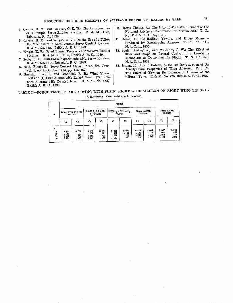
TABLE I.--FORCE TESTS, CLARK Y WING WITH PLAIN SHORT WIDE AILERON ON RIGHT WING TIP ONLY
[R. N.=609,000. Veloeity=8O m.p.h. Yaw=0 °]
Model
Frise ailerona balance
Wing with or with-out tabs
O. 361 O. 021
1.060 .092
1.260 .147
1.194 ] .265
0.1875 c4 by 0.445
b_ paddle
eL C_
0.395 [ 0.023
1.068 / .0981.260 t .157
1.128 [ .276
0.275 cA by 0.445 b A Horn aileron
paddle CD C_balance CDCL
o 3s1 0,o37 l 0.429 o.o_1.054 .102 [ 1.186 .114
1.254 .159 ] 1.360 .179
1.1261 .270 / 1.212 / .275
C_, C_
0307 Ii.040 : 148
1"2_ I .246]1.194
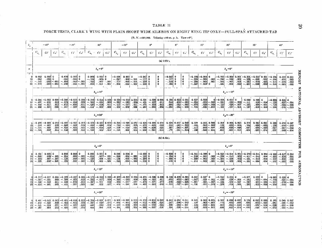
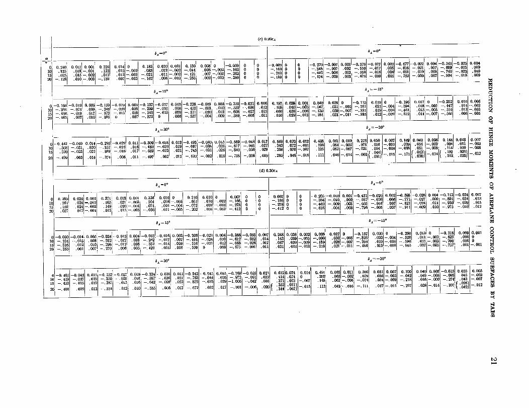
TABLE II
FORCE TESTS, CLARK Y WING WITH PLAIN SHORT WIDE AILERON ON RIGHT WING TIP ONLY--FULL-SPAN ATTACHED TAB
[R. N.=609,000. Velocily=80m. p.h. Yaw=0 °]
i
I
--40° --30° --20° --10° I O° O° 10° 20° 30°
(-'J'l Cz" C," Ch: CV C, J Ch I C/ C,,' Ch I Ct' CJ I C_q C_' CJ Ch I C/ C_' Csq C_' Cn' Ch I Cz' C," Ch I C/ CJ Ch,
40 °
el' Cn"
(a) 0.05c_
F
t_
_i 0:00_000321 oo,ol0.0020 oo09joo01po[-ooo,I 0002101-004710
-.0881 .0031 0 i -•104[ .002 0 -.097 .oo31-.OOll --•177[ 0
--. 083 • 002 --. 001 . 002[--. 001.-_::_ .002-.00,,-.180 -. t82 .001-.001-. 173.oo3-.001[-._9,0
.003d-.00,I .30_--. 2901 --. OOl --. 001 --. 284 .003 --. 001 --. 3380P
6A=0 ° 5A=0 °
--0. 047
o° -.177o°o =:._oo
-0.100-0.0040[-0.1001-0.00_1o.o041-0.204[-o.010[0 --• 229 --. 003 . 001 i --. 2021 --. 008 i • 0021 -• 3_1 -. o001
0 --. 208 --. 003 . 001 --. 346] --. 007_ . 002] --• 387[ --. 0101
--.397 --.0020 --.446 --.004 .002 --.487 --.006
0.001[--0.2261 O.Oll I 0.001
• 0021 --. 3661 -. 0111 • 003
• 003 -.411 -.010 .003.003
.002 --•510 --. 005
_0
_t =15 ° _=--15 °
01-02401-0023100o5i-02461-0022100051-02401-002;0•0o5I-0•_8J-0•022t00051-030110•0_1 0_210_41003710•029101-0005t0.02710I-0_110] --.407 --.020i .010] --•3781 --.016] .0O9] --.382 t --.0211 .0091 --.3821 --.020] .0091 --.436] --.022 "0351--'005] --.070 .0321--.005 [ --.081[ .029[--.0051 --.111]151 --. 444] --. 0171 . 012 --. 415l --. 016 .0111 --. 4201 --. 018l • 011 --. 413 i --. 0171 . 011 --. 472] --. 020 i .032 --. 007 i --" 024 .029 --. 008 --. 125[ .026 I-. 007] --. 157[
20 -.468j -.0011 .023 -.011 -._61.025 --.009 --. 103. 009 --. 441 --. 002 . 008 --. 454 --. 003 o211-o!oI-lO7I• 008 --.430 --.002 .008 --.494 --.0031
5A =30° _,t =--30°
,! o 4,8-oo30t-:514l-:o32[--.551 --. 025
--.516 •002
00,31-04071-0037100,31-03761-0037t0101-. 5081-. 0301.0,0 -. 402,-. 030
021 --.529[ --.0241.022 -. 538 -. 0231.014. -- 510 003 014 --.508 .002
O. 013[--0. 393[--0. 036[
• 019[ --, 5221 --. 030 I
• 021 --. 558 --. 024[
.014 --. 516 .003
0.006[ O. 1011
.011[ ._42
•012 __: 034
.009
00121-04_L-0_0i0014103041005710•00010320i.0101 --.576] --.035[ .0221 .216] .065]--.0O2J .165[
.015 .187 .062--.0071 .117
• 021 -.599l --.029[ .o28
.106• 041 --• 014[.014 --,5501 --.001 .175
00_1ooo8o.264[00501o_,l 02181• 063l--. 002 .120] .059[--. 003 I
.059 .058 --.0O8• 060 --. 00_ .0511
• 040 --. 015 [
• 035 --. 015 _
oo_[o [-oo2oloo_[o• o28]-, oo41 -. 1251 .027[-. o04• 026 -. oo71 -. 1761
• 019 --. 010 --. 226 ."018024--.--"010006
00_00_ o_ 0.050[0.007:0oo-: oo81 .057-. 0os.0o5-.o14 !_,_ .o6o1-.oo2
• 040 --. 014
O
o
.<
0
0
N
r/1
2(
(b) 0.10c_
5a =0 ° _ =0 °
l! o121t-. oo310.000[00.0891o.oo6[0t0.083[0.0071010.0481o.o04o-0.029
• 009 I-. 001 --. 0341 .006 I-. 001 i --• 034.007 --. OOl --. 128 .005 --. 001 --. 122 • 0071-' O01i --" 050[ .005[--. 001 i -. 1351 0
• 006 --. 0011 --. 134 .005 --. 0O2[ --. 206 i
.006 --. 001 • 005 --. 001 --. 219 .005 --. 002 .004 --. 002 --• 318 0--. 229 --. 242
0--0. 21-_---0.017
10 --.387 --.021
--0. 029[--. 1351 0
::_o_°o
-o.141-o.oo6o[-o._[-o.o,11o.oo1[-o._0[-o.o141O0 --.240 --•005 .0O1[ --.3381 --.0101 •0021 --•411[ --.0141
O0 --.300 --.005 .0Ol --.384[ --.0081 .0021 --.451] --.012[
--.414 --.002 .001 --.494 --.003 .003 --.551 --.004
_ =15 ° _=--15 °
0. 0051 --0. 229[--0. 0271 0. 005]--0.173 t --0. 020 t 0. 005[--0. 206 --0. 0231 0. oo51-o274[--0, 0281 0. 0off
.009 --.398 --.023 .010 --.282 --.017 .008] --.346[ --.020] .009 --.438 --.025] .011
.011 --.429[ --.0191 ,011 --.2971 --.011[ .008 --.383 --.017 .011 --.474 --.0211 .012.010
.008 --.489 --.002• 000 --.4631 --.001 .009 --. 335 .002 .007 --.418 --.0Ol
0.129 t 0.0331 0.0O1[ O. 031j 0.027[0 ]-0.0421 0.024[0 I-0.077].065] .035]-•005l --.047
028] .033--.0O8 --.091 .0291--.005[ --.136[ .026[--.0041 --. 191[
• 027 -. 007[ --. 182 .024 --. oo71--•247
--_015 .027--.011 --.126 .021 --.010 --.230 .018 --. 009 --.295
_=30 ° 6a =--30 °
0.011[--0.368[--0.0381 0.013[--0.472[--0.043[ 0.0,t6
• 0171 --.505 --.031 .020[ --.6121 --.0381 .024
.019 --. 552 --. 026 022 --. 640] --.030[ . 025.016
014 --. 566 --.005.013 --. 494 .003
0;]-0. 401 --0. 04310 013 --0 404[--0. 0401 0. 013[--0 268[--0. 033[
IOL -- 433; -- 025 .0,9] -.4831 -.032l .o,s} -.3971 -.028 l151 -. 521 -- 024 .0201 --. 4431 --.020[
2ol -.4871 .004[ "°21_ -. 5211 -. 025[ .014] --.408] oo6I.o15 t -.405 i .oo6!
0.444[ 0.064 t 0.0111 0.3421 0.055[ 0.009[ 0.258[ 0.000[ 0,007t 0.178[
:22_ .068-.002' .158 i .0631-•0031 .116[ .0591-.003] .086 I.064 --. 0071 .125 . O60 --. 0081 .042 .056 --. 0081 --. 006
• 194 .058 --. 014 i . 119 .053 --. 015 --. 030.047 --. 014.026
o.0o2l-o._[-o. 017iO.002• 0O41 -.4931 -.016l .004
.0O4 --.537 --.016 .005
.004 --.627 --.005 .005
00=[0[-00o3[0.o20[0.023l-.0041 -.2291 .0211-.0O4.021 --. 006[ --. 291[
• 015 --. 008 --. 350 ."018019_--" 008006
o.o431ooo6[o•1_1o.o_81o007• 0551-. 0031 .0611 .0561-. 002
-- 029 .053 --. 008
• 053 --. 008 __ 075• 046 --. 014 . 035 --. 013
I
a
:i
(c) 0.20ca
_A=O°
0.017t 0.0011 0.226 t 0.014 0 0.1831 0.010 0•001 0.1301 0.00810 --0.009.083
.018'--• 001 .1231 .015 t-. 002 --. 021 .012 --. 002] --. 0141 .008 --. 002 --. 100 0.015 --. 0021 .012 .013 --. 002 .011 --. 002 / --. 121 .007 --. 002 --. 263
• 002 --.003 --.389 0--. 253.O06 --.003--. 139 .007 --. 003 --. 102• 010[--. 003
_a =15°
-0.1661-001ol0005-0.150-0 0190 oo5-0.137--0.017 0.005[--0.228--0.0191 0.005--0.355--0._01 O.O0_l21_ --.366 --.02I 009 -- 348 -- 020 000 -- 299 -- 016 008 -- 452 -- 023 . 10 --.55 --. .15 --.436 --.019 i 012 -- 373 -- 015 010 -- 343 -- 013 000 -- 511 -- 020 .012 --.608 --.027 .015
2c-465 0071010I_38510 i007/-872101"°°°/-5371-°°4/°°9t-53°1-o05/°111_ia =30° /
,-0442-0o*oo014-0295-00290011-0_09-00340012[-0493-0o*o0015-05591-0o.80.0171_) -.503 -.031 020 - 357 - 024 016 - 489 -- 029 019 - 697 - 038 .024 -.817 -.045 .027[
] -.520 -.023 .021 -.389 -.016 .017 -.539 -.023 .021] -.745 -.031 .026 -.840 -.036 .029[
2) --.499 .003 .014 -.3741 .006 .011 --.497] .0021.013 --.6391 -.002 t .016 t --.718] --.008[ .0191
oo,oli o 7oLo TL--. 160] 0 --. 348 --. 007
--. 263 0 --. 440 --. 006L-5761-0081--. 189 0
0.1971 0. 038 0. 001 0. 040]
.1081 . O*O]--. 00"51 --. 067t038--008 --130
O6Oolo:o291-:o13-:184t
_a =0°
0.O01--0.876--0.017 0.0021--0.477--0.0221 0.004--0.541--0.025 0.O04.002 --.510 --.017 .005 --.616 --.021 .007 --.699 --.025 .009.003 --.558 --.016 .006 --.66l --.019 .008 --.740 --.023 .010
.007 --.804 --.010003i -8751=0001o05-732-o09 000_A = --15°
0.029 0 --0.115 0.010 0 --0•196 0.017 0 --0.202 0.016 0.006.031 --. 005 --. 261 .021 --. 004 --. 394 .018 --. 002 --. 447 .014 I-. 002•029 --.007 --.331 .019 --.006 --.4611 .0151--.005 --.516 •013 --.003
.006 --.O05•0111--.O07 --.566.021 --. 011 --. 385 • 012 --. 009 --. 512
0. 5691 0. 0701 0. 012 I
.343_ .072 --.O011
I .070 --. 007.'285308 . 046 --. 015
_A =--30°
0.O.30.O07
• 051 --. 003.05O --.OO8
:_329} -.013
043810o011001010.2730o5o0o07014900420_ 01..198] .0O.1--.O02] .075 .056 --.O03 .029 .054 --.003 .O04
125 002-0_-•031o_ -008-171{:_}-0,4( :1_--'0611{ " 00_41}i--"0151--. 038] .051 --.O081 .114,.111 .040 --. 014
O
Z
O
(d) 0.30CA z
0.389i 0.024 0.002 0 0.0181 0.0011
.261' .024--.O02i ]i!ii 021 --.003• 1501 .024 --. 003 .0201 -- 004 I
.0271 ,017!--. 004[ .0151 .015'L--. O051
_A =0°
i T0•336 0.016 0 0.210 0.016 0 0.007•204 . 018 --.003 . 051 . 01C --. 002! --. 166• 074 .016 --. 004 --. 072 .00_ --. 003 --. 278
--. 056 . 011 --. 005 --. 202 . 00{ i--. 003 --. 412I
]A = 15°
, i I _ I-0030-00140•o05-003_-00150o04-006_-00100o03-0._8-00_300.-086_-_4 -015 008-202 -017 008 -28_ -017 007-444 -024 010-01_--.316 --.012 .0101 --.298 --.0121 .008 --.35_ --.014 .009 --.516 --.021 .012 --.66_
--.353 .001 .007, --.270!1 .006 .005 --.42( .O01 .0061 --.559 0 .008 --.67_
_a=30°
--0. 401 --O.o*ll O. 0151--0. 152 --0. 027 0. 010 --0.334 --0.03_ 0. 011 --0. 542 --0. 045 0. 015 --0. 769--.419 --.027 .01_ --.35G --.025 .016 --.537 --.03( .021 --.7_ --.044 .026 --.972--.410 --.0H .019 --.385 --.015 .016 --.642 --.02{ .023 --.825 --.035 .02(J --1.006
--.400 .0_ .013 --.334 .012 •010 --.535 .006 .013 --.67I .002 .017 --.801
o o0
o o0
-0.033 0.007--.032 .014--.028 .017--.O01 .011
--0.0550.021 !
--.051] .032
--.042 .035
--.O06 .029[
--. 278--. 412
O. 248.143.087• 031
O. 612.414.371
. 35_.344
000 00 0
0.038 0.O02.039--.O05.039--.O00.033--.013
0.07410.014 I
.074 0 I.073 ] --. 007.051. 7//o15
}A =0°
--0.0100.001--0.431 I 0.004--0.713--0. 2051 --0. 020 O. 002 --0. 59_ i--O. 028 --0. 034 0. 007
--.384 _ --.010 .002 --.597 --.020 .006 --.77] --.027 .000 --.891 --.034 •013--•469 --.00_ .003 --.665 --.016 .007 --.82l --.024 .011 --.930 --.029 .015
--.625 .0041 .003 --.796 --.005 .007 --.911 --.0(N .010 --•975 --.010 .012
_a =--15°
I0.026 0.027 0 --0.157 0.020 0 --0.290 0.013! --0.318 I
OO4 520 .011 0O3 --. 023--. 090 .030 --. 005 --. 3_ .020 --.--. O.--. 700[
.028 --.007 .019 --.00_ --.59_ .011 --.O03--. 159 .021 --. 011 --" 008 .015 --. 008 --. 643 .007 --. 005 --. 7571--. 218 --. 45{
!
5a = --30°
O. OO90.001.0060.0050.001 --. O01
0.4911 0.065 0.011 0.306 0.051i0.007 0.10C 0.040 0•005--0.015 0.035 0. O0_.202 .065--.002 .079 .05{ --.003 --.O*_ .049--.003 --.095 045 --.00",
..148113 .063 --. 008 --. 074 .054 --. 000 --. 218 .046 --. O0(J --. 274 { .02._"o43 I_-OO_ol,
! .043 --.016 --.111 .047 --.015 --.29_ •038 --.014 --.397 .o*2J '
O
>.
Z
CaO
O
0_
bO

TABLE III
FORCE TESTS, CLARK Y WING WITH PLAIN SHORT WIDE AILERON ON RIGHT WING TIP ONLY--0.20cx HALF-SPAN ATTACHED TAB
[R• N.=609,000. Velocity=80 m• p.h. Yaw=0 °]
_T[ --40°C h Cd C_'
--30 °
On'
-20 °
Ch I C/ C. I Chl
0 o O* 10 ° 20 °
CJ Ch, C/ C.' Ch, C/ CJ Ch, C/ [ Cn' Ch,
30* 40 °
Ch, C_' C_' C,' C^, C/ Cn'
(a) Outboard
5a=00 6A =00
0.11110.008[ 0.00110.09910008000010.0074 0.005] 0.000 t 0.02410.00210.000[--0.034[ 0.034[ --0.100--0.0040.000l--0.1991--0.007 ] 0.001[--0•2631--0.011] 0.001l--0.3001--0.013]
_:00_ •010,0 [ •0301:0101-:0011 008,-0011-0501 0o6]-.001-1_1 0 0 -•138.0 0 -214 -oo3 •0011-3211-007, •00_,-380, -011, oo_l-4421-•013,-151 ,:20_ 0031-.4301-0101
• 009 --.001 --. 022 .009 --.002 --: 064 .007 --.002 --. 140 .002 --.0011 --.208[ 0 0 0 0 --. 282 --. 004 .001 --. 374] --. 007• 003 -- 522 --.011 .004 --.487 --.012]
--. 230 .001 --. 001 --. 2960 0 0 0 --. 369 --. 002 • 001 --.455 --.006• 007 --. 003 .005 --. 001--.100 .008 --.002 --.117 " {--.007' .004 --.561 .007
'_a = 15° _A = --15°
o
0
101,5
2°
0-01001-001010.005-0.110-00,8t0_1-0.153-001000,1-0.1641-00_to.o_l-o_31-0024100_,011110033f0_110.05710.030[0001]-00_1oo_lo I-0.0711oo_lo 1-0087100_10.001.048
10 --.276 --.018 .009[ --.294[ --.0181 .009 --.3571 -.o19[ .0091 -.3751 -.019[ .010[ -.480l -.023l .0111 .010 •035[-.005} -.0141 .0321-.005] -.112[ .030l-.005[ -.170[ .023[-.0041 -.216} .023l-.00315 -•377 -.019[ .011 -.358 -.019 .011 -.408 -.016 .010 -.4311 -.016[ .012 -.531[ -.024 •013 .032 -.0081 -.050 .029 -.007 -.1621 •027 -.007 -.234[
.010 --. 542 --. 007 --. 027 .019 --. 004--. 097 .023 --. 010 --. 210 .016 .--.010 --. 279.024 --. 012 ,020 --. OO6l -. 233l.010 --. 450 --. 003 .008 --. 463 --. 0082(] --.398 --.008 .009 --.403 --.004 .010 .014 --.008 --.329 .012 .007
,_ =30 ° ,_A= --30 °
0_0.3_7_0.0_0o.013_0.__0.o33o.012__0.3161-0.03:1o.0121-0.3_1-0.,11o.0141-0.4_1-0.,31o.015,o.4621o.0501o.0111o._941o.0571o.
• 018 .231 .056[--.002] .180l .063[--.0021510 --.-- 4734571 --.-- 031026 .020010 ----" 4.303021----"02210271 .' 01010171014:i--._.--"48814531470[--'--'--.007]°27l°3I ."0210181-._. 5705401-.-"030[°38l.*0230211--'--. 034616[ --._. 0391032] ."025023 .. 199176 "_ --" 006[ .139 .061 --. 007
20_440{-°0_}015-413-001•039 --. 014.017 --. 576 --.010 .122•015 --.531 --.007--. .042 --. 014
0.281{0052l00O8{0198[ oo47lo.oo6]0164] 0.047[0.007.1411 .O8Ol-.OO21 .o8,
".035O65 .058 --.007 .010 ."055l-.002[053--. 0071 .'001[025 ."055[--.002053--. 006• 037 --. 015 --.029 • 031 --•014 --. 047 • 031 --. 013
,oO. 002 0
• 005.000
.006
0
©
©
(b) Center
I($a=0° 5A=0°
01_10:_ 00110080100o80001i00_3ooo710I o•_ol0.003101-002; -00_1 -01_0-00_0001-0190_00070 -0256_00110•0021-0•_61-001210_2-0, 0° -010t 011-001-022 0o81-001_-0741003_0i-l.t ° o ::110_0 °0 -310-00_003--.O89 .0070 --.1001 01010 I --.102 .008--.001[ --.151 .0040 -1_ I0 0 0 0 --•229 --.005 .0O2 --'376{--'0005}"003-'316--.003 .002 --.423--'3761 --.004_.002 ,005"004] -'4791-'431[-.012-'0131 .o60"0°3
-202 .O05 --.210! .003 i 0 --.223 ,0050 --.268 .002 .001 --.2500 0 --.250 [ 0 0 --.416 --,004 .003 --.483 ----_001 .003 --.529 --.005 .005 --.560 --.005 •006
_ia =15° 5a=--15°
' I-002,0.005-0215oo240.0051-0.198-0017100051-0254-00230.0061-0.2711-0.027100_[003_10034I0.001t00371003010.0011-0.018}00_10 10_6]0.o23]01-00_410•02310.001--.022 l .0101 --.3731 --.021 t .009] --.3531 --.0161 .009 i --.405 --.022 .010 --.456 --.026 .0111 .043] .0351--.005 ] --.0301 .031]--.0041 --.099] .027]--.0051 --.168] .023]--.004] --.1981 .022]--.003
--.020 •019 --.409 --•015 .011 --.396 --.010] .onl-.455 -.0191 .013 -.512 t -.022[ / •013 .033-.0071-.076 .029 -.0061 -.143 .032-.006 t -•212 .021-•005 -.252[
.010 --.539 --.003 .0_5 / • 025 --. 010--. 013 --. 1150091-4761-0041 022-060-_6 023-000-257•00_-416-001 •021]-004.016 --. 007 --. 307-00_i 011!-3031-0011 .015 I-. 006
_ =30 ° ,_ = --30 _
0i-0.410l-0.03310.0_4[-0.3331-0.0310.013-0.382-0.0330.013]-0.439[-0.038]0014t-05311-00d00,6_o=f 0o611oo,ot0.361I0055loo0910_3100_51000_[0_0]0.0401oo0810.23410.049[0.007
lOJ --.4501 --.030 .0101 -.425 -.025] .0181 -.504 -.033[ •0191 --.593[ --.036[ .0221 --.O61} --.040] .0241 .232] .O651-.0011 .162[ .O611-.0021 :_42_ .059l-.003 [ •1211 .055l-.0011 .077[ .055J--.002
• 023 --.636] --.0_ I 025[-716[-•o33 t .o18 .113 .060 -.o061 .057l-.007 [ .001] .053 -.006 I
15 - 4811-.021[ .0211-. 4_s -.017 .020[-. 551-.026! .028 . 193 . 064 I-.0061 --. 032 .052 --• 007
20 --. 494 •002 .016 --.440 .004 .015[, --.4961 .O01[ .015 --.5640 .0161 --.615[ --.. 003] .181 {'.00"512} --.013 .102 .051 --. 013 .028 03aI-. 010 I_ --.025! • 033 --. 012 --. 059 .054 --. 012
©
>
0Zm
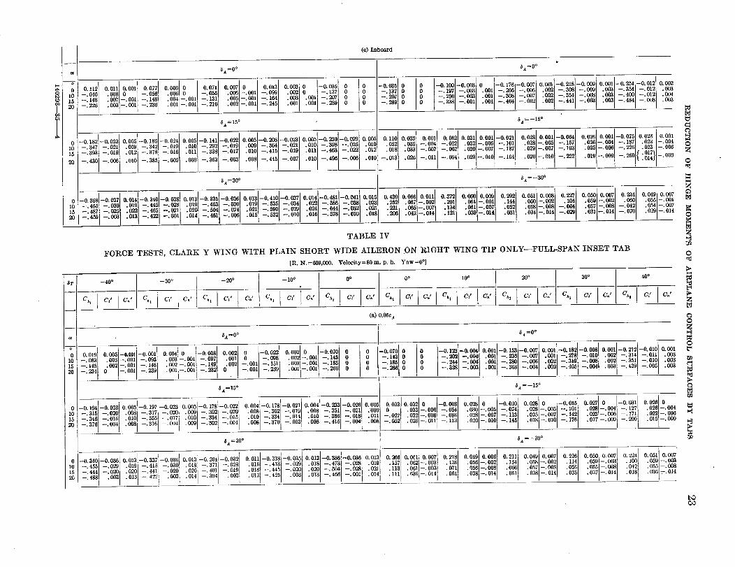
(c) Inboard
6,4=0 ° _a =0°
O. 002o o •003
• 004
0° 0° .0o30 0.,120.01110.09110.0771o.0o6o 0.07110.oo7o 0.0131o.oo3[o-0.0351
10 -.0401 •0080 --.0561 .006[ 0 [ --•056[ •0061--.0011 --.0991 .00210 [ --•1371 O0_ -- 164 .003 .091 --.207
15 --.148 .007 --.091 •004 --.001 --.131 .005 --.001 --_245] .001 .091 --.289 0
20 2261 .003 --.001 --:14_ .001 --.001
•002 --•001--. 210
0 --0.182 --0• 023 O, 005 --0. 185 --0. 024--.347 --.021 .009 --.342 --.019
15 --.303 --.010 .012 --.378 --.016
--.430 --.006 .010 --.335 --.005
i0
20
0I01520
-0.035 I-. 1371 O0
--. 207
--•289 0
-0.368--0.037
--.455 --.030--.487 --.025
--.459 --.003
v
-0.1001-o.o03[0 -0.176-0.007o.o01-0.218-o.o090.001-0._4-0.012-.107-.oo3.001-.266-.oo6.0021-.3o8-.oo9.0931-.3_4-.012-.25o-.0031.o01-.308-.oo7.oo2-.364-.o03.003-.409-.012
.002 --.441 --.003 .003 --.484 --.008.091 --.404 --.002--.338 --.001
5a=15o 5A=--15°
0.005-0•141-0.0220.005-0•208-0.0280•005-0•280-0•0260.0050.11010.03310•00110.05210031L0•0011-002110•02210001-0_0.0260.001-0.0750•0230.001.010 --.262 --.019 .0901 --.364 --.0211 .010 -- 398 --.025 .010 •0521 •0351 --_00_ --.0221 .0321--.005[ --•1011 .028--.005 --•157 .026--.004 --.187 .023 --.004
• 011 --.338 --.017 .010 --•415 --.019 .Olf --.403 --.022 .012 .018 .033 --.0521 .030--.0071 --.137[ .026 --.007 --.193 025 --.005 --.226 •023 --.006.010 --•4961 --.005 --.013 .026 --.011 .023--.010 --.104 .020--.010 --.222 .010--.009 --•260{ :_}--.009• 099 --.363 --.003 .008 --•445 --.007 .010 --.094
_A=30o _ =-30°
O. 014 --0. 481 --0. 041 O. 015.022 --.586 --.038 .023.024 --.044 --.032 .02_•016 --. 578 --. OlOI .018
I
0 014--0 340--0.038 0.013--0.335--0.036
.010 --.445 --.022 .010 --.463 --.030022 --.465 --.021 .020 --.504 --.024
:013 --•422 --.091 .014 --.461[ --.005 II I
O. 013--0.410--0.037.010 --.535 --.034• 021 --.590 --.026[.015 --.5321 --.010
I
0•0010 00.0110•3721o•-i t 0051 0.00310 0.0500.0070 410.0401000 252,037,-002,201,_,-091, _0/-09211041050-002050t 055001.2211 .0651--.0071 _2M I .0611--.0971 :0521 .0581-.0981 .057-.098-042 .ora-.oo7.206[ .o42/-.o14 [ .o391-o141 .0311 .o341-.o141 -:o°°_ .o31-.o14 -:070 .026-.o14
TABLE IV
FORCE TESTS, CLARK Y WING WITH PLAIN SHORT WIDE AILERON .ON RIGHT WING TIP ONLYPFULL-SPAN INSET TAB[R. N.=609,009. Velocity=80 m. p. h• Yaw=0 °]
C
©
©
O
0
6r I
J
a
i-z-I
152O
010152O
Ch I
-40 °
C_s Cn'
--30 °
Ch I Ct t Cn'
--20°
Ch _ C_' CJi
- 10°
Ch CI'
0 o 0o
'2.' Ch_ C/ 6'.' C h C/ C.' Ch
10o 20°
C* t C/ CJ C,h C/ C,,'
(a) 0.05c A
[ 54 =0 °6a=O o
I0.019 0.005--0.001 -0.001! _ k 0.002 0 --0.022 IO. 004 0 --0.008 O. 002 0 --0 070
--.083 .003--.001 --.095 .003 --•001 --.097 .001 0 I --.098 .002--.091 --.143
•002--.091 --.149 .002 --.091 --.151 .003--.001 --.185 0
--.234--"145 0-092 --.--'091091--.__.239148 "O01i--'O011 --.232 0 --.091 --.289 .001 --.001 --. 266 0
--0. 070--. 143--. 185--. 266
0 0 --0.1230 0 --. 20,_0 0 --.2440 0 --. 32_
30 ° 40 °
C/ C.' Ch, C:' CJ
I--0.004 0.091 --0.153 --0.09_ 0.091 --0.182 --0.098 0.001 --0.212--0•01( 0.091--.004 .091 --.286 --.09_ .001 --.278 --.010 .092 --.314 --.011 .00_--.004 .001 --.280 --.09( .092 --.31_ --.098 .002 --.351 --.01( .09_--.093 .001 --.368 --.004; .002 --.40_ --.004 .093 --.439 --.005! .00_
_,t=lS° 5a =--15 °
' _ --00311 0.026 0
_0104-00_0005!_010_!-0023,0.005-0.178-0.02210.094-0.178-0.0210•0041-0283-002_000_o.028003_0 -o•03800220 -00100.02810-0•01_oo27o _.1--1127 .026 --.00_--.315 --.02(] .008 --.317 --.0261 .009 --.302 --.0201 •008 --.302 --,019 .008 --.351 --.021 .'OOC_ .033 --.0061 --.054 .030--.095 --•074 .022--.095 --.101 .022--_ .022 --. 09(--. 008 --. 08(] .028 -. 007 --. 113 .025 --. 007 --. 14_ .023
--.17f --.209 .015 --.09!--. 145• 020 --. 010
.010 --.386, .011 --.027 .03__.011 --.I13 .017--.015 .010 --.334 --.014] "0081 --'4151 --.018.0101--.355--.017 .010--.334 _.00,t .008--.370 00_ --.094 .0081--.052 .02_ .018 --.010 --.00_--.--'376346--.--'0040111"0081 --.316 --. 004 .009 --.302 --.
_a =30° _a =--30°
10-.0340-0•0360.013-0•337-00360013i-0204_-0•0320.011-0313-0.03500_3-0.336-0.0360.013o=i0•0(]1i0.00710•21810.0400.00010.21110.0400.007o_ol0.0500.0070•_I0.0510•007--.455 --.026 .019 --.415 --.030 .018 --. 371 --.0281 .016 --.413 --. 026 .018 --.473 --,028 .019 .1571 . 062 --. 003 .136[ .056 --.002 .134] .0581--.0021 .1141 .059 --.003 .100 l .059 --.003026 --. 401 --. 010 .018 --. 445 --. 020 .020 --. 504 --. 028 .02] .113 .061 --. 0031 .071 .056 --. 0081 066 .057 --. 0081 .056 .055 --. 0081 .0_2 .0551--.098
.036 I-r-. 014• 018• 037 --. Ol 415/ --'444 --.020 .020 --.441 --.020 • 038 --.O]4 • 035• 038 --. 014• 064.111.013-.46_-.001 014 .036t- 0141 :051013 -42_ .003-4_ .003 .013-422 .003 •01, -394 003I
Z
C_0
0
c
tO
b_C,O
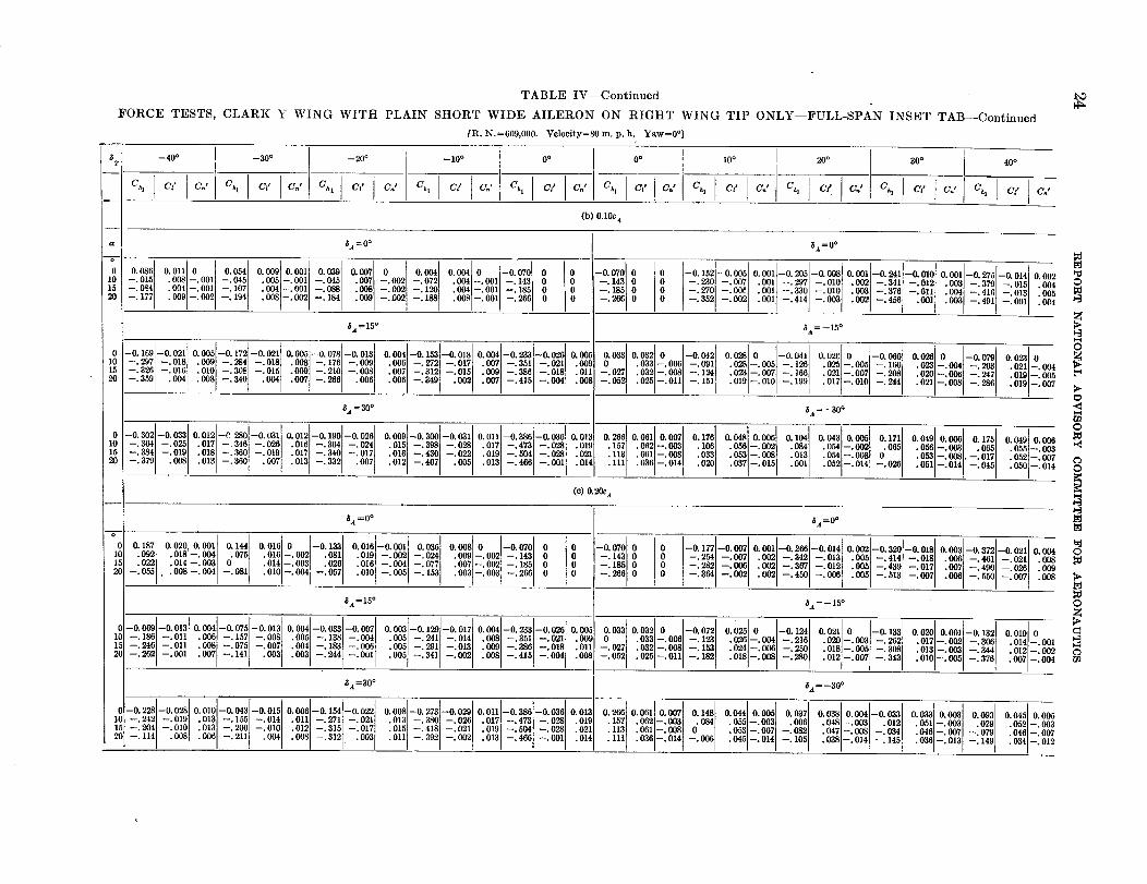
TABLE IV--Continued
FORCE TESTS, CLARK Y WING WITH PLAIN SHORT WIDE AILERON ON RIGHT WING TIP ONLY--FULL-SPAN INSET TAB--Continued
[R. N.=699,OO0. Velocity=80 In. p.h. Yaw=0 °]
bO
_T -- 40° -- 30 ° -- 20 °
Ch, Cf CJ Ch, C,' ] C.' Ch, I Cf C,,'
--I0 o 0 o 0 o 10 o J 20 ° 30 °
C� C: ] Ch, C_" C: Ch t C/ C_' Ch I C; I CJ Ch, C; IC*' CJ C h
(b) 0.10c 4
a $420° _a=OO
-.-°1610_.oo8L-'oo_loo_-.0011-.-04_1107.'°°sL-ool[o04-.o01 -'_ .oo7t ._41-.0011-.143h_ 0 -.-31 0 _ -._0 -._7 .0011-._71 -.0101 .0021-._1 -.0121.0031-.3791-.016--. 177 .009 --.OO2 --. 194 . 008 --. 002 --: 184 [OO_ --.--'002002 --:188--120 .OOS--.OOl"004 --.0041 --.___?,661185I 0 --'--.266185 O0 0 --.--"352270 --.--"002OOe . OOl --. 3301 --. 6401 .003 --. 3761 --. Olll .OO4 --.416 --.013 .[005004
.OOl --.414 --.003 • 002 --. 456 .00] • 003 --. 491 --. OOl
_A=15 ° _a=--15o
0 -0.1601--0.021I 0,0051--0.1721--0.02110. OO5t--0.0781--0.01310.0641--0.1531--0.01810.0041--0.2331--0.02610.00_ 0.0330.03210 I--0"04210'02810 I--0-04110-02(_10 I--0. OO010.02610 I--0.070 0.0231010 --.2971 --.0181 .0091 --.2841 --.0181 .008] --.1761 --.OOOl .006[ --.272[ --.017[ .OO7[ --.3511 --.0211 .033]--.0061 --.001[ .0281--.0051 --.1261 .0251--.0051 --.lool .023{--.OO41 --.203f .0211--.OO4
--. 326 --. 016 --: 05215 --.359 .004 .010 --.3081 --.0151 .009] --.2101 --.0081 _01120 .008 --. 340 .004 .007 --. 266 .006 .007 --. 3121 --. 645 . 009 --. 386[ --. 018] . 008 -- 027.006 --. 349 .002 .032 --. 0081 --. 124] .023 --. 007 --. 166]• 007 --. 415 --. 004 .021 --. 0071 --. 208 I.025 --.011 --. 151 .020 --.006 --.247.019 --. 010 --. 199 .010 --. 005.017 --. 010 --. 244 • 021 --. 008 --. 286 • 019 --. 007
_, =30 ° 5.a' = --30 °
0-0.3021--0.03310.0121--C 2801--0.031 ! 0.0121--0.1901--0.02610. OO91_0.3001--0.03110.011l--0.386i--0.03610.013 0.26610.06110. OO7 t 0.17610.04810. OO610.10_4 0.043t 0.00510.17110.04910. OO610.17510. 04910. OO6
10 -.364 -.0._1 .0171-346]-.085 .0161 -.3041 -.024l .015j-.398l-.0281 .017[-.4731 -.028[ .019 .1571 .8521-.00_1 .1061 .0561-.oo2t .oM[-.o02t 0.065 .0561-.oo31 .065J .055[-.oo3--. 384 --.019[ .018[ --. 360] --. 019; . 017 --. 3401 -. 017] .016 --. 430l --. 022 . 019 --. 504] --.028[ . 021
2015 --.379 .OOS .o13[-.36ot .oo7 .o14 .061 --.OO8[.013 --. 332 .007 .113 _ 013.012 --. 407 .005 .033. 013 --. 466 --. 001 . 053 --. 008[.020 .037 --. 015 .052 --. 007.036 --. 014 .054 --. 008t.111 .oo_ , o531-, oos]. -. o17i.052 --.014 --.026 0611-014!-0451• 050 --. 014
(c) 0.20cA
,_ =0 ° _ =0 o
0.18710.020i0.00110.14410.016t0I-0.121o.0101-o.ooll0.0851o.oo810I-0.0701 -0.0701 -0.177-0.00,0.ooi1-0.260i-0.01410.00 1-0.8 01-0.01810.0031-0.8721-0.0211o.0o410 .0921 . 018]-. 0041 0.075 .0161-.0021 .081l .0191-.OO2]-.024.022 .014,--.OO3[ .014--.003[ .026, --.077 "009[--'OO21 --.143[ 00 0 --.143[ 00 00 --.254 --.007..OO2, --.342[ --.013, .OO5]--.414,--.018[ .OO6] --.461[ --.0211 .OO815 .007 --.002 --.1851 --.282 --.006 .002 --.3671 --.0121 .005 --.439 --.017 -OO71 --.490 --.026
20 --. 055 , . 008 --• 004 --. 081 .016 --. 004.010--.004 --.057 .OO3--.OO3 --.2660 0 -- 185• 010 --. 005 --. 153 --[ 2660 _ --. 364 --. 002 .009.002 --.450 --.006 .005 --.513 --.007 .006 --.550 --.007 .OO8
t$A = 15 ° _la = -- 15 °
-0.0691--0.0131 0. OO41--0-0751-0.0131 0.0041--0.0331--0. OO71 0. OO31--0.1291--0.0171 0.OO41--0.2331--0.02610. OO5 0.033 0.03210 I--0.0721 0.02510 I--0.1241 0.02110. I--0.1331 0.020] 0.0011--0.1321 0.0191010 -.186[ -.0111 .OO61 -.157[ -.008[ .OOS[ -.1381 -.OO41 .OO51 -.241[ -.014[ .008] -.351[ -.0211 .009 .033i-.006[ --.1231 .0261-.0041 -.216l .020[-.OO3$ -.262i .0171--.OO21 -.306[ .014[-.OOl
-. 246 -. 011[ . 008 -. 0751 -. 0071 . 004 -. 183F -. 0061
2015 -.262 --.OOl .007 -.141 .003 .005 -.291[ -.0131 .009 -.386 -.0181 ..003 -. 244 -. 001 -. 027 . 032 -. 0081 -. 1531 .024 -. 0061 -. 250[• 005 --. 34i --. 002 .018[--. 005 --. 308• 008 --. 415 --. 004 .013 --. 0031 --. 344l--. 052 .012 --. 002.025--.011 --.182 .018--.008 --.280 .0121--.007 --.343• • 640 --. 005 --. 376 . 007 --. 004
_=30 ° _=--30 o
--0.228--0.0280.010l--0.0431--0.01510.0001--0.1541--0.02210.0081--0.2731--0.02910.011l--0.3861--0.03610.013 0.26610.06110.00710.14810.04410. OOG 0.03710.03810.0041--0.03310.03310.00310.09310.045[ 0.005
1015 --.204--'242]--.010--'0101 .013"013]--.200--"155[--.010l--'0141 .012"011[--.315--'2711--.0171--'0211 .015"0131--.418i--'380t--.021--'085l .0171--.4731--.0281 .019 .157 .062--.OO3i 0.084 .055l--.003 --.082"006 .047"048]--'003]--.008l--.0341"012l .05t1--.003l .029[ •0521--.OO3
20 --. 114 .008 .019 --. 5041 --. 0281 . 021.oo6 -.211 .o04 .113 .0611-.0081.008 --. 312 .003 .053 --. 007• 011 --. 392 --. 002 --. 079.013 --.466 --.OOl .014 .045 --. 014• 111 . 036 --. 014 --• 006 --• 105 . 046 --. 007• 038 --. 014 --. 145 ."036046--.--" 0130071--. 149 • 034 --. 012
O
0
0
N
©
r/l
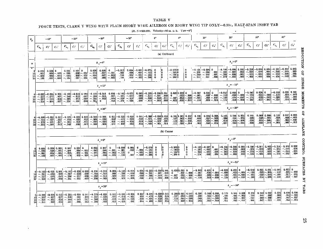
TABLE V
FORCE TESTS, CLARK Y WING WITH PLAIN SHORT WIDE AILERON ON RIGHT WING TIP ONLY--0.20c.4 HALF-SPAN INSET TAB
[R. N=609,000. Veloeity=80m. p.h. Yaw=0 °]
_T--40 ° --30 ° --20 ° --10 ° 0 ° 0 o 10 ° 20 °
c,_ c; cn' c_, c: c,.' cj, c; c : cj, c; co' ch, c; c'z c,_ c� cz c,, c; cz c_, c; cz c,,I
(a) Outboard
5 a=O ° _i =0°
I Cn p
P_
C_
a
o 0.059 0.008 0 0.035 ! 0.007 0 0.026 0.006 0 --0.012 0.004--0.001--0.670 0
I( .007 .009 --.002 _-.008 .008 --.001 --. 012 .007 --.001 .069 .004 --.001 --. ]43 0
1_ --.025 .009--.002 --.043 .0_ --.00_ --.056 .007 --.00_ •126 .004 --.OO1 --.185 0
20 --. 100 .007 --.003 --. 131 .007 --.00_ --. 145 .006 --.00_ .198 •003 --.00_ --.266 0
io1520
3 --0. 070 0
0 --. 143 0
D --. 185 0_) --.2660
,5a=15°--t
-0. 087 -0. 018 o. 0o3 -0.102 -0. 019 o. 004 -0.10_ -0. 018 o. 003 -0.14_ -0. 021 o. 005 -0. 2_ -0. o26 o. 005I--.227 --.017 .007 --.246 --.015 .007 --.232 --.014 •007 --.281 --•017 .008 --,351 --.021 .009--.292 -- 016 •008 --.286 --.012 •008 --.28 •012 .008 --.32£ --.0!5 •009 --.38_ --.018 .011
--.3101 --.004 .007 --.336 --.001 .008 --.33 0 .008 --.37f --.004 .008 --.41_ --.004 .008
_A=300
--. 010i--O. 180 --0. 006 O. 001 --0. 210 --0. 009 O. 002 --0. 221 --0. 010 O. 003
--.260 --.007 .002 --.300 .004 --.318 --.010 .005-- 289 --.006 .001 --.335 --.008 .004 --.35C --.008 .005
--_372 --.005 .003 --.408 --.005 .004 --.434l --.002 .005..
i
0 --0.124--0.004 0
0 --.205 --.004 .001
0 --.240 --.003 .001
0 --.315 --.001 .00_
5a =--15°
1_032 0 --0.017 0.026 0 --0.047 0.026 0 --0.047 0.026 0 --0.052 0.025 0.0010 03310 032 --. 00_ --. 061 .028--.005 --. 115! .02_ --. 00_ --. 134 .025 --.003 --. 150 . 024 --.002
--.027 .032 --.008 --.091 .025--.007 --. 146 •024 --.00_ --. 174 •023 --.005 --. 1_2 .023 --.004
--,052 .026--.011 --.116 .020--.010 --.174! .018--.00_ --.207 .017--.0Q7 --.225 .016--.006
_la=--30°
--0.308--0•05_ 0.0111--0.: 229 --0.025 0.010 --0•280--0.02fi O. 011 --0.323 --0.033 O. 011 --0.386 --0.035
--.344 --.027 .015; --.323 --. 023 .015 --.366 --.02_ .010 --.415 --.02_ .018 --.473 --.02_--.378 --.021 .017 --.361 --.018 .017 --.400 --.02_ •018 --.448 --.024 .019 --.504 --.02_
--.362 --.00l .012 --.346 .005 .012 --.389 .00_ .013 --.422 .00_ .014 --•466 --.001
0.013 0.266 _.051 0.007 0.196 0.050 0.006
• 019 • 157 .062 --. 00_ ,082 .057--•0_
.021 .113 .061 --.008 .060 .055--.008
• 014 .111 .030 --. 014 .053 .046 --. 014
0.142 0.04_i 0.005 0.14_ 0.050 0.00_ 0.128 0.047 0.006
. 069 . 054 --. 003 . O_ . 058 --. 003 . 090 . 050 --. 003
.019 • 05_ --. 008 .03_ • 055 --. 00_ .051 .055 --• 007001 .043! --• 014 .00_ .046 --. 014 --• 004 • 046_--. 013
I
O
O
O
©
(b) Center
_A_0 °
0._ o.0o80.00_I 0.051 0.007_0.001 0.022 0.007 0 -0.o05 o.oo4 0 [-0.070 01( --. 026 .006 -. 0011 --. 044 . OOfi -. 001 --. 045 .006 --. 001 -. 081 .002 --. 001 --. 143 0
15 --.081 .004 - 051 --•098 .OO_ --.091 .004 --.00_ --.122 0 --.001 --.185 0
20 --.16C .002--i002 --.178 .OOi -.002 --.164 .003 --.002 --.199 .001 --•002 --.2_ 0
-0. 023
--. 02(]
--. 02C
--. 00_
0. 0O_ -0.147
.00_ --.292
• 01C --.304
.00_ --.341
0-0.140
10 --.291
15 --•337
20 --.353
D --0. 0700 --. 143
0 --. 185
0 --.26_
_/=0 °
I0 --0.1251--0.007 0 --0.164 --0.008 0.001 --0.196--0.011 0.002--0.214 --0.013] 0.0020 --.197 --.007 .001 --.242 --.009 .002 --.273 --.012 .003 --.30_ --.0141 .004
0 --.234 --.007 .001 --.282 --.010 .002 --.318 --.013 .003 --.34{ --.015 .005
0 --.314 .00_ .001 --.362 --.0_ •002 --.382 --.004 .003 --.37( --.005 .004
_a=15 o 5A =-15°
00050t 100180•004_014500240004 00331 052000 0 00520•0 0I.009 --.252 --.015 .008 --.296 --.020 .008 --.351 --.021 .009 0 _ .032 --.00_ --.067 .026 --.004 --.099 .02_ --.004_
• 009 --. 290 --. 014 .009 --. 327 --. 019 • 009 --. 386 --. 018 . 011 --. 027 . 032 --. 00_ --. 098 .023 --. 006 --. 150 .021 --. 006
.009 --.338 --.003 .008 --.376 --.00_ .008 --.415 --.004 .008 --.052 .02_ --.011 --.120 .018 --.009 --.159 .017 -.009
--0. 026
--. 020
--. 017
--. 005
-0.050 0.023 0.001 --0.055 0.021 0
--. 130 .023--.003 --. 152 .021 --.003
--.165 .019--.005 --. 189 .017 --.005
--. 19_ .014 --. 008 --. 218 .013 --.007
0
©
C
t_
5a=30 o 5a =-30°
I
O. 210 t O. 049 O. 007 O. 224 O. 050 O. 006
.109[ .055 .00_ .088 .052--.002.047--.007
• 027 . 050 --.008 . 006 .041 --. 013• 001 .042 --.013 --.022
t_
--0. 303
--. 332
--. 360
--. 315
--0.03_
--. 027
--. 021
. OOi
0.013 -0.235
.017[ --.308
• 018[ --.344• 014! --.341
--0. 030 I
-. 0251
--•019
• 005
0.011 --0.279--0.033 0.011--0.336--0.038 0.013--0.386--0.03fl 0.013 O. 266 1.061 0.007 0.20d 0.046 0.006 0.1701 O 044 0 006
• 016 --. 357 --.029 .016 --.412 --.031 .018 --.473 --.02_ .019 .157 .06_ --.003 .10_ .055 --.002 .105[ "053 -- 002050--.007.017 --. 395 --. 023 .018 --.445 --. 02_ .020 --.504 --.02_ . 021 .113 .061 --.008 .049 .051 --.008 .031 "
.013 --. 384 .003 .013 --. 418 .001 .014 --. 460 --.001 . 014 .111 . 03_--. 014 .043 .045--.018 .011 .043 --. 013
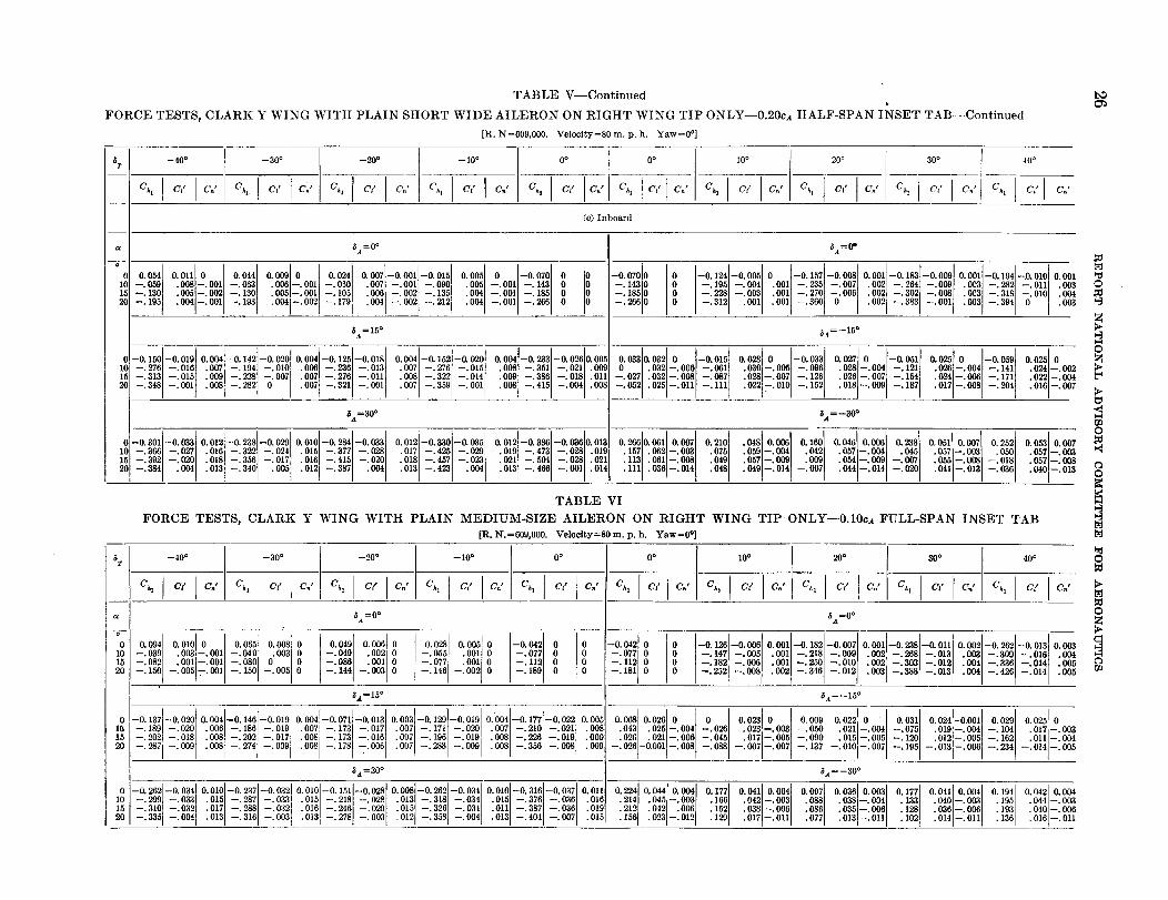
TABLE V--Continued
FORCE TESTS, CLARK Y WING WITH PLAIN SHORT WIDE AILERON ON RIGHT WING TIP ONLY--0.20c_ HALF-SPAN INSET TAB--Continued
[R. N=609,000. Velocity=80 m. p.h. Yaw=0 °]
bOO_
/it --40°
Ch I CI p
--30 ° --20 ° --I0 o 0o
CJ C h. C/ C:' C h C/ C,,' Ch, C/ C.' C h C/ 6".'
I OO
Ch I Cl I
20 ° 30 ° 40 °
C h C/ C." Ch_ Cl" CJ i Ch C/ C,;
(c) Inboard
a
-"K-
oi0
15
20
/i.,_ = 0 °
I I0.o54 0.011 0 0.044 0.oo9 0 0.024 0.007-0.001-0.015 o.oo_ 0 -0.070 0 i_--.059 •OO_ -.001 --.053 .006 --.001 --.050] .0071 --.00l --.090 .00_ --.001 --. 143 0
--.130 .00,5 -.OO'I --.130 .004 --.001 --.185 0 iO.OO5--.O01 --. 105 .00_ --.002 --. 135
--.195 .004 -.OOl -.103 .0041--.002 --.179 .004 --.002 --.212 .004 --•001 --•266 0 i _
t
$=15 °
I--0.150--0.01_ O. 004 --0.142 --0. 020 O. 004 --0.125 --0. 015 O. 004 --0.152--0. 020 O. 0041--0.233 --0. 026 0.006
--.276 --,Olf .007 --.194 --,010 .006 --.236 --.013 .007 --.276 --.015 ,OOSi --.351 --.021 .009--.313 --.01_ .009 --.228 --.007 .007 --.276 --.011 .008 --.322 --.014 •009 --.386 --•018 .011
--. 348 --.001 .008 --.28_ 0 .007 --.321 --.001 .007 --. 359 --. 001 .008 --.415 --.004 .008
5a=30°
--0. 301 --0.033 0.012 --0.238 --0. 029 O. 010 --0.284 --0. 03_ O. 012 --0. 830 --0. 035 O. 01_ --0.386--0•036 0.013
--.366 --.027 .010 --.322 --.024 .015 --.377 --.02_ .017 --.425 --.029 .01g --.473 --.028 .010
--.392 --.02( .018 --.356 --.017 .016 --.415 --.020i .018 --.457 --.023 .021 --.504 --.028 .021
--.384 .OO4! .013 --,34C .005 .012 --.387 .001' .013 --.423 .OO4 .013 --.466 --.OOl .014
t
/ix={)"
--0.070 0
--•143 0
--•185 0
--.266 0 =°ii0 --0.124i--0.006 0 :--0.157 --0.008 0.001 --0.183 0.001--0.194--D. 01CI O.OO]
0 --.1951 --.004 .001 --,235 --.007 .OO_ --.264 .OO3 --.282 --.011 .OO_
0 --.228i --.003 .OOl --.27G --.006 ,002 --.302 .003 --.318 .O1C .004
0 --.312! .001 .001 --.36C 0 .00_ --.383 •OO3 --.394 0 .00.2
/ia=--15 °
I --.00_g.0330.032_0 -0.015 0.0_0 -0.03_ o.o27o i-0.051 0.025o -0.050 o.o2_ o.032 •000 --.061 .03f 005 --.09_ .028 .004 --.121 .026--.004 --.141 .024
--•027 .032--•OO8 --.OO7 .02_ --.007 --.12_ .026--.007 --.154 .O.?A--.OO6 --.171 •02_i--.004
--.052 .025 --,011 --. 111 .02_ -.010 --. 152 .018 --.OO9 --.187 .017 --.008 --.204 .01¢I--.007
!
/i=--30 °
iO. 266 O. 061 O. 007 O, 21( .048 _0. _t O. 160 O. 046 O. 006 O. 238 O. 051 O. 007 O. 252 O. 053 O. 007.157 .062 --.003 .07_ .05g .042 .057 --.004 .045 .057[--.003 .050 .057 --.00.2
.113 .061 --.008 .04f .057 --_OOg! .009 .054 --.009 --.007 .055'--.006 --.018 .057 --.00_
.111 .036 --.014 ,048 .04(J --.014 --.007 .044 --,014 --.020 .041 --.013 --.036 .04(] --.01_
©
0
0
c_0
TABLE VI
FORCE TESTS, CLARK Y WING WITH PLAIN MEDIUM-SIZE AILERON ON RIGHT WING TIP ONLY--0.10ca FULL-SPAN INSET TAB
[R. N.=OO9,OO0. Velocity=80 m.p.h. Yaw=0 °]
_400
--30° .. --20°Ch I C/ I C ., C_, C� C:
--i0 o
Ch I
0o
Ca' _I O° "I 10°C/ CJ C_ C/
20 ° 30 ° 40 °
Ch, C/ CJ C/ CJ C_, C/ C? CJ C h C/ CJ
T _., =0 ° /i¢=0 °
o
0 0094100100 ooost 0008] 0040100o61 -°°281oo_o ooslo -_0_ -00420 0 -0120-00oo Oool-01s21-0ooT100011-0_1-0011100021-02021-00131000_10 --.030[__.082 "0011--'001"003--.001 --.080--'0491 0 '003 0 --•086--•040 .002, 0 --.077 •001,0 g 0 --.0770 0 --.147 -- 005 .0011 -- 218[- 009[ •002'--•2681--.0131 .003[--.300[--.016' .004.o01 0010 -:_12 - 11_0 0 -.1_2-.0o6.o01-.=0- 010.oo_-.3=I-.01_,.oo4,- _30,-•014,.00315 --.150 --.005 0 --.144 --.146 0 0 --.008 I20
--. 0051--. 001 --.150 --.003 0 -0020 _180 -131]00 i_.2521I•002_3_01_01_]0o31_388_-0131004I_4_01_0141005I 5a=15 o /i4=_15 o
0 01J-00_10oo41-01481-0019i00041-00711-001310.0031-0.129}-0.01910:oo41-01,7t-002210005'00680.0200 0 00=0 00090.0220 0.0310024-0.001002oo025010 ]_:1891 --.0201 .008] --.13_i --.0191 .0071 --.1731 --.0175 .0071 -.171/ -.020] .0071 -.2101 -.021] .008 .043 .025-.004 -.020 .02a-.003 -.050 .021-.00_[ --.0751 .0101-.0041 -.1041 .017,-.00315 --.2021 --.0181 .0081 --.202 --.0171 0081 --. 1731 -- 016I
20 --.287 i --.OO9 "008i--. 1781--'0061 .007 --. 196 --.019, .008 --.220[--.0191 •009 026 021- 006 --045 017- 005 --.090 015- 005 -- 120 012- 005 --102 011- 004--. 026 -6.001 --: 008 --: 088 --: 007 --: 007 --. 137 --: 010 --: 007 --: 195 --: 013 --: 006 --: 234 --[ 014 --: 005.007 --.288 --.009 .008 --.356 --.OO8 .OO9• 008] --. 274 --.009
I /i_=30° /i'4 =--30°
0--0.262--0•034 0.010f--0.237]--0.0321 0.0101--0.151i--0.028t 0.0081--0•2621--0.0341 0.010[--0.316[--0.037] 0.011 0.2241 0.044[0.0041 0.1771 0•0411 0.004 ] 0.097 t 0.036] 0.0031 0.1771 0.04110.OO41 0.1041 0.0421 0.004
10 --. 299 --.033 .015[ --. 287{ --. 0331 .0151 --. 2181 --.028[ .0131 --.3181 --.0341 .015[ --.376[ --.030] •016 .2141 .0451--.003[ .166[ .0421--.003[ .08815 --.310 --.032 .017 --.2881 --.032 .016 --.246[ --.029[ .015 --.3261 --.0341 .011 --•3871 --.030] .019 .212 .042 .006 •152 .038 --.006[ .086 "0381--'004[ .133] •040]--.0031 •1951 .0441--.003
• 035 --. 006 .1281 .036 --. 0061 .193 .040 --. OOO20 --.335 --.004 .013 --.316 --.003 .013 --. 278 --. 003 .012 --.358 --.004 .013 --. 404 --.007 .015 .150 .023 --.012 .129 .017 --.011 .077 .013 --.011 .102 .014 --. 011 .136 .016 --.011
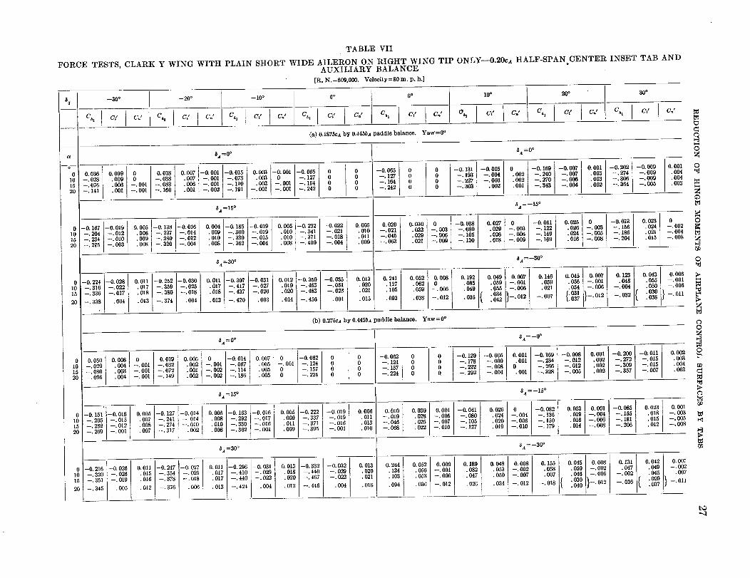
TABLE VII
FORCE TESTS, CLARK Y WING WITH PLAIN SHORT WIDE AILERON ON RIGHT WING TIP ONLY--0.20ca HALF-SPAN CENTER INSET TAB ANDAUXILIARY BALANCE
[R. N.=009,000. Velocity=80 m. p. h.]
_T
a
0
10
152O
--30 ° --20 ° --10 o0 o 10 ° 20 ° 30 °
CI t
Ck l C_' Cn / Ck t Cl v Cn' CAt CLP ] Cnt Cht l C_r Cnt Ckl I CIp Cnt C_t l Cn/ Chl I C_n Cn'
(a) 0.1875ca by 0.445ba paddle balance. Yaw=O °
_a=O o $a =0°
C
0.030
--. 028
--.076
--.141
0.069.009
.006
.001
0
0
--. 001
--. 001
0.018 0.007 --0.001 --0.015
--.038 •007 --.001 --.073
--.083 .006 --.001 --. 110
--.100 •001 --.002 --.191
$_=15 °
0.003 --0.061 -0.065 0
.003 0 --.127 0
.003 --.061 --.164 0
--•061 --•001 --•242 0
--0• 065
--.127
--. 164
--. 242
0 0
0 0
0 0
0 0
I
--0. 131
--. 193
--.227
--. 303
--0. OO5
--. 004
--. 003
• 002
0 --0.169
.002 --.240
.002 --.270
.001 --.343
5A=--15°
--0.007
--•007
--.00_--.004
O. 061
• 003
• 003
.002
--0. 202
--. 274
--. 306
--. 364
O
--0. 009 O. OOl O
--.009 .00<
--.009 .06'
-. 005 .o_
ffl
-0.167 --0.019 I 0.005 --0.138 --0.016 0.004 --0.185 --0.019 0.005 --0.232 --0.022 0.005
10 --.204 --•012 .008 --.237 --.014 .009 --.300 --.019 .OlO --.341 --.021 .010
15 --.234 --.010 .009 --.280 --.012 .010 --.330 --.015 .OlO --.371 --.018 .011
20 --.275 --.003 _ .008 --.320 --.004 .008 --.362 --.004 .008 --.400 --.004 .0091
55=30°
ioo15
20
0.020 0.030 0
--.021 .032 --.003
--.045 .029 --.006
--.063 •021 --.009
--0.038 0.027 0
--.080 •029 --.003
--.105 .026 --.006
--.130 . 018 --.009
--0.061 0.025 0
--.122 .026 --.003
--.149 .024 --.005
--.169 .016 --.008
6A=--30°
--0.224 --0.028
--.316 --.022
--.336 --•017
--.338 .004
0.011 --0.252 --0.030 0.011 --0.307 --0.031
.017 --.359 --.025 .017 --.417 --.027
.018 --.380 --.018 .018 --.437 --.020
.013 --.374 .004 .013 --.420 .003
0.012 --0.350 --0.035
.019 --•463 --.031
• 020 --.483 --.023
.014 --.456i .001
0.013
.020
.021
.015
0.241
•127
.105
•093
0.052 0.008
.062 0
.059 --.006
.038 --.012
O. 192 O. 049 O. 067
.085 { •059 }--.001
.040 .055 --. 006
.034 --•012• 035 • 042
_146
.059
•021
--.0_
0.045 0.007• 056 --. 001
.054 --. 006
.031
. 037 '--'012
--O. O73 O. 023 0 O
--. 156 .024 --. 00:
--. 186 .021 --. O0
--. 204 .015 --. O0
0.123 0.043 0.06
.048 .055 --.06
--.004 .O5O --.06
f •06Ol -.01038_
(b) 0.275Ca by 0.445ba paddle balance. Yaw=O °
5t=O o a_ =-0°oooooo oooooooooooooo o OoOlooooooooooolooooooloo--. 029 I .004 2. 001 .002 --. 001 --. 067 .005 .001 --. 124 00 00 --0. 062--.032 --.124 --•178 --.009 0.001 --.234 --.012 I •002 I --.272 --•015
--. 002 --. 114 . 005 I 0 --. 157 --. 157 0 222 --. 008 --. 266 --. _ . 002 --.309 I --. 015--i 096 • 005 --" 224 292 --. 004 --. --. 357 --. 007-- 080 .003 --. 001 --. 072 .001 --. 002 --. 186 0.004 --.001 --•149 .002 --.224 00 0 0 .001 --.328 .002
5.4=15 o 5.4=--15°
-0.151 --0. 018 O. 005 O. 065 --0, 016 O. 065 --0, 222 --0. 019 O. 006 O. 010 O. 030 O. OO1 --0. 041 O. 026 --0. 082 O. 023 O. 001 --0. 085
--.205 [ --.015 .007 --. 241 --. 014 .008 --. 292 --.017 .009 --. 337 --. 019 .011 --.019 .028 --.005 --.080 .024 0.004 --. 136 .019 --.004 --. 155
--. 232 I --.--"001012 ."007008 --. 274 --. 010 ."008010 --. 330 --. 016 ."009011 --.--' 395371 --. 016 .' 010013 --. 046 _ 002_ --. 007 --._. 127105 ."019020 --.--"006010 --.--" 179150 .' 010014 --.--"008006 --.--"206181
--.362 --.001.002 --. 010--. 317 --. 068--. 2691 - OOl5 =30 o 55 = --30 °
_0216-00 0.011-0247-002,0.011-0296-oo3110.013-o332-0o3210013o.244o.o52o.00901, 00,1o.o0801651o.o45o.oo80.131--. 320 --. 026 . 015 --. 354 --. 025 • 017 --. 410 --. 029 . 018 --. 440 --'--. 022029 ."021020 . 134 . 056 --. 001 . 082 ."050053] --.--"002007 ".007058 ".046050 --'--•006002 --." 047002
• 020.017.016--.351 --.019 --.378 --.018 --,440 --.022 --.467 .103 .053 --.006 .047
--.345 .012 --.376 .013 .004 .013 --.440 .004 .016 .094 .036 --.012 .020 .034 --.012 --•018 { •030
• 040 }--" 012 --. 036
• 005 ! .006 --. 424
O
O. 002 O
• 0O3
• 004
•003 C_0
• 018 --. O06 _
• 01g --. O05 _• 012 --. 008
t_
I}o• 049 --. 002
• 045 --. 007
• 029 --. 011• 037
--,I
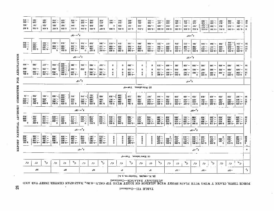
_10 "--_O0"--
IO0"
_00 "O
glO "--_O0"--L_O'--
0
OQ
L_O'--
0 _:00"
_O0"._ tO0 "0
o
980"61,0"
H_0"
8gO "0
g[O"Og0"gg0"_gO "O
g0O'
900"--
600"--I[0 "0_
100" 910 "--9_50" 1,00 "--
1,g0" IOO"
980 "O £00 '0
I1,g "- 810 '-I_,'-86I "- 000 '-80I "0-- l'OO "--
0
680'614)"
8_0'
OgO "O
9[0"-- 01,0" 880"900"-- 090' g£0"
I00"-- 8_0" 880"
9OO "O g£0"0 £60'0
_00'--IgO'.
I_l,O"
980 '0
_I0 "-- 610"
900"-- T,gO"1,0O "-- 9gO"
0 Lg0 "0
OI0" 'gig'--
EgO" _6I'--_0" 691"--]'gO @ I_I'0--
ogI--=v_
900"-- g0O'--
g00" g0O "--
0 I00 "--O _00 "0--
,,8_ l,oo_/goo/gO() "-- 988 '--
9Lg'-- g00" { LO0'--}"g'-g00.-
91,g "-- g0O" 900 "-- 0Ig '--98I "0-- IO0 '0 900 "O-- 8_I "0--
1,9I "--
II, I '-Lit "--LS0 "0--
oO=V_
L1,g "--
96I "--
19! "--_01 '0--
910 "-- I1,0"800"-- 1,90"
0 NO'
600 "0 1,g0 '0
910'-- 1,I0"
900 "-- 690"H)O'-- I80'I0O "0 OgO"O
0 0
0 O
0 00 0
990L6O
1O[
98[
911 "--
880"--9L0"--91,0 '0--
6Ig "--
8LI "--
_-_i .--990 "0--
OIOtgO
6tO
1,[0')
900'- 911,'- 600"990"- Lg1,'-- 0g0"
880"-- _6OW-- 810"
980"0-- 098"0-- OI0"O
8O0' _O0"--
Ol0" 810 "--600' gg0"--900"0 _0"0--
_[8"-- II0'
_68"-- 600"_9_'-- 800"9LI'O-- 900"0
0 6Ig'-- 800"-- IgO"
0 8LI'-- IOO'-- 900"
0 9gI'-- I00"-- gO0"0 990'0-- 1OO'0 -_ 900"0
1,00"-- 8L8"-- L00"990 "-- I68 "-- 910"
I_0'-- g9g'-- LI0"
9g0"O-- 808"0- gIO'0
oOS=r?
1,I0" gi8"-- IOO'
910"-- 6_g'-- 800"6tO'-- 1,Ig'- 900"ggO'0-- IiI'O-- BOO'0
o�I=r_
981'-- 800"--
680"-- I00"--
L1,0"-- I00"--900 "O 0
oO=V9
800"
LO0"
LO0"600 "O
900"
910"
II0"600 "0
,0=2a'_X 'uoaol!_ _s!.t_I (p)
I0"--gI0"--
0 ;O0'-Z) _IO'O
o
1_ gIO"
_60"_ 0
_00"
_ _60"_00 "0
800'
9LO"IfiO"690 "0
I00"- 810"-{i+ 190"990" } 910"
800" II0"-- 9LO" gI0"08[" _00"-- 6LO" gII"660'0 OIO'O 0L0"0 9gI "0
1,I0" lffI "--880" ggI'--LSO" _I'--_0'0 080'0--
900 '-- 0LS"--L0O'-- 01,g'--800 '-- Igg "--600 "0-- 06I "0--
810'-- I90' }690" 890"IIO "-- 090" 990"8O0"-- _80" _I"IIO'O gLO'O 09I'0
o08--=P8
gI0"-- LI9"010"-- 9_0"800"-- 690'
0 L80 '0
1,1I '--I0I "--00I'---_0 "0--
£I0 "--0tO "--900 "--
0
Og_"680"81,0"D0'0
990"--890'--990'--I00 "0--
o9I-- =v_
800" 1,00"--gO0 • 900"--gO0" _00"--I00 "0 L00 "0--
ISI "--99I "0--
gO0"gO0"IO0"IO0 "0
IO0"--I00"I00 "--gO0 '0--
gi8 "--0tI "--_8I "--8gI "0--
. , 690'810 8_0" . 0II"IIO'-- t,80" 860"_00"-- 900" £'9I"II0"0 9L0'0 _6t'0
1,I0"-- gg0" 600 "--IIO "-- Ill)" _00"L00"-- 91,0" 800"I00 "0 fl'0 "0 900 "0--
0 0 g/g'--0 0 ggI'--0 0 tS0"-0 0 L00"0--
_0"
990"_'g0"
(gO "0
II0"810"H0"800 "O
L00"
900"--910 "--0I'0 '0--
800"1,00"--_I0"--890 "O--
glg '-- IgO"
96_ '-- _0"091,'-- _'gO"001, "0 610 '0
968"- 010"098"- g[O"9_'-- 810"86I"0-- L00'0
g/Z, "-- 088['-- I00"--ZS0"-- I00"--L00"O-- IO0"0
800" 88_'-- 610"
800"-- I9_'-- OgO"£I0"-- 1,I_'-- _gO"8g0'0-- L98"0-- LI0'0
oO8=V_
010" 6_1,'-- 610"
IO0" 068"-- OgO"II0"-- 098"-- /,gO"9£0 '0-- _08"0-- 810"0
OIO" g68 "-
gO0' g_'--800"-- 1,18 '--g_0 '0-- t'gg '0-
1,00" I98"-- _00"
g00"-- I_98"-- 0T0"010 '-- 008"-- II0'
8gO'O-- 89I "O-- 900'0
ogI = v_
900" 969 '-- 600" 900" 699"--I0O" 8Lg'-- 010" 900" 6f,_'--900"-- L1,g'-- gI0" 800"-- 61,g'--_g0'0-- 8II'0-- 800"0 /,90"0-- 91,I'0-
gO0"L00"L00"00O "0
gig "--gL0 "--LI0"--900 "0
g00"-- 900"gO0 _-- II0'
N.o_ .6016 '0
oO=V_ oO=V_
o0=_.,I_ "oou_Itlq uaoH (o)
61,I "--I00 "--880"0(20 "0 l I00.O t'00' 08I"--
010" g00"--
IO0"O II0" 910"gIO'0 8L0"0
,"O ,tO ,to t*D
o08 [ o0goOI 1 ,"D ,to t*D
o0I --
,"_ ,to [ "_
o0g -- o08--
ooc_
['q "d "tu=g_ioo[o A "O00'OO9='/q "_I]
ponu!_uoo---XO_IWIV_ X_VI'IIXt'IV(I_IV aV,L _LXS_I _Ia,L_txO Nvas-a'IVrI rooa'o--k'I_tO alia; ONIA_ ,LHOI_t XO I_IO_IX'IIV X(IIAk ,L_OH_ XIV"IcI FI,LIAk OlqI/A k }I_IV'IO '_,L_ff_L XO_IOtI
ponu!_uoD--IIA X'I_i¥,L
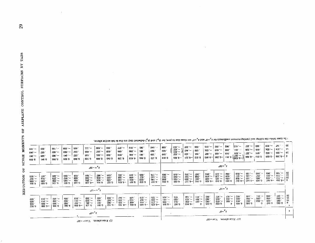
C',i
r_
©
00
Z
©
0 600 "-
_00 "--
IO0 "--
_00 "0
©
_; _o0"-LO0"-
lO0 "0T,O0 "--
600"£00"_00"gO0 "O
600"-- _0" III'-- 600"-- _0" LLO'-- OIO'-- I90" 9_0"-- 900" 910'-- { LO£'-- 000' 010"-- g_g'-- gO0' glO'-- LSg'-- gO0" OIO'-- L6I "-- O_
Lgo'-%l_,,--]_o.i_o._,] l',O'--OOl"--16IO" I_O'--{ggg'--,$IO" O-- l 0--{
_o" _i-_ _oo'- _o" _o-I_oo'- 6_o" _" soo'- ,oo' _o" _o" OI_0" _00 z_o- Is_- 1_o. I_0"-- { _0_'- SlO' OgO'-- L_'-- 010"
OIO "0 0- 6o, o,o o o: ,oo-o o o,o oO?olo o oo0_0 "0 gOl "09_0'i_0'0 09O "0 I800_"0 [ 000 "0 _0 "0 6_I '0
oOg- =vt' oOg = v_
{z,o" _'- _oo'- s,o" _o_'- _oo'- _ro," t_'- 6oo'- s_o" oz_'- _oo'- oto'- _o_'- _oo" _oo" _t'-I_o' soo'-]_t'- _oo'- _oo" {oot- o_
o,o. _:- _oo--o_o. o,_- _oo.-_o. o_,-- 6oo-- ,_o. _,,- o,o _o-- _.- _oo, o_06'°'-.-_,.-_,._O_Ooooo,o-"'°-l_'__:OO_oo-o-I_-"°'-'°"-I_--o_OgO" _00"-- I'gO' $Og'-- '300"-- 9gO" OOI'-- _00"-- 0_0" 90I'-- 800" £gO'-- OOg'-- LO0" LIO O-- _J'O'O-- _,00"0OgO'O _OI'O-- IO0"O L_O'O 9gI'O-- lO0'O LgO'O _LO'O-- IO0"O 67,0'0 L_O'O-- _00"0 _'gO'O-- LII O-- I-O0"O OgO'O-- 090"0-- EO0"O LIO'O-- i 61-0"0-- 0
ogI-- = v_ o_i= r'_ t
I'IO'-- I,II,'-- _00" gIO'-- 66_'-- LO0' gO0"-- LI,_'-- 60(V 6LO'-- OLd,'-- 910"-- _LO' $7.I '-- I lIO'-- I00' LLO'-- ttO'-- 800" 8_-0"-- II0"-- _O0" ! Io0"-- Og
g[O'-- BOg'-- gO0" IIO'-- gg_:'- IOO" LO0"-- _Lg'-- _[0' LgO'-- 6_'-- IIO'-- OF.O" _LO'-- { 100"-- _00" 8gO'-- I00"-- _-00' gO0"-- l_O0" _00" gO0'-- gI_00" LO0"-- ISg'-- 100" _00"-- _'-- 900" 910"-- F.LI '-- 900"-- _IO" _0"-- I00" gO0' g_ogIO'o'-- IO0'o l,O0" _00" 7,00"0 _00" tO0" OI
000"0- 0_[ '0- _00 0 SLO O- g_O'O- _00 0 .cO0"0 S_O'O LO0 '0 _SO "0 --2--°°600000.0_'- 90_6°_'0-'- ] too o got "0- ogt "0- t00"0 600 0- too'o- mo "0 0
oo=V_ oO=v_
o0_.-=_X "tlOaOl!t_o_!a,ff _(l) oO_=._t:X "tto._oi!u os!.U[ ,(o)
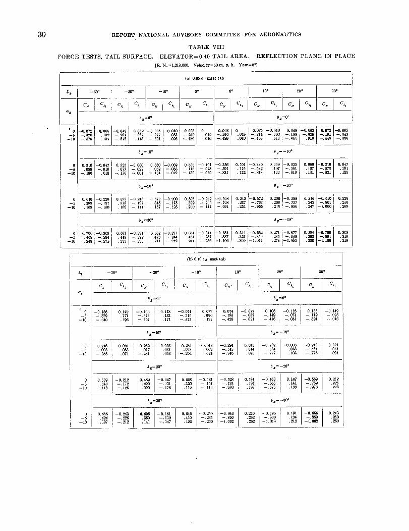
3O REPORT NATIONAL ADVISORY COMMITTEE FOR AERONAUTICS
TABLE VIII
FORCE TESTS, TAIL SURFACE• ELEVATOR=0.40 TAIL AREA. REFLECTION PLANE IN PLACE
[R. N.=1,218,000. Velocity=80 m. p.h. Yaw=0 °]
(a) 0.05 c$ inset tab
_8
° 0
--5
--10
0
--5
--10
0
--5
--10
0
--5
--10
C,v
--30 °
--0. 072
--. 320
--. 576
Ch|
6g=0 °
0,065 --0.049 0,062 --0.085 0,040
• 102 --.294 .087 --.277 .053
• 134 --. 6_8 .118 --.524 .096
6E= I0°
0 o
C v Ch,
--0.003{ 0
--. 240{ .010
--.480 I .040
[0 o
C N Ch!
0.003 0
--.240 .019
--.489 •040
10 ° 20 °
C_ C h CN C h
6B=O °
0.035 --0.040 0.049 --0.062
--.214 --.003 --.199 --.028
--.468 .013 --.461 .010
_=--i0 °
30 °
C N C h
0.072 --0.065
--.181 --.043
--.446 I --.000
0.310 -0.047
.059 -.010
--.190 .018
i --0. 1010.325 --0.060 0.330 --0.069 0.356 --0.356
--,022 .082 --.035 .116 --.078 --.591
--.164 --. 130 --.060 --.831.077 --.004 --.010--.176
I
0. I01 --0,330 I 0,069 --0.325 0.050 -0•310• 116 -- 582 . 107 --.581 .107 --.573
• 122 --:818 .122 --.810 .131 --•821
0.047
.104
.135
8s=20 ° 5B=--20 °
O. 610 --0.228
• 389 --.197
.169 --.150
O. 588 216 O. 572 --0,200 0.598 --0. 242 --0. 598
• 378 197 .345 --. 175 .392 --•206 --,798
. 160 144 . 157 --. 125 .200 --. 144 --.991
0.242 !--0.572
.237 --.763
.253 --.955
0.200 --0•588 0.216 --0.610
.206 --.757 .243 --.801
.216 --.986 .247 --1.000
0.228
•256
• 269
0•700 --0.303 0.677 --0.284 0.662 --0,271
.468 --.284 .449
• 240 --.275 • 233 --. 256 •211 --.219
5_=30 °
i --.8870.684 --0.314 --0.684
--.272 .423 --.244 .461 --.287• 244 --.256 {--1. 106
I
$ B=--30°
{O. 314 --0. 662 O. 271 --0, 677 O. 284 --0. 700
.321 --.859 .284 --•860 .293 --.884
• 309 --1.074 . 278 --1,085 .300 --1,106
0•303
• 319
.319
(b) 0.10 cs inset tab
&T --30° --20° -- 10° i0° 20° 30°
C N C h C,v Ch, C N C h C,v. Ch, C V Ch, C.v Ch,
c_8
5 g=O ° _ B=O °
-C--I0 --0. 136 0. 149 --0. 100 0. 118 --0. 074 0. 077 O• 074 --0. 077 O. 106 --0. 118 O. 136 --0. 149
--5 --. 379 .171 --. 346 .133 --. 316 .090 --. 183 --. 037 --. 149 --. 074 --. 119 --. (}03
-10 --.640 •196 --.607 .171 --.573 . .121 --.429 --.021 --.416 --.031 --.391 --.046
_B=IOO 6B=--10 °
0. 248 0. 021 0. 262 O. 003 0. 284 --0. 013 --0. 284 0. 013 --0. 262 --0. 003 --0. 248 --0. 021-- --. 003 . 053 . 017 . 034 . 043 . 009 --. 515 . 044 --. 534 . 063 --. 584 . 044
-- 10 --. 256 • 074 --. 231 . 043 --. 204 . 024 --. 746 . 075 --. 777 • 103 --. 776 • 094
_ =20 ° _g=--20 °
_o--lO
_0--I0
0.569
.340
.118
--0,212 0.489 --0.147--. 172 .290 --. 131
[ --. 125 .090 --.116r
0.528 --0.181
.320 --.157
• 119 119
--0. 528 O. 181
--. 734 .197
--.930
--0. 489 O. 147--. 685 .141
• 197 --• 875 . 138
--0.569
--. 759
--.973
0.212
•225
.228
8=30 o $B=--30 °
0.656 --0.243 0.595 --0.181 0.646 --0.250 --0.646 0.250 --0.595 0. 181 --0.656 0.243
.424 --.225 .360 --.150 .410 --.235 --.850 .262 --.800 . 194 --,860 .250
• 197 --. 212 . 141 --. 147 . 192 --. 200 --1.062 . 262 --1.013 . 212 --1.002 . 250
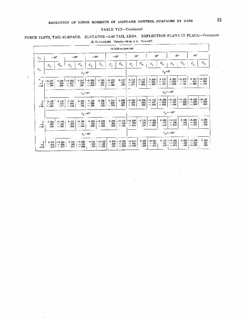
REDUCTIONOF HINGE MOMENTS OF AIRPL&NE CONTROL SURFACES BY TABS 31
TABLE VIII--Continued
FORCE TESTS, TAIL SURFACE. ELEVATOR=0.40 TAIL AREA. REFLECTION PLANE IN PLACE--Continued
[R. N.=1,218,000. Velocity=80 m. p.h. Yaw=0 °]
(c) 0.20 ca inset tab
i i I _1o°_:_,l _400I =800 2o0 I
a °s 0 --0. 263
_,v=O°
0.246 --0. 282 O. 212 --0. 206 O. 199 --0.113 O. 112
--.472 .205 --. 357 .121.130
--5 --.508 •258 --.457 .230 ! --.683 .22l--i0 l --. 766 .299 i --. 725 .261 --. 588
•-'-_ 6#=10° .0 0.1281 0.1181 0.155i 0.102 0.148[ 0.109 0.2t9
-.130 1 .143!-094q .121 -.088_ .[[8 .009--.384 17l I --.348 .149_ --.333! 130 --.238
0
-i8
0.009
.028
.037
_H=20°
b --0.082 --0.178
0.535 --0. 188 _ O. 513 --0. 166 ! O. 424 0.509 --. 153
I --.069 .284 --. 122.287 --.143 .0H'279 --.141 i .199 --.066 .090.036 --.085 --.055 .005
_=30 °
0.628=oi244• 416 234
.212 , 219
I
O. 464 --0.088 0.541 --0.150 0.613 --0.260
• 266 --. 100 .302 --. 125 .380 --.219• 074 --.088 . 106 --. 135 . 187 --.210
10 o 20 °
Cy Cht CN Ch,
30 °
C v Ch,
40 °
C x Ch,
_B=0°
O. 113 --0.112 0.206 I--0 199 0.282 --0.212 0.263 --0.246
i
--. 174 --. 208
--. 122 --. 087 --. 044 --i 17l --. 030 --. 127 .013--. 265 i 159
--.3711 --.050, --.3081 --.127 --.303
5B=--10°
--0.249 --0.009 --0.]48 t--0 100 --0. 155 --0.102 '--0.128 --0.118
--.482 .022 --.427 --_040 --.437 --.009 --.409 --.028
.013! --.694i .032 --.669[ --.028--.724 I .054 --.626
--0•509 _ 178 --0.424
--. 720 .188 --. 625--.914 .191 --.841
l
_E=--20°
o.082:ll° ::912
0.166 --0.535 O. 188
. 184 --.764 .210
.175 --.971 .219
5=--30 °
i--0.613 0.250 --0.541
--.836 .262 --.769
--1.042 I .256 --.973
O. 150 --0.464.18[ --.710
.178 --.914
0.088 --0.628 0.244
.132 --.832 .241
.122 --1.065_ .253I
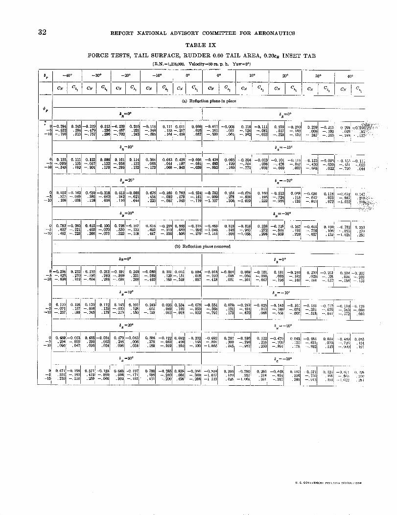
32 REPORT NATIONAL ADVISORY COMMITTEE FOR AERONAUTICS
TABLE IX
FORCE TESTS, TAIL SURFACE, RUDDER 0.60 TAIL AREA, 0.20cR INSET TAB
[R.N.=l,218,000o VelocityfS0m. p.h. Yaw=0 °]
_T
_F
o
--1C
--40 ° --30 o --20 ° --10 o 0 o 0o
CN C h CN G_ CN O h Cx Chz C_ Ch CN Ch
10° 20°
C_' C h CA, Ch
(a) Reflection plane in place
-0._4[0•2451-0.23910.210-0._010.2101-0.11610.1110.01110.00_--. 532l . 284 -. 479 . 236 --. 467 . 221 --. 348 • 133 . 02.5
-. 796! .313 -. 757 . 296 --• 585 .164.243 -• 217--. 702 --. 458 .057
_=10 °
I 0.1231 0.095 0.101[ 0.114 0.3041 0.0131 0.438[--0.09___ 0 155 0.111--.099 . 153 --.057 .132 . 12_ .044 . 197l --.061
• 192 .170 .152--10 --.345 --•058 .005--.301 .068--.045 --.039--. 173--.295
_a=20°
0 0.,_2_01420.6301-0.11,10.513t-0.0_o.076-0.16010.732-0._,--,'i .375 --. 040 .385 --. 0421 .342 --. 021 .454 .579 --. 161
.225 --,035 .345 --.119--10 .1081 .038 .128 .038 --• 092.110 .044
8=30 °
0 0.,_.732h0_ o.0151-0.10010.,281-0.16703101-0._81o._ -0.318_5 405_0 0, _133 212 292
--10 I .266 --.0751 --.200 .505 --•279• 322 --. 118
6R=0°
--0.011]--0.00310.1161 --0.11110.2391 --0,21010,239 --0.21510.299 "0_ _!_:_ _I!
--.201 .031 --.124 --•081 .017 --.182 .008 .029 --, 193:'_ j--. 245 1"--. 509 --' 192/• 061 --.382 --.033 "--.258 --. 132 --. --.--.145! 2481
<_R=--i0°
_._ 0•0951-0.3_1-0.0131-0.I011-0..41-0123i_00901_015;_0.i_--_ 892 .'169129 --.--"772554 ."093036 --.--"660426 --.. 007047 --.--"4501683[--'. 022039 --.--"7201451Ii --.. 0_0_
5R=--20°
I I--0. 78I O. 234 --0. 076 O. 160 --0. 51fi--.90fi .278 --.826 .195 --.724
--1. 107' .306 --1.019 .222 --.92_
0.0681--0.03010.1181 --_0!6_20.1_2• 115 --. 642 • 0531 .21 _,,:i_'
.135--. 843 i ', , _; ;'_?,
5R=--30°
-0 _ 0 318l-0 816[ 0 238.272
-104, :_-963 .6--1. 115 --1.038
--0,28[01671--0015]0101;0 _82[02_--.844 .193 --,726 .106! --.965i .27
--. 959 --1.028! .2_"1321 i.220 --.887
(b) Reflection plane removed
SS=0 °
05 --0.23410.232[--0.2100•213[--0.191[ 0.240[ --0.0301 0101[ 0.015 0.004
--i_3_ .270.312 --.--'396604.'240288--.--'369636 .231 --.269 , 129 --. 151 .018--10 --. 465 .057.268 . 69[--. 349
_o 0.11010.126 0.133--. 074 .157 --. 050
• 190 i--10 --,267 --.245
_tR=10°
o.11_01431o.10110.243i0025[03_1-00,8.131 --.--'219039 _128150 .055] .049 . 1661 --. 05317_ --. 1231 .053 --.018 --.032t
_R =20°
_00.,_:-006310.4351-0.06410_79T00_30_01-012210.6o2I_0202._ _009._6 .003,236-005 490_148095!.0541379_060 --.i00
•292--I0 .09_ .047 •095 ,054 --.019•189
6_¢=30 °
05,11-0123t0_31-0,0707801-0285083_-030,--5 .502 --.160 .412 --.090 .5081 --.171 .598 --.240 .664 --.3i
•302[ --.107.259 --.066 .431
0 0.671 --0.198
--I0 •330 --.116--. 200 .49fi --.2661
8R=0°
I r I I 1--0,015 --0.004 0.089[ --0. 101 0. 1911 --0.2401 0. 21( -0. 2131 0. 2341-0. 2_
--.095 I --.182 --. 198 .034 --,2C--.210 . 018 --.30l --.090 .005 --.140 .02_ --.157--.418 .051 --.057 --.198 --. L8t
--. 188 --.15
_n=--lO°
-0.3541 0.078 t -0. 243 t -0,025] -0.143[ -0. I01 -0,133[ -0. I12[ -0.110'[-0.12
-. 5681 . 121 -. 454[ . 013 -. 348 -. 074-.eel
--. 791 I, .175 - 67oI . 068 --. 563 --,--"518334 --.O4V--'075J --.--5721343]--.. 0006
_ =--20 °
-o59210.20_-05300.1221-047910.043-048_'00_41'• ' i079]--0.439j 0.05-.8Ol .3oo -.79_! .210 -.7031 _25 -.63, -.72, .,3.176 --.80_
--.891]--1.055 .345 --.981 .250 .110[ --.909! .19
5n=--30°
--0.838 0.366 --0.7801 0. 285 --0.6,t81 0. 197] --0. 5711 0. 1231 -i--0.67110. 19
--.935 .31_ --.854 .226 --,75i_
--1--1"017119 .425"419 -I. 06_ .166[ --. 865i .25. --t.0221--.9i31 2_.35 --.997 .266 194[ .
U.S. GOVERNMENTPRINTINGOFFICE:t931
_ve_
OlS2_
NL_", ,
....... ..c-:
eg _,il
,_ _':._,