TECHNICAL GUIDE FOR MECHANICAL SUPERVISORS … Course book.pdfDimensional parameters and weight...
99
. TECHNICAL GUIDE FOR MECHANICAL SUPERVISORS (REFRESHERS) OF INDIAN RAILWAYS SUPERVISOR TRAINING CENTRE KHARAGPUR INDEX UNIT DESCRIPTION PAGE NOS. FROM TO 1 LHB COACHES 2 5 2 FIAT BOGIE 6 11 3 CONSTRUCTION OF LHB COACHES 12 21 4 PNEUMATIC SUSPENSION 22 24 5 INJURY FREE FEATURES 25 26 6 BIO TOILET 27 29 7 CENTRE BUFFER COUPLER 30 39 8 RPC-4 40 41 9 FREIGHT STOCK 42 46 10 BMBS –WAGON 47 52 11 BLC WAGON 53 58 12 OBHS, CTS,IRCA .DRS CARD 60 61 13 FREIGHT TRAIN EXAMINATION PATTERN 62 65 14 TRAIN PARTING 66 69 15 CORROSION 70 71 16 WHEEL IMPACT LOAD DETECTOR 72 77 17 TRACK PARAMETERS AT A GLANCE 78 79 18 WELDING 80 96 1
Transcript of TECHNICAL GUIDE FOR MECHANICAL SUPERVISORS … Course book.pdfDimensional parameters and weight...

.
TECHNICAL GUIDE FOR MECHANICAL SUPERVISORS
(REFRESHERS) OF INDIANRAILWAYS
SUPERVISOR TRAININGCENTRE
KHARAGPUR
INDEX
UNIT DESCRIPTION PAGE NOS.
FROM TO
1 LHB COACHES 2 5
2 FIAT BOGIE 6 11
3 CONSTRUCTION OF LHB COACHES 12 21
4 PNEUMATIC SUSPENSION 22 24
5 INJURY FREE FEATURES 25 26
6 BIO TOILET 27 29
7 CENTRE BUFFER COUPLER 30 39
8 RPC-4 40 41
9 FREIGHT STOCK 42 46
10 BMBS –WAGON 47 52
11 BLC WAGON 53 58
12 OBHS, CTS,IRCA .DRS CARD 60 61
13 FREIGHT TRAIN EXAMINATION PATTERN 62 65
14 TRAIN PARTING 66 69
15 CORROSION 70 71
16 WHEEL IMPACT LOAD DETECTOR 72 77
17 TRACK PARAMETERS AT A GLANCE 78 79
18 WELDING 80 96
1

UNIT- 1: LHB COACHES
Indian Railways has entered in a contract (no.95/RSF/142/2 (GP-122)) with M/s.LHB, Germanyfor supply of modern light weight high speed coaches. The coaches are of air-conditioned typechair car and generator car, which are fit for operation at speed of 160 kmph. Coaches shall have aspeed potential of 200 kmph with suitable additions.
The coaches shall have the satisfactory performance means that Sprelling RI shall be preferablybelow 2.5 but not exceeding 2.75.The coaches shall be designed to conform to the principal dimension/ requirement given hereunder:
1. Track gauge = 1676mm. 2. SOD, IRSOD = 1676mm gauge of 1939 (Reprinted 1973). 3. Sharpest curve to negotiate = 175m. 4. Super elevation = 165mm max. 5. Min. Clearance above rail level = 102mm. 6. Pay load on AC coach = 8.0 T.
BENEFIT FROM LHB COACHES:-
1. Higher carrying capacity- these coaches are about two meter longer than ICF coaches. Thisextra length means two additional rows of chairs in chair cars of one additional way in sleepercoaches.
2. Better pay to tare ratio- LHB coaches shall weight approximately 40.3 tonnes. This weight isless than ICF coaches even with 2meter extra length.
3. Low corrosion- these shall be low corrosion on LHB coaches due to extreme usage ofstainless steel better design and manufacturing techniques.
4. Low maintenance- Replacement or removal of sub-system shall be required only after onemillion kilometres. These are no door handles projecting outside the coach and mechanisedcar washing in facilitated.
5. LHB coaches have authentically superior interior with GRP panels for side wall and roofpanelling. They can be removed easily for maintenance, resist water seepage and are wearresistance.
6. These are no visible screws inside the passenger compartments. 7. Higher passenger comfort- Ride index of 2.5 (not exceeding 2.75) has been specified. 8. LHB coach offers better passenger safety due to- Use of fire retardant material for
furnishing. • Provision of emergency open able windows. • Centre buffer couplers, vertically interlocked.
Visible door have thermal locking. 9. LHB coach offers better passenger amenities due to- A)More space for pantry.
B) Individual reading light in the chair car.
2

C) Ergonomically designed chairs with reclining back rest (seat bottom sliding featureprovided additionally for executive class chairs).
LHB COACH PARAMETRES1. Gauge 1676mm
2. Length over body 23540mm
3. Buffer centres 1956mm
4. Maximum width over body 3240mm
5. Height of the centre line of coupler from rail level 1105mm under tare condition
6. Height of compartment floor coupler from rail level 1303mm under tare condition.
7. Maximum distance between innerwheels 12345mm Maximum buffer drop under gross load worn condition 75mm
8. Maximum height of the centre line of side buffer 1105mm above rail level for empty vehicles
9. Minimum height of centre Line of side buffer above 1030mm Rail level for loaded vehicle
10. Maximum height of centre of screw coupling above rail 1055mm level for empty vehicles
11. Maximum axle load Permissible 16 tonne
CDTS UNIT LHB coaches are fitted with controlled discharge toilet unit to avoid swelling of track in stationand inhabited areas. Waste is stored in to an intermediate tank which is closed by a slide wallcontrolled by a microprocessor. The slide wall opens automatically at speed above 30KMPH.Toilet units are fitted with button operated flush valves, which flush with pre water usingcompressed air. Tanks have a capacity of storage of material for fifteen flushes and need to bebefore it can be used further. Lavatory ventilation system is to coach AC system of the coach through grills and exhaust fan.Exhaust fan opens in end wall to avoid suction of the soul smell in AC systems.
FLEXIBLE FOAM PADDED CHAIRSThere 78 chairs in the second AC chair cars and 56 chairs in executive class arranged in rows of 2and 3 chairs weight of a single chair for second AC chair car is approximately 21 kg against 28
3

kg in existing IR coaches. The chairs have lightweight aluminium frame seat cushion and backrest are made of fire retardant PU foam.
BRAKE SYSTEM a) Axle mounted disc brake with 2 disc per axle are used. This shall laid down maintenance
requirements of brake systems. b) 640mm*110mm discs. c) Condemning wheel dia of 845mm (New 915mm). d) Microprocessor controlled wheel slide protection device with all four axle controlled. e) Braking distance of 18 coach double headed train from a speed of 160 kmph is 1200 meter. f) Bogie level isolation for brake systems. g) EP brakes. h) Indicators to show that brakes are applied. i) Hand brakes only in power cars. j) All brake components are mounted in brake system. k) Cutting ring type of pipe fittings for air tightness. l) Stainless steel pipes for corrosion resistance. m) Independent brake cylinder for each disc. n) Asbestos free composition brake pads.
PASSANGER ALARM SYSTEMS a) Emergency brake application in the event of ACD. b) Air exhaust through 19mm chokes as per UIC. c) UIC pull handle. d) Pull handles are located on both the entrance walls of the passenger compartment and also
lavatories. e) Coupler forces are required to be within limit of the coupler strength.
DRAW AND BUFFING GEAR The coaches shall be provided with tight lock centre buffer coupler and anti-climbing feature andbe capable with AAR type coupler fitted on locomotive to IR Specification 56-BD-92.
SALIENT FEATURES OF LHB COACHES
These coaches are longer by 1.7 meters than the ICF coaches and hence more number ofpassengers can be accommodated in a given coach. As the length of the coach is longer thenumber of coaches required to form a formation is reduced and hence overall cost ofmaintenance becomes less.
These coaches are fitted with Axle Mounted Disc brakes to have an effective brake powerto stop the train within the emergency braking distance. As the brake forces are acting onthe Discs which are mounted on the Axles, the wear on the wheel tread caused due to treadbrake is eliminated and hence the life of the wheels are considerably increased.
These coaches are fitted with Wheel slide protection device to prevent the wheel fromgetting skid. Due to various reasons it is possible for any one of the wheel to have lesserspeed when compared to the other three wheels and in such a case it releases the air from
4

the brake cylinder of the affected wheel automatically to prevent the wheels from gettingskid
These coaches are fitted with Brake accelerator in the Brake pipe to bring BP pressure tozero during emergency brake application. The brake accelerator connects the Brake pipewith exhaust during emergency application to facilitate faster releasing of air from thebrake pipe.
These coaches are provided with FIAT bogies, which are designed to run at a speed of 160KMPH.
These coaches are fitted with Controlled discharge Toilet system designed to discharge thehuman waste when the speed reaches above 30 KMPH after completion of 15 flushing.The objective of this toilet system is to keep the station premises clean and hygienic.
These are fitted with tight lock AAR centre buffer coupler with anti-climbing feature toprevent the climbing of one coach over another in case of accidents.
The wheelbase of Bogie is 2560 mm.
These coaches are fitted with earthling device to prevent damages to the Roller bearings.
These coaches are fitted with roof mounted AC package units.
The following equipment’s are operated by electronically operated control system (Computer)
a. Wheel slide protection device. b. Controlled discharge toilet system. c. Water pumping device. d. Roof mounted AC package units
The riding index of LHB coach is 2.75 when compared to 3.25 in case of ICF Coaches
The passenger emergency alarms signal devices are provided inside passengercompartment. This is to avoid operation of PEASD by unauthorized persons from outside.There is no mechanical linkage like a chain and this handle directly operates the PEASDvalve for venting the brake pipe pressure.
5

----------
UNIT-2: FIAT BOGIE
DESIGN FEATURES OF BOGIE
The bogie frame consists of two side members of Y-shaped longitudinal beam connected bytwo tubular steel members. These members are connected by two channel shaped longitudinalmembers. The Y-shaped side members consist of structural steel sheet and welding is done toform box sections. Minimum strength of the structure is 52 Kg/mm² with class D weld. This is atwo-stage suspension bogie. The car body directly rests on the secondary stage helical springswhich rest on Y-shaped side beam. The bogie frame rests on primary stage helical spring whichare resting above the axle box crown. The traction and braking force from axle to bogie frame istransferred through articulated control arm system of primary suspension and traction and brakingfrom bogie to body is transferred through rocker arm device. Dimensional parameters and weightparticulars are given below:
1 Bogie wheel base = 2560mm.
6

2 Width of the bogie frame = 2240mm. 3 Height from rail level to top of bogie frame =925mm
(under tare load condition) 4 Mass of total bogie = 6330 Kg. 5 Secondary spring mass/bogie = 942 Kg. 6 Primary spring mass/bogie = 2611 Kg. 7 Un sprung mass/bogie = 3100 Kg. 8 Bogie Length = 3534 mm 9 Bogie Width = 3030 mm 10 Distance between bogie centres’ of the coach= 14900mm.
COMPARISON OF FIAT BOGIE, ICF BOGIE AND IR-20 BOGIE Features FIAT ICF IR20
Speed Potential (kmph) 160 140 160
Ride Index (max.) 2.75 at
180kmph
3.5 at
140kmph
3.0 at
160kmph
Bogie Weight (t) 6.33 6.5(16.25t) 6.8
Wheel base(mm) 2560 2896 2440 Inner axle distance (m) 12.34 11.89 12.33
Wheel dia new (mm) 915 915 890 Wheel dia worn (mm) 845 825 814
Axle box guidance Articulated Rigid Articulated
Dampers – Primary Hydraulic damper Dashpot Hydraulic damper
Deflection ratio S/P 67/33 50/50 66/34 Bogie frame Without headstock With headstock Without headstock.
Lateral stop Rubber Metal Rubber
Rubber compounds Many Very few. Less than Fiat, butmore than ICF
Brake Axle mounted disc. Conventional Axle mounted disc.
Bearing Taper Spherical Taper
Length over body (m) 23.54 21.34 21.77
Length over buffer 24.00 22.28 22.10
Seat capacity – I class
II class
52
78
46
67
48
70 No. of toilets 3 4 4
DESCRIPTION OF BOGIE COMPONENTS
PRIMARY SUSPENSION:-
7

It consists of an articulated control arm, nested helical coil spring and vertical damper. Thetraction and braking force from axle to bogie frame is transferred through the control arm.Part of the load on primary suspension is absorbed by elastic connection provided betweencontrol arm and bogie frame. Primary suspension characteristics are given below:
Outer spring Inner springMean coil dia (mm) 219 138
Wire dia (mm) 38 26
Free height (mm) 324 324.5
Vertical stiffness (N/mm) 4755% 2805%
No. of active coils 4.1 6.1 Total no. of coils 5.6 Radial stiffness Cx (N/mm) = 40000.00 Torsional stiffness Ct (Nm/rad) = 22800.00
7.6
SECONDARY SUSPENSION: It consists of nested flexi coil steel spring, rubber spring (both sides) and progressive rubber bellow spring. Progressive rubber is provided in parallel to coil spring for reduction of stresses in secondary spring in loaded condition in vertical direction. Secondary vertical damper connected with bogie frame and bolster to cushion the vertical movement. Secondary suspension characteristics are given below:
Outer spring Inner spring Mean coil dia (mm) 368 246 Wire dia (mm) 50 34 No. of active coils 5.1 6.8 Total no. of coils 6.6 8.3
Free height (mm) 707 663
Vertical stiffness (N/mm) 241.15% 129.55%
Lateral stiffness (N/mm)(gross) 164.5 31.1 Lateral stiffness of both rubber springs 180 N/mm.Lateral deflection of helical spring 28mm (gross) Total lateral deflection of sec. suspension 50mm (gross) Total lateral stiffness of sec. suspension 79.2 N/mm. Total lateral spring deflection 28mm under gross load
condition. Stiffness of minor pillow (each) 180 N/mm.
The characteristics of Rubber Pad and Rubber Bellow are given below: Rubber Pad : Free height = 90 to 95mm.
Inner dia. = 152 to 158mm Outer dia. = 225 to 238mm. Av. Ver. Stiffness = 9.4 kN/mm for installed ht. of 48mm.
Rubber Bellow : This rubber element having a progressive type characteristics whoseaverage value may be defined as 20 Kg/mm.
Max. vertical load capacity = 3200kg.
8

Max. vertical deflection =115mm.
Anti-roll bar : This is again a type of suspension achieved through the torsional movement of torsion bar.The stiffness of torsion bar supplement the secondary spring during the galloping/rollingmovement of coach. This torsion bar arrangement is used between bogie frame and coachbody. The anti-roll bar used in Fiat bogie is designed for tilting co-efficient of 0.3 with 50mmcant. The stiffness per half of the torsion bar = 1389.7 N/mm at 1330mm base. Verticalstiffness ratio of Anti-roll bar and helical spring is 0.546 and 0.454, at a base of 2240mm.
Rocker device : The traction and braking force between bogie and body is transferred through a rocker devicelocated at the centre of the bogie approximately in the plane of axle, in order to decouple thevarious vibratory movements consisting of rocker and a pair of thrust rod.
Body-bogie connection: A special type of body-bogie connection between coach body and bolster has been provided.This connection consists of disc spring, hemispherical ball, swinging link pin, link pin etc.This connection is capable to cater for the acceleration value upto 0.25g in lateral andlongitudinal direction. Beyond that value, a bracket capable to take 5g. Acceleration comesinto action between bogie bolster and coach body.
Brakes:The bogie is fitted with axle-mounted disc brakes (2 per axle). The disc size is selected insuch a way that wheels can be used upto max. Worn condition of 845mm dia. The size of thedisc is 640mm dia, with pads (both sides of disc) and pad holders with brake linkage. 10” diabrake cylinder is used with built-in automatic slack adjusters. Different parameters of brakesapplicable for Generator coach and Passenger coach are given below:
* Brake cylinder pressure for empty/loaded: 3.8 bar having built up time of 4 seconds.
* Brake cylinder piston force : 17857 N. * No. of brake cylinders per vehicle : 8
* Effective piston area : 510.7 cm².
* No. of brake pads per vehicle : 16
* Effective brake pad area : 400 cm².
* Cylinder volume (each) : 9.75 litre.
* Volume of auxiliary reservoir /vehicle : 125 litre.
* Co-efficient of friction between brake pad & disc. : 0.35
* Brake calliper ratio (for Gen. Coach) : 2.48 (for Pass. Coach) : 2.17
9
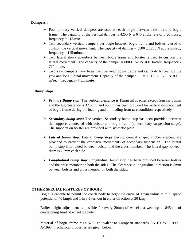
Dampers :
Four primary vertical dampers are used on each bogie between axle box and bogieframe. The capacity of the vertical damper is 4250 N ± 640 at the rate of 0.30 m/sec;frequency = 115/min.
Two secondary vertical dampers per bogie between bogie frame and bolster is used tocushion the vertical movement. The capacity of damper = 3500 ± 1200 N at 0.2 m/sec.;frequency – 115/minute.
Two lateral shock absorbers between bogie frame and bolster is used to cushion thelateral movement. The capacity of the damper = 8000 ±520N at 0.3m/sec; frequency -76/minute.
Two yaw dampers have been used between bogie frame and car body to cushion theyaw and longitudinal movement. Capacity of the damper = 11000 ± 1650 N at 0.1m/sec.; frequency- 7.6/minute.
Bump stops
Primary Bump stop: The vertical clearance is 13mm all coaches except Gen car 08mmand the lug clearance is 37.5mm and 45mm has been provided for vertical displacementof bogie frame during off-loading and on-loading from tare condition respectively.
Secondary bump stop: The vertical Secondary bump stop has been provided betweenthe supports connected with bolster and bogie frame (at secondary suspension stage).The supports on bolster are provided with synthetic plate.
Lateral bump stop: Lateral bump stops having conical shaped rubber element areprovided to prevent the excessive movements of secondary suspension. The lateralbump stop is provided between bolster and the cross member. The lateral gap betweenthem is 25mm each side.
Longitudinal bump stop: Longitudinal bump stop has been provided between bolsterand the cross member on both the sides. The clearance in longitudinal direction is 8mmbetween bolster and cross member on both the sides.
OTHER SPECIAL FEATURES OF BOGIE Bogie is capable to permit the coach body to negotiate curve of 175m radius at min. speedpotential of 40 kmph and 1 in 8½ turnout in either direction at 30 kmph.
Buffer height adjustment is possible for every 20mm of wheel dia wear up to 845mm ofcondemning limit of wheel diameter.
Material of bogie frame = St 52.3, equivalent to European standards EN-10025 : 1990 –A/1993; mechanical properties are given below:
10

Yield point = 355 for plate thickness <16mm. = 345 for plate thickness >16mm. UTS = 490.63 for plate thickness range >3 < 100mm.
Chemical composition of St.52.3 is given below: C = 0.23% by weight, Mn= 1.7%, Si= 0.6%, P= 0.045%, S= 0.045%
Permanent earthing connection has been provided to avoid the passage of operational currentthrough roller bearing.
Wheel slip protection devices have been used to protect against skidding of wheels.
Tapered roller bearing has been used with min. life rating = 2 x 10⁶ km, computed as per ISOpractice. The axle box is made in two parts to permit axle dis-assembly without removing thesuspension.
Wheel is IRS R19 and axle is IRS R16, wear adopted profile have been adopted.
New wheel condition = 915mm.
Condemning limit = 845mm.
--------
11

UNIT-3: SHELL CONSTRUCTION OF LHB COACH. The entire shell is made from stainless steel and low corrosion steel. All the structural elementswith section thickness above 5mm and more are made from Corten steel. Trough floor and roofpanels are made from members and sidewall panels are made from 1.25mm Austenitic stainlesssteel. Other structural members and sidewall panels are lightweight design of the coach. The shelldesign eliminates turn-under other pockets causing corrosion in conventional coaches.
The various types of steels used in construction of LHB Coaches.
Shell Assemblies Steels Used Composition
Side Wall, End Wall
And Roof structure
Ferritic Steel
X2 Cr8
C-.03%, Cr-10 to12%
Si-1%, Mn-1.5%
Roof Sheet and Trough floor Austenitic Steel
X5 CrNi18-10
C-.07%, Cr-18%
Ni-10%, Si-1%, Mn-2%
Under Frame Corten Steel
IRS-M-41
C-.01%, Cr-.35 to.6%
Ni-2 to 4 %,Si-0.3to0.7%
Mn-0.25%
COMPARISON THE CROSS SECTION OF SOLE BAR OF LHB COACHES WITHICF COACHES.
The C – Shaped section Sole bar is used in the LHB coaches when compared to Z-shaped
12
in ICF Coaches at the joint between the side wall and the under frame.
Necessity of providing of Tight Lock CBC in LHB Coaches : The LHB coaches are provided with Tight lock CBC with anti-climbing feature. Whenever there is
an accident, the Screw coupling of conventional coach first breaks which will result in climbingof one coach over another. This will affect the extrication work very badly in case of accident.This tight lock CBC will not break in the event of the accident, which in turn does not allow theclimbing of coaches, thus makes extrication works become easy.
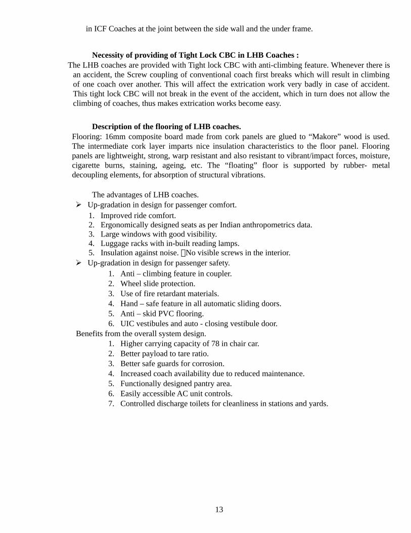
Description of the flooring of LHB coaches. Flooring: 16mm composite board made from cork panels are glued to “Makore” wood is used.The intermediate cork layer imparts nice insulation characteristics to the floor panel. Flooringpanels are lightweight, strong, warp resistant and also resistant to vibrant/impact forces, moisture,cigarette burns, staining, ageing, etc. The “floating” floor is supported by rubber- metaldecoupling elements, for absorption of structural vibrations.
The advantages of LHB coaches. Up-gradation in design for passenger comfort.
1. Improved ride comfort. 2. Ergonomically designed seats as per Indian anthropometrics data. 3. Large windows with good visibility. 4. Luggage racks with in-built reading lamps. 5. Insulation against noise. No visible screws in the interior.
Up-gradation in design for passenger safety. 1. Anti – climbing feature in coupler. 2. Wheel slide protection. 3. Use of fire retardant materials. 4. Hand – safe feature in all automatic sliding doors. 5. Anti – skid PVC flooring. 6. UIC vestibules and auto - closing vestibule door.
Benefits from the overall system design. 1. Higher carrying capacity of 78 in chair car. 2. Better payload to tare ratio. 3. Better safe guards for corrosion. 4. Increased coach availability due to reduced maintenance. 5. Functionally designed pantry area. 6. Easily accessible AC unit controls. 7. Controlled discharge toilets for cleanliness in stations and yards.
13

Wheel Slide Protection Device (WSP): In LHB coaches Air brake System with Disc brakes is used. During brake application,
factors like variation of co-efficient of friction (due to composition of brake blocks and disc) andadhesion between rail and wheels may cause difference in rotation of axles on the same coach.This may lead to wheel skidding/ flat tyres. To prevent this, a Wheel Slide Protection (WSP)device is provided in these coaches.
Main Components and their functions:
PART
No
NAME QTY FUNCTIONS
1. MicroComputer 1Per
Coach
Gets input from speed sensors, compares withreference speed and gives output signal to RapidDischarge Valve to open or close in case of variations.
G-I &
G-2
Speed Sensor 1Per Axle
It consists of a fixed Magnetic Resistor (MR) and aPhonic Wheel (P) having 80 teeth, fitted on the axle. Itgives tachometric pulse signal to Micro Computer dueto variation in air gap (A and A +X) between thephonic wheel and the magnetic resistor.
3. Rapiddischarge
valve (dumpvalve)
1Per Axle
It is an Electro-Pneumatic Valve which is connected inseries with the Brake Cylinder (BC). It regulates theBC (Part No-4) Pressure by disconnecting the DVfrom BC and also by connecting the BC withatmosphere when the output signal is received fromMicro Computer.
Principle: 14

The rotation of each axle is constantly measured and compared with a reference speed forthat coach. (The rotation of the fastest axle of the coach). In case there is a variation in rotationamong the axles, WSP automatically releases or applies the brakes accordingly, so that thespeeds of all the axles become uniform.
Working:
The limit of variation of speed and acceleration are defined as threshold values. The MicroComputer constantly compares the signals from the speed sensor mounted on each axle with thereference speed. If the speed/ acceleration of any axle is crossing the present threshold values, itgives signal to the respective Rapid Discharge Valve to vary the BC pressure accordingly, thusmaintaining the speed/acceleration within the threshold level
Schedule D1, D2, D3 should be carried out in depots as per following periodicity
Trip Schedule D1, Every Trip/ Weekly Monthly Schedule D2, 30 Days ± 3 daysSix Monthly Schedule/ D3 180 Days ±15days
Check visually the following for any damages/defects/deficiencies, it is to be done in D1 and D2both:
1. Destination board brackets. 2. Body panels.
3. End walls
4. Windows walls
5. Body side doors
6. Condition of head stock, sole bar and other under frame members.
D-3 (Periodicity D3 Schedule 180 days± 15 days)
• In addition to Schedule D1 & D2 do the following.
• Examine trough floor and other under frames from underneath for corrosion.
The detailed items to be carried out have been covered in chapter 12 of this manual.
Examination of Trains The examination is to be carried out as per RPC IV as amended from time to time. Examination of Originating Trains
i) All trains must be examined by the mechanical train examining staff before dispatch to ensurethat all coaches on the train are in fit condition and without reject able defects. On formationof a rake and after its placement for examination, washing, cleaning and watering, the StationMaster (SM) shall pass necessary memo to the Engineer (C&W). After carrying out allnecessary work, the Engineer (C&W) shall communicate fitness of the train to Station Master.Normally, Railways have standard forms for the use of Station Masters and Engineers for thispurpose. Railways, where such forms are not used, should also start using these forms as
15

uniform practice for the guidance of both Engineer (C&W) and Station Master. The StationMaster shall not dispatch the train unless the fitness certificate, in the prescribed form, isreceived from the Engineer (C&W).
ii) The level of the air pressure on the train engine and the brake van gauges and the percentageof operative cylinders should be recorded on a prescribed ‘Brake Power Certificate’ andsignatures of the driver and the guard of the train should be obtained by the Engineer (C&W)as per the procedure laid down by each Railway. A suggested standard format for thecertificate is placed at Annexure ‘C’. No train should be allowed to leave with aninoperative/defective brake cylinder on any coach after pit attention. Trains which have beenattended on pit line should have 100% brake power.
Enroute/Terminating Examination of Passenger Trains
i) Sr.DME/DME in charge shall nominate the site for carrying out rolling in/rolling outexamination after personal inspection of site. While nominating the site following should bekept in view:
a) Site shall provide unobstructed view of under gear from both sides
b) Speed of the train shall not be more than 30 KMPH.
c) It should cover the entire length of train.
d) Should have adequate space for fixing the lighting arrangement and for staff.
ii) For rolling in examination of train it has to be ensured that proper lighting arrangement isprovided on both the sides of the track at nominated spots for examination of under gearparts during night. Focusing of lights shall be done by keeping a coach on the line andadjusting the angle of light to illuminate under gear and bogie. Use of fixed lights asindicated in figure 1.4 is preferable.
iii) C&W staff should take position at nominated rolling in place on both the sides of the trackbefore the arrival of train.
iv) As the train passes the nominated point, C&W staff should watch out vigilantly forloose/hanging/broken under gear parts of the coaches, any unusual sound coming from thecoaches or any other abnormality in the coaches.
v) After train comes to halt, it should be ensured that the train is protected from both the sides(with the stop board/red flag during day time and red lamp during night time) beforecommencing the examination of the train. It should be ensured that a suitable indicationboard is placed at conspicuous location visible to the driver indicating that C&W staff is atwork.
vi) Temperature of the axle boxes should be measured preferably with the help of the electronictemperature measuring device.
• Brake release shall be checked physically. However, in case where train locomotive has tobe changed, brakes of all coaches shall be manually released after attachment of loco.
• Other under gear parts should be examined visually to ensure that the train is safe to runfurther. During night the lamps/search light shall be used for illumination.
vii) Repairs if required should be carried out promptly to avoid detention to train to the extentpossible.
viii) Lavatories of the coaches should be properly cleaned using High pressure waterjet machine provided at nominated stations during halt of the train. Anycomplaint from passengers should be attended promptly to the satisfaction of thepassenger.
ix) After attending to any required repairs stop board/red flag should be removed. x) Carriage controller (CCR) should be informed about any out of course work done.
16

xi) CCR shall repeat the out of course work done to the Primary Maintenance (PM) depot aftercorrective action.
xi) At the train examination stations where locomotives are changed on through trains, the levelof air pressure created on the locomotive and brake van gauges should be recorded on thecertificate to be issued to the guard and driver on prescribed form. The inoperative/blankedcylinders, if any, should also be written in the certificate for their information. Thiscertification should be an endorsement on the original brake power certificate; no freshbrake power certificate needs to be issued.
AIR BRAKE RAKE TESTING PROCEDURE (LHB COACHES)
1. On arrival of the rake on pit line, completely drain the AR tank (125 litres & 75 litres) ofall the coaches by opening the drain cock, to remove the water in air.
2. Initially, couple the BP hose of the test rig with the BP hose of the rake & then charge theBP pressure to 5.0 kg/cm2. Keep the FP angle cock of both end power cars in closeposition. Check the FP gauge fitted in the power car, if the gauge does not show anypressure, the NRV of all the coaches are ok. If, FP gauge shows any pressure, the NRV ofany coach in the rake is defective. In this condition, check the rake for NRV defective bytaking the coaches in parts. NRV found defective in particular coach should be replaced.
3. Open all the four cocks of rake, couple BP & FP hose pipe of test rig with the BP & FPhose pipe of the rake. Charge the BP & FP to 5.0 kg/cm2& 6.0 kg/cm2 respectively. Afterbuilding of pressure in BP & FP, disconnect the test rig BP & FP hose pipe from the rake Hose pipes & open both the angle cocks, due to which air pressure will be exhausted inatmosphere & brake will be applied. Wait for 20 to 25 minutes.
4. After 20 to 25 minutes, check the complete rake from one end. Note down the coach nos. found with release brake cylinder. Check whether, AR tank of the coach is charged orempty. If AR tanks found empty, write down Empty AR on the respective coach. If foundcharge, pull manual release of DV to check whether CR tank is charged / empty. If CRfound empty, write down Empty CR on respective coach. With this, all the defects in therake can be checked.
5. Again, connect BP & FP hose pipe of the rake & test rig & then charge BP to 5.0 kg/cm2 &FP to 6.0 kg/cm2. Connect BP & FP gauges with dummy on free end of other power car.
6. Check the BP & FP pressure gauges in front power car, BP pressure should show 5.0kg/cm2 & FP pressure should show 6.0 kg/cm2. If there is any difference in any pressure,check by fitting master gauge if still the pressure is not showing 5.0 kg/cm2 in BP & 6.0kg/cm2 in FP, check for leakage & attend.
7. Close the BP & FP angle cock of test rig for 03 minutes. Monitor the leakage in both BP &FP. The leakage should not be more than 0.6 kg/cm2 in 03 minutes.
8. Attend the coaches in which AR empty & CR empty are found. Check the AR tank & pipeline from the back of the brake panel for leakage. Similarly, check CR tank & pipe line &dummy plug on the brake panel. If defect is still noticed after attending the leakage, thanmark the coach sick for detailed investigation & single car testing in sick line.
9. Start the pressure & charge the BP to 5.0 kg/cm2 & FP to 6.0 kg/cm2. Drop the BP pressureby 1.6 kg/cm2, brake should apply in all coaches. Start the leakage checking with the helpof soap solution from one end. During soap solution testing, check all the BP & FP hosepipe, all hose pipe connectors, Main pressure pipe line, Angle cocks, Brake cylinder pipeline, CDTS pipe line. Similarly, check & attend leakage in components on Brake panel likeDV, FP & BP filter, NRV, all isolating cock, brake indicator, brake accelerator & brakecylinder with soap solution.
17

10. Isolate the isolating cock on Brake panel & check all brake callipers& brake pad of allcylinders. In isolated condition, all brake pads should be released simultaneously.Similarly, on opening of isolating cock all Brake cylinder should operate & brakes shouldapply.
11. Check the brake indicator when brakes are applied, indicator should display red colour.However, when the brakes are released from isolating cock the brake indicator shoulddisplay green colour. If on brake release condition, brake indicator is not showing green oron brake applied condition brake indicator is not showing red, then the brake indicator isdefective. Repair / replace the brake indicator.
12. The BP & FP pressure gauges in the others end power car should show pressure 3.4kg/cm2 & 5.8 - 6.0 kg/cm2 respectively. If any difference in above pressure is noticed thatmeans there is any cross connection in BP & FP connection. Attend the same & ensure BPpressure 3.4 kg/cm2 & FP pressure 5.8 - 6.0 kg/cm2.
13. Charge the BP & FP pressure to 5.0 kg/cm2 & 6.0 kg/cm2 respectively. Check the brakeindicator of complete rake, all coaches should be in released condition. If any coach is notreleased, it means that the CR of that particular coach may be overcharged & there is aninternal defect in DV. Mark the coach sick for detailed investigation.
14. Check PEASD of at least 03 coaches. During PEASD checking, brakes should apply in allcoaches & the brake accelerator should operate. Coach numbers should be noted inmaintenance dairy.
15. Now closed the pressure supply from the test rig. Operate the emergency guard van valveof front power car guard van. BP pressure should become 0.0 kg/cm2 in approx. 25 to 30sec in front power car & approx. 40 to 50 sec in rear power car. Open the pressure supply & charge BP & FP to 5.0 kg/cm2 & 6.0 kg/cm2 respectively. Now again closed the pressuresupply from the test rig. Operate the emergency guard van valve of rear power car guardvan. BP pressure should become 0.0 kg/cm2 in approx. 25 to 30 sec in rear power car &approx. 40 to 50 sec in front power car. Check for any significant difference in time for droppage of BP pressure to 0.0 kg/cm2
between front & rear power cars. If any, there may be blockage in BP line of any coach. Iffound, attend the same. Continuity test of the rake is now completed.
16. In both the power cars, check the condition & mounting of hand brake cables fitted onboth the brake cylinders. Rotate the hand wheel fitted in guard van clockwise to apply thebrakes, after full rotation brake should apply in both the brake cylinders & hand brakeindicator should show red. Rotate the hand wheel anti clockwise, now brakes of both thecylinders should get release & hand brake indicator should show green.
17. Charge the BP & FP to 5.0 kg/cm2 & 6.0 kg/cm2 respectively. Close the BP & FP anglecock of test rig for 03 minute. Monitor the leakage in both BP & FP. The leakage shouldnot be more than 0.6 kg/cm2 in 03 minutes.
18. Isolate the isolating cock of BP & FP of the test rig & angle cock of BP & FP of the cock.Uncouple both hose pipes & open both the angle cocks of coach. After draining ofpressure from both the BP & FP hose, release the complete rake by pulling the manualrelease handle of the DV of each coach & ensure the brake indicator of all coaches shoulddisplay green color. Ensure that all BP, FP & BC gauges fitted in power car are calibrated& showing correct reading.
WSP Testing
18
1. Initially with no pressure, the WSP processor in all the coaches should be OFF. If anyprocessor is in ON condition, there is problem in any of pressure switch, wiring or K-05relay. Attend the same.
2. Start the BP & FP pressure. The processor should automatically ON when BP pressurereaches 1.6 to 2.0 kg/cm2 in M/s KNORR WSP system & when FP pressure reaches in M/sFTIL WSP system.
3. Check & attend for loose/proper fitment of WSP components like speed sensor, junctionbox, dump valve, dump valve connector & pressure switch.
4. Drop the BP pressure by 1.6 kg/cm2, brake should apply in all the coaches. Now check theWSP processor for correct reading ‘99’ on the electrical panel inside the coach. If thereading shows ‘99’, it means that the WSP system is OK. Operate the test button on theprocessor to check the proper working of dump valves. The dump valve should operate ina sequence & pressure should be exhausted from brake cylinder. If the dump valve is notoperated in proper sequence attend the same. Similarly, check & attend the WSP system ofall the coach. All the WSP system should be in operating condition in the rake.
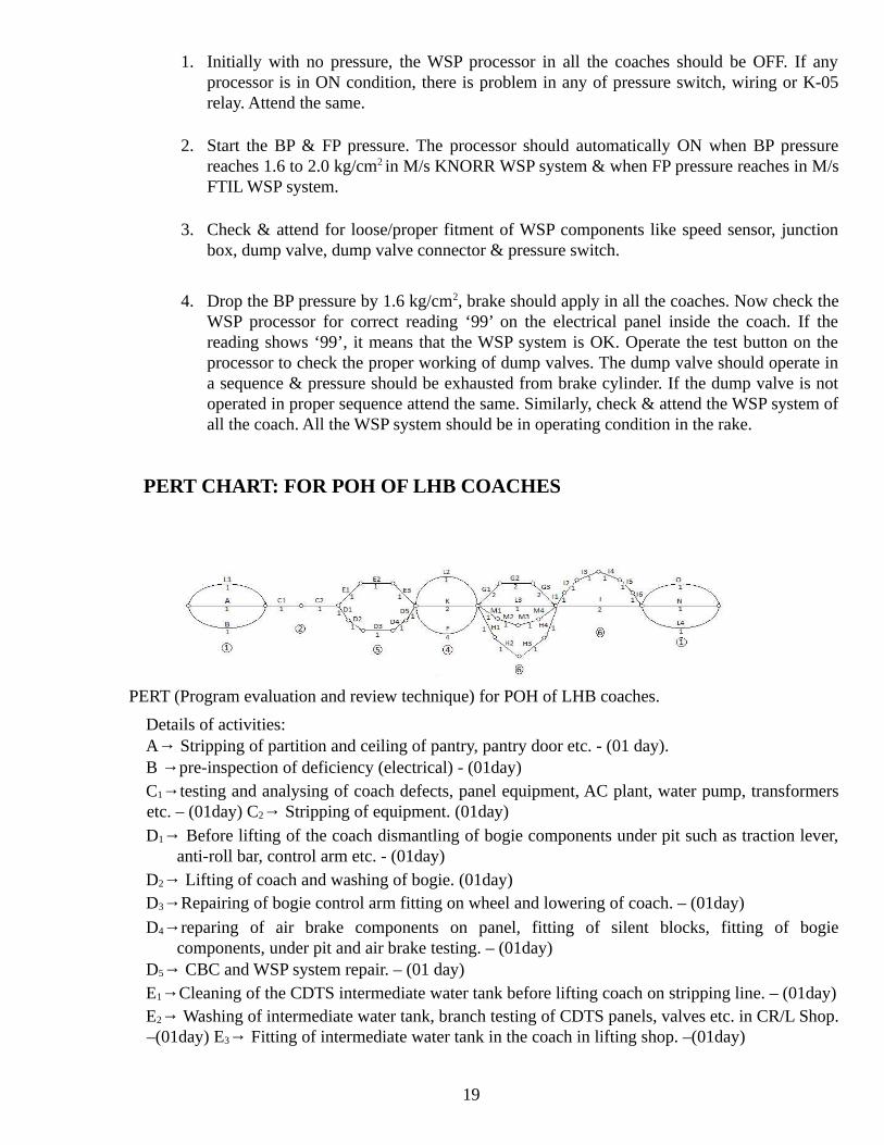
PERT CHART: FOR POH OF LHB COACHES
PERT (Program evaluation and review technique) for POH of LHB coaches.
Details of activities: A→ Stripping of partition and ceiling of pantry, pantry door etc. - (01 day). B →pre-inspection of deficiency (electrical) - (01day) C1→testing and analysing of coach defects, panel equipment, AC plant, water pump, transformersetc. – (01day) C2→ Stripping of equipment. (01day) D1→ Before lifting of the coach dismantling of bogie components under pit such as traction lever,
anti-roll bar, control arm etc. - (01day) D2→ Lifting of coach and washing of bogie. (01day) D3→Repairing of bogie control arm fitting on wheel and lowering of coach. – (01day)
D4→reparing of air brake components on panel, fitting of silent blocks, fitting of bogiecomponents, under pit and air brake testing. – (01day)
D5→ CBC and WSP system repair. – (01 day) E1→Cleaning of the CDTS intermediate water tank before lifting coach on stripping line. – (01day)E2→ Washing of intermediate water tank, branch testing of CDTS panels, valves etc. in CR/L Shop.–(01day) E3→ Fitting of intermediate water tank in the coach in lifting shop. –(01day)
19

F→ Stripping of lavatory ceiling, repair of lavatory door, repairing vestibule door, cushionstripping, repair of recycling gear, foot rest, snack table, stripping of the fittings viz. bottleholder, mirrors etc. –(4days)
G1→ Loading of all equipment except RMPU. (02days) G2→ RMPU loading, loading of pantry equipment etc. –(02days) G3→ Complete testing, fault diagnosis and their remedy. –(2days) H1→Stripping and fitting of window glasses, flooring work etc. –(01day) H2→Repair and fitment of salon sliding door, roller blinds etc. –(01day)
H3→Repair and fitment of entrance door, electrical panel door etc. –(01day) H4→Fitting of pantry partition, ceiling, pantry doors, lavatory ceiling, other fittings etc.–(01day) I1→Washing with suitable detergent –(01day) I2→Application of putty –(01day) I3→Rubbing down putty and application of surface. –(01day) I4→Window masking, roof painting, end painting and painting of side panels leaving down side
area. –(01day) I5→Masking of upper area and down side painting.–(01day) I6→Removal of masks, touch tip, lettering, cleaning and other works.–(01day) J→ Internal painting K→ Body panel repair, stripped body repair, repair of inner members like partition frames, chair
angles and seat supports etc. –(02days) L1→ Stripping of curtains in stripping line. –(01day) L2→Stripping of seats in carriage AC shop.–(01day) L3→Fitting of seats and curtains in coach.–(01day) L4→Cleaning of seats and other activity.–(01day) M1→Testing of under slung/Overhead water tank in CR body/CR AC section.–(01day) M2→Repair and testing of water tank in plumbing shop.–(01day) M3→Fitting of water tank in coach.–(01day) M4→Fitting of CDTS panel in coach in CR body/CR AC shop.–(01day) N→ Final Inspection and Despatch.–(01day) O→ Final Air Brake testing.–(01day)
POH Chart for ICF Coaches:-
20

Activity Description:
A. Verification of deficiencies.–(01day) B. Pre-Inspection and lifting.–(01day) C. Stripping.–(02days) D. Body repair, modification and alteration.–(03days) E. Painting.–(09days) F. Fitting of water tank, plumbing and leakage testing.–(03days) G. Repair of interior panels.–(03days) H. Fitment of shutters.–(02days) I. Fitment of doors.–(01day) J. Fitment of berths and seats. –(03days) K. Vacuum/Air Brake testing and final works.–(01day) L. Final Inspection and Dispatch.–(01day) M. Fitment of axel pulley, tension rod and testing of coach wiring. –(01day) N. Testing of
branch wiring and fitment of electrical equipment.–(09days)
-----------
UNIT-4: PNEUMATIC SUSPENSION Why needed---in sub urban trains the number of passenger entering into the coach cannot becontrolled and due to this the payload of the coach increased from 18 tonnes to 34 tonnes, thisabnormal increased in pay load creates following problems for safe running of trains-
Riding clearance between coach body and wayside platforms reduces and this may cause grazing ofcoach body, or wheel flange touching coach under frame.
Buffer height and buffer height of the coach also reduces considerably. These defects may causederailment or serious accident
These trains runs with huge nos. of passengers during morning & evening whereas in daytime theyruns with minimum nos. of passengers. If we provide spring suspension according to morning loadthe passengers feel discomfort during daytime whereas if we provide spring suspension accordingto daytime load the cases of breakage of spring will be more during morning run.so we need aneffective suspension system for varying conditions of loads.
In coaching stock coaches load is classified as under – Dense crush load (DCL)= seated capacity+200% of sitting as standing
Practical dense crush load (PDCL) -------- seated capacity + standing load@ 12 person per sqmtr.
Super dense crush load (SDCL)--------- seated capacity + standing load@ 16 person per sqmtr.
Due to SDCL the bolster spring becomes solid, which inturn damages, breaks the coil spgs.resulting in discomfort to passengers.
Pneumatic suspension or air spring has been invented to resolve this problem.
Air spring- Air spring is a rubber bellow containing pressurised compressed air with anemergency rubber spring providing various suspension characteristics to maintain a constantbuffer height and floor height irrespective of loading conditions.
21

Pneumatic suspension has been provided in secondary suspension in coaching stock. Presently
Indian Railway is using four types of air springs namely
180 k N - for EMU/DMU/MEMU Motor coach 150 k N – for EMU/DMU/MEMU Trailer Coach 140 k N - for Main Line, Rajdhani, and Double Decker Coaches 130 k N – for
hybrid coaches 120 k N – for LHB fiat bogies. Main parts of pneumatic suspensions
Air spring with emergency rubber spring 04 nos Levelling valve 04 nos:- with ±2.5 degree dead band region Installation levers 04 nos Duplex valve 02 nos Main reservoir 150 ltrs capacity Additional reservoirs 04 nos Isolating cocks Air filters Non return valve Wireless failure indication cum brake application (WFIBA) valve
22

Advantages of pneumatic suspension
Capable to sustain SDCL in suburban traffic at high speed. Maintains constant buffer height and floor height. Safe running due to excellent air damping. Double decker coaches with RMACPU could be possible due to low design height
Working of Pneumatic Suspension: Equalization in sick line we maintain buffer height, floor heightand air spring inflating height and according to it the position of installation lever has been set in thiscondition of the rotation arm of levelling valve remain in horizontal position and the pressure in airbellow should be minimum 5kg/cm2
23
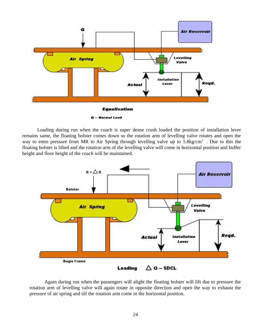
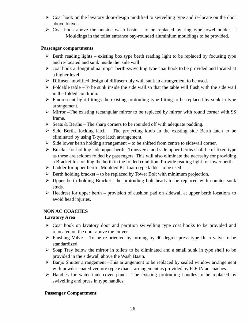
Loading during run when the coach is super dense crush loaded the position of installation leverremains same, the floating bolster comes down so the rotation arm of levelling valve rotates and open theway to entre pressure from MR to Air Spring through levelling valve up to 5.8kg/cm2 . Due to this thefloating bolster is lifted and the rotation arm of the levelling valve will come in horizontal position and bufferheight and floor height of the coach will be maintained.
Again during run when the passengers will alight the floating bolster will lift due to pressure therotation arm of levelling valve will again rotate in opposite direction and open the way to exhaust thepressure of air spring and till the rotation arm come in the horizontal position.
24

---------
UNIT-5: INJURY FREE FEATURE
INTRODUCTION
“CRASH-WORTHINESS” is achieved by making the interior parts of the coach in such away that injury to passengers is minimized in the event of a minor collision or derailment or anyother type of accident. When the passengers are thrown about, they hit the interior parts of thecoach. At that point of time, the sharp corners and edges of the fittings and upholstery of the coachcause grievous injury to th4e passengers. They are also injured by falling luggage. In an effort tominimize the risk of such injuries many features are provided in the interior fittings of coaches.
Following injury –free features will be adopted in coaches:-
AC COACHES Lavatory Area:
Tray below mirror in lavatory to be eliminated and soap tray above wash basin relocated topartition side above the wash basin.
Shelf at the side wall side in lavatory –To be sunk inside the side wall. Flushing valve – to be re-oriented by turning 90 degrees. Press type flush valve to be
standardized. Flushing Valve in Western Type Toilet –Plumbing arrangement shifted from side wall to
corner. Toilet paper Holder – to be sunk inside the end wall with flap cover.
25
Coat hook on the lavatory door-design modified to swivelling type and re-locate on the doorabove louver.
Coat hook above the outside wash basin – to be replaced by ring type towel holder. Mouldings in the toilet entrance bay-rounded aluminium mouldings to be provided.
Passenger compartments
Berth reading lights – existing box type berth reading light to be replaced by focusing typeand re-located and sunk inside the side wall
coat hook at longitudinal upper berth-swivelling type coat hook to be provided and located ata higher level.
Diffuser- modified design of diffuser duly with sunk in arrangement to be used. Foldable table –To be sunk inside the side wall so that the table will flush with the side wall
in the folded condition. Fluorescent light fittings the existing protruding type fitting to be replaced by sunk in type
arrangement. Mirror –The existing rectangular mirror to be replaced by mirror with round corner with SS
frame. Seats & Berths – The sharp corners to be rounded off with adequate padding. Side Berths locking latch – The projecting knob in the existing side Berth latch to be
eliminated by using T-type latch arrangement. Side lower berth holding arrangement – to be shifted from centre to sidewall corner. Bracket for holding side upper berth –Transverse and side upper berths shall be of fixed type
as these are seldom folded by passengers. This will also eliminate the necessity for providinga Bracket for holding the berth in the folded condition. Provide reading light for lower berth.
Ladder for upper berth –Moulded PU foam type ladder to be used. Berth holding bracket – to be replaced by Tower Bolt with minimum projection. Upper berth holding Bracket –the protruding bolt heads to be replaced with counter sunk
studs. Headrest for upper berth – provision of cushion pad on sidewall at upper berth locations to
avoid head injuries.
NON AC COACHES Lavatory Area
Coat hook on lavatory door and partition swivelling type coat hooks to be provided andrelocated on the door above the louver.
Flushing Valve – To be re-oriented by turning by 90 degree press type flush valve to bestandardized.
Soap Tray below the mirror in toilets to be eliminated and a small sunk in type shelf to beprovided in the sidewall above the Wash Basin.
Banjo Shutter arrangement –This arrangement to be replaced by sealed window arrangementwith powder coated venture type exhaust arrangement as provided by ICF IN ac coaches.
Handles for water tank cover panel –The existing protruding handles to be replaced byswivelling and press in type handles.
Passenger Compartment
26

Coat Hook on the compartment partition – Swivelling type coat hooks to be provided andrelocated towards sidewall.
Bracket for middle berth suspension –Bracket to re-located from the bottom of upper berth toupper berth strap.
Headrest for upper berth –Provision of cushion pad on side wall at upper berth location toavoid head injuries.
Upper Berth –Provision of PU foam moulded safety railing similar to the one provided in IAC coaches to prevent accidental falling of passenger or luggage.
Footstep for climbing upper berth PU foam moulded type ladder to provided. Middle berth suspension – Middle berth suspension re-designed eliminating the eye. Side upper berth suspension arrangement –Suspension chain eye to be flushed with berth to
avoid lifting in case of derailment. As an alternative, the side upper berth can be fixed typewith strap suspension.
Side berth locking latch –Latch to be re-designed elimination the projection knob byproviding T-type latch.
Side berth seat retaining bracken –To be replaced by tower bolt at side wall corner withminimum projection.
Suspension strap for berths –The sharp edges to be removed by rounding off. Snack table – To be flushed with side wall. Wire rope for luggage locking –To be replaced by foldable pull-up handles below the seat. All mouldings-Steel mouldings to be replaced by FRP protruded mouldings with rounded
corners. Luggage Rack of GS coaches –Modified Luggage rack with increased slope and depth by
providing adequate projection all around the luggage rack.
---------
UNIT-6: DRDO-BIO-TOILET SYSTEM INTRODUCTION
During kargil war there was a extreme difficulty to bio-degrade due to human waste at a temperature below 00C, for it DRDO has developed an anaerobic bacteria to bi-degrade due human excreta. As for as in due trains of Indian Railways the discharge on trade creates environmental problems as well as problems in working to railway workmen. So there is a urgent requirement of an effective bio-toilet system.
Rivanchal Express which runs between NDLS & Reevan jn. has been provided with biotoilets having aerobic bacteria. The aerobic bacteria digest the human excreta in the presence ofsunlight and oxygen and the converts the fecal matter into bio-mass. The disposal of bio-mass isthen an environmental problems.
AFTER kargil war IR has signed MOU with DRDO for joint technology development forthe bio-toilet. DRDO gas used anaerobic bacteria which bio-degrade the human excreta even inabsence of sunlight and oxygen.
It bio-degrade and converts its into gases and Odorless effluent.
27

The first rake with bio-toilet having anaerobic bacteria developed by DRDO was introduced inBundelkhand Express since 18th January 2011. During year 2011-2012, 5 max rakes has beenprovided with DRDO technology toilets having anaerobic bacteria 2500 more coaches are fittedwith DRDO bio-toilet during the year 2012-2013, Now the supreme court of India has ordered toprovide bio-toilet having anaerobic bacteria in all the coaches of IR.
In the system a retention tank has been mounted below the squatting pan of coach toiletwith the help of mounting brackets, safety ropes, U brackets hexagonal bolts and spring washers.A D type commode chutes with a ball value with operating handle has been provided in betweenthe squatting pan and retention tank which was a failsafe mode.
This bio-digester tank is made off stain less steel and having size 1150x 720x 540mm. itsvolumetric capacity 400 liters, effective volume capacity is 300 liters. The weight of this tank inempty condition is 110kg and full tank weight is 410kg.
The tank has seven chambers having wall which are made off poly grass matfor formationof bacteria in due side walls. The strong bonding of colonized rubber mats has been provided invertical walls of this tank. In the side of this tank the outlet part for effluent and sample port hasbeen provided through a container having chlorine tablets.
The whole retention tank has been charged with 120 ltrs of anaerobic bacteria and rest ofwater .the bacteria flows from chamber 1 to chamber 2 and then to chamber 3 through theopenings and pipes with the help of water. The human excreta which comes from D typecommode chutes by flushing, the bacteria converts the whole matter in to CO2 + CH4 andodourless effluents flows to chamber 4, 5, 6 and 7. The polygrass mat of partition walls does notpermit the bacteria to flow with effluent. The effluent flows through chlorine container in whichchlorine tablets are provided so the effluent is chlorinated in chlorine chamber outside due retaintank and drain out through outlet ports. The sample has been collected through a sample portprovided in chlorine container. A gas CH4+CO2 exhaust through a blow pipe provided in chamber1,2 and3.
Working of anaerobic system
Human waste
↓
Anaerobic bacteria- CO2+CH4 Release to atoms
(Liquid bacteria)
↓
Liquid waste (effluent)
↓Chlorination
Disinfected odour lessliquid discharge on track
N.B:- System doesn’t require oxygen and also doesn’t require regular cleanings
Advantages of IR DRDO-Bio-Toilets No bad smell in the toilets from the tank No infestation of cockroaches and flies Focal matter in the tank is not visible
28

No clogging of digester Effluent is free from odour and solid waste No maintenance required Reduction in organic matter by 90% No requirement of adding bacteria/enzyme No need of removal of solid waste Simple design and easier retro fitment Can process doubling its population within 6 to 8 hrs
Anaerobic bacteria Dominates and decompose matter in to liquid and gases Can be kept for 2-3 months at ambient temperature Can withstand sub zero temperature as well as upto 60 degree centigrade Cold
temperature would not affect the inside processing because: Anaerobic process is exothermic in nature thus, in cold regions heat will be
available inside the chamber because of chemical process.
Per performance Parameters of Effluent S. No Parameter (as per APHA
Test Method). Recommended Values for next six months
Targeted value(Max.)
1 pH 6 to 9 6 to 9
2 Total Solids Max 750mg/100 ml 750mg/100ml
3 Total Volatile solids Max 500 mg/100 ml 500 mg/100 ml
4 Total Dissolved solids Max 350mg/100ml 350mg/100ml
5 COD levels
Fecal Coli
Max 2000 MgO2/Lts99%
Max 2000 MgO2/Lts
29
----------
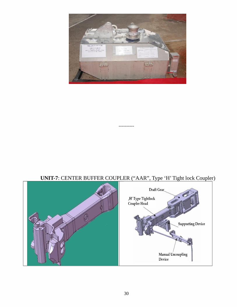
UNIT-7: CENTER BUFFER COUPLER (“AAR”, Type ‘H’ Tight lock Coupler)
30

The coupler provides a means of mechanically connecting individual adjacent vehicles tomake a train. The coupler is located at both ends of each vehicle. When connected to acoupler of an adjacent vehicle, it allows the vehicles to move independently to accommodatetrack curvature and elevation change while remaining connected together.
Couplers are AAR-H type and have anti-climbing features because of vertical interlocking.
Couplers have adequate strength for: Satisfactory hauling of a train of 26 coaches at 110 kmph.
Satisfactory hauling of a train of 18 coaches at 160 kmph
The coupler is opened manually using the coupler operating rod and is closed automaticallywhen the couplers on adjacent vehicles are mated. The coupler automatically locks when fullymated.
LHB coaches have been provided with tight lock centre buffer couplers instead of screwcoupling.
Coupling is possible under angular misalignment both horizontally and vertically. The couplerpermits coupled trains to negotiate vertical and horizontal curves and allows rotationalmovements. The draw gear ensures cushioning effective in both buff and draft.
COUPLER BODY PARTS
31
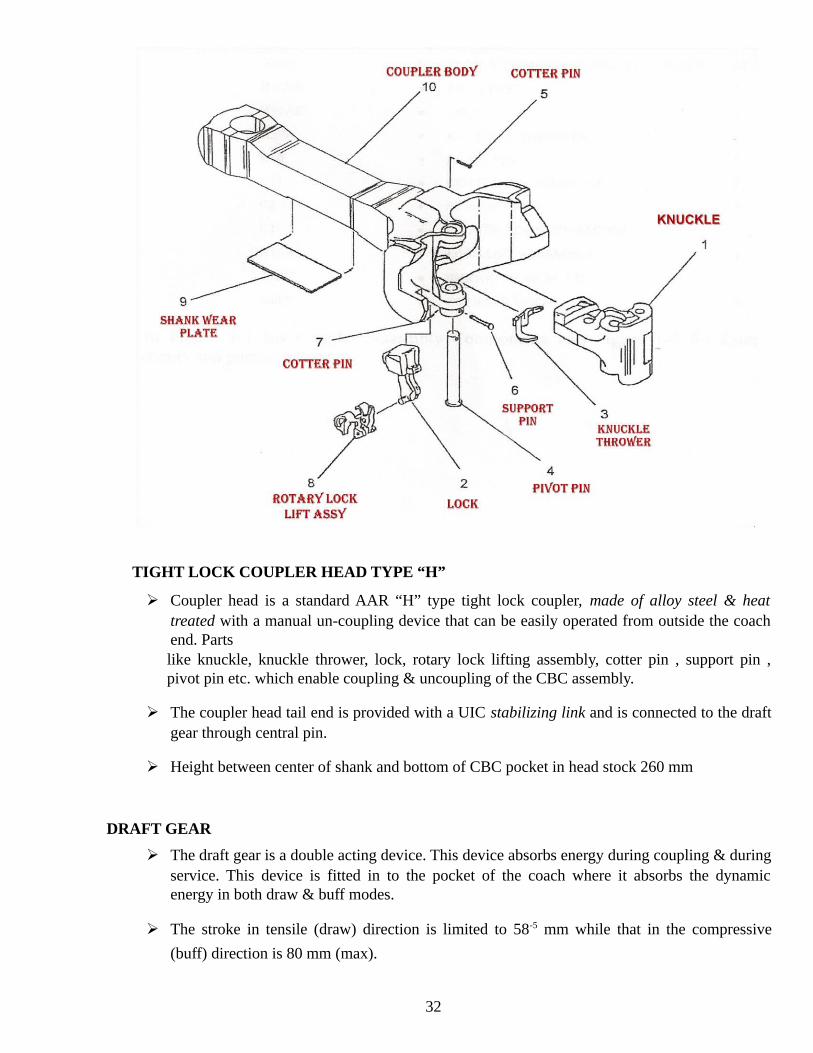
TIGHT LOCK COUPLER HEAD TYPE “H”
Coupler head is a standard AAR “H” type tight lock coupler, made of alloy steel & heattreated with a manual un-coupling device that can be easily operated from outside the coachend. Parts like knuckle, knuckle thrower, lock, rotary lock lifting assembly, cotter pin , support pin ,pivot pin etc. which enable coupling & uncoupling of the CBC assembly.
The coupler head tail end is provided with a UIC stabilizing link and is connected to the draftgear through central pin.
Height between center of shank and bottom of CBC pocket in head stock 260 mm
DRAFT GEAR
The draft gear is a double acting device. This device absorbs energy during coupling & duringservice. This device is fitted in to the pocket of the coach where it absorbs the dynamicenergy in both draw & buff modes.
The stroke in tensile (draw) direction is limited to 58-5 mm while that in the compressive
(buff) direction is 80 mm (max).
32

SUPPORTING DEVICE
The supporting device comprises of four preloaded compression springs. This device is fittedbelow the draw bar in the coach pocket & is bolted on to the body of the coach. The couplerhead rests on the top wear plate of the supporting device. The complete weight of the coupleris taken by this supporting device.
Height of supporting device including wear plate = 187.5 mm
33

34
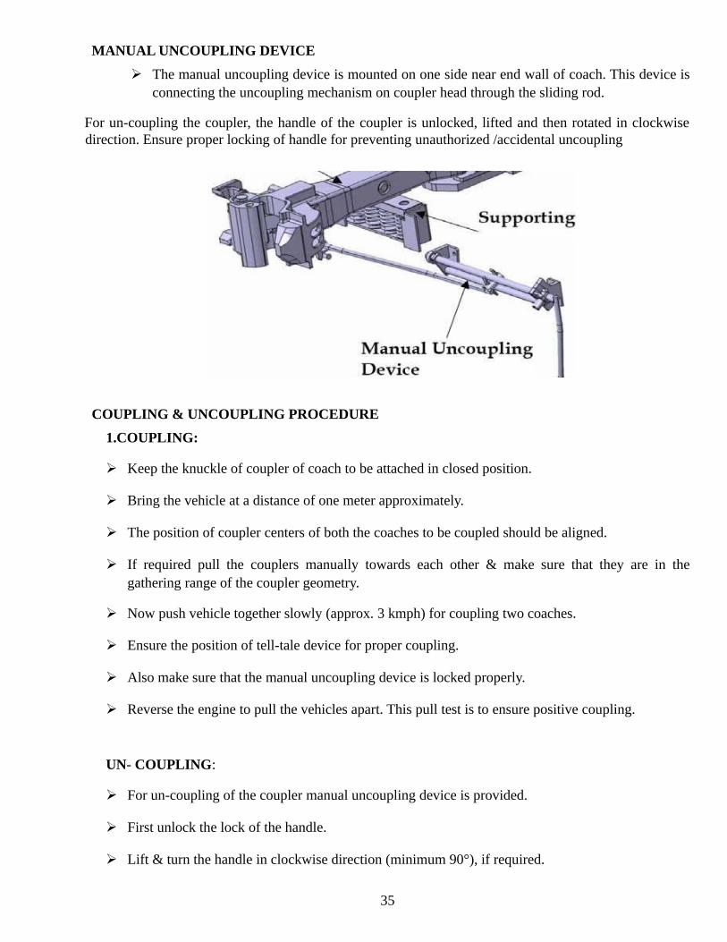
MANUAL UNCOUPLING DEVICE
The manual uncoupling device is mounted on one side near end wall of coach. This device isconnecting the uncoupling mechanism on coupler head through the sliding rod.
For un-coupling the coupler, the handle of the coupler is unlocked, lifted and then rotated in clockwisedirection. Ensure proper locking of handle for preventing unauthorized /accidental uncoupling
COUPLING & UNCOUPLING PROCEDURE
1.COUPLING:
Keep the knuckle of coupler of coach to be attached in closed position.
Bring the vehicle at a distance of one meter approximately.
The position of coupler centers of both the coaches to be coupled should be aligned.
If required pull the couplers manually towards each other & make sure that they are in thegathering range of the coupler geometry.
Now push vehicle together slowly (approx. 3 kmph) for coupling two coaches.
Ensure the position of tell-tale device for proper coupling.
Also make sure that the manual uncoupling device is locked properly.
Reverse the engine to pull the vehicles apart. This pull test is to ensure positive coupling.
UN- COUPLING:
For un-coupling of the coupler manual uncoupling device is provided.
First unlock the lock of the handle.
Lift & turn the handle in clockwise direction (minimum 90°), if required.
35
Then pull the vehicles apart.
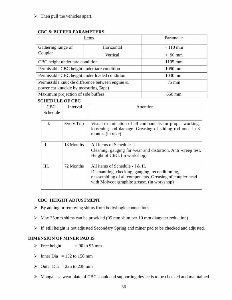
CBC & BUFFER PARAMETERS Items Parameter
Gathering range of Coupler
Horizontal + 110 mm
Vertical + 90 mm
CBC height under tare condition 1105 mm
Permissible CBC height under tare condition 1090 mm
Permissible CBC height under loaded condition 1030 mm
Permissible knuckle difference between engine & power car knuckle by measuring Tape)
75 mm
Maximum projection of side buffers 650 mm
SCHEDULE OF CBC CBC
Schedule Interval Attention
I. Every Trip Visual examination of all components for proper working,loosening and damage. Greasing of sliding rod once in 3months (in rake)
II. 18 Months All items of Schedule- I Cleaning, gauging for wear and distortion. Anti -creep test.Height of CBC. (in workshop)
III. 72 Months All items of Schedule - I & II. Dismantling, checking, gauging, reconditioning, reassembling of all components. Greasing of coupler head with Molycot /graphite grease. (in workshop)
CBC HEIGHT ADJUSTMENT
By adding or removing shims from body/bogie connections
Max 35 mm shims can be provided (05 mm shim per 10 mm diameter reduction)
If still height is not adjusted Secondary Spring and miner pad to be checked and adjusted.
DIMENSION OF MINER PAD IS
Free height = 90 to 95 mm
Inner Dia = 152 to 158 mm
Outer Dia = 225 to 238 mm
Manganese wear plate of CBC shank and supporting device is to be checked and maintained.
36

Shims will not be added/removed in Primary and Secondary Suspension for wheel wearcompensation or buffer height adjustment.
PROFILE GAUGE
JAW GAP GAUGE
37

ANTI-CREEP CHECK
MAINTENANCE OF COUPLER HEAD Monthly Check tell tale of couplers.
Visual check for external damage, condition of wear plate on shank. Replace wearplate if necessary.
Quarterly Repeat above checks. Coat bare steel areas of coupler head body and knuckle with Molycot D321R (orequivalent) dry spray. CAUTION: Do not spray on the knuckle locking surface and internal parts like locketc.
Annually Repeat above checks. Check gap between coupler head and knuckle with Jaw gap gauge (NO-GO). Ifwear out is not acceptable replace knuckle etc., as advised in the maintenancemanual. Check by profile gauge (GO). Conduct anti-creep check.
6 – 8 years
Repeat above checks. Overhaul coupler head. Check parts for wear out. Replace if necessary.
38

MAINTENANCE OF SUPPORTING DEVICE
Monthly
Visual check for external damage. Check height 187.5 mm both sides near the bolts. Tighten the M16 nut to set specified height. Apply grease on wear plate. Check condition of wear plate. Replace wear plate if necessary.
Quarterly Repeat above checks.
Annually Repeat above checks.
6 – 8years
Repeat above checks.
Check compression spring for loss of pre-load. Replace if necessary.
MAINTENANCE OF MANUAL UNCOUPLING DEVICE
Monthly Visual check for external damage, loose bolts etc. Apply grease on the slide and slide rods.
Quarterly Repeat above checks.
Annually Repeat above checks.
Check wear on slide, slide rods and bearings. Replace if wear is excessive.
6 – 8years
Repeat above checks.
----------------
39
UNIT-8: REVISED MAINT. PATTERN OF COACHING TRAINS POLICY CIRCULAR NO-4
Rpc-4 it is maintenance pattern which is based on round trip kms. It has been introduced in Indian railway in October 2001 for 2500 round trip kms with some conditions, and amended in Jan 2007 for3500 round trip kms with some more conditions. These conditions are related with maintenance, infrastructure, time, safety, manpower and of supervision, this pattern of examination is not applicable for meter gauge.
Following approved condition should be fulfilled prior to introduction of rpc-4 in a coaching depot,
PRIMARY END:-the attentions during primary maintenance should be made more intensive withspecial emphasis on the following aspects.
1 The brake block should be changed in bogie sets The brake gearing should be properly adjusted including the slack adjuster A dimensions and
e dimensions & the brake cylinder stroke to ensure 100% brake power Dashpot oil level must be ckd and maintained All missing passenger amenity fittings must be replaced and rake must be turned out as Zero
missing fittings rake. Intensive cleaning of coach toilets No coach should run overdue schedule
2 Clear maintenance time of 6 hours on the pit as per train schedule. Any exception to be jointlydecided by COM/CME of the railways.
3 Provisions of proper washing cum maintenance pit line facility with adequate testingequipment and high pressure water cleaning arrangements
.4 Adequate gang strength with proper supervision. 5 Whenever the lie over is more than two hrs at the platform or rake is stabled in yard the rake
should be locked and +ve security should be provided. 6 Amenity &cleaning attention is carried out at washing line as for as possible, if not feasible
they can be returned from platform yards, the minimum infrastructure on that platform should be as under---
One storages room for essential safety and passenger amenity item. Road transportation facility for ferrying material from the main depot to platform. Adequate numbers of mobile high pressure water pipe line running around the platform/yard
line Washable apron on the plate form lines with covered drains to facilitate movement of
maintenance staff Walkie-talkie/ mobile telephones for quick and easy communications Standard watering
hydrants Flood light at the platform ends for rolling –in – examinations at night and 110 volt.
Inspection lights along the side of the track for night examination of the under gear. the decision regarding whether such trains may be shunted for working on pit line or may be
attended at platform has to be taken after weighing these factors by mechanical and traffic HODS
40

RPC-4 status of implementation should be reviewed every year in the month of June bymechanical and operating branches at divisional level. In January 2007 the round trip kilo meter of RPC4 have been enhanced with following moreconditions:
CME of the railway on which base depot of the rake is located will personally satisfy thatmandatory condition applicable to primary end is fully satisfied. CME of the railway which the base depot of the rake is located shall not permit 3500km roundtrip operation without first obtaining a certificate from the CME of the railway where terminalattention is proposed in place of pit examination.
Functions assigned to CME’s in 1 and 2 above shall not be dedicated S. No.
Category of train Preventive maintenan ce schedule
Under gear examination and brake system maintenance at pit line
Internal cleaning, passenger amenity and watering
Externalcleaningonnominated linewithproper facilities
Enroute/ Terminating examination
Brake system check prior to start at platform atthe other end
1 Mail/Exp one-way run> 3500kms
Primaryend
Both End Both end Both end At every 250to 350km andat terminating
point
Fresh BPC issue
2 Mail/Exp one-way run< 3500kms but round trip
3a Mail/Exp round trip run upto 3500kms
Primary end Both end Primary end Only continuity check if stable in yard otherwise brake power checkwith endorsement on original BPC
3b Shuttles interconnected mail/express round trip run upto 3500kms
At primary end after 3500km or 96hrs. whicheveris earlier
At primary end or as perCME instructions
At primary end once a day
4 Passenger trainswith toilet
At primary end after 3500km or4 days whichever is earlier
As per CMEinstructions
Primary end
5 Passenger trains without toilet
At primary end after 3500km or7 days whichever is earlier
Once a day Primary end Once a day
-------
41

UNIT-:9 FREIGHT STOCK
The term freight stock means all rolling stock other than coaching stock and locomotives irrespective ofcontents and whether attached to a passenger or goods train. The term wagon is applicable only to freightstock. Indian railways have different types of wagons to transport different commodities like coal,cement, fertilizers, ores, food grains, petroleum products, iron and steel and other finished products. Tocater for the transportation requirements various types of freight stocks having different features in useare classified as under.
According to it’s Under Gear Four Wheeled wagon Bogie stock wagon
According to Its Utility
Open wagon Covered Wagon Flat Wagon Hopper Wagon Well Wagon Container Wagon Tank Wagon Explosive Wagon Brake Van
INTRODUCTION :The Cast Steel CASNUB Bogies comprise of two cast side frames and a floating bolster. Thebolster is supported on the side-frames through two groups of spring, which also incorporate theload proportional friction damping. The side-frames are connected by a fabricated mild steelspring plank to maintain the bogie square. The various bogie versions developed are as under:-
CASNUB-22W CASNUB-22W (Retrofitted) CASNUB-22W (M) CASNUB-22NL CASNUB-22NL M CASNUB-22NLB CASNUB-22HS CASNUB-22NLC
SALIENT FEATURES: The salient features of the bogie are :
42

Sl. No.
ITEMS DESCRIPTION
1 Gauge 1676 mm
2 Axle load 22.9 T to all except, CASNUB –NLC up to 25 t axle load with K type CTRB
3 Wheel diameter 1000 mm new, 956 mm new for 22W (retrofitted) 906 mm condemnation
4 Wheel base 2000 mm
5 Type of roller bearing Slandered AAR cartridge bearing
6 journal centers 2260 mm
7 Distance between side bearer
1474 mm
8 Type of side bearer *) Roller type clearance for CASNUB 22 W. a) Spring loaded constant contact for LCCF-20(c). b) Constant Contact type (metal bonded rubber pads for
others. c) P U pad for CASNUB 22HS
9 Anti rotation feature Anti rotation lugs have been provided between bogie bolster and side frame.
10 Type of brake beam Unit type cast steel brake beam slide in pocket in all bogies except hanger type brake beam suspended from side frames bracket in CASNUB 22 W (M)
11 Center pivot 1) IRS spherical type for 22W only. 2) Spherical type for others. 3) Flat type in BLC wagons
12 Suspension details 4) Long travel Helical Springs.
13 Elastomeric Pad Elastomeric Pad has been provided between adopters and sideframes pedestal roof to reduce wheel flange wear.
Nominal Clearance: The nominal clearance are as under:-
43

BOGIE COMPONENTS: The Casnub bogie assembly consists of the followingcomponents:-
Wheel set with CTRB bearing. Axle box/adapter, & side frame key assembly and retainer bolt in wide jaw
adaptor. Side frame with friction wear plates.
Bolster with wear liners.
Spring plank, fit bolts & rivets.
Load bearing springs and snubber springs.
Friction shoe wedge.
Centre Pivot arrangement comprising of centre pivot top, centre pivot bottom, centre pivot pin, centre pivot retainer & locking arrangement in all bogie except 22WR .
Side bearers/PU pad.
Elastomeric pads.
Bogie brake gear.
Brake beam.
The springs are condemned on the basis of free height. Springs should replace if minimum spring heightis at or less than shown below:
44
S.N. Description Type of Casnub Bogies
22W,22W(R) 22W(M) 22NL,NLB 22HS
1. Lateral clearance between sideframe bolster
18mm 18mm 18mm 25mm
2. Lateral clearance between sideframe and axle box/adapter
25mm 25mm 16mm 16mm
3. Longitudinal clearancebetween side freame & axlebox/adapter
2mm 10mm 9mm 9mm
4. Longitudinal clearancebetween side freame andbolster
6mm 6mm 6mm 6mm
5. Clearance between anti-rotation lug & bolster.
4mm 4mm 4mm 4mm
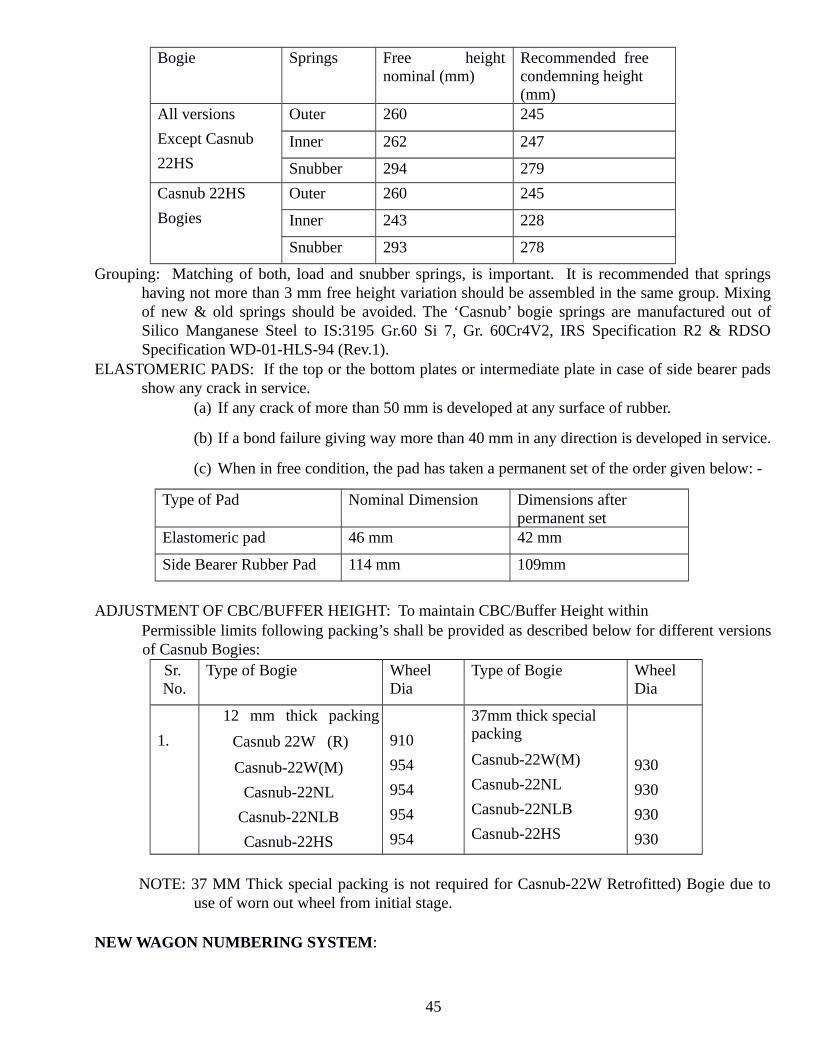
Bogie Springs Free height nominal (mm)
Recommended free condemning height (mm)
All versions
Except Casnub
22HS
Outer 260 245
Inner 262 247
Snubber 294 279
Casnub 22HS
Bogies
Outer 260 245
Inner 243 228
Snubber 293 278
Grouping: Matching of both, load and snubber springs, is important. It is recommended that springshaving not more than 3 mm free height variation should be assembled in the same group. Mixingof new & old springs should be avoided. The ‘Casnub’ bogie springs are manufactured out ofSilico Manganese Steel to IS:3195 Gr.60 Si 7, Gr. 60Cr4V2, IRS Specification R2 & RDSOSpecification WD-01-HLS-94 (Rev.1).
ELASTOMERIC PADS: If the top or the bottom plates or intermediate plate in case of side bearer padsshow any crack in service.
(a) If any crack of more than 50 mm is developed at any surface of rubber.
(b) If a bond failure giving way more than 40 mm in any direction is developed in service.
(c) When in free condition, the pad has taken a permanent set of the order given below: -
Type of Pad Nominal Dimension Dimensions after permanent set
Elastomeric pad 46 mm 42 mm
Side Bearer Rubber Pad 114 mm 109mm
ADJUSTMENT OF CBC/BUFFER HEIGHT: To maintain CBC/Buffer Height within Permissible limits following packing’s shall be provided as described below for different versionsof Casnub Bogies:
Sr. No.
Type of Bogie Wheel Dia
Type of Bogie Wheel Dia
1.
12 mm thick packing
Casnub 22W (R)
Casnub-22W(M)
Casnub-22NL
Casnub-22NLB
Casnub-22HS
910
954
954
954
954
37mm thick special packing
Casnub-22W(M)
Casnub-22NL
Casnub-22NLB
Casnub-22HS
930
930
930
930
NOTE: 37 MM Thick special packing is not required for Casnub-22W Retrofitted) Bogie due touse of worn out wheel from initial stage.
NEW WAGON NUMBERING SYSTEM:
45

The new wagon numbering system is being done as per railway board’s instruction issued vide lettervide letter Number. 2000/M (N)/60/2/wagon census dated 4th July 2003. The wagon number shallconsist of 11 digits. First two digits will indicate types of wagon, next two digits will indicate owningrailway, next two digits will indicate year of manufacture, and next four digits will indicate individualwagon number and the last digit will be a check digit. Brief is as under:
C1 C2 C3 C4 C5 C6 C7 C8 C9 C10 C11 Type of stock Owning Rly Yr. of Mfg. Ind. Wagon no. Check digit
Procedure of Check digit is calculated as under: Step-1. Add all the character in the even number (S1)= C2+C4+C6+C8+C10
Step-2. Multiply S1 by 3 = 3 S1
Step-3. Add all the character in the odd number (S2)= C1+C3+C5+C7+C9 (Except check digit)
Step-4. Add 3S1 + S2 = S4
Step-5. Round this total up to next multiple of 10.
Now Check digit is the number required to be added to roundup to the next multiple of 10. If the totalin S4 is already a multiple of 10, then the check digit will be Zero.
-------
UNIT-10: BOGIE MOUNTED BRAKE SYSTEM FOR FREIGHT STOCK
INTRODUCTIONIn the air brake system, a lot of developments have taken place such as bogie mounted Air brakesystem, Twin pipe air brake system, Automatic load sensing device etc,.
46

Recently, Bogie mounted Brake System (BMBS) has been introduced for freight stock. The detailsand maintenance of BMBS are given in this handbook.
DESCRIPTION OF BMBSThe Bogie Mounted Brake system (BMBS) equipment consists of a transversely mountedpneumatic Brake Cylinder with a self-contained, double acting slack adjuster, two brake beams,and two bell crank levers and interconnecting push rods. The hand brake arrangement is availableas a mechanical model with two flexible handbrake cables. The pneumatic Brake Cylinder is 10" indiameter for application with high friction brake shoe (K type) on casnub type bogies. The systemconsists of a unique design with two pneumatic Brake Cylinder (one per bogie) to deliver reliablebraking performance and is light in weight. It fits into CASNUB bogie and uses 58 mm thick brakeshoes.
Brake cylinder contains an integral double acting slack adjuster, which provides optimal brakingforce and minimizes shoe & wheel wear. The design is with high strength and minimal brake beamdeflection.
FIGURE -1
WORKING DESCRIPTION OF BMBSDuring application, the air is introduced into the brake cylinder, which forces out the piston alongthe ram assembly. The brake cylinder is floating in nature, as result the brake cylinder extendsequally on both the sides. This extension of brake cylinder causes the rotation of the bell cranklevers on their pivot (which is on primary brake beam) and forces the push rod to move towards thesecondary beam. This movement causes the secondary brake beam to move towards the wheels andapply force on the wheels. Simultaneously a reaction force is developed which causes the primarybrake beam (along with levers and brake cylinder) to move towards the wheels. The primary brakebeam continues to move until it touches the wheels and apply force on the wheels.
47

48

When the brakes are released, the air from the brake cylinder is exhausted to the atmospherethrough the Distributor valve. The return spring inside the brake cylinder pushes the piston alongwith the ram assembly back to its original position. The bell crank levers rotate back, causing thebeams to move back to their earlier positions. The brake cylinder is equipped with a double actingslack adjuster. If there is any wear (Brake Shoe/Wheel) or any slackness in the structure, it will beautomatically compensated by the built in slack adjuster which pays out to fill the gap.
SALIENT FEATURESMore Safety
Two nos. of 10" brake cylinders with inbuilt double acting slack adjuster have been used per wagon.Along with this an automatic load-sensing device has been used for two stage braking (empty /loaded). This delivers optimum braking performance and hence increases safety parameters. Reliability Instead of one 14” cylinder, two 10” cylinders have been provided per wagon (one per bogie)., Thisincreases the system reliability as in case of failure of one cylinder the wagon can be moved onanother cylinder with the isolation of failed cylinder.
Advantages of BMBS:- 1Low Maintenance cost 2 Low Fitment cost 3 Low Pay load cost 4 Easy Retro fitment 5 Simplified Hand Braking Installation 6 Replaceable Brake Heads 7 Integral Double Acting Slack Adjuster 8 Patented Beam Design 9 Under Bolster Design
BMBS is reduces bending loads in the beams, enabling the use of lighter structure with no sacrifice in the performance. The brake cylinder is mounted parallel to the brake beams and transfers forces through the bell cranks. This parallelogram design improves the efficiency and aligns the braking forces with the wheels, which reduces the shoe and wheel wear.
The system delivers optimum braking performance while minimizing weight.
The system can be easily fitted on any IR standard casnub bogie without making any modifications. This is a drop in fit system and does not require any special tools and training for installation/assembly.
To achieve uniform wheel loading, the loads are applied to the ends of the brake beam instead of center.
The system uses IR standard 58 mm thick K type brake blocks.
A replaceable brake head design permits the reuse of the beam in the event that the brake heads gets damaged. Replacement of the brake head is quickly accomplished by removal of only one pin.
49
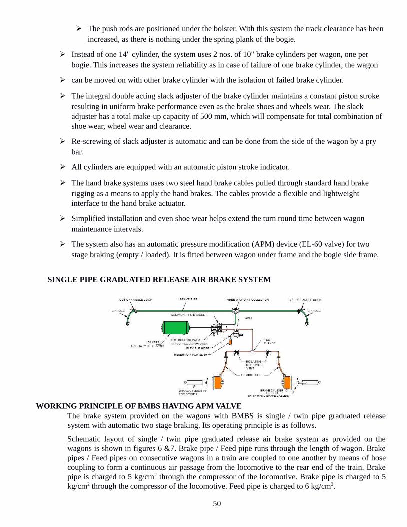
The push rods are positioned under the bolster. With this system the track clearance has been increased, as there is nothing under the spring plank of the bogie.
Instead of one 14" cylinder, the system uses 2 nos. of 10" brake cylinders per wagon, one per bogie. This increases the system reliability as in case of failure of one brake cylinder, the wagon
can be moved on with other brake cylinder with the isolation of failed brake cylinder.
The integral double acting slack adjuster of the brake cylinder maintains a constant piston stroke resulting in uniform brake performance even as the brake shoes and wheels wear. The slack adjuster has a total make-up capacity of 500 mm, which will compensate for total combination of shoe wear, wheel wear and clearance.
Re-screwing of slack adjuster is automatic and can be done from the side of the wagon by a pry bar.
All cylinders are equipped with an automatic piston stroke indicator.
The hand brake systems uses two steel hand brake cables pulled through standard hand brake rigging as a means to apply the hand brakes. The cables provide a flexible and lightweight interface to the hand brake actuator.
Simplified installation and even shoe wear helps extend the turn round time between wagon maintenance intervals.
The system also has an automatic pressure modification (APM) device (EL-60 valve) for two stage braking (empty / loaded). It is fitted between wagon under frame and the bogie side frame.
SINGLE PIPE GRADUATED RELEASE AIR BRAKE SYSTEM
WORKING PRINCIPLE OF BMBS HAVING APM VALVEThe brake system provided on the wagons with BMBS is single / twin pipe graduated releasesystem with automatic two stage braking. Its operating principle is as follows.
Schematic layout of single / twin pipe graduated release air brake system as provided on thewagons is shown in figures 6 &7. Brake pipe / Feed pipe runs through the length of wagon. Brakepipes / Feed pipes on consecutive wagons in a train are coupled to one another by means of hosecoupling to form a continuous air passage from the locomotive to the rear end of the train. Brakepipe is charged to 5 kg/cm2 through the compressor of the locomotive. Brake pipe is charged to 5kg/cm2 through the compressor of the locomotive. Feed pipe is charged to 6 kg/cm2.
50

The wagons are, provided with automatic pressure modification (APM) device EL-60 valve to caterfor higher brake power in loaded condition instead of the conventional manual empty load device.With the provision of this, brake cylinder pressure of 2.2 ± 0.25 kg/cm2 is obtained in emptycondition and 3.8 ± 0.1 kg/cm2 is obtained in the loaded condition. To obtain this a change over mechanism, APM under-frame and side frame of the bogie. Themechanism gets actuated at a pre-determined change over weight of the wagon and changes thepressure going to the brake cylinder from 2.2 ± 0.25 kg/cm2 to 3.8 ± 0.1 kg/cm2 in case ofchangeover from empty to loaded and vice versa
BRAKE CYLINDER - 10”DIA.:-
The built-in slack adjuster compensates for the wear of brake blocks during the brake applicationthrough equivalent pay-out. For paying-in, a pry bar is applied between the brake shoe and wheeland the rigging is pushed in. The brake cylinder has got a double acting slack adjuster as a result the actuator of brake cylinderwill continue to move out till all the slack in the system is take care off and reaction force of thewheels is encountered. This ensures that every time every time the brake application takes place,sufficient brake force is delivered on the wheels. The brake cylinder compensates for any change in gap between brake block and wheel through theinbuilt slack adjuster. Therefore it maintains a constant gap between the shoe and wheel and hencea constant piston strike. The slack adjuster works in both the condition whether there is an increaseor decrease in gap. Since the brake cylinder maintains a constant piston stroke, there is no need tomeasure the piston stroke time and again.
There is an indicator on the brake cylinder to show the "APPLIED" or "RELEASED" condition ofthe Brake Cylinder. Don't hit the indicator, it may retract slowly. Hitting can bend / damage theindicator. The brake cylinder has slack adjustment of 500 mm which could compensate of brake block wear of48 mm (From 58 to 10 mm) and wheel wear of 47 mm (i.e., wheel dia reduce from 1000 mm to 906mm). The brake cylinders used on the bogie mounted brake system are of two types; with hand brakecables and without hand brake cables. The brake cylinder with hand brake cables are used forinterface with the hand brake arrangement on the wagons.
APM Device (El-50 valve)
APM device is interposed between bogie side frame of casnub bogie and the under frame of thewagon. It is fitted for achieving 2-stage load braking with automatic changeover of brake power.Only one APM is required per wagon. It restricts the brake cylinder pressure coming from theDistributor valve to 2.2 ± 0.25 kg/cm2 in empty condition of the wagon and allows the brakecylinder pressure of 3.8 ± 0.1 kg/cm2 in loaded condition of the wagon. The sensor arm of the APMdevice comes down for sensing only during the brake application.
51

The complete movement of the sensor point is 104 mm. The first 80 mm of the sensor pointis for the loaded zone and the balance is for the empty zone. The deflection of the bogie from tareto changeover weight is added to 80 mm to arrive at the total movement of the sensor point to beadjusted on the wagon. The gap between the sensor point and the bogie is to be measured at thepoint it touches the top surface of the side frame. Also ensure that the sensor point touches in themiddle of the side frame.
It has an indicator to show the empty or loaded position. Whenever the indication is "ON"i.e., it is showing the orange colour, it is indicating the empty condition with brake cylinderpressure of 2.2 ± 0.25 kg/cm2. When there is no indication in the indicator, it is loaded conditionwith 3.8 ± 0.1kg/cm2 going to the brake cylinder. It has a quick connect socket to connect the gaugeto the check the pressure through the pressure gauge.
--------
52

UNIT-12: BLC WAGON
DESIGN FEATURES OF LOW PLATFORM CONTAINER FLAT
The design of flat car for carriage of ISO Containers has been developed carefully since thecontainers are geometrically awkward loads and maximum speed of the linear trains is an importantfactor unlike the normal freight trains. It is important that the size of container. It is seen that height andlength of the containers have been continuously increasing in the last two decades and are likely toincrease further. Therefore, the flat car design should cater for such changes. At present container flatstype BFKI are being used for the Inland Movement of ISO containers on B.G system of Indian Railwaysone of the difficulties with the movement of series ISO containers of 8' 6" height is that it infringes thestandard moving dimensions on the B.G system. However, special dispensation has been obtain topermit unrestricted movement of these containers. Meanwhile International Organization for thestandardization (ISO) adopted 9'6" height containers for International movements. A detailed study ofthe implication of carrying these size containers reveal that:-
It infringes the max moving dimensions of standard 'X' class engine by 254 mm vertically 533horizontally. It is not permitted to run at speeds more than 75 kmph. It will be treated as on OverDimensional Consignment (ODC).In addition to above shortcomings this flat is not of optimum designand not energy efficient and has been payload to tare ration of 2.24.It was therefore considerednecessary to design of low platform container flat to remove the disability caused by classification ofsuch wagons as ODC. The low platform container flat being manufactured by M/S. HindustanDevelopment Corporation of India Ltd. 'CONCOR' has following salient features:
Minimum platform height of 1009 mm for carriage of maximum height/ISO container of 2896 mm.
Pay load to tare ratio of 3.37.
A new hybrid design of bogie frame and bolster in order to bring down the platform height of container flat.
Use of 840 mm dia wheel to achieve low platform height.
Use of new concept of bogie suspension design to achive 100 kmph operational speed.
Use of spring loaded side bearers sharing 90% of the load under air condition to avoid things.
Use of air brake system.
Use of multiple car units each having 'A' and 'B' cars with AAR 'E' type center buffer coupler o raisedends of 'A' cars and use of slack less draw bar system on the inner ends of 'A' cars and on all 'B' cars.
Use of modular design of 5 cars unit will also ensure flexibility of operation and result in substantial saving in energy with improved pay load to tare ratio.
SPECIAL FEATURES OF BLC WAGONS:- These wagons are designed to carry ISO containers with a height of 2896 mm as Non-ODC load.
53
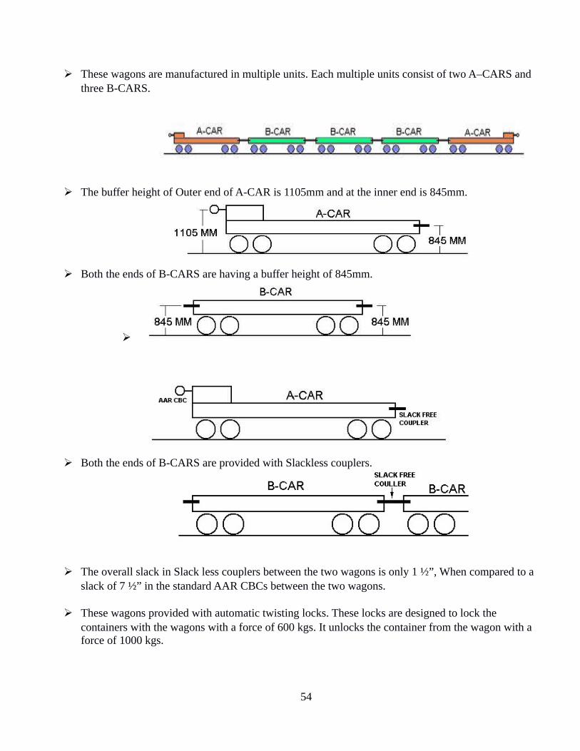
These wagons are manufactured in multiple units. Each multiple units consist of two A–CARS and three B-CARS.
The buffer height of Outer end of A-CAR is 1105mm and at the inner end is 845mm.
Both the ends of B-CARS are having a buffer height of 845mm.
Both the ends of B-CARS are provided with Slackless couplers.
The overall slack in Slack less couplers between the two wagons is only 1 ½”, When compared to a slack of 7 ½” in the standard AAR CBCs between the two wagons.
These wagons provided with automatic twisting locks. These locks are designed to lock the containers with the wagons with a force of 600 kgs. It unlocks the container from the wagon with a force of 1000 kgs.
54

A formation can be formed with 9 multiple units with 45 wagons. The length of each unit is 69 meters approximately.
12.3 UNDERFRAME DESIGN: The underframe is a light weight all welded skeletal design for an optimum tare to pay load ratio. In order to reduce the tare weight and optimize the design of container copper bearing high tensile steel to IS:8500 Fe570B is used. COUPLER :If single car unit of low platform container flats have to be built the two ends ofunderframe will have to be raised for accommodating the coupler with specified coupling height of1105 mm. The space required to accommodate the couplers of 1105 mm will thus be not available foraccommodating the ISO containers. Consequently the length of the wagon will increase by 3000mm.This will turn reduce the no. of wagons on a loop line from 42 for existing BFKI flats of 38 resultingin loss of capacity. Due to extra length tare weight of the wagon also will increase considerablywhich will turn result in extra energy consumption. Further use of individual wagons having theirtwo ends raised is technically not desirable, because of the eccentricity between the draft line and thecentre of the underframe momentary of loading of certain wheels would take place, when the tractiveeffort is applied suddenly by the locomotive and this would happen on all the wagons. In order toovercome these draw backs, concept of multiple car units using standards CBC at a height of1105mm at the two ends of each unit to facilate coupling with the locomotive and slack free draw barsystem at lower level in between intermediate cars was the only acceptable solution.
The basic object of using this system is to reduce the amount of slack within the train as compared tonormal CBC coupling mechanism. The reduction of this free slack provides many benefits over aconventional coupling.
Reduction of accelerations, decelerations and impact loading that act upon the loading. This helps to minimize lading damage.
Reduction of impact forces that act upon the 3 car structure as a result of this free slacks.
Reduced car maintenance cost as result of induced impact loading on the car structure and components.
Greatly increased riding quality, lesser damages to the track.
Elimination of free slack reduces abuse on the car structure.
Slack free draw bar system comprises of key stone. Mini gear, Mc Conway & trolley drawer, Standard AAR Yoke and indigenously developed striker casting.
55

BOGIE DESIGN: Cast steel bogie design for low platform container flats, is basically a threepiece planked bogie with secondary coil spring suspension and load proportional friction damping and AAR Cartridge bearing.
I. BOGIE FRAME DESIGN: Adoption of 840 mm dia wheel became necessary to bring down the height of Container flat
as far as possible. This has brought down the height of the platform by 80mm in comparison to thewheel diameter of 1000mm provided on the existing BFKI Container flats. Critical problems such asminimum clearance between the bottom most point of the bogie and rail level permitted under worstcondition i.e. 102mm, and height of the bolster ect, have been taken care of. A design of bogie framewith 2000 wheel base and completely new design of bolster is used. All these exercises have resultedin reduction in the height of the centre pivot from the rail level from 932mm on the existing BFKIcontainer flats to 729mm on the low platform container flat, thus saving 203 mm in the verticaldirection. The design thus ensures a vertical clearance of 17mm with the maximum movingdimensions of standard ‘X’ class locomotive when 9’6’’ (2896mm) and height 8’00’ (2438mm) wideISO container are loaded.
II.SUSPENSION DESIGN: New concept of suspension design softer under tare and suffer under gross loaded condition has been adopted. The two stages vertical suspension was necessary to provide higher static deflection in empty condition, so that spring off-loading in the empty condition lies within limits. Vertical suspension in loaded condition is stiffer on account of the constrain of limit of buffer height variation. Keeping in mind the space available for accommodating the springs, the design in such that the stress level in the spring in the dynamic condition is within limits, beside sufficient residual deflection. In addition, load proportional friction damping arrangement with sufficient damping force is provided. To achieve this snubber springs are made stiffer but at the same time the stress level under dynamic load are not high and also sufficient residual deflection is available. Which gives better fatigue life of the spring. As result vertical damping factor is increased to 0.25 as compared to that of BFKI Container wagon which is 0.15. This optimization of suspension design lead to higher safety margin against derailment.
III. ELASTOMERIC PADS: Elastomeric pads basically provide flexibility in lateral mode at the axel box level and
this reduces wheel wear tendency.
A stiffer elastomeric pad reduces the uncontrolled lateral vibration at primary levelwhich eliminates the hunting tendency.
Elastomeric pads are made stiffer without increasing the hardness of rubber so that thefatigue life do not deteriorate.
The extent of stiffening is kept as low as possible so that wheel wear is not affected asmuch,
The longitudinal clearance between elastomeric pads and axle box crown is eliminatedfor effective functioning of the pads.
56

IV) LOAD DISTRIBUTION: The weight distribution between centre pivot and side bearer has been optimized to avoid hunting 90% of the load under tare condition is borne of the two side bearer of spring loaded design. The spring loaded side bearer arrangement (refer figure 2) is having a distinct advantage of retaining the load distribution between centre pivot and the sidebearer irrespective of manufacturing inaccurate as well as condition of the wagons (new or old) only 10% of the tare weight will be borne of the centre pivot which will also transfer the full pay load under taken condition.
AUTOMATIC TWIST LOCK
In order to minimize the manual operation automatic twist locks of M/s Holland and co. USA isfitted on low platform container flat for securing the containers. (Unique feature of this lock is itslocking and unlocking is automatic). Radii of spindle head are so designed that while loweringthe container, lock automatically operates the moment of force of 600 kg is exerted by thecontainer. For fitting the container from the container flat a force of 1000 kg is required for thelock to operate.
12.8 COMPARTIVE FEATURES OF BLC-BFKI
S.NO FEATURES BLC BFKI 01 Wagon Unit Consist of 5 wagon 2 Nos.
A-CAR+3Nos. B-CAR Single Wagon
02 Platform Height from RL
1009mm 1269 Wagon
03 Unit of Wagon Length over Head Stock
A-CAR 13625 mm B-CAR 12212mm
13716mm
04 Tare A-CAR 19.1t B-CAR 18.1t
20.5t
05 Pay Load 61.t 48.t 06 Wheel dia 840/780mm 1000/906mm 07 Type of bearing Tapered two row Cartridge
bearing Tapered two row cartridge bearing
08 Speed 100kmph 75kmph 09 Coupling CBC & Slack less Draw
bar CBC
57

10 Twist Lock Automatic Manual 11 Empty/Load Device Two stage automatic
pneumatically operated Manually leverage
12 Side Bearer Arrangement Spring loaded side bearer arrangement
Rubber bonded
13 Suspension Two stage suspension Single suspension
14 Rake carrying capacity/Rake Length
45 Wagons 42 Waggons
15 Brake System Air Brake Vacuum Brake 16 Brake Cylinder Pressure 3.8 Kg/CM Sq. in loaded
2.2 Kg/CM Sq. in empty -------------
SALIENT FEATURES :The salient features of the bogie are: Gauge 1676mm
Axle load 20.3T
Wheel diameter 840mm (new) &780mm(condemning)
Wheel base 2000mm
Type of bearing American association of railroad
Cartridge tapered roller bearing
Jaw (6”*11”) wide jaw
Distance between Journal centres 2260 mm
Distances between Side Bearers 1750mm
Type of side Bearer Spring loaded
Type of pivot Flat
Anti-rotation features Anti-rotation lugs have been provided between bogie Bolster and sideframe.
Type of Brake Beam Unit type fabricated Brake Beam
SPRINGS: The bogie is fitted with two groups of long travel helical springs nests. The spring groups per bogie are as under: 20.3t 14 Outer 12 Inner 4 Snubber
58
DAMPING: The suspension is provided with load proportional frictional damping arrangement with thehelp of a cast steel wedge supported on the snubber springs.
SIDE BEARERS: The bogie is fitted with spring loaded side bearers having 90% of the load under tare condition to avoid hunting.
BRAKE BEAM: The bogie is fitted with unit type brake beam. The brake heads are integral part of the Brake Beam which slide in the guide cavity of the Side Frame. A spring steel wear liner is provided in this with a centralizing feature.
--------
UNIT -12 Clean Train Station
During October 2002, Railway Board decided to launch “Clean Train Station” as a majorinitiative for improving train cleanliness involving the reputed and professional agencies inthis field. Under the enroute scheme, the train will be cleaned by mechanized process atmid-stations during its scheduled halt. The interior of coaches will be cleaned, specially toilets,by using sophisticated equipment and machines such as pressurized water jet, scrubber,blotters etc. Least amount of water is utilized with best standards of cleaning. Toilets & sittingareas of coaches are dried after cleaning. Only environment friendly and biodegradablecleaning agents will be used for cleaning and disinfecting the toilets. The toilets and the sitting areas of the coaches will be sprayed with Mosquito Repellent tocontrol mosquito menace. The area between toilets, doorways, vestibule and the aisle shallalso be cleaned. The window glass of AC coaches will also be cleaned at the platform side.This scheme is an attempt to increase the passenger satisfaction to a higher degree. Theaccumulated waste from the coaches will be collected and disposed off to its designated place. The mechanized cleaning operation under this scheme is a self containedoperation and all the resources required, except water for cleaning to make this service have tobe arranged by agency itself.
OBHS (On Board House Service)
The following works are executed under OBHS. This service is given to the passenger enroute.
1. Every cleaning staff should report to the on duty railway supervisors.2. House keeper must maintain a work dairy.3. House keeper must collect the passengers feed back from certified on duty Railway supervisors.
59

4. Must keep a register for cleaning tools and cleaning agents, uniforms for cleaners.5. Each Janitor (cleaning staff) is nominated for 3 numbers of coaches.6. Four numbers of passenger’s feed back form for each coach in one trip (8 numbers for round
trip) must be filled by passengers.7. Executive house keeper must keep a tool kit having screwdriver, hammer, pipe wrench,
adjustable spanner for carpentry and pipe fitting works. 8. Janitors must clean the following areas.
Toilets, doorways, gangways and vestibules from 5.00 hrs to 9.00 hrs and 16.00 hrs to 20.00 hrs.
High pressure jet is used Lavatory outside wash basin and its areas should be cleaned and mopped. Drying the toilets floor surface with mopper, sponge. Spraying disinfectant. Dry cleaning and mopping of passenger compartments. Use of Glue Board to catch rats. HIT or Baygon spray for insects killing. Providing Liquid soap, Toilets paper, Odonil Air freshener, mirror cleaning with micro fiber cloth and Collin.
DRS Card ( Deficiency Rolling Stock ) cards are forms for listing the damages anddeficiencies on Rolling Stock. One copy is made for Guard and the other is retained by TXR.On arrival back of the rake, the TXR and RPF staff will check the train jointly and fittingsmissing in a coach are identified against the fittings which were available before departure.This will help in listing out the deficiencies in a coach on its arrival.
IRCA
Indian Railway Conference Association situated in New Delhi gives out the rules for theStandard and condemning sizes of various components used on a Rolling Stock. It also givesthe guidelines for maintenance of rolling stock in Workshop and in openlines. The rule booksissued for the Carriage and Wagons departments are
Part III For wagon stockPart IV For coaching stockIRCA Part III & IV contain 4 chapters each.Chapter I - DefinitionsChapter II – Workshop repair practiceChapter III – Maintenance practice in open lines Chapter IV – Rejection rules.
Special Repair - :
60

The Special repair ( Non POH repair ) are those repair which can not be done in the sicklines with their existing facilities.
Any coach not capable of being repaired with the existing facilities or whose repairs arein such nature which are prohibited to be done in sickliness, should be sent to the baseWorkshop for repairs. Special repair coaches should be sent to the base Workshop only afterobtaining the permission of the CME and when the shops have programmed them.
In this connection the C &W incharge of the depot should prepare a complete list ofdamages and deficiencies and forwarded it to DME for getting permission of CME to bookthe coach to the shop for Non POH repair. A copy of the list of damages and deficienciesshould simultaneously be sent to the Workshop concerned for planning it in their programme.
61

UNIT-13: FREIGHT TRAIN EXAMINATION
FREIGHT TRAIN EXAMINATION Introduction: The efficient working of freight stock is closely linked to the standard ofyard maintenance. Several factors are responsible for good and quality examination/repairs in the yard. The method of examination is described as under. New Pattern of Freight Train Examination: It is based on the Revised JPO issued by Railway board letter No. 94/M(N)/951/57 Vol-2 dated 25.10.04,letter NO-2005/M(N)/951/13 Dated 07.04.05 and even no dated 25.04.2006 and 5.11.07. Following are the main feature of new pattern examination of freights trains. 1. Word CRT has been deleted as the stock has been phased out. 2. The freight train can only be subjected to examine for intensive End to End, Premium End to End and Close Circuit rakes. 3. The practice of safe to run examination of freight trains per se may be discontinued. 4. En route rolling-in-Examination freight trains may be discontinued. However rolling in examination as part of intensive examination will continue. 5. Post loading examination by TXR Staff may be discontinued for all type of stock (except loading of steel consignment). This check is to be carried out by Guard and Driver as per standard proforma issued by Railway Board. The post loading check must be carried out by TXR Staff and securing of steel bundles with lashing chains may be ensured. 6. After Tippling the rake will be offered for post Tippling examination, in case less than three rakes are day, the check may be carried out by guard and driver as per standard proforma issued by railway board. In cases 3 or more trains are being tippling, post tippling check will be done by Skelton TXR staff. After tippling the rakes should be subjected post tippling check either by TXR Staff or by GUARD &Driver in case of non provision of TXR Staff in siding. 7. It should be ensured that unexamined lead (after unloading before next TXR Point)of freight trains running end to end pattern or invalid BPC in case of premier & ccrakes does not exceed 400 kilometer . 8. Since multiple loading and unloading are permitted in CC & Premium Rakes .movement of CC rakes &premium rakes will be monitored through FOIS by Traffic Department with C & W control. 9. In case of mechanized loading an unloading (i.e. BOXN wagon examination by TXR will be desirable. 10. In case of clearance of stable load instruction contained in Board letter No. 2000/safety (A&R) /19/35/ dated 31.7.01 should be followed. 11. The CC rakes shall be offered for PME in empty condition at the cc base depot where the cc base depot where the cc rake was originally formed. 12. ROH and POH wagons from CC rake will be marked and detach at base Depot.
62

13. The rake integrity of CC rake as listed in the BPC should be maintained .However up to 4 wagon (10 FWU) may be replaced by good examined wagons in the entire Run between the two PME.(05 BLC or one mark in case of BLC rakes allowed for attended or replaced). 181
63

PREMIUM RAKES: This new type of examination for air brake stock (i.e. BOXN, BOXNHS, BCN, BCNHS, and BOBRN etc) introduced in Indian railway w.e.f. April 06 as per instructions issued by railway board. The salient features of such types of examination are under: 1. Premium rake will be form out of air brake stock (i.e. BOXN, BOXNHS, BCN, BCNHS & BOBRN etc.) only. 2. Such rakes will be given intensive examination in empty condition at nominated examination yard only. 3. Premium examination point must be upgraded to “A” category yard on top priority. 4. Stipulation to form rake out of Off POH /ROH wagons as in case of CC rakes are not applied in case of premium rakes. 5. Similar types of wagons are taken to form premium rakes, mixed wagons not allowed for such rake. 6. The rakes will be turned out with minimum 95% brake power and BPC will be issuedon Green Book only. 7. The validity of BPC to be issued for 12 days including date of issue. However grace period of 3 days is given when rake is loaded condition and on 15 days rake must be unloaded and must be offered for C &W examination. 8. The rake is handed over to Operating Department for multiple loading and unloading within 12 days. 9. After each loading and unloading , the rake must be offered for Guard and Driver check before commencement of journey as per proforma issued by Railway Board and observation will be recorded on the relevant column of the BPC. 10. Movement f premium rakes will be monitored through FOIS by Traffic Department with Mechanical Department. 11. If the rakes stabled in yard more than 24 hours, the rakes must be offered for C&W examination otherwise BPC will be treated as invalid. 12. Man hours are decided as 75 for Premium End to End (PEE) examination. 13. The integrity of rake will be maintained. However 4(10 FWS) wagons may be replaced by examined wagons en route.
Advantage of Premium Rake: Following are the advantage of introducing premium rake examination: 1. Wagon turn round is reduced and loading cycle is increased by 3 times. 2. Rakes are available for maximum to Traffic Department. 3. During the year 2007-08 a profit of 2000 crore is made to Railway by increasing 40 million ton loading on premium rake pattern. 4. Overall average yard detention of Indian Railway is reduced from 15 hrs to 11.15 hrs. 5. Due to introduction of premium rakes the availability of rake for end to end examination over IR decreased from 400 rakes per day to 150 rakes per day due to this over all expenditure on examination reduced.
Disadvantage of Premium Rake: Since the examination of premium rake are being also attended in yard which is yet upgraded to ‘A’ category, Following are the disadvantages:-
64

1. Man hours for Examination of premium rakes are not specified and are being examined on end to end pattern. 2. Reject able Items for attending examination and repair of such rake are also not specified. 182
65
3. The rake is permitted for multiple loading and unloading on the basis of GDR check.It is experienced in N. C. RAILAY that GDR check is not effective and derailment of 3 premium rakes during 2006-07 as 2007-08 were occurred due to lack of GDR check which is not safe practice and not safe to rolling stock. 4. Grace period of 3 days is permitted when rakes are in loaded condition (i.e. in rare cases) and must be reached to unloading point within 15 days and on 15 th days rake must be offered for C&W examination .
But it is experienced in NC Railway that Traffic Department is taking advantage of grace period, the premium rakes are received after loading on 12thg day from the issue of BPC and thus rakes are running on invalid BPC . Such information is being sent to Railway Board in PCDO and operating department is requested to minimize such practice to safe running of rolling stock. CLOSE CIRCUIT RAKES : CC rake are being formed in term of Railway Board’s letter No.94/M(N)/951/57 Vol- II dated 25.10.2004 and letter No. 87/M(N)/951/31 dated 22.08.1989. and time to time instruction issued by Railway Board. Following are the main feature of CC rakes:- 1. CC rakes will run on predefined path and under completion of day / km mention on BPC the rake should be examined at nominated base depot only. 2. Off POH/ROH wagon should be preferred during formation of CC rakes. 3. Examination should be conducted in day light only (morning to sun set). 4. The examination should be conducted on nominated line by CRSE & CFTM of the Railway. 5. All reject able items must be attended during examination of such rake. 6. The air brake wagons of same types of stocks are formed in CC rake .Mixed wagon can not be allowed. 7. For examination of CC rake, 100 man hrs is to be taken. 8. After examination BPC with 100 % brake power is issued on prescribed yellow color certificate. 9. The examination of CC rakes is carried out where the minimum infrastructure facility for examination as standardized by CAMTECH is available. 10. There are 3 types of CC rakes be examined and validity of BPC being issued over Indian railway. 4500 kms/20 days whichever is earlier (examined at “A” ,”B” and “C” Cat. Yard) 6000kms /30 days whichever is earlier (examined in “A” cat. Yard) 7500 kms/35 days whichever is the earliest (being examined at Special “A” cat. Yard) 11. The rakes are handed over to Traffic Department for multiple loading/unloading within the validity of BPC and GDR check. 12. Listed wagons on BPC are allowed to run .En route if detachment or attachment by 4 or more wagons (10FWU) is done without examination by TXR, BPC should be treated as invalid (In case of BLC 5 wagons/ one unit) 13. Movement of CC rakes will be monitored through FOIS by Traffic Department with Mechanical Department.
66

14. If the rake is instable in yard more than 24 hrs in yard, the rake must be offered C&W examination and if not, BPC should be treated as invalid. 15. The km runs must be endorsed by Driver and Guard on BPC in relevant column. 183
67

Further, zonal Railways shall maintain detailed record w.r.t. en route detachments. Brake power and detachment during examination of these rakes and give monthly feed back to board on their performance. Railway must ensure that infrastructural facilities at all the above points are upgraded to ‘A’ category. POST LOADING AND POST TIPPLING EXAMINATION: Vide Rly Bd’s letter no. 2005/M(N)/951/13 dated 08.02.2006.Post Loading examination by TXR staff was discontinued. Post loading check by Guard and Driver was introduced. In the para (iv) of Rly Bd’s above letter dated 08.02.06. It was stipulated that: After tippling the rake will be subjected to post tippling examination. In the case less than 3 rakes are being tippled per day, the check may be carried out by Guard & Driver as per proforma enclosed. In case 3 or more trains are being tippled, post tippling check will be done by skilled TXR staff. The same has been reviewed vide Rly Bd’s letter No. 98/ M (N)/951/12/pt.1 dated 17.05.07, relevant paras are reproduced as follows: 1. Board has reviewed the subject matter and has decided to revise the instructions contained in para (iv) of aforesaid letter dated 08.02.06 on post tippling checks on freight trains as under: a) After tippling rake should be subjected to post – tippling checks either by TXR staff or by Guards and Drivers in case of non provision of TXR staff in the siding. b) As local condition may vary from siding to siding, based on recommendations of CME & COM, GMs may decide whether the post tippling check on a particular point willbe entrusted to TXR staff or Guard and Driver. While deciding the matter one way or other, the following may be kept in mind: - Recovery of necessary charges from the owner of such sidings in case any defects damages are noticed. - Post tippling check by Guards and Drivers should be done as per format enclosed with the above mentioned letter of Railway Board.
2. Rules regarding starting of trains from non-TXR points after examination by Guard and Drivers should be strictly en forced. 3. All other provisions of Board’s letter no.2005/ M (N)/ 951/13 dated 08.02.2006. It is to be followed. GDR CHECK: GDR check has been defined as , required to be done only for rakes , which are to be offered to TXR examination, where due after completion of loading and unloading cycle and are required to move another 250-300 km ( now 400 km stretch) before hitting the TXR points. The GDR check by guard and loco pilot should invariably ensure the following:- 1. Adequacy of Air pressure/vacuum pressure in motive power and brake van. 2. Ensure Air pressure / vacuum continuity from loco to last vehicle. 3. Success of brake feel test. 4. Adequacy of brake power by counting operative/ non – operative pistons. 5. Shall ensure by visual examination that there are no loose fitting in the under gear including brake blocks, safety brackets, track area, brake gear pins etc. which may danger the safe running of train. This examination shall be one by walking along the length of the train by loco pilot on one side and by Guard on other side. 184
68

69

6. Guard and loco pilot shall jointly prepare a memo in triplicate indicating the brake power deficiency, if any .They shall append their signature on the same and both of them shall retain a copy of the same and third copy shall be handed over to station master on duty. 7. In case of premium end to end rakes the observation by the guard and loco pilot will be recorded under the relevant para of the BPC. The GDR check should not lead to a false sense of adequacy of brake power in the psyche of the loco pilot. So apart from adequacy of air pressure per vacuum in the locomotive and the last vehicle, the loco pilot should have the confidence on the adequacy of the brake power only after conducting the brake feel test and this aspects of sufficiency of brake power of the train should not be diluted by other visual examination by Guard and Loco Pilot . Since premium rake s allowed for multiple loading and unloading up to 12 days based on the GDR check, there is an urgent need to bring improvement in quality of GDR checks by imparting suitable training to all goods Drivers and Guards. Some of the areas that need to be specifically covered in such training are as follows: i) Significance of post loading and post tippling examination. ii) Items to be checked: critical assemblies and components: procedure for checking. iii) Type of BPC s: validity of BPC: action to be taken in the case of invalid BPC. iv) Type of tipplers / pay loaders: nature of the damage caused to the freight stock during loading per tippling operation. v) How to check brake power of air and vacuum brake train? How to check continuity of air pressure/ vacuum in trains? vi) How to check condition of couplers, hoses and other under gear components. vii) Types of the angle cocks: open / close position of different type of the Angle cocks.viii) Empty / load device: principle of working /correct position of empty / load device handle. ix) Types of the bogies suspension arrangement, brake gear components, common defect of spring, brake pull load, brake beam, safety bracket, brake block etc. And action to be taken in each defect. x) Type of hand brake, procedure of release/application of various types of hand brakes / defect of hand brake. xi) Type of doors and their locking in various type of wagons, door opening mechanismof BOBRN wagons. xii) Action to be taken for various defect in freight stocks / train.
UNIT-14:TRAIN PARTINGDEFINATION: Train parting is unforeseen division of a train into two or more portionswhile the train is on run or just about to move. Train Parting is a common unusualoccurrence affecting train movement adversely. Freight train operation by crew andmaintenance of wagons are the two major activities involved in train parting. There aremany contributing factors towards train parting such as inadequate maintenance, materialfailure, improper driving & improper marshalling etc.
70
1. TYPES OF TRAIN PARTING:Train parting is classified under two main heads. Vertical Parting:- Vertical parting takes place due to excessive CBC height variation. Themain reasons for variation in CBC height are;
Loose/ low rail jointsMud pumping under the rail joints CBC drooping– excessive wear and tear of coupler shanks and striker casting/bearing piece. Excessive over loading in the wagons.
Horizontal Parting :- Horizontal train parting takes place due to following reasons: uncoupling of CBC. Breakage/ wear of CBC components due to inherent defects. Failure of draft gear. Bad engineman ship
2. UNCOUPLING OF CBC: The most common causes of train parting are, uncoupling ofCBC on run (without any breakage of any parts), breakage of knuckle failure of draft gearand working out of CBC. The reasons of uncoupling and preventive measures taken to avoiduncoupling are described as under -
Lock not properly engaged – In most of the cases, the lock does not drop down to the fulllocked position inside the coupler head. This may result in slipping up of the lock duringrun causing uncoupling. ineffective anti-creep device – Lock may slip up due to jerking and jolting during run ifthe anti-creep feature is not effective. Operating handle dropping on run - This is caused by breakage of supporting bracketresulting in operating handle falling down on run and hitting the ballast. This tends to turnthe handle leading to lifting of the lock piece and uncoupling. Excessive play between anti–rotation lug and bearing piece slot: Due to excessive playbetween anti-rotation lug and bearing piece slot, operating handle can operate on run dueto jerks and can cause uncoupling. Anti-rotation lug is made out of square cross sectionMS bar with standard dimensions of 16 mm x 16 mm and slot width in bearing piece of17.5 mm. Unauthorized tempering with operating handle – This is believed to be a commonincidence by many Railways. Since, uncoupling lever is situated alongside the wagon andis easily accessible, it is easily prone to unauthorized and mischievous manipulation. Uncoupling due to vertical slipping out of knuckle - This may occur due to abnormalrelative vertical movement between the two coupler heads causing slippage of oneknuckle out of the other. This situation is very unlikely to arise but there may be apossibility in the event of combination of number of adverse factors like maximumdifference in coupler heights & unevenness on rail joints.
GUIDELINES FOR PREVENTING CBC UNCOUPLING: - The cases of uncoupling offreight trains on the Railways have increased. On thorough analysis, it came to light thatrequired attention is not being paid during ROH and Yard examinations. It is also observedthat, the knowledge of the technicians is not sufficient. It is therefore necessary to impart
71

Standard operating handle
training to technicians on the subject matter in the C&W BTCs. The following guidelines withpictorials of the defective parts of CBCs are given for ready references:-
Operating Handle: The correct geometry of the operating handle is very essential. The operating handle should not be bent. The photograph of proper and improper (bent) operating handle is given as under.
The length of the operating handle are different for different types of wagons. The length of the operating handle wagon wise are given as under.
S.No. Type of wagon Standard length in MM
1 BOXN/BCN 1414
2 BLCA/BLCB 1063
3. BTPN 1414
4 BVZI 1414
5 BVZC 1450
ANTI ROTATION LUG:
There should be no excessive wear in Anti rotation lug. The lug length and all thedimensions of the lugs are very important as there should not be any excessive play betweenthe bearing piece and anti-rotation lug. The standard section of the anti-rotation lug is 16mm x 16 mm.
The circular section on anti-rotation lug should not be permitted at all. The operating handleprovided with the photograph of operating handle with circular section lug is given as under.
Photograph of new rotation lug Photograph of circular section of rotation lug
72
Bent operatinghandle

210mm Circular section of Anti Rotation lug
Worn out slot width Standard width
17.5 mm
Anti creep lug Worn out Anti creep lug
Bearing Piece
Slot:
There should not be any excessive wear in the bearing piece slot. The standard width of the slot is 17.5 mm. The photographs of the bearing pieces with standard slot width and worn out width are given as under. The bearing piece pin should be properly welded to hanger bracket. The photograph of the correctly welded bearing pin is given as under.
Articulated Lock Lift Assembly:
The components of Lock Lift Assembly such as toggle, lever connector and lever hook should be properly riveted. The photograph of Lock Lift Assembly is given as under.
Ensure that anti creep lug of the lever connector is not excessively worn out. There is no gauge specified for measuring the wear. However it should be checked with worn sample which can serve as a comparator.
Auxiliary anti-creep lug Worn out sample of anti-creep
73
UNIT-15: CORROSION The corrosion chemical phenomenon of oxidation of steel surfaces which result of loss of
section and thereby the loss of strength oxidation takes place only when steel surfaces are exposedto atmosphere in the presence of moisture due to formation of ferrous oxide. The places ofcorrosion on coaching stock have been divided in two groups depending upon the importance of theplace and rapidity of corrosion for destroying the structure and place.
(a) Vulnerable
(b) Non Vulnerable
Vulnerable places are those which may cause concern and even accident due to rapidity ofcorrosion
Non-vulnerable place are those which may not cause concern and accident due to lessimportance of the place and less rapidity of corrosion.Normally the places mentioned are prone tocorrosion:
Turn under of side walls Sole bar Lavatories Trough floor Under frame parts Vacuum air reservoirs Side doors Door bottom channels and side panels Brake gear fittings Window seals Draw bar housing Distribution pipes
Box Wagons Sole plates at doorway Flap door hinges Flap door (inside surface) Vertical side stanchions
Tank Wagons The dome:- manhole cover manhole flange, bolts barrel, surface near the manhole and
safety valves Perished rubber lining Underframe members Master valves and control valves and its body
74

Welded joints of the saddle plates with the tank barrel
Causes of corrosion due to short coming at the various places Wagon Builder
Storage of plane plates, angles and channels in open. Storage for very long period. No pre-treatment such as pickling or phosphating before fabrication. Use of rusty panel plates, channels and angles in sub-assemblies. Surface preparation like shot blasting or mechanical cleaning not proper. Application of primer coat on surface of panels without adequate removal of rust.
Welded joints, rough edges not ground before applying primer.
At Railway Workshops and Sick Line Rusty panels plates used for patching work. Panel plates not cleaned/free of rust before painting. Portion, where plates are lap jointed, not painted with anti-corrosive paints before
riveting. Welding is not continuous in case of patching. Surface preparation not adequate before painting of coaches.
Preventive measures are as below: Use of copper bearing steel Anti-corrosion bath to fittings Anti-corrosion paint Carrying out modification for corrosion prevention Carrying out corrosion examination and repairs Introduction of carbon steel, considered more anti-corrosive than copper bearing steel
Lingo rite packing should be provided at windows sills.
1.Design point of view Change in construction – design should be such that no water stagnation , prevention of
ingress of moisture , overlapping of steel plates should be avoided , there should be nocrevice
Use of anti-corrosion material Better manufacturing techniques Superior quality paints which should be able to withstand rust, sunrays, ultraviolet rays,
wind, salt, sulphuric acid fumes, washing chemicals etc.
75
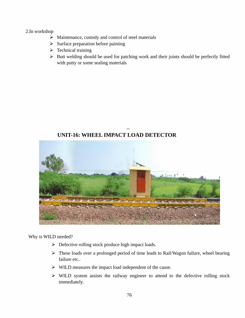
2.In workshop Maintenance, custody and control of steel materials Surface preparation before painting Technical training Butt welding should be used for patching work and their joints should be perfectly fitted
with putty or some sealing materials
--
UNIT-16: WHEEL IMPACT LOAD DETECTOR
Why is WILD needed?
Defective rolling stock produce high impact loads.
These loads over a prolonged period of time leads to Rail/Wagon failure, wheel bearingfailure etc..
WILD measures the impact load independent of the cause.
WILD system assists the railway engineer to attend to the defective rolling stockimmediately.
76

Reduces Service Failures and Unplanned Maintenance Cost of Rolling Stocks & Tracks.
WILD is used to catch the defects in the early stage and thereby protecting RailInfrastructure & avoids Catastrophic Failures.
Defects that can cause High Impact Load
Uneven loading
Coil spring weak
Shell Tread
Friction liner broken
Snubber spring broken
Axle box canting
PU/CC/EM Pad Shifted/Pressed/Perished
CC housing broken
S/Bearer roof/Friction Liner welding open
Bolster tilted one side
Defect in suspension
Broken spring Skid mark, etc.
Components of WILD
Instrumented Tracks
Signal conditioning unit
Train Trigger Sensor
Real time Embedded controller
Impact Load Analyzer Software
Wireless data transfer
Power back up
Calibration Setup
WILD Block Diagram: -
77

Measuring concept of WILD
WILD uses instrumented rails.
The spaces between sleepers are instrumented using strain gauges and any load thatappears in the effective zone is considered.
Various such measuring zones are formed along the track.
The maximum load measured in the entire instrumented portion is treated as the impactload.
As wheel of rolls over the rail various portions of the wheel fall in the effective zone anddead zone (sleepers).
As a result various diameters of wheel have different coverage.
The instrumented portions can be determined and prepositioned to give best coveragefor the wheels of interest.
Once installed the system’s wheel coverage pattern does not change.
How does WILD system flag defects
WILD system flags the defects purely based on the impact load measured.
The limits are set by the RDSO/Railway Board
Current limits
>/=20T Maintenance alarm or ILF >/=2.0 ~ <4.5
78

>/=35T Critical alarm or ILF >/=4.5
The system however features a facility for the end user to set the limits as well.
-
L4 L5 L6 L7 L8 L9L10 L11 L12 L13L14 L15
79
L16
L18 3.2 R18 3.1
L17
3.4 R17 3.3
System capabilities
Counts number of axles from various measurement channels.
Measures Average Dynamic Wheel Load for all wheels.
Determines Maximum Dynamic Wheel Load (WA) for all points of contact.
Calculates speed of each axle and the average speed of train.
Identifies and counts defective wheels as per specified thresholds and rates themaccording to the severity of defect.
Points out exact position of defective wheel from loco for easy examination.
Has solar panel providing a power backup.
Automation Features
Automatic Diagnosis of faulty channels and switching them off to avoid erroneous dataat every start.
Automatic start of Data Acquisition (DAQ) on the arrival of train in response to the starttrigger switch.
Automatic stop of DAQ after the passage of train by intelligently identifying the event.
Uploads analyzed data to remote server.
Reports in WILD
The WILD system offers the end user to generate various reports.
Month wise, Year wise, Train wise & wheel wise standard reports available.
Provision for new standard reports.
Summary reports can be drawn out based on
80

Wheel loads
Rolling stock (Engine, Wagon, Tanker etc...)
Defective rolling stock
-----
-----
UNIT – 17: TRACK PARAMETRES AT A GLANCE
1) Gauge BG a) Straight 1676±6 mm b) On curve with radius 1676+15 mm More than 440 mtrs. -06 mm c) On curve with radius less 1676 +20 mmthan 440 mtrs. – 0 mm
MG&NG a) Straight 1000+6 mm -3 mm
b) On curve with radius +15 mm more than 1000 than 290
+03 mm Mtrs. And more than 175 mtrsfor NG
c) On curve with radius 1000+20 mm
Less than 290 mtrs. And less than 175 mtrs. For NG
2) Unevenness of rail joint depression (low joint) Permissible 10mm measured on a chord of 3.5mtrs.
3) Twist- a) 2.78 mm/mtrs. For straight and curved track.
81

b) 1mm/ mtrs. For transition of curve. 4) Alignment defects – 5mm for a straight track. 5) Versine – BG speed at curve in excess of 100 km/hrs, the station to station variation of versine
a station 10mtrs apart should not exceed 15mm, for speed of 100 km/hrs and less, thevariations should not exceed 20 mm or 20% of the average versine of circular portionwhichever is more. MG –On curves which permit speed in excess of 75 km/hrs, the station to station variationthe versine ata station 10 mtrs apart should not exceed 15 mm, for speed of 75 km/ hrsand fewer variations should not exceed 20 mm or 20% of average versine of circularportion whichever is more.
6) Check rails on Curves – Check rails are provided on gauge face side of inner Rail on curvesshaper than 8º on BG, 10º on MG and 14ºon NG.
7) Wear on wing rail and the nose of crossing- a) On CMS crossing - 5.5mm for Rajdhani and Shatabdi Routes
- 7.5mm for all other Routes. b) On fabricated crossing - 4mm for Rajdhani and Shatabdi Routes
6mm for all other Routes 8) Condition of Tongue Rail - The Tongue rail should not be twisted cracked on broken up to
length of 20 mm from its toe, should not have knife edge and have more than 5mm gap inapplied condition. The maximum permitted vertical wear in 6mm.
9) Throw of the switch- Max. Min. BG 115mm 95m
m MG 100mm 89m
m
110) Check rail clearance Max. Min.
BG 48mm 44mm
MG 44mm 41mm
11) Gauge and cross level at switch assembly (point)- 1) 305 mm ahead toe and switch 2) 150 mm behind the toe of the switch 3) Middle of tongue rail 4) Heal of the switch for straight and turn out. These should be correct at all place except
heal block where it can be 6mm slack. 12) Gauge and cross level of crossing assembly-
The gauge and cross level should be checked at following locations and should always becorrect
5) 1mtrs. ahead of nose on straight and turn out.
82

6) 150 mm behind the ANC on straight and turn out. 7) 1 mtr. Behind the ANC on straight and turn out.
13) Breathing length of SEJ ± 60mm
14) Pandrol clip (MK –III ) toe load – 900- 1000 kgs load exert for a nominal deflection of 13.5mm
15) Service life of rail and UST of Rails. Gauge Rail section Service life in GMT (with test free period) BG 60kg/mtrs. 800 GMT with 25% Test free period
52kg/mtrs. 525 GMT with 25% Test free period
90R 375 GMT with 25% Test free period
MG 75R 225 GMT with 25% Test free period 16)Frequency of UST on all BG Routes
Up to 8 GMT 12 Months 8 to less than 12 9 Months 12 to less than 16 06 Months 16 to less than 24 04 Months 24 to 40 GMT 03 Months
More than 40GMT 02 Months
17) Ballast cushion Route Ballast cushion Speed
A class 300 mm 160 kmps B&C (suburban) class 250mm 130 kmps D class 200 mm 100 kmps E class
UNIT-18: WELDING
Classification of welding:-It is divided in two main sub classes:- 1.Plastic / Pressure welding 2.Fusion / without pressure welding
1 Plastic welding:-In this process, the pieces of metals to be joined are heated up to the plastic state andthen forced together by external pressure without the addition of filler material. Forge welding,resistance welding and Thermit welding with pressure are examples of this class.
2 Fusion welding:-In this case, the metal at the joint is heated to molten state and allowed to solidify. Inthis case filler material is used during welding process. This includes gas welding, ARC welding andThermit welding.
83

22.3Advantages of welding 1. A good weld is as strong as base metal. 2. General welding equipment is not very costly. 3. Portable welding equipment is available. 4. Welding permit considerable freedom in design. 5. A large no. of metal/alloys both similar and dissimilar can be joined by welding. 6. Welding can join work piece through spots as continuous pressure tight seams end to end
and in no. of other configuration. 7. Welding can be mechanised.
POINTS FOR HOW TO START THE WELDING JOB:(MANUAL METAL ARC WELDING)
1. Put on the protective clothes i.e. Apron, hand gloves, shoes guard, arm sleeves, welding screen etc. 2. In arc AC welding connect the holder to holder point and work (job) to work terminal. 3. Clean the work piece from paint, dust, grease, oil and moisture. 4. Select the diameter of the electrode as per job thickness. 5. Select the current according to the diameter of electrode. 6. In case of welding of thin section to thick section select the parameter of thin section basis. 7. Keep the work piece in easy welding position. 8. Strike the electrode on job and maintain the arc length i.e. equal to diameter of electrode. 9. Keep the electrode angle 60 degree with weld line and 90 degree with job surface. 10. Maintain the steady travel speed of electrode to form the bead. 11. Remove weld slag and clean each bead prior to making the next bead.
Essential for proper welding process 1. Correct electrode size 2. Correct current 3. Correct arc length 4. Correct travel speed 5. Correct electrode angle
Quality of welding:- Beside the steady frying and cracking sound that a correct arc produces. The shapeof the molten pool and the movement of the metal at near the pool serve as guide in checkingwelding quality. In a correctly made deposit the ripples produces on the bead will be uniform and thebead will be smooth with no overlap or undercut.
Correct electrode size: The correct choice of electrode size involves consideration of a variety offactors such as the type, position and preparation of the joint, the variety of the electrode to carryhigh current values without injury to the welding metal or less of deposition efficiency. The mass ofwork and its ability to maintain its original properties after welding. The characteristics of theassembly with reference to effect to strain set up heat application. The practicability of heat treatment
84

before and / or after welding the specific requirement as to quality and cost of achieving the desiredresults.
Correct current: If current on machine is too high or low, you are certain to be disappointed inyour welding. If too high, the electrodes melt too fast and your molten pool is large and irregular. Iftoo low, there is not enough heat to melt the base metal and your molten pool will be too small, willpile up, and look irregular. So select proper current according to job thickness and electrode size.
Correct arc length: If the arc is too long, the metal melts off the electrode in large globules whichwobble from side as the arc wavers, giving a wide spattered and irregular bad with poor fusionbetween metal and deposited metal.
WELDING PROCESS FOR STEEL IRSM44: Both Manual Metal Arc welding (MMAW)andGas Metal Arc Welding (GMAW)welding processes can be used can be used on IRS: M44. Tungsteninert gas (TIG) welding is usually used to weld the thinner plate thickness e.g. 1.0-3.0mm. The use ofcombined processes, e.g. TIG root followed by MIG/MAG filler and cap is considered as a means ofimproving both quality and productivity and shall preferably be employed.The Submerged ArcWelding (SAW) process should be used with great care keeping in view the high heat input and slowcooling rate associated with the process which can cause excessive loss of toughness in the heataffected zone.
Manual Metal Arc Welding (SMAW or MMAW): Electrical Characteristics:- D.C.E.P. (Direct Current Electrode Positive) Consumables:- Electrodes having rutile or basic flux coating are generally preferred as they reduce the
likelihood of slag inclusions. The electrode pre-heat and storage requirements (recommended by theelectrode manufacturer) must be strictly adhered to technique:
A short arc length must be maintained together with normal welding speeds to ensure that goodpenetration occurs with negligible alloy losses and no electrode overheating.
Weaving and back stepping must be avoided to reduce the heat input.
A stringer bead technique must be employed.
Current setting should be minimum as required but with the range recommended by the electrodemanufacturers.
Lead angles must be as small as possible to obtain optimum penetration.
Typical voltages andcurrents for different typesand diameters of electrodes(Horizontal Welding)
85
ELECTRODE VOLTAGE (V)
CURRENT (A)
TYPE DIA.(mm)
Rutile 1.6 2.0 2.5 3.25 4.0
19-21 20-22 20-22 21-23 21-23
30-40 40-55 60-75 95-115 120-140
Basic 1.6 2.0 2.5 3.2 4.0
24-30 24-30 24-30 24-30 24-30
35-45 45-60 65-80 100-120 130-150
Adjust for positional welding In all cases the manufacturers’ recommendations should befollowed.
1. CO2 WELDING INTRODUCTION:-MAG / CO2 (carbon-dioxide) is a variation of the standard MIG process. InMIG process, generally argon, helium or their mixtures are used for shielding the molten weld pool.Where as in co2 welding process, carbon dioxide is used as the shielding gas.
CO2 being an active gas, this process is known as MAG process. CO2 welding is used for the welding of carbon and low alloy sheets from 16 gauge (0.059
inch) to .25inch (6 mm) or heavier. It produces deeper penetration than argon or argon mixtures with slightly more spatter. CO2 have become widely popular for arc shielding or the welding of sheets. CO2 is basically a semi-automatic process, in which the arc length and the feeding of the
electrode wire into the arc automatically controlled. Less skilled welder is required in compare to TIG & SMAW process. CO2 welding may also be used in mechanised and automatic forms where producing is to be
increased and consistent quality in welding object is demanded.
WELDING EQUIPMENT : A D.C. power source and contracts. A wire feeder which contain of DC motor, speed reducing gear box,2/4 roll drive, gas
solenoid valve, potential meter. The welding gun. Shielding gas. Flow meter. Control cables. Welding cables. Hoses for gas and water. Gas preheater. Welding helmet. Glows. Apron Anti-spatter silicon spray etc.
WELDING PROCEDURE:- Correct edge preparation and joint fit up. Joint surfaces to be cleaned of rust, scale, grease or any other foreign matter. Assembling the welding equipment and setting the welding parameters. Selecting correct gun nozzle size. Setting electrode extension on the basic whether short circuiting or spray type welding is to
be done. Passing on the carbon dioxide gas supply to remove air from the hoses and then setting Co2
flow rate as per base metal and joint design.
86

It is easy to weld in the down hand position. Fillet, vertical, horizontal and overhead welds can also be made using Co2 welding. After the weld is complete, the end crater should be filled.
ADVANTAGES:- Higher welding speeds. Better and deep joint penetration with good bead control and little tendency to undercut as
compound to argon. Sound welds deposits which can be made consistently. Lower associated cost as Co2 is relatively less expensive. Despite the oxygen in Co2, porosity is not a issue when a suitably deoxidized wire (electrode)
and reasonably short arc used. Good mechanical properties of weld metal.
DISADVANTAGES:- Co2 produces a rather harsh arc. Spatter is expensive unless a very short, uniform arc length is maintained, keeping the tip of
the electrode below the surface of the work properly adjusting the power supply inductancesetting also minimises spatter.
High impact properties in weld metals can’t be achieved.
2. METAL INERT GAS ARC WELDING (MIG)/ GASMETAL ARC WELDING (GMAW)
PRINCIPLE OF OPERATION: - It is an arc welding process where in coalescence is producedby heating the job with an electric arc establishment between continuously fed metal electrode andthe job. No flux is used but the arc and molten metal arc shielded by an inert gas, which may beargon, helium,Co2 or a gas mixture. Before igniting the arc, gas flow is checked. Proper current andwire feed is set and the electrical connections are ensured. The arc is struck by any one of the twomethods. In the first method, current and shielding gas flow is switched ` on’ the electrode isscratched against the job as usual practice for striking the arc. In the second method, electrode ismade to touch the job, is retracted and then moved forward to carry out welding, but before strikingthe arc, shielding gas, and current is switched on. About 15mm length of the electrode is protectingfrom the torch before striking the arc. During welding torch remains about 10-12mm away from thejob and arc length is kept between 1.5 to 4mm. Arc length is maintained constant by using theprinciple of self-adjusted arc and controlled arc in semi-automatic (manually operated) andautomatic welding sets respectively. MIG welding is very versatile in that a wide range of materialthickness and positions can be accommodated. Weld quality and weld speeds that can be achievedare with high with MIG/MAG welding. Lack of side wall fusion problems commonly associatedwith process must be guarded against by providing proper angle to the arc.
EQUIPMENT:- Welding power source and cables. Welding torch and wire electrode coiled on a spool.
87

Wire feed mechanism and controls consisting of a pair of driving rolls, electric motor etc. Shielding gas cylinder, pressure regulator and flow meter. Controls for switching on and off the currents, electrode wire and inert gas.
Electrical characteristics:-D.C.E.P. (Direct Current Electrode Positive) Consumables:-Filler wire:- The austenitic stainless steel consumable wires are recommended. Typical Welding Parameters for MIG Short Arc and Spray Arc Welding.
Type of Arc
Position Wire Diameter (mm)
Current (A)
Voltage (V) Speed (mm/sec)
Short Arc Flat 0.8 130-140 22-24 3.0-4.5 Vertical 0.8 110-130 20-22 3.0-4.5
Spray Arc Flat 1.6 325-375 25-28 3.0-4.5
It is recommended that the mechanical properties achieved by welding with this process becarefully evaluated in terms of the joint requirements. The welding should be in any case beingcarried out in accordance with an approved welding procedure. Shielding Gas:-The shielding gas should be an argon 1 to 2% oxygen mixture. Argon basedshielding gases containing a maximum of 5% carbon dioxide has been successfully used. Gasescontaining higher carbon dioxide concentration will require procedure testing.Gas flow rate undershielded welding conditions must be at least 14 litre/min. higher gas flow rates will be required ifwelding is being carried out in draughty or exposed conditions( too much is too bad as too low).
MIG/ GMAW WELDING DIAGRAM
ADVANTAGES:-
88

Because of continuously fed electrode, MIG welding process is much faster as compared toTIG or stick electrode welding.
Produce joints with deep penetration. Thick and thin type of work pieces can be welded effectively. Large metal deposition rates are achieved by MIG weld process. The process can be easily mechanised. No flux is used, MIG welding produces smooth, neat clean and spatter free welded surfaces
which require no further cleaning, welding cost reduces. Higher arc travel speed associated with MIG welding reduces distortion considerably.
DISADVANTAGES:- The process is slightly more complex as compared to TIG or stick electrode welding because
no of variable like- electrode stick out, torch angle, welding power etc. are required to becontrolled effectively to achieve good results.
Welding equipment is more complex, more costly, and less portable. Since air drafts may disperse the shielding gas, MIG welding may not work well in outdoor
welding applications. Weld metal cooling rates higher than with the process that deposit slag over the weld metal.
3. TUNGSTEN INERT GAS ARC WELDING (TIG) OR GAS TUNGSTEN ARC WELDING (GTAW)
PRINCIPLE OPERATION: - It is an arc welding process where in coalescence is produced by“Heating the job with an electric arc between a tungsten electrode and a job. A Shielding gas is usedto avoid atmospheric contamination of the molten weld pool. A filler metal may be added, ifrequired. Welding current, water and inert gas supply are turned on. The arc is struck either bytorching the electrode with a scrap metal tungsten piece or using a high frequency unit. In the firstmethod arc is initially struck on a scrap metal piece and then broken by increasing the arc length.This procedure repeated twice or thrice warms up tungsten electrode. The arc is then struck betweenthe electrode and pre-cleaned job to be welded. This method avoids breaking electrode tip, jobcontamination and tungsten loss. Weld puddle is developed due to arc action on the job.
Welding torch is moved back. Filler rod is moved ahead and filler metal is added to the weld puddle. Filler rod is withdrawn. Torch is moved to the leading edge of the puddle.
NOTE:- Job before welding is cleaned off all air ,grease, paint, rust, etc. either mechanically orchemically.
EQUIPMENT:- Welding torch, Tungsten electrode, filler materials. Welding power source, high frequency unit, DC supply unit, Cables.
89

Inert gas cylinder, pressure regulator and flow meter. Cooling water supply. Water and gas solenoid valves. This process is generally limited to sheet up to 2.5mm. TIG welding is also used for fusion of
the root run on heavy gauge weldments. In order to ensure adequate ductility in the world, asuitable austenitic filler wire should be used.
Electrical characteristics:-D.C.E.P.( Direct Current Electrode Positive) Electrode-1-2% throated tungsten using a 30-60 vertex angle (pointed tip) for optimum
welding penetration for the least current used. Gas:-Pure argon must be used as the shielding gas typical flow rates are between 8 and 14
l/min.
APPLICATIONS:- Welding Aluminium, Mg ,Copper ,Nickel and their alloy Carbon alloy or stainless steel,
inconel, high temp and hard surfacing alloys like Zirconium, titanium etc. Welding sheet metal and thinner sections. Welding of expansion bellows, transistor cases, instrument diaphragms and cansending
joints. Precision welding in atomic energy, air craft, chemical and instrument industries. Rocket
motor chamber fabrication in launch vehicle.
ADVANTAGES:- No flux is used, hence is no danger of flux entrapment. When welding refrigerator and air
conditioner components. Because of clear visibility of the arc and the job, the operator can exercise. This process can weld in all positions and produces smooth and sound welds with less spatter. TIG welding is very much suitable for high quality welding of thin materials (As thin as
0.125mm). It is very good process for welding nonferrous metals and stainless steel.
DISADVANTAGES:- Under similar applications, MIG welding is a much faster process as compared to TIG
welding, since TIG welding requires a separate filler rod. Tungsten if it transfers to molten weld pool can contaminate the same. Tungsten inclusions
are hard and brittle. Filler rod end of it by chance comes out of the inert gas shield can cause weld metal
contamination. Equipment costs are higher than that for flux shielded metal arc welding.
PLASMA ARC CUTTING
WHAT IS PLASMA: One common description of plasma is that it is the fourth state of matter.We normally think of the three state of the matter as Solid, Liquid & Gas.
90

For the most commonly known substance water, these states are ice, water and steam. If you add heat energy, the ice will change from a solid to a liquid and if more heat is added it
will change to a gas (steam). When substantial heat added to a gas, it will change from gas toplasma the forth state of matter.
If you boost a gas to extremely high temperature you get plasma. The energy begins to breakapart the gas molecules and atom begins to split. Normally atom ismade up of proton andneutrons in the nucleus.
In plasma the electrons separates from the nuclease. Once the energy of heat releases theelectrons from the atom, the electrons begin to move around quickly.
The electrons are negatively charged and they leave behind their positively charged nuclei.These positively charge nuclei are known as ions.
By adding energy to water it separates into hydrogen and oxygen, further addition of moreenergy the ionization of gases takes place and creation of free electrons and ions takes place.This is called plasma and it is conductive of electricity due to availability of free electrons.
PLASMA ARC CUTTING
What is plasma cutting?
This is a cutting system utilizing heat generated
by arc discharge between the cutting object
material and the electrode inside the torch. Arc
discharge heat forms working gas into the
plasma state of high temperature; the plasma
jet of high temperature and high-speed is
blown out from the nozzle; and the cutting
object material is fused to be cut.
Process
A plasma torch requires you to start an arc
between the electrode in the torch and the work
you intend to cut. To start this arc there are various methods used, commonly High Frequency
91
or Blow Back. HF (High Frequency) is used in most modern industrial plasma systems and in
many older systems. The second common method is known as blow back, or short circuit start.
In a high frequency plasma system there are no moving parts in the torch. The electrode is
connected to the power source's negative output and the work connected to the positive. The
electrode is the conductor from which the arc starts and travels to the work piece. To start the
arc the plasma initially connects the nozzle to positive. The nozzle is responsible for directing
the gas flow, it wraps around the electrode and has a small output hole inwhich the gas flow
and the plasma arc is directed. A DC potential between the nozzle and electrode is established
and the HF circuit is turned on. The high frequency, high voltage causes a small low current
arc to transfer between the nozzle and electrode in the torch. The low HF current creates a path
of ionized gas allowing the lower voltage DC output to conduct. The current established
between the nozzle and electrode in the torch is known as a Pilot Arc.
In the blow back method the arc is started with the plasma torch's electrode and nozzle initially
touching. The power source draws a current from the nozzle to the electrode. After the current is
established the power source will turn on the gas flow. Due to the design of the torch when gas begins to
flow the electrode will pull away from the nozzle. As the electrode retracts the current draw between it
and the nozzle will create a spark. With this ionized path of gas, lower voltage DC current is allowed
flow and once again has a Pilot Arc.
In both methods above you achieve a pilot arc, which is an ionized path of gas between the electrode
and nozzle in the torch. Once this pilot arc is brought close to the work, which is at the same potential as
the nozzle, current will transfer directly from the electrode to the work. The plasma source will detect
the current into the work and disconnect the nozzle (in most cases) allowing full current flow from the
electrode to nozzle.
Plasma is an effective means of cutting thin and thick materials alike. Hand-held torches can usually cut
up to 38mm thick steel plate, and stronger computer-controlled torches can cut steel up to 150 mm thick.
Since plasma cutters produce a very hot and much localized "cone" to cut with, they are extremely
useful for cutting sheet metal in curved or angled shapes.Through a small channel pressurized gas such
as argon, nitrogen, air is sent. At the centre of channel there is a negatively charged electrode. As the gas
passes through spark is produced in channel and the gas is converted to plasma. The temperature of this
plasma is upto 17,000 0C and speed at which it travel 20,000 feet per second. The plasma is sufficiently
hot to melt the metal being cut and moves sufficiently fast to blow molten metal away from the cut. The
plasma itself conducts electrical current. The cycle of creating the arc is continuous as long as power is
supplied to the electrode and the plasma stays in contact with the metal that is being cut.
92

TYPES OF PLASMA ARC CUTTING 1. AIR PLASMA CUTTING
Air is used as plasma forming gas. The electrode material is hafnium or zirconium, which is mounted on copper holder. Air for cooling the torch is also used. It is used because it is cheaper. The disadvantage is erosion at a faster rate of electrode material.
DUAL FLOW PLASMA ARC CUTTING
Duty Cycle-100@40% Size- 490’ 270’375 Quality cut- 8mm Gas - compressed air
Advantages of Plasma Arc cutting:1. It cuts carbon steel upto 10 times faster than Oxy-fuel cutting, with equal quality more
economically.2. It leaves a narrower kerf.3. Plasma cutting being primarily a melting process, can cut any metal.4. Arc Plasma torches give the highest temperature available from many practicable sources. The
energy seems to be unlimited in this method.
Disadvantages of Plasma Arc cutting:1. High initial cost of the equipment.
Applications of plasma arc cutting:
93

i) Plasma cutting is used to cut particularly those nonferrous and stainless metal that cannot becut by the usual rapid oxidation induced by ordinary flame torches
ii) Plasma cutting can be used for stack cutting ,plate bevelling, shape cutting and piercing
iii) With some modifications, plasma arc cutting can be used under water.
iv) Plasma arc cutting finds application in many industries such as ship-yards, chemical, nuclearand pressure vessels.
v) It is used for removing gates and risers in foundry.
vi) It cuts hot extrusions to desired length.
vii) It is used to cut any desired pipe contour.
viii) It is also employed for gouging applications.
ix) It finds use in the manufacture automotive and rail road components.
COMMON DEFECTS WELDING- CAUSES AND REMEDIAL MEASURES
WELDING DEFECT-welding is said to be defective if it not as per specifications or it is not fulfilling thecustomer requirements. The defect and their remedial measures for welds made by the GMAW, MMAW andother similar welding process are as follows.
DEFECTS CAUSES REMEDIAL ACTION
1.Lack of penetration 1.Too little heat input in the weld area
1. Increase the current and Reduce stick out.
2.Excessive welding speed 2. Reduce strike out
3. Improper edge penetration 3. Follow the specified edge penetration
4. Poor arc manipulation 4. Use proper techniques
5.Excessive arc gap 5. Maintain the correct arc gap
6.No root gap or less root gap 6. Maintain the correct root gap
2.Excessive penetration ( or burn through)
1. Too much heat in the weldarea. 1. Reduce the current area increasethespeed of travel.
2. Too narrow root opening or noRoot opening.
2. Make sure that the root openingand root face are correct.
3. Narrow arc gap or stick out. 3. Increase the stick out weaving ofthe welding gun.
4. Improper electrode selection. 4. Pick up the correct electrode orfillerwire diameter.
3.Lack of fusion 1. Improper torch handing 1. Direct the arc that it covers allareasof the joint the arc, not thepuddleshould do the fusion.
94

2. Low heat and high travel speed. 2. Keep the electrode at the leadingEdge of penetration.
3. Arc is being directed at the base. 3. Check current values properly.
4. Improper electrode/ filler wireSelection.
4. Select the filler metal as per baseMetal specifications.
4.Spratters 1. High current 1. Use correct current
2.Long arc 2. Maintain low and stable arc.
3.Irregular and stable arc 3. Maintain low and stable arc.
4.Excessive weaving 4. Avoid excessive weaving.
5.Undercut 1. Faultyelectrode manipulation. 1. Use a uniform weave in welding.
2. Improperelectrode angle. 2. Maintain the proper electrodeangle.
3.Faulty electrode usage 3.Avoid excessive weaving
4. Current too high. 4.Use moderate current and weldSlowly.
6.Blow holes/porosity 1. Contamination by the atmosphere and other materials i.e. oil, dirt, rust and paint etc.
1. Clean the job well before the Welding.
2.Change in the physical qualities of The filler wire due to excessivecurrent.
2. Use proper filler rod.
3.Entrapment of the gas evolved during weld metal solidification.
3. Use proper speed of travel.
4.Loss of shielding gas because of too fast travel.
4.Use proper flow rate of shielding Gas.
5.Shielding gas flows rate too low, not providing full protection.
5.Proper welding technique and Shielding gas.
6.Shielding gas flow rate too high, drawing air in to the arc area.
6. Adjust accurate gas flow rate.
7.Wrong type of shielding gas beingused.
7.Control the impurities percentage in gas as per specification.
8.Gas shield blow away by wind/storms.
8.Do not weld in the wind or under The fan.
7.CRACK 1. Low temperature of base metal. 1.Raise the temperature of baseMetal.
2.Sudden cooling of the weld bywater or other means.
2. Avoid such type of operation.
3. Lessthroat thickness. 3. Maintain specified throatthickness.
4. Crack generation due to crater. 4. Fill up the crater.
8.OVER LAPPING 1.Low current in butt joint and high current in tjoint/fillet joints.
1.Maintain the specified current as per joint.
2. Too low welding speed. 2. Increase the welding speed. 3.Improper filler wire/electrode angle.
3. Maintain the proper angle.
95

9.SLAGINCLUSION
1.Moisture content in the filler metal/ flux.
1. Preheat the filler metal/flux.
2. Wrongarc manipulation. 2. Maintain uniform and stable arc.
3. Improper cleaning in multi-layerwelding in MMAW.
3. Clean the previous bead from theslag before depositing next layer.
10. CRATER It occurs due to end of the bead orconsumption of electrode in MMAW.
1.Fill up the crater at the end of thebead/ electrode finishing point byjust moving the electrode in backward direction.
11.POORAPPEARANCE
1. Faulty filler road. 1. Use proper weld techniques.
2. Overheating. 2. Avoid overheating.
3. Wrong arc/current and voltage. 3. Use moderate parameters.
4. Wrongarc manipulation. 4. Use a uniform weave and speed. 12.DISTORTION 1. Shrinkagewelds metal. 1. Weld rapidly.
2. Faulty clamping. 2. Clamping properly.
3. Faulty preparation. 3. Adopt a welding procedure.
4. High heat input at weld joint. 4. Use moderate current and voltage.
5. Improper welding sequence. 5. Adopt correct welding sequence.
6. Use post heating or peening torectify the distortion effect.
7.Use pre-bending technique to control the distortion.
SAFETY RECOMMONDATION FOR INSTALLATION AND OPERATION OF GAS WELDINGAND CUTTING EQUIPMENT
1. Acetylene cylinders must always be kept upright.2.A cap must be fitted on the cylinder while it is not in use3. Cylinders should not be used as supports for heavy loads or as rollers for moving materials.4. Cylinders should be stored in a well-protected, well ventilated, dry location, well away from highly
combustible materials such as oil and excelsior.5. Cylinders containing Acetylene and Oxygen should be stored separately or quite for apart from each
other.6. Do not use a hammer or wrench to open any valve on a cylinder.7. One should not smoke at the place where gas cylinders have been stored.8. Water, dirt, oil and grease should not be permitted to come in contact with oxygen cylinders, valves,
regulators, hose or fittings. Do not handle oxygen cylinders with oily hands or oily gloves.9. Cylinders valve shall be closed when worked is finished.10. Do not tamper with the safety devices provide in cylinders or valves.11. Never use acetylene or oxygen without proper pressure regulators.12. Before connecting to pressure regulators to cylinder valve, the valve shall be opened slightly and
closed immediately. This action which is termed as Cracking clears the valve of dirt or dusts thatotherwise enters the pressure regulators. Stand to one side of the outlets while cracking.
13. Open cylinder valve slowly and let the cylinder key for opening valve remain on valve stem so thatcylinders may be quickly turned off it an emergency arises.
96
14. To test for leaks a solution of soap and water may be brushed on the valve socket and glandnut.Bubbles indicate leakage.
SAFETY RECOMMONDATION FOR INSTALLATION AND OPERATING OF ARC WELDINGAND CUTTING EQUIPMENT ARCWelding Machines
1. Arc welding machines should be of suitable quality.2. Arc welding machine should be properly grounded (earthed).3. Proper terminals should be used on the arced welding machines for the power line voltage
connection.4. One should not work on the wiring of an arc welding machines unless qualified to do so.
In the case of AC arc welding machines:1. In transformers, the secondary circuit shall be thoroughly insulated from the primary.2. Welding (secondary) terminals shall be so arranged that current carrying parts arenot exposed to
accidental contact.3. In a transformer the welding circuit should be quite separate from the power circuit,so that there is no
risk of worker suffering serious shocks or burns through power voltage appearing across theelectrode holder.
4. Control apparatus provided with the welding machines shall be enclosed except for the operatingwheels, levers etc.
5. Transformer welding be suction or compressed air cleaned periodically.6. Greasing points need attention periodically.7. Switch contacts should be cleaned periodically.8. Before under taking any maintenance work on welding machines, disconnect them from the main
supply.
OTHER ARC WELDING EQUIPMENTS:1. Electrode Holder-
A. Electrode holder should be soundly connected to the welding lead. They should be of adequaterating for the maximum welding currents to prevent them from heating up and becoming too hot tohandle.B. Insulation of all metallic and current carrying parts, including the jaws which grip the electrodes,is recommended.
2. Welding Cables – Welding Cables shall be of completely insulated, flexible type.3. The body or the frame of the welding machine shall be efficiently earthed.4. Earthing cable should be connected to the job as nearest as possible.5. Avoid earthing cable connection at rail lines, wheels, bearings, CBC and other Sensitive parts of coach & wagon.
PROTECTION OF WORKERS: Workers need to be protected from:-1. The welding rays.2. Flying sparks, metal globules (spatter), hot slag particles and hot electrode stubs.3. Fumes and gases when welding in confined space.
97

4. Falling when welding at a height from the ground.So workers should wear personnel protective equipments (PPE) to protect from hazardous happenings.
What type of PPE is available when welding? The chart below summarizes the types of personal protective equipment that can be used when welding. Welding - Personal Protective Equipment Body Part Equipment Illustration Reason Eyes and face Welding
helmet, hand shield, or goggles
Protects from: radiation hot slag, sparks intense light irritation and chemical burns
Wear fire resistant head coverings under the helmet where appropriate
Lungs (breathing)
Respirators Protects against: fumes and oxides
Exposed skin(other than feet, hands, and head)
Fire/Flame resistant clothing and aprons
Protects against: heat, fires burns Notes: pants should not have cuffs, shirts should have flaps overpockets or be taped closed
Ears - hearing
Ear muffs, earplugs
Protects against: noise
Use fire resistant ear plugs where sparks or splatter may
98

enter the ear. Feet and hands
Boots, gloves Protects against: electric shock heat burns fires
99