Air Suspension in DEMU & Fiat Bogie
27
Air Suspension in DEMU & Fiat Bogie 1 Presented By: STC/NBQ
Transcript of Air Suspension in DEMU & Fiat Bogie

Air Suspension in
DEMU & Fiat
Bogie
1
Presented By:
STC/NBQ

Introduction
• Air Suspension system, as secondary suspension,
in DEMU coaches is far superior to conventional
secondary suspension & provides –
Better riding comfort
Improved reliability and reduced maintenance
Capacity to sustain super dense crush load
Constant floor height of coach.
Great durability
Ride index with Air springs is 2.72 against 3.37
in steel coil springs
2

View of Air Suspension
3

Necessity for Air Suspension • In suburban trains like DEMU, the number of passengers
entraining (Super Dense Crush Load) in to the coach cannot be controlled and hence the payload of the coach increases from 18 tons to 34 tons.
• This abnormal increase of payload reduces the Riding Clearances between the Coaches and Wayside platforms and also reduces buffer height resulting in severe hitting of coach on the plat forms.
• Due to the Super Dense Crush Load the bolster springs become solid, which in turn damages / breaks the Coil springs resulting in discomfort to the passengers.
• To overcome the above problems, Air Suspension (Air spring) is introduced in DEMU Coaches.
•
4

Riding Clearance under Normal Load
&
under Super Dense Crush Load
5

Super Dense Crush Load (SDCL)
• Pneumatic suspension is introduced in the
secondary suspension to maintain a constant
buffer height irrespective of loaded
conditions by varying the pressure of air
inside the Air Spring
• Super Dense Crush Load (SDCL)
= Seated capacity
+
Standing load @ 16 persons/sqm.
6

Parts of Air Suspension
• Emergency spring
• Leveling valve
• Adjustable screw rod
• Duplex Valve
• Main Air Reservoir
• Auxiliary Reservoir
• Isolating Cock
7

Fitting of Air Suspension
8

Schematic Diagram of Air
Suspension equipments
9

Levelling valve: • The levelling valve is fitted with Top bolster and
is designed to move up and down along with
bolster. Under normal condition, it is designed to
take LAP position.
10

• It connects the main reservoir with Air spring and
admits more air, whenever the bolster comes down due
to abnormal increase in the Pay load (Super Dense
Crush load).
11
• It also connects the air springs with exhaust to release
the excess air from air spring, whenever the bolster goes
up due to reduction in the Pay load after detraining of
passengers from the coach.
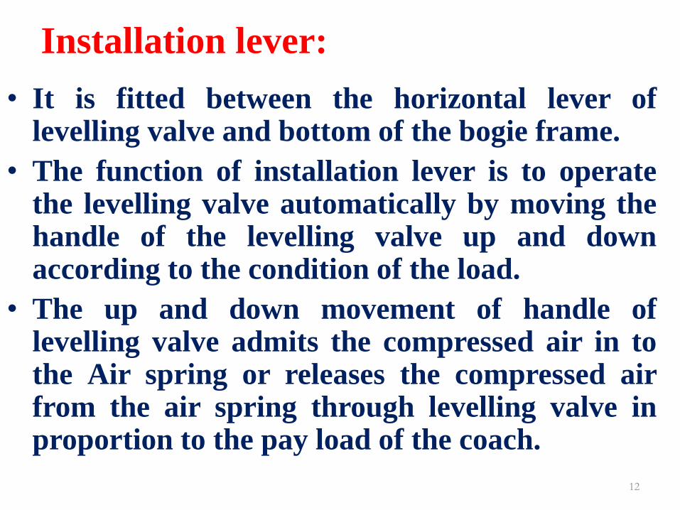
Installation lever: • It is fitted between the horizontal lever of
levelling valve and bottom of the bogie frame.
• The function of installation lever is to operate the levelling valve automatically by moving the handle of the levelling valve up and down according to the condition of the load.
• The up and down movement of handle of levelling valve admits the compressed air in to the Air spring or releases the compressed air from the air spring through levelling valve in proportion to the pay load of the coach.
12

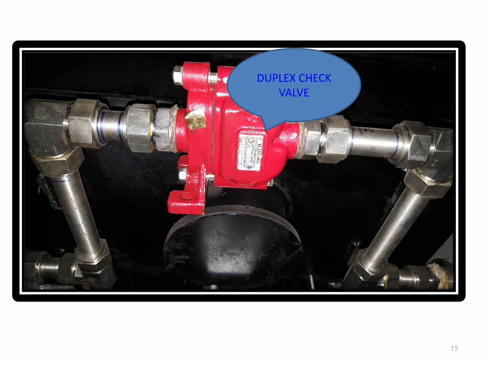
Duplex Valve: • It is a double check valve provided between the two Air
springs of same bogie.
• It operates with a Pressure differential of 1.5 Kg/cm2.
• It comprises of two check valves side by side, arranged
so that air can flow in either direction whenever the air
pressure differential exceeds the pre-set value of 1.5
Kg/cm2.
• Both the check valves of Duplex valve remains closed, if
the pressure between the two springs is within present
value.
13
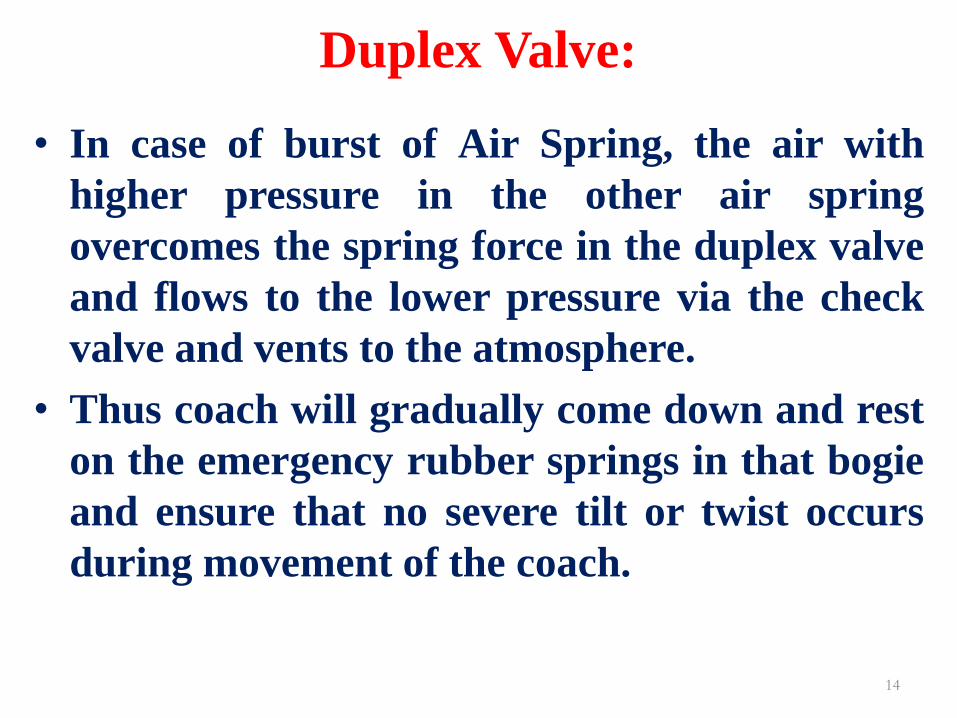
Duplex Valve:
• In case of burst of Air Spring, the air with
higher pressure in the other air spring
overcomes the spring force in the duplex valve
and flows to the lower pressure via the check
valve and vents to the atmosphere.
• Thus coach will gradually come down and rest
on the emergency rubber springs in that bogie
and ensure that no severe tilt or twist occurs
during movement of the coach.
14
15
DUPLEX CHECK VALVE
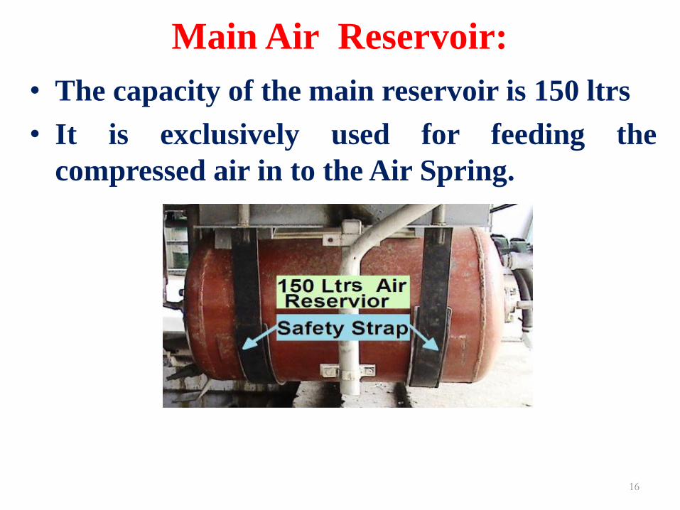
Main Air Reservoir:
• The capacity of the main reservoir is 150 ltrs
• It is exclusively used for feeding the
compressed air in to the Air Spring.
16

Auxiliary Reservoir
• It is fitted with the Air Spring.
• The capacity of this reservoir is 20 Ltrs for
DEMU and 40 Ltrs. for Fiat Bogie.
• There is an orifice kept between air spring
and additional reservoir. It acts as an Air
damper to over come vertical and lateral
oscillations so as to increase the riding
comfort.
17

Emergency Springs:
• The function of emergency spring is to
support the top bolster to prevent tilt of
coaches whenever the Air spring burst.
18

Isolating cock
• The isolating cocks are provided in the
pneumatic suspension system at
predetermined locations to stop the air supply
in either bogies in the main reservoir for
under taking local repairs.
• The total number of cocks required per coach
is 3(three).
19

Non -return valve
• The check valve provided in the system is a non
return valve which allows the air to flow uni-
directionally from feed pipe to main reservoir in
the event of failure or breakage in the feed pipe,
the check valve will not allow the air to flow off
of the pneumatic suspension system and thus
keep the system operative for sometime.
• The total number of check valve required per
coach is 1(one).
20
Working Principle of Pneumatic Suspension
• Air suspension is a suspension where
properties of air are used for cushioning effect (springiness).
• Enclosed pressurised air in a pre-defined chamber called air spring, made up of rubber bellow & emergency rubber spring, provides various suspension characteristics including damping.
• Air springs are height-controlled load levelling suspension devices. With changing loads, air spring reacts initially by changing the distance between air spring support and vehicle body.

Working Principle of Pneumatic Suspension
• The leveling valve is in turn actuated, either
taking the compressed air pressure to the air
spring or releasing air pressure from it to the
atmosphere.
• This process continues until the original height
is restored. This mechanism ensures a constant
floor height on coaches provided with air
springs, irrespective of the load.
• This greatly reduce problems associated with
low buffer / coupler heights.

Introduction of FIBA DEVICE in 1600 HP DEMU & FIAT Bogie
(FAILURE INDICATION CUM BRAKE APPLICATION) DEVICE

Development of FIBA device for ICF,
LHB and Hybrid Coaches OBJECTIVE FOR DEVELOPMENT OF FIBA DEVICE:
• To develop a fail-safe system which can immediately and automatically reduce the speed of train by applying the brake and stop within a reasonably safe distance in the event of the air spring getting deflated due to bursting or any other reason.
• To provide a positive indication to the driver and the crew of the train by whistling sound and indication on both sides of the train through indicators on that particular coach.
• To provide means to enable the train to run at a restricted speed (max. 60 km/hr) upto the desired destination.

Current Design of FIBA Device
• FIBA device works on pure pneumatic circuit. 01(One) device works for one bogie; hence each coach is fitted with 2 (two) nos. of FIBA devices for visual signal. (02 nos. brake indicators connected with one FIBA device)
• The equipment is designed to sense the bellow pressure on continuous basis. As soon as the pressure of any spring reduces to 1+0.1 Kg/Cm2, the concerned FIBA valve actuates and connects BP to atmosphere. In such a situation full service brakes are applied, hissing sound starts and Indicators turn to Red.
The crew is required to identify the FIBA valve actuated and close the BP isolating cock of FIBA system to stop the venting of air from BP line. The hissing sound stops. The Air spring system of the bogie is to be isolated through isolating cock in FP line and train can be moved.

PRESSURE SENSOR

27