
TECHNICAL BULLETIN INSTALLATION INSTRUCTIONS ... - NSN · PDF filetechnical bulletin...
162
TECHNICAL BULLETIN INSTALLATION INSTRUCTIONS FOR EPLRS NETWORK MANAGER VEHICLE WITH AMTECH TOP FOR SYSTEMS SINGLE CHANNEL GROUND AND AIRBORNE RADIO SYSTEM (SINCGARS) AN/VRC-92F FORCE XXI BATTLE COMMAND, BRIGADE-AND-BELOW (FBCB2) AN/UYK-128 (V)4 PRECISION LIGHTWEIGHT GPS RECEIVER (PLGR) AN/PSN-11 ENHANCED POSITION LOCATION REPORTING SYSTEM (EPLRS) AN/VSQ-2 (V) QUICK-ERECT ANTENNA MASTS (QEAM) REMOTE REKEY DEVICE KOK-13 NETWORK MANAGER AND PRINTER SUPPLEMENTAL BATTERIES FOR VEHICLES TRUCK, UTILITY, 2/4-DOOR: HEAVY VARIANT, 1-1/4 TON, 4X4, M1097A2 (2320-01-380-8604) (EIC: BB6). Approved for public release; distribution is unlimited. TB 9-2320-280-35-12 HEADQUARTERS, DEPARTMENT OF THE ARMY FEBRUARY 2006
Transcript of TECHNICAL BULLETIN INSTALLATION INSTRUCTIONS ... - NSN · PDF filetechnical bulletin...
TECHNICAL BULLETININSTALLATION INSTRUCTIONS
FOR EPLRS NETWORK MANAGER VEHICLE WITH AMTECH TOP
FOR SYSTEMS
SINGLE CHANNEL GROUND AND AIRBORNE RADIO SYSTEM (SINCGARS)
AN/VRC-92F
FORCE XXI BATTLE COMMAND, BRIGADE-AND-BELOW (FBCB2)AN/UYK-128 (V)4
PRECISION LIGHTWEIGHT GPS RECEIVER (PLGR)AN/PSN-11
ENHANCED POSITION LOCATION REPORTING SYSTEM (EPLRS)AN/VSQ-2 (V)
QUICK-ERECT ANTENNA MASTS (QEAM)
REMOTE REKEY DEVICEKOK-13
NETWORK MANAGER AND PRINTER
SUPPLEMENTAL BATTERIES
FOR VEHICLES
TRUCK, UTILITY, 2/4-DOOR: HEAVY VARIANT, 1-1/4 TON, 4X4, M1097A2 (2320-01-380-8604) (EIC: BB6).
Approved for public release; distribution is unlimited.
TB 9-2320-280-35-12
HEADQUARTERS, DEPARTMENT OF THE ARMY
FEBRUARY 2006

*ARMY TM 9-2320-280-20-1AIR FORCE TO 36A12-1A-2092-1-1
MARINE CORPS TM 2320-20/7B
HEADQUARTERS CHANGE DEPARTMENT OF THE ARMY,NO. 1 Washington, D.C., 1 OCTOBER 2006
TECHNICAL BULLETININSTALLATION INSTRUCTIONS
FOR EPLRS NETWORK MANAGER VEHICLE WITH AMTECH TOPFOR SYSTEMS
SINGLE CHANNEL GROUND AND AIRBORNE RADIO SYSTEM (SINCGARS)
AN/VRC-92F
FORCE XXI BATTLE COMMAND, BRIGADE-AND-BELOW (FBCB2)AN/UYK-128 (V)4
PRECISION LIGHTWEIGHT GPS RECEIVER (PLGR)AN/PSN-11
ENHANCED POSITION LOCATION REPORTING SYSTEM (EPLRS)AN/VSQ-2 (V)
QUICK-ERECT ANTENNA MASTS (QEAM)
REMOTE REKEY DEVICEKOK-13
NETWORK MANAGER AND PRINTER
SUPPLEMENTAL BATTERIES
FOR VEHICLES
TRUCK, UTILITY, 2/4-DOOR: HEAVY VARIANT, 1-1/4 TON, 4X4, M1097A2 (2320-01-380-8604) (EIC: BB6).
TB 9-2320-280-35-12, 28 February 2006, is changed as follows:1. Remove old pages and insert new pages as indicated below.2. New or changed material is indicated by a vertical bar in the margin of the page.
Remove pages Insert page
A/(B blank) A/(B blank)i through iv i through iv4-3 through 4-8 4-3 through 4-85-11 through 5-16 5-11 through 5-165-49 and 5-50 5-49 and 5-505-53 and 5-54 5-53 and 5-545-59 and 5-60 5-59 and 5-60None 5-107 through 5-117/(5-118 blank)DA Form 2028 DA Form 2028
3. File this change sheet in front of the publication for reference purposes.
Approved for public release; distribution is unlimited.
TB 9-2320-280-35-12

Distribution:
To be distributed in accordance with the Initial Distribution Number (IDN) 344840 requirements for TB 9-2320-280-35-12.
By Order of the Secretary of the Army:
PETER J. SCHOOMAKERGeneral, United States Army
Chief of Staff
Official:
JOYCE E. MORROWAdministrative Assistant to the
Secretary of the Army0620103

TB 9-2320-280-35-12
LIST OF EFFECTIVE PAGES
NNOOTTEEA vertical line in the outer margins of the page indicates theportion of text affected by the change.
Dates of issue for original and change pages are:
Original . . . . . . . . . . 0 . . . . . . 28 February 2006
Change . . . . . . . . . . 1 . . . . . . . . 1 October 2006
TOTAL NUMBER OF PAGES IN THIS PUBLICATION IS 151 PAGES.
Page No.. . . . . . . . . . . . . . . . . . . . . . . . *Change No.A/(B blank) . . . . . . . . . . . . . . . . . . . . . . . . . . . . . . . 1i through iv . . . . . . . . . . . . . . . . . . . . . . . . . . . . . . . 11-1–4-2 . . . . . . . . . . . . . . . . . . . . . . . . . . . . . . . . . . 04-3–4-4 . . . . . . . . . . . . . . . . . . . . . . . . . . . . . . . . . . 14-5 . . . . . . . . . . . . . . . . . . . . . . . . . . . . . . . . . . . . . . 04-6–4-8 . . . . . . . . . . . . . . . . . . . . . . . . . . . . . . . . . . 14-9–5-11 . . . . . . . . . . . . . . . . . . . . . . . . . . . . . . . . . 05-12 . . . . . . . . . . . . . . . . . . . . . . . . . . . . . . . . . . . . . 15-12.1–5-12.4 Added. . . . . . . . . . . . . . . . . . . . . . . . 15-13 . . . . . . . . . . . . . . . . . . . . . . . . . . . . . . . . . . . . . 15-14 . . . . . . . . . . . . . . . . . . . . . . . . . . . . . . . . . . . . . 05-15 . . . . . . . . . . . . . . . . . . . . . . . . . . . . . . . . . . . . . 15-16–5-49 . . . . . . . . . . . . . . . . . . . . . . . . . . . . . . . . 05-50 . . . . . . . . . . . . . . . . . . . . . . . . . . . . . . . . . . . . . 15-51–5-53 . . . . . . . . . . . . . . . . . . . . . . . . . . . . . . . . 05-54 . . . . . . . . . . . . . . . . . . . . . . . . . . . . . . . . . . . . . 15-55–5-59 . . . . . . . . . . . . . . . . . . . . . . . . . . . . . . . . 05-60 . . . . . . . . . . . . . . . . . . . . . . . . . . . . . . . . . . . . . 15-61–5-106 . . . . . . . . . . . . . . . . . . . . . . . . . . . . . . . 05-107–5-117/(5-118 blank) Added . . . . . . . . . . . . . 1A-1/(A-2 blank) . . . . . . . . . . . . . . . . . . . . . . . . . . . . 0
*Zero in this column indicates original page.
A/(B blank) Change 1

i
TB 9-2320-280-35-12
TECHNICAL BULLETIN HEADQUARTERS,NO. 9-2320-280-35-12 DEPARTMENT OF THE ARMY
WASHINGTON, D.C., 28 February 2006
TECHNICAL BULLETIN INSTALLATION INSTRUCTIONS
FOR EPLRS NETWORK MANAGER VEHICLE WITH AMTECH TOP
FOR SYSTEMS
SINGLE CHANNEL GROUND AND AIRBORNE RADIO SYSTEM (SINCGARS)
AN/VRC-92F
FORCE XXI BATTLE COMMAND, BRIGADE-AND-BELOW (FBCB2) AN/UYK-128 (V)4
PRECISION LIGHTWEIGHT GPS RECEIVER (PLGR)AN/PSN-11
ENHANCED POSITION LOCATION REPORTING SYSTEM (EPLRS)AN/VSQ-2 (V)
QUICK-ERECT ANTENNA MASTS (QEAM)
REMOTE REKEY DEVICEKOK-13
NETWORK MANAGER AND PRINTER
SUPPLEMENTAL BATTERIES
FOR VEHICLES
TRUCK, UTILITY, 2/4-DOOR: HEAVY VARIANT, 1-1/4 TON, 4X4, M1097A2 (2320-01-380-8604) (EIC: BB6).
Approved for public release; distribution is unlimited.
REPORTING ERRORS AND RECOMMENDING IMPROVEMENTSYou can help improve this publication. If you find any mistakes or if you know of a way toimprove the procedures, please let us know. Submit your DA Form 2028 (RecommendedChanges to Publications and Blank Forms), through the Internet, on the Army ElectronicProduct Support (AEPS) website. The Internet address is https://aeps.ria.army.mil. The DAForm 2028 is located in the ONLINE FORMS PROCESSING section of the AEPS. Fill outthe form and click on SUBMIT. Using this form on the AEPS will enable us to respondquicker to your comments and better manage the DA Form 2028 program. You may alsomail, fax or E-mail your letter or DA Form 2028 direct to: AMSTA-LC-LPIT / TECH PUBS,TACOM-RI, 1 Rock Island Arsenal, Rock Island, IL 61299-7630. The E-mail address is [email protected]. The fax number is DSN 793-0726 or Commercial (309) 782-0726.
Change 1
TB 9-2320-280-35-12
ii
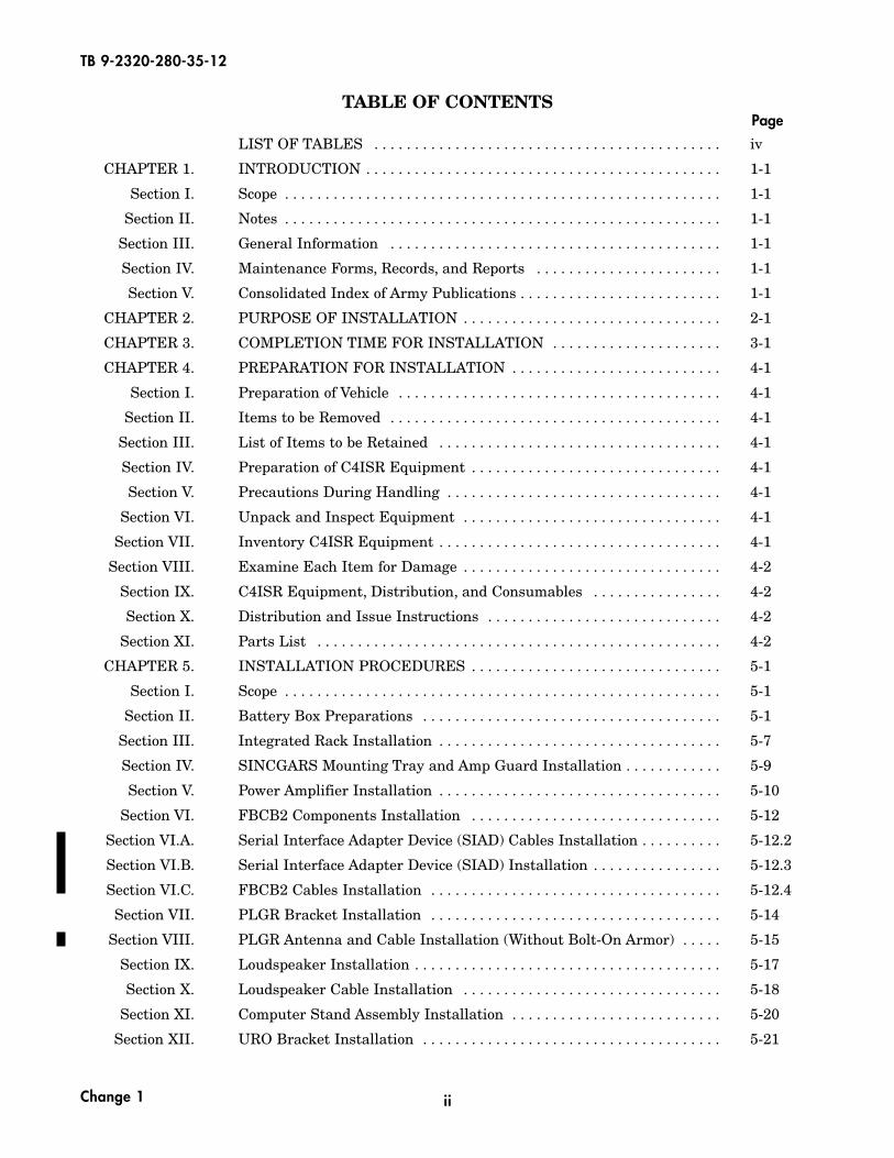
TABLE OF CONTENTSPage
LIST OF TABLES . . . . . . . . . . . . . . . . . . . . . . . . . . . . . . . . . . . . . . . . . . . iv
CHAPTER 1. INTRODUCTION . . . . . . . . . . . . . . . . . . . . . . . . . . . . . . . . . . . . . . . . . . . . 1-1
Section I. Scope . . . . . . . . . . . . . . . . . . . . . . . . . . . . . . . . . . . . . . . . . . . . . . . . . . . . . . 1-1
Section II. Notes . . . . . . . . . . . . . . . . . . . . . . . . . . . . . . . . . . . . . . . . . . . . . . . . . . . . . . 1-1
Section III. General Information . . . . . . . . . . . . . . . . . . . . . . . . . . . . . . . . . . . . . . . . . 1-1
Section IV. Maintenance Forms, Records, and Reports . . . . . . . . . . . . . . . . . . . . . . . 1-1
Section V. Consolidated Index of Army Publications . . . . . . . . . . . . . . . . . . . . . . . . . 1-1
CHAPTER 2. PURPOSE OF INSTALLATION . . . . . . . . . . . . . . . . . . . . . . . . . . . . . . . . 2-1
CHAPTER 3. COMPLETION TIME FOR INSTALLATION . . . . . . . . . . . . . . . . . . . . . 3-1
CHAPTER 4. PREPARATION FOR INSTALLATION . . . . . . . . . . . . . . . . . . . . . . . . . . 4-1
Section I. Preparation of Vehicle . . . . . . . . . . . . . . . . . . . . . . . . . . . . . . . . . . . . . . . . 4-1
Section II. Items to be Removed . . . . . . . . . . . . . . . . . . . . . . . . . . . . . . . . . . . . . . . . . 4-1
Section III. List of Items to be Retained . . . . . . . . . . . . . . . . . . . . . . . . . . . . . . . . . . . 4-1
Section IV. Preparation of C4ISR Equipment . . . . . . . . . . . . . . . . . . . . . . . . . . . . . . . 4-1
Section V. Precautions During Handling . . . . . . . . . . . . . . . . . . . . . . . . . . . . . . . . . . 4-1
Section VI. Unpack and Inspect Equipment . . . . . . . . . . . . . . . . . . . . . . . . . . . . . . . . 4-1
Section VII. Inventory C4ISR Equipment . . . . . . . . . . . . . . . . . . . . . . . . . . . . . . . . . . . 4-1
Section VIII. Examine Each Item for Damage . . . . . . . . . . . . . . . . . . . . . . . . . . . . . . . . 4-2
Section IX. C4ISR Equipment, Distribution, and Consumables . . . . . . . . . . . . . . . . 4-2
Section X. Distribution and Issue Instructions . . . . . . . . . . . . . . . . . . . . . . . . . . . . . 4-2
Section XI. Parts List . . . . . . . . . . . . . . . . . . . . . . . . . . . . . . . . . . . . . . . . . . . . . . . . . . 4-2
CHAPTER 5. INSTALLATION PROCEDURES . . . . . . . . . . . . . . . . . . . . . . . . . . . . . . . 5-1
Section I. Scope . . . . . . . . . . . . . . . . . . . . . . . . . . . . . . . . . . . . . . . . . . . . . . . . . . . . . . 5-1
Section II. Battery Box Preparations . . . . . . . . . . . . . . . . . . . . . . . . . . . . . . . . . . . . . 5-1
Section III. Integrated Rack Installation . . . . . . . . . . . . . . . . . . . . . . . . . . . . . . . . . . . 5-7
Section IV. SINCGARS Mounting Tray and Amp Guard Installation . . . . . . . . . . . . 5-9
Section V. Power Amplifier Installation . . . . . . . . . . . . . . . . . . . . . . . . . . . . . . . . . . . 5-10
Section VI. FBCB2 Components Installation . . . . . . . . . . . . . . . . . . . . . . . . . . . . . . . 5-12
Section VI.A. Serial Interface Adapter Device (SIAD) Cables Installation . . . . . . . . . . 5-12.2
Section VI.B. Serial Interface Adapter Device (SIAD) Installation . . . . . . . . . . . . . . . . 5-12.3
Section VI.C. FBCB2 Cables Installation . . . . . . . . . . . . . . . . . . . . . . . . . . . . . . . . . . . . 5-12.4
Section VII. PLGR Bracket Installation . . . . . . . . . . . . . . . . . . . . . . . . . . . . . . . . . . . . 5-14
Section VIII. PLGR Antenna and Cable Installation (Without Bolt-On Armor) . . . . . 5-15
Section IX. Loudspeaker Installation . . . . . . . . . . . . . . . . . . . . . . . . . . . . . . . . . . . . . . 5-17
Section X. Loudspeaker Cable Installation . . . . . . . . . . . . . . . . . . . . . . . . . . . . . . . . 5-18
Section XI. Computer Stand Assembly Installation . . . . . . . . . . . . . . . . . . . . . . . . . . 5-20
Section XII. URO Bracket Installation . . . . . . . . . . . . . . . . . . . . . . . . . . . . . . . . . . . . . 5-21
Change 1

TB 9-2320-280-35-12
iii
TABLE OF CONTENTS (Contd)
Page
Section XIII. Master Kill Switch Box Installation . . . . . . . . . . . . . . . . . . . . . . . . . . . . . 5-22
Section XIV. Computer Stand Cable Installation . . . . . . . . . . . . . . . . . . . . . . . . . . . . . 5-23
Section XV. Multi-Net Rack Installation . . . . . . . . . . . . . . . . . . . . . . . . . . . . . . . . . . . 5-25
Section XVI. EPLRS Dual Mount Installation . . . . . . . . . . . . . . . . . . . . . . . . . . . . . . . . 5-30
Section XVII. Printer Installation . . . . . . . . . . . . . . . . . . . . . . . . . . . . . . . . . . . . . . . . . . 5-31
Section XVIII. KOK-13 Crypto Generator Installation . . . . . . . . . . . . . . . . . . . . . . . . . . 5-33
Section XIX. Battery Alarm Box Installation . . . . . . . . . . . . . . . . . . . . . . . . . . . . . . . . . 5-34
Section XX. Inverter Installation . . . . . . . . . . . . . . . . . . . . . . . . . . . . . . . . . . . . . . . . . 5-35
Section XXI. Rear Battery Box Installation . . . . . . . . . . . . . . . . . . . . . . . . . . . . . . . . . . 5-37
Section XXII. AC Distribution Box Installation . . . . . . . . . . . . . . . . . . . . . . . . . . . . . . . 5-38
Section XXIII. AC Output Selection Box Installation . . . . . . . . . . . . . . . . . . . . . . . . . . . 5-39
Section XXIV. DC Charger Installation . . . . . . . . . . . . . . . . . . . . . . . . . . . . . . . . . . . . . . 5-40
Section XXV. External Power Reception Box Installation . . . . . . . . . . . . . . . . . . . . . . . 5-42
Section XXVI. EPLRS Antenna Installation . . . . . . . . . . . . . . . . . . . . . . . . . . . . . . . . . . . 5-44
Section XXVII. Left-Side SINCGARS Antenna Mount Installation . . . . . . . . . . . . . . . . . 5-45
Section XXVIII. Right-Side SINCGARS Antenna Mount Installation . . . . . . . . . . . . . . . 5-51
Section XXIX. Vehicle Ground Installation . . . . . . . . . . . . . . . . . . . . . . . . . . . . . . . . . . . . 5-55
Section XXX. QEAM: Antennas and Brackets Installation . . . . . . . . . . . . . . . . . . . . . . 5-56
Section XXXI. SINCGARS Antenna Cable Installation . . . . . . . . . . . . . . . . . . . . . . . . . . 5-60
Section XXXII. PLGR Power Cable Installation . . . . . . . . . . . . . . . . . . . . . . . . . . . . . . . . 5-64
Section XXXIII. Left-Side EPLRS Antenna Cable Installation . . . . . . . . . . . . . . . . . . . . . 5-65
Section XXXIV. Right-Side EPLRS Antenna Cable Installation . . . . . . . . . . . . . . . . . . . . 5-69
Section XXXV. Computer Stand Tunnel Cable Installation . . . . . . . . . . . . . . . . . . . . . . . 5-72
Section XXXVI. Master Kill Switch Cable Installation . . . . . . . . . . . . . . . . . . . . . . . . . . . 5-75
Section XXXVII. Remote Curbside Separator Cable Installation . . . . . . . . . . . . . . . . . . . 5-76
Section XXXVIII. External Power Reception Box Cable Installation . . . . . . . . . . . . . . . . . . 5-79
Section XXXIX. DC Charger Cable Installation . . . . . . . . . . . . . . . . . . . . . . . . . . . . . . . . . 5-82
Section XL. AC Distribution Box Cable Installation . . . . . . . . . . . . . . . . . . . . . . . . . . 5-84
Section XLI. AC Output Selection Box Cable Installation . . . . . . . . . . . . . . . . . . . . . . 5-85
Section XLII. Inverter Cable Installation . . . . . . . . . . . . . . . . . . . . . . . . . . . . . . . . . . . . 5-86
Section XLIII. Rear Battery Cable Installation . . . . . . . . . . . . . . . . . . . . . . . . . . . . . . . . 5-87
Section XLIV. Multi-Net Rack Rear Cable Installation . . . . . . . . . . . . . . . . . . . . . . . . . . 5-88
Section XLV. Driver-Side Multi-Net Rack Cable Installation . . . . . . . . . . . . . . . . . . . . 5-90
Section XLVI. Passenger-Side Multi-Net Rack Cable Installation . . . . . . . . . . . . . . . . . 5-94
Change 1

TB 9-2320-280-35-12
iv
Page
Section XLVII. C4ISR Power Cable Installation . . . . . . . . . . . . . . . . . . . . . . . . . . . . . . . . 5-96
Section XLVIII. Windshield Armor Modification . . . . . . . . . . . . . . . . . . . . . . . . . . . . . . . . 5-107
Section XLIX. Armor and Antenna Installation(With Bolt-On Armor) . . . . . . . . . . . . . . . . . . . . . . . . . . . . . . . . . . . . . . . . 5-110
Section L. Antenna Cable Installation . . . . . . . . . . . . . . . . . . . . . . . . . . . . . . . . . . . . 5-114
LIST OF TABLES
Table Title Page
4-1. Kits Parts List for Installation of C4ISR Equipment . . . . . . . . . . . . . . . . . . . 4-3
4-2. Non-Kit Parts List for Installation of C4ISR Equipment . . . . . . . . . . . . . . . 4-5
APPENDIX
Appendix Title Page
Appendix Cable Schematic . . . . . . . . . . . . . . . . . . . . . . . . . . . . . . . . . . . . . . . . . . . . . . . . A-1
Change 1
TABLE OF CONTENTS (Contd)
1-1/(1-2 blank)
CHAPTER 1
INTRODUCTION
Section I. SCOPE1-1. This technical bulletin provides installation instructions for Command, Control, Communications,
Computers, Intelligence, Surveillance, and Reconnaissance (C4ISR) equipment. The C4ISR equipmentshall be installed in the following vehicles:
Truck, Utility, 2/4-Door: Heavy Variant, 1-1/4 Ton, 4x4, M1097A2
1-2. The information contained in this technical bulletin is the official authorization to perform theinstallation of the C4ISR equipment at the direct support maintenance level through contractmaintenance teams.
Section II. NOTES2-1. This technical bulletin is not an authorization for requisition or turn-in of vehicles.
2-2. This technical bulletin does not establish quantity or types of vehicles assigned to using units.
Section III. GENERAL INFORMATION3-1. Included in the C4ISR equipment are:
a. Single Channel Ground and Airborne Radio System (SINCGARS), AN/VRC-92F
b. Force XXI Battle Command, Brigade-and-Below (FBCB2), AN/UYK-128 (V)4
c. Precision Lightweight Global Positioning System Receiver (PLGR), AN/PSN-11
d. Enhanced Position Location Reporting System (EPLRS), AN/VSQ-2 (V)
e. Remote Rekey Device, KOK-13
f. Quick-Erect Antenna Mount (QEAM), AB-1386/U
g. Network Manager and Printer
h. Supplementary Batteries
3-2. The C4ISR equipment becomes operable when all the components are installed in the vehicle andcorrect power is supplied.
Section IV. MAINTENANCE FORMS, RECORDS, AND REPORTSUse the following to report any discrepancies:
a. Reports of Maintenance and Unsatisfactory Equipment. See chapter 4, sections VI through VIII for information.
b. Reports of Packaging and Handling Deficiencies. See chapter 4, sections VI through VIII for information.
Section V. CONSOLIDATED INDEX OF ARMY PUBLICATIONSRefer to the latest issue of DA PAM 25-30 to determine whether there are new changes or additionalpublications pertaining to the C4ISR equipment.
TB 9-2320-280-35-12


2-1/(2-2 blank)
CHAPTER 2
PURPOSE OF INSTALLATION
The purpose of installing the C4ISR equipment is to provide the primary means of integrating commandand control capability.
TB 9-2320-280-35-12


TB 9-2320-280-35-12
3-1/(3-2 blank)
CHAPTER 3
COMPLETION TIME FOR INSTALLATION
A total of 20 man hours are required for two personnel to install the C4ISR equipment. Typical vehicledowntime is 12 hours.


CHAPTER 4
PREPARATION FOR INSTALLATION
Section I. PREPARATION OF VEHICLEEnsure that the site includes adequate lighting and a power source when drilling is required. Inspect thevehicle for damage that could affect installation. Have any such damage repaired before installing theC4ISR equipment.
Section II. ITEMS TO BE REMOVED2-1. Remove batteries. (Refer to TM 9-2320-280-20.)
2-2. Remove left- and right-hand rear door, as applicable. (Refer to TM 9-2320-280-20.)
2-3. Remove center tunnel insulation, as applicable. (Refer to TM 9-2320-280-20.)
2-4. Remove standard radio rack. (Refer to TM 9-2320-280-20.)
Section III. LIST OF ITEMS TO BE RETAINED3-1. Batteries.
3-2. Left- and right-hand rear cab enclosure panel (if applicable).
3-3. Left- and right-hand rear fixed door (if applicable).
Section IV. PREPARATION OF C4ISR EQUIPMENTUnpack, inspect, and check inventory.
Section V. PRECAUTIONS DURING HANDLINGObserve the following precautions to prevent equipment damage.
a. Keep dust covers in place on connectors.
b. Do not disassemble or modify parts in the C4ISR equipment unless authorized to do so.
c. Keep mounting hardware covered and protected until needed.
Section VI. UNPACK AND INSPECT EQUIPMENT6-1. Unpack and inspect packaging for evidence of damage.
6-2. Report any shipping damage on SF 364 Report of Discrepancy (ROD) as prescribed in AR 735-11-2/DLAR 4140.55/NAVMATINST 4355.73A/AFR 400-64/MCO 4430.F.
Section VII. INVENTORY C4ISR EQUIPMENTIf any item is missing, fill out and forward Transportation Discrepancy Report (TDR) (SF 361) as describedin AR 55-38/NAVSUPINST 4610.33C/AFR 75-18/MCO P4610.19D/DLAR 450015.
4-1
TB 9-2320-280-35-12

Section VIII. EXAMINE EACH ITEM FOR DAMAGEIf any item is damaged, fill out and forward SF 364 Report of Discrepancy (ROD) as prescribed inAR 735-11-2/DLAR 4140.55/NAVMATINST 4355.73A/AFR 400-64/MCO 4430.F. All damages should bereported as prescribed by DA PAM 738-750, as contained in the Maintenance Management Update.
Section IX. C4ISR EQUIPMENT, DISTRIBUTION, AND CONSUMABLES9-1. Items supplied in C4ISR equipment and/or required for installation.
9-2. Use table 4-1 to identify and inventory C4ISR equipment parts required to perform installation.Refer to table 4-2 to identify additional materials required to install C4ISR equipment.
Section X. DISTRIBUTION AND ISSUE INSTRUCTIONS10-1. U.S. Forces: Do not requisition C4ISR equipment. It will be shipped automatically.
10-2. U.S. Army Depots: Requisition C4ISR equipment through supply channels.
10-3. Multiservice: Instructions shall be included for multiservice modifications.
10-4. MAP/MAS countries: Instructions shall be provided for MAP/MAS countries.
Section XI. PARTS LIST
KITS REQUIRED FOR THIS INSTALLATION:
NOTE• Not all material in kits is required for this installation. Material not
used during installation will be returned to stock for disposition inaccordance with AR 725-50.
• If maintenance is to be performed on a vehicle with an existing kit,do not order entire kit for necessary reinstallation.
SINCGARS:
(A): MK-2326(B): MK-2327(C): MK-2328
PLGR:
(D): 57K4400
EPLRS:
(E): MK-2467A/VSQ-1(F): MK-2520/VSQ-1
FBCB2:
(G): No kits available
4-2
TB 9-2320-280-35-12
REMOTE REKEY DEVICE:
(H): No kits available
QEAM:
(I): No kits available
NETWORK MANAGER AND PRINTER:
(J): No kits available
SUPPLEMENTAL BATTERIES:
(K): No kits available

MATERIAL REQUIRED FROM KITS:
Table 4-1. Kit Parts List for Installation of C4ISR Equipment.ITEM NOMENCLATURE PART NUMBER NATIONAL/NATO KIT QTY.NO. STOCK NUMBER
1. Bracket, Antenna A3014546-1 5340-01-391-2742 (A),(B),(C) 22. Bracket, Double-Angle A3046237 5340-01-262-9566 (B),(C) 23. Cable Assembly, Antenna A3014031-17 5995-01-225-1660 (B),(C) 14. Cable Assembly,
Antenna, EPLRS SM-C-911480 5995-01-167-1269 (E),(F) 25. Cable Assembly,
Power, Electrical A3014040-9 5995-01-300-9324 (B),(C) 16. Cable Assembly, Power, EPLRS A3004939 5995-01-198-0538 (E),(F) 27. Cable Assembly,
Radio Frequency A3014031-8 5995-01-219-7035 (A),(B),(C) 18. Cable Assembly,
Radio Frequency A3014032-3 5995-01-219-7025 (A),(B),(C) 19. Cable Assembly,
Special Purpose A3014038-12 5995-01-259-9283 (B),(C) 110. Clamp, Loop MS21333-67 5340-00-079-7837 (D) 111. Clamp, Loop MS21333-71 5340-00-057-2904 (A),(B),(C) 1612. Clamp, Loop MS21333-75 5340-00-050-2740 (A),(B),(C) 1113. Clamp, Loop MS21333-96 5340-00-088-1255 (C),(D) 214. Clamp, Loop MS21333-102 5340-00-984-8540 (B) 215. Fiber Rope Assembly,
Single Leg A3167672-1 4020-01-341-8795 (A),(B),(C),(F) 216. Gasket A3013655-1 5330-01-205-2864 (A),(B),(C) 417. Grommet, Nonmetallic MS21266-4N 5325-00-923-9512 (B),(C) 218. Grommet MS35489-31 5325-00-174-9336 (D) 119. Handset H-250/U 5965-00-043-3463 (A),(B),(C),(F) 220. Insert 12446871-2 5310-01-411-3422 (C) 321. Loudspeaker A3014065-1 5965-01-222-1420 (A),(B),(C) 222. Mounting Base,
Electrical Equipment A3013367-1 5975-01-188-8873 (A),(B),(C),(F) 123. Mounting Base,
Electrical Equipment A3014053-1 5975-01-235-1962 (B),(C) 124. Nut MS35650-302 5310-00-934-9751 (A),(B),(C),(E),(F) 2325. Nut MS51967-2 5310-00-761-6882 (A),(B),(C),(E),(F) 3626. Nut MS51967-5 5310-00-880-7744 (F) 4027. Nut MS51967-6 5310-00-931-8167 (E),(F) 828. Nut MS51967-8 5310-00-732-0558 (E),(F) 229. Nut MS51968-5 5310-00-880-7746 (A),(B),(C),(F) 230. Nut 9419143 5310-01-148-0240 (C) 1131. Nut MS35690-610 5310-00-655-6457 (F) 2632. Nut, Strip A3014064-1 N/A (B),(C) 133. Plate, Backing A3046222 5975-01-264-1720 (F) 234. Plate, Metal A3103740 5340-01-302-0068 (F) 2
4-3
TB 9-2320-280-35-12
Change 1
35. Plate, Metal A3103784 N/A (F) 236. Plate, Mounting A3014550-1 N/A (A),(B),(C) 237. Screw, Cap B1821BH025C100N 5305-00-225-3843 (C) 1738. Screw, Cap B1821BH025C125N 5305-00-068-0509 (C),(D) 839. Screw, Cap B1821BH025C175N 5305-00-071-2510 (D) 140. Screw, Cap MS35207-261 5305-00-990-6444 (D) 141. Screw, Cap MS35307-365 5305-00-847-1159 (A),(B),(C),(F) 1142. Screw, Cap MS90725-6 5305-00-068-0502 (A),(B),(F) 1943. Screw, Cap MS90725-8 5305-00-225-3839 (A),(B),(C),(F) 3944. Screw, Cap MS90725-10 5305-00-068-0509 (F) 645. Screw, Cap MS90726-36 5305-00-225-9091 (B),(C) 2246. Screw, Cap MS90725-30 5306-00-225-8495 (F) 847. Screw, Cap MS90725-62 5305-00-269-3213 (F) 848. Screw, Cap MS90725-64 5305-00-325-8387 (F) 1849. Screw, Machine MS35224-65 5310-00-543-5743 (F) 150. Screw, Machine MS35206-217 5305-00-889-2999 (E),(F) 851. Screw, Machine MS35190-291 5305-00-958-5247 (B) 252. Screw, Machine MS35206-263 5305-00-984-6210 (C) 453. Screw, Machine MS35207-261 5305-00-990-6444 (C) 154. Screw, Machine MS35207-263 5305-00-989-7434 (E),(F) 1255. Screw, Machine MS35207-267 5305-00-993-1851 (F) 1256. Screw, Self-Tapping 9421073 5305-01-162-8512 (C) 1457. Screw, Self-Tapping 9416639 5305-01-197-2320 (D) 158. Strap, Tie MS3367-1-0 5975-00-984-6582 (C),(D) 359. Support, Antenna A3103782 5985-01-312-3028 (F) 260. Washer MS15795-814 5310-00-773-7618 (F) 2661. Washer MS27183-10 5310-00-809-4058 (B),(C),(F) 4162. Washer MS27183-12 5310-00-081-4219 (B),(C),(F) 3063. Washer MS27183-18 5310-00-809-5998 (B),(C),(F) 564. Washer 2436161 5310-01-102-3270 (C),(D) 2965. Washer MS27183-8 5310-00-809-8546 (E),(F) 3466. Washer, Lock MS35333-76 5310-00-180-0277 (C) 667. Washer, Lock MS35338-43 5310-00-045-3296 (A),(B),(C),(D),(E),(F) 2168. Washer, Lock MS35338-44 5310-00-582-5965 (A),(B),(C),(D),(F) 4369. Washer, Lock MS35338-45 5310-00-407-9566 (B),(C) 2470. Washer, Lock MS35338-46 5310-00-637-9541 (B),(C),(E),(F) 1071. Washer, Lock MS35338-48 5310-00-584-5272 (B),(C) 272. Washer, Lock MS35338-141 5310-00-984-7042 (F) 2673. Washer, Lock MS45904-60 5310-00-080-9786 (E) 1774. Washer, Lock MS45904-68 5310-00-889-2528 (A),(B),(C) 5175. Washer, Lock MS45904-72 5310-00-889-2527 (A),(B),(C),(E),(F) 68
4-4
TB 9-2320-280-35-12
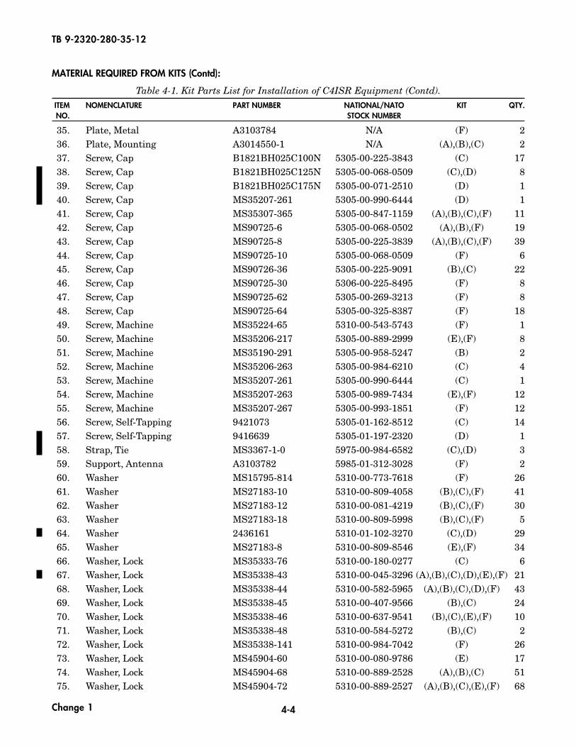
MATERIAL REQUIRED FROM KITS (Contd):
Table 4-1. Kit Parts List for Installation of C4ISR Equipment (Contd).ITEM NOMENCLATURE PART NUMBER NATIONAL/NATO KIT QTY.NO. STOCK NUMBER
Change 1
4-5
TB 9-2320-280-35-12
1. AC Distribution Box A3265676 N/A 12. AC Output Selection Box A3265686 N/A 13. Antenna A3005031 5820-01-183-9462 24. Antenna AS-3900/VRC A3017889-2 5985-01-308-8988 25. Antenna, Element (lower) A3018230-1 5985-01-201-1498 26. Antenna, Element (upper) A3017901-2 5985-01-306-4622 27. Antenna, PLGR AT575-030 5985-01-375-4660 18. Assembly, Display Lock 872843-01 N/A 19. Base, Lower A3265624 N/A 1
10. Base, Upper A3265626 N/A 111. Battery 8A27M 6140-01-524-2650 112. Battery Alarm Box A3265665 6350-01-523-7612 113. Battery Box A3265709 N/A 114. Battery Tray A3265708 N/A 115. Bolt MS35751-18 5306-00-108-9988 416. Bolt, Carriage 93548A652 5306-01-527-3738 217. Bracket, PLGR 986-0645-001 5975-01-375-1302 118. Bracket, PLGR Antenna A3210768 5985-01-477-9907 119. Bracket, User Readout (URO) A3006206-2 5340-01-386-7841 220. Cable Assembly, Battery Alarm Box A3265596 N/A 121. Cable Assembly, Battery Negative A3265734 N/A 122. Cable Assembly, Battery Positive A3265733 N/A 123. Cable Assembly, Ethernet A3265597 N/A 124. Cable Assembly, Ethernet A3265725 N/A 125. Cable Assembly, Inverter Negative A3265692 N/A 126. Cable Assembly, Inverter Positive A3265730 N/A 127. Cable Assembly, KOK-13 Power A3265651 6150-01-522-4040 128. Cable Assembly,
Output Power Selection Box A3265726 N/A 129. Cable Assembly, PCMCIA A3265957 5995-01-522-4436 130. Cable Assembly, Power, PLGR 9728558-10 6150-01-375-8661 131. Cable Assembly, EPLRS Antenna A3265727 N/A 132. Cable Assembly, External Power A3265729 N/A 133. Cable Assembly, Power A3014039-2 5995-01-219-1843 134. Cable Assembly, Power A3279383-3 5995-01-453-9171 135. Cable Assembly, Power 426-0141-050 6150-01-375-8662 136. Cable Assembly, Printer AC Power A3265673 6150-01-522-4044 137. Cable Assembly, Prosine Inverter Output A3265674 6150-01-522-5603 138. Cable Assembly, Special Purpose A3014038-3 5995-01-219-4704 139. Cable Assembly, Special Purpose A3014037-4 5995-01-335-7863 1
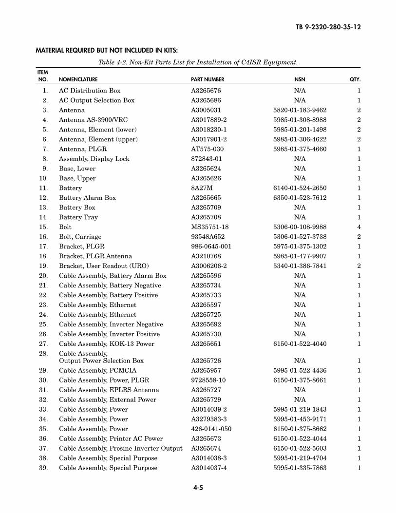
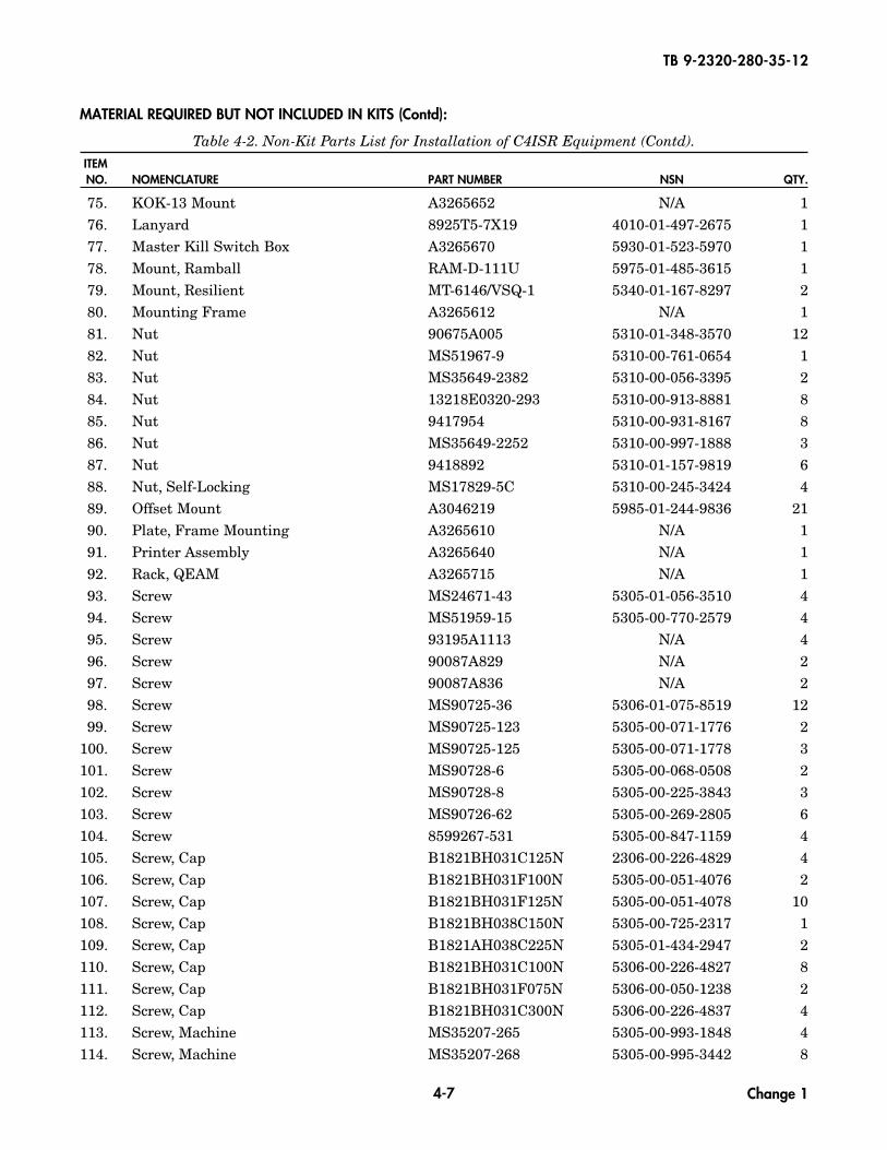
MATERIAL REQUIRED BUT NOT INCLUDED IN KITS:
Table 4-2. Non-Kit Parts List for Installation of C4ISR Equipment.ITEMNO. NOMENCLATURE PART NUMBER NSN QTY.
4-6
TB 9-2320-280-35-12
40. Cable Assembly, Special Purpose A3005328 5995-01-375-2439 241. Cable Block 7565K51 N/A 142. Cable Carrier 55835K42 N/A 143. Cable Carrier 55835K44 N/A 1
43.1 Cable, W1 866003-3 5995-01-478-4908 143.2 Cable, W2 881327-1 5995-01-478-4876 143.3 Cable, W3N 881336-1 5995-01-478-4913 143.4 Cable, W3P 881335-1 5995-01-478-4891 144. Center Support A3265621 N/A 145. Channel Hold Down A3265712 5340-01-527-4884 146. Clamp, Loop MS21333-69 5340-00-764-7051 2747. Clamp, Loop MS21333-65 5340-00-905-0790 748. Clamp, Loop 3225T43 N/A 549. Clamp, Loop 3225T44 N/A 250. Clamp, Loop 3225T46 N/A 1451. Clamp, Loop 3225T48 N/A 1252. Clamp, Subassembly A3209994 5340-01-424-1516 453. Computer Stand Assembly A3265632 N/A 154. CPU (Central Processing Unit) 881292-1 7021-01-474-3793 155. DC Charger 93-WP40-A 6130-01-526-2770 156. DC Charger Guard A3265713 N/A 157. DC-DC Adapter PA1540-647 6130-01-524-2337 158. Decal 861868-2 N/A 1
58.1 Device, Serial Interface Adapter 881331-1 4920-01-478-3722 159. Display 881293-1 7025-01-475-0229 160. External Power Reception Box A3265660 6110-01-523-7686 161. Fender Washer 9109A111 N/A 1362. Fender Washer 90313A112 5310-01-527-4877 463. Fender Washer 6001001 5310-01-498-7962 464. Grommet, Nonmetallic MS21266-4N 5325-00-923-9512 A/R65. Grommet, Nonmetallic 12338098 5325-01-308-5424 266. Guard, Amp 872842-1 5935-01-487-2172 167. Insert 12446871-2 5310-01-411-3422 1868. Insert ALS4-420-165 5310-01-411-3422 1469. Inverter 806-1050 6130-01-527-4041 170. Inverter Front Cover Plate A3265693 N/A 171. Inverter Housing Support A3265690 N/A 172. Inverter Top Plate A3265691 N/A 173. Isolation Kit, CPU 872826-2 5340-01-481-5741 174. Isolation Kit, Display 872870-1 5340-01-481-5757 1
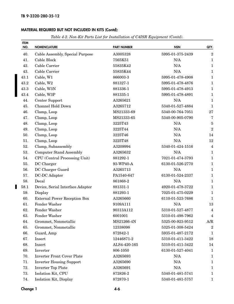
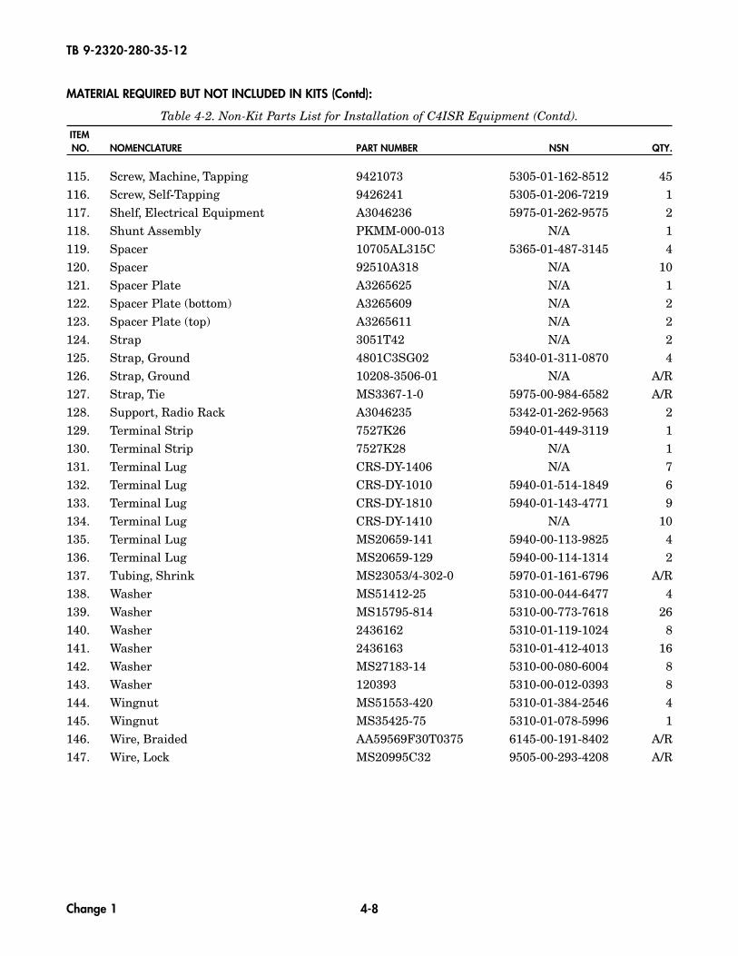
MATERIAL REQUIRED BUT NOT INCLUDED IN KITS (Contd):
Table 4-2. Non-Kit Parts List for Installation of C4ISR Equipment (Contd).ITEMNO. NOMENCLATURE PART NUMBER NSN QTY.
Change 1
4-7
TB 9-2320-280-35-12
75. KOK-13 Mount A3265652 N/A 176. Lanyard 8925T5-7X19 4010-01-497-2675 177. Master Kill Switch Box A3265670 5930-01-523-5970 178. Mount, Ramball RAM-D-111U 5975-01-485-3615 179. Mount, Resilient MT-6146/VSQ-1 5340-01-167-8297 280. Mounting Frame A3265612 N/A 181. Nut 90675A005 5310-01-348-3570 1282. Nut MS51967-9 5310-00-761-0654 183. Nut MS35649-2382 5310-00-056-3395 284. Nut 13218E0320-293 5310-00-913-8881 885. Nut 9417954 5310-00-931-8167 886. Nut MS35649-2252 5310-00-997-1888 387. Nut 9418892 5310-01-157-9819 688. Nut, Self-Locking MS17829-5C 5310-00-245-3424 489. Offset Mount A3046219 5985-01-244-9836 2190. Plate, Frame Mounting A3265610 N/A 191. Printer Assembly A3265640 N/A 192. Rack, QEAM A3265715 N/A 193. Screw MS24671-43 5305-01-056-3510 494. Screw MS51959-15 5305-00-770-2579 495. Screw 93195A1113 N/A 496. Screw 90087A829 N/A 297. Screw 90087A836 N/A 298. Screw MS90725-36 5306-01-075-8519 1299. Screw MS90725-123 5305-00-071-1776 2
100. Screw MS90725-125 5305-00-071-1778 3101. Screw MS90728-6 5305-00-068-0508 2102. Screw MS90728-8 5305-00-225-3843 3103. Screw MS90726-62 5305-00-269-2805 6104. Screw 8599267-531 5305-00-847-1159 4105. Screw, Cap B1821BH031C125N 2306-00-226-4829 4106. Screw, Cap B1821BH031F100N 5305-00-051-4076 2107. Screw, Cap B1821BH031F125N 5305-00-051-4078 10108. Screw, Cap B1821BH038C150N 5305-00-725-2317 1109. Screw, Cap B1821AH038C225N 5305-01-434-2947 2110. Screw, Cap B1821BH031C100N 5306-00-226-4827 8111. Screw, Cap B1821BH031F075N 5306-00-050-1238 2112. Screw, Cap B1821BH031C300N 5306-00-226-4837 4113. Screw, Machine MS35207-265 5305-00-993-1848 4114. Screw, Machine MS35207-268 5305-00-995-3442 8
MATERIAL REQUIRED BUT NOT INCLUDED IN KITS (Contd):
Table 4-2. Non-Kit Parts List for Installation of C4ISR Equipment (Contd).ITEMNO. NOMENCLATURE PART NUMBER NSN QTY.
Change 1
4-8
TB 9-2320-280-35-12
115. Screw, Machine, Tapping 9421073 5305-01-162-8512 45116. Screw, Self-Tapping 9426241 5305-01-206-7219 1117. Shelf, Electrical Equipment A3046236 5975-01-262-9575 2118. Shunt Assembly PKMM-000-013 N/A 1119. Spacer 10705AL315C 5365-01-487-3145 4120. Spacer 92510A318 N/A 10121. Spacer Plate A3265625 N/A 1122. Spacer Plate (bottom) A3265609 N/A 2123. Spacer Plate (top) A3265611 N/A 2124. Strap 3051T42 N/A 2125. Strap, Ground 4801C3SG02 5340-01-311-0870 4126. Strap, Ground 10208-3506-01 N/A A/R127. Strap, Tie MS3367-1-0 5975-00-984-6582 A/R128. Support, Radio Rack A3046235 5342-01-262-9563 2129. Terminal Strip 7527K26 5940-01-449-3119 1130. Terminal Strip 7527K28 N/A 1131. Terminal Lug CRS-DY-1406 N/A 7132. Terminal Lug CRS-DY-1010 5940-01-514-1849 6133. Terminal Lug CRS-DY-1810 5940-01-143-4771 9134. Terminal Lug CRS-DY-1410 N/A 10135. Terminal Lug MS20659-141 5940-00-113-9825 4136. Terminal Lug MS20659-129 5940-00-114-1314 2137. Tubing, Shrink MS23053/4-302-0 5970-01-161-6796 A/R138. Washer MS51412-25 5310-00-044-6477 4139. Washer MS15795-814 5310-00-773-7618 26140. Washer 2436162 5310-01-119-1024 8141. Washer 2436163 5310-01-412-4013 16142. Washer MS27183-14 5310-00-080-6004 8143. Washer 120393 5310-00-012-0393 8144. Wingnut MS51553-420 5310-01-384-2546 4145. Wingnut MS35425-75 5310-01-078-5996 1146. Wire, Braided AA59569F30T0375 6145-00-191-8402 A/R147. Wire, Lock MS20995C32 9505-00-293-4208 A/R
MATERIAL REQUIRED BUT NOT INCLUDED IN KITS (Contd):
Table 4-2. Non-Kit Parts List for Installation of C4ISR Equipment (Contd).ITEMNO. NOMENCLATURE PART NUMBER NSN QTY.
Change 1
TB 9-2320-280-35-12
5-1
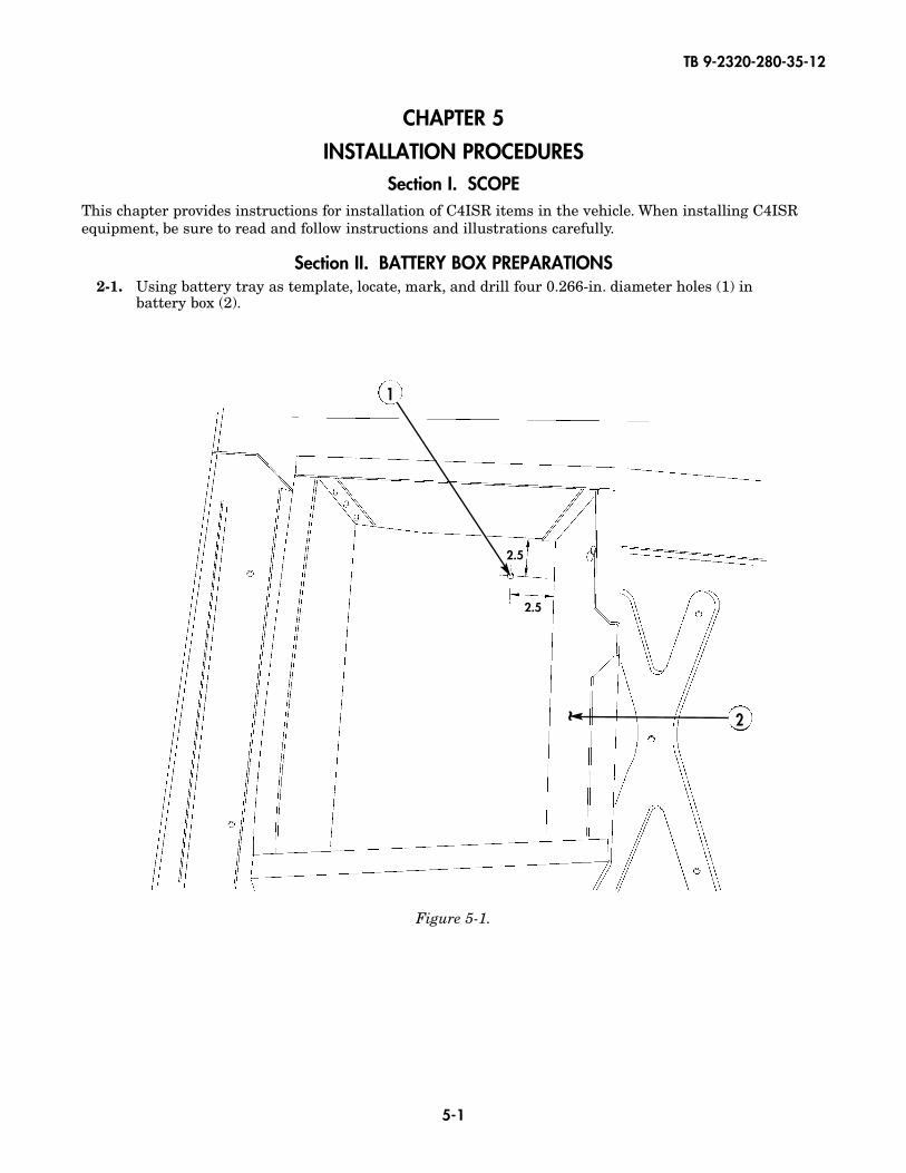
Figure 5-1.
1
2~2.5
2.5
CHAPTER 5
INSTALLATION PROCEDURESSection I. SCOPE
This chapter provides instructions for installation of C4ISR items in the vehicle. When installing C4ISRequipment, be sure to read and follow instructions and illustrations carefully.
Section II. BATTERY BOX PREPARATIONS2-1. Using battery tray as template, locate, mark, and drill four 0.266-in. diameter holes (1) in
battery box (2).
TB 9-2320-280-35-12
5-2
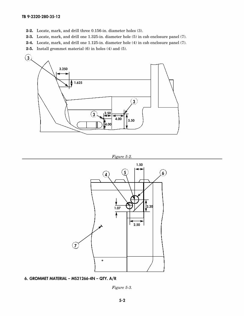
2-2. Locate, mark, and drill three 0.156-in. diameter holes (3).2-3. Locate, mark, and drill one 1.325-in. diameter hole (5) in cab enclosure panel (7).2-4. Locate, mark, and drill one 1.125-in. diameter hole (4) in cab enclosure panel (7).2-5. Install grommet material (6) in holes (4) and (5).
3.250
1.625
2.50
4.00
4.00 5.50
3
3
4 5 6
3
Figure 5-2.
Figure 5-3.
1.50
2.20
2.50
1.07
6. GROMMET MATERIAL – MS21266-4N – QTY. A/R
7
~
TB 9-2320-280-35-12
5-3
Figure 5-4.
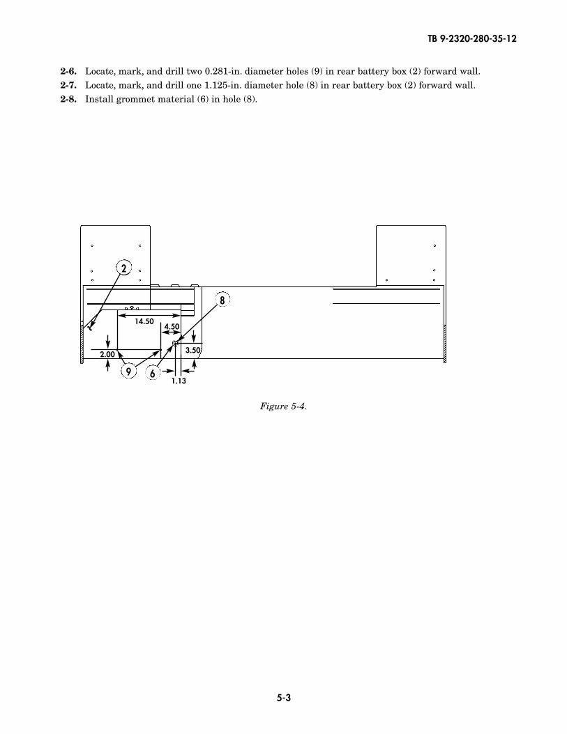
2-6. Locate, mark, and drill two 0.281-in. diameter holes (9) in rear battery box (2) forward wall.2-7. Locate, mark, and drill one 1.125-in. diameter hole (8) in rear battery box (2) forward wall.2-8. Install grommet material (6) in hole (8).
8
6
14.504.50
3.50
1.13
2.00
9
2
~
TB 9-2320-280-35-12
5-4
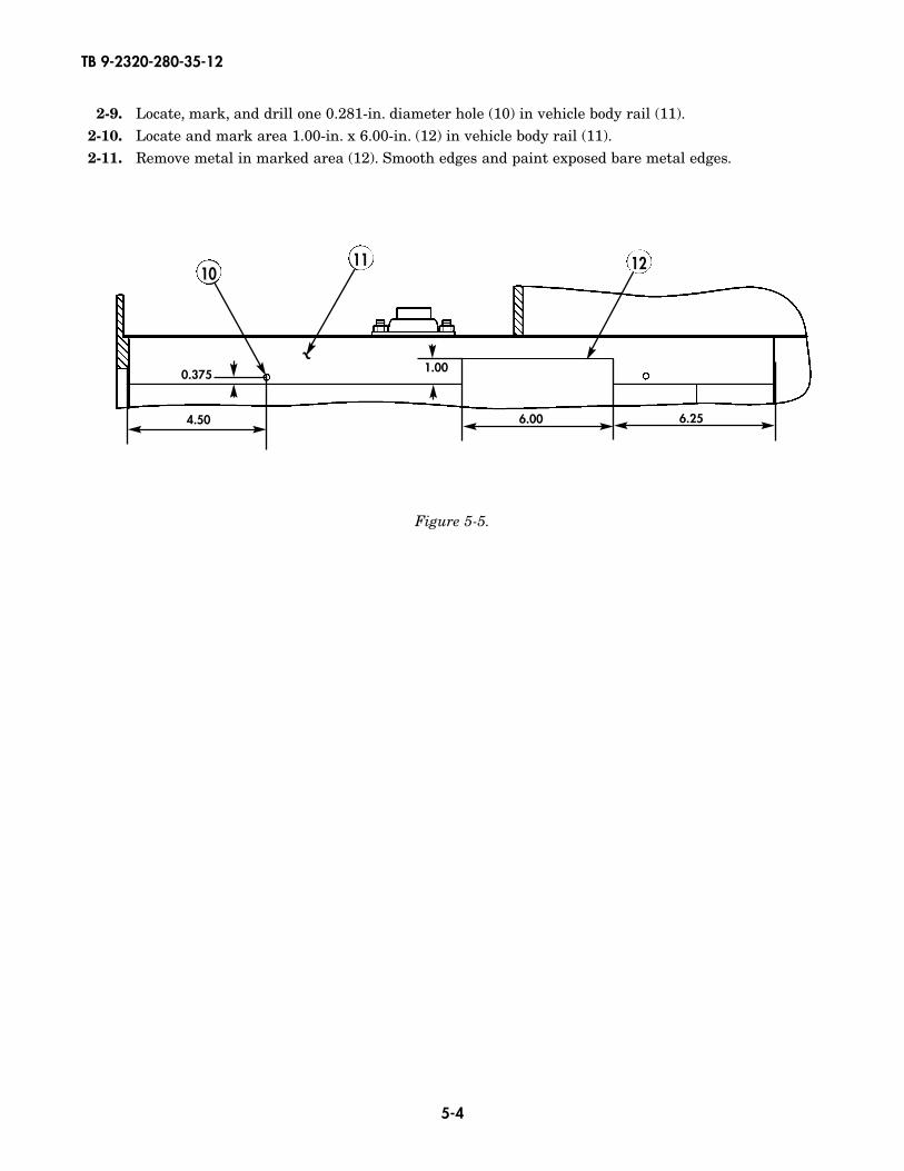
2-9. Locate, mark, and drill one 0.281-in. diameter hole (10) in vehicle body rail (11).2-10. Locate and mark area 1.00-in. x 6.00-in. (12) in vehicle body rail (11).2-11. Remove metal in marked area (12). Smooth edges and paint exposed bare metal edges.
1012
4.50
0.375 1.00
6.00 6.25
11
~
Figure 5-5.

TB 9-2320-280-35-12
5-5
Figure 5-6.
2-12. Using terminal strips (16) and (13) as templates locate, mark, and drill eight 0.201-in. diameter holes (20) in battery box (2) rear wall.
2-13. Secure one 8-position terminal strip (13) and one 6-position terminal strip (16) to battery box (2) rear wall with eight bolts (14), washers (15), lockwashers (17), and nuts (18).
2-14. Using shunt assembly (19) as template, locate, mark, and drill two .201-in. diameter holes (21) inbattery box (2) rear wall.
2-15. Secure shunt assembly (19) to battery box (2) rear wall with two bolts (14), two washers (15),two lockwashers (17), and two nuts (18).
14
1413
2
15
15
20
2119
18
17
1617
18
1.66
1.1252.25
1.004.25
1.66
~
13. TERMINAL STRIP (8-POLE) – 7527K28 – QTY. 114. SCREW – MS35207-267 – QTY. 1015. WASHER – MS27183-8 – QTY. 1016. TERMINAL STRIP (6-POLE) – 7527K26 – QTY. 117. LOCKWASHER – MS45904-60 – QTY. 1018. NUT – MS35650-302 – QTY. 1019. SHUNT ASSEMBLY – PKMM-000-013 – QTY. 1
TB 9-2320-280-35-12
5-6
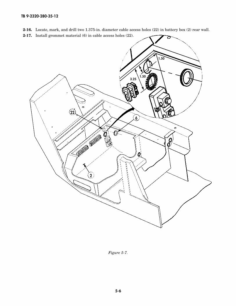
2-16. Locate, mark, and drill two 1.375-in. diameter cable access holes (22) in battery box (2) rear wall.2-17. Install grommet material (6) in cable access holes (22).
3.251.50
1.50
226
2
~
Figure 5-7.
TB 9-2320-280-35-12
5-7
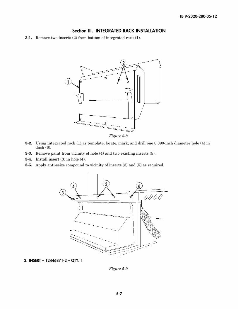
Section III. INTEGRATED RACK INSTALLATION3-1. Remove two inserts (2) from bottom of integrated rack (1).
3-2. Using integrated rack (1) as template, locate, mark, and drill one 0.390-inch diameter hole (4) in dash (6).
3-3. Remove paint from vicinity of hole (4) and two existing inserts (5).3-4. Install insert (3) in hole (4).3-5. Apply anti-seize compound to vicinity of inserts (3) and (5) as required.
Figure 5-8.
2
1
Figure 5-9.
5
34
3. INSERT – 12446871-2 – QTY. 1
~
6
TB 9-2320-280-35-12
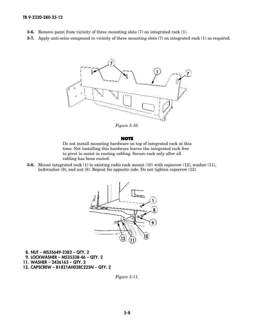
5-8
3-6. Remove paint from vicinity of three mounting slots (7) on integrated rack (1).3-7. Apply anti-seize compound to vicinity of three mounting slots (7) on integrated rack (1) as required.
Figure 5-10.
1 7
7
NNOOTTEEDo not install mounting hardware on top of integrated rack at thistime. Not installing this hardware leaves the integrated rack freeto pivot to assist in routing cabling. Secure rack only after allcabling has been routed.
3-8. Mount integrated rack (1) to existing radio rack mount (10) with capscrew (12), washer (11),lockwasher (9), and nut (8). Repeat for opposite side. Do not tighten capscrew (12).
Figure 5-11.
8
9
1012 11
8. NUT – MS35649-2382 – QTY. 29. LOCKWASHER – MS35338-46 – QTY. 2
11. WASHER – 2436163 – QTY. 212. CAPSCREW – B1821AH038C225N – QTY. 2
~1
TB 9-2320-280-35-12
5-9
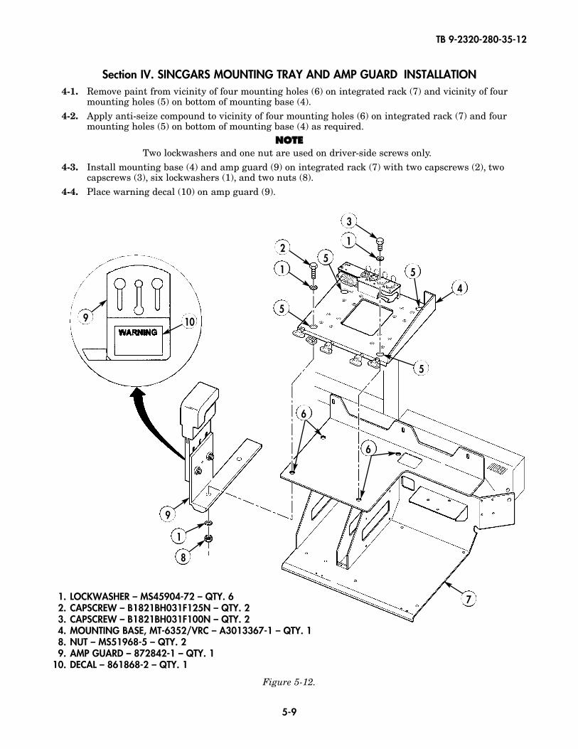
Section IV. SINCGARS MOUNTING TRAY AND AMP GUARD INSTALLATION4-1. Remove paint from vicinity of four mounting holes (6) on integrated rack (7) and vicinity of four
mounting holes (5) on bottom of mounting base (4).4-2. Apply anti-seize compound to vicinity of four mounting holes (6) on integrated rack (7) and four
mounting holes (5) on bottom of mounting base (4) as required.NNOOTTEE
Two lockwashers and one nut are used on driver-side screws only.4-3. Install mounting base (4) and amp guard (9) on integrated rack (7) with two capscrews (2), two
capscrews (3), six lockwashers (1), and two nuts (8).4-4. Place warning decal (10) on amp guard (9).
Figure 5-12.
1. LOCKWASHER – MS45904-72 – QTY. 62. CAPSCREW – B1821BH031F125N – QTY. 23. CAPSCREW – B1821BH031F100N – QTY. 24. MOUNTING BASE, MT-6352/VRC – A3013367-1 – QTY. 18. NUT – MS51968-5 – QTY. 29. AMP GUARD – 872842-1 – QTY. 1
10. DECAL – 861868-2 – QTY. 1
6
5
1
9 10
21
3
4
7
1
8
9
55
5
6
TB 9-2320-280-35-12
5-10
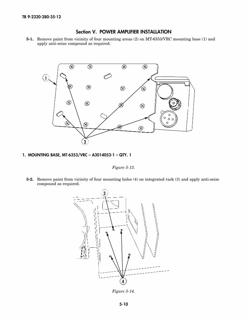
1. MOUNTING BASE, MT-6353/VRC – A3014053-1 – QTY. 1
Section V. POWER AMPLIFIER INSTALLATION5-1. Remove paint from vicinity of four mounting areas (2) on MT-6353/VRC mounting base (1) and
apply anti-seize compound as required.
5-2. Remove paint from vicinity of four mounting holes (4) on integrated rack (3) and apply anti-seizecompound as required.
Figure 5-13.
2
1
Figure 5-14.
4
~
3

TB 9-2320-280-35-12
5-11
5-3. Attach control cable (5) to MT-6353/VRC mounting base (1).5-4. Attach power cable (6) to MT-6353/VRC mounting base (1).
NNOOTTEEEnsure control cable and power cable are routed through hole inback of integrated rack before installing MT-6353/VRC mountingbase. Refer to chapter 5, section XXXI.
5-5. Attach MT-6353/VRC mounting base (1) to integrated rack (3) with two capscrews (9) and (10), fourlockwashers (8), and nut strip (7).
Figure 5-15.
Figure 5-16.
3
7
1
10
8 89
7. NUT STRIP – A3014064-1 – QTY. 18. LOCKWASHER – MS45904-72 – QTY. 49. CAPSCREW – B1821BH031F125N – QTY. 2
10. CAPSCREW – B1821BH031F075N – QTY. 2
51
6
5. CONTROL CABLE – A3014037-4 – QTY. 16. POWER CABLE – A3014040-9 – QTY. 1
TB 9-2320-280-35-12
5-12
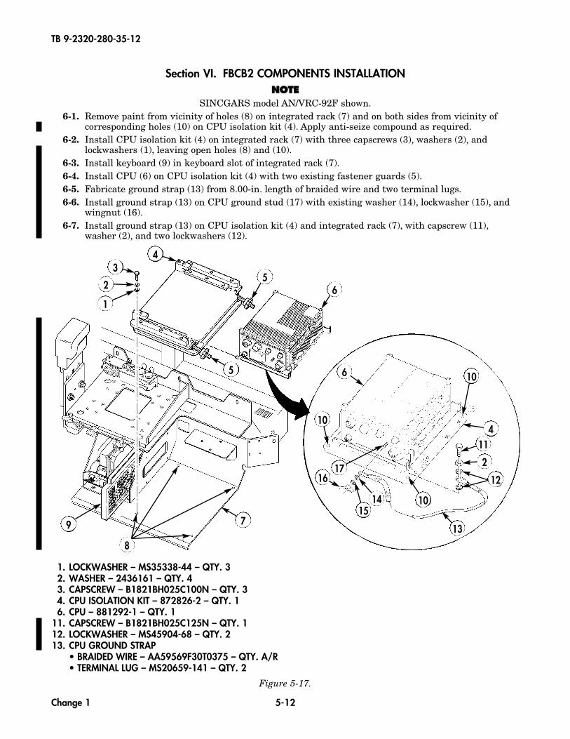
1. LOCKWASHER – MS35338-44 – QTY. 32. WASHER – 2436161 – QTY. 43. CAPSCREW – B1821BH025C100N – QTY. 34. CPU ISOLATION KIT – 872826-2 – QTY. 16. CPU – 881292-1 – QTY. 1
11. CAPSCREW – B1821BH025C125N – QTY. 112. LOCKWASHER – MS45904-68 – QTY. 213. CPU GROUND STRAP
• BRAIDED WIRE – AA59569F30T0375 – QTY. A/R• TERMINAL LUG – MS20659-141 – QTY. 2
Section VI. FBCB2 COMPONENTS INSTALLATIONNNOOTTEE
SINCGARS model AN/VRC-92F shown.6-1. Remove paint from vicinity of holes (8) on integrated rack (7) and on both sides from vicinity of
corresponding holes (10) on CPU isolation kit (4). Apply anti-seize compound as required.6-2. Install CPU isolation kit (4) on integrated rack (7) with three capscrews (3), washers (2), and
lockwashers (1), leaving open holes (8) and (10).6-3. Install keyboard (9) in keyboard slot of integrated rack (7).6-4. Install CPU (6) on CPU isolation kit (4) with two existing fastener guards (5).6-5. Fabricate ground strap (13) from 8.00-in. length of braided wire and two terminal lugs.6-6. Install ground strap (13) on CPU ground stud (17) with existing washer (14), lockwasher (15), and
wingnut (16).6-7. Install ground strap (13) on CPU isolation kit (4) and integrated rack (7), with capscrew (11),
washer (2), and two lockwashers (12).
1
2
34
5
5
6
6
4
10
10
11
2
13
101415
1617
7
12
Figure 5-17.
8
9
Change 1
TB 9-2320-280-35-12
5-12.1
19
20
18 21
22
23
28
27
24
25
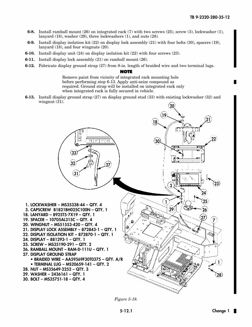
261. LOCKWASHER – MS35338-44 – QTY. 43. CAPSCREW B1821BH025C100N – QTY. 1
18. LANYARD – 8925T5-7X19 – QTY. 119. SPACER – 10705AL315C – QTY. 420. WINGNUT – MS51553-420 – QTY. 421. DISPLAY LOCK ASSEMBLY – 872843-1 – QTY. 122. DISPLAY ISOLATION KIT – 872870-1 – QTY. 124. DISPLAY – 881293-1 – QTY. 125. SCREW – MS35190-291 – QTY. 226. RAMBALL MOUNT – RAM-D-111U – QTY. 127. DISPLAY GROUND STRAP
• BRAIDED WIRE – AA59569F30T0375 – QTY. A/R• TERMINAL LUG – MS20659-141 – QTY. 2
28. NUT – MS35649-2252 – QTY. 329. WASHER – 2436161 – QTY. 130. BOLT – MS35751-18 – QTY. 4
6-8. Install ramball mount (26) on integrated rack (7) with two screws (25), screw (3), lockwasher (1),lanyard (18), washer (29), three lockwashers (1), and nuts (28).
6-9. Install display isolation kit (22) on display lock assembly (21) with four bolts (30), spacers (19),lanyard (18), and four wingnuts (20).
6-10. Install display unit (24) on display isolation kit (22) with four screws (23).6-11. Install display lock assembly (21) on ramball mount (26).6-12. Fabricate display ground strap (27) from 8-in. length of braided wire and two terminal lugs.
NNOOTTEERemove paint from vicinity of integrated rack mounting holebefore performing step 6-13. Apply anti-seize compound asrequired. Ground strap will be installed on integrated rack onlywhen integrated rack is fully secured in vehicle.
6-13. Install display ground strap (27) on display ground stud (33) with existing lockwasher (32) andwingnut (31).
Figure 5-18.
29
3
1
30
33
32
31
27
1
Change 1
7
TB 9-2320-280-35-12
5-12.2
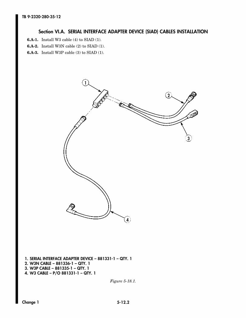
Section VI.A. SERIAL INTERFACE ADAPTER DEVICE (SIAD) CABLES INSTALLATION
6.A-1. Install W3 cable (4) to SIAD (1).
6.A-2. Install W3N cable (2) to SIAD (1).
6.A-3. Install W3P cable (3) to SIAD (1).
Figure 5-18.1.
1
2
1. SERIAL INTERFACE ADAPTER DEVICE – 881331-1 – QTY. 12. W3N CABLE – 881336-1 – QTY. 13. W3P CABLE – 881335-1 – QTY. 14. W3 CABLE – P/O 881331-1 – QTY. 1
3
4
Change 1

TB 9-2320-280-35-12
5-12.3
Section VI.B. SERIAL INTERFACE ADAPTER DEVICE (SIAD) INSTALLATION
Position SIAD (1) securely between FBCB2 (2) and keyboard tray (3) on integrated rack (4).
Figure 5-18.2.
1
2
3
~
4
Change 1

TB 9-2320-280-35-12
5-12.4
Section VI.C. FBCB2 CABLES INSTALLATION
6.C-1. Connect W3 cable (11) from SIAD (13) to J3 connector (9) on FBCB2 processor (7).
6.C-2. Route W3P cable (5) from SIAD (13) to DAGR mount (6).
6.C-3. Connect W2 cable (12) to J4 connector (8) on FBCB2 processor (7) and J1 connector (15) onFBCB2 display unit (4).
6.C-4. Connect W1 cable (2) to J1 connector (10) on FBCB2 processor (7). Route W1 cable (2) to A4J2 connector (17).
6.C-5. Connect keyboard cable (14) to J2 connector (16) on FBCB2 display unit (4).
6.C-6. Route W1J1 cable (3) to SINCGARS mount (1).
Figure 5-18.3.
1 2
3
4
7
8
10
2
11
12
13
~
~
2. W1 CABLE – 866003-3 – QTY. 112. W2 CABLE – 881327-1 – QTY. 1
5
6
914
15
16
17
Change 1
TB 9-2320-280-35-12
5-13
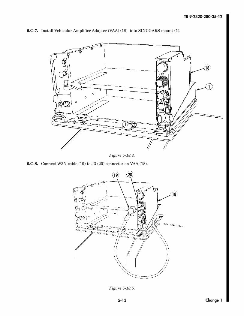
6.C-7. Install Vehicular Amplifier Adapter (VAA) (18) into SINCGARS mount (1).
Figure 5-18.4.
6.C-8. Connect W3N cable (19) to J3 (20) connector on VAA (18).
Figure 5-18.5.
18
1
19 20
18
Change 1
TB 9-2320-280-35-12
5-14
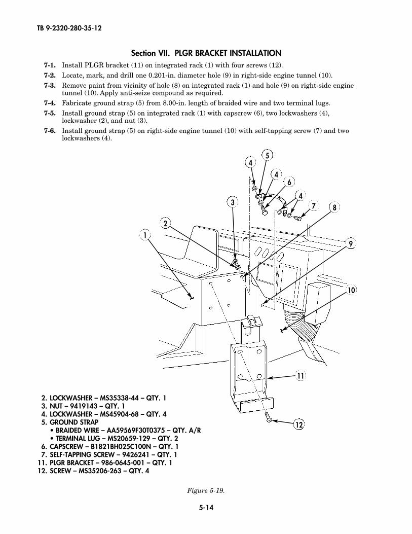
Section VII. PLGR BRACKET INSTALLATION7-1. Install PLGR bracket (11) on integrated rack (1) with four screws (12).7-2. Locate, mark, and drill one 0.201-in. diameter hole (9) in right-side engine tunnel (10).7-3. Remove paint from vicinity of hole (8) on integrated rack (1) and hole (9) on right-side engine
tunnel (10). Apply anti-seize compound as required.7-4. Fabricate ground strap (5) from 8.00-in. length of braided wire and two terminal lugs.7-5. Install ground strap (5) on integrated rack (1) with capscrew (6), two lockwashers (4),
lockwasher (2), and nut (3).7-6. Install ground strap (5) on right-side engine tunnel (10) with self-tapping screw (7) and two
lockwashers (4).
Figure 5-19.
~
~
1
2
3
5
6
47 8
9
10
11
12
4
4
2. LOCKWASHER – MS35338-44 – QTY. 13. NUT – 9419143 – QTY. 14. LOCKWASHER – MS45904-68 – QTY. 45. GROUND STRAP
• BRAIDED WIRE – AA59569F30T0375 – QTY. A/R• TERMINAL LUG – MS20659-129 – QTY. 2
6. CAPSCREW – B1821BH025C100N – QTY. 17. SELF-TAPPING SCREW – 9426241 – QTY. 1
11. PLGR BRACKET – 986-0645-001 – QTY. 112. SCREW – MS35206-263 – QTY. 4
TB 9-2320-280-35-12
5-15
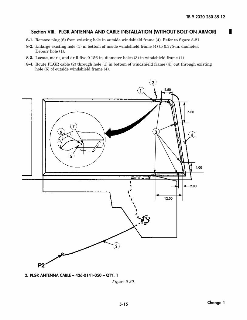
Section VIII. PLGR ANTENNA AND CABLE INSTALLATION (WITHOUT BOLT-ON ARMOR)
8-1. Remove plug (6) from existing hole in outside windshield frame (4). Refer to figure 5-21.
8-2. Enlarge existing hole (1) in bottom of inside windshield frame (4) to 0.375-in. diameter.Deburr hole (1).
8-3. Locate, mark, and drill five 0.156-in. diameter holes (3) in windshield frame (4)
8-4. Route PLGR cable (2) through hole (1) in bottom of windshield frame (4), out through existing hole (6) of outside windshield frame (4).
Figure 5-20.
2
2
4
1
~
2.50
6.00
4.00
2.00
12.00
2. PLGR ANTENNA CABLE – 426-0141-050 – QTY. 1
3
Change 1
5
67
TB 9-2320-280-35-12
5-16
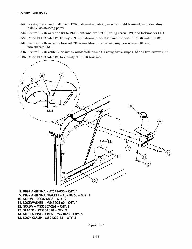
8. PLGR ANTENNA – AT575-030 – QTY. 19. PLGR ANTENNA BRACKET – A3210768 – QTY. 1
10. SCREW – 90087A836 – QTY. 211. LOCKWASHER – MS45904-60 – QTY. 112. SCREW – MS35207-261 – QTY. 113. SPACER – 92510A318 – QTY. 214. SELF-TAPPING SCREW – 9421073 – QTY. 515. LOOP CLAMP – MS21333-65 – QTY. 5
8-5. Locate, mark, and drill one 0.173-in. diameter hole (5) in windshield frame (4) using existing hole (7) as starting point.
8-6. Secure PLGR antenna (8) to PLGR antenna bracket (9) using screw (12), and lockwasher (11).
8-7. Route PLGR cable (2) through PLGR antenna bracket (9) and connect to PLGR antenna (8).
8-8. Secure PLGR antenna bracket (9) to windshield frame (4) using two screws (10) and two spacers (13).
8-9. Secure PLGR cable (2) to inside windshield frame (4) using five clamps (15) and five screws (14).
8-10. Route PLGR cable (2) to vicinity of PLGR bracket.
Figure 5-21.
8
9
1011
12
13
14
15
2
45
6 7
~
2.125
TB 9-2320-280-35-12
5-17
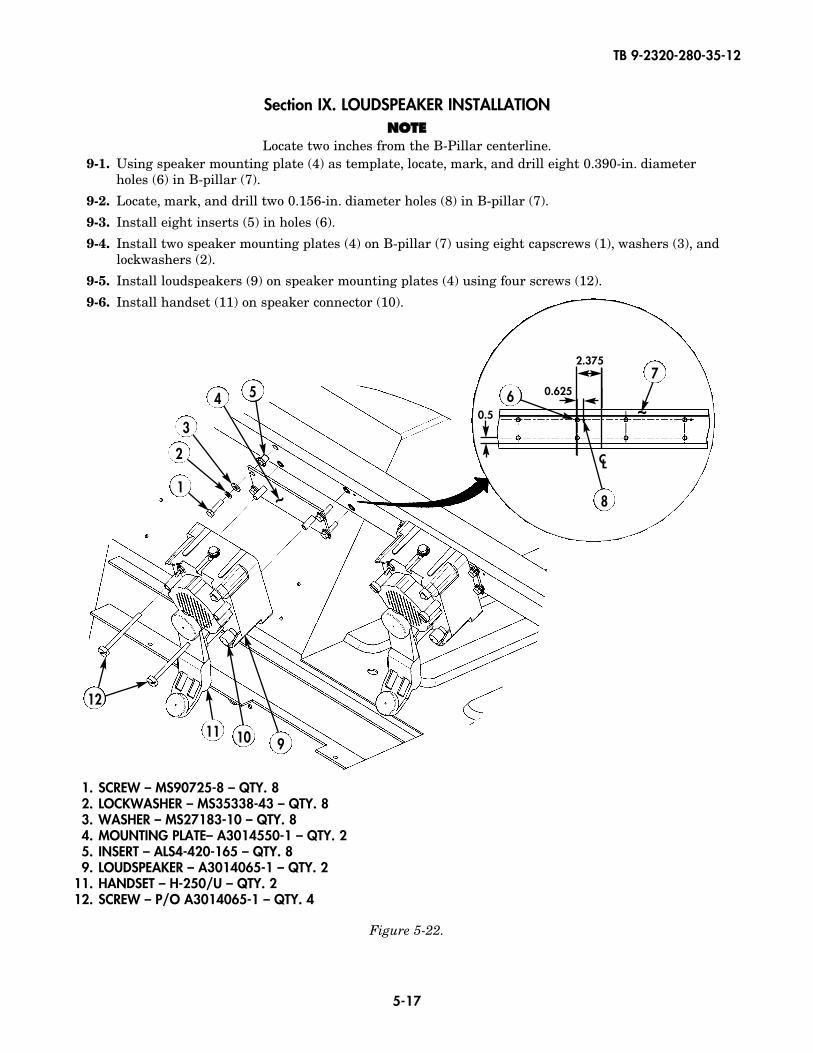
1. SCREW – MS90725-8 – QTY. 82. LOCKWASHER – MS35338-43 – QTY. 83. WASHER – MS27183-10 – QTY. 84. MOUNTING PLATE– A3014550-1 – QTY. 25. INSERT – ALS4-420-165 – QTY. 89. LOUDSPEAKER – A3014065-1 – QTY. 2
11. HANDSET – H-250/U – QTY. 212. SCREW – P/O A3014065-1 – QTY. 4
2
1
3
4 5
Figure 5-22.
Section IX. LOUDSPEAKER INSTALLATIONNNOOTTEE
Locate two inches from the B-Pillar centerline.9-1. Using speaker mounting plate (4) as template, locate, mark, and drill eight 0.390-in. diameter
holes (6) in B-pillar (7).
9-2. Locate, mark, and drill two 0.156-in. diameter holes (8) in B-pillar (7).
9-3. Install eight inserts (5) in holes (6).
9-4. Install two speaker mounting plates (4) on B-pillar (7) using eight capscrews (1), washers (3), andlockwashers (2).
9-5. Install loudspeakers (9) on speaker mounting plates (4) using four screws (12).
9-6. Install handset (11) on speaker connector (10).
12
11 10 9
CL
7
6
8
0.5
2.375
0.625
~
~
TB 9-2320-280-35-12
5-18
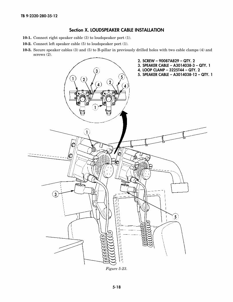
Section X. LOUDSPEAKER CABLE INSTALLATION
10-1. Connect right speaker cable (3) to loudspeaker port (1).
10-2. Connect left speaker cable (5) to loudspeaker port (1).
10-3. Secure speaker cables (3) and (5) to B-pillar in previously drilled holes with two cable clamps (4) andscrews (2).
1
3
5
1
1
22
35
4 4
Figure 5-23.
2. SCREW – 90087A829 – QTY. 23. SPEAKER CABLE – A3014038-3 – QTY. 14. LOOP CLAMP – 3225T44 – QTY. 25. SPEAKER CABLE – A3014038-12 – QTY. 1
TB 9-2320-280-35-12
5-19
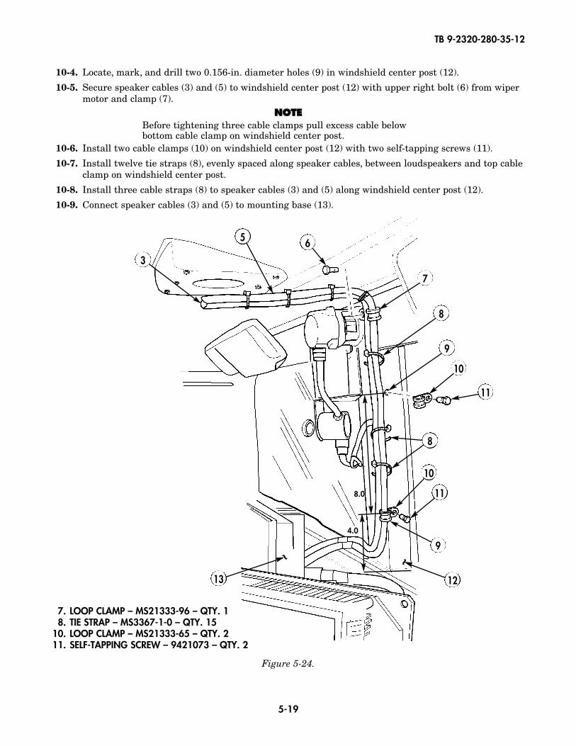
10-4. Locate, mark, and drill two 0.156-in. diameter holes (9) in windshield center post (12).
10-5. Secure speaker cables (3) and (5) to windshield center post (12) with upper right bolt (6) from wipermotor and clamp (7).
NNOOTTEEBefore tightening three cable clamps pull excess cable belowbottom cable clamp on windshield center post.
10-6. Install two cable clamps (10) on windshield center post (12) with two self-tapping screws (11).
10-7. Install twelve tie straps (8), evenly spaced along speaker cables, between loudspeakers and top cableclamp on windshield center post.
10-8. Install three cable straps (8) to speaker cables (3) and (5) along windshield center post (12).
10-9. Connect speaker cables (3) and (5) to mounting base (13).
Figure 5-24.
5 6
7
10
8
9
10
11
12
9
11
3
8
~
13
~
8.0
4.0
7. LOOP CLAMP – MS21333-96 – QTY. 18. TIE STRAP – MS3367-1-0 – QTY. 15
10. LOOP CLAMP – MS21333-65 – QTY. 211. SELF-TAPPING SCREW – 9421073 – QTY. 2

TB 9-2320-280-35-12
5-20
Figure 5-26.
2. INSERT – ALS4-420-165 – QTY. 63. WASHER – MS27183-10 – QTY. 64. LOCKWASHER – MS35338-44 – QTY. 65. CAPSCREW – MS90725-10 – QTY. 66. COMPUTER STAND ASSEMBLY – A3265632 – QTY. 1
Figure 5-25.
Section XI. COMPUTER STAND ASSEMBLY INSTALLATION
11-1. Locate, mark, and drill six .380-in. diameter holes (1).
11-2. Install inserts (2) in holes (1).
11-3. Position laptop housing assembly (6) over inserts (2) in cargo floor (7).
11-4. Install laptop housing assembly (6) in cargo floor (7) with six screws (5), lockwashers (4), and washers (3).
1
4.5
2.245
2 3 4 56~
7~

TB 9-2320-280-35-12
5-21
Figure 5-27.
Section XII. URO BRACKET INSTALLATION
12-1. Locate predrilled holes (7) in rear wall of computer stand (3).
12-2. Secure URO brackets (2) to computer stand (3) with eight screws (9), sixteen washers (6), eightspacers (8), lockwashers (5), and nuts (4).
12-3. Secure URO cables (10) to URO brackets (2) with eight bolts (1) and nuts (11).
3
1 2
~
45678
69
11
10
1. MACHINE SCREW – MS35206-217 – QTY. 82. URO BRACKET – A3006206-2 – QTY. 24. NUT – MS35650-302 – QTY. 85. LOCKWASHER – MS35338-43 – QTY. 86. WASHER – MS27183-8 – QTY. 168. SPACER – 92510A318 – QTY. 89. SCREW – MS35207-268 – QTY. 8
10. URO CABLE – A3005328 – QTY. 211. NUT – 90675A005 – QTY. 8
TB 9-2320-280-35-12
5-22
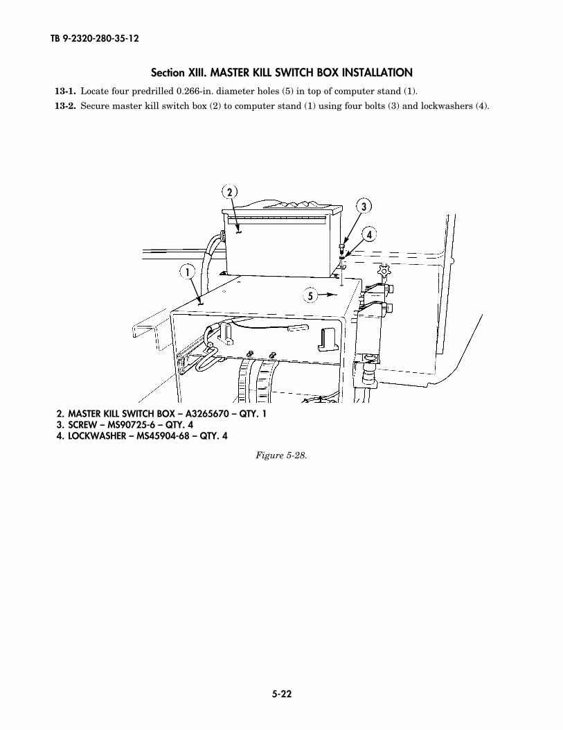
Section XIII. MASTER KILL SWITCH BOX INSTALLATION
13-1. Locate four predrilled 0.266-in. diameter holes (5) in top of computer stand (1).
13-2. Secure master kill switch box (2) to computer stand (1) using four bolts (3) and lockwashers (4).
3
1
2
~
~ 4
5
Figure 5-28.
2. MASTER KILL SWITCH BOX – A3265670 – QTY. 13. SCREW – MS90725-6 – QTY. 44. LOCKWASHER – MS45904-68 – QTY. 4
TB 9-2320-280-35-12
5-23
Figure 5-29.
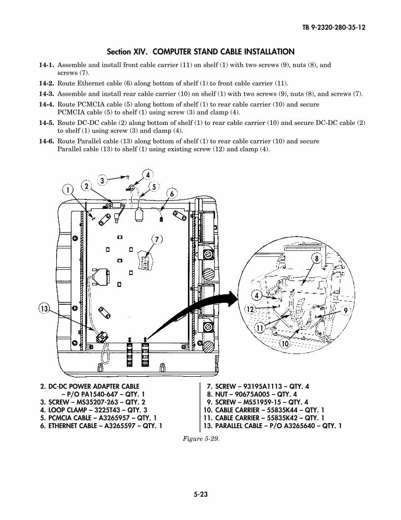
2. DC-DC POWER ADAPTER CABLE– P/O PA1540-647 – QTY. 1
3. SCREW – MS35207-263 – QTY. 24. LOOP CLAMP – 3225T43 – QTY. 35. PCMCIA CABLE – A3265957 – QTY. 16. ETHERNET CABLE – A3265597 – QTY. 1
7. SCREW – 93195A1113 – QTY. 48. NUT – 90675A005 – QTY. 49. SCREW – MS51959-15 – QTY. 4
10. CABLE CARRIER – 55835K44 – QTY. 111. CABLE CARRIER – 55835K42 – QTY. 113. PARALLEL CABLE – P/O A3265640 – QTY. 1
Section XIV. COMPUTER STAND CABLE INSTALLATION
14-1. Assemble and install front cable carrier (11) on shelf (1) with two screws (9), nuts (8), and screws (7).
14-2. Route Ethernet cable (6) along bottom of shelf (1) to front cable carrier (11).
14-3. Assemble and install rear cable carrier (10) on shelf (1) with two screws (9), nuts (8), and screws (7).
14-4. Route PCMCIA cable (5) along bottom of shelf (1) to rear cable carrier (10) and secure PCMCIA cable (5) to shelf (1) using screw (3) and clamp (4).
14-5. Route DC-DC cable (2) along bottom of shelf (1) to rear cable carrier (10) and secure DC-DC cable (2)to shelf (1) using screw (3) and clamp (4).
14-6. Route Parallel cable (13) along bottom of shelf (1) to rear cable carrier (10) and secure Parallel cable (13) to shelf (1) using existing screw (12) and clamp (4).
23
4
56
7
1
~
13
8
9
10
11
12
4
TB 9-2320-280-35-12
5-24
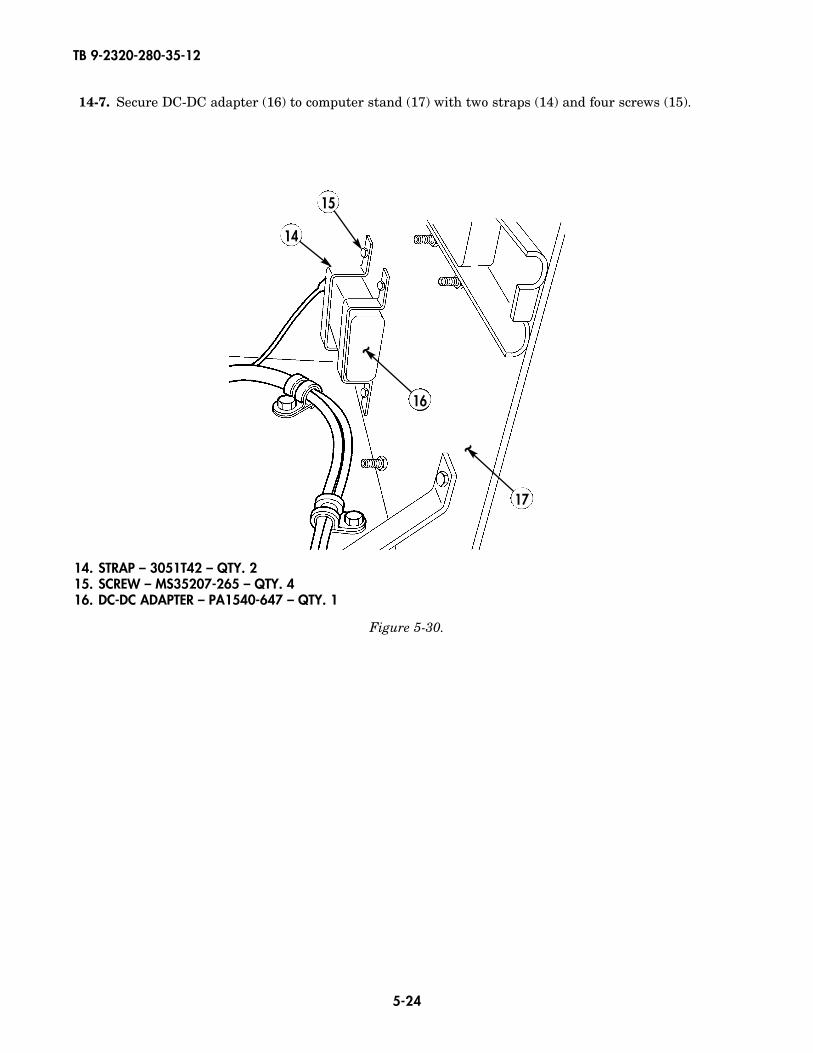
14-7. Secure DC-DC adapter (16) to computer stand (17) with two straps (14) and four screws (15).
14
15
17
~
16
~
Figure 5-30.
14. STRAP – 3051T42 – QTY. 215. SCREW – MS35207-265 – QTY. 416. DC-DC ADAPTER – PA1540-647 – QTY. 1
TB 9-2320-280-35-12
5-25
2
1 1
1
Figure 5-31.
Figure 5-32.
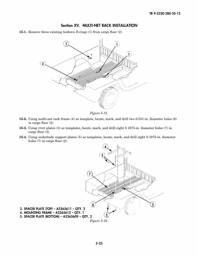
3. SPACER PLATE (TOP) – A3265611 – QTY. 24. MOUNTING FRAME – A3265612 – QTY. 15. SPACER PLATE (BOTTOM) – A3265609 – QTY. 2
~
Section XV. MULTI-NET RACK INSTALLATION
15-1. Remove three existing tiedown D-rings (1) from cargo floor (2).
15-2. Using multi-net rack frame (4) as template, locate, mark, and drill two 0.531-in. diameter holes (6)in cargo floor (2).
15-3. Using rivet plates (3) as templates, locate, mark, and drill eight 0.1875-in. diameter holes (7) incargo floor (2).
15-4. Using underbody support plates (5) as templates, locate, mark, and drill eight 0.1875-in. diameterholes (7) in cargo floor (2).
3
7
6
4
5
5
~
TB 9-2320-280-35-12
5-26
Figure 5-33.
Figure 5-34.
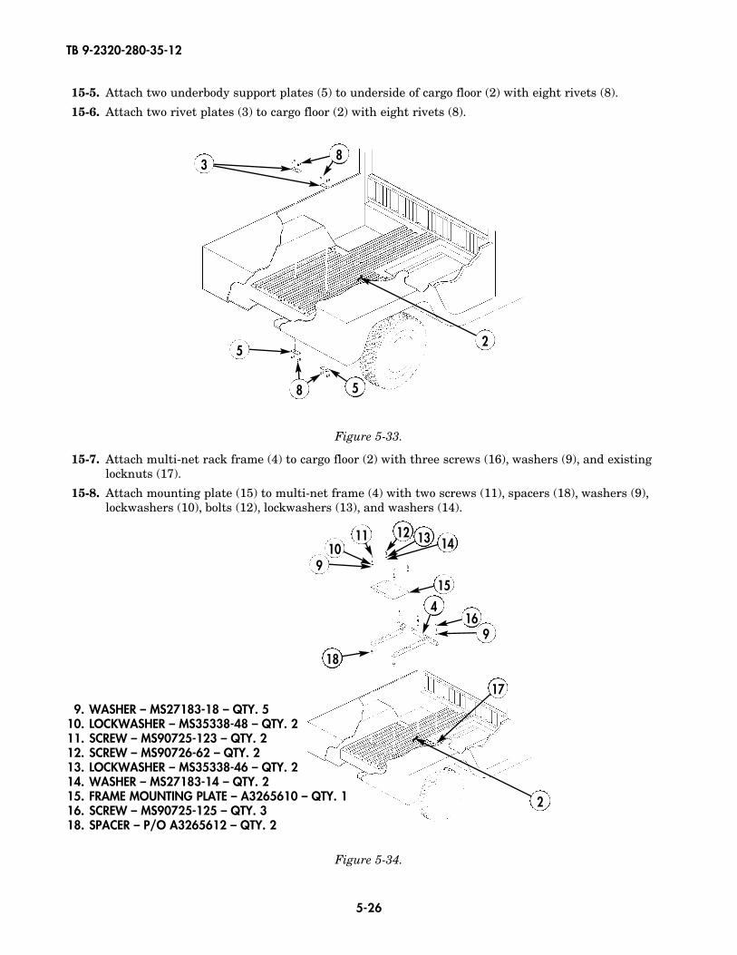
15-7. Attach multi-net rack frame (4) to cargo floor (2) with three screws (16), washers (9), and existinglocknuts (17).
15-8. Attach mounting plate (15) to multi-net frame (4) with two screws (11), spacers (18), washers (9),lockwashers (10), bolts (12), lockwashers (13), and washers (14).
~
3
2
8
5
58
15-5. Attach two underbody support plates (5) to underside of cargo floor (2) with eight rivets (8).
15-6. Attach two rivet plates (3) to cargo floor (2) with eight rivets (8).
9. WASHER – MS27183-18 – QTY. 510. LOCKWASHER – MS35338-48 – QTY. 211. SCREW – MS90725-123 – QTY. 212. SCREW – MS90726-62 – QTY. 213. LOCKWASHER – MS35338-46 – QTY. 214. WASHER – MS27183-14 – QTY. 215. FRAME MOUNTING PLATE – A3265610 – QTY. 116. SCREW – MS90725-125 – QTY. 318. SPACER – P/O A3265612 – QTY. 2
910
11 12 13 14
15
16
17
9
4
18
~
2
TB 9-2320-280-35-12
5-27
Figure 5-35.
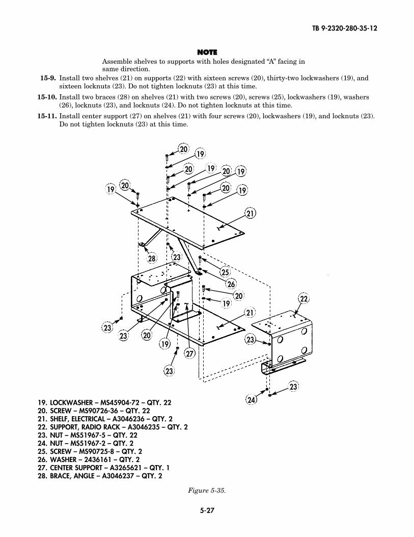
NNOOTTEEAssemble shelves to supports with holes designated “A” facing insame direction.
15-9. Install two shelves (21) on supports (22) with sixteen screws (20), thirty-two lockwashers (19), andsixteen locknuts (23). Do not tighten locknuts (23) at this time.
15-10. Install two braces (28) on shelves (21) with two screws (20), screws (25), lockwashers (19), washers(26), locknuts (23), and locknuts (24). Do not tighten locknuts at this time.
15-11. Install center support (27) on shelves (21) with four screws (20), lockwashers (19), and locknuts (23).Do not tighten locknuts (23) at this time.
19. LOCKWASHER – MS45904-72 – QTY. 2220. SCREW – MS90726-36 – QTY. 2221. SHELF, ELECTRICAL – A3046236 – QTY. 222. SUPPORT, RADIO RACK – A3046235 – QTY. 223. NUT – MS51967-5 – QTY. 2224. NUT – MS51967-2 – QTY. 225. SCREW – MS90725-8 – QTY. 226. WASHER – 2436161 – QTY. 227. CENTER SUPPORT – A3265621 – QTY. 128. BRACE, ANGLE – A3046237 – QTY. 2
~
~
~
2019
2019 20
21
~
21
25
20 22
23
19
26
19
20 19 20 19
23
24
27
23
192023
23
2328
TB 9-2320-280-35-12
5-28
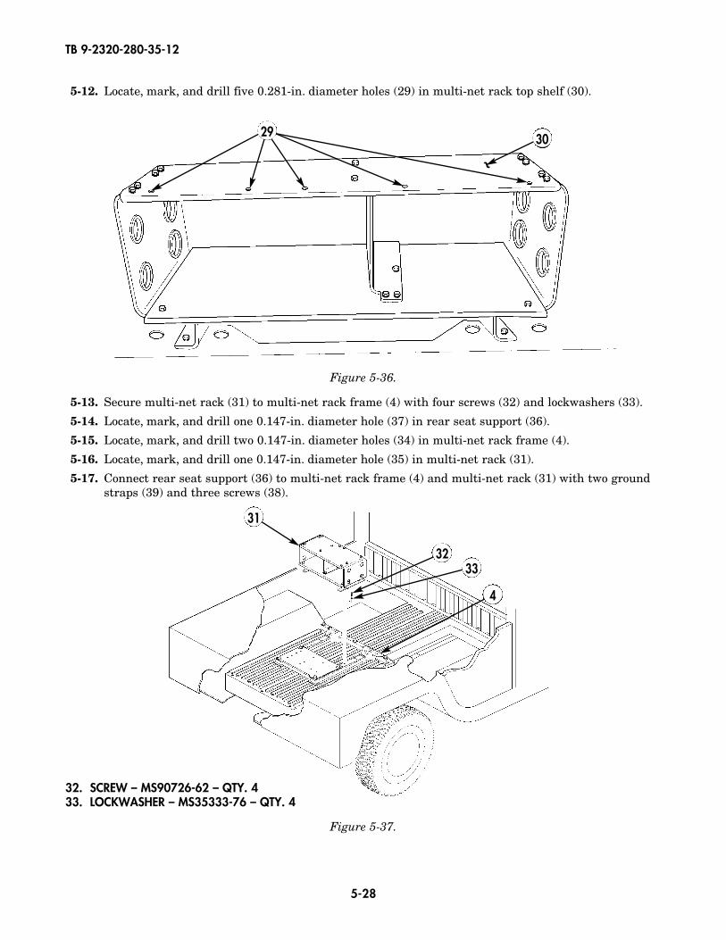
32. SCREW – MS90726-62 – QTY. 433. LOCKWASHER – MS35333-76 – QTY. 4
Figure 5-37.
3233
4
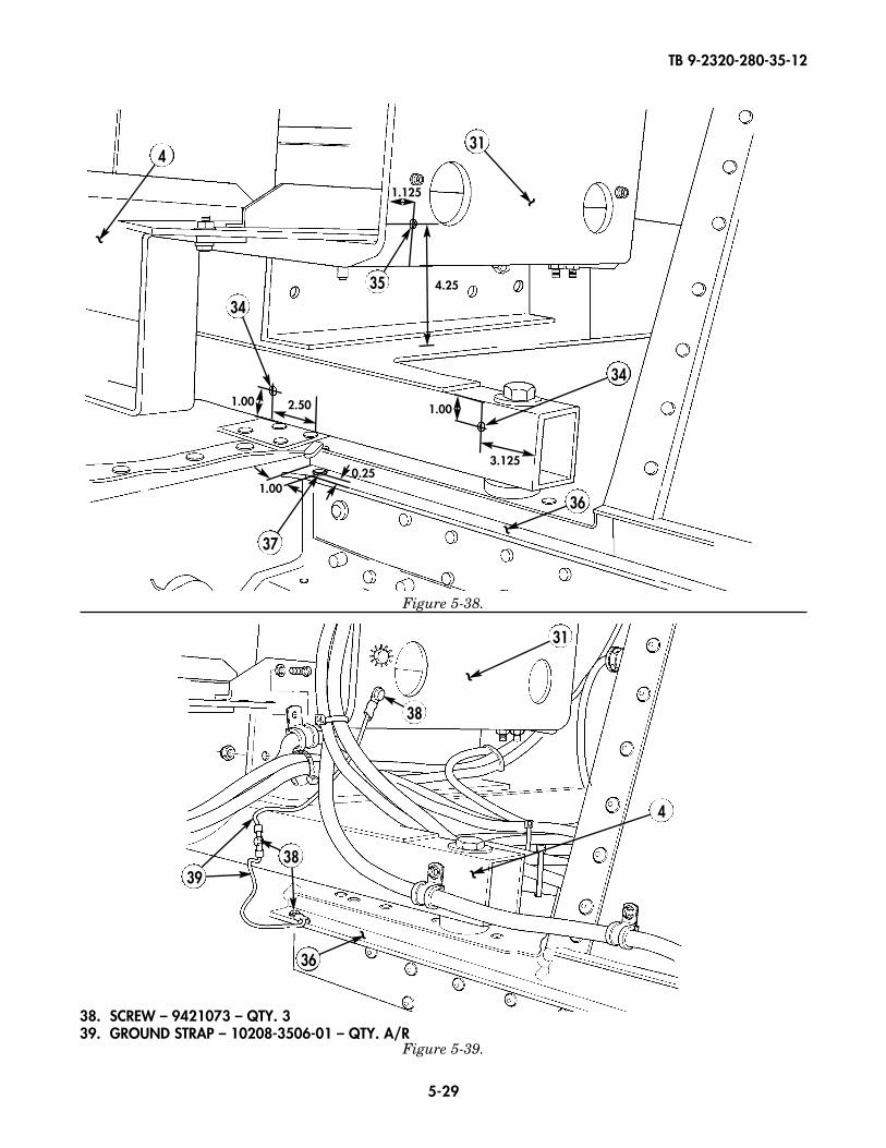
5-13. Secure multi-net rack (31) to multi-net rack frame (4) with four screws (32) and lockwashers (33).
5-14. Locate, mark, and drill one 0.147-in. diameter hole (37) in rear seat support (36).
5-15. Locate, mark, and drill two 0.147-in. diameter holes (34) in multi-net rack frame (4).
5-16. Locate, mark, and drill one 0.147-in. diameter hole (35) in multi-net rack (31).
5-17. Connect rear seat support (36) to multi-net rack frame (4) and multi-net rack (31) with two groundstraps (39) and three screws (38).
Figure 5-36.
5-12. Locate, mark, and drill five 0.281-in. diameter holes (29) in multi-net rack top shelf (30).
~
31
3029
TB 9-2320-280-35-12
5-29
38. SCREW – 9421073 – QTY. 339. GROUND STRAP – 10208-3506-01 – QTY. A/R
Figure 5-38.
Figure 5-39.
35
31
34
34
37
36~
~1.00
1.000.25
2.50
1.125
4.25
1.00
3.125
4
~4
31
38
~
~
~
3938
36
TB 9-2320-280-35-12
5-30
Figure 5-40.
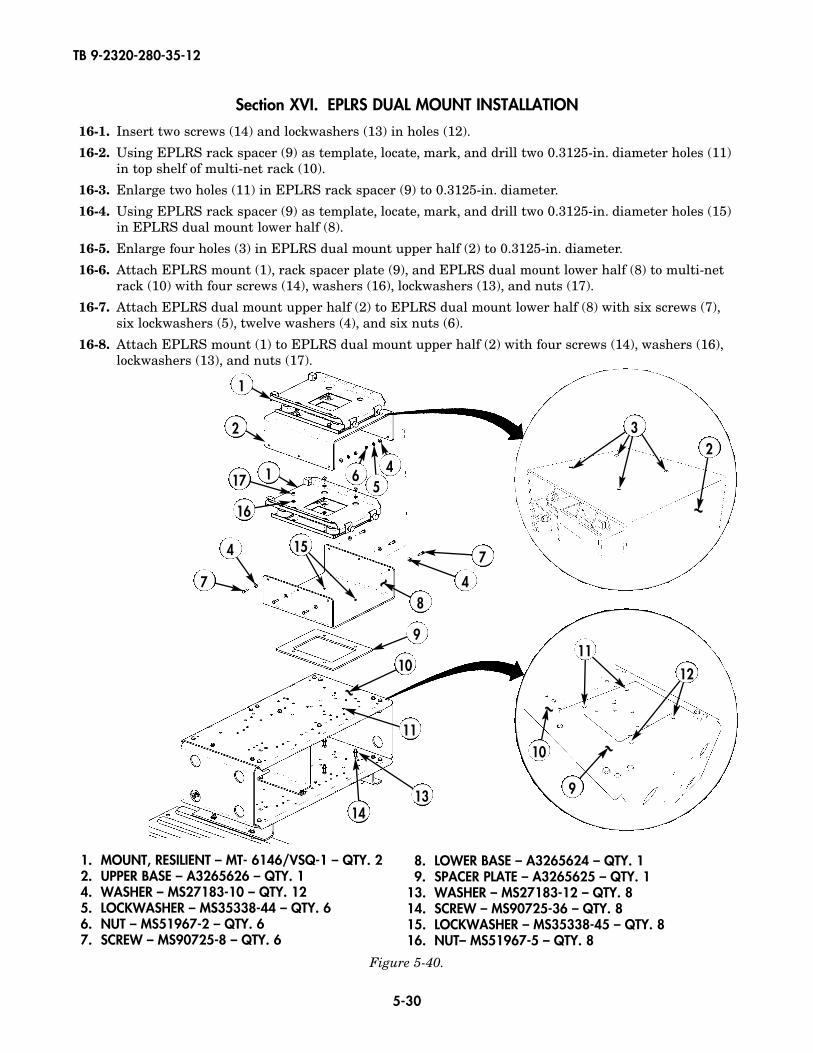
Section XVI. EPLRS DUAL MOUNT INSTALLATION
16-1. Insert two screws (14) and lockwashers (13) in holes (12).
16-2. Using EPLRS rack spacer (9) as template, locate, mark, and drill two 0.3125-in. diameter holes (11)in top shelf of multi-net rack (10).
16-3. Enlarge two holes (11) in EPLRS rack spacer (9) to 0.3125-in. diameter.
16-4. Using EPLRS rack spacer (9) as template, locate, mark, and drill two 0.3125-in. diameter holes (15)in EPLRS dual mount lower half (8).
16-5. Enlarge four holes (3) in EPLRS dual mount upper half (2) to 0.3125-in. diameter.
16-6. Attach EPLRS mount (1), rack spacer plate (9), and EPLRS dual mount lower half (8) to multi-netrack (10) with four screws (14), washers (16), lockwashers (13), and nuts (17).
16-7. Attach EPLRS dual mount upper half (2) to EPLRS dual mount lower half (8) with six screws (7),six lockwashers (5), twelve washers (4), and six nuts (6).
16-8. Attach EPLRS mount (1) to EPLRS dual mount upper half (2) with four screws (14), washers (16),lockwashers (13), and nuts (17).
8
9
11
10
1413
~
~
1
1 65
417
16
7
4
4
7
2 32
~
11
12
9
10 ~
~
1. MOUNT, RESILIENT – MT- 6146/VSQ-1 – QTY. 22. UPPER BASE – A3265626 – QTY. 14. WASHER – MS27183-10 – QTY. 125. LOCKWASHER – MS35338-44 – QTY. 66. NUT – MS51967-2 – QTY. 67. SCREW – MS90725-8 – QTY. 6
8. LOWER BASE – A3265624 – QTY. 19. SPACER PLATE – A3265625 – QTY. 1
13. WASHER – MS27183-12 – QTY. 814. SCREW – MS90725-36 – QTY. 815. LOCKWASHER – MS35338-45 – QTY. 816. NUT– MS51967-5 – QTY. 8
15
TB 9-2320-280-35-12
5-31
Figure 5-41. Figure 5-42.
Figure 5-43. Figure 5-44.
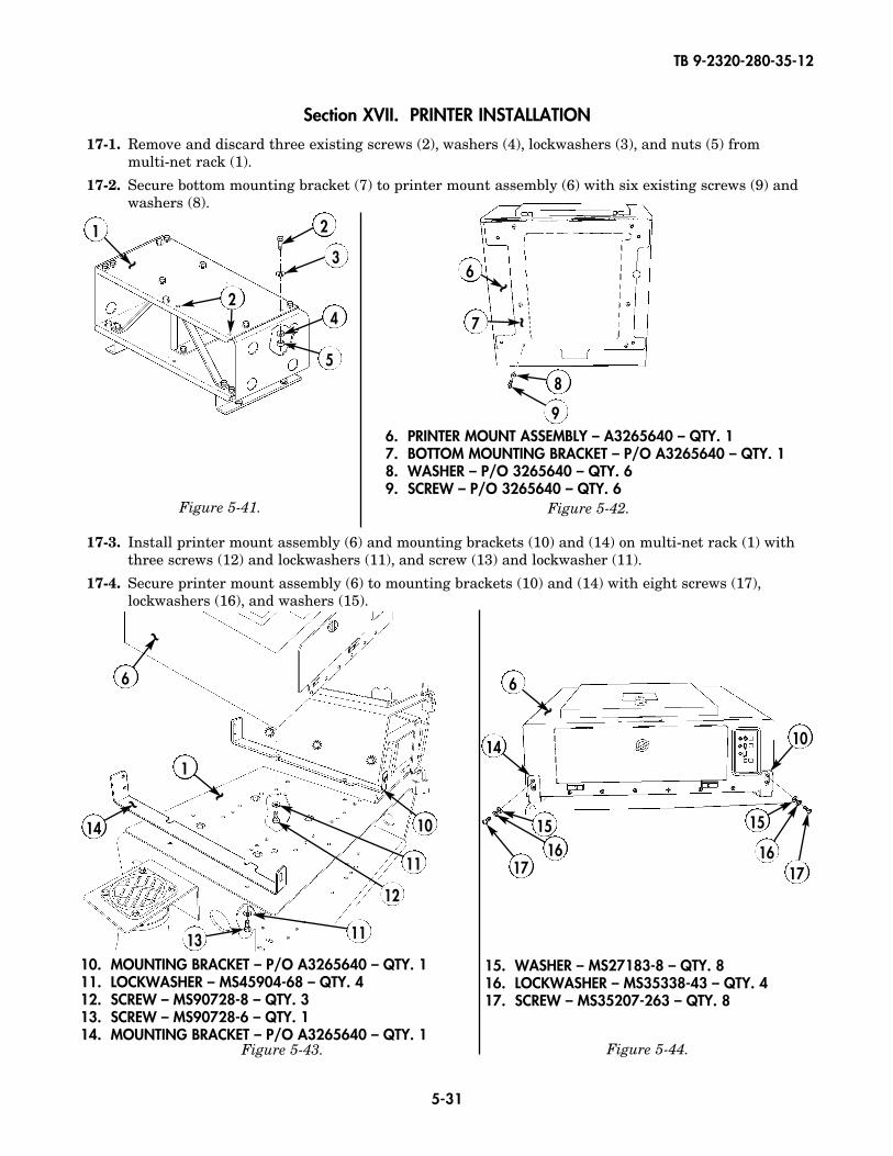
Section XVII. PRINTER INSTALLATION
17-1. Remove and discard three existing screws (2), washers (4), lockwashers (3), and nuts (5) from multi-net rack (1).
17-2. Secure bottom mounting bracket (7) to printer mount assembly (6) with six existing screws (9) andwashers (8).
17-3. Install printer mount assembly (6) and mounting brackets (10) and (14) on multi-net rack (1) withthree screws (12) and lockwashers (11), and screw (13) and lockwasher (11).
17-4. Secure printer mount assembly (6) to mounting brackets (10) and (14) with eight screws (17),lockwashers (16), and washers (15).
~~
~
1 2
3
4
5
6
7
8
96. PRINTER MOUNT ASSEMBLY – A3265640 – QTY. 17. BOTTOM MOUNTING BRACKET – P/O A3265640 – QTY. 18. WASHER – P/O 3265640 – QTY. 69. SCREW – P/O 3265640 – QTY. 6
10. MOUNTING BRACKET – P/O A3265640 – QTY. 111. LOCKWASHER – MS45904-68 – QTY. 412. SCREW – MS90728-8 – QTY. 313. SCREW – MS90728-6 – QTY. 114. MOUNTING BRACKET – P/O A3265640 – QTY. 1
15. WASHER – MS27183-8 – QTY. 816. LOCKWASHER – MS35338-43 – QTY. 417. SCREW – MS35207-263 – QTY. 8
6
1
14 10
12
11
1113
~
~ ~
6
14 10
15 15
16 1617 17
~
2
TB 9-2320-280-35-12
5-32
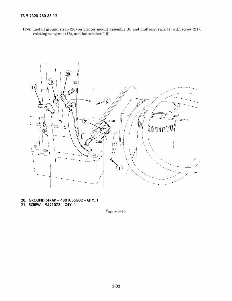
17-5. Install ground strap (20) on printer mount assembly (6) and multi-net rack (1) with screw (21),existing wing nut (18), and lockwasher (19).
~
1
21
~ 6
1819
20
1.50
0.50
Figure 5-45.
20. GROUND STRAP – 4801C3SG02 – QTY. 121. SCREW – 9421073 – QTY. 1
TB 9-2320-280-35-12
5-33
Figure 5-46.
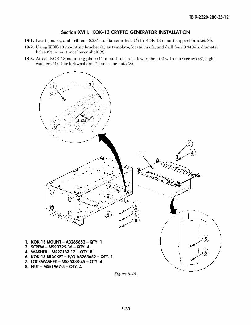
1. KOK-13 MOUNT – A3265652 – QTY. 13. SCREW – MS90725-36 – QTY. 44. WASHER – MS27183-12 – QTY. 86. KOK-13 BRACKET – P/O A3265652 – QTY. 17. LOCKWASHER – MS35338-45 – QTY. 48. NUT – MS51967-5 – QTY. 4
Section XVIII. KOK-13 CRYPTO GENERATOR INSTALLATION
18-1. Locate, mark, and drill one 0.281-in. diameter hole (5) in KOK-13 mount support bracket (6).
18-2. Using KOK-13 mounting bracket (1) as template, locate, mark, and drill four 0.343-in. diameter holes (9) in multi-net lower shelf (2).
18-3. Attach KOK-13 mounting plate (1) to multi-net rack lower shelf (2) with four screws (3), eightwashers (4), four lockwashers (7), and four nuts (8).
~
9
3
4
4
7
8
1
~
2
~
1
~
2
1.875
5
6~

TB 9-2320-280-35-12
5-34
3. BATTERY ALARM BOX – A3265665 – QTY. 14. CAPSCREW – B1821BH025C125N – QTY. 65. WASHER – 2436161 – QTY. 126. LOCKWASHER – MS35338-44 – QTY. 67. NUT – 9419143 – QTY. 6
Figure 5-47.
Figure 5-48.
Section XIX. BATTERY ALARM BOX INSTALLATION19-1. Using battery alarm box as template, locate, mark, and drill four 0.281-in. diameter holes (1) in
multi-net rack (2) lower shelf.
19-2. Install battery alarm box (3) on multi-net rack (2) lower shelf with four screws (4), eight washers (5), four lockwashers (6), and four nuts (7).
1
1
1
1
2
2.125 2.25
~
3
5
2
4
5~
5
6
7
6
5
TB 9-2320-280-35-12
5-35
Figure 5-49.
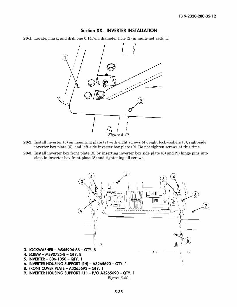
Section XX. INVERTER INSTALLATION
20-1. Locate, mark, and drill one 0.147-in. diameter hole (2) in multi-net rack (1).
20-2. Install inverter (5) on mounting plate (7) with eight screws (4), eight lockwashers (3), right-sideinverter box plate (6), and left-side inverter box plate (9). Do not tighten screws at this time.
20-3. Install inverter box front plate (8) by inserting inverter box side plate (6) and (9) hinge pins intoslots in inverter box front plate (8) and tightening all screws.
1
4 4
9
6
33
2
Figure 5-50.
~
~ ~
7
~
8
~5
~
3. LOCKWASHER – MS45904-68 – QTY. 84. SCREW – MS90725-8 – QTY. 85. INVERTER – 806-1050 – QTY. 16. INVERTER HOUSING SUPPORT (RH) – A3265690 – QTY. 18. FRONT COVER PLATE – A3265693 – QTY. 19. INVERTER HOUSING SUPPORT (LH) – P/O A3265690 – QTY. 1
TB 9-2320-280-35-12
5-36
Figure 5-51.
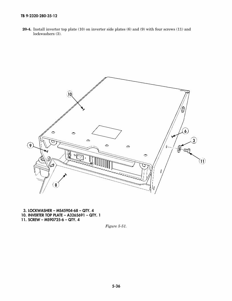
3. LOCKWASHER – MS45904-68 – QTY. 410. INVERTER TOP PLATE – A3265691 – QTY. 111. SCREW – MS90725-6 – QTY. 4
9
8
6
3
11
10
~
~
~
~
20-4. Install inverter top plate (10) on inverter side plates (6) and (9) with four screws (11) andlockwashers (3).

TB 9-2320-280-35-12
5-37
1. SCREW – MS24671-43 – QTY. 42. BOLT CARRIAGE – 93548A652 – QTY. 23. BATTERY – 8A27M – QTY. 14. CHANNEL HOLD DOWN – A3265712 – QTY. 15. WASHER – MS27183-14 – QTY. 26. LOCKWASHER – MS35338-46 – QTY. 27. NUT – MS51967-8 – QTY. 29. BATTERY BOX – A3265709 – QTY. 1
10. BATTERY TRAY – A3265708 – QTY. 1Figure 5-52.
Section XXI. REAR BATTERY BOX INSTALLATION
21-1. Position carriage bolts (2) in rear battery tray (10).
21-2. Install rear battery tray (10) and rear battery box (9) on mounting plate (8) with four screws (1).
21-3. Install rear battery (3) in rear battery tray (10).
21-4. Secure rear battery (3) to rear battery tray (10) with channel hold down (4), two washers (5),lockwashers (6), and nuts (7).
66
55
3
4
77
10
9
8
~
~2
1
1
TB 9-2320-280-35-12
5-38
~1
32 5
6
7
8
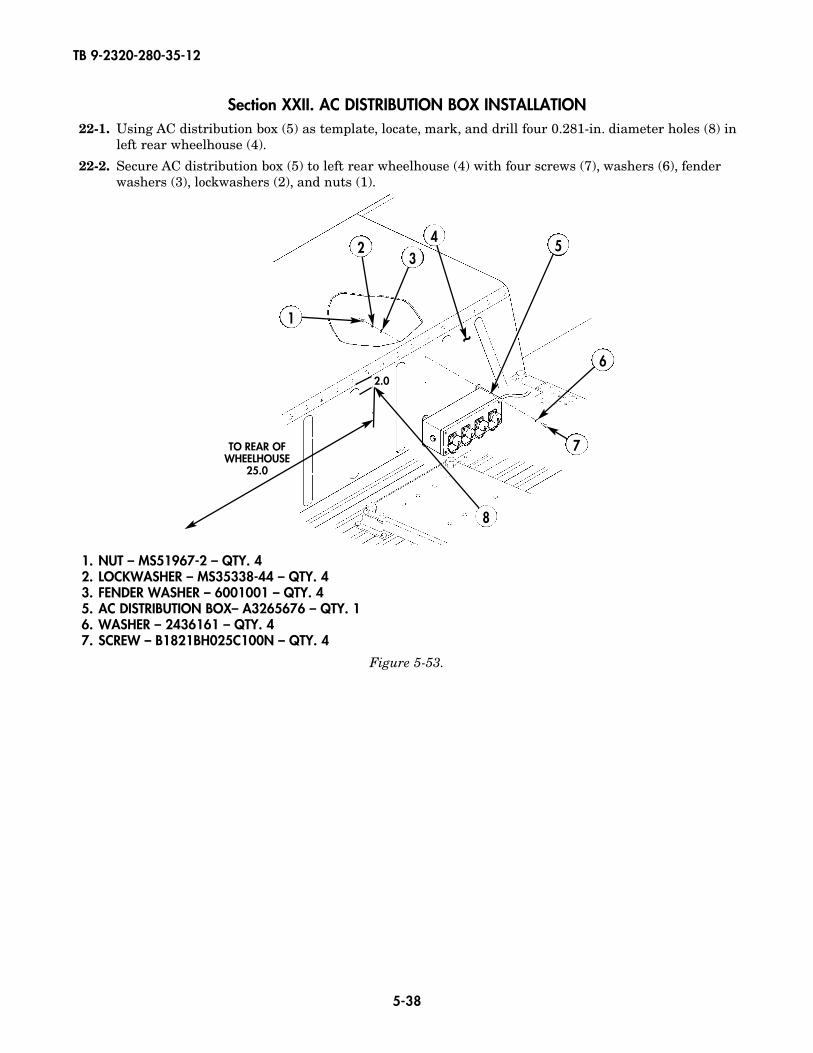
1. NUT – MS51967-2 – QTY. 42. LOCKWASHER – MS35338-44 – QTY. 43. FENDER WASHER – 6001001 – QTY. 45. AC DISTRIBUTION BOX– A3265676 – QTY. 16. WASHER – 2436161 – QTY. 47. SCREW – B1821BH025C100N – QTY. 4
Section XXII. AC DISTRIBUTION BOX INSTALLATION22-1. Using AC distribution box (5) as template, locate, mark, and drill four 0.281-in. diameter holes (8) in
left rear wheelhouse (4).
22-2. Secure AC distribution box (5) to left rear wheelhouse (4) with four screws (7), washers (6), fenderwashers (3), lockwashers (2), and nuts (1).
Figure 5-53.
4
2.0
TO REAR OFWHEELHOUSE
25.0

TB 9-2320-280-35-12
5-39
Section XXIII. AC OUTPUT SELECTION BOX INSTALLATION
23-1. Using AC output selection box (5) as template, locate, mark, and drill four 0.313-in. diameter holes(4) in left rear wheelhouse (8).
23-2. Secure AC output selection box (5) to left rear wheelhouse (8) with four screws (6), washers (7),fender washers (3), lockwashers (2), and nuts (1).
12 3
45
67
8
1. NUT – MS51967-6 – QTY. 42. LOCKWASHER – MS35338-45 – QTY. 43. FENDER WASHER – 90313A112 – QTY. 45. AC OUTPUT SELECTION BOX – A3265686 – QTY. 16. SCREW – B1821BH025C100N – QTY. 47. WASHER – 2436162 – QTY. 4
Figure 5-54.
~ 13.5
TO REAR OF
WHEELHOUSE
2.0
TB 9-2320-280-35-12
5-40
Figure 5-55.
Figure 5-56.
Figure 5-57.
4 5
~~
2
1
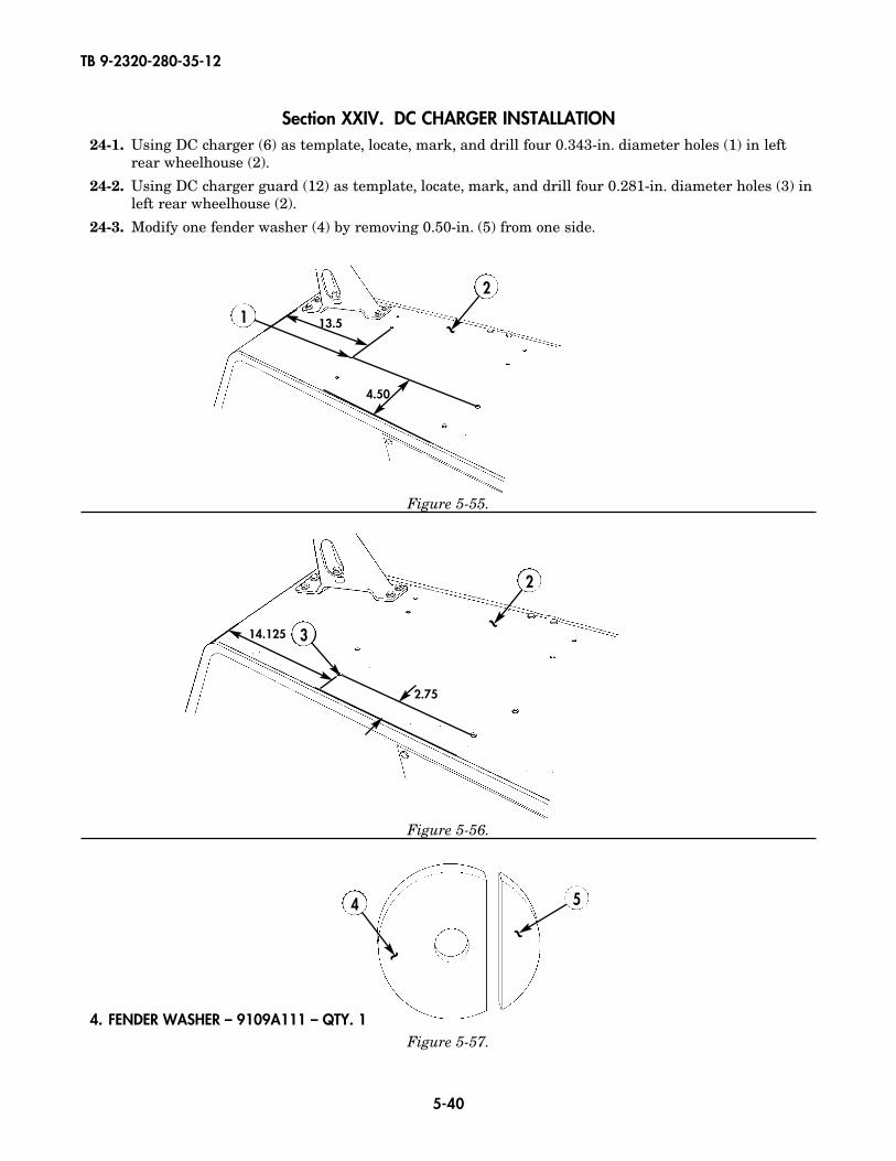
Section XXIV. DC CHARGER INSTALLATION24-1. Using DC charger (6) as template, locate, mark, and drill four 0.343-in. diameter holes (1) in left
rear wheelhouse (2).
24-2. Using DC charger guard (12) as template, locate, mark, and drill four 0.281-in. diameter holes (3) inleft rear wheelhouse (2).
24-3. Modify one fender washer (4) by removing 0.50-in. (5) from one side.
~13.5
4.50
2
3~
14.125
2.75
4. FENDER WASHER – 9109A111 – QTY. 1
TB 9-2320-280-35-12
5-41
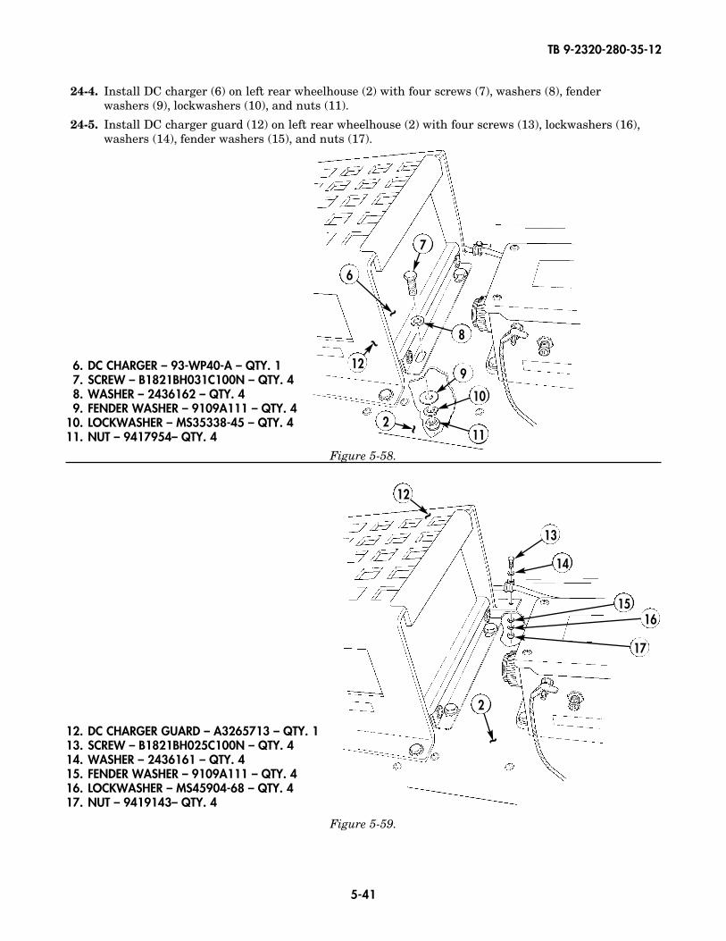
24-4. Install DC charger (6) on left rear wheelhouse (2) with four screws (7), washers (8), fender washers (9), lockwashers (10), and nuts (11).
24-5. Install DC charger guard (12) on left rear wheelhouse (2) with four screws (13), lockwashers (16),washers (14), fender washers (15), and nuts (17).
Figure 5-58.
6. DC CHARGER – 93-WP40-A – QTY. 17. SCREW – B1821BH031C100N – QTY. 48. WASHER – 2436162 – QTY. 49. FENDER WASHER – 9109A111 – QTY. 4
10. LOCKWASHER – MS35338-45 – QTY. 411. NUT – 9417954– QTY. 4
6
7
8
9
10
11
~
12
~
2 ~
12. DC CHARGER GUARD – A3265713 – QTY. 113. SCREW – B1821BH025C100N – QTY. 414. WASHER – 2436161 – QTY. 415. FENDER WASHER – 9109A111 – QTY. 416. LOCKWASHER – MS45904-68 – QTY. 417. NUT – 9419143– QTY. 4
Figure 5-59.
13
14
1516
17
12
~
2
~
TB 9-2320-280-35-12
5-42
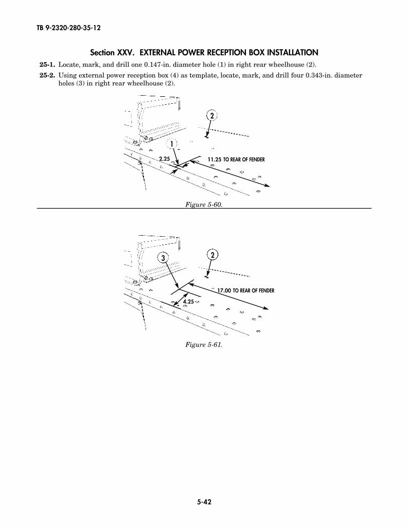
Section XXV. EXTERNAL POWER RECEPTION BOX INSTALLATION25-1. Locate, mark, and drill one 0.147-in. diameter hole (1) in right rear wheelhouse (2).
25-2. Using external power reception box (4) as template, locate, mark, and drill four 0.343-in. diameter holes (3) in right rear wheelhouse (2).
1
2
~
11.25 TO REAR OF FENDER2.25
23
~17.00 TO REAR OF FENDER
4.25
Figure 5-60.
Figure 5-61.
TB 9-2320-280-35-12
5-43
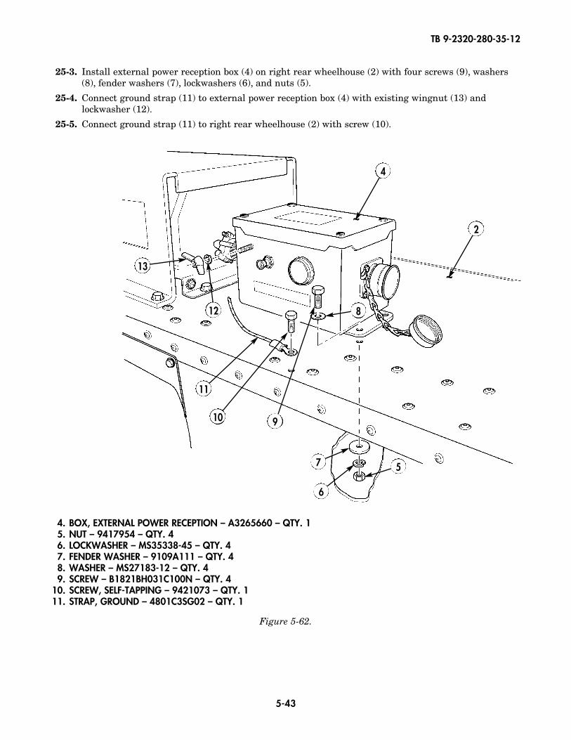
25-3. Install external power reception box (4) on right rear wheelhouse (2) with four screws (9), washers(8), fender washers (7), lockwashers (6), and nuts (5).
25-4. Connect ground strap (11) to external power reception box (4) with existing wingnut (13) andlockwasher (12).
25-5. Connect ground strap (11) to right rear wheelhouse (2) with screw (10).
4. BOX, EXTERNAL POWER RECEPTION – A3265660 – QTY. 15. NUT – 9417954 – QTY. 46. LOCKWASHER – MS35338-45 – QTY. 47. FENDER WASHER – 9109A111 – QTY. 48. WASHER – MS27183-12 – QTY. 49. SCREW – B1821BH031C100N – QTY. 4
10. SCREW, SELF-TAPPING – 9421073 – QTY. 111. STRAP, GROUND – 4801C3SG02 – QTY. 1
2
910
6
7
11
5
812
13
Figure 5-62.
~
4
~
TB 9-2320-280-35-12
5-44
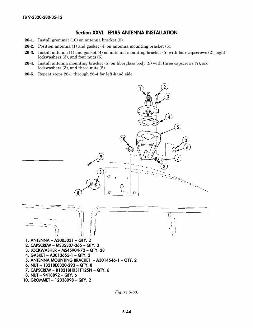
Section XXVI. EPLRS ANTENNA INSTALLATION26-1. Install grommet (10) on antenna bracket (5).26-2. Position antenna (1) and gasket (4) on antenna mounting bracket (5).26-3. Install antenna (1) and gasket (4) on antenna mounting bracket (5) with four capscrews (2), eight
lockwashers (3), and four nuts (6).26-4. Install antenna mounting bracket (5) on fiberglass body (9) with three capscrews (7), six
lockwashers (3), and three nuts (8).26-5. Repeat steps 26-1 through 26-4 for left-hand side.
1. ANTENNA – A3005031 – QTY. 22. CAPSCREW – MS35307-365 – QTY. 33. LOCKWASHER – MS45904-72 – QTY. 284. GASKET – A3013655-1 – QTY. 25. ANTENNA MOUNTING BRACKET – A3014546-1 – QTY. 26. NUT – 13218E0320-293 – QTY. 87. CAPSCREW – B1821BH031F125N – QTY. 68. NUT – 9418892 – QTY. 6
10. GROMMET – 12338098 – QTY. 2
1 2
3
3
3
4
6
9
10
8
7
3
5
Figure 5-63.
~
TB 9-2320-280-35-12
5-45
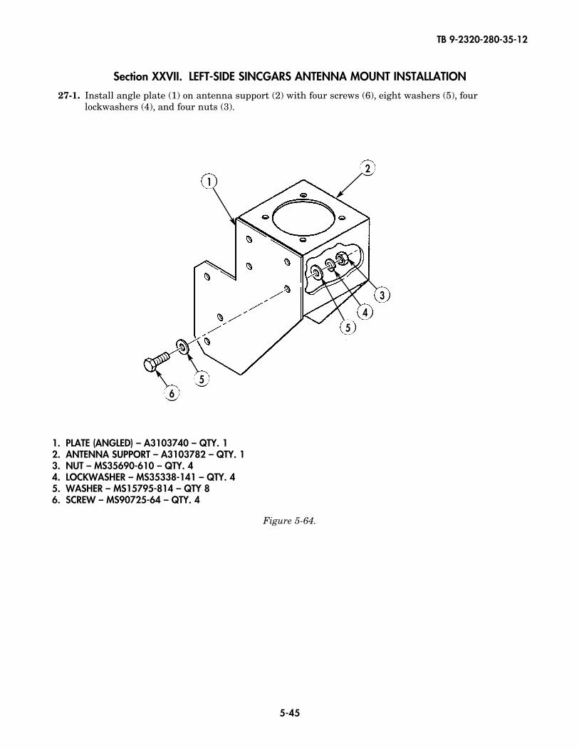
1. PLATE (ANGLED) – A3103740 – QTY. 12. ANTENNA SUPPORT – A3103782 – QTY. 13. NUT – MS35690-610 – QTY. 44. LOCKWASHER – MS35338-141 – QTY. 45. WASHER – MS15795-814 – QTY 86. SCREW – MS90725-64 – QTY. 4
Figure 5-64.
Section XXVII. LEFT-SIDE SINCGARS ANTENNA MOUNT INSTALLATION
27-1. Install angle plate (1) on antenna support (2) with four screws (6), eight washers (5), fourlockwashers (4), and four nuts (3).
2
3
45
56
1
TB 9-2320-280-35-12
5-46
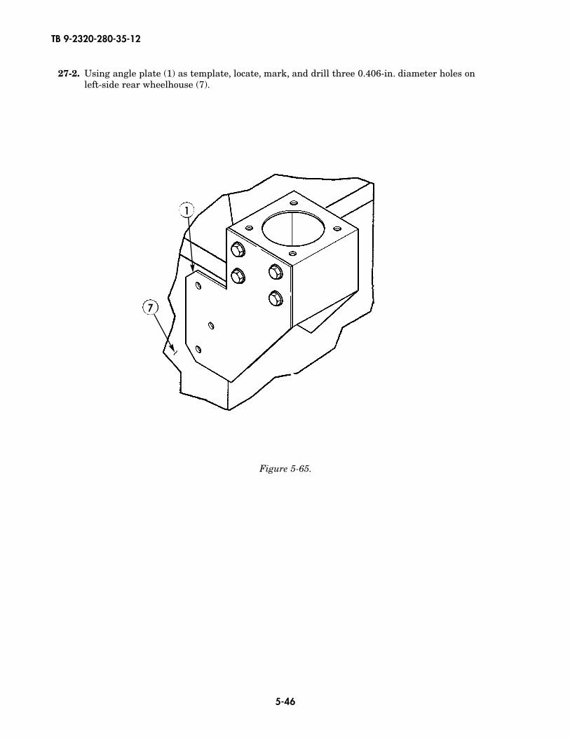
27-2. Using angle plate (1) as template, locate, mark, and drill three 0.406-in. diameter holes on left-side rear wheelhouse (7).
Figure 5-65.
1
7
~
TB 9-2320-280-35-12
5-47
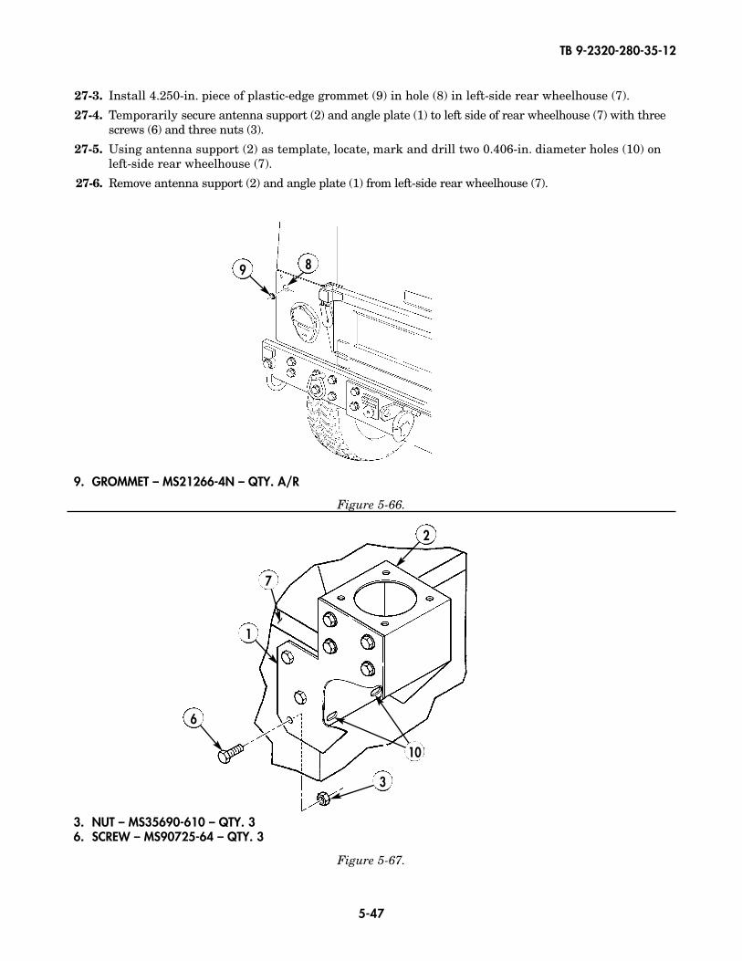
27-3. Install 4.250-in. piece of plastic-edge grommet (9) in hole (8) in left-side rear wheelhouse (7).
27-4. Temporarily secure antenna support (2) and angle plate (1) to left side of rear wheelhouse (7) with threescrews (6) and three nuts (3).
27-5. Using antenna support (2) as template, locate, mark and drill two 0.406-in. diameter holes (10) onleft-side rear wheelhouse (7).
27-6. Remove antenna support (2) and angle plate (1) from left-side rear wheelhouse (7).
3. NUT – MS35690-610 – QTY. 36. SCREW – MS90725-64 – QTY. 3
7
2
1
3
6
Figure 5-67.
~9 8
9. GROMMET – MS21266-4N – QTY. A/R
Figure 5-66.
10
TB 9-2320-280-35-12
5-48
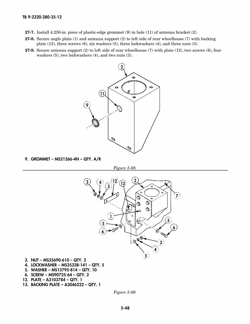
3. NUT – MS35690-610 – QTY. 24. LOCKWASHER – MS35338-141 – QTY. 55. WASHER – MS15795-814 – QTY. 106. SCREW – MS90725-64 – QTY. 2
12. PLATE – A3103784 – QTY. 113. BACKING PLATE – A3046222 – QTY. 1
27-7. Install 4.250-in. piece of plastic-edge grommet (9) in hole (11) of antenna bracket (2).
27-8. Secure angle plate (1) and antenna support (2) to left side of rear wheelhouse (7) with backingplate (13), three screws (6), six washers (5), three lockwashers (4), and three nuts (3).
27-9. Secure antenna support (2) to left side of rear wheelhouse (7) with plate (12), two screws (6), fourwashers (5), two lockwashers (4), and two nuts (3).
Figure 5-68.
Figure 5-69.
4 2
2
35
55
9
11
12
1
7
13
66
~
~~
43
5
9. GROMMET – MS21266-4N – QTY. A/R
TB 9-2320-280-35-12
5-49
Figure 5-70.
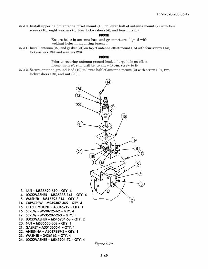
27-10. Install upper half of antenna offset mount (15) on lower half of antenna mount (2) with four screws (16), eight washers (5), four lockwashers (4), and four nuts (3).
NNOOTTEEEnsure holes in antenna base and grommet are aligned withweldnut holes in mounting bracket.
27-11. Install antenna (22) and gasket (21) on top of antenna offset mount (15) with four screws (14),lockwashers (24), and washers (23).
NNOOTTEEPrior to securing antenna ground lead, enlarge hole on offsetmount with 9/32-in. drill bit to allow 1/4-in. screw to fit.
27-12. Secure antenna ground lead (19) to lower half of antenna mount (2) with screw (17), twolockwashers (18), and nut (20).
15
22
14
17
18
18
19
20
21
23
24
5
5
4
3
2
16
~
3. NUT – MS35690-610 – QTY. 44. LOCKWASHER – MS35338-141 – QTY. 45. WASHER – MS15795-814 – QTY. 8
14. CAPSCREW – MS35307-365 – QTY. 415. OFFSET MOUNT – A3046219 – QTY. 116. SCREW – MS90725-62 – QTY. 417. SCREW – MS35207-263 – QTY. 118. LOCKWASHER – MS45904-68 – QTY. 220. NUT – MS35650-302 – QTY. 121. GASKET – A3013655-1 – QTY. 122. ANTENNA – A3017889-2 – QTY. 123. WASHER – 2436163 – QTY. 424. LOCKWASHER – MS45904-72 – QTY. 4

TB 9-2320-280-35-12
5-50
27-13. Attach upper antenna element (25) to lower antenna element (27).27-14. Attach antenna assembly to antenna base (22).27-15. Attach fiber rope assembly (26) to upper antenna element (25).27-16. Secure lower antenna element (27) to antenna base (22) with lockwire (28).
Figure 5-71.
25
27 28
22
26
27
22
25. UPPER ANTENNA ELEMENT – A3017901-2 – QTY. 126. FIBER ROPE ASSEMBLY – A3167672-1 – QTY. 127. LOWER ANTENNA ELEMENT – A3018230-1 – QTY. 128. LOCKWIRE – MS20995C32 – QTY. A/R
TB 9-2320-280-35-12
5-51
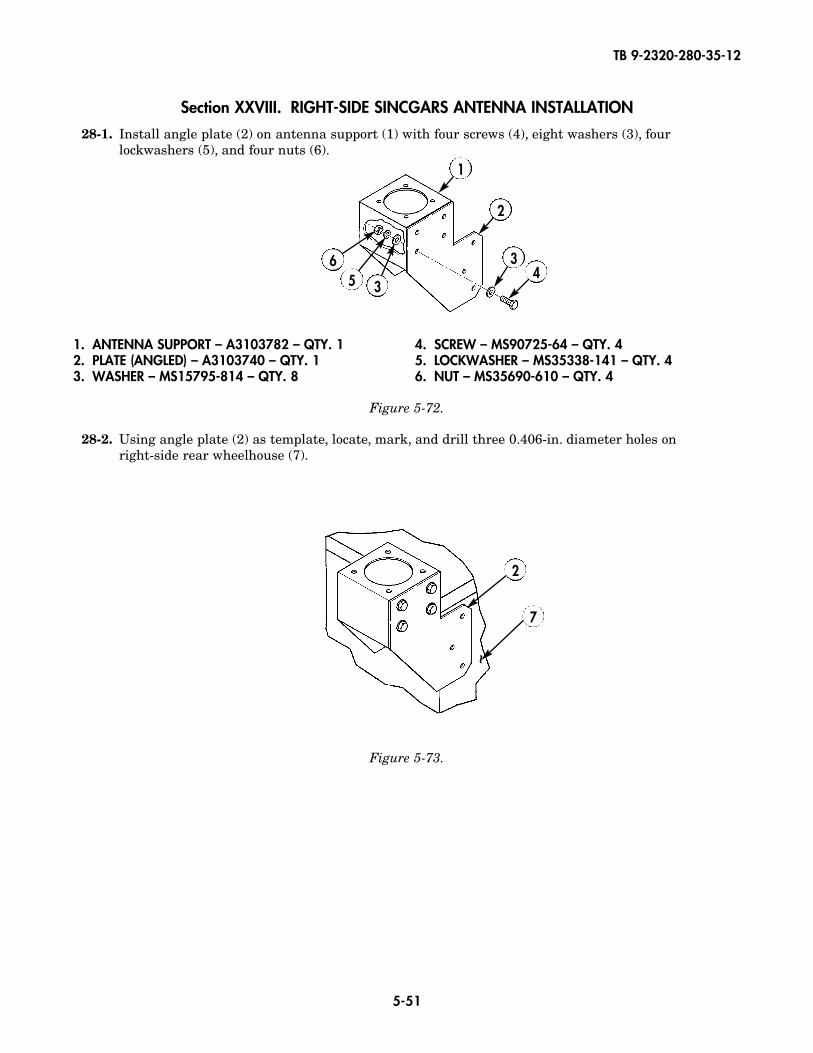
1. ANTENNA SUPPORT – A3103782 – QTY. 12. PLATE (ANGLED) – A3103740 – QTY. 13. WASHER – MS15795-814 – QTY. 8
4. SCREW – MS90725-64 – QTY. 45. LOCKWASHER – MS35338-141 – QTY. 46. NUT – MS35690-610 – QTY. 4
Figure 5-73.
Figure 5-72.
Section XXVIII. RIGHT-SIDE SINCGARS ANTENNA INSTALLATION
28-1. Install angle plate (2) on antenna support (1) with four screws (4), eight washers (3), fourlockwashers (5), and four nuts (6).
28-2. Using angle plate (2) as template, locate, mark, and drill three 0.406-in. diameter holes on right-side rear wheelhouse (7).
1
2
2
7
34
356
~
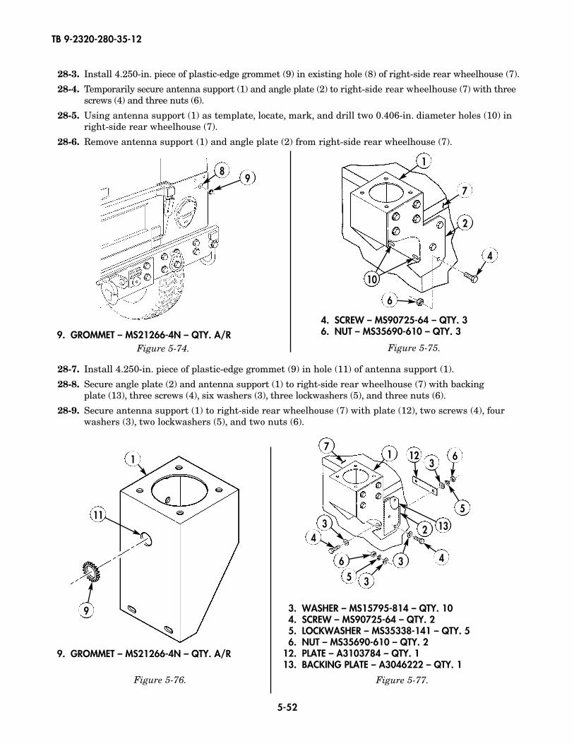
TB 9-2320-280-35-12
5-52
28-3. Install 4.250-in. piece of plastic-edge grommet (9) in existing hole (8) of right-side rear wheelhouse (7).
28-4. Temporarily secure antenna support (1) and angle plate (2) to right-side rear wheelhouse (7) with threescrews (4) and three nuts (6).
28-5. Using antenna support (1) as template, locate, mark, and drill two 0.406-in. diameter holes (10) inright-side rear wheelhouse (7).
28-6. Remove antenna support (1) and angle plate (2) from right-side rear wheelhouse (7).
28-7. Install 4.250-in. piece of plastic-edge grommet (9) in hole (11) of antenna support (1).
28-8. Secure angle plate (2) and antenna support (1) to right-side rear wheelhouse (7) with backingplate (13), three screws (4), six washers (3), three lockwashers (5), and three nuts (6).
28-9. Secure antenna support (1) to right-side rear wheelhouse (7) with plate (12), two screws (4), fourwashers (3), two lockwashers (5), and two nuts (6).
4. SCREW – MS90725-64 – QTY. 36. NUT – MS35690-610 – QTY. 3
3. WASHER – MS15795-814 – QTY. 104. SCREW – MS90725-64 – QTY. 25. LOCKWASHER – MS35338-141 – QTY. 56. NUT – MS35690-610 – QTY. 2
12. PLATE – A3103784 – QTY. 113. BACKING PLATE – A3046222 – QTY. 1
Figure 5-75.Figure 5-74.
7
18
9
2
4
6
10
Figure 5-76.
1
11
9
Figure 5-77.
5
2 13
3
356
34
4
1 123
76
~
~
9. GROMMET – MS21266-4N – QTY. A/R
9. GROMMET – MS21266-4N – QTY. A/R

TB 9-2320-280-35-12
5-53
28-10. Install upper half of antenna offset mount (18) to antenna support (1) with four screws (23), eightwashers (3), four lockwashers (5), and four nuts (6).
NNOOTTEEEnsure holes in antenna base are aligned with weldnut holes inmounting bracket.
28-11. Install antenna (24) and gasket (17) on antenna offset mount (18) and secure with four screws (14), lockwashers (15), and washers (16).
NNOOTTEEPrior to securing antenna ground lead, enlarge hole on offsetmount with 9/32-in. drill bit to allow 1/4-in. screw to fit.
28-12. Secure antenna ground lead (20) to antenna offset mount (18) with screw (22), two lockwashers (21), and nut (19).
14
15
16
18
17
19
2021
21
1
22
6
5
3
3
23
24
~
3. WASHER – MS15795-814 – QTY. 85. LOCKWASHER – MS35338-141 – QTY. 46. NUT – MS35690-610 – QTY. 4
14. CAPSCREW – MS35307-365 – QTY. 415. LOCKWASHER – MS45904-72 – QTY. 416. WASHER – 2436163 – QTY. 817. GASKET – A3013655-1 – QTY. 1
18. OFFSET MOUNT – A3046219 – QTY. 119. NUT – MS35650-302 – QTY. 121. LOCKWASHER – MS45904-68 – QTY. 222. SCREW – MS35207-263 – QTY. 123. SCREW – MS90725-62 – QTY. 424. ANTENNA – A3017899-2 – QTY. 1
Figure 5-78.
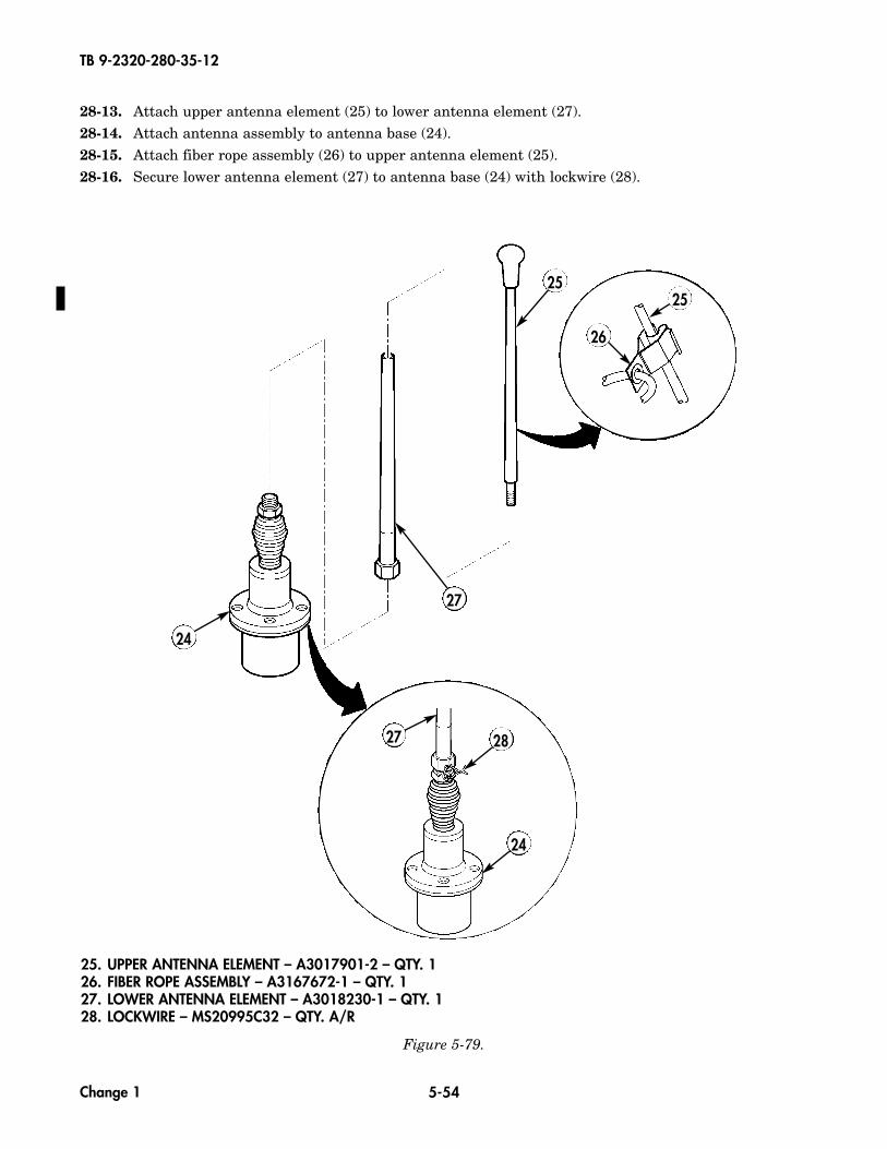
TB 9-2320-280-35-12
5-54
28-13. Attach upper antenna element (25) to lower antenna element (27).28-14. Attach antenna assembly to antenna base (24).28-15. Attach fiber rope assembly (26) to upper antenna element (25).28-16. Secure lower antenna element (27) to antenna base (24) with lockwire (28).
25
27 28
24
26
27
24
25. UPPER ANTENNA ELEMENT – A3017901-2 – QTY. 126. FIBER ROPE ASSEMBLY – A3167672-1 – QTY. 127. LOWER ANTENNA ELEMENT – A3018230-1 – QTY. 128. LOCKWIRE – MS20995C32 – QTY. A/R
Figure 5-79.
Change 1
25
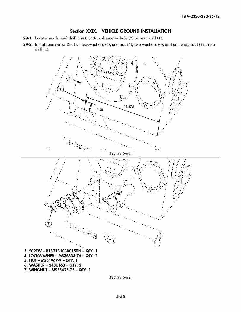
TB 9-2320-280-35-12
5-55
3. SCREW – B1821BH038C150N – QTY. 14. LOCKWASHER – MS35333-76 – QTY. 25. NUT – MS51967-9 – QTY. 16. WASHER – 2436163 – QTY. 27. WINGNUT – MS35425-75 – QTY. 1
Section XXIX. VEHICLE GROUND INSTALLATION29-1. Locate, mark, and drill one 0.343-in. diameter hole (2) in rear wall (1).
29-2. Install one screw (3), two lockwashers (4), one nut (5), two washers (6), and one wingnut (7) in rearwall (1).
1
2
Figure 5-80.
Figure 5-81.
3.5011.875
~
45
7
34
6
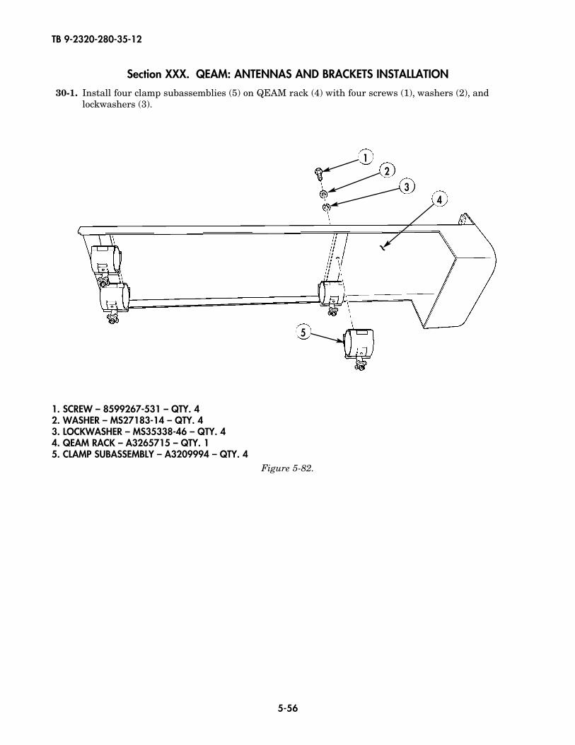
TB 9-2320-280-35-12
5-56
Section XXX. QEAM: ANTENNAS AND BRACKETS INSTALLATION
30-1. Install four clamp subassemblies (5) on QEAM rack (4) with four screws (1), washers (2), andlockwashers (3).
Figure 5-82.
12
34
5
~
1. SCREW – 8599267-531 – QTY. 42. WASHER – MS27183-14 – QTY. 43. LOCKWASHER – MS35338-46 – QTY. 44. QEAM RACK – A3265715 – QTY. 15. CLAMP SUBASSEMBLY – A3209994 – QTY. 4

TB 9-2320-280-35-12
5-57
Figure 5-83.
~
30-2. Using QEAM rack (4) as template, locate, mark, and drill four 0.344-in. diameter holes (9) in roof ofvehicle (14).
30-3. Mark location for four QEAM spacers (8) and apply RTV sealant to marked areas (10).NOTE
Allow RTV to cure for 30 minutes.30-4. Press four spacers (8) onto roof of vehicle (14).
30-5. Position QEAM rack (4) over holes in four spacers (8).
30-6. Apply RTV to four bolt holes (9) and insert four bolts (6) and washers (7) into QEAM carrier.
30-7. Apply RTV to one side of four washers (11). Press washers (11) in place.
30-8. Install lockwasher (12) and nut (13).
6 74
8
9
10
11
12
13
14
6. SCREW – B1821BH031C300N – QTY. 47. WASHER – 120393 – QTY. 48. QEAM SPACER (PART OF A3265715) – QTY. 4
11. WASHER – 120393 – QTY. 412. LOCKWASHER – MS45904-72 – QTY. 413. NUT – MS51967-6 – QTY. 4
~
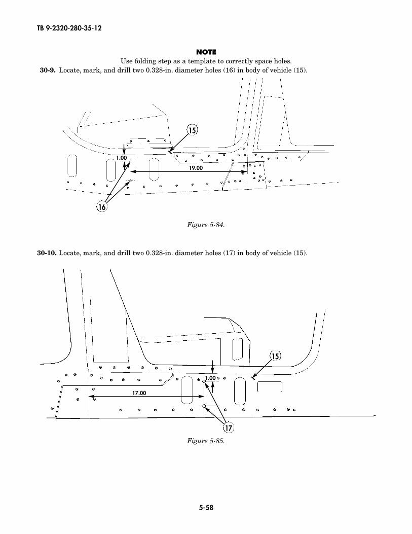
TB 9-2320-280-35-12
5-58
Figure 5-85.
Figure 5-84.
30-10. Locate, mark, and drill two 0.328-in. diameter holes (17) in body of vehicle (15).
NOTEUse folding step as a template to correctly space holes.
30-9. Locate, mark, and drill two 0.328-in. diameter holes (16) in body of vehicle (15).
15
~~
19.00
1.00
17.00
1.00
17
16
15
~~
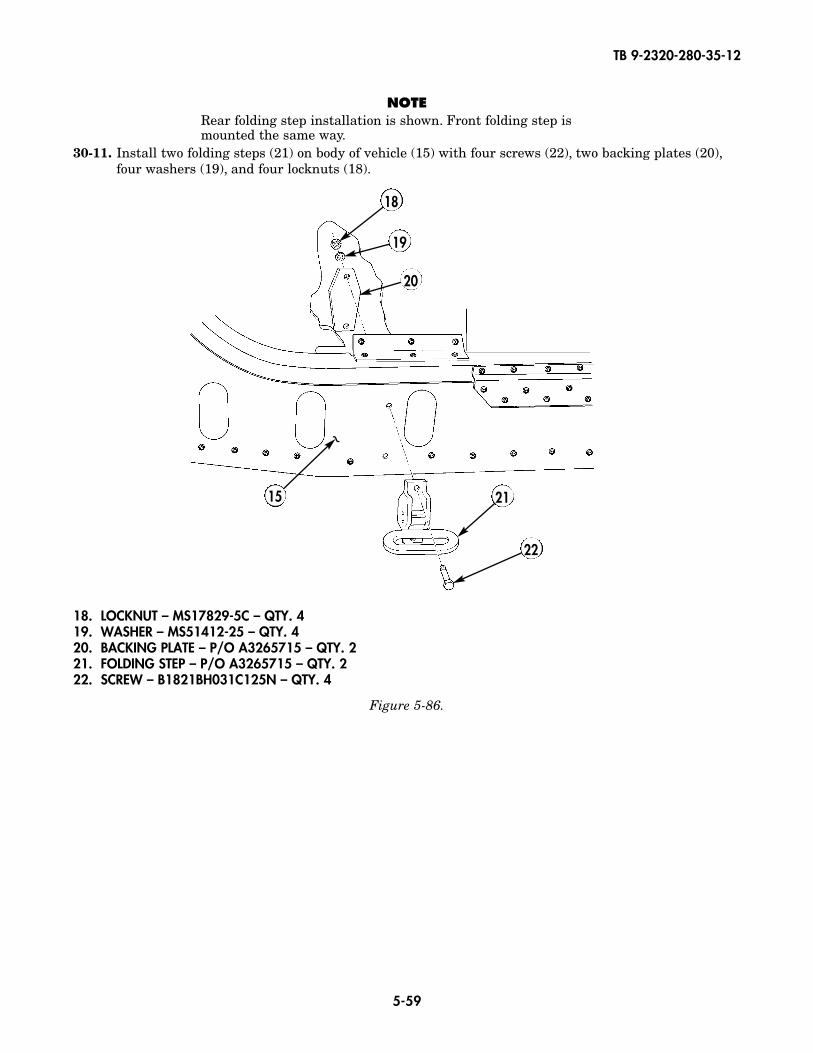
TB 9-2320-280-35-12
5-59
NOTERear folding step installation is shown. Front folding step ismounted the same way.
30-11. Install two folding steps (21) on body of vehicle (15) with four screws (22), two backing plates (20),four washers (19), and four locknuts (18).
21
20
19
18
22
18. LOCKNUT – MS17829-5C – QTY. 419. WASHER – MS51412-25 – QTY. 420. BACKING PLATE – P/O A3265715 – QTY. 221. FOLDING STEP – P/O A3265715 – QTY. 222. SCREW – B1821BH031C125N – QTY. 4
Figure 5-86.
~15
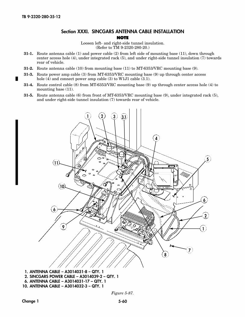
TB 9-2320-280-35-12
5-60
Section XXXI. SINCGARS ANTENNA CABLE INSTALLATIONNNOOTTEE
Loosen left- and right-side tunnel insulation.(Refer to TM 9-2320-280-20.)
31-1. Route antenna cable (1) and power cable (2) from left side of mounting base (11), down throughcenter access hole (4), under integrated rack (5), and under right-side tunnel insulation (7) towardsrear of vehicle.
31-2. Route antenna cable (10) from mounting base (11) to MT-6353/VRC mounting base (9).31-3. Route power amp cable (3) from MT-6353/VRC mounting base (9) up through center access
hole (4) and connect power amp cable (3) to W1J1 cable (3.1).31-4. Route control cable (8) from MT-6353/VRC mounting base (9) up through center access hole (4) to
mounting base (11).31-5. Route antenna cable (6) from front of MT-6353/VRC mounting base (9), under integrated rack (5),
and under right-side tunnel insulation (7) towards rear of vehicle.
1
8
11
4
10
6
9
32
5
1
2
7
6~
~
~
~
1. ANTENNA CABLE – A3014031-8 – QTY. 12. SINCGARS POWER CABLE – A3014039-2 – QTY. 16. ANTENNA CABLE – A3014031-17 – QTY. 1
10. ANTENNA CABLE – A3014032-3 – QTY. 1
Figure 5-87.
Change 1
3.1
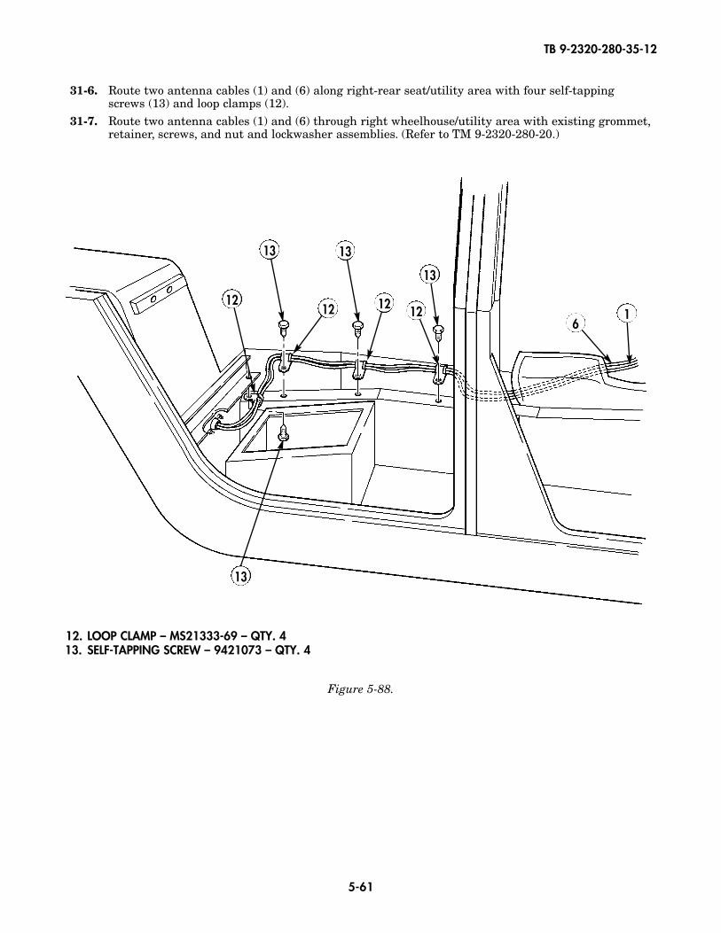
TB 9-2320-280-35-12
5-61
Figure 5-88.
31-6. Route two antenna cables (1) and (6) along right-rear seat/utility area with four self-tapping screws (13) and loop clamps (12).
31-7. Route two antenna cables (1) and (6) through right wheelhouse/utility area with existing grommet,retainer, screws, and nut and lockwasher assemblies. (Refer to TM 9-2320-280-20.)
12. LOOP CLAMP – MS21333-69 – QTY. 413. SELF-TAPPING SCREW – 9421073 – QTY. 4
12 12 12
13
13
13
12
13
61

TB 9-2320-280-35-12
5-62
Figure 5-89.
12. LOOP CLAMP – MS21333-69 – QTY. 313. SELF-TAPPING SCREW – 9421073 – QTY. 215. NUT – MS35650-302 – QTY. 117. SCREW – MS35224-65 – QTY. 124. TIE STRAP – MS3367-1-0 – QTY. A/R29. SCREW – MS90725-30 – QTY. 430. WASHER – MS27183-12 – QTY. 4
27
6
28
29
3132
353433
1415
16
17
12
1819
2021
2223
24
18
2518
25
261
30
13
31-8. Route two antenna cables (1) and (6) along front wheelwell seam (16) and along front (14),intermediate (35), and rear (33) cargo bed supports. Secure with two self-tapping screws (13), loopclamps (12), screw (17), loop clamp (12), nut (15), and existing self-tapping screw (18) and loopclamp (33).
31-9. Route antenna cable (1) along existing taillight wiring harness (44) with two existing loop clamps(27) and (26), self-tapping screws (18), and lockwashers (25).
31-10. Route antenna cable (1) to antenna base (32) with existing loop clamp (19), nut (23), lockwasher (22),washer (21), and screw (20).
31-11. Attach antenna cable (1) to antenna base (32).31-12. Coil excess antenna cable (1) and secure to inside of taillight closeout cover with tiedown strap (24).31-13. Attach cover plate (31) to offset antenna mount (28) with four screws (29) and four washers (30).
12
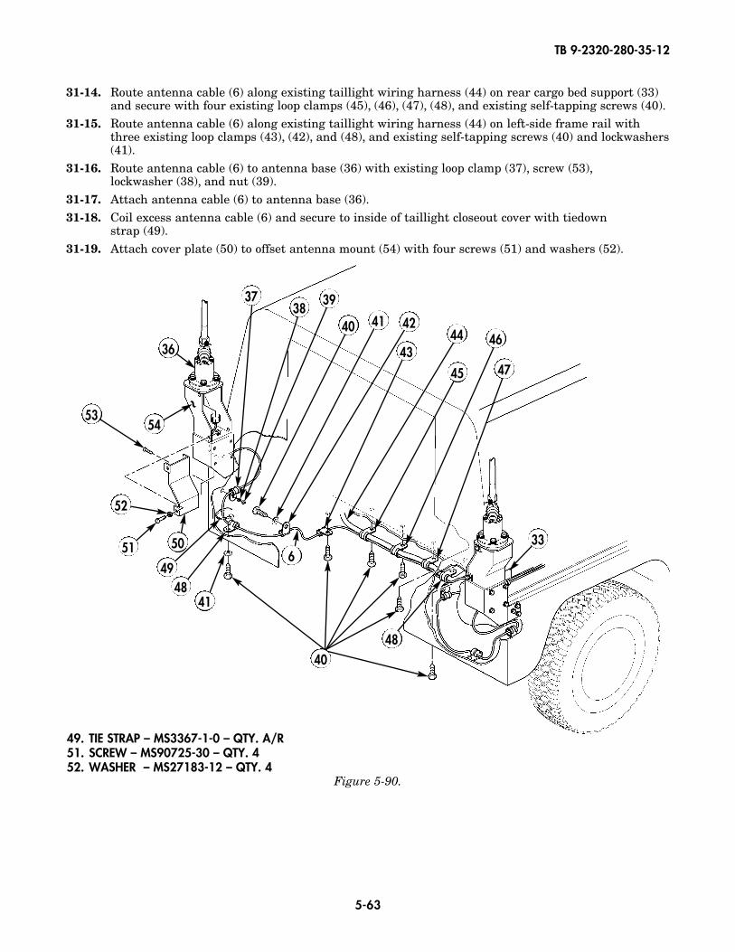
TB 9-2320-280-35-12
5-63
49. TIE STRAP – MS3367-1-0 – QTY. A/R51. SCREW – MS90725-30 – QTY. 452. WASHER – MS27183-12 – QTY. 4
31-14. Route antenna cable (6) along existing taillight wiring harness (44) on rear cargo bed support (33)and secure with four existing loop clamps (45), (46), (47), (48), and existing self-tapping screws (40).
31-15. Route antenna cable (6) along existing taillight wiring harness (44) on left-side frame rail withthree existing loop clamps (43), (42), and (48), and existing self-tapping screws (40) and lockwashers(41).
31-16. Route antenna cable (6) to antenna base (36) with existing loop clamp (37), screw (53),lockwasher (38), and nut (39).
31-17. Attach antenna cable (6) to antenna base (36).31-18. Coil excess antenna cable (6) and secure to inside of taillight closeout cover with tiedown
strap (49).31-19. Attach cover plate (50) to offset antenna mount (54) with four screws (51) and washers (52).
Figure 5-90.
36
3738
39
40 41 42
43
45
44 46
47
6
48
33
4148
5149
50
52
40
5354
~

TB 9-2320-280-35-12
5-64
1. INC-EPUU CABLE – A3279383-3 – QTY. 13. PLGR-POWER CABLE – 9728558-10 – QTY. 4
Figure 5-91.
Section XXXII. PLGR POWER CABLE INSTALLATION32-1. Route INC-EPUU cable (1) from mounting base (5), through access hole (2), under right-side tunnel
insulation (4), to rear battery box.
32-2. Route PLGR power cable (3) under right-side tunnel insulation (4) to rear battery box.
5
1
2
3
4
~
~

TB 9-2320-280-35-12
5-65
Section XXXIII. LEFT-SIDE EPLRS ANTENNA CABLE INSTALLATION33-1. Connect EPLRS antenna cable (2) to EPLRS antenna (1).33-2. Route EPLRS antenna cable (2) through hole in bracket (3) and fiberglass body (4). Secure with
clamp (6) and self-tapping screw (5).
Figure 5-92.
Figure 5-93.
2. EPLRS ANTENNA CABLE – SM-C-911480 – QTY. 1
5. SELF-TAPPING SCREW – 9421073 – QTY. 16. LOOP CLAMP – MS21333-71 – QTY. 1
~
~
2
3
1
4
45
6
2

TB 9-2320-280-35-12
5-66
Figure 5-94.
5. SELF-TAPPING SCREW – 9421073 – QTY. 16. LOOP CLAMP – MS21333-71 – QTY. 1
33-3. Route EPLRS antenna cable (2) to C-pillar (7) and secure with clamp (6) and self-tapping screw (5).
~6
7
5
2
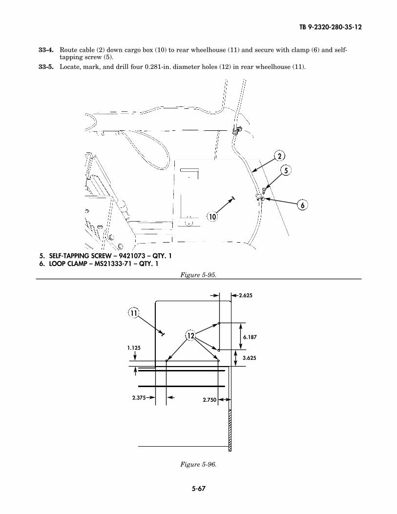
TB 9-2320-280-35-12
5-67
33-4. Route cable (2) down cargo box (10) to rear wheelhouse (11) and secure with clamp (6) and self-tapping screw (5).
33-5. Locate, mark, and drill four 0.281-in. diameter holes (12) in rear wheelhouse (11).
~
~
6
5
2
10
5. SELF-TAPPING SCREW – 9421073 – QTY. 16. LOOP CLAMP – MS21333-71 – QTY. 1
Figure 5-95.
11
2.625
6.187
3.625
2.7502.375
1.125
12
Figure 5-96.
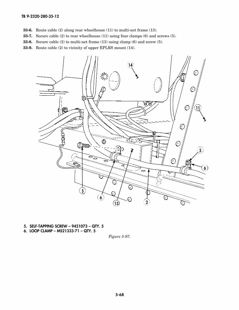
TB 9-2320-280-35-12
5-68
5. SELF-TAPPING SCREW – 9421073 – QTY. 56. LOOP CLAMP – MS21333-71 – QTY. 5
33-6. Route cable (2) along rear wheelhouse (11) to multi-net frame (13).33-7. Secure cable (2) to rear wheelhouse (11) using four clamps (6) and screws (5).33-8. Secure cable (2) to multi-net frame (13) using clamp (6) and screw (5).33-9. Route cable (2) to vicinity of upper EPLRS mount (14).
~
6
62
5
5
14
~
11
~
13
Figure 5-97.
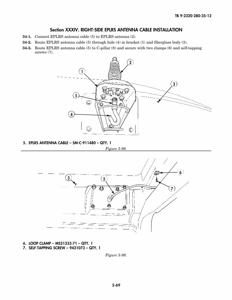
TB 9-2320-280-35-12
5-69
Section XXXIV. RIGHT-SIDE EPLRS ANTENNA CABLE INSTALLATION34-1. Connect EPLRS antenna cable (5) to EPLRS antenna (2).34-2. Route EPLRS antenna cable (5) through hole (4) in bracket (1) and fiberglass body (3).34-3. Route EPLRS antenna cable (5) to C-pillar (8) and secure with two clamps (6) and self-tapping
screws (7).
5. EPLRS ANTENNA CABLE – SM-C-911480 – QTY. 1Figure 5-98.
~
3
4
2
5
1
3
7
65
Figure 5-99.
~
6. LOOP CLAMP – MS21333-71 – QTY. 17. SELF-TAPPING SCREW – 9421073 – QTY. 1
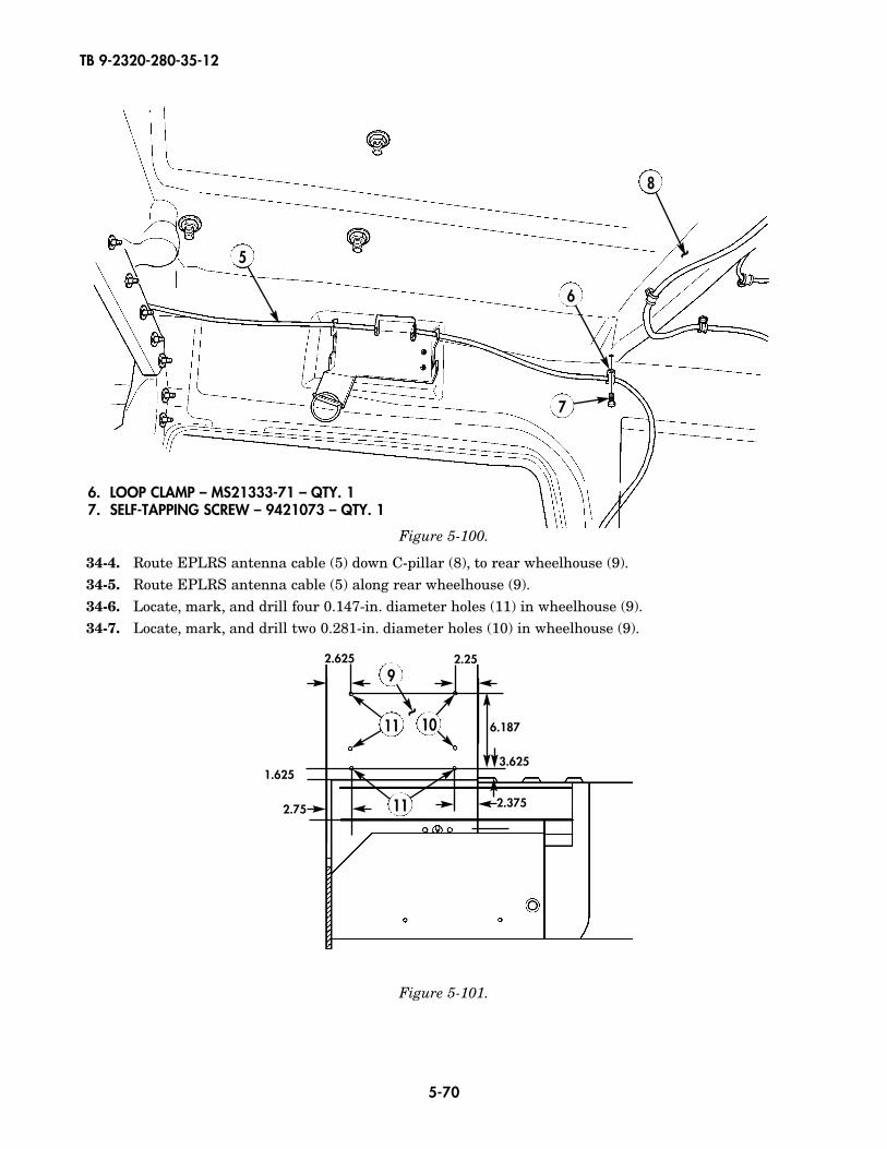
TB 9-2320-280-35-12
5-70
Figure 5-100.
Figure 5-101.
34-4. Route EPLRS antenna cable (5) down C-pillar (8), to rear wheelhouse (9).34-5. Route EPLRS antenna cable (5) along rear wheelhouse (9).34-6. Locate, mark, and drill four 0.147-in. diameter holes (11) in wheelhouse (9).34-7. Locate, mark, and drill two 0.281-in. diameter holes (10) in wheelhouse (9).
~
8
7
6
5
92.625
2.3752.75
1.6253.625
2.25
6.187
11
11 10~
6. LOOP CLAMP – MS21333-71 – QTY. 17. SELF-TAPPING SCREW – 9421073 – QTY. 1
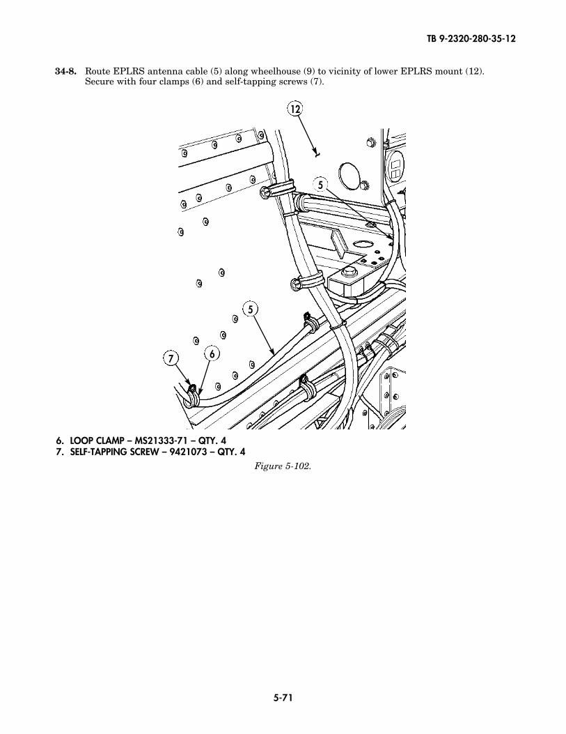
TB 9-2320-280-35-12
5-71
34-8. Route EPLRS antenna cable (5) along wheelhouse (9) to vicinity of lower EPLRS mount (12).Secure with four clamps (6) and self-tapping screws (7).
~
12
7
5
5
6
6. LOOP CLAMP – MS21333-71 – QTY. 47. SELF-TAPPING SCREW – 9421073 – QTY. 4
Figure 5-102.
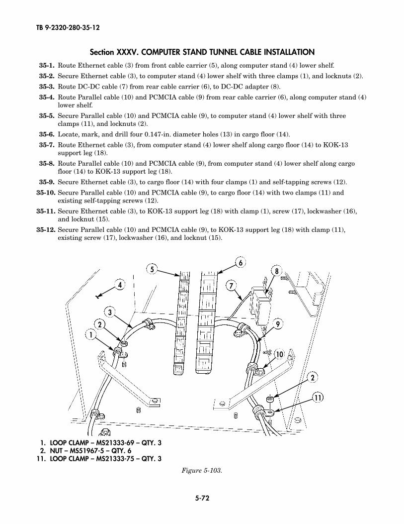
TB 9-2320-280-35-12
5-72
Section XXXV. COMPUTER STAND TUNNEL CABLE INSTALLATION
35-1. Route Ethernet cable (3) from front cable carrier (5), along computer stand (4) lower shelf.
35-2. Secure Ethernet cable (3), to computer stand (4) lower shelf with three clamps (1), and locknuts (2).
35-3. Route DC-DC cable (7) from rear cable carrier (6), to DC-DC adapter (8).
35-4. Route Parallel cable (10) and PCMCIA cable (9) from rear cable carrier (6), along computer stand (4)lower shelf.
35-5. Secure Parallel cable (10) and PCMCIA cable (9), to computer stand (4) lower shelf with threeclamps (11), and locknuts (2).
35-6. Locate, mark, and drill four 0.147-in. diameter holes (13) in cargo floor (14).
35-7. Route Ethernet cable (3), from computer stand (4) lower shelf along cargo floor (14) to KOK-13support leg (18).
35-8. Route Parallel cable (10) and PCMCIA cable (9), from computer stand (4) lower shelf along cargofloor (14) to KOK-13 support leg (18).
35-9. Secure Ethernet cable (3), to cargo floor (14) with four clamps (1) and self-tapping screws (12).
35-10. Secure Parallel cable (10) and PCMCIA cable (9), to cargo floor (14) with two clamps (11) andexisting self-tapping screws (12).
35-11. Secure Ethernet cable (3), to KOK-13 support leg (18) with clamp (1), screw (17), lockwasher (16),and locknut (15).
35-12. Secure Parallel cable (10) and PCMCIA cable (9), to KOK-13 support leg (18) with clamp (11),existing screw (17), lockwasher (16), and locknut (15).
~
12
3
4
56
7
8
9
10
2
11
1. LOOP CLAMP – MS21333-69 – QTY. 32. NUT – MS51967-5 – QTY. 6
11. LOOP CLAMP – MS21333-75 – QTY. 3
Figure 5-103.
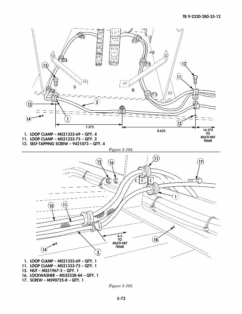
TB 9-2320-280-35-12
5-73
1. LOOP CLAMP – MS21333-69 – QTY. 411. LOOP CLAMP – MS21333-75 – QTY. 212. SELF-TAPPING SCREW – 9421073 – QTY. 4
Figure 5-104.
12 12
11
13
1314 1
3
8.625 14.375TO
MULTI-NETFRAME
7.375
15
14
16
1110
11
1
17
3
18~
~
6.5TO
MULTI-NETFRAME
1. LOOP CLAMP – MS21333-69 – QTY. 111. LOOP CLAMP – MS21333-75 – QTY. 115. NUT – MS51967-2 – QTY. 116. LOCKWASHER – MS35338-44 – QTY. 117. SCREW – MS90725-8 – QTY. 1
Figure 5-105.
~
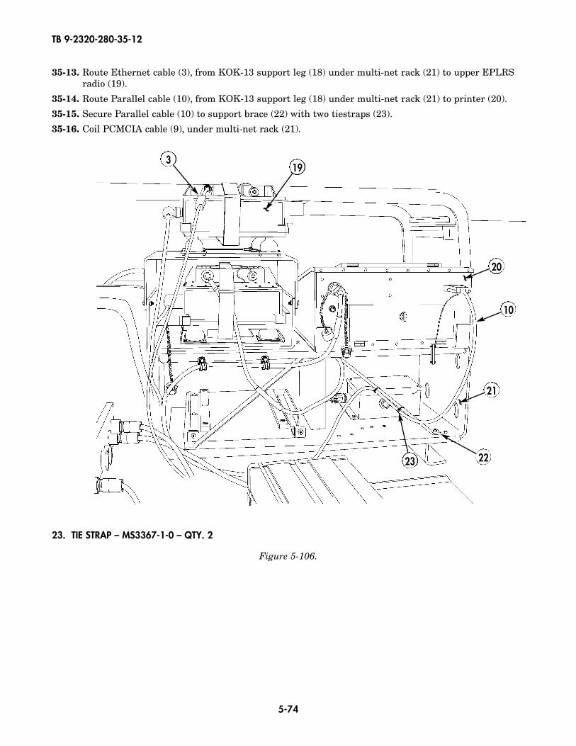
TB 9-2320-280-35-12
5-74
35-13. Route Ethernet cable (3), from KOK-13 support leg (18) under multi-net rack (21) to upper EPLRSradio (19).
35-14. Route Parallel cable (10), from KOK-13 support leg (18) under multi-net rack (21) to printer (20).
35-15. Secure Parallel cable (10) to support brace (22) with two tiestraps (23).
35-16. Coil PCMCIA cable (9), under multi-net rack (21).
319
20
10
~
~
21
2223
~
23. TIE STRAP – MS3367-1-0 – QTY. 2
Figure 5-106.
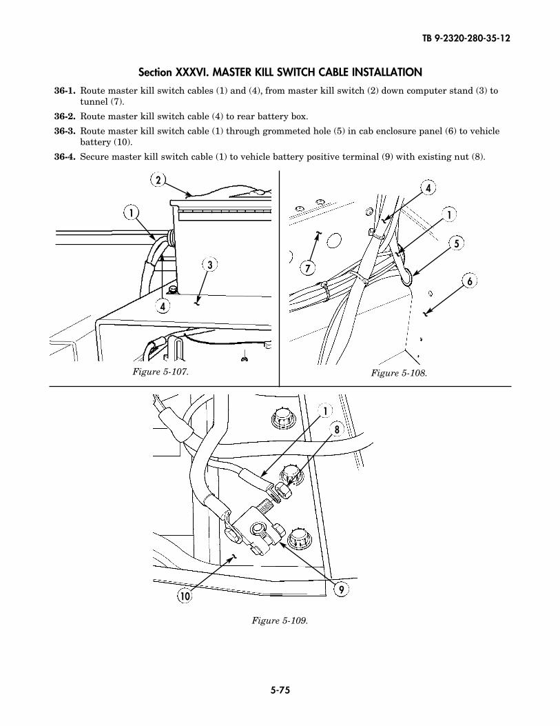
TB 9-2320-280-35-12
5-75
Figure 5-107. Figure 5-108.
Figure 5-109.
Section XXXVI. MASTER KILL SWITCH CABLE INSTALLATION
36-1. Route master kill switch cables (1) and (4), from master kill switch (2) down computer stand (3) totunnel (7).
36-2. Route master kill switch cable (4) to rear battery box.
36-3. Route master kill switch cable (1) through grommeted hole (5) in cab enclosure panel (6) to vehiclebattery (10).
36-4. Secure master kill switch cable (1) to vehicle battery positive terminal (9) with existing nut (8).
3 7
4
5
1
2
4 ~
~
6
~
1
10
8
9
~
1
~~
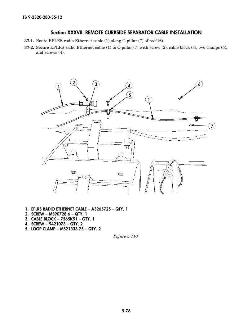
TB 9-2320-280-35-12
5-76
Section XXXVII. REMOTE CURBSIDE SEPARATOR CABLE INSTALLATION
37-1. Route EPLRS radio Ethernet cable (1) along C-pillar (7) of roof (6).
37-2. Secure EPLRS radio Ethernet cable (1) to C-pillar (7) with screw (2), cable block (3), two clamps (5),and screws (4).
42 3
5
6
~
7
~
1
1
1. EPLRS RADIO ETHERNET CABLE – A3265725 – QTY. 12. SCREW – MS90728-6 – QTY. 13. CABLE BLOCK – 7565K51 – QTY. 14. SCREW – 9421073 – QTY. 25. LOOP CLAMP – MS21333-75 – QTY. 2
Figure 5-110.
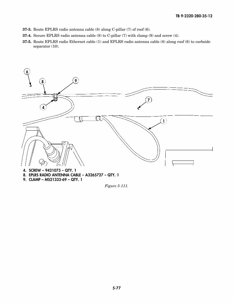
TB 9-2320-280-35-12
5-77
37-3. Route EPLRS radio antenna cable (8) along C-pillar (7) of roof (6).
37-4. Secure EPLRS radio antenna cable (8) to C-pillar (7) with clamp (9) and screw (4).
37-5. Route EPLRS radio Ethernet cable (1) and EPLRS radio antenna cable (8) along roof (6) to curbsideseparator (10).
4. SCREW – 9421073 – QTY. 18. EPLRS RADIO ANTENNA CABLE – A3265727 – QTY. 19. CLAMP – MS21333-69 – QTY. 1
Figure 5-111.
9
4
8
6
7
1
~
~
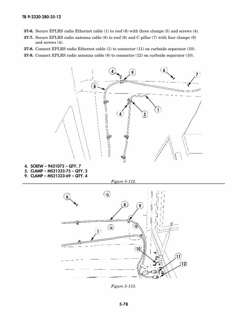
TB 9-2320-280-35-12
5-78
37-6. Secure EPLRS radio Ethernet cable (1) to roof (6) with three clamps (5) and screws (4).
37-7. Secure EPLRS radio antenna cable (8) to roof (6) and C pillar (7) with four clamps (9) and screws (4).
37-8. Connect EPLRS radio Ethernet cable (1) to connector (11) on curbside separator (10).
37-9. Connect EPLRS radio antenna cable (8) to connector (12) on curbside separator (10).
9
154
4
8
67
~~
4. SCREW – 9421073 – QTY. 75. CLAMP – MS21333-75 – QTY. 39. CLAMP – MS21333-69 – QTY. 4
Figure 5-112.
Figure 5-113.
8 9
1
6
~
10
11
12~
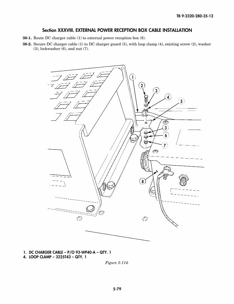
TB 9-2320-280-35-12
5-79
1. DC CHARGER CABLE – P/O 93-WP40-A – QTY. 14. LOOP CLAMP – 3225T43 – QTY. 1
Figure 5-114.
Section XXXVIII. EXTERNAL POWER RECEPTION BOX CABLE INSTALLATION
38-1. Route DC charger cable (1) to external power reception box (8).
38-2. Secure DC charger cable (1) to DC charger guard (5), with loop clamp (4), existing screw (2), washer(3), lockwasher (6), and nut (7).
23
3
45
1
8
6
7
~
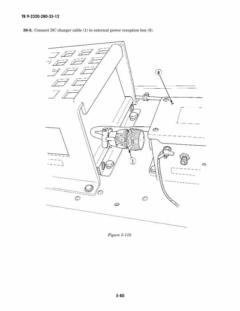
TB 9-2320-280-35-12
5-80
38-3. Connect DC charger cable (1) to external power reception box (8).
8
1
~
Figure 5-115.
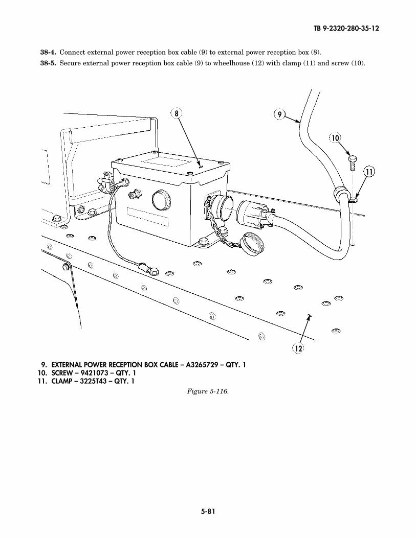
TB 9-2320-280-35-12
5-81
38-4. Connect external power reception box cable (9) to external power reception box (8).
38-5. Secure external power reception box cable (9) to wheelhouse (12) with clamp (11) and screw (10).
8
~
12
~
Figure 5-116.
9
10
11
9. EXTERNAL POWER RECEPTION BOX CABLE – A3265729 – QTY. 110. SCREW – 9421073 – QTY. 111. CLAMP – 3225T43 – QTY. 1
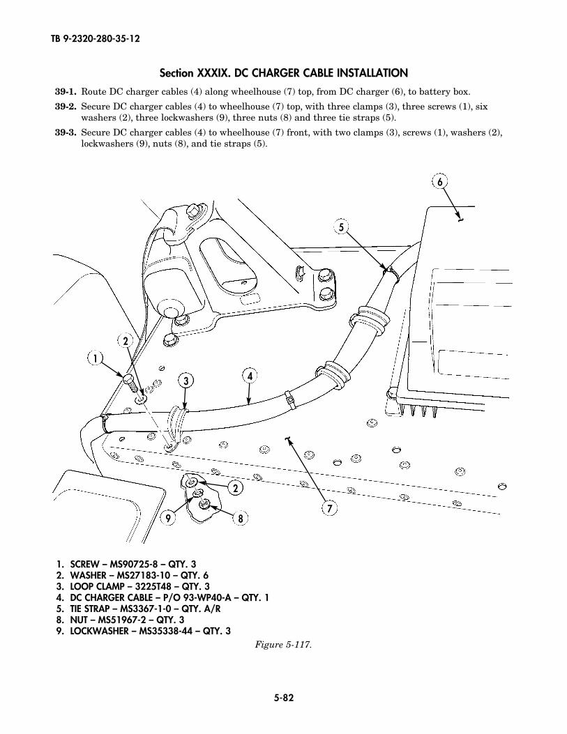
TB 9-2320-280-35-12
5-82
Section XXXIX. DC CHARGER CABLE INSTALLATION
39-1. Route DC charger cables (4) along wheelhouse (7) top, from DC charger (6), to battery box.
39-2. Secure DC charger cables (4) to wheelhouse (7) top, with three clamps (3), three screws (1), sixwashers (2), three lockwashers (9), three nuts (8) and three tie straps (5).
39-3. Secure DC charger cables (4) to wheelhouse (7) front, with two clamps (3), screws (1), washers (2),lockwashers (9), nuts (8), and tie straps (5).
5
6
1
2
3 4
2
9 8
~
7
~
1. SCREW – MS90725-8 – QTY. 32. WASHER – MS27183-10 – QTY. 63. LOOP CLAMP – 3225T48 – QTY. 34. DC CHARGER CABLE – P/O 93-WP40-A – QTY. 15. TIE STRAP – MS3367-1-0 – QTY. A/R8. NUT – MS51967-2 – QTY. 39. LOCKWASHER – MS35338-44 – QTY. 3
Figure 5-117.
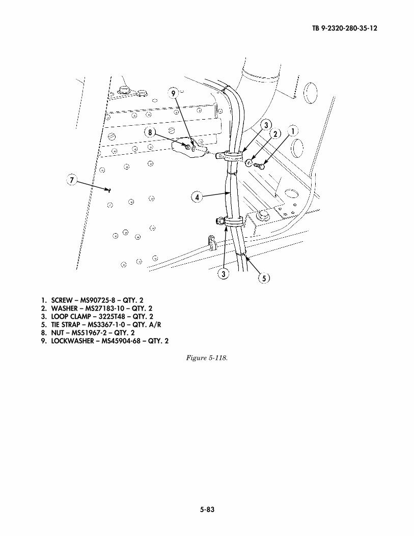
TB 9-2320-280-35-12
5-83
1. SCREW – MS90725-8 – QTY. 22. WASHER – MS27183-10 – QTY. 23. LOOP CLAMP – 3225T48 – QTY. 25. TIE STRAP – MS3367-1-0 – QTY. A/R8. NUT – MS51967-2 – QTY. 29. LOCKWASHER – MS45904-68 – QTY. 2
Figure 5-118.
9
32 1
3 5
4
7
8
~
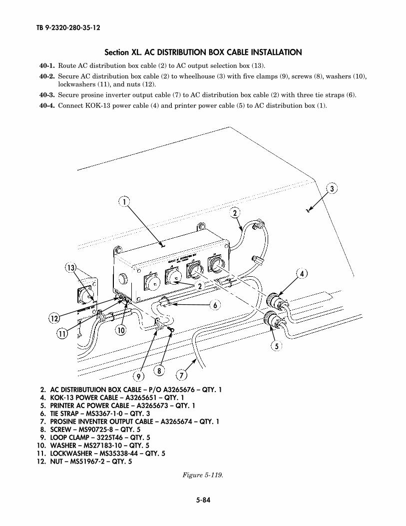
TB 9-2320-280-35-12
5-84
Section XL. AC DISTRIBUTION BOX CABLE INSTALLATION
40-1. Route AC distribution box cable (2) to AC output selection box (13).
40-2. Secure AC distribution box cable (2) to wheelhouse (3) with five clamps (9), screws (8), washers (10),lockwashers (11), and nuts (12).
40-3. Secure prosine inverter output cable (7) to AC distribution box cable (2) with three tie straps (6).
40-4. Connect KOK-13 power cable (4) and printer power cable (5) to AC distribution box (1).
2
4
5
6
78
9
1011
12
13
3
2
1
~
~
~
2. AC DISTRIBUTUION BOX CABLE – P/O A3265676 – QTY. 14. KOK-13 POWER CABLE – A3265651 – QTY. 15. PRINTER AC POWER CABLE – A3265673 – QTY. 16. TIE STRAP – MS3367-1-0 – QTY. 37. PROSINE INVENTER OUTPUT CABLE – A3265674 – QTY. 18. SCREW – MS90725-8 – QTY. 59. LOOP CLAMP – 3225T46 – QTY. 5
10. WASHER – MS27183-10 – QTY. 511. LOCKWASHER – MS35338-44 – QTY. 512. NUT – MS51967-2 – QTY. 5
Figure 5-119.
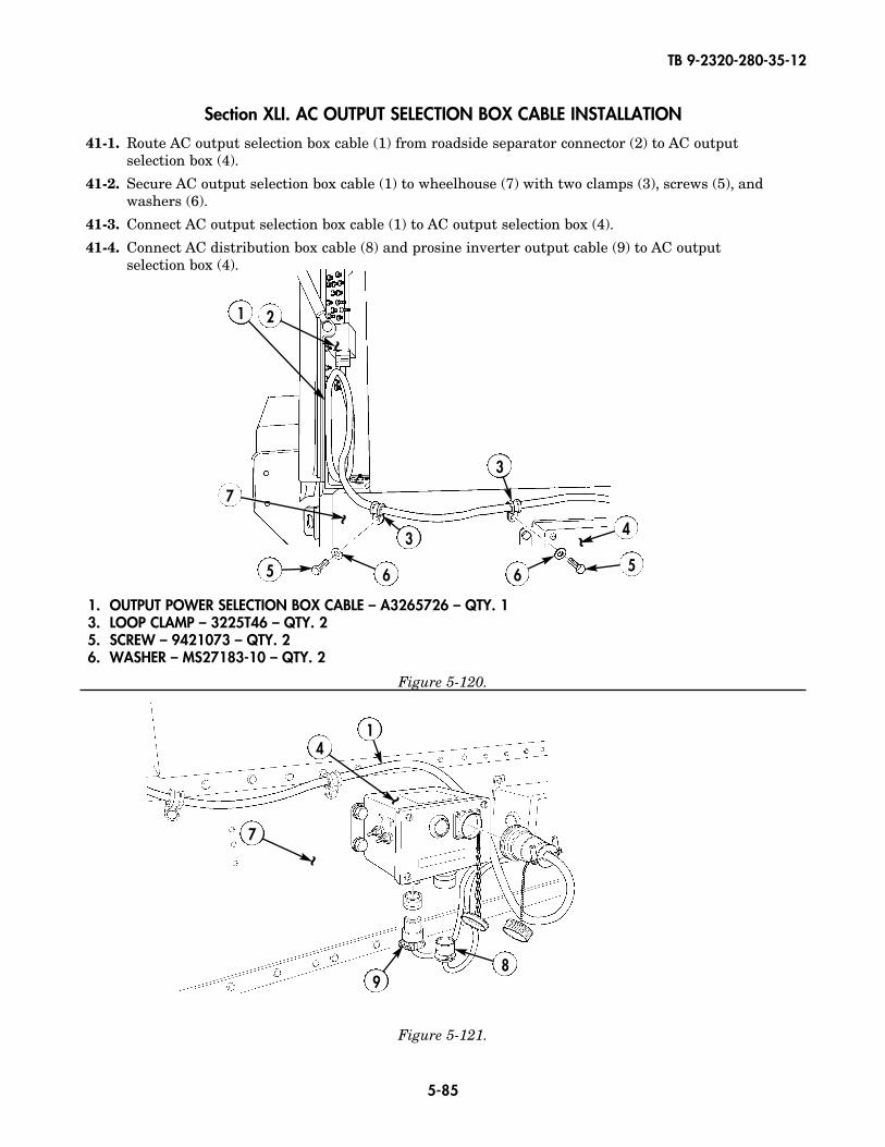
TB 9-2320-280-35-12
5-85
1. OUTPUT POWER SELECTION BOX CABLE – A3265726 – QTY. 13. LOOP CLAMP – 3225T46 – QTY. 25. SCREW – 9421073 – QTY. 26. WASHER – MS27183-10 – QTY. 2
Figure 5-121.
Figure 5-120.
Section XLI. AC OUTPUT SELECTION BOX CABLE INSTALLATION
41-1. Route AC output selection box cable (1) from roadside separator connector (2) to AC output selection box (4).
41-2. Secure AC output selection box cable (1) to wheelhouse (7) with two clamps (3), screws (5), andwashers (6).
41-3. Connect AC output selection box cable (1) to AC output selection box (4).
41-4. Connect AC distribution box cable (8) and prosine inverter output cable (9) to AC output selection box (4).
1 2
3
3 4
55 66
7
~~ ~
14
7
89
~
~
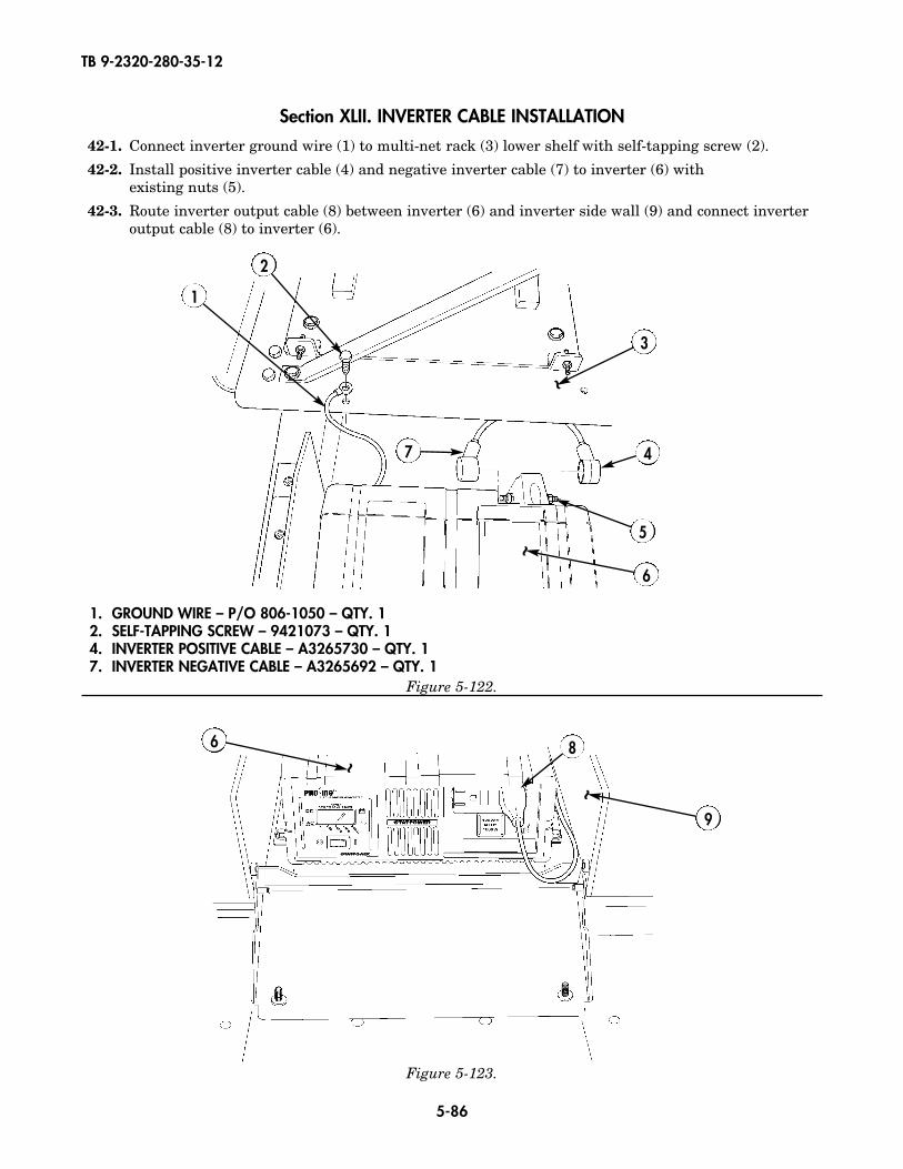
TB 9-2320-280-35-12
5-86
Section XLII. INVERTER CABLE INSTALLATION
42-1. Connect inverter ground wire (1) to multi-net rack (3) lower shelf with self-tapping screw (2).
42-2. Install positive inverter cable (4) and negative inverter cable (7) to inverter (6) with existing nuts (5).
42-3. Route inverter output cable (8) between inverter (6) and inverter side wall (9) and connect inverteroutput cable (8) to inverter (6).
1
2
4
3
5
6
8
7
~
~
9
~
Figure 5-122.
1. GROUND WIRE – P/O 806-1050 – QTY. 12. SELF-TAPPING SCREW – 9421073 – QTY. 14. INVERTER POSITIVE CABLE – A3265730 – QTY. 17. INVERTER NEGATIVE CABLE – A3265692 – QTY. 1
6
~
Figure 5-123.
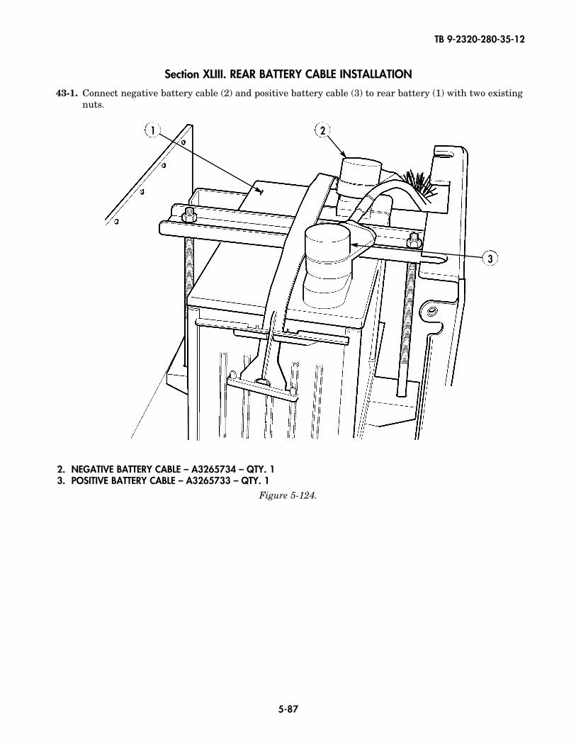
TB 9-2320-280-35-12
5-87
Figure 5-124.
Section XLIII. REAR BATTERY CABLE INSTALLATION
43-1. Connect negative battery cable (2) and positive battery cable (3) to rear battery (1) with two existingnuts.
2. NEGATIVE BATTERY CABLE – A3265734 – QTY. 13. POSITIVE BATTERY CABLE – A3265733 – QTY. 1
2
3
1
~
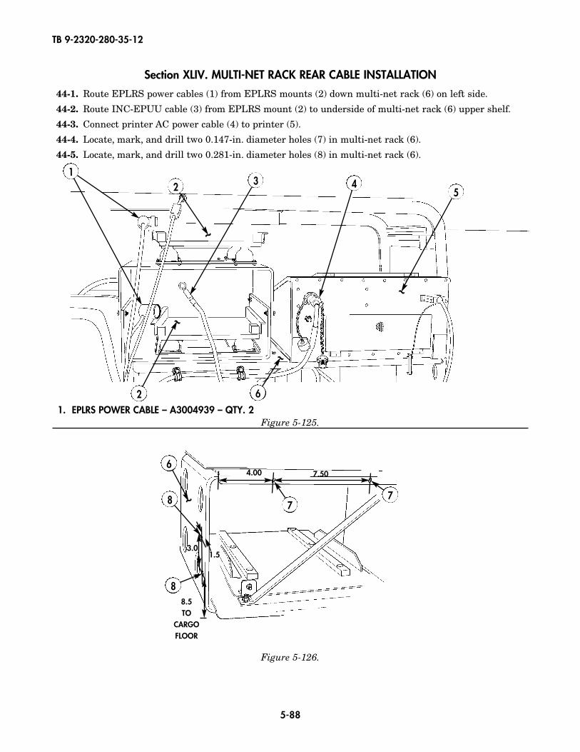
TB 9-2320-280-35-12
5-88
Section XLIV. MULTI-NET RACK REAR CABLE INSTALLATION
44-1. Route EPLRS power cables (1) from EPLRS mounts (2) down multi-net rack (6) on left side.
44-2. Route INC-EPUU cable (3) from EPLRS mount (2) to underside of multi-net rack (6) upper shelf.
44-3. Connect printer AC power cable (4) to printer (5).
44-4. Locate, mark, and drill two 0.147-in. diameter holes (7) in multi-net rack (6).
44-5. Locate, mark, and drill two 0.281-in. diameter holes (8) in multi-net rack (6).
Figure 5-126.
1. EPLRS POWER CABLE – A3004939 – QTY. 2
2 3 4
~
2
~
5
~
1
6
~
778
8
4.00
8.5TO
CARGOFLOOR
3.01.5
7.50
Figure 5-125.
6
~
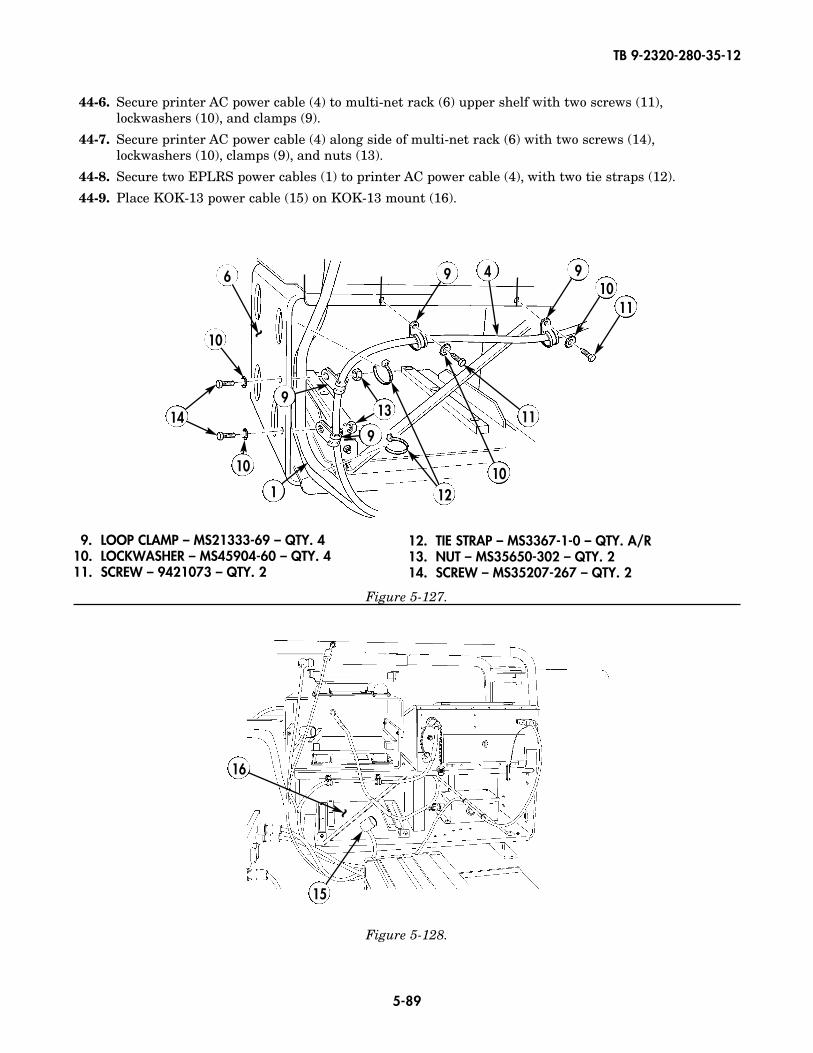
TB 9-2320-280-35-12
5-89
Figure 5-128.
9. LOOP CLAMP – MS21333-69 – QTY. 410. LOCKWASHER – MS45904-60 – QTY. 411. SCREW – 9421073 – QTY. 2
12. TIE STRAP – MS3367-1-0 – QTY. A/R13. NUT – MS35650-302 – QTY. 214. SCREW – MS35207-267 – QTY. 2
44-6. Secure printer AC power cable (4) to multi-net rack (6) upper shelf with two screws (11),lockwashers (10), and clamps (9).
44-7. Secure printer AC power cable (4) along side of multi-net rack (6) with two screws (14),lockwashers (10), clamps (9), and nuts (13).
44-8. Secure two EPLRS power cables (1) to printer AC power cable (4), with two tie straps (12).
44-9. Place KOK-13 power cable (15) on KOK-13 mount (16).
109
9
9
9 4
11
11
10
6
10
10
~
14
121
13
Figure 5-127.
15
16
~
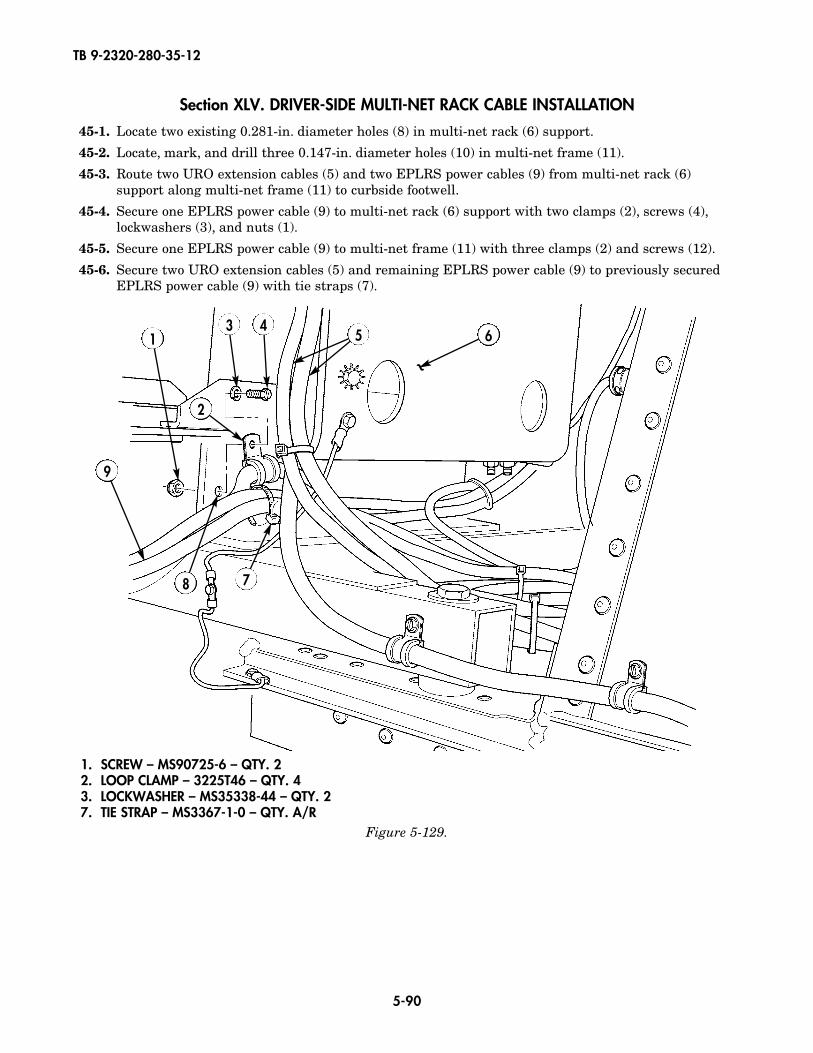
TB 9-2320-280-35-12
5-90
Section XLV. DRIVER-SIDE MULTI-NET RACK CABLE INSTALLATION
45-1. Locate two existing 0.281-in. diameter holes (8) in multi-net rack (6) support.
45-2. Locate, mark, and drill three 0.147-in. diameter holes (10) in multi-net frame (11).
45-3. Route two URO extension cables (5) and two EPLRS power cables (9) from multi-net rack (6)support along multi-net frame (11) to curbside footwell.
45-4. Secure one EPLRS power cable (9) to multi-net rack (6) support with two clamps (2), screws (4),lockwashers (3), and nuts (1).
45-5. Secure one EPLRS power cable (9) to multi-net frame (11) with three clamps (2) and screws (12).
45-6. Secure two URO extension cables (5) and remaining EPLRS power cable (9) to previously securedEPLRS power cable (9) with tie straps (7).
1
2
3 45 6
78
9
~
Figure 5-129.
1. SCREW – MS90725-6 – QTY. 22. LOOP CLAMP – 3225T46 – QTY. 43. LOCKWASHER – MS35338-44 – QTY. 27. TIE STRAP – MS3367-1-0 – QTY. A/R

TB 9-2320-280-35-12
5-91
Figure 5-130.
2. LOOP CLAMP – 3225T46 – QTY. 37. TIE STRAP – MS3367-1-0 – QTY. A/R
12. SCREW – 9421073 – QTY. 3
2 12
11
10
5
99
7
~12.0
12.0TO NEXT
HOLE
8.75TO EDGE
OFFRAME
0.75
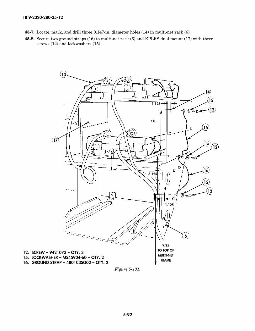
TB 9-2320-280-35-12
5-92
45-7. Locate, mark, and drill three 0.147-in. diameter holes (14) in multi-net rack (6).
45-8. Secure two ground straps (16) to multi-net rack (6) and EPLRS dual mount (17) with three screws (12) and lockwashers (15).
16
12
12
12
6
16
15
15
15
17
14
13
~
1.125
7.0
6.125
1.125
9.25TO TOP OFMULTI-NET
FRAME
12. SCREW – 9421073 – QTY. 315. LOCKWASHER – MS45904-60 – QTY. 216. GROUND STRAP – 4801C3SG02 – QTY. 2
Figure 5-131.
~
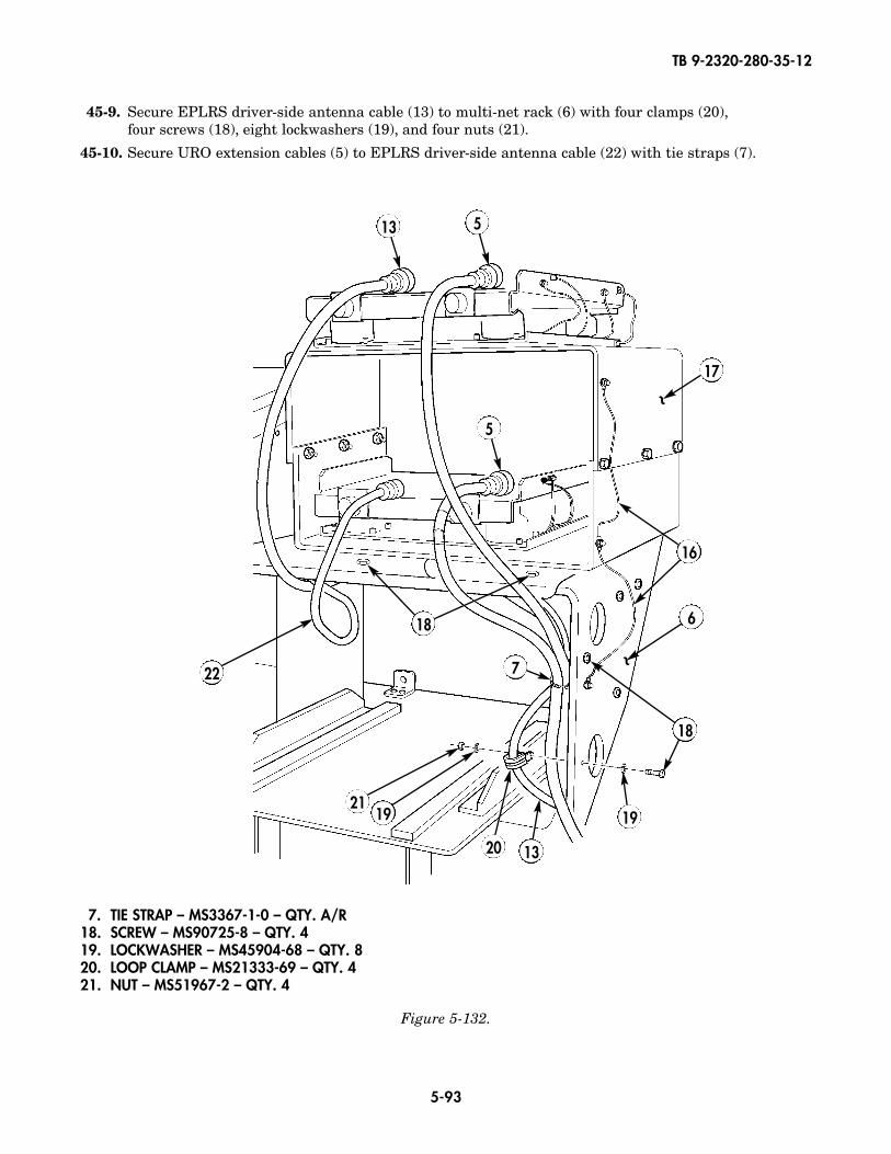
TB 9-2320-280-35-12
5-93
6
13
17
5
5
191921
22
20 13
7
~
~
7. TIE STRAP – MS3367-1-0 – QTY. A/R18. SCREW – MS90725-8 – QTY. 419. LOCKWASHER – MS45904-68 – QTY. 820. LOOP CLAMP – MS21333-69 – QTY. 421. NUT – MS51967-2 – QTY. 4
Figure 5-132.
16
18
45-9. Secure EPLRS driver-side antenna cable (13) to multi-net rack (6) with four clamps (20),four screws (18), eight lockwashers (19), and four nuts (21).
45-10. Secure URO extension cables (5) to EPLRS driver-side antenna cable (22) with tie straps (7).
18
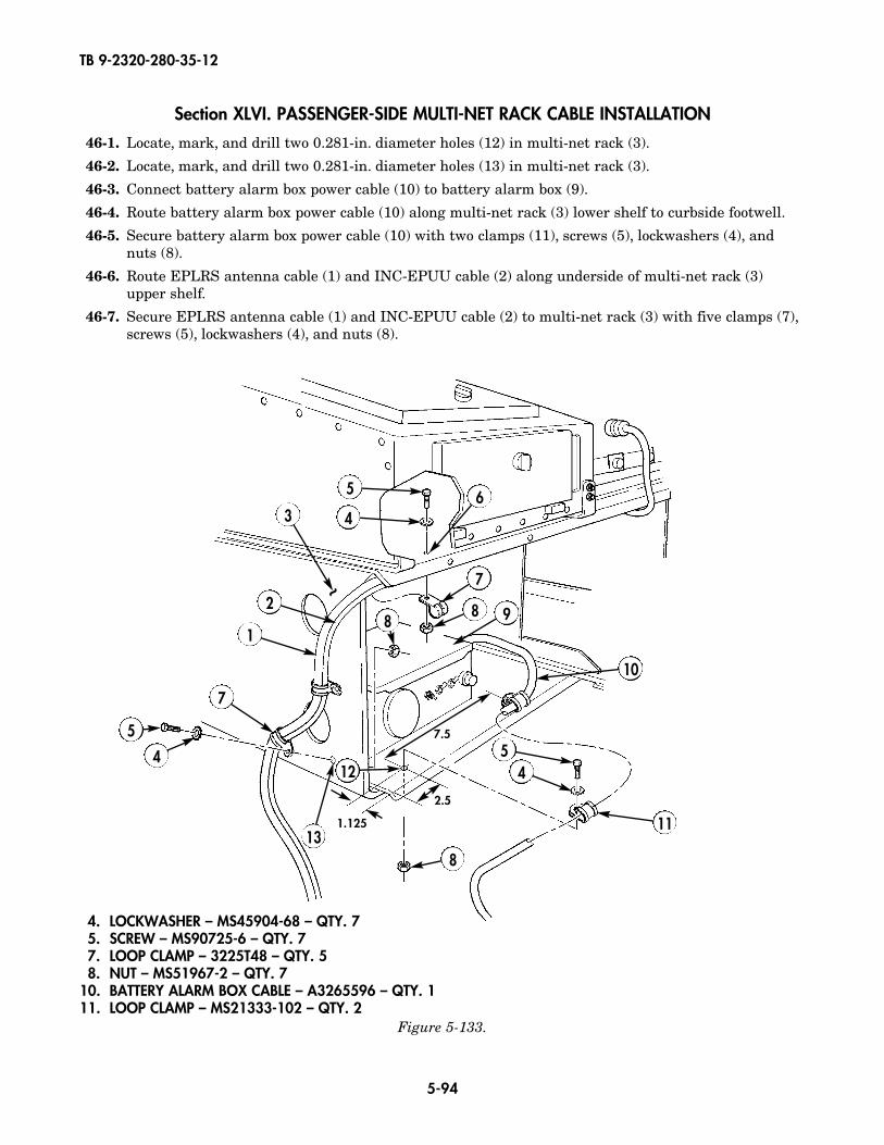
TB 9-2320-280-35-12
5-94
Section XLVI. PASSENGER-SIDE MULTI-NET RACK CABLE INSTALLATION
46-1. Locate, mark, and drill two 0.281-in. diameter holes (12) in multi-net rack (3).
46-2. Locate, mark, and drill two 0.281-in. diameter holes (13) in multi-net rack (3).
46-3. Connect battery alarm box power cable (10) to battery alarm box (9).
46-4. Route battery alarm box power cable (10) along multi-net rack (3) lower shelf to curbside footwell.
46-5. Secure battery alarm box power cable (10) with two clamps (11), screws (5), lockwashers (4), andnuts (8).
46-6. Route EPLRS antenna cable (1) and INC-EPUU cable (2) along underside of multi-net rack (3)upper shelf.
46-7. Secure EPLRS antenna cable (1) and INC-EPUU cable (2) to multi-net rack (3) with five clamps (7),screws (5), lockwashers (4), and nuts (8).
1
7
2
3 4
5 6
7
8 9
10
11
12
8
8
454
5
1.125
2.5
7.5
13
4. LOCKWASHER – MS45904-68 – QTY. 75. SCREW – MS90725-6 – QTY. 77. LOOP CLAMP – 3225T48 – QTY. 58. NUT – MS51967-2 – QTY. 7
10. BATTERY ALARM BOX CABLE – A3265596 – QTY. 111. LOOP CLAMP – MS21333-102 – QTY. 2
Figure 5-133.
~
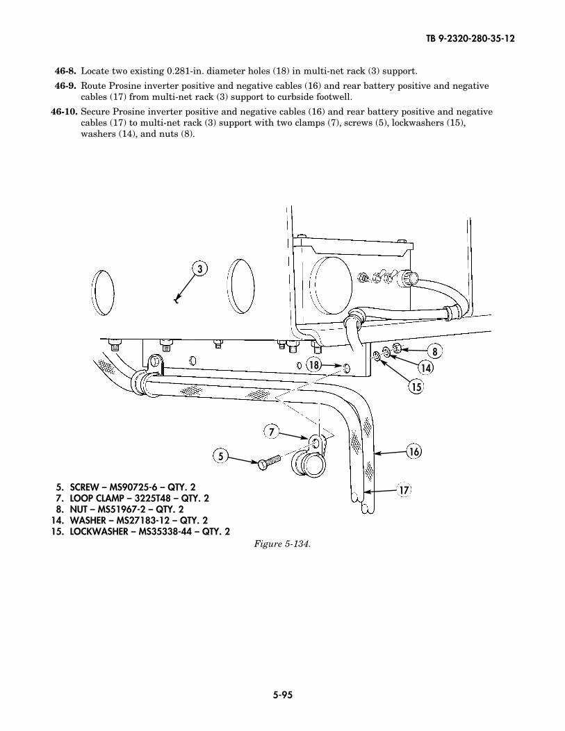
TB 9-2320-280-35-12
5-95
3
188
14
15
16
17
5
7
5. SCREW – MS90725-6 – QTY. 27. LOOP CLAMP – 3225T48 – QTY. 28. NUT – MS51967-2 – QTY. 2
14. WASHER – MS27183-12 – QTY. 215. LOCKWASHER – MS35338-44 – QTY. 2
Figure 5-134.
46-8. Locate two existing 0.281-in. diameter holes (18) in multi-net rack (3) support.
46-9. Route Prosine inverter positive and negative cables (16) and rear battery positive and negativecables (17) from multi-net rack (3) support to curbside footwell.
46-10. Secure Prosine inverter positive and negative cables (16) and rear battery positive and negativecables (17) to multi-net rack (3) support with two clamps (7), screws (5), lockwashers (15),washers (14), and nuts (8).
~
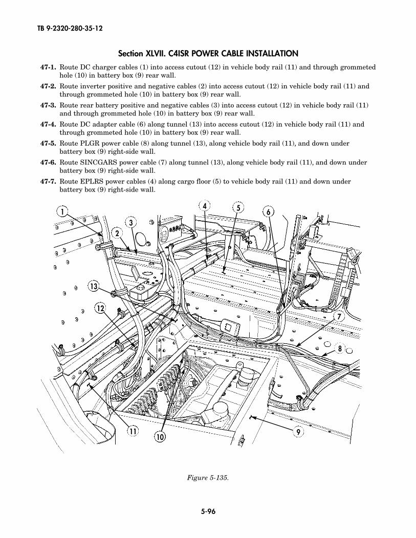
TB 9-2320-280-35-12
5-96
Section XLVII. C4ISR POWER CABLE INSTALLATION
47-1. Route DC charger cables (1) into access cutout (12) in vehicle body rail (11) and through grommetedhole (10) in battery box (9) rear wall.
47-2. Route inverter positive and negative cables (2) into access cutout (12) in vehicle body rail (11) andthrough grommeted hole (10) in battery box (9) rear wall.
47-3. Route rear battery positive and negative cables (3) into access cutout (12) in vehicle body rail (11)and through grommeted hole (10) in battery box (9) rear wall.
47-4. Route DC adapter cable (6) along tunnel (13) into access cutout (12) in vehicle body rail (11) andthrough grommeted hole (10) in battery box (9) rear wall.
47-5. Route PLGR power cable (8) along tunnel (13), along vehicle body rail (11), and down under battery box (9) right-side wall.
47-6. Route SINCGARS power cable (7) along tunnel (13), along vehicle body rail (11), and down under battery box (9) right-side wall.
47-7. Route EPLRS power cables (4) along cargo floor (5) to vehicle body rail (11) and down under battery box (9) right-side wall.
1
23
4 5
7
9
12
13
11
8
6
~
~
~
~
~
10
Figure 5-135.

TB 9-2320-280-35-12
5-97
47-8. Route battery alarm box cable (14) along tunnel (13) and down into grommeted hole (18) in battery box (9) forward wall.
47-9. Route master kill switch box cable (17) along tunnel (13) and down into grommeted hole (18) in battery box (9) forward wall.
47-10. Route INC-EPUU cable (15) through grommeted hole (19) in cab enclosure panel (20) and along tunnel (13) to multi-net rack.
47-11. Route shunt cable (21) through grommeted hole (19) in cab enclosure panel (20) to negative terminalof vehicle battery.
47-12. Route battery alarm box control cable (16) from battery box (9) through cab enclosure panel (20) tofront of vehicle.
Figure 5-136.
Figure 5-137.
14 15
15
16
17
13
15
19
20
21
16
18
13
9
~
~~
~
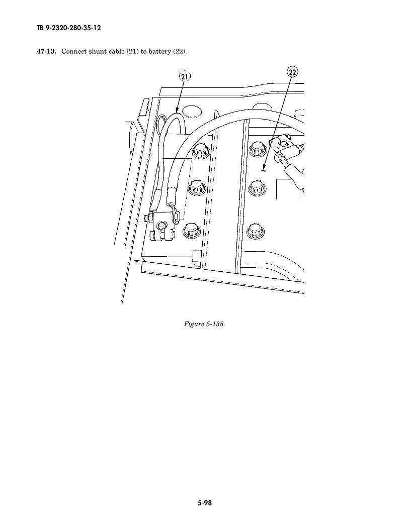
TB 9-2320-280-35-12
5-98
Figure 5-138.
47-13. Connect shunt cable (21) to battery (22).
21 22
~~

TB 9-2320-280-35-12
5-99
Figure 5-139.
47-14. Route battery alarm box control cable (16) from battery box and around intregrated rack to left-sidefirewall (26).
47-15. Route battery alarm box control cable (16) up firewall (26).47-16. Secure battery alarm box control cable (16) to firewall (26) with two clamps (24) and self-tapping
screws (25).47-17. Route battery alarm box control cable (16) under dash panel (23).
23
25
26
16
24
~
~
24. LOOP CLAMP – MS21333-71 – QTY. 225. SELF-TAPPING SCREW – 9421073 – QTY. 2
24
25
5.00
4.00
2.25
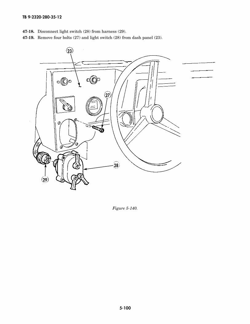
TB 9-2320-280-35-12
5-100
47-18. Disconnect light switch (28) from harness (29).47-19. Remove four bolts (27) and light switch (28) from dash panel (23).
Figure 5-140.
28
29
23
27
~
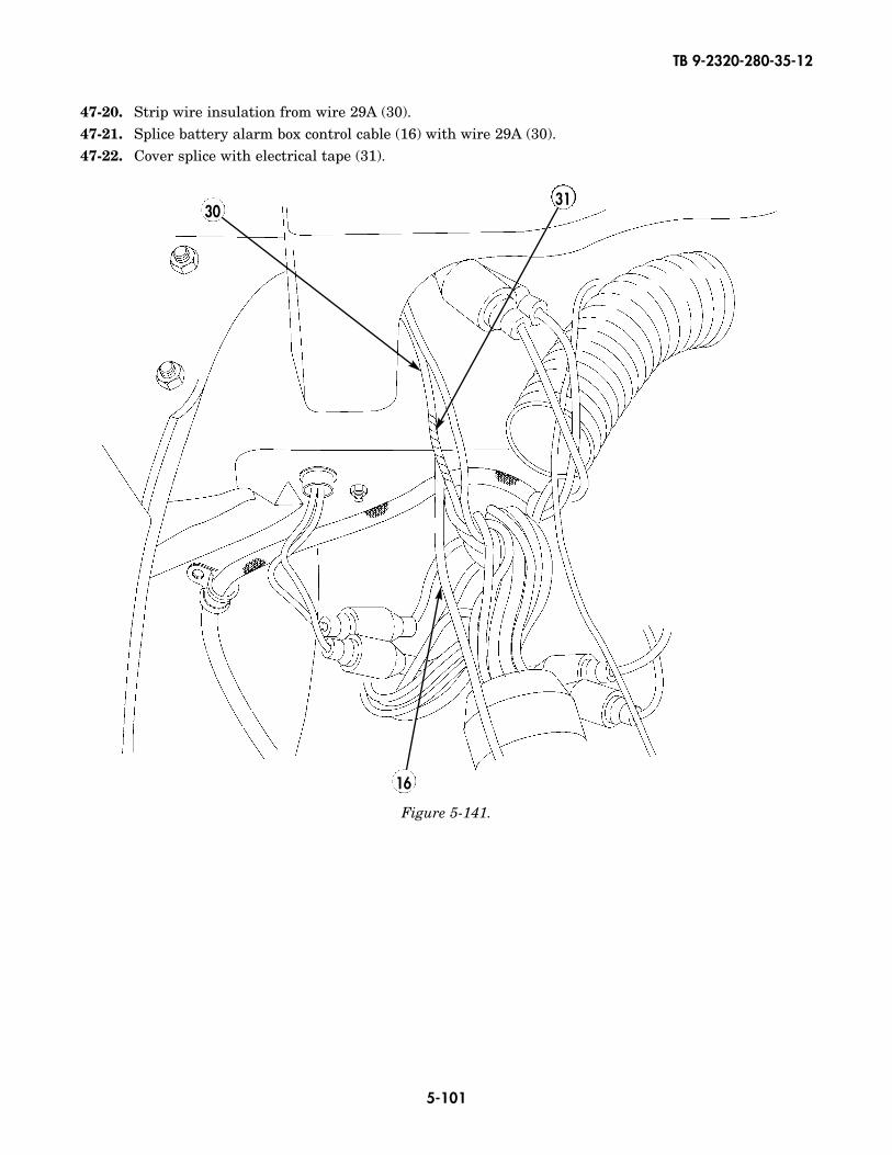
TB 9-2320-280-35-12
5-101
Figure 5-141.
47-20. Strip wire insulation from wire 29A (30).47-21. Splice battery alarm box control cable (16) with wire 29A (30).47-22. Cover splice with electrical tape (31).
16
3130
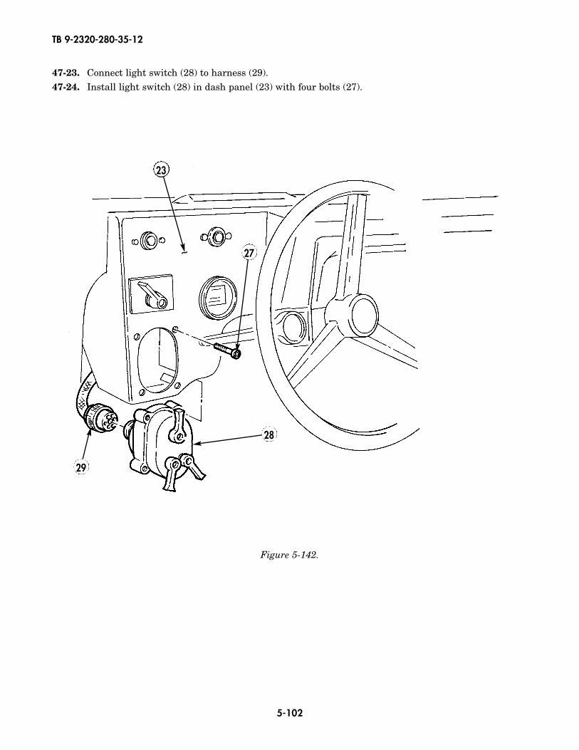
TB 9-2320-280-35-12
5-102
Figure 5-142.
47-23. Connect light switch (28) to harness (29).47-24. Install light switch (28) in dash panel (23) with four bolts (27).
28
29
27
23
~
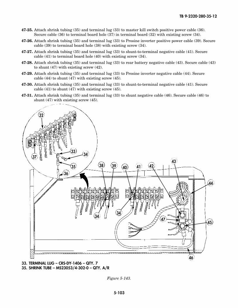
TB 9-2320-280-35-12
5-103
47-25. Attach shrink tubing (35) and terminal lug (33) to master kill switch positive power cable (36).Secure cable (36) to terminal board hole (37) in terminal board (32) with existing screw (34).
47-26. Attach shrink tubing (35) and terminal lug (33) to Prosine inverter positive power cable (39). Securecable (39) to terminal board hole (38) with existing screw (34).
47-27. Attach shrink tubing (35) and terminal lug (33) to shunt-to-terminal negative cable (41). Securecable (41) to terminal board hole (40) with existing screw (34).
47-28. Attach shrink tubing (35) and terminal lug (33) to rear battery negative cable (43). Secure cable (43)to shunt (47) with existing screw (42).
47-29. Attach shrink tubing (35) and terminal lug (33) to Prosine inverter negative cable (44). Secure cable (44) to shunt (47) with existing screw (45).
47-30. Attach shrink tubing (35) and terminal lug (33) to shunt-to-terminal negative cable (41). Securecable (41) to shunt (47) with existing screw (45).
47-31. Attach shrink tubing (35) and terminal lug (33) to shunt negative cable (46). Secure cable (46) toshunt (47) with existing screw (45).
38 39 40 41 4243
44
45
46
47
32
3334
3536
37
Figure 5-143.
33. TERMINAL LUG – CRS-DY-1406 – QTY. 735. SHRINK TUBE – MS23053/4-302-0 – QTY. A/R
3434
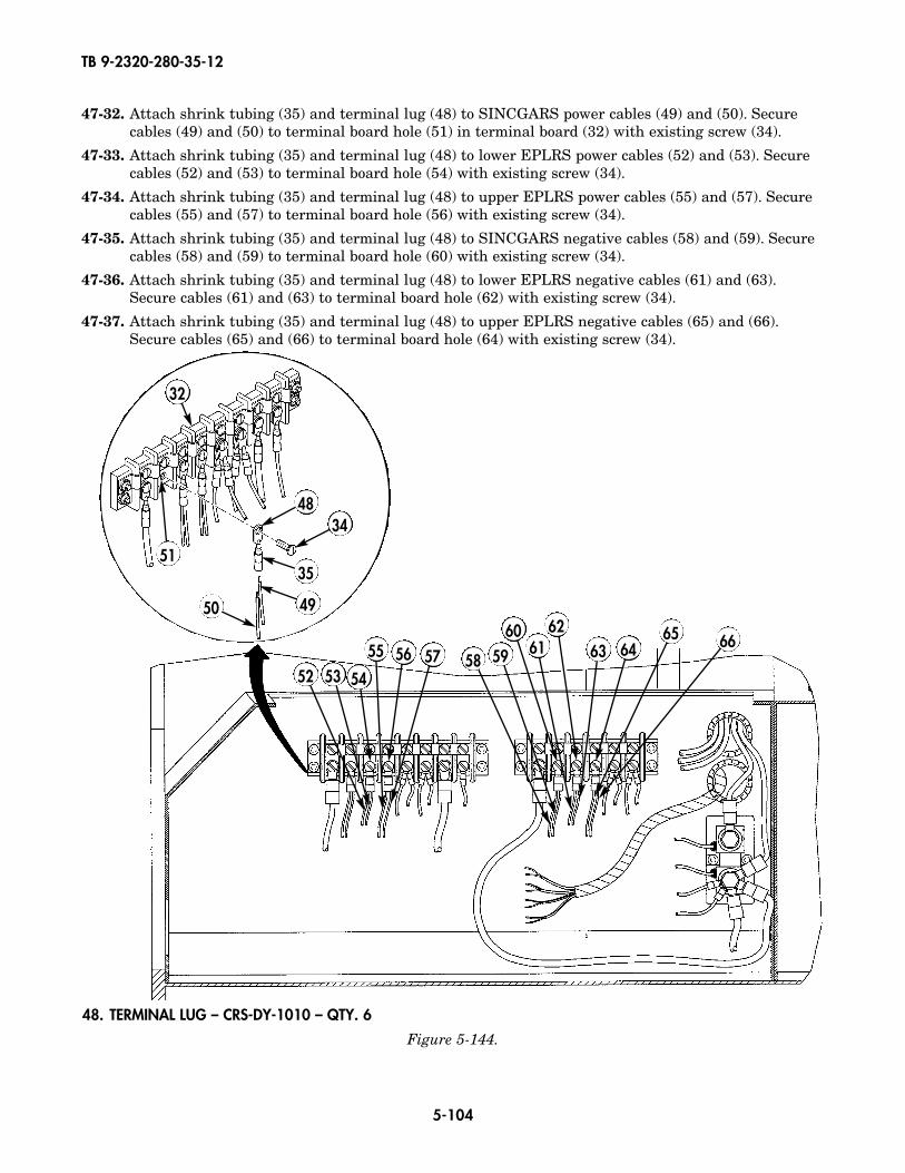
TB 9-2320-280-35-12
5-104
47-32. Attach shrink tubing (35) and terminal lug (48) to SINCGARS power cables (49) and (50). Securecables (49) and (50) to terminal board hole (51) in terminal board (32) with existing screw (34).
47-33. Attach shrink tubing (35) and terminal lug (48) to lower EPLRS power cables (52) and (53). Securecables (52) and (53) to terminal board hole (54) with existing screw (34).
47-34. Attach shrink tubing (35) and terminal lug (48) to upper EPLRS power cables (55) and (57). Securecables (55) and (57) to terminal board hole (56) with existing screw (34).
47-35. Attach shrink tubing (35) and terminal lug (48) to SINCGARS negative cables (58) and (59). Securecables (58) and (59) to terminal board hole (60) with existing screw (34).
47-36. Attach shrink tubing (35) and terminal lug (48) to lower EPLRS negative cables (61) and (63).Secure cables (61) and (63) to terminal board hole (62) with existing screw (34).
47-37. Attach shrink tubing (35) and terminal lug (48) to upper EPLRS negative cables (65) and (66).Secure cables (65) and (66) to terminal board hole (64) with existing screw (34).
32
4834
35
4950
51
58 5960 62
63 6465 6661
52 53 54
55 56 57
Figure 5-144.
48. TERMINAL LUG – CRS-DY-1010 – QTY. 6
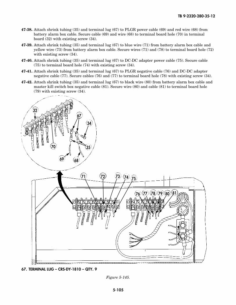
TB 9-2320-280-35-12
5-105
Figure 5-145.
67. TERMINAL LUG – CRS-DY-1810 – QTY. 9
47-38. Attach shrink tubing (35) and terminal lug (67) to PLGR power cable (69) and red wire (68) frombattery alarm box cable. Secure cable (69) and wire (68) to terminal board hole (70) in terminalboard (32) with existing screw (34).
47-39. Attach shrink tubing (35) and terminal lug (67) to blue wire (71) from battery alarm box cable andyellow wire (73) from battery alarm box cable. Secure wires (71) and (78) to terminal board hole (72)with existing screw (34).
47-40. Attach shrink tubing (35) and terminal lug (67) to DC-DC adapter power cable (75). Secure cable(75) to terminal board hole (74) with existing screw (34).
47-41. Attach shrink tubing (35) and terminal lug (67) to PLGR negative cable (76) and DC-DC adapternegative cable (77). Secure cables (76) and (77) to terminal board hole (78) with existing screw (34).
47-42. Attach shrink tubing (35) and terminal lug (67) to black wire (80) from battery alarm box cable andmaster kill switch box negative cable (81). Secure wire (80) and cable (81) to terminal board hole(79) with existing screw (34).
71 72 73 74 75
76 77 78 79 80 81
32
70
67
34
35
6869
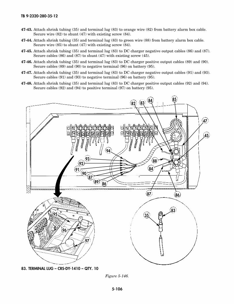
TB 9-2320-280-35-12
5-106
47-43. Attach shrink tubing (35) and terminal lug (83) to orange wire (82) from battery alarm box cable.Secure wire (82) to shunt (47) with existing screw (84).
47-44. Attach shrink tubing (35) and terminal lug (83) to green wire (88) from battery alarm box cable.Secure wire (85) to shunt (47) with existing screw (84).
47-45. Attach shrink tubing (35) and terminal lug (83) to DC charger negative output cables (86) and (87).Secure cables (86) and (87) to shunt (47) with existing screw (45).
47-46. Attach shrink tubing (35) and terminal lug (83) to DC charger positive output cables (89) and (90).Secure cables (89) and (90) to negative terminal (96) on battery (95).
47-47. Attach shrink tubing (35) and terminal lug (83) to DC charger negative output cables (91) and (93).Secure cables (91) and (93) to negative terminal (96) on battery (95).
47-48. Attach shrink tubing (35) and terminal lug (83) to DC charger positive output cables (92) and (94).Secure cables (92) and (94) to positive terminal (97) on battery (95).
82 83 84 85
47
45
86
868987
9091
9293
94
87
84
88
95
96
97
3583
Figure 5-146.
83. TERMINAL LUG – CRS-DY-1410 – QTY. 10
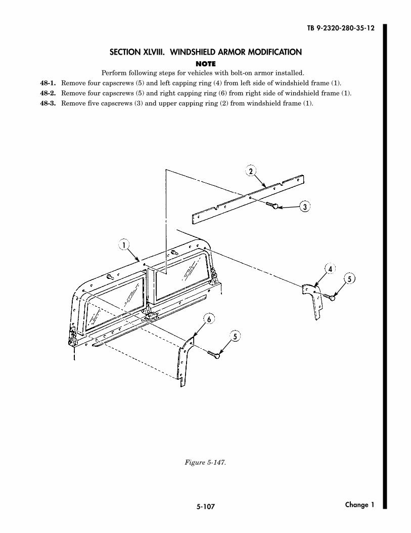
5-107
TB 9-2320-280-35-12
Change 1
Figure 5-147.
1
2
3
45
5
6
SECTION XLVIII. WINDSHIELD ARMOR MODIFICATIONNOTE
Perform following steps for vehicles with bolt-on armor installed.48-1. Remove four capscrews (5) and left capping ring (4) from left side of windshield frame (1).48-2. Remove four capscrews (5) and right capping ring (6) from right side of windshield frame (1).48-3. Remove five capscrews (3) and upper capping ring (2) from windshield frame (1).
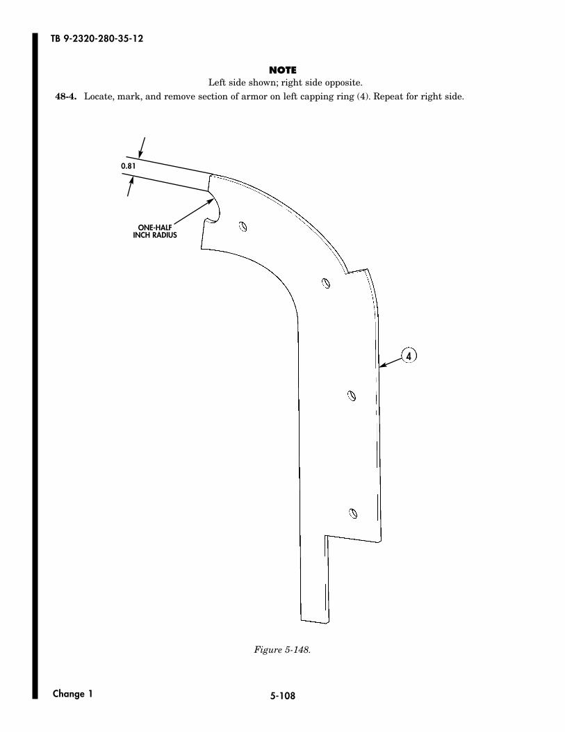
5-108
TB 9-2320-280-35-12
Change 1
NOTELeft side shown; right side opposite.
48-4. Locate, mark, and remove section of armor on left capping ring (4). Repeat for right side.
0.81
ONE-HALFINCH RADIUS
4
Figure 5-148.

5-109
TB 9-2320-280-35-12
Change 1
NOTERight side shown; left side opposite.
48-5. Locate, mark, and remove sections of armor on upper capping ring (2).48-6. Spot paint all exposed metal surfaces. (Refer to TM 43-0139.)
Figure 5-149.
0.81 0.87
0.87
0.50
3.12
ONE-HALFINCH RADIUS
2
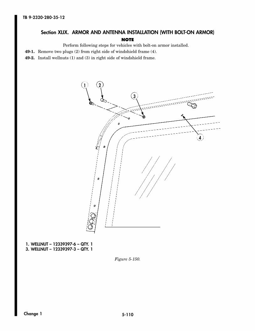
5-110
TB 9-2320-280-35-12
Change 1
Section XLIX. ARMOR AND ANTENNA INSTALLATION (WITH BOLT-ON ARMOR)NOTE
Perform following steps for vehicles with bolt-on armor installed.49-1. Remove two plugs (2) from right side of windshield frame (4).49-2. Install wellnuts (1) and (3) in right side of windshield frame.
1 2
3
4
~
1. WELLNUT – 12339397-6 – QTY. 13. WELLNUT – 12339397-3 – QTY. 1
Figure 5-150.
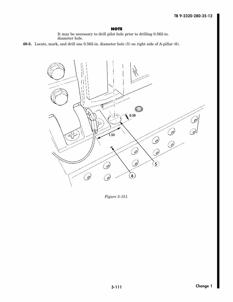
5-111
TB 9-2320-280-35-12
Change 1
NOTEIt may be necessary to drill pilot hole prior to drilling 0.562-in.diameter hole.
49-3. Locate, mark, and drill one 0.562-in. diameter hole (5) on right side of A-pillar (6).
Figure 5-151.
0.50
1.53
~
6
5
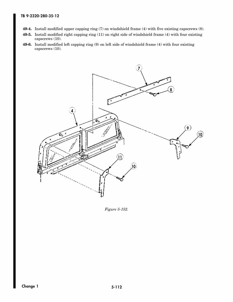
5-112
TB 9-2320-280-35-12
Change 1
49-4. Install modified upper capping ring (7) on windshield frame (4) with five existing capscrews (8).49-5. Install modified right capping ring (11) on right side of windshield frame (4) with four existing
capscrews (10).49-6. Install modified left capping ring (9) on left side of windshield frame (4) with four existing
capscrews (10).
4
8
9
10
11
10
7
Figure 5-152.
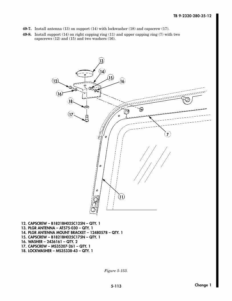
5-113
TB 9-2320-280-35-12
Change 1
49-7. Install antenna (13) on support (14) with lockwasher (18) and capscrew (17).49-8. Install support (14) on right capping ring (11) and upper capping ring (7) with two
capscrews (12) and (15) and two washers (16).
12
16
13
1514
16
7
11
18
17
Figure 5-153.
12. CAPSCREW – B1821BH025C125N – QTY. 113. PLGR ANTENNA – AT575-030 – QTY. 114. PLGR ANTENNA MOUNT BRACKET – 12480578 – QTY. 115. CAPSCREW – B1821BH025C175N – QTY. 116. WASHER – 2436161 – QTY. 217. CAPSCREW – MS35207-261 – QTY. 118. LOCKWASHER – MS35338-43 – QTY. 1
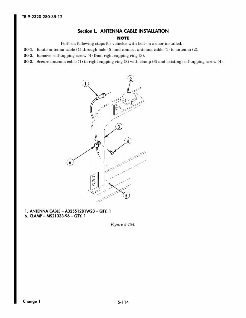
5-114
TB 9-2320-280-35-12
Change 1
Section L. ANTENNA CABLE INSTALLATIONNOTE
Perform following steps for vehicles with bolt-on armor installed.50-1. Route antenna cable (1) through hole (5) and connect antenna cable (1) to antenna (2).50-2. Remove self-tapping screw (4) from right capping ring (3).50-3. Secure antenna cable (1) to right capping ring (3) with clamp (6) and existing self-tapping screw (4).
3
4
2
6
5
1
Figure 5-154.
1. ANTENNA CABLE – A32551281W23 – QTY. 16. CLAMP – MS21333-96 – QTY. 1
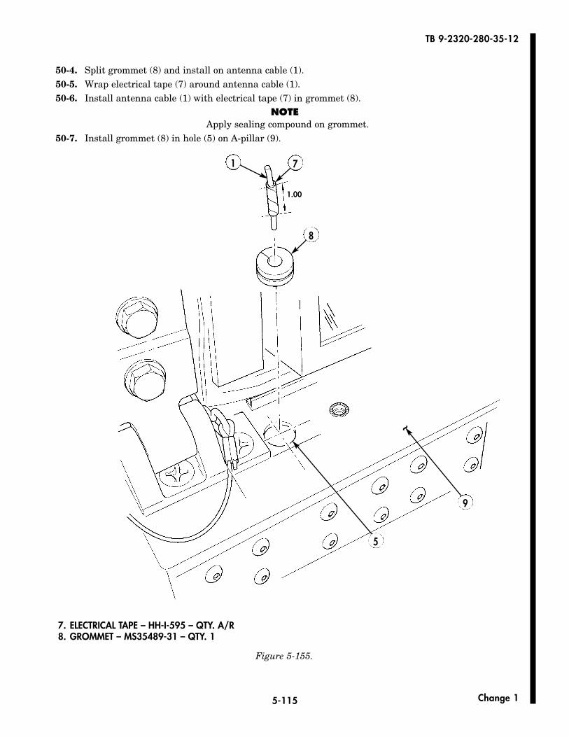
5-115
TB 9-2320-280-35-12
Change 1
50-4. Split grommet (8) and install on antenna cable (1).50-5. Wrap electrical tape (7) around antenna cable (1).50-6. Install antenna cable (1) with electrical tape (7) in grommet (8).
NOTEApply sealing compound on grommet.
50-7. Install grommet (8) in hole (5) on A-pillar (9).
5
9
1 7
8
1.00
~
Figure 5-155.
7. ELECTRICAL TAPE – HH-I-595 – QTY. A/R8. GROMMET – MS35489-31 – QTY. 1
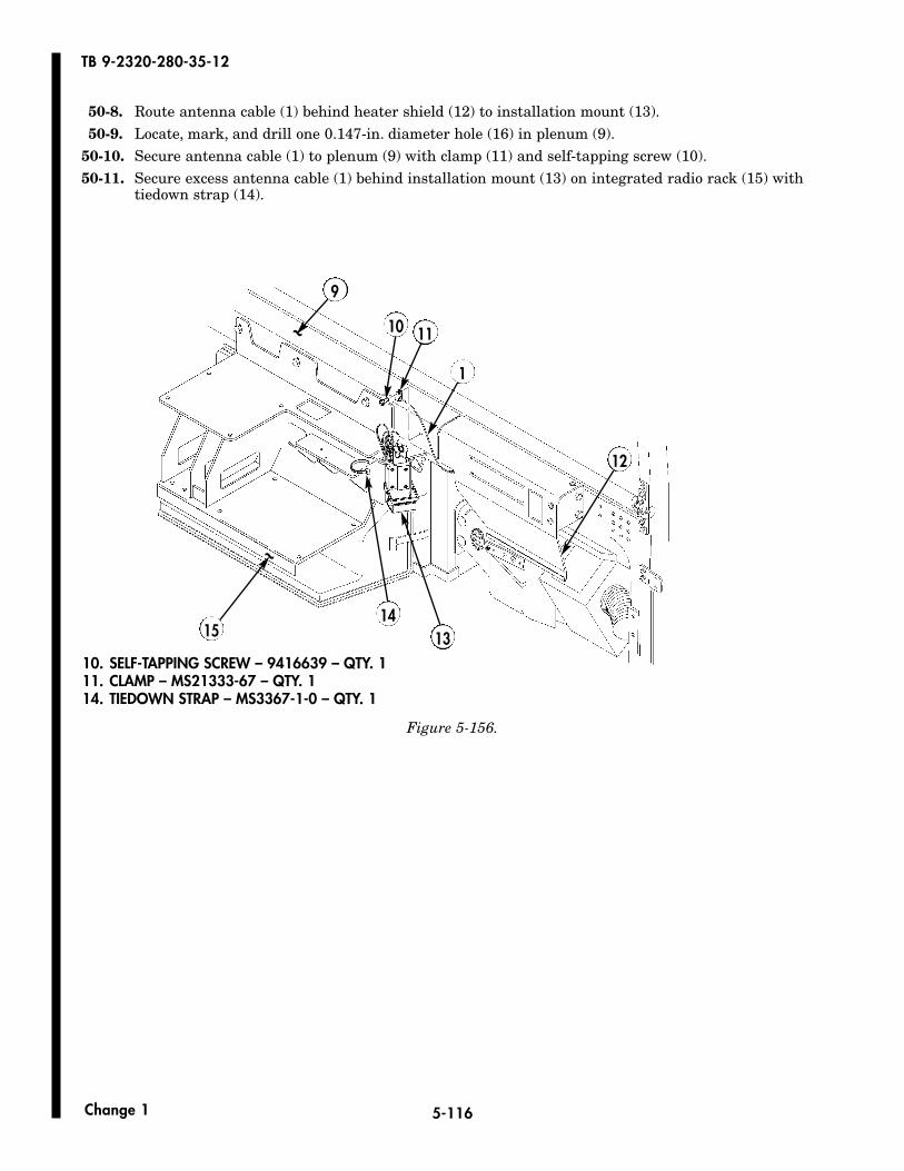
5-116
TB 9-2320-280-35-12
Change 1
50-8. Route antenna cable (1) behind heater shield (12) to installation mount (13).50-9. Locate, mark, and drill one 0.147-in. diameter hole (16) in plenum (9).
50-10. Secure antenna cable (1) to plenum (9) with clamp (11) and self-tapping screw (10).50-11. Secure excess antenna cable (1) behind installation mount (13) on integrated radio rack (15) with
tiedown strap (14).
1314
15
9
10 11
1
12
~
~
10. SELF-TAPPING SCREW – 9416639 – QTY. 111. CLAMP – MS21333-67 – QTY. 114. TIEDOWN STRAP – MS3367-1-0 – QTY. 1
Figure 5-156.

5-117/(5-118 blank)
TB 9-2320-280-35-12
Change 1
9
16~
18.50
0.75
M998A2 SERIES
Figure 5-157.

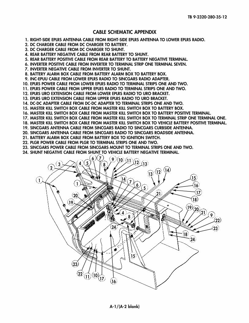
TB 9-2320-280-35-12
A-1/(A-2 blank)
CABLE SCHEMATIC APPENDIX1. RIGHT-SIDE EPLRS ANTENNA CABLE FROM RIGHT-SIDE EPLRS ANTENNA TO LOWER EPLRS RADIO.2. DC CHARGER CABLE FROM DC CHARGER TO BATTERY.3. DC CHARGER CABLE FROM DC CHARGER TO SHUNT.4. REAR BATTERY NEGATIVE CABLE FROM REAR BATTERY TO SHUNT.5. REAR BATTERY POSITIVE CABLE FROM REAR BATTERY TO BATTERY NEGATIVE TERMINAL.6. INVERTER POSITIVE CABLE FROM INVERTER TO TERMINAL STRIP ONE TERMINAL SEVEN.7. INVERTER NEGATIVE CABLE FROM INVERTER TO SHUNT.8. BATTERY ALARM BOX CABLE FROM BATTERY ALARM BOX TO BATTERY BOX.9. INC-EPUU CABLE FROM LOWER EPLRS RADIO TO SINCGARS RADIO ADAPTER.
10. EPLRS POWER CABLE FROM LOWER EPLRS RADIO TO TERMINAL STRIPS ONE AND TWO.11. EPLRS POWER CABLE FROM UPPER EPLRS RADIO TO TERMINAL STRIPS ONE AND TWO.12. EPLRS URO EXTENSION CABLE FROM LOWER EPLRS RADIO TO URO BRACKET.13. EPLRS URO EXTENSION CABLE FROM UPPER EPLRS RADIO TO URO BRACKET.14. DC-DC ADAPTER CABLE FROM DC-DC ADAPTER TO TERMINAL STRIPS ONE AND TWO.15. MASTER KILL SWITCH BOX CABLE FROM MASTER KILL SWITCH BOX TO BATTERY BOX.16. MASTER KILL SWITCH BOX CABLE FROM MASTER KILL SWITCH BOX TO BATTERY POSITIVE TERMINAL.17. MASTER KILL SWITCH BOX CABLE FROM MASTER KILL SWITCH BOX TO TERMINAL STRIP ONE TERMINAL ONE.18. MASTER KILL SWITCH BOX CABLE FROM MASTER KILL SWITCH BOX TO VEHICLE BATTERY POSITIVE TERMINAL.19. SINCGARS ANTENNA CABLE FROM SINCGARS RADIO TO SINCGARS CURBSIDE ANTENNA.20. SINCGARS ANTENNA CABLE FROM SINCGARS RADIO TO SINCGARS ROADSIDE ANTENNA.21. BATTERY ALARM BOX CABLE FROM BATTERY BOX TO IGNITION SWITCH.22. PLGR POWER CABLE FROM PLGR TO TERMINAL STRIPS ONE AND TWO.23. SINCGARS POWER CABLE FROM SINCGARS MOUNT TO TERMINAL STRIPS ONE AND TWO.24. SHUNT NEGATIVE CABLE FROM SHUNT TO VEHICLE BATTERY NEGATIVE TERMINAL.
11
23 4 5
6 78
9 10 11 12 13
1314
76
5
48
21
24
1920
16171011
22
23
15
12 14
15
16
1718
19 2021 9
22
2318
24


Distribution:
To be distributed in accordance with the Initial Distribution Number (IDN) 344840 requirements for TB 9-2320-280-35-12.
By Order of the Secretary of the Army:
SANDRA R. RILEYAdministrative Assistant to the
Secretary of the Army0533602
PETER J. SCHOOMAKERGeneral, United States Army
Chief of Staff
Official:

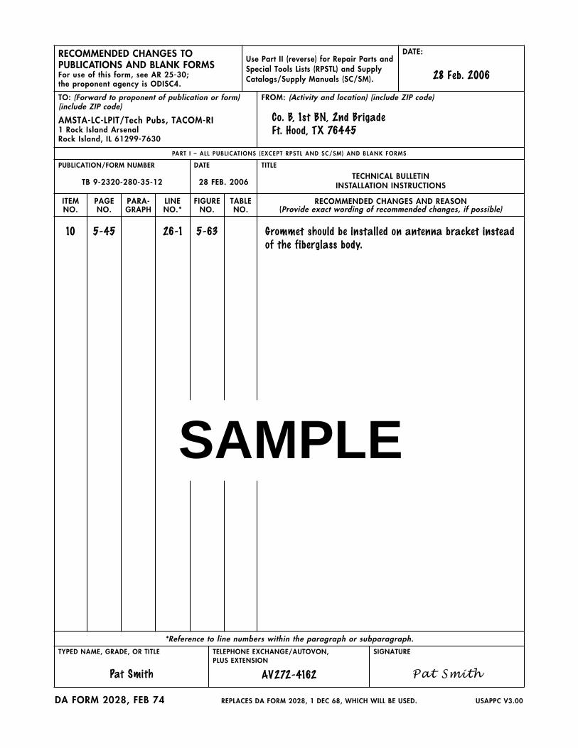
RECOMMENDED CHANGES TO PUBLICATIONS AND BLANK FORMSFor use of this form, see AR 25-30; the proponent agency is ODISC4.
Use Part II (reverse) for Repair Parts andSpecial Tools Lists (RPSTL) and SupplyCatalogs/Supply Manuals (SC/SM).
DATE:
28 Feb. 2006
TO: (Forward to proponent of publication or form) (include ZIP code)
AMSTA-LC-LPIT/Tech Pubs, TACOM-RI1 Rock Island ArsenalRock Island, IL 61299-7630
FROM: (Activity and location) (include ZIP code)
Co. B, 1st BN, 2nd BrigadeFt. Hood, TX 76445
PART I – ALL PUBL ICAT IONS (EXCEPT RPSTL AND SC/SM) AND BLANK FORMS
PUBLICATION/FORM NUMBER
TB 9-2320-280-35-12
DATE
28 FEB. 2006
TITLE
TECHNICAL BULLETININSTALLATION INSTRUCTIONS
ITEMNO.
PAGENO.
PARA-GRAPH
LINENO.*
FIGURENO.
TABLENO.
RECOMMENDED CHANGES AND REASON(Provide exact wording of recommended changes, if possible)
10 5-45 26-1 5-63 Grommet should be installed on antenna bracket insteadof the fiberglass body.
*Reference to line numbers within the paragraph or subparagraph.
TYPED NAME, GRADE, OR TITLE
Pat Smith
TELEPHONE EXCHANGE/AUTOVON, PLUS EXTENSION
AV272-4162
SIGNATURE
Pat Smith
DA FORM 2028, FEB 74 REPLACES DA FORM 2028, 1 DEC 68, WHICH WILL BE USED. USAPPC V3.00
SAMPLE

TO: (Forward direct to addressee listed in publication)
AMSTA-LC-LPIT/Tech Pubs, TACOM-RI1 Rock Island ArsenalRock Island, IL 61299-7630
FROM: (Activity and location) (include ZIP code) DATE:
28 Feb. 2006
PART I I – REPAIR PARTS AND SPECIAL TOOLS L ISTS AND SUPPLY CATALOGS/SUPPLY MANUALS
PUBLICATION/FORM NUMBER
TB 9-2320-280-35-12
DATE
28 FEB. 2006
TITLE
TECHNICAL BULLETININSTALLATION INSTRUCTIONS
PAGENO.
COLMNO.
LINENO.
NATIONALSTOCK
NUMBER
REFERENCENO.
FIGURENO.
ITEMNO.
TOTAL NO.OF MAJOR
ITEMSSUPPORTED
RECOMMENDED ACTION
PART I I I – REMARKS (Any general remarks or recommendations, or suggestions for improvement of publications and blank forms. Additional blank sheets may be used if more space is needed.)
TYPED NAME, GRADE, OR TITLE TELEPHONE EXCHANGE/AUTOVON, PLUS EXTENSION
SIGNATURE
USAPPC V3.00
SAMPLE

RECOMMENDED CHANGES TO PUBLICATIONS AND BLANK FORMSFor use of this form, see AR 25-30; the proponent agency is ODISC4.
Use Part II (reverse) for Repair Parts andSpecial Tools Lists (RPSTL) and SupplyCatalogs/Supply Manuals (SC/SM).
DATE:
TO: (Forward to proponent of publication or form) (include ZIP code)
AMSTA-LC-LPIT/Tech Pubs, TACOM-RI1 Rock Island ArsenalRock Island, IL 61299-7630
FROM: (Activity and location) (include ZIP code)
PART I – ALL PUBL ICAT IONS (EXCEPT RPSTL AND SC/SM) AND BLANK FORMS
PUBLICATION/FORM NUMBER
TB 9-2320-280-35-12
DATE
28 FEB. 2006
TITLE
TECHNICAL BULLETININSTALLATION INSTRUCTIONS
ITEMNO.
PAGENO.
PARA-GRAPH
LINENO.*
FIGURENO.
TABLENO.
RECOMMENDED CHANGES AND REASON(Provide exact wording of recommended changes, if possible)
*Reference to line numbers within the paragraph or subparagraph.
TYPED NAME, GRADE, OR TITLE TELEPHONE EXCHANGE/AUTOVON, PLUS EXTENSION
SIGNATURE
DA FORM 2028, FEB 74 REPLACES DA FORM 2028, 1 DEC 68, WHICH WILL BE USED. USAPPC V3.00

TO: (Forward direct to addressee listed in publication)
AMSTA-LC-LPIT/Tech Pubs, TACOM-RI1 Rock Island ArsenalRock Island, IL 61299-7630
FROM: (Activity and location) (include ZIP code) DATE:
PART I I – REPAIR PARTS AND SPECIAL TOOLS L ISTS AND SUPPLY CATALOGS/SUPPLY MANUALS
PUBLICATION/FORM NUMBER
TB 9-2320-280-35-12
DATE
28 FEB. 2006
TITLE
TECHNICAL BULLETININSTALLATION INSTRUCTIONS
PAGENO.
COLMNO.
LINENO.
NATIONALSTOCK
NUMBER
REFERENCENO.
FIGURENO.
ITEMNO.
TOTAL NO.OF MAJOR
ITEMSSUPPORTED
RECOMMENDED ACTION
PART I I I – REMARKS (Any general remarks or recommendations, or suggestions for improvement of publications and blank forms. Additional blank sheets may be used if more space is needed.)
TYPED NAME, GRADE, OR TITLE TELEPHONE EXCHANGE/AUTOVON, PLUS EXTENSION
SIGNATURE
USAPPC V3.00

RECOMMENDED CHANGES TO PUBLICATIONS AND BLANK FORMSFor use of this form, see AR 25-30; the proponent agency is ODISC4.
Use Part II (reverse) for Repair Parts andSpecial Tools Lists (RPSTL) and SupplyCatalogs/Supply Manuals (SC/SM).
DATE:
TO: (Forward to proponent of publication or form) (include ZIP code)
AMSTA-LC-LPIT/Tech Pubs, TACOM-RI1 Rock Island ArsenalRock Island, IL 61299-7630
FROM: (Activity and location) (include ZIP code)
PART I – ALL PUBL ICAT IONS (EXCEPT RPSTL AND SC/SM) AND BLANK FORMS
PUBLICATION/FORM NUMBER
TB 9-2320-280-35-12
DATE
28 FEB. 2006
TITLE
TECHNICAL BULLETININSTALLATION INSTRUCTIONS
ITEMNO.
PAGENO.
PARA-GRAPH
LINENO.*
FIGURENO.
TABLENO.
RECOMMENDED CHANGES AND REASON(Provide exact wording of recommended changes, if possible)
*Reference to line numbers within the paragraph or subparagraph.
TYPED NAME, GRADE, OR TITLE TELEPHONE EXCHANGE/AUTOVON, PLUS EXTENSION
SIGNATURE
DA FORM 2028, FEB 74 REPLACES DA FORM 2028, 1 DEC 68, WHICH WILL BE USED. USAPPC V3.00
TO: (Forward direct to addressee listed in publication)
AMSTA-LC-LPIT/Tech Pubs, TACOM-RI1 Rock Island ArsenalRock Island, IL 61299-7630
FROM: (Activity and location) (include ZIP code) DATE:
PART I I – REPAIR PARTS AND SPECIAL TOOLS L ISTS AND SUPPLY CATALOGS/SUPPLY MANUALS
PUBLICATION/FORM NUMBER
TB 9-2320-280-35-12
DATE
28 FEB. 2006
TITLE
TECHNICAL BULLETININSTALLATION INSTRUCTIONS
PAGENO.
COLMNO.
LINENO.
NATIONALSTOCK
NUMBER
REFERENCENO.
FIGURENO.
ITEMNO.
TOTAL NO.OF MAJOR
ITEMSSUPPORTED
RECOMMENDED ACTION
PART I I I – REMARKS (Any general remarks or recommendations, or suggestions for improvement of publications and blank forms. Additional blank sheets may be used if more space is needed.)
TYPED NAME, GRADE, OR TITLE TELEPHONE EXCHANGE/AUTOVON, PLUS EXTENSION
SIGNATURE
USAPPC V3.00
RECOMMENDED CHANGES TO PUBLICATIONS AND BLANK FORMSFor use of this form, see AR 25-30; the proponent agency is ODISC4.
Use Part II (reverse) for Repair Parts andSpecial Tools Lists (RPSTL) and SupplyCatalogs/Supply Manuals (SC/SM).
DATE:
TO: (Forward to proponent of publication or form) (include ZIP code)
AMSTA-LC-LPIT/Tech Pubs, TACOM-RI1 Rock Island ArsenalRock Island, IL 61299-7630
FROM: (Activity and location) (include ZIP code)
PART I – ALL PUBL ICAT IONS (EXCEPT RPSTL AND SC/SM) AND BLANK FORMS
PUBLICATION/FORM NUMBER
TB 9-2320-280-35-12
DATE
28 FEB. 2006
TITLE
TECHNICAL BULLETININSTALLATION INSTRUCTIONS
ITEMNO.
PAGENO.
PARA-GRAPH
LINENO.*
FIGURENO.
TABLENO.
RECOMMENDED CHANGES AND REASON(Provide exact wording of recommended changes, if possible)
*Reference to line numbers within the paragraph or subparagraph.
TYPED NAME, GRADE, OR TITLE TELEPHONE EXCHANGE/AUTOVON, PLUS EXTENSION
SIGNATURE
DA FORM 2028, FEB 74 REPLACES DA FORM 2028, 1 DEC 68, WHICH WILL BE USED. USAPPC V3.00

TO: (Forward direct to addressee listed in publication)
AMSTA-LC-LPIT/Tech Pubs, TACOM-RI1 Rock Island ArsenalRock Island, IL 61299-7630
FROM: (Activity and location) (include ZIP code) DATE:
PART I I – REPAIR PARTS AND SPECIAL TOOLS L ISTS AND SUPPLY CATALOGS/SUPPLY MANUALS
PUBLICATION/FORM NUMBER
TB 9-2320-280-35-12
DATE
28 FEB. 2006
TITLE
TECHNICAL BULLETININSTALLATION INSTRUCTIONS
PAGENO.
COLMNO.
LINENO.
NATIONALSTOCK
NUMBER
REFERENCENO.
FIGURENO.
ITEMNO.
TOTAL NO.OF MAJOR
ITEMSSUPPORTED
RECOMMENDED ACTION
PART I I I – REMARKS (Any general remarks or recommendations, or suggestions for improvement of publications and blank forms. Additional blank sheets may be used if more space is needed.)
TYPED NAME, GRADE, OR TITLE TELEPHONE EXCHANGE/AUTOVON, PLUS EXTENSION
SIGNATURE
USAPPC V3.00


PIN: 082926-000