TA36(G) (L Series) Butterfly Valve – DN50-300files.absorb.ie/MER/Telecity AMS6...
6
TA36(G) (L Series) Butterfly Valve – DN50-300 ENGINEERING ADVANTAGE Fully lugged butterfly valve for heating, cooling and gas systems
Transcript of TA36(G) (L Series) Butterfly Valve – DN50-300files.absorb.ie/MER/Telecity AMS6...

TA36(G) (L Series)
Butterfly Valve – DN50-300
ENGINEERING ADVANTAGE
Fully lugged butterfly valve for heating, cooling and gas systems
Specification
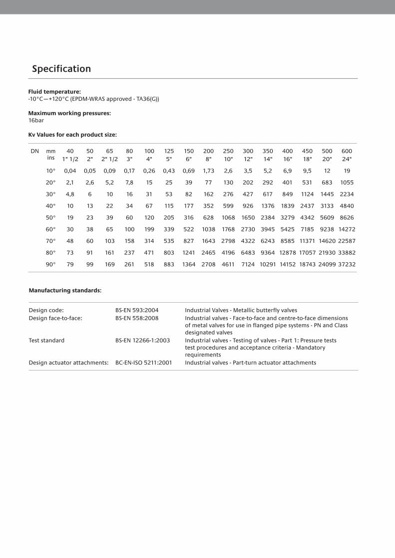
Fluid temperature:-10°C—+120°C (EPDM-WRAS approved - TA36(G))
Maximum working pressures:16bar
Kv Values for each product size:
DN mm ins
401" 1/2
502"
652" 1/2
803"
1004"
1255"
1506"
2008"
25010"
30012"
35014"
40016"
45018"
50020"
60024"
10° 0,04 0,05 0,09 0,17 0,26 0,43 0,69 1,73 2,6 3,5 5,2 6,9 9,5 12 19
20° 2,1 2,6 5,2 7,8 15 25 39 77 130 202 292 401 531 683 1055
30° 4,8 6 10 16 31 53 82 162 276 427 617 849 1124 1445 2234
40° 10 13 22 34 67 115 177 352 599 926 1376 1839 2437 3133 4840
50° 19 23 39 60 120 205 316 628 1068 1650 2384 3279 4342 5609 8626
60° 30 38 65 100 199 339 522 1038 1768 2730 3945 5425 7185 9238 14272
70° 48 60 103 158 314 535 827 1643 2798 4322 6243 8585 11371 14620 22587
80° 73 91 161 237 471 803 1241 2465 4196 6483 9364 12878 17057 21930 33882
90° 79 99 169 261 518 883 1364 2708 4611 7124 10291 14152 18743 24099 37232
Manufacturing standards:
Design code: BS-EN 593:2004 Industrial Valves - Metallic butterfly valvesDesign face-to-face: BS-EN 558:2008 Industrial valves - Face-to-face and centre-to-face dimensions
of metal valves for use in flanged pipe systems - PN and Class designated valves
Test standard BS-EN 12266-1:2003 Industrial valves - Testing of valves - Part 1: Pressure teststest procedures and acceptance criteria - Mandatory requirements
Design actuator attachments: BC-EN-ISO 5211:2001 Industrial valves - Part-turn actuator attachments

J
BZ
B
J
R
min
. pip
e
W
Parallel key ISO R773 / DIN6885A
E
S
ISO5211
n° x q
DN350-600
G
L1
D
O
L
F2
L9D
N30
0-60
0L9
DN
25-2
50
DN25-300
9
F1
D
n° x M
ISO5211
n° x q
G
8
6
7
5
3
4
2
5
1
C
E
A
L2
T
E
S
L9 D
N25
-250
L9 D
N30
0-60
0
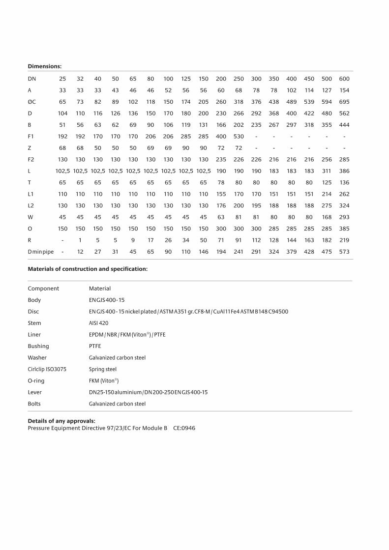
Dimensions:
DN 25 32 40 50 65 80 100 125 150 200 250 300 350 400 450 500 600
A 33 33 33 43 46 46 52 56 56 60 68 78 78 102 114 127 154
ØC 65 73 82 89 102 118 150 174 205 260 318 376 438 489 539 594 695
D 104 110 116 126 136 150 170 180 200 230 266 292 368 400 422 480 562
B 51 56 63 62 69 90 106 119 131 166 202 235 267 297 318 355 444
F1 192 192 170 170 170 206 206 285 285 400 530 - - - - - -
Z 68 68 50 50 50 69 69 90 90 72 72 - - - - - -
F2 130 130 130 130 130 130 130 130 130 235 226 226 216 216 216 256 285
L 102,5 102,5 102,5 102,5 102,5 102,5 102,5 102,5 102,5 190 190 190 183 183 183 311 386
T 65 65 65 65 65 65 65 65 65 78 80 80 80 80 80 125 136
L1 110 110 110 110 110 110 110 110 110 155 170 170 151 151 151 214 262
L2 130 130 130 130 130 130 130 130 130 176 200 195 188 188 188 275 324
W 45 45 45 45 45 45 45 45 45 63 81 81 80 80 80 168 293
O 150 150 150 150 150 150 150 150 150 300 300 300 285 285 285 285 385
R - 1 5 5 9 17 26 34 50 71 91 112 128 144 163 182 219
D min pipe - 12 27 31 45 65 90 110 146 194 241 291 324 379 428 475 573
Materials of construction and specification:
Component Material
Body EN GJS 400 - 15
Disc EN GJS 400 - 15 nickel plated / ASTM A351 gr. CF8-M / CuAl11Fe4 ASTM B148 C94500
Stem AISI 420
Liner EPDM / NBR / FKM (Viton®) / PTFE
Bushing PTFE
Washer Galvanized carbon steel
Cirlclip ISO3075 Spring steel
O-ring FKM (Viton®)
Lever DN25-150 aluminium / DN 200-250 EN GJS 400-15
Bolts Galvanized carbon steel
Details of any approvals: Pressure Equipment Directive 97/23/EC For Module B CE:0946
Graeme
Text Box
316 Stainless Steel
Graeme
Text Box
Graeme
Text Box
Graeme
Text Box
Graeme
Text Box
Graeme
Text Box
Graeme
Text Box
Graeme
Text Box
Epoxy Coated Ductule Iron
Graeme
Text Box
Graeme
Text Box
Graeme
Text Box
Graeme
Text Box
Graeme
Text Box
Graeme
Text Box

INSTALLATION AND TRANSPORT- Keep in dry and closed place. - While stored, the disc must be partially open (Fig. 1). - Avoid knocks, take special care to protect lever, hand wheel, gear boxes/actuators. - Do not use lever or hand wheel to lift
the valve.
MAINTENANCE The valve does not require maintenance.
RECOMMENDATIONS Before carrying out maintenance or dismantling the valve, be sure that the pipes, valves and liquids have cooled down, that the pressure has decreased and that the lines and pipes have been drained in case of toxic, corrosive, inflammable or caustic liquids. Temperatures above 50°C and below 0°C might cause damage to people.
INSTALLATION - Handle with care. - Do not weld the flanges to the piping after installing the valve. - Water hammers might cause damage and ruptures. Inclination, twisting and misalignments of the piping may subject the
valve to stress, once installed. It is recommended that elastic joints be used in order to reduce these effects as much as possible. The disc must be partially open (Fig. 1).
Specification
76 www.brandoni.it
Butterfly valves
Shu
t-of
f val
ves
The information provided here is delivered with each product, and contains “Instructions for use and maintenance”; it is also available on our website: www.brandoni.it (download section)
INSTALLATION AND TRANSPORT- Keep in dry and closed place.- While stored, the disc must be partially open (Fig. 1).- Avoid knocks, take special care to protect lever, hand wheel, gear boxes/actuators.- Do not use lever or hand wheel to lift the valve. MAINTENANCEThe valve does not require maintenance.
RECOMMENDATIONSBefore carrying out maintenance or dismantling the valve, be sure that the pipes, valves and liquids have cooled down, that the pressure has decreased and that the lines and pipes have been drained in case of toxic, corrosive, inflammable or caustic liquids.Temperatures above 50°C and below 0°C might cause damage to people.
INSTALLATION- Handle with care.- Do not weld the flanges to the piping after installing the valve.- Water hammers might cause damage and ruptures. Inclination, twisting and misalignments of the piping may subject the valve to stress, once installed. It is recommended that elastic joints be used in order to reduce these effects as much as possible. The disc must be partially open (Fig. 1).
FIG. 1 FIG. 2 FIG. 3
The stem has a machined notch N (Fig. 2), which indicates the position of the disc; consider this indication, in order to mount the levers and actuators correctly.The mounting can be made with the stem axis in a horizontal or vertical position. In case the fluid contains suspended solid particles (for example, sand, impurities, etc.) o solid particles that may leave deposits, it is recommend that the valve be installed with its axis horizontal, and in such a way that the bottom end of the disc opens in the direction of flow, F. (Fig. 3)The item L9 allows the dismantling of the pipes downstream, for pressures below 6 bar. For end of line installation:- SERIES J9 (all pressures), series L9 (pressure > 6 bar): counter flange MUST be installed- SERIES L9 (pressure< 6 bar): it is recommended that a counter flange be installed.Verify maximum working pressure and limits of use under section “maximum pressure”.Place the valve between two flanges. While placing the valve, ensure there is sufficient space in order in order not to dam-age the rubber. Do not mount seals between valve and flanges (Fig. 1). Carefully clean the contact surface. Do not install the butterfly valve in direct contact with a rubber surface (for example, expansion joints); the best installation is when the rubber is in contact with metal (Fig. 4).In order to achieve correct working, the internal diameter of the pipe must be greater than the value indicated in the chart. Do not weld the flanges to the tube if the valve has already been installed. It is recommended that the flanges listed in the chart be used. As far as possible, avoid flat flanges for welding (EN 1092 01 type); if these flanges are used, ensure perfect centring between the flange and valve, and be sure to weld exactly edgewise to the flange. Do not let protrusions or sharp edges on the piping cause damage to the rubber surface of the valve (Fig. 5).
Instruction and Recommendations for series J9 - L9
N
NO NO
F
FIG. 4
NO
FIG. 5
The stem has a machined notch N (Fig. 2), which indicates the position of the disc; consider this indication, in order to mount the levers and actuators correctly. The mounting can be made with the stem axis in a horizontal or vertical position. In case the fluid contains suspended solid particles (for example, sand, impurities, etc.) o solid particles that may leave deposits, it is recommend that the valve be installed with its axis horizontal, and in such a way that the bottom end of the disc opens in the direction of flow, F. (Fig. 3) The TA36 allows the dismantling of the pipes downstream, for pressures below 6 bar. For end of line installation counter flanges must be installed.

The products, texts, photographs, graphics and diagrams in this brochure may be subject to alteration without prior notice or reasons being given. For the most up to date information about our products and specifi cations, please visit www.tahydronics.com.
Place the valve between two flanges. While placing the valve, ensure there is sufficient space in order in order not to damage the rubber. Do not mount seals between valve and flanges (Fig. 1). Carefully clean the contact surface. Do not install the butterfly valve in direct contact with a rubber surface (for example, expansion joints); the best installation is when FIG. 4 FIG. 5 the rubber is in contact with metal (Fig. 4). In order to achieve correct working, the internal diameter of the pipe must be greater than the value indicated in NO the chart. Do not weld the flanges to the tube if the valve has already been installed. It is recommended that the flanges listed in the chart be used. As far as possible, avoid flat flanges for welding (EN 1092 01 type); if these flanges are used, ensure perfect centring between the flange and valve, and be sure to weld exactly edgewise to the flange. Do not let protrusions or sharp edges on the piping cause damage to the rubber surface of the valve (Fig. 5).
Centre the valve on holes while using wafer type valves. FIG. 6 Tighten the bolts crosswise and progressively, in order to distri-bute the pressure equally before the body and flanges come into contact with each other. (Fig. 6) With regard to the Lug version, check that the screws are the correct length, in order to allow complete compression of the lining rubber.
Turbulences of the fluid might increase erosion and reduce the life-cycle of the valve. Install the valve at a distance of at least 1 x DN upstream, and at a distance of 2-3 x DN down-stream, away from fittings or bends. In the open position, the valve is larger than the nominal Face to Face value. Check that no other components of the piping interfere or create damage or malfunction (Fig. 7A). If they do, a spacer should be inserted for the valve to operate correctly (Fig. 7B).
76 www.brandoni.it
Butterfly valves
Shu
t-of
f val
ves
The information provided here is delivered with each product, and contains “Instructions for use and maintenance”; it is also available on our website: www.brandoni.it (download section)
INSTALLATION AND TRANSPORT- Keep in dry and closed place.- While stored, the disc must be partially open (Fig. 1).- Avoid knocks, take special care to protect lever, hand wheel, gear boxes/actuators.- Do not use lever or hand wheel to lift the valve. MAINTENANCEThe valve does not require maintenance.
RECOMMENDATIONSBefore carrying out maintenance or dismantling the valve, be sure that the pipes, valves and liquids have cooled down, that the pressure has decreased and that the lines and pipes have been drained in case of toxic, corrosive, inflammable or caustic liquids.Temperatures above 50°C and below 0°C might cause damage to people.
INSTALLATION- Handle with care.- Do not weld the flanges to the piping after installing the valve.- Water hammers might cause damage and ruptures. Inclination, twisting and misalignments of the piping may subject the valve to stress, once installed. It is recommended that elastic joints be used in order to reduce these effects as much as possible. The disc must be partially open (Fig. 1).
FIG. 1 FIG. 2 FIG. 3
The stem has a machined notch N (Fig. 2), which indicates the position of the disc; consider this indication, in order to mount the levers and actuators correctly.The mounting can be made with the stem axis in a horizontal or vertical position. In case the fluid contains suspended solid particles (for example, sand, impurities, etc.) o solid particles that may leave deposits, it is recommend that the valve be installed with its axis horizontal, and in such a way that the bottom end of the disc opens in the direction of flow, F. (Fig. 3)The item L9 allows the dismantling of the pipes downstream, for pressures below 6 bar. For end of line installation:- SERIES J9 (all pressures), series L9 (pressure > 6 bar): counter flange MUST be installed- SERIES L9 (pressure< 6 bar): it is recommended that a counter flange be installed.Verify maximum working pressure and limits of use under section “maximum pressure”.Place the valve between two flanges. While placing the valve, ensure there is sufficient space in order in order not to dam-age the rubber. Do not mount seals between valve and flanges (Fig. 1). Carefully clean the contact surface. Do not install the butterfly valve in direct contact with a rubber surface (for example, expansion joints); the best installation is when the rubber is in contact with metal (Fig. 4).In order to achieve correct working, the internal diameter of the pipe must be greater than the value indicated in the chart. Do not weld the flanges to the tube if the valve has already been installed. It is recommended that the flanges listed in the chart be used. As far as possible, avoid flat flanges for welding (EN 1092 01 type); if these flanges are used, ensure perfect centring between the flange and valve, and be sure to weld exactly edgewise to the flange. Do not let protrusions or sharp edges on the piping cause damage to the rubber surface of the valve (Fig. 5).
Instruction and Recommendations for series J9 - L9
N
NO NO
F
FIG. 4
NO
FIG. 5
www.brandoni.it
Shu
t-of
f val
ves
Serie J9 - L9
77
Centre the valve on holes while using wafer type valves.Tighten the bolts crosswise and progressively, in order to distri-bute the pressure equally before the body and flanges come into contact with each other. (Fig. 6)With regard to the Lug version, check that the screws are the correct length, in order to allow complete compression of the lining rubber.Turbulences of the fluid might increase erosion and reduce the life-cycle of the valve. Install the valve at a distance of at least 1 x DN upstream, and at a distance of 2-3 x DN down-stream, away from fittings or bends.In the open position, the valve is larger than the nominal Face to Face value.Check that no other components of the piping interfere or create damage or malfunction (Fig. 7A). If they do, a spacer should be inserted for the valve to operate correctly (Fig. 7B).
FIG. 6
NOT OK OK FIG. 7A FIG. 7B
FLANGES CHART
Norms
EN 1092-1PN6/10/16
ANSI B16.1 #150* ANSI B16.5 #150*
Type
Type 11 weld neckType 21 integralType 02 + 35 loose plate with weld ring neckType 02 + 36 loose plate with pressed collarType 04 + 34 loose plate with weld neck collar
flat face
raised face
lap joint
CHART MINIMUM DIAMETER OF PIPES
DN 25 32 40 50 65 80 100 125 150 200 250 300 350 400 450 500 600Ø min. pipe - 12 27 31 45 65 90 110 146 194 241 291 324 379 428 475 573
Graeme
Text Box
Graeme
Text Box
0315.02
Graeme
Text Box
Graeme
Text Box
Graeme
Text Box